WO2021186490A1 - 空気調和機 - Google Patents
空気調和機 Download PDFInfo
- Publication number
- WO2021186490A1 WO2021186490A1 PCT/JP2020/011357 JP2020011357W WO2021186490A1 WO 2021186490 A1 WO2021186490 A1 WO 2021186490A1 JP 2020011357 W JP2020011357 W JP 2020011357W WO 2021186490 A1 WO2021186490 A1 WO 2021186490A1
- Authority
- WO
- WIPO (PCT)
- Prior art keywords
- heat exchanger
- outdoor heat
- compressor
- control unit
- control
- Prior art date
- Legal status (The legal status is an assumption and is not a legal conclusion. Google has not performed a legal analysis and makes no representation as to the accuracy of the status listed.)
- Ceased
Links
Images





Classifications
-
- F—MECHANICAL ENGINEERING; LIGHTING; HEATING; WEAPONS; BLASTING
- F24—HEATING; RANGES; VENTILATING
- F24F—AIR-CONDITIONING; AIR-HUMIDIFICATION; VENTILATION; USE OF AIR CURRENTS FOR SCREENING
- F24F11/00—Control or safety arrangements
- F24F11/30—Control or safety arrangements for purposes related to the operation of the system, e.g. for safety or monitoring
- F24F11/41—Defrosting; Preventing freezing
-
- F—MECHANICAL ENGINEERING; LIGHTING; HEATING; WEAPONS; BLASTING
- F24—HEATING; RANGES; VENTILATING
- F24F—AIR-CONDITIONING; AIR-HUMIDIFICATION; VENTILATION; USE OF AIR CURRENTS FOR SCREENING
- F24F11/00—Control or safety arrangements
- F24F11/70—Control systems characterised by their outputs; Constructional details thereof
- F24F11/80—Control systems characterised by their outputs; Constructional details thereof for controlling the temperature of the supplied air
- F24F11/86—Control systems characterised by their outputs; Constructional details thereof for controlling the temperature of the supplied air by controlling compressors within refrigeration or heat pump circuits
-
- F—MECHANICAL ENGINEERING; LIGHTING; HEATING; WEAPONS; BLASTING
- F24—HEATING; RANGES; VENTILATING
- F24F—AIR-CONDITIONING; AIR-HUMIDIFICATION; VENTILATION; USE OF AIR CURRENTS FOR SCREENING
- F24F11/00—Control or safety arrangements
- F24F11/70—Control systems characterised by their outputs; Constructional details thereof
- F24F11/80—Control systems characterised by their outputs; Constructional details thereof for controlling the temperature of the supplied air
- F24F11/87—Control systems characterised by their outputs; Constructional details thereof for controlling the temperature of the supplied air by controlling absorption or discharge of heat in outdoor units
- F24F11/871—Control systems characterised by their outputs; Constructional details thereof for controlling the temperature of the supplied air by controlling absorption or discharge of heat in outdoor units by controlling outdoor fans
Definitions
- the present invention relates to an air conditioner.
- Patent Document 1 states that the evaporation temperature of the heat exchanger to be cleaned is adjusted according to the target evaporation temperature of the heat exchanger to be cleaned and the actual evaporation temperature. It is described that the heat exchanger to be cleaned is frosted.
- Patent Document 1 when the outdoor heat exchanger is frosted based on the technique described in Patent Document 1, the refrigerant flowing through the outdoor heat exchanger becomes low in temperature and the proportion of the liquid refrigerant increases. After that, for example, when the heating operation is started, the liquid refrigerant accumulated in the outdoor heat exchanger may flow into the accumulator, and the liquid refrigerant may overflow from the accumulator to cause liquid compression in the compressor. .. Patent Document 1 does not describe a technique for preventing such liquid compression and increasing the reliability of the air conditioner.
- an object of the present invention is to provide a highly reliable air conditioner that keeps the outdoor heat exchanger in a clean state.
- the air conditioner according to the present invention includes a compressor, an indoor heat exchanger, an expansion valve, a refrigerant circuit having an outdoor heat exchanger, an indoor fan, an outdoor fan, and a control unit.
- the control unit operates the outdoor heat exchanger as an evaporator, and drives the compressor as the first control after performing a process of freezing or dew condensation on the outdoor heat exchanger.
- the compressor is stopped and the rotation speed of the outdoor fan is increased to be higher than that during the processing, and the rotation speed of the compressor is reduced to be lower than that during the processing while driving the compressor.
- it was decided to control the opening degree of the expansion valve to be larger than that at the time of the processing while driving the compressor.
- FIG. 1 is a configuration diagram of an air conditioner 100 according to the first embodiment.
- the solid arrow in FIG. 1 indicates the flow of the refrigerant during the heating cycle.
- the broken line arrow in FIG. 1 indicates the flow of the refrigerant during the cooling cycle.
- the air conditioner 100 is a device that performs air conditioning such as cooling operation and heating operation. As shown in FIG. 1, the air conditioner 100 includes a compressor 11, an accumulator 12, an outdoor heat exchanger 13, an outdoor fan 14, an expansion valve 15, and four-way valves as devices installed in the outdoor unit Uo. It is equipped with a valve 18. Further, the air conditioner 100 includes an indoor heat exchanger 16 and an indoor fan 17 as devices installed in the indoor unit Ui.
- the compressor 11 is a device that compresses a low-temperature low-pressure gas refrigerant and discharges it as a high-temperature high-pressure gas refrigerant, and includes a compressor motor 11a (see FIG. 3) as a drive source.
- the accumulator 12 is a shell-shaped member for gas-liquid separation of the refrigerant directed to the compressor 11, and is connected to the suction side of the compressor 11.
- the outdoor heat exchanger 13 is a heat exchanger in which heat exchange is performed between the refrigerant passing through the heat transfer tube g (see FIG. 2) and the outside air sent from the outdoor fan 14.
- the outdoor fan 14 is a fan that sends outside air to the outdoor heat exchanger 13.
- the outdoor fan 14 includes an outdoor fan motor 14a as a drive source, and is installed in the vicinity of the outdoor heat exchanger 13.
- the expansion valve 15 is a valve that reduces the pressure of the refrigerant condensed by the "condenser” (one of the outdoor heat exchanger 13 and the indoor heat exchanger 16).
- the refrigerant decompressed by the expansion valve 15 is guided to an "evaporator” (the other of the outdoor heat exchanger 13 and the indoor heat exchanger 16).
- the indoor heat exchanger 16 is a heat exchanger in which heat is exchanged between the refrigerant passing through the heat transfer tube (not shown) and the indoor air (air in the air conditioning room) sent from the indoor fan 17. be.
- the indoor fan 17 is a fan that sends indoor air to the indoor heat exchanger 16.
- the indoor fan 17 includes an indoor fan motor 17a (see FIG. 3) as a drive source, and is installed in the vicinity of the indoor heat exchanger 16.
- the four-way valve 18 is a valve that switches the flow path of the refrigerant according to the operation mode of the air conditioner 100.
- the compressor 11 the indoor heat exchanger 16 (condenser), the expansion valve 15, and the outdoor heat exchanger 13 (evaporator).
- the refrigerant circulates in sequence.
- the cooling cycle see the broken arrow in FIG. 1
- the refrigerant circulates in sequence.
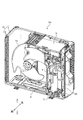
- FIG. 2 is a perspective view showing a state in which the side plate and the top plate of the housing of the outdoor unit Uo are removed.
- the expansion valve 15 see FIG. 1
- the four-way valve 18 see FIG. 1 are not shown.
- the outdoor heat exchanger 13 having an L shape in a plan view is installed on the bottom plate d of the housing of the outdoor unit Uo.
- the outdoor heat exchanger 13 includes a large number of fins f arranged at predetermined intervals, and a plurality of heat transfer tubes g penetrating the fins f. Then, the refrigerant flows through the heat transfer tube g described above while meandering in a predetermined manner.
- the electrical component box h shown in FIG. 2 is a box for accommodating a substrate (not shown) on which the outdoor control circuit 32 (see FIG. 3) described later is mounted.
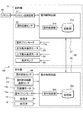
- FIG. 3 is a functional block diagram of the air conditioner 100.
- the indoor unit Ui shown in FIG. 3 includes a remote controller transmission / reception unit 21, an indoor temperature sensor 22, a left and right wind direction plate motor 23, a vertical wind direction plate motor 24, and an indicator lamp 25. (Display unit) and an indoor control circuit 31 are provided.
- the remote controller transmission / reception unit 21 exchanges predetermined information with the remote controller 40 by infrared communication or the like.
- the indoor temperature sensor 22 is a sensor that detects the indoor temperature (temperature of the air conditioning room), and is installed at a predetermined position of the indoor unit Ui. The signal received from the remote controller 40 via the remote controller transmitter / receiver 21 and the detection value of the indoor temperature sensor 22 are output to the indoor control circuit 31.
- the indoor fan motor 17a is a drive source for the indoor fan 17 (see FIG. 1).
- the left / right wind direction plate motor 23 is a motor that adjusts the angle of the left / right wind direction plate (not shown) in the left-right direction.
- the vertical wind direction plate motor 24 is a motor that adjusts the vertical angle of the vertical wind direction plate (not shown).
- the indicator lamp 25 is a lamp that performs a predetermined display, and is installed at a predetermined position of the indoor unit Ui. For example, during the cleaning process of the outdoor heat exchanger 13, the control unit 30 lights (or blinks) the indicator lamp 25 in a predetermined manner.
- the indoor control circuit 31 includes electronic circuits such as a CPU (Central Processing Unit), a ROM (Read Only Memory), a RAM (Random Access Memory), and various interfaces. Then, the program stored in the ROM is read out and expanded in the RAM, and the CPU executes various processes.
- a CPU Central Processing Unit
- ROM Read Only Memory
- RAM Random Access Memory
- the indoor control circuit 31 includes a storage unit 31a and an indoor control unit 31b.
- the storage unit 31a stores data received via the remote controller transmission / reception unit 21, detection values of each sensor, and the like.
- the indoor control unit 31b controls the indoor fan motor 17a, the left and right wind direction plate motor 23, the vertical wind direction plate motor 24, the indicator lamp 25, and the like based on the data stored in the storage unit 31a.
- the outdoor unit Uo includes an outdoor temperature sensor 26, an outdoor heat exchanger temperature sensor 27, and an outdoor control circuit 32, in addition to the above-described configuration (see FIG. 1).
- the outdoor temperature sensor 26 is a sensor that detects the outdoor temperature (the temperature of the outside air), and is installed at a predetermined position of the outdoor unit Uo.
- the outdoor heat exchanger temperature sensor 27 is a sensor that detects the temperature of the outdoor heat exchanger 13, and is provided, for example, in a pipe near the upstream end or the downstream end of the outdoor heat exchanger 13.
- each sensor for detecting one or more of the discharge pressure, the discharge temperature, the suction pressure, and the suction temperature of the compressor 11 may be appropriately provided.
- the detected value of each sensor including the outdoor temperature sensor 26 and the outdoor heat exchanger temperature sensor 27 is output to the outdoor control circuit 32.
- the outdoor control circuit 32 includes electronic circuits such as a CPU, ROM, RAM, and various interfaces, and is connected to the indoor control circuit 31 via a communication line. As shown in FIG. 3, the outdoor control circuit 32 includes a storage unit 32a and an outdoor control unit 32b.
- the storage unit 32a stores a predetermined program, data received from the indoor control circuit 31 via the communication line, and the detection value of each sensor.
- the outdoor control unit 32b controls the compressor motor 11a, the outdoor fan motor 14a, the expansion valve 15, the four-way valve 18, and the like based on the data stored in the storage unit 32a.
- control unit 30 the indoor control circuit 31 and the outdoor control circuit 32 are collectively referred to as “control unit 30”.
- FIG. 4 is a flowchart relating to the cleaning process of the outdoor heat exchanger 13 (see FIGS. 1 and 3 as appropriate).
- the control unit 30 determines whether or not the condition for starting the cleaning process of the outdoor heat exchanger 13 is satisfied. For example, when a predetermined period has elapsed since the end of the previous cleaning process, the control unit 30 determines that the start condition of the cleaning process of the outdoor heat exchanger 13 is satisfied (S101: Yes), and steps. Proceed to the process of S102.
- step S101 when there is a command to start the cleaning process of the outdoor heat exchanger 13 by operating the remote controller 40, the control unit 30 may start the cleaning process.
- step S101 when the start condition of the cleaning process of the outdoor heat exchanger 13 is not satisfied (S101: No), the control unit 30 ends a series of processes related to the cleaning process (END). The series of processes shown in FIG. 4 is performed every time the cleaning process start condition (S101) is satisfied.
- step S102 the control unit 30 freezes the outdoor heat exchanger 13. That is, the control unit 30 circulates the refrigerant in the refrigerant circuit Q in the heating cycle, causes the outdoor heat exchanger 13 to function as an evaporator, and freezes the outdoor heat exchanger 13.
- the "freezing" of the outdoor heat exchanger 13 means that the temperature of the outdoor heat exchanger 13 is kept below a predetermined value (below freezing point) for a predetermined time.
- step S103 the control unit 30 executes the liquid return prevention control (first control).
- the "liquid return prevention control” is a control for preventing liquid compression in which the liquid refrigerant flows into the compressor 11.
- a state in which the detected value of the outdoor heat exchanger temperature sensor 27 (see FIG. 3) is equal to or less than a predetermined value is predetermined.
- the control unit 30 may perform the liquid return prevention control (first control). Further, for example, when the elapsed time from the start of the process of freezing the outdoor heat exchanger 13 reaches a predetermined time, the control unit 30 may perform the liquid return prevention control (first control). The details of the liquid return prevention control will be described later.
- step S104 the control unit 30 defrosts the outdoor heat exchanger 13.
- the control unit 30 makes the opening degree of the expansion valve 15 larger than that at the time of freezing.
- the high-temperature refrigerant of the indoor unit Ui flows into the outdoor heat exchanger 13 on the low-voltage side via the expansion valve 15.
- the frost and ice of the outdoor heat exchanger 13 are melted, and the dust and salt of the outdoor heat exchanger 13 are washed away.
- step S105 the control unit 30 dries the outdoor heat exchanger 13.
- the control unit 30 drives the outdoor fan 14 to send outside air to the outdoor heat exchanger 13.
- the control unit 30 ends a series of processes related to the cleaning process (END).
- the control unit 30 may drive the compressor 11 in a cooling cycle to cause the outdoor heat exchanger 13 to function as a condenser, and the outdoor heat exchanger 13 may be dried.
- the control unit 30 appropriately performs the air conditioning operation according to the operation of the remote controller 40 until the start condition of the next cleaning process is satisfied again. Next, details such as liquid return prevention control will be described.
- FIG. 5 is a time chart showing the states of the compressor 11, the four-way valve 18, the expansion valve 15, the outdoor fan 14, and the indoor fan 17 (see FIGS. 1 and 3 as appropriate).
- the horizontal axis of FIG. 5 is time.
- the vertical axis of FIG. 5 shows the state of the compressor 11, the four-way valve 18, and the like.
- the air conditioner 100 is in the stopped state until the time t1. Then, as shown in the state of the four-way valve 18, it is assumed that, for example, the cooling operation was performed before the air conditioner 100 was stopped.
- the control unit 30 switches the four-way valve 18 to the heating cycle at time t1, narrows the expansion valve 15 to a predetermined opening k1, and drives the compressor 11. Let me.
- the control unit 30 may gradually reduce the opening degree of the expansion valve 15 as in the heating operation.
- the low-pressure refrigerant having a saturation temperature (evaporation temperature) lower than 0 ° C. passes through the outdoor heat exchanger 13.
- the control unit 30 drives the outdoor fan 14 and the indoor fan 17 at a lower speed than during normal air conditioning operation. As a result, frost and ice are likely to grow in the outdoor heat exchanger 13 even when the temperature of the outside air is relatively high. Further, during the freezing of the outdoor heat exchanger 13, the control unit 30 drives the indoor fan 17 at a low speed, so that the high temperature air exchanged by the indoor heat exchanger 16 (condenser) is blown into the room. Can be suppressed. While the outdoor heat exchanger 13 is frozen, the control unit 30 may drive the indoor fan 17 at a relatively high speed. As a result, the proportion of the refrigerant condensed in the indoor heat exchanger 16 increases, and the freezing of the outdoor heat exchanger 13 tends to proceed accordingly.
- the control unit 30 executes the liquid return prevention control (S103 in FIG. 4).
- the control unit 30 controls the compressor 11, the outdoor fan 14, and the expansion valve 15 as follows.
- the control unit 30 exchanges the rotation speed of the compressor 11 with the outdoor heat as the liquid return prevention control (first control) after the process of freezing the outdoor heat exchanger 13 while driving the compressor 11. Make it smaller than during the freezing process of the vessel 13.
- the compressor 11 is driven at a rotation speed Nc2 (time t2 to t3) smaller than the rotation speed Nc1 (time t1 to t2) at the time of freezing of the outdoor heat exchanger 13. ing.
- Nc2 time t2 to t3
- Nc1 time t1 to t2
- control unit 30 sets the rotation speed of the outdoor fan 14 to be higher than that during the freezing process of the outdoor heat exchanger 13 while driving the compressor 11 as the liquid return prevention control (S103 in FIG. 4).
- the outdoor fan 14 is driven at a rotation speed Nfo2 (time t2 to t3) higher than the rotation speed Nfo1 (time t1 to t2) at the time of freezing of the outdoor heat exchanger 13. ing.
- Nfo2 time t2 to t3
- Nfo1 time t1 to t2
- the control unit 30 sets the opening degree of the expansion valve 15 to be larger than that during the freezing process of the outdoor heat exchanger 13 while driving the compressor 11 as the liquid return prevention control (S103 in FIG. 4).
- the expansion valve 15 has an opening degree k2 larger than the opening degree k1 (time t1 to t2) at the time of freezing of the outdoor heat exchanger 13.
- the depressurization of the refrigerant in the expansion valve 15 is suppressed.
- the temperature and pressure of the refrigerant in the outdoor heat exchanger 13 rise, and gasification of the refrigerant is promoted.
- the execution time of the liquid return prevention control (time from time t2 to t3) may be set in advance. That is, after the freezing of the outdoor heat exchanger 13 is completed, the control unit 30 may execute the liquid return prevention control for a predetermined time. In addition, for example, the control unit 30 may execute the liquid return prevention control until the outdoor heat exchanger 13 reaches a predetermined temperature.
- control unit 30 continues to drive the compressor 11 when shifting from the freezing of the outdoor heat exchanger 13 to the liquid return prevention control (time t2 in FIG. 5).
- time t2 in FIG. 5 it is possible to prevent the liquid from returning when the control unit 30 temporarily stops the compressor 11 and starts driving again.
- the time required for a series of processes including freezing, liquid return prevention control, thawing, and drying of the outdoor heat exchanger 13 can be shortened.
- the valve body (not shown) of the four-way valve 18 is in the heating cycle position, and the indoor fan 17 is in the stopped state. It has become.
- the control unit 30 may appropriately drive the indoor fan 17 during the liquid return prevention control. As a result, the discharge pressure of the compressor 11 can be prevented from becoming too high, and the reliability of the air conditioner 100 can be ensured.
- control unit 30 appropriately changes one or more of the rotation speed of the compressor 11, the rotation speed of the outdoor fan 14, and the opening degree of the expansion valve 15. May be good. Then, as a liquid return prevention control, the control unit 30 sets the rotation speed of the compressor 11 to be smaller than the temporal average value (or maximum value) of the rotation speed of the compressor 11 when the outdoor heat exchanger 13 is frozen. You may try to do it.
- the control unit 30 sets the rotation speed of the outdoor fan 14 to be larger than the temporal average value (or minimum value) of the rotation speed of the outdoor fan 14 when the outdoor heat exchanger 13 is frozen. You may try to make it larger. Further, as a liquid return prevention control, the control unit 30 sets the opening degree of the expansion valve 15 larger than the temporal average value (or the minimum value) of the opening degree of the expansion valve 15 when the outdoor heat exchanger 13 is frozen. You may try to do it. Even with such control, gasification of the refrigerant in the outdoor heat exchanger 13 is promoted.
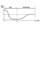
- FIG. 6 is an explanatory diagram showing a temperature change of the refrigerant of the outdoor heat exchanger during freezing of the outdoor heat exchanger and control of preventing liquid return (see FIGS. 1 and 3 as appropriate).
- the horizontal axis of FIG. 6 is the time, and the vertical axis is the temperature of the refrigerant in the outdoor heat exchanger 13.
- the times t1 to t3 shown in FIG. 6 correspond to the times t1 to t3 shown in FIG.
- the temperature of the refrigerant of the outdoor heat exchanger 13 gradually decreases from the predetermined temperature Ta during the time t1 to t2 during the freezing of the outdoor heat exchanger 13 (S102 in FIG. 4), and near the time t2.
- the predetermined temperature is Tb.
- the predetermined temperature Ta is often substantially equal to the temperature of the outside air, and the predetermined temperature Tb is often below the freezing point.
- a predetermined liquid return prevention control (S103 in FIG. 4) is performed, the temperature of the outdoor heat exchanger 13 gradually rises from the predetermined temperature Tb, and becomes a predetermined temperature Tc near the time t3. ing. As described above, the temperature of the refrigerant in the outdoor heat exchanger 13 rises and the gasification of the refrigerant is promoted, so that it is possible to prevent the compressor 11 from returning to the liquid thereafter.
- the predetermined temperature Tc shown in FIG. 6 may be 0 ° C. or higher, or may be lower than 0 ° C. In either case, the gasification of the refrigerant is promoted as the temperature of the refrigerant in the outdoor heat exchanger 13 rises (time t2 to t3). Further, since the freezing of the outdoor heat exchanger 13 is completed at the time t2, there is no particular problem even if the temperature of the outdoor heat exchanger 13 becomes 0 ° C. or higher due to the subsequent liquid return prevention control.
- the control unit 30 defrosts the outdoor heat exchanger 13. That is, the control unit 30 puts the compressor 11 in a stopped state and also puts the indoor fan 17 in a stopped state. Further, the control unit 30 drives the outdoor fan 14 during the thawing of the outdoor heat exchanger 13. Further, the control unit 30 defrosts the outdoor heat exchanger 13 by increasing the opening degree of the expansion valve 15 as compared with the case of freezing of the outdoor heat exchanger 13 or the control of preventing liquid return. In the example of FIG. 5, the expansion valve 15 is fully opened while the outdoor heat exchanger 13 is being thawed (time t3 to t4).
- the indoor heat exchanger 16 (high pressure side), which was functioning as a condenser during the freezing of the outdoor heat exchanger 13, is transferred to the outdoor heat exchanger 13 (low pressure side) via the expansion valve 15 as a high-temperature refrigerant. Flows in. As a result, the frost and ice of the outdoor heat exchanger 13 are melted, and the outdoor heat exchanger 13 is washed away.
- the control unit 30 continues to drive the outdoor fan 14 to dry the outdoor heat exchanger 13.
- the moisture on the surface of the outdoor heat exchanger 13 evaporates, and the outdoor heat exchanger 13 dries.
- the control unit 30 may drive the compressor 11 in a cooling cycle to cause the outdoor heat exchanger 13 to function as a condenser, and the outdoor heat exchanger 13 may be dried.
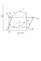
- FIG. 7 is a Moriel diagram when the outdoor heat exchanger is frozen and when the liquid return prevention control is performed (see also FIG. 1 as appropriate).
- the horizontal axis of FIG. 7 is the specific enthalpy of the refrigerant, and the vertical axis of FIG. 7 is the pressure of the refrigerant.
- the saturated vapor line ⁇ shown in FIG. 7 is a boundary line between the gas phase and the gas-liquid two-phase in the state of the refrigerant.
- the saturated liquid line ⁇ is a boundary line between the liquid phase and the gas-liquid two-phase in the state of the refrigerant. Further, in the region surrounded by the saturated vapor line ⁇ and the saturated liquid line ⁇ , the state of the refrigerant is gas-liquid two-phase.
- the boundary point between the saturated vapor line ⁇ and the saturated liquid line ⁇ is referred to as a critical point ⁇ .
- the inverted trapezoidal solid line N shown in FIG. 7 is a Moriel diagram when the outdoor heat exchanger 13 is frozen.
- the inverted alternate long and short dash line M shown in FIG. 7 is a Moriel diagram at the time of liquid return prevention control.
- the outdoor heat exchanger 13 is frozen (see solid line N)
- it is compressed (state Na ⁇ Nb), condensed (state Nb ⁇ Nc), expanded (state Nc ⁇ Nd), and evaporated (state Nc ⁇ Nd).
- the refrigerant circulates in a refrigeration cycle of state Nd ⁇ Na).
- the expansion valve 15 is throttled to a predetermined opening degree k1 (see time t1 to t2 in FIG. 5).
- the control unit 30 may gradually reduce the opening degree of the expansion valve 15 as in the heating operation.
- the pressure of the refrigerant (state Nd) expanded by the expansion valve 15 becomes lower than that during normal air conditioning operation, and the temperature of the refrigerant becomes lower accordingly.
- the outdoor heat exchanger 13 is frozen.
- the control unit 30 executes a predetermined liquid return prevention control after the outdoor heat exchanger 13 is frozen (S103 in FIG. 4).
- the temperature and pressure of the refrigerant in the outdoor heat exchanger 13 rise, and gasification of the refrigerant is promoted. Therefore, for example, even if the heating cycle is operated immediately after the cleaning process of the outdoor heat exchanger 13, it is possible to prevent the liquid refrigerant from flowing from the outdoor heat exchanger 13 into the compressor 11 via the accumulator 12. .. That is, since there is almost no possibility that liquid compression will occur in the compressor 11, the reliability of the air conditioner 100 can be improved. As described above, according to the first embodiment, it is possible to provide a highly reliable air conditioner 100 that keeps the outdoor heat exchanger 13 in a clean state.
- the second embodiment is different from the first embodiment in that the cleaning process of the outdoor heat exchanger 13 is repeated twice.
- the other points (configuration of the air conditioner 100: see FIGS. 1 to 3) are the same as those in the first embodiment. Therefore, a part different from the first embodiment will be described, and a description of the overlapping part will be omitted.
- FIG. 8 is a flowchart relating to the cleaning process of the outdoor heat exchanger of the air conditioner according to the second embodiment (see FIGS. 1 and 3 as appropriate). Steps S201 to S204 shown in FIG. 8 are the same as steps S101 to S104 (see FIG. 4) described in the first embodiment, but will be briefly described.
- step S201 start condition of the cleaning process of the outdoor heat exchanger 13 is satisfied in step S201 (S201: Yes)
- the process of the control unit 30 proceeds to step S202.
- step S202 the control unit 30 freezes the outdoor heat exchanger 13.
- the control unit 30 freezes both the upper part and the lower part of the outdoor heat exchanger 13 as the first freezing.
- substantially the entire outdoor heat exchanger 13 is frozen, and the subsequent thawing (S204) ishes away substantially the entire outdoor heat exchanger 13.
- step S203 the control unit 30 executes a predetermined liquid return prevention control. This promotes gasification of the refrigerant in the outdoor heat exchanger 13. Therefore, when the lower part of the outdoor heat exchanger 13 is subsequently frozen (S205), it is possible to prevent the liquid refrigerant from flowing from the outdoor heat exchanger 13 into the compressor 11. Since the liquid return prevention control (S203) is the same as that of the first embodiment (see time t2 to t3 in FIG. 5), the description thereof will be omitted.
- step S204 the control unit 30 defrosts the outdoor heat exchanger 13. That is, after performing the predetermined liquid return prevention control (first control: S203), the control unit 30 stops the compressor 11 and sets the opening degree of the expansion valve 15 when the outdoor heat exchanger 13 is frozen (processed). The outdoor heat exchanger 13 is thawed by making it larger than the hour (S204).
- steps S202 to S204 are the first cleaning process. After performing the first cleaning process in this way, the control unit 30 performs the second cleaning process (S205 to S207).
- step S205 the control unit 30 freezes the lower part of the outdoor heat exchanger 13.
- the control content for freezing the lower part of the outdoor heat exchanger 13 is the same as that for freezing both the upper part and the lower part of the outdoor heat exchanger 13 except that the duration of freezing is short (S202). Further, the control unit 30 may gradually reduce the opening degree of the expansion valve 15 as in the heating operation. In the second cleaning process, by freezing the lower part of the outdoor heat exchanger 13 (S205), freezing can be completed in a shorter time than freezing both the upper part and the lower part of the outdoor heat exchanger 13.
- the control unit 30 makes the rotation speed of the compressor 11 from the start of the compressor 11 until a predetermined time elapses smaller than that at the time of the first freezing (S202). It is preferable to do so. That is, the control unit 30 performs the second freezing process after thawing the outdoor heat exchanger 13, and in the second freezing (processing), the rotation speed of the compressor 11 is changed from the first freezing (processing). It is also preferable to make it smaller. As a result, the circulation amount of the refrigerant in the refrigerant circuit Q (see FIG. 1) is reduced, so that the flow rate of the refrigerant flowing through the outdoor heat exchanger 13 is also reduced.
- control unit 30 makes the opening degree of the expansion valve 15 smaller at the time of the second freezing than at the time of the first freezing.
- the lower part (upstream side) of the outdoor heat exchanger 13 freezes, while the refrigerant superheats (superheats) in the upper part (downstream side) of the outdoor heat exchanger 13 and gasifies. Therefore, even if the heating cycle is operated after that, there is almost no possibility that liquid compression will occur in the compressor 11.
- the control unit 30 For a predetermined time from the start of the second freezing (S205), the control unit 30 makes the rotation speed of the compressor 11 smaller than that at the time of the first freezing, and in the remaining time, the rotation speed of the compressor 11 is reduced. It may be increased or decreased as appropriate. Further, the temporal average value of the rotational speed of the compressor 11 in the second freezing may be smaller than the temporal average value of the rotational speed of the compressor 11 in the first freezing. Even in such a process, it is possible to prevent the liquid refrigerant from flowing into the compressor 11 at once. In addition, for example, the control unit 30 may set the starting rotation speed of the compressor 11 at the time of the second freezing (S205) to be smaller than the starting rotation speed at the time of the first freezing (S202). .. The same effect can be achieved with such control.
- step S206 the control unit 30 defrosts the outdoor heat exchanger 13.
- the control unit 30 makes the opening degree of the expansion valve 15 larger than that at the time of freezing (S205) at the lower part of the outdoor heat exchanger 13.
- the high-temperature refrigerant flows into the outdoor heat exchanger 13 through the expansion valve 15, and the frost and ice in the lower part of the outdoor heat exchanger 13 are melted.
- step S207 the control unit 30 dries the outdoor heat exchanger 13. That is, the control unit 30 drives the outdoor fan 14 for a predetermined time and sends the outside air to the outdoor heat exchanger 13. As a result, the moisture on the surface of the outdoor heat exchanger 13 evaporates, and the outdoor heat exchanger 13 dries. Alternatively, for example, the control unit 30 may drive the compressor 11 in the cooling cycle to dry the outdoor heat exchanger 13. After performing the process of step S207, the control unit 30 ends a series of processes related to the cleaning process (END).
- END cleaning process
- the predetermined liquid return prevention control (S203 in FIG. 8) is executed in the first cleaning process, when the lower part of the outdoor heat exchanger 13 is frozen (S205) after that, the compressor 11 It is possible to prevent the liquid from returning to. Further, when the lower part of the outdoor heat exchanger 13 is frozen in the second cleaning process (S205), the control unit 30 drives the compressor 11 at a lower speed than in the first freezing process. Thereby, the flow rate of the refrigerant from the outdoor heat exchanger 13 to the compressor 11 can be reduced. Further, in the upper part of the outdoor heat exchanger 13, the liquid refrigerant is superheated and gasified. Therefore, even if the heating operation is performed after the second cleaning process, it is possible to prevent the liquid from returning to the compressor 11.
- FIG. 9 is a time chart showing the states of the compressor, the four-way valve, the expansion valve, the outdoor fan, and the indoor fan in the air conditioner according to the modified example.
- the time chart of FIG. 9 is different from the first embodiment (see FIG. 5) in that the compressor 11 is in the stopped state during the liquid return prevention control (time t2 to t3), but other than that.
- the points are the same as those in the first embodiment.
- the control unit 30 stops the compressor 11 and drives the outdoor fan 14. That is, the control unit 30 controls the compressor 11 to be stopped and the rotation speed of the outdoor fan 14 to be higher than that during the freezing process of the outdoor heat exchanger 13. As a result, the outside air is sent into the gap between the fins f (see FIG. 2) of the outdoor heat exchanger 13, so that the temperature and pressure of the refrigerant of the outdoor heat exchanger 13 rise and the gasification of the refrigerant is promoted. .. Therefore, even if a heating operation or the like is performed after the cleaning process, it is possible to prevent the liquid from returning to the compressor 11.
- the expansion valve 15 is maintained at a predetermined opening degree k2 during the liquid return prevention control (time t2 to t3), but the present invention is not limited to this.
- the control unit 30 may open the expansion valve 15 substantially fully during the liquid return prevention control. In this case, the depressurization of the refrigerant is suppressed. As a result, the temperature and pressure of the refrigerant in the outdoor heat exchanger 13 rise, and the refrigerant is gasified.
- the control unit 30 may set the opening degree of the expansion valve 15 in the liquid return prevention control to the same opening degree as when the outdoor heat exchanger 13 is frozen. For example, the control unit 30 may continue to control (opening degree) the expansion valve 15 during freezing of the outdoor heat exchanger 13 to perform liquid return prevention control.
- the control unit 30 stops the compressor 11 as a liquid return prevention control (first control), and makes the rotation speed of the outdoor fan 14 higher than that at the time of freezing (processing) of the outdoor heat exchanger 13.
- first control liquid return prevention control
- the following processing may be performed.
- the time zone in which the control unit 30 performs the liquid return prevention control and the time zone in which the opening degree of the expansion valve 15 is made larger than that at the time of freezing (processing) of the outdoor heat exchanger 13 are at least partially overlapped. It may be.
- the time zones for preventing liquid return and thawing of the outdoor heat exchanger 13 overlap at least partially, so that the time required for a series of cleaning processes can be shortened.
- the present invention is not limited to this. That is, instead of freezing the outdoor heat exchanger 13, the control unit 30 may condense dew on the outdoor heat exchanger 13. When dew condensation occurs on the outdoor heat exchanger 13 in this way, the control unit 30 determines that the temperature of the outdoor heat exchanger 13 is equal to or lower than the dew point of the outside air and is higher than the predetermined freezing temperature. Adjust the opening degree of.
- the above-mentioned "freezing temperature” is a temperature at which the moisture contained in the air begins to freeze in the outdoor heat exchanger 13 when the temperature of the outdoor heat exchanger 13 is gradually lowered.
- the control unit 30 may drive the outdoor fan 14 to dry the outdoor heat exchanger 13.
- the control content (see FIG. 5) is the same as in the case of "freezing” except that the opening degree of the expansion valve 15 is larger in “condensation” than in the case of "freezing” the outdoor heat exchanger 13. ..
- the control unit 30 adjusts the rotation speed of the compressor 11 to reduce the amount of heat exchanged by the outdoor heat exchanger 13, and the outdoor heat exchanger 13 cools the air. The ability may be reduced.
- the rotation speed of the compressor 11, the rotation speed of the outdoor fan 14, and the opening degree of the expansion valve 15 are predeterminedly controlled as liquid return prevention control (S103 in FIG. 4 and S203 in FIG. 8).
- the control unit 30 controls the rotation speed of the outdoor fan 14 to be higher than that at the time of freezing (processing) of the outdoor heat exchanger 13 while driving the compressor 11, and the rotation speed of the compressor 11 at the time of freezing (during freezing). Control may be performed to make the opening degree of the expansion valve 15 smaller than that at the time of freezing (during processing) or to make it larger than at the time of freezing (during processing).
- the controls of the compressor 11, the outdoor fan 14, and the expansion valve 15 described above may be appropriately combined. Even with such control, gasification of the refrigerant in the outdoor heat exchanger 13 is promoted.
- the control unit 30 controls the rotation speed of the outdoor fan 14 to be lower than that at the time of freezing (processing) of the outdoor heat exchanger 13 while driving the compressor 11. It is preferable to make it larger than that at the time of freezing (during treatment). This makes it easier for the refrigerant to be gasified. This is because the drive of the outdoor fan 14 promotes heat exchange between the outside air and the refrigerant when the flow rate of the refrigerant in the outdoor heat exchanger 13 is small.
- the control unit 30 causes the control unit 30.
- each "predetermined value” regarding the indoor temperature and the outdoor temperature is a threshold value that serves as a criterion for determining whether or not to freeze (or condense) the outdoor heat exchanger 13, and is set in advance.
- the control unit 30 displays a predetermined display regarding the freezing including the cleaning process on the display lamp 25 (display unit: see FIG. 3), and the liquid after freezing (after the treatment). It is preferable to continue the predetermined display on the indicator lamp 25 even during the return prevention control (during the first control). As a result, the user can grasp that a predetermined process (liquid return prevention control) accompanying the freezing of the outdoor heat exchanger 13 is being performed. Therefore, even if the compressor 11 or the outdoor fan 14 is driven during the liquid return prevention control (time t2 to t3 in FIG. 5), it is possible to suppress the user from feeling uncomfortable.
- the control unit 30 continues the liquid return prevention control. Is preferable. As a result, it is possible to prevent the compressor 11 from causing liquid compression immediately after the start of the heating operation without completing the liquid return prevention control.
- control unit 30 provides a predetermined time from the end of the liquid return prevention control (first control) to a period during which the operation of the compressor 11 in the heating cycle is prohibited. For example, when a predetermined time has not passed since the end of the liquid return prevention control, a command to start the heating operation and a command to start the cleaning process of the outdoor heat exchanger 13 are input by operating the remote controller 40 (see FIG. 3). Even if this is done, the control unit 30 does not drive the compressor 11. As a result, the heat exchange between the refrigerant of the outdoor heat exchanger 13 and the outside air further promotes the gasification of the refrigerant of the outdoor heat exchanger 13.
- the control unit 30 may or may not drive the outdoor fan 14 in the above-mentioned "predetermined time". This is because even if the control unit 30 does not drive the outdoor fan 14, the refrigerant of the outdoor heat exchanger 13 is gasified by the natural convection of the outside air. Further, after the end of the liquid return prevention control, the period for prohibiting the driving of the compressor 11 in the heating cycle may be set to be longer than the duration of the liquid return prevention control prior to this. This promotes gasification of the refrigerant in the outdoor heat exchanger 13.
- control unit 30 drives the outdoor fan 14 at a predetermined rotation speed Nfo1 while the outdoor heat exchanger 13 is frozen (time t1 to t2 in FIG. 5) has been described, but the present invention is limited to this. No.
- the control unit 30 may maintain the outdoor fan 14 in a stopped state while the outdoor heat exchanger 13 is frozen. Then, in the liquid return prevention control (time t2 to t3 in FIG. 5), the control unit 30 may drive the outdoor fan 14 at a predetermined rotation speed Nfo2.
- the control for driving the outdoor fan 14 from the stopped state is also included in the matter that the rotation speed of the outdoor fan 14 is made higher than that at the time of freezing (processing) of the outdoor heat exchanger 13.
- control unit 30 drives the outdoor fan 14 while the outdoor heat exchanger 13 is being thawed (time t3 to t4 in FIG. 5) has been described, but the present invention is not limited to this.
- the control unit 30 may maintain the outdoor fan 14 in a stopped state while the outdoor heat exchanger 13 is thawed. This is because even if the outdoor fan 14 is stopped, the outdoor heat exchanger 13 is thawed by the natural convection of air.
- the opening degree of the expansion valve 15 (fully opened in the example of FIG. 5) at the time of thawing of the outdoor heat exchanger 13 (time t3 to t4 in FIG. 5) prevents the liquid return of the outdoor heat exchanger 13.
- the case where the opening degree is larger than the opening degree k2 in the control (time t2 to t3 in FIG. 5) has been described, but the present invention is not limited to this.
- the opening degree of the expansion valve 15 at the time of thawing of the outdoor heat exchanger 13 and the opening degree of the expansion valve 15 at the time of liquid return prevention control may be made substantially equal.
- the opening degree of the expansion valve 15 at the time of thawing of the outdoor heat exchanger 13 may be smaller than the opening degree of the expansion valve 15 at the time of liquid return prevention control.
- the control unit 30 controls the liquid return prevention control (S103) and thaw and dry the outdoor heat exchanger 13 (S104, S105).
- S103 liquid return prevention control
- S104, S105 thaw and dry the outdoor heat exchanger 13
- thawing and drying of the outdoor heat exchanger 13 may be omitted. This is because even if each device is maintained in a stopped state after the outdoor heat exchanger 13 is frozen, the outdoor heat exchanger 13 is naturally thawed and dried by the natural convection of air.
- the control unit 30 freezes the lower part of the outdoor heat exchanger 13 in the second cleaning process has been described (S205 in FIG. 8), but the present invention is not limited to this.
- the control unit 30 may freeze both the upper part and the lower part of the outdoor heat exchanger 13.
- the case where the liquid return prevention control (S203 in FIG. 8) is performed in the first cleaning process, while the liquid return prevention control is not particularly performed in the second cleaning process has been described. , Not limited to this.
- the control unit 30 freezes the lower part of the outdoor heat exchanger 13 (S205 in FIG.
- a predetermined liquid return prevention control is performed in the same manner as in the first cleaning process. You may.
- the control unit 30 may freeze both the upper part and the lower part of the outdoor heat exchanger 13. In this case, the control unit 30 freezes both the upper part and the lower part of the outdoor heat exchanger 13 in the second cleaning process, and then executes a predetermined liquid return prevention control.
- the control unit 30 freezes the outdoor heat exchanger 13 and then performs a predetermined liquid return prevention control and further defrosts the outdoor heat exchanger 13 has been described.
- the process of defrosting the exchanger 13 may be omitted. Since the temperature of the outdoor heat exchanger 13 rises and the outdoor fan 14 is also driven by the liquid return prevention control described above, the outdoor heat exchanger 13 is thawed without stopping the compressor 11. That is, after the control unit 30 sequentially performs the first freezing of the outdoor heat exchanger 13 and the liquid return prevention control, the second freezing of the outdoor heat exchanger 13 as it is without stopping the compressor 11. May be done. By continuing to drive the compressor 11 in this way, it becomes difficult for the liquid to return to the compressor 11.
- the present invention is not limited to this.
- another expansion valve (not shown) may be provided in the vicinity of the indoor heat exchanger 16.
- each embodiment the configuration in which one indoor unit Ui (see FIG. 1) and one outdoor unit Uo (see FIG. 1) are provided has been described, but the present invention is not limited to this. That is, a plurality of indoor units connected in parallel may be provided. Further, in addition to room air conditioners, each embodiment can be applied to various types of air conditioners such as package air conditioners and multi air conditioners for buildings.
- each embodiment is described in detail in order to explain the present invention in an easy-to-understand manner, and is not necessarily limited to the one including all the configurations described. Further, it is possible to add / delete / replace other configurations with respect to a part of the configurations of each embodiment.
- the above-mentioned mechanism and configuration show what is considered necessary for explanation, and do not necessarily show all the mechanisms and configurations in the product.
- Air conditioner 11 Compressor 12 Accumulator 13 Outdoor heat exchanger 14 Outdoor fan 15 Expansion valve 18 Four-way valve 16 Indoor heat exchanger 17 Indoor fan 21 Remote control transmitter / receiver 22 Indoor temperature sensor 25 Indicator lamp (display) 26 Outdoor temperature sensor 27 Outdoor heat exchanger temperature sensor 30 Control unit 40 Remote control Q Refrigerant circuit Ui Indoor unit Uo Outdoor unit
Landscapes
- Engineering & Computer Science (AREA)
- Chemical & Material Sciences (AREA)
- Combustion & Propulsion (AREA)
- Mechanical Engineering (AREA)
- General Engineering & Computer Science (AREA)
- Physics & Mathematics (AREA)
- Thermal Sciences (AREA)
- Air Conditioning Control Device (AREA)
Abstract
室外熱交換器を清潔な状態にする信頼性の高い空気調和機を提供する。空気調和機(100)の制御部(30)は、室外熱交換器(13)を蒸発器として機能させ、室外熱交換器(13)を凍結又は結露させる処理を行った後の第1制御として、圧縮機(11)を駆動させながら、若しくは、圧縮機(11)を停止状態にして、室外ファン(14)の回転速度を前記処理時よりも大きくする制御、圧縮機(11)を駆動させながら、圧縮機(11)の回転速度を前記処理時よりも小さくする制御、又は、圧縮機(11)を駆動させながら、膨張弁(15)の開度を前記処理時よりも大きくする制御を行う。
Description
本発明は、空気調和機に関する。
空気調和機の熱交換器を洗浄する技術として、例えば、特許文献1には、被洗浄熱交換器の目標蒸発温度及び実際の蒸発温度に応じて被洗浄熱交換器の蒸発温度を調節し、被洗浄熱交換器に着霜させることが記載されている。
例えば、特許文献1に記載の技術に基づいて、室外熱交換器を着霜させると、室外熱交換器を流れる冷媒が低温になり、液冷媒の割合が多くなる。その後に、例えば、暖房運転が開始された場合、室外熱交換器に溜まっていた液冷媒がアキュムレータに流れ込み、さらに、アキュムレータから液冷媒が溢れ出て、圧縮機で液圧縮が生じる可能性がある。このような液圧縮を防止し、空気調和機の信頼性を高めるための技術について、特許文献1には記載されていない。
そこで、本発明は、室外熱交換器を清潔な状態にする信頼性の高い空気調和機を提供することを課題とする。
前記した課題を解決するために、本発明に係る空気調和機は、圧縮機、室内熱交換器、膨張弁、及び室外熱交換器を有する冷媒回路と、室内ファン及び室外ファンと、制御部と、を備え、前記制御部は、前記室外熱交換器を蒸発器として機能させ、前記室外熱交換器を凍結又は結露させる処理を行った後の第1制御として、前記圧縮機を駆動させながら、若しくは、前記圧縮機を停止状態にして、前記室外ファンの回転速度を前記処理時よりも大きくする制御、前記圧縮機を駆動させながら、前記圧縮機の回転速度を前記処理時よりも小さくする制御、又は、前記圧縮機を駆動させながら、前記膨張弁の開度を前記処理時よりも大きくする制御を行うこととした。
本発明によれば、室外熱交換器を清潔な状態にする信頼性の高い空気調和機を提供できる。
≪第1実施形態≫
<空気調和機の構成>
図1は、第1実施形態に係る空気調和機100の構成図である。
なお、図1の実線矢印は、暖房サイクル時の冷媒の流れを示している。
一方、図1の破線矢印は、冷房サイクル時の冷媒の流れを示している。
空気調和機100は、冷房運転や暖房運転等の空調を行う機器である。図1に示すように、空気調和機100は、室外機Uoに設置される機器として、圧縮機11と、アキュムレータ12と、室外熱交換器13と、室外ファン14と、膨張弁15と、四方弁18と、を備えている。また、空気調和機100は、室内機Uiに設置される機器として、室内熱交換器16と、室内ファン17と、を備えている。
<空気調和機の構成>
図1は、第1実施形態に係る空気調和機100の構成図である。
なお、図1の実線矢印は、暖房サイクル時の冷媒の流れを示している。
一方、図1の破線矢印は、冷房サイクル時の冷媒の流れを示している。
空気調和機100は、冷房運転や暖房運転等の空調を行う機器である。図1に示すように、空気調和機100は、室外機Uoに設置される機器として、圧縮機11と、アキュムレータ12と、室外熱交換器13と、室外ファン14と、膨張弁15と、四方弁18と、を備えている。また、空気調和機100は、室内機Uiに設置される機器として、室内熱交換器16と、室内ファン17と、を備えている。
圧縮機11は、低温低圧のガス冷媒を圧縮し、高温高圧のガス冷媒として吐出する機器であり、駆動源である圧縮機モータ11a(図3参照)を備えている。
アキュムレータ12は、圧縮機11に向かう冷媒を気液分離するための殻状部材であり、圧縮機11の吸入側に接続されている。
アキュムレータ12は、圧縮機11に向かう冷媒を気液分離するための殻状部材であり、圧縮機11の吸入側に接続されている。
室外熱交換器13は、その伝熱管g(図2参照)を通流する冷媒と、室外ファン14から送り込まれる外気と、の間で熱交換が行われる熱交換器である。
室外ファン14は、室外熱交換器13に外気を送り込むファンである。室外ファン14は、駆動源である室外ファンモータ14aを備え、室外熱交換器13の付近に設置されている。
室外ファン14は、室外熱交換器13に外気を送り込むファンである。室外ファン14は、駆動源である室外ファンモータ14aを備え、室外熱交換器13の付近に設置されている。
膨張弁15は、「凝縮器」(室外熱交換器13及び室内熱交換器16の一方)で凝縮した冷媒を減圧する弁である。なお、膨張弁15で減圧された冷媒は、「蒸発器」(室外熱交換器13及び室内熱交換器16の他方)に導かれる。
室内熱交換器16は、その伝熱管(図示せず)を通流する冷媒と、室内ファン17から送り込まれる室内空気(空調室の空気)と、の間で熱交換が行われる熱交換器である。
室内ファン17は、室内熱交換器16に室内空気を送り込むファンである。室内ファン17は、駆動源である室内ファンモータ17a(図3参照)を備え、室内熱交換器16の付近に設置されている。
室内ファン17は、室内熱交換器16に室内空気を送り込むファンである。室内ファン17は、駆動源である室内ファンモータ17a(図3参照)を備え、室内熱交換器16の付近に設置されている。
四方弁18は、空気調和機100の運転モードに応じて、冷媒の流路を切り替える弁である。例えば、暖房サイクル時(図1の実線矢印を参照)には、冷媒回路Qにおいて、圧縮機11、室内熱交換器16(凝縮器)、膨張弁15、及び室外熱交換器13(蒸発器)を順次に介して、冷媒が循環する。一方、冷房サイクル時(図1の破線矢印を参照)には、冷媒回路Qにおいて、圧縮機11、室外熱交換器13(凝縮器)、膨張弁15、及び室内熱交換器16(蒸発器)を順次に介して、冷媒が循環する。
すなわち、圧縮機11、「凝縮器」、膨張弁15、及び「蒸発器」を順次に介して冷媒が循環する冷媒回路Qにおいて、前記した「凝縮器」及び「蒸発器」の一方は室内熱交換器16であり、他方は室外熱交換器13である。
図2は、室外機Uoの筐体の側板・天板を取り外した状態の斜視図である。
なお、図2では、膨張弁15(図1参照)や四方弁18(図1参照)の図示を省略している。図2の例では、平面視でL字状を呈する室外熱交換器13が、室外機Uoの筐体の底板dに設置されている。室外熱交換器13は、所定間隔で配置される多数のフィンfと、これらのフィンfを貫通する複数の伝熱管gと、を備えている。そして、前記した伝熱管gを介して、冷媒が所定に蛇行しながら通流するようになっている。
なお、図2では、膨張弁15(図1参照)や四方弁18(図1参照)の図示を省略している。図2の例では、平面視でL字状を呈する室外熱交換器13が、室外機Uoの筐体の底板dに設置されている。室外熱交換器13は、所定間隔で配置される多数のフィンfと、これらのフィンfを貫通する複数の伝熱管gと、を備えている。そして、前記した伝熱管gを介して、冷媒が所定に蛇行しながら通流するようになっている。
また、圧縮機11やアキュムレータ12が設置される空間と、室外ファン14が設置される空間と、が仕切壁eで仕切られている。図2に示す電装品ボックスhは、後記する室外制御回路32(図3参照)が実装された基板(図示せず)を収容する箱である。
そして、室外機Uoに取り込まれる空気と、室外熱交換器13を通流する冷媒と、の間で熱交換が行われるようになっている。なお、空気調和機100(図1参照)が長期間に亘って使用されると、室外熱交換器13のフィンfに塵埃が付着する。また、海岸付近等の地域では、室外熱交換器13のフィンfに塩分が付着することもある。その結果、室外熱交換器13の熱交換性能が徐々に低下し、また、室外熱交換器13が腐食する可能性もある。そこで、第1実施形態では、後記する制御部30(図3参照)が、室外熱交換器13の凍結等を行い、室外熱交換器13の塵埃や塩分を洗い流すようにしている。このような処理を室外熱交換器13の「洗浄処理」という。
図3は、空気調和機100の機能ブロック図である。
図3に示す室内機Uiは、前記した室内ファンモータ17aの他に、リモコン送受信部21と、室内温度センサ22と、左右風向板用モータ23と、上下風向板用モータ24と、表示ランプ25(表示部)と、室内制御回路31と、を備えている。
図3に示す室内機Uiは、前記した室内ファンモータ17aの他に、リモコン送受信部21と、室内温度センサ22と、左右風向板用モータ23と、上下風向板用モータ24と、表示ランプ25(表示部)と、室内制御回路31と、を備えている。
リモコン送受信部21は、赤外線通信等によって、リモコン40との間で所定の情報をやり取りする。
室内温度センサ22は、室内温度(空調室の温度)を検出するセンサであり、室内機Uiの所定箇所に設置されている。
リモコン送受信部21を介してリモコン40から受信した信号や、室内温度センサ22の検出値等は、室内制御回路31に出力される。
室内温度センサ22は、室内温度(空調室の温度)を検出するセンサであり、室内機Uiの所定箇所に設置されている。
リモコン送受信部21を介してリモコン40から受信した信号や、室内温度センサ22の検出値等は、室内制御回路31に出力される。
室内ファンモータ17aは、前記しように、室内ファン17(図1参照)の駆動源である。
左右風向板用モータ23は、左右風向板(図示せず)の左右方向の角度を調整するモータである。上下風向板用モータ24は、上下風向板(図示せず)の上下方向の角度を調整するモータである。
表示ランプ25は、所定の表示を行うランプであり、室内機Uiの所定箇所に設置されている。例えば、室外熱交換器13の洗浄処理中には、制御部30によって、表示ランプ25が所定に点灯(又は点滅)される。
左右風向板用モータ23は、左右風向板(図示せず)の左右方向の角度を調整するモータである。上下風向板用モータ24は、上下風向板(図示せず)の上下方向の角度を調整するモータである。
表示ランプ25は、所定の表示を行うランプであり、室内機Uiの所定箇所に設置されている。例えば、室外熱交換器13の洗浄処理中には、制御部30によって、表示ランプ25が所定に点灯(又は点滅)される。
室内制御回路31は、図示はしないが、CPU(Central Processing Unit)、ROM(Read Only Memory)、RAM(Random Access Memory)、各種インタフェース等の電子回路を含んで構成されている。そして、ROMに記憶されたプログラムを読み出してRAMに展開し、CPUが各種処理を実行するようになっている。
図3に示すように、室内制御回路31は、記憶部31aと、室内制御部31bと、を備えている。
記憶部31aには、所定のプログラムの他、リモコン送受信部21を介して受信したデータや、各センサの検出値等が記憶される。
室内制御部31bは、記憶部31aに記憶されているデータに基づいて、室内ファンモータ17a、左右風向板用モータ23、上下風向板用モータ24、表示ランプ25等を制御する。
記憶部31aには、所定のプログラムの他、リモコン送受信部21を介して受信したデータや、各センサの検出値等が記憶される。
室内制御部31bは、記憶部31aに記憶されているデータに基づいて、室内ファンモータ17a、左右風向板用モータ23、上下風向板用モータ24、表示ランプ25等を制御する。
室外機Uoは、前記した構成(図1参照)の他に、室外温度センサ26と、室外熱交換器温度センサ27と、室外制御回路32と、を備えている。
室外温度センサ26は、室外温度(外気の温度)を検出するセンサであり、室外機Uoの所定箇所に設置されている。
室外熱交換器温度センサ27は、室外熱交換器13の温度を検出するセンサであり、例えば、室外熱交換器13の上流端又は下流端の付近の配管に設けられている。
室外熱交換器温度センサ27は、室外熱交換器13の温度を検出するセンサであり、例えば、室外熱交換器13の上流端又は下流端の付近の配管に設けられている。
その他、図3には図示していないが、圧縮機11の吐出圧力・吐出温度・吸入圧力・吸入温度のうち一つ又は複数を検出するための各センサが適宜に設けられていてもよい。室外温度センサ26や室外熱交換器温度センサ27を含む各センサの検出値は、室外制御回路32に出力される。
室外制御回路32は、図示はしないが、CPU、ROM、RAM、各種インタフェース等の電子回路を含んで構成され、通信線を介して室内制御回路31に接続されている。図3に示すように、室外制御回路32は、記憶部32aと、室外制御部32bと、を備えている。
記憶部32aには、所定のプログラムや、室内制御回路31から通信線を介して受信したデータの他、各センサの検出値等が記憶される。室外制御部32bは、記憶部32aに記憶されているデータに基づいて、圧縮機モータ11a、室外ファンモータ14a、膨張弁15、四方弁18等を制御する。以下では、室内制御回路31及び室外制御回路32を総称して、「制御部30」という。次に、室外熱交換器13の洗浄処理について、図4を用いて説明する。
<制御部の処理>
図4は、室外熱交換器13の洗浄処理に関するフローチャートである(適宜、図1、図3を参照)。
なお、図4の「START」時には、空気調和機100の空調運転が停止しているものとする。
図4のステップS101において制御部30は、室外熱交換器13の洗浄処理の開始条件が満たされているか否かを判定する。例えば、前回の洗浄処理の終了時から所定期間が経過している場合、制御部30は、室外熱交換器13の洗浄処理の開始条件が満たされていると判定し(S101:Yes)、ステップS102の処理に進む。その他にも、例えば、リモコン40の操作によって、室外熱交換器13の洗浄処理の開始指令があった場合、制御部30が洗浄処理を開始するようにしてもよい。一方、ステップS101において、室外熱交換器13の洗浄処理の開始条件が満たされていない場合(S101:No)、制御部30は、洗浄処理に関する一連の処理を終了する(END)。なお、図4に示す一連の処理は、洗浄処理の開始条件(S101)が満たされるたびに行われる。
図4は、室外熱交換器13の洗浄処理に関するフローチャートである(適宜、図1、図3を参照)。
なお、図4の「START」時には、空気調和機100の空調運転が停止しているものとする。
図4のステップS101において制御部30は、室外熱交換器13の洗浄処理の開始条件が満たされているか否かを判定する。例えば、前回の洗浄処理の終了時から所定期間が経過している場合、制御部30は、室外熱交換器13の洗浄処理の開始条件が満たされていると判定し(S101:Yes)、ステップS102の処理に進む。その他にも、例えば、リモコン40の操作によって、室外熱交換器13の洗浄処理の開始指令があった場合、制御部30が洗浄処理を開始するようにしてもよい。一方、ステップS101において、室外熱交換器13の洗浄処理の開始条件が満たされていない場合(S101:No)、制御部30は、洗浄処理に関する一連の処理を終了する(END)。なお、図4に示す一連の処理は、洗浄処理の開始条件(S101)が満たされるたびに行われる。
ステップS102において制御部30は、室外熱交換器13を凍結させる。すなわち、制御部30は、冷媒回路Qにおいて暖房サイクルで冷媒を循環させ、室外熱交換器13を蒸発器として機能させ、室外熱交換器13を凍結させる。なお、室外熱交換器13の「凍結」とは、室外熱交換器13の温度が所定値以下の状態(氷点下の状態)を所定時間継続させることを意味している。
次に、ステップS103において制御部30は、液戻り防止制御(第1制御)を実行する。ここで、「液戻り防止制御」とは、圧縮機11へ液冷媒が流れ込む液圧縮を防止するための制御である。なお、図4では省略しているが、例えば、室外熱交換器13を凍結させる処理の開始後において、室外熱交換器温度センサ27(図3参照)の検出値が所定値以下の状態が所定時間継続した場合、制御部30が液戻り防止制御(第1制御)を行うようにしてもよい。また、例えば、室外熱交換器13を凍結させる処理の開始時からの経過時間が所定時間に達した場合、制御部30が液戻り防止制御(第1制御)を行うようにしてもよい。なお、液戻り防止制御の詳細については後記する。
ステップS104において制御部30は、室外熱交換器13を解凍する。例えば、制御部30は、膨張弁15の開度を凍結時よりも大きくする。これによって、室内機Uiの高温の冷媒が、膨張弁15を介して、低圧側の室外熱交換器13に流れ込む。この結果、室外熱交換器13の霜や氷が溶かされ、室外熱交換器13の塵埃や塩分が洗い流される。
ステップS105において制御部30は、室外熱交換器13を乾燥させる。例えば、制御部30は、室外ファン14を駆動させ、室外熱交換器13に外気を送り込む。これによって、室外熱交換器13の表面の水分が蒸発する。このように室外熱交換器13を乾燥させた後、制御部30は、洗浄処理に関する一連の処理を終了する(END)。その他にも、例えば、制御部30が冷房サイクルで圧縮機11を駆動し、室外熱交換器13を凝縮器として機能させ、室外熱交換器13を乾燥させてもよい。そして、制御部30は、次回の洗浄処理の開始条件が再び満たされるまで、リモコン40の操作に応じた空調運転を適宜に行う。次に、液戻り防止制御等の詳細について説明する。
図5は、圧縮機11、四方弁18、膨張弁15、室外ファン14、及び室内ファン17の状態を示すタイムチャートである(適宜、図1、図3を参照)。
なお、図5の横軸は時刻である。また、図5の縦軸は、圧縮機11や四方弁18等の状態を示している。図5の例では、時刻t1まで空気調和機100が停止状態になっている。そして、四方弁18の状態に示すように、空気調和機100の停止前には、例えば、冷房運転が行われていたものとする。
なお、図5の横軸は時刻である。また、図5の縦軸は、圧縮機11や四方弁18等の状態を示している。図5の例では、時刻t1まで空気調和機100が停止状態になっている。そして、四方弁18の状態に示すように、空気調和機100の停止前には、例えば、冷房運転が行われていたものとする。
室外熱交換器13を凍結(図4のS102)させる際、制御部30は、時刻t1において四方弁18を暖房サイクルに切り替え、膨張弁15を所定開度k1に絞って、圧縮機11を駆動させる。なお、制御部30が、暖房運転時と同様に、膨張弁15の開度を徐々に絞るようにしてもよい。これによって、飽和温度(蒸発温度)が0℃よりも低い低圧の冷媒が、室外熱交換器13を通流する。その結果、空気中の水分が室外熱交換器13に着霜して凍結する。
室外熱交換器13の凍結中(時刻t1~t2)、制御部30は、室外ファン14及び室内ファン17を通常の空調運転時よりも低速で駆動させることが好ましい。これによって、外気の温度が比較的高い状況でも、室外熱交換器13で霜や氷が成長しやすくなる。また、室外熱交換器13の凍結中、制御部30が室内ファン17を低速で駆動させることで、室内熱交換器16(凝縮器)で熱交換した高温の空気が室内に吹き出されることを抑制できる。なお、室外熱交換器13の凍結中、制御部30が、室内ファン17を比較的高速で駆動させてもよい。その結果、室内熱交換器16で凝縮する冷媒の割合が多くなり、これに伴って、室外熱交換器13の凍結が進みやすくなる。
次に、図5の時刻t2~t3において制御部30は、液戻り防止制御(図4のS103)を実行する。第1実施形態では、液戻り防止制御として、制御部30が、圧縮機11、室外ファン14、及び膨張弁15を次のように制御するようにしている。
すなわち、制御部30は、室外熱交換器13を凍結させる処理を行った後の液戻り防止制御(第1制御)として、圧縮機11を駆動させながら、圧縮機11の回転速度を室外熱交換器13の凍結の処理時よりも小さくする。図5の例では、液戻り防止制御において、圧縮機11が、室外熱交換器13の凍結時の回転速度Nc1(時刻t1~t2)よりも小さい回転速度Nc2(時刻t2~t3)で駆動している。これによって、室外熱交換器13における冷媒の流量が凍結時よりも小さくなる。その結果、室外熱交換器13における冷媒の温度・圧力が上昇し、室外熱交換器13の冷媒の少なくとも一部が蒸発して、ガス化する。したがって、例えば、その後に暖房運転が行われた場合でも、室外熱交換器13からアキュムレータ12を介して、圧縮機11に液冷媒が流れ込むおそれはほとんどない。
また、制御部30は、液戻り防止制御(図4のS103)として、圧縮機11を駆動させながら、室外ファン14の回転速度を室外熱交換器13の凍結の処理時よりも大きくする。図5の例では、液戻り防止制御において、室外ファン14は、室外熱交換器13の凍結時の回転速度Nfo1(時刻t1~t2)よりも大きい回転速度Nfo2(時刻t2~t3)で駆動している。これによって、室外熱交換器13のフィンf(図2参照)の間の隙間を吹き抜ける外気の風量が十分に確保される。したがって、室外熱交換器13の冷媒の温度・圧力が上昇し、冷媒のガス化が促進される。
また、制御部30は、液戻り防止制御(図4のS103)として、圧縮機11を駆動させながら、膨張弁15の開度を室外熱交換器13の凍結の処理時よりも大きくする。図5の例では、液戻り防止制御において膨張弁15は、室外熱交換器13の凍結時の開度k1(時刻t1~t2)よりも大きい開度k2になっている。これによって、膨張弁15における冷媒の減圧が抑制される。その結果として、室外熱交換器13の冷媒の温度・圧力が上昇し、冷媒のガス化が促進される。
なお、液戻り防止制御の実行時間(時刻t2~t3までの時間)が予め設定されていてもよい。つまり、室外熱交換器13の凍結の終了後、制御部30が所定時間、液戻り防止制御を実行するようにしてもよい。その他にも、例えば、室外熱交換器13が所定温度に到達するまで、制御部30が液戻り防止制御を実行するようにしてもよい。
また、制御部30は、室外熱交換器13の凍結から液戻り防止制御に移行する際(図5の時刻t2)、圧縮機11の駆動を継続することが好ましい。これによって、制御部30が圧縮機11をいったん停止させて、再び駆動を開始したときの液戻りを防止できる。また、室外熱交換器13の凍結・液戻り防止制御・解凍・乾燥を含む一連の処理に要する時間を短縮できる。
なお、図5の例では、液戻り防止制御中(時刻t2~t3)、四方弁18の弁体(図示せず)は暖房サイクルの位置になっており、また、室内ファン17は停止状態になっている。このように室内ファン17を停止状態にすることで、液戻り防止制御中、空内に温風が吹き込むことを抑制できる。
その他にも、例えば、液戻り防止制御中、制御部30が室内ファン17を適宜に駆動させてもよい。これによって、圧縮機11の吐出圧力が高くなりすぎることを防止し、ひいては、空気調和機100の信頼性を確保できる。
その他にも、例えば、液戻り防止制御中、制御部30が室内ファン17を適宜に駆動させてもよい。これによって、圧縮機11の吐出圧力が高くなりすぎることを防止し、ひいては、空気調和機100の信頼性を確保できる。
また、室外熱交換器13の凍結中、制御部30が、圧縮機11の回転速度、室外ファン14の回転速度、及び、膨張弁15の開度のうち一つ又は複数を適宜に変化させてもよい。そして、制御部30が、液戻り防止制御として、圧縮機11の回転速度を、室外熱交換器13の凍結時における圧縮機11の回転速度の時間的な平均値(又は最大値)よりも小さくするようにしてもよい。
同様に、制御部30が、液戻り防止制御として、室外ファン14の回転速度を、室外熱交換器13の凍結時における室外ファン14の回転速度の時間的な平均値(又は最小値)よりも大きくするようにしてもよい。また、制御部30が、液戻り防止制御として、膨張弁15の開度を、室外熱交換器13の凍結時における膨張弁15の開度の時間的な平均値(又は最小値)よりも大きくするようにしてもよい。このような制御でも、室外熱交換器13の冷媒のガス化が促進される。
図6は、室外熱交換器の凍結時及び液戻り防止制御時における室外熱交換器の冷媒の温度変化を示す説明図である(適宜、図1、図3を参照)。
なお、図6の横軸は時刻であり、縦軸は室外熱交換器13における冷媒の温度である。また、図6に示す時刻t1~t3は、図5に示す時刻t1~t3に対応している。
図6の例では、室外熱交換器13の凍結中(図4のS102)の時刻t1~t2において、室外熱交換器13の冷媒の温度が所定温度Taから徐々に低下し、時刻t2付近では、所定温度Tbになっている。なお、所定温度Taは外気の温度に略等しいことが多く、また、所定温度Tbは氷点下であることが多い。
なお、図6の横軸は時刻であり、縦軸は室外熱交換器13における冷媒の温度である。また、図6に示す時刻t1~t3は、図5に示す時刻t1~t3に対応している。
図6の例では、室外熱交換器13の凍結中(図4のS102)の時刻t1~t2において、室外熱交換器13の冷媒の温度が所定温度Taから徐々に低下し、時刻t2付近では、所定温度Tbになっている。なお、所定温度Taは外気の温度に略等しいことが多く、また、所定温度Tbは氷点下であることが多い。
そして、時刻t2~t3では、所定の液戻り防止制御(図4のS103)が行われ、室外熱交換器13の温度が所定温度Tbから徐々に上昇し、時刻t3付近では所定温度Tcになっている。このように室外熱交換器13の冷媒の温度が上昇して、冷媒のガス化が促進されることで、その後に圧縮機11で液戻りが生じることを防止できる。
なお、図6に示す所定温度Tcは、0℃以上であることもあり、また、0℃未満であることもある。いずれの場合でも、室外熱交換器13における冷媒の温度上昇(時刻t2~t3)に伴って、冷媒のガス化が促進される。また、時刻t2の時点で室外熱交換器13の凍結は完了しているため、その後の液戻り防止制御によって、室外熱交換器13の温度が0℃以上になっても、特に問題はない。
再び、図5に戻って説明を続ける。
図5の時刻t3~t4において制御部30は、室外熱交換器13を解凍する。すなわち、制御部30は、圧縮機11を停止状態にするともに、室内ファン17も停止状態にする。また、制御部30は、室外熱交換器13の解凍中、室外ファン14を駆動させる。さらに、制御部30は、室外熱交換器13の凍結時や液戻り防止制御時よりも膨張弁15の開度を大きくして、室外熱交換器13を解凍させる。図5の例では、室外熱交換器13の解凍中(時刻t3~t4)、膨張弁15が全開になっている。
図5の時刻t3~t4において制御部30は、室外熱交換器13を解凍する。すなわち、制御部30は、圧縮機11を停止状態にするともに、室内ファン17も停止状態にする。また、制御部30は、室外熱交換器13の解凍中、室外ファン14を駆動させる。さらに、制御部30は、室外熱交換器13の凍結時や液戻り防止制御時よりも膨張弁15の開度を大きくして、室外熱交換器13を解凍させる。図5の例では、室外熱交換器13の解凍中(時刻t3~t4)、膨張弁15が全開になっている。
これによって、室外熱交換器13の凍結中に凝縮器として機能していた室内熱交換器16(高圧側)から、膨張弁15を介して、室外熱交換器13(低圧側)に高温の冷媒が流れ込む。その結果、室外熱交換器13の霜や氷が溶かされ、室外熱交換器13が洗い流される。
なお、解凍中、室内熱交換器16から室外熱交換器13に液冷媒が流れ込んでも、その後の圧縮機11の駆動時に液圧縮が生じるおそれはほとんどない。室外熱交換器13の解凍に先立って、液戻り防止制御が行われたからである。さらに、室外熱交換器13の解凍中に室外ファン14が駆動されることで、室外熱交換器13の冷媒のガス化がさらに促進される。
次に、図5の時刻t4~t5において制御部30は、室外ファン14の駆動を継続し、室外熱交換器13を乾燥させる。これによって、室外熱交換器13の表面の水分が蒸発して、室外熱交換器13が乾燥する。ちなみに、室外ファン14を駆動せずとも、外気の自然対流によって室外熱交換器13の水分は蒸発するが、室外ファン14を駆動させることで、室外熱交換器13の水分が蒸発しやすくなる。その他にも、例えば、制御部30が冷房サイクルで圧縮機11を駆動し、室外熱交換器13を凝縮器として機能させ、室外熱交換器13を乾燥させてもよい。
図7は、室外熱交換器の凍結時、及び、液戻り防止制御時のモリエル線図である(適宜、図1も参照)。
なお、図7の横軸は、冷媒の比エンタルピであり、図7の縦軸は、冷媒の圧力である。
図7に示す飽和蒸気線αは、冷媒の状態における気相と気液二相との間の境界線である。飽和液線βは、冷媒の状態における液相と気液二相との間の境界線である。また、飽和蒸気線α及び飽和液線βで囲まれている領域では、冷媒の状態が気液二相になっている。なお、飽和蒸気線αと飽和液線βとの間の境界点を臨界点γという。
なお、図7の横軸は、冷媒の比エンタルピであり、図7の縦軸は、冷媒の圧力である。
図7に示す飽和蒸気線αは、冷媒の状態における気相と気液二相との間の境界線である。飽和液線βは、冷媒の状態における液相と気液二相との間の境界線である。また、飽和蒸気線α及び飽和液線βで囲まれている領域では、冷媒の状態が気液二相になっている。なお、飽和蒸気線αと飽和液線βとの間の境界点を臨界点γという。
図7に示す逆台形状の実線Nは、室外熱交換器13の凍結時のモリエル線図である。一方、図7に示す逆台形状の一点鎖線Mは、液戻り防止制御時のモリエル線図である。図7に示すように、室外熱交換器13の凍結時(実線Nを参照)には、圧縮(状態Na→Nb)、凝縮(状態Nb→Nc)、膨張(状態Nc→Nd)、蒸発(状態Nd→Na)という冷凍サイクルで冷媒が循環する。
前記したように、室外熱交換器13の凍結時には、膨張弁15が所定の開度k1まで絞られる(図5の時刻t1~t2を参照)。なお、制御部30が、暖房運転時と同様に、膨張弁15の開度を徐々に絞るようにしてもよい。その結果、膨張弁15で膨張した冷媒(状態Nd)の圧力は、通常の空調運転時よりも低くなり、それに伴って冷媒の温度も低くなる。これによって、室外熱交換器13が凍結される。
室外熱交換器13の凍結後、液戻り防止制御が行われると(一点鎖線Mを参照)、前記したように、室外熱交換器13の冷媒と外気との間の熱交換が十分に行われる。その結果、図7の白抜き矢印Jで示すように、室外熱交換器13における冷媒の圧力が凍結時よりも高くなり、それに伴って冷媒の温度も高くなる。その結果、室外熱交換器13の冷媒のガス化が促進される。
<効果>
第1実施形態によれば、制御部30は、室外熱交換器13の凍結後に所定の液戻り防止制御を実行する(図4のS103)。これによって、室外熱交換器13の冷媒の温度・圧力が上昇し、冷媒のガス化が促進される。したがって、例えば、室外熱交換器13の洗浄処理の直後に暖房サイクルの運転が行われた場合でも、室外熱交換器13からアキュムレータ12を介して、圧縮機11に液冷媒が流れ込むことを防止できる。つまり、圧縮機11で液圧縮が生じるおそれがほとんどないため、空気調和機100の信頼性を高めることができる。このように、第1実施形態によれば、室外熱交換器13を清潔な状態にする信頼性の高い空気調和機100を提供できる。
第1実施形態によれば、制御部30は、室外熱交換器13の凍結後に所定の液戻り防止制御を実行する(図4のS103)。これによって、室外熱交換器13の冷媒の温度・圧力が上昇し、冷媒のガス化が促進される。したがって、例えば、室外熱交換器13の洗浄処理の直後に暖房サイクルの運転が行われた場合でも、室外熱交換器13からアキュムレータ12を介して、圧縮機11に液冷媒が流れ込むことを防止できる。つまり、圧縮機11で液圧縮が生じるおそれがほとんどないため、空気調和機100の信頼性を高めることができる。このように、第1実施形態によれば、室外熱交換器13を清潔な状態にする信頼性の高い空気調和機100を提供できる。
≪第2実施形態≫
第2実施形態は、室外熱交換器13の洗浄処理が2回繰り返される点が、第1実施形態とは異なっている。なお、その他の点(空気調和機100の構成:図1~図3参照)については、第1実施形態と同様である。したがって、第1実施形態とは異なる部分について説明し、重複する部分については説明を省略する。
第2実施形態は、室外熱交換器13の洗浄処理が2回繰り返される点が、第1実施形態とは異なっている。なお、その他の点(空気調和機100の構成:図1~図3参照)については、第1実施形態と同様である。したがって、第1実施形態とは異なる部分について説明し、重複する部分については説明を省略する。
図8は、第2実施形態に係る空気調和機の室外熱交換器の洗浄処理に関するフローチャートである(適宜、図1、図3を参照)。
図8に示すステップS201~S204は、第1実施形態で説明したステップS101~S104(図4参照)と同様であるが、簡単に説明する。ステップS201において室外熱交換器13の洗浄処理の開始条件が満たされている場合(S201:Yes)、制御部30の処理はステップS202に進む。
図8に示すステップS201~S204は、第1実施形態で説明したステップS101~S104(図4参照)と同様であるが、簡単に説明する。ステップS201において室外熱交換器13の洗浄処理の開始条件が満たされている場合(S201:Yes)、制御部30の処理はステップS202に進む。
ステップS202において制御部30は、室外熱交換器13を凍結させる。例えば、制御部30は、1回目の凍結として、室外熱交換器13の上部・下部の両方を凍結させる。これによって、室外熱交換器13の略全体が凍結し、その後の解凍(S204)で室外熱交換器13の略全体が洗い流される。
ステップS203において制御部30は、所定の液戻り防止制御を実行する。これによって、室外熱交換器13の冷媒のガス化が促進される。したがって、その後に室外熱交換器13の下部が凍結されたとき(S205)、室外熱交換器13から圧縮機11に液冷媒が流れ込むことを防止できる。なお、液戻り防止制御(S203)については、第1実施形態(図5の時刻t2~t3を参照)と同様であるから、説明を省略する。
ステップS204において制御部30は、室外熱交換器13を解凍する。すなわち、制御部30は、所定の液戻り防止制御(第1制御:S203)を行った後、圧縮機11を停止状態とし、膨張弁15の開度を室外熱交換器13の凍結時(処理時)よりも大きくして、室外熱交換器13を解凍させる(S204)。なお、ステップS202~S204が、1回目の洗浄処理である。このように1回目の洗浄処理を行った後、制御部30は、2回目の洗浄処理(S205~S207)を行う。
ステップS205において制御部30は、室外熱交換器13の下部を凍結させる。なお、室外熱交換器13の下部の凍結における制御内容は、凍結の継続時間が短い点以外は、室外熱交換器13の上部・下部の両方を凍結させる場合(S202)と同様である。また、制御部30が、暖房運転時と同様に、膨張弁15の開度を徐々に絞るようにしてもよい。2回目の洗浄処理では、室外熱交換器13の下部を凍結させることで(S205)、室外熱交換器13の上部・下部の両方を凍結させるよりも、短時間で凍結を終えることができる。
なお、2回目の凍結時(S205)には、制御部30が、圧縮機11の始動時から所定時間が経過するまでの圧縮機11の回転速度を1回目の凍結時(S202)よりも小さくすることが好ましい。すなわち、制御部30が、室外熱交換器13の解凍後に2回目の凍結の処理を行い、2回目の凍結(処理)では、圧縮機11の回転速度を1回目の凍結時(処理時)よりも小さくすることが好ましい。これによって、冷媒回路Q(図1参照)における冷媒の循環量が小さくなるため、室外熱交換器13を流れる冷媒の流量も小さくなる。
また、2回目の凍結時には、制御部30が、1回目の凍結時よりも膨張弁15の開度を小さくすることが好ましい。これによって、室外熱交換器13の下部(上流側)が凍結する一方、室外熱交換器13の上部(下流側)では冷媒が過熱(スーパーヒート)して、ガス化する。したがって、その後に暖房サイクルの運転が行われた場合でも、圧縮機11で液圧縮が生じるおそれはほとんどない。
なお、2回目の凍結(S205)の開始時から所定時間は、制御部30が圧縮機11の回転速度を1回目の凍結時よりも小さくし、残りの時間では、圧縮機11の回転速度を適宜に増減させてもよい。また、2回目の凍結における圧縮機11の回転速度の時間的な平均値が、1回目の凍結時における圧縮機11の回転速度の時間的な平均値よりも小さくなるようにしてもよい。このような処理でも、圧縮機11に液冷媒が一気に流れ込むことを抑制できる。その他にも、例えば、制御部30が、2回目の凍結時(S205)における圧縮機11の始動回転速度を、1回目の凍結時(S202)の始動回転速度よりも小さくするようにしてもよい。このような制御でも、同様の効果が奏される。
次に、ステップS206において制御部30は、室外熱交換器13を解凍する。例えば、制御部30は、膨張弁15の開度を室外熱交換器13の下部の凍結時(S205)よりも大きくする。これによって、膨張弁15を介して、室外熱交換器13に高温の冷媒が流れ込み、室外熱交換器13の下部の霜や氷が溶かされる。なお、仮に、ステップS203の1回目の洗浄処理の直後、室外熱交換器13の下部に汚れが残っていた場合でも、この汚れは2回目の洗浄処理で洗い流される。
次に、ステップS207において制御部30は、室外熱交換器13を乾燥させる。すなわち、制御部30は、室外ファン14を所定時間駆動させ、室外熱交換器13に外気を送り込む。これによって、室外熱交換器13の表面の水分が蒸発し、室外熱交換器13が乾燥する。その他にも、例えば、制御部30が冷房サイクルで圧縮機11を駆動し、室外熱交換器13を乾燥させてもよい。ステップS207の処理を行った後、制御部30は、洗浄処理に関する一連の処理を終了する(END)。
ちなみに、2回目の洗浄処理後、例えば、リモコン40(図3参照)の操作で暖房運転が開始された場合でも、圧縮機11への液戻りが生じるおそれはほとんどない。1回目の洗浄処理では、所定の液戻り防止制御が行われ(S203)、また、2回目の洗浄処理では、室外熱交換器13の上部(下流側)で液冷媒が過熱(スーパーヒート)し、ガス化しているからである。
<効果>
第2実施形態によれば、図8に示すように、室外熱交換器13の洗浄処理が2回繰り返される。したがって、仮に、1回目の洗浄処理では室外熱交換器13の下部に汚れが残っていた場合でも、2回目の洗浄処理で室外熱交換器13の下部が洗い流される。
第2実施形態によれば、図8に示すように、室外熱交換器13の洗浄処理が2回繰り返される。したがって、仮に、1回目の洗浄処理では室外熱交換器13の下部に汚れが残っていた場合でも、2回目の洗浄処理で室外熱交換器13の下部が洗い流される。
また、1回目の洗浄処理において、所定の液戻り防止制御(図8のS203)が実行されるため、その後に室外熱交換器13の下部の凍結(S205)が行われたとき、圧縮機11への液戻りが生じることを防止できる。
また、2回目の洗浄処理において室外熱交換器13の下部凍結させる際(S205)、制御部30が、1回目の凍結時よりも圧縮機11を低速で駆動させる。これよって、室外熱交換器13から圧縮機11に向かう冷媒の流量を小さくすることができる。また、室外熱交換器13の上部では、液冷媒が過熱(スーパーヒート)し、ガス化している。したがって、2回目の洗浄処理後に暖房運転が行われた場合でも、圧縮機11への液戻りが生じることを防止できる。
また、2回目の洗浄処理において室外熱交換器13の下部凍結させる際(S205)、制御部30が、1回目の凍結時よりも圧縮機11を低速で駆動させる。これよって、室外熱交換器13から圧縮機11に向かう冷媒の流量を小さくすることができる。また、室外熱交換器13の上部では、液冷媒が過熱(スーパーヒート)し、ガス化している。したがって、2回目の洗浄処理後に暖房運転が行われた場合でも、圧縮機11への液戻りが生じることを防止できる。
≪変形例≫
以上、本発明に係る空気調和機100について各実施形態で説明したが、本発明はこれらの記載に限定されるものではなく、種々の変更を行うことができる。
例えば、各実施形態では、液戻り防止制御中(図5の時刻t2~t3)、圧縮機11が駆動される場合について説明したが、これに限らない。すなわち、液戻り防止制御中、制御部30が圧縮機11を停止状態にして、室外ファン14を駆動させるようにしてもよい。このような処理について、図9を用いて説明する。
以上、本発明に係る空気調和機100について各実施形態で説明したが、本発明はこれらの記載に限定されるものではなく、種々の変更を行うことができる。
例えば、各実施形態では、液戻り防止制御中(図5の時刻t2~t3)、圧縮機11が駆動される場合について説明したが、これに限らない。すなわち、液戻り防止制御中、制御部30が圧縮機11を停止状態にして、室外ファン14を駆動させるようにしてもよい。このような処理について、図9を用いて説明する。
図9は、変形例に係る空気調和機において、圧縮機、四方弁、膨張弁、室外ファン、及び室内ファンの状態を示すタイムチャートである。
なお、図9のタイムチャートは、液戻り防止制御中(時刻t2~t3)、圧縮機11が停止状態である点が第1実施形態(図5参照)とは異なっているが、それ以外の点については、第1実施形態と同様である。
なお、図9のタイムチャートは、液戻り防止制御中(時刻t2~t3)、圧縮機11が停止状態である点が第1実施形態(図5参照)とは異なっているが、それ以外の点については、第1実施形態と同様である。
図9に示すように、液戻り防止制御(時刻t2~t3)において、制御部30は、圧縮機11を停止状態とし、室外ファン14を駆動させる。すなわち、制御部30は、圧縮機11を停止状態にして、室外ファン14の回転速度を室外熱交換器13の凍結の処理時よりも大きくする制御を行う。これによって、室外熱交換器13のフィンf(図2参照)の間の隙間に外気が送り込まれるため、室外熱交換器13の冷媒の温度・圧力が上昇し、冷媒のガス化が促進される。したがって、洗浄処理後に暖房運転等が行われた場合でも、圧縮機11への液戻りを防止できる。
なお、図9の例では、液戻り防止制御中(時刻t2~t3)、膨張弁15が所定開度k2に維持されているが、これに限らない。例えば、液戻り防止制御中、制御部30が膨張弁15を略全開にするようにしてもよい。この場合において、冷媒の減圧が抑制される。その結果として、室外熱交換器13の冷媒の温度・圧力が上昇し、冷媒がガス化される。
また、制御部30が、液戻り防止制御における膨張弁15の開度を、室外熱交換器13の凍結時と同様の開度にしてもよい。例えば、制御部30が、室外熱交換器13の凍結中における膨張弁15の制御(開度)をそのまま継続して、液戻り防止制御を行うようにしてもよい。
また、制御部30が、液戻り防止制御における膨張弁15の開度を、室外熱交換器13の凍結時と同様の開度にしてもよい。例えば、制御部30が、室外熱交換器13の凍結中における膨張弁15の制御(開度)をそのまま継続して、液戻り防止制御を行うようにしてもよい。
また、図9では、液戻り防止制御において、膨張弁15が所定開度k2に開かれるタイミング(時刻t2)と、室外ファン14が所定の回転速度Nfo1に増速されるタイミング(時刻t2)と、が略同時である場合を示しているが、これに限らない。例えば、制御部30が、液戻り防止制御(第1制御)として、圧縮機11を停止状態にして、室外ファン14の回転速度を室外熱交換器13の凍結時(処理時)よりも大きくする制御を行う場合、次の処理を行うようにしてもよい。すなわち、制御部30が液戻り防止制御を行う時間帯と、膨張弁15の開度を室外熱交換器13の凍結時(処理時)よりも大きくする時間帯と、が少なくとも部分的に重なるようにしてもよい。これによって、液戻り防止制御、及び、室外熱交換器13の解凍の時間帯が少なくとも部分的に重なるため、一連の洗浄処理に要する時間を短縮できる。
例えば、各実施形態では、室外熱交換器13を凍結させる処理(図4のS102、図8のS202、S205)について説明したが、これに限らない。すなわち、室外熱交換器13の凍結に代えて、制御部30が室外熱交換器13を結露させてもよい。このように室外熱交換器13を結露させる場合、制御部30は、室外熱交換器13の温度が、外気の露点以下であり、かつ、所定の凍結温度よりも高くなるように、膨張弁15の開度等を調整する。前記した「凍結温度」とは、室外熱交換器13の温度を徐々に低下させたとき、空気に含まれる水分が室外熱交換器13で凍結し始める温度である。このように室外熱交換器13を結露させた後、制御部30が室外ファン14を駆動させ、室外熱交換器13を乾燥させるようにしてもよい。なお、室外熱交換器13を「凍結」させる場合よりも「結露」の方が膨張弁15の開度が大きい点以外は、「凍結」の場合の制御内容(図5参照)と同様である。また、室外熱交換器13を結露させる際、制御部30が、圧縮機11の回転速度を調整し、室外熱交換器13での熱交換量を低減させ、室外熱交換器13が空気を冷やす能力を低下させてもよい。
また、各実施形態では、液戻り防止制御(図4のS103、図8のS203)として、圧縮機11の回転速度、室外ファン14の回転速度、及び、膨張弁15の開度が所定に制御される場合について説明したが、これに限らない。すなわち、室外熱交換器13を蒸発器として機能させ、室外熱交換器13を凍結又は結露させる処理を行った後の液戻り防止制御(第1制御)として、制御部30が、次の処理を行うようにしてもよい。すなわち、制御部30が、圧縮機11を駆動させながら、室外ファン14の回転速度を室外熱交換器13の凍結時(処理時)よりも大きくする制御、圧縮機11の回転速度を凍結時(処理時)よりも小さくする制御、又は、膨張弁15の開度を凍結時(処理時)よりも大きくする制御を行うようにしてもよい。
また、液戻り防止制御において、前記した圧縮機11、室外ファン14、及び膨張弁15の制御が適宜に組み合わされてもよい。このような制御でも、室外熱交換器13の冷媒のガス化が促進される。特に、制御部30が、圧縮機11を駆動させながら、圧縮機11の回転速度を室外熱交換器13の凍結時(処理時)よりも小さくする制御を行いつつ、室外ファン14の回転速度を凍結時(処理時)よりも大きくすることが好ましい。これによって、冷媒がさらにガス化しやすくなる。室外熱交換器13の冷媒の流量が小さい状態で、室外ファン14の駆動によって外気と冷媒との間の熱交換が促進されるからである。
また、室内温度センサ22(図3参照)の検出値が所定値以上である場合、及び/又は、室外温度センサ26(図3参照)の検出値が所定値以上である場合、制御部30が、室外熱交換器13の凍結等の処理を行わないことが好ましい。室内温度が高すぎると、室内熱交換器16で液相が作り難くなり、その影響で、室外熱交換器13に液冷媒が溜まりやすくなるからである。また、室外温度が高すぎると、例えば、暑い時期に暖房サイクルで冷媒を循環させる(室外熱交換器13の凍結させる)ことになり、ユーザの快適性が損なわれる可能性があるからである。なお、室内温度や室外温度に関する各「所定値」は、室外熱交換器13の凍結(又は結露)を行うか否かの判定基準となる閾値であり、予め設定されている。
また、制御部30は、室外熱交換器13の凍結の処理中、洗浄処理を含む凍結に関する所定の表示を表示ランプ25(表示部:図3参照)において行い、凍結後(処理後)の液戻り防止制御中(第1制御中)においても、表示ランプ25における所定の表示を継続させることが好ましい。これによって、室外熱交換器13の凍結に付随する所定の処理(液戻り防止制御)が行われていることをユーザが把握できる。したがって、液戻り防止制御中に圧縮機11や室外ファン14が駆動していても(図5の時刻t2~t3)、ユーザが違和感を感じることを抑制できる。
また、液戻り防止制御(第1制御)の途中で、暖房運転の開始指令がリモコン40(図3参照)の操作で入力された場合でも、制御部30は、液戻り防止制御を継続することが好ましい。これによって、液戻り防止制御が完了しないまま、暖房運転の開始直後に圧縮機11で液圧縮が生じることを防止できる。
また、制御部30は、液戻り防止制御(第1制御)の終了時から所定時間、暖房サイクルでの圧縮機11の駆動を禁止する期間を設けることが好ましい。例えば、液戻り防止制御の終了時から所定時間が経過していないときに、暖房運転の開始指令や、室外熱交換器13の洗浄処理の開始指令がリモコン40(図3参照)の操作で入力された場合でも、制御部30は、圧縮機11を駆動しないようにする。これによって、室外熱交換器13の冷媒と外気との間の熱交換で、室外熱交換器13の冷媒のガス化がさらに進む。
なお、前記した「所定時間」において、制御部30が室外ファン14を駆動させてもよいし、また、室外ファン14を駆動させなくてもよい。制御部30が室外ファン14を駆動させずとも、外気の自然対流によって、室外熱交換器13の冷媒のガス化が進むからである。
また、液戻り防止制御の終了後、暖房サイクルでの圧縮機11の駆動を禁止する期間が、これに先立つ液戻り防止制御の継続時間よりも長くするように設定されていてもよい。これによって、室外熱交換器13の冷媒のガス化が促進される。
なお、前記した「所定時間」において、制御部30が室外ファン14を駆動させてもよいし、また、室外ファン14を駆動させなくてもよい。制御部30が室外ファン14を駆動させずとも、外気の自然対流によって、室外熱交換器13の冷媒のガス化が進むからである。
また、液戻り防止制御の終了後、暖房サイクルでの圧縮機11の駆動を禁止する期間が、これに先立つ液戻り防止制御の継続時間よりも長くするように設定されていてもよい。これによって、室外熱交換器13の冷媒のガス化が促進される。
また、各実施形態では、室外熱交換器13の凍結中(図5の時刻t1~t2)、制御部30が室外ファン14を所定の回転速度Nfo1で駆動させる場合について説明したが、これに限らない。例えば、室外熱交換器13の凍結中、制御部30が、室外ファン14を停止状態で維持するようにしてもよい。そして、液戻り防止制御(図5の時刻t2~t3)では、制御部30が、室外ファン14を所定の回転速度Nfo2で駆動させるようにしてもよい。このように室外ファン14を停止状態から駆動させる制御も、室外ファン14の回転速度を室外熱交換器13の凍結時(処理時)よりも大きくする、という事項に含まれる。
また、各実施形態では、室外熱交換器13の解凍中(図5の時刻t3~t4)、制御部30が室外ファン14を駆動させる場合について説明したが、これに限らない。例えば、室外熱交換器13の解凍中、制御部30が室外ファン14を停止状態で維持してもよい。室外ファン14が停止していても、空気の自然対流で室外熱交換器13の解凍が進むからである。
また、各実施形態では、室外熱交換器13の解凍時(図5の時刻t3~t4)における膨張弁15の開度(図5の例では全開)が、室外熱交換器13の液戻り防止制御(図5の時刻t2~t3)における開度k2よりも大きい場合について説明したが、これに限らない。例えば、室外熱交換器13の解凍時における膨張弁15の開度と、液戻り防止制御時の膨張弁15の開度と、が略等しくなるようにしてもよい。また、室外熱交換器13の解凍時における膨張弁15の開度が、液戻り防止制御時の膨張弁15の開度よりも小さくなるようにしてもよい。
また、第1実施形態では、室外熱交換器13の凍結後(図4のS102)、液戻り防止制御(S103)、室外熱交換器13の解凍及び乾燥(S104、S105)を制御部30が順次に行う場合について説明したが、これに限らない。例えば、室外熱交換器13の解凍や乾燥を省略してもよい。室外熱交換器13の凍結後、各機器が停止状態で維持されても、空気の自然対流によって、室外熱交換器13の解凍や乾燥が自然に進むからである。
また、第2実施形態では、制御部30が2回目の洗浄処理において室外熱交換器13の下部を凍結させる場合について説明したが(図8のS205)、これに限らない。例えば、2回目の洗浄処理において、制御部30が室外熱交換器13の上部・下部の両方を凍結させてもよい。
また、第2実施形態では、1回目の洗浄処理では液戻り防止制御(図8のS203)が行われる一方、2回目の洗浄処理では、液戻り防止制御が特に行われない場合について説明したが、これに限らない。例えば、2回目の洗浄処理において制御部30が室外熱交換器13の下部を凍結させた後(図8のS205)、1回目の洗浄処理と同様に、所定の液戻り防止制御を行うようにしてもよい。
なお、2回目の洗浄処理において、制御部30が室外熱交換器13の上部・下部の両方を凍結させるようにしてもよい。この場合において制御部30は、2回目の洗浄処理で室外熱交換器13の上部・下部の両方を凍結させた後、所定の液戻り防止制御を実行する。
また、第2実施形態では、1回目の洗浄処理では液戻り防止制御(図8のS203)が行われる一方、2回目の洗浄処理では、液戻り防止制御が特に行われない場合について説明したが、これに限らない。例えば、2回目の洗浄処理において制御部30が室外熱交換器13の下部を凍結させた後(図8のS205)、1回目の洗浄処理と同様に、所定の液戻り防止制御を行うようにしてもよい。
なお、2回目の洗浄処理において、制御部30が室外熱交換器13の上部・下部の両方を凍結させるようにしてもよい。この場合において制御部30は、2回目の洗浄処理で室外熱交換器13の上部・下部の両方を凍結させた後、所定の液戻り防止制御を実行する。
また、各実施形態では、制御部30が、室外熱交換器13を凍結させた後、所定の液戻り防止制御を行い、さらに、室外熱交換器13を解凍させる場合について説明したが、室外熱交換器13を解凍する処理を省略してもよい。前記した液戻り防止制御で、室外熱交換器13の温度が上昇し、また、室外ファン14も駆動されているため、圧縮機11を停止せずとも室外熱交換器13の解凍が進む。つまり、制御部30が、室外熱交換器13の1回目の凍結、及び液戻り防止制御を順次に行った後、圧縮機11を停止させずに、そのまま室外熱交換器13の2回目の凍結を行うようにしてもよい。このように圧縮機11の駆動を継続させることで、圧縮機11への液戻りが生じ難くなる。
また、各実施形態では、空気調和機100(図1参照)が、室外機Uoに一つの膨張弁15を備える構成について説明したが、これに限らない。例えば、前記した膨張弁15に加えて、室内熱交換器16の付近に別の膨張弁(図示せず)が設けられてもよい。
また、各実施形態では、室内機Ui(図1参照)及び室外機Uo(図1参照)が一台ずつ設けられる構成について説明したが、これに限らない。すなわち、並列接続された複数台の室内機を設けてもよい。また、ルームエアコンの他、パッケージエアコンやビル用マルチエアコンといった様々な種類の空気調和機にも各実施形態を適用できる。
また、各実施形態は本発明を分かりやすく説明するために詳細に記載したものであり、必ずしも説明した全ての構成を備えるものに限定されない。また、各実施形態の構成の一部について、他の構成の追加・削除・置換をすることが可能である。
また、前記した機構や構成は説明上必要と考えられるものを示しており、製品上必ずしも全ての機構や構成を示しているとは限らない。
また、前記した機構や構成は説明上必要と考えられるものを示しており、製品上必ずしも全ての機構や構成を示しているとは限らない。
100 空気調和機
11 圧縮機
12 アキュムレータ
13 室外熱交換器
14 室外ファン
15 膨張弁
18 四方弁
16 室内熱交換器
17 室内ファン
21 リモコン送受信部
22 室内温度センサ
25 表示ランプ(表示部)
26 室外温度センサ
27 室外熱交換器温度センサ
30 制御部
40 リモコン
Q 冷媒回路
Ui 室内機
Uo 室外機
11 圧縮機
12 アキュムレータ
13 室外熱交換器
14 室外ファン
15 膨張弁
18 四方弁
16 室内熱交換器
17 室内ファン
21 リモコン送受信部
22 室内温度センサ
25 表示ランプ(表示部)
26 室外温度センサ
27 室外熱交換器温度センサ
30 制御部
40 リモコン
Q 冷媒回路
Ui 室内機
Uo 室外機
Claims (11)
- 圧縮機、室内熱交換器、膨張弁、及び室外熱交換器を有する冷媒回路と、
室内ファン及び室外ファンと、
制御部と、を備え、
前記制御部は、前記室外熱交換器を蒸発器として機能させ、前記室外熱交換器を凍結又は結露させる処理を行った後の第1制御として、
前記圧縮機を駆動させながら、若しくは、前記圧縮機を停止状態にして、前記室外ファンの回転速度を前記処理時よりも大きくする制御、
前記圧縮機を駆動させながら、前記圧縮機の回転速度を前記処理時よりも小さくする制御、
又は、
前記圧縮機を駆動させながら、前記膨張弁の開度を前記処理時よりも大きくする制御を行う空気調和機。 - 前記制御部は、前記圧縮機を駆動させながら、前記圧縮機の回転速度を前記処理時よりも小さくする前記制御を行いつつ、前記室外ファンの回転速度を前記処理時よりも大きくすること
を特徴とする請求項1に記載の空気調和機。 - 前記室外熱交換器の温度を検出する室外熱交換器温度センサを備え、
前記制御部は、前記処理の開始後において前記室外熱交換器温度センサの検出値が所定値以下の状態が所定時間継続した場合、又は、前記処理の開始時からの経過時間が所定時間に達した場合、前記第1制御を行うこと
を特徴とする請求項1に記載の空気調和機。 - 前記制御部は、前記第1制御を行った後、前記圧縮機を停止状態とし、前記膨張弁の開度を前記処理時よりも大きくして、前記室外熱交換器を解凍すること
を特徴とする請求項1に記載の空気調和機。 - 前記制御部は、前記室外熱交換器の解凍後に2回目の前記処理を行い、2回目の前記処理では、前記圧縮機の始動時から所定時間が経過するまでの前記圧縮機の回転速度を1回目の前記処理時よりも小さくすること
を特徴とする請求項4に記載の空気調和機。 - 前記制御部は、前記室外熱交換器の解凍中、前記室外ファンを駆動させること
を特徴とする請求項4に記載の空気調和機。 - 空調室の温度を検出する室内温度センサと、
外気の温度を検出する室外温度センサと、を備え、
前記制御部は、前記室内温度センサの検出値が所定値以上である場合、及び/又は、前記室外温度センサの検出値が所定値以上である場合、前記処理を行わないこと
を特徴とする請求項1に記載の空気調和機。 - 前記制御部は、前記第1制御の終了時から所定時間、暖房サイクルでの前記圧縮機の駆動を禁止する期間を設けること
を特徴とする請求項1に記載の空気調和機。 - 前記制御部は、前記第1制御として、前記圧縮機を停止状態にして、前記室外ファンの回転速度を前記処理時よりも大きくする制御を行う場合、当該制御を行う時間帯と、前記膨張弁の開度を前記処理時よりも大きくして、前記室外熱交換器を解凍する時間帯と、が少なくとも部分的に重なるようにすること
を特徴とする請求項1に記載の空気調和機。 - 所定の表示を行う表示部を備え、
前記制御部は、前記処理中、当該処理に関する所定の表示を前記表示部において行い、前記処理後の前記第1制御中においても、前記表示部における前記所定の表示を継続させること
を特徴とする請求項1に記載の空気調和機。 - 前記第1制御の途中で、暖房運転の開始指令がリモコンの操作で入力された場合でも、前記制御部は、前記第1制御を継続すること
を特徴とする請求項1に記載の空気調和機。
Priority Applications (2)
| Application Number | Priority Date | Filing Date | Title |
|---|---|---|---|
| JP2020539872A JPWO2021186490A1 (ja) | 2020-03-16 | 2020-03-16 | |
| PCT/JP2020/011357 WO2021186490A1 (ja) | 2020-03-16 | 2020-03-16 | 空気調和機 |
Applications Claiming Priority (1)
| Application Number | Priority Date | Filing Date | Title |
|---|---|---|---|
| PCT/JP2020/011357 WO2021186490A1 (ja) | 2020-03-16 | 2020-03-16 | 空気調和機 |
Publications (1)
| Publication Number | Publication Date |
|---|---|
| WO2021186490A1 true WO2021186490A1 (ja) | 2021-09-23 |
Family
ID=77768055
Family Applications (1)
| Application Number | Title | Priority Date | Filing Date |
|---|---|---|---|
| PCT/JP2020/011357 Ceased WO2021186490A1 (ja) | 2020-03-16 | 2020-03-16 | 空気調和機 |
Country Status (2)
| Country | Link |
|---|---|
| JP (1) | JPWO2021186490A1 (ja) |
| WO (1) | WO2021186490A1 (ja) |
Citations (7)
| Publication number | Priority date | Publication date | Assignee | Title |
|---|---|---|---|---|
| JPH02259352A (ja) * | 1988-12-15 | 1990-10-22 | Carrier Corp | 空気調和装置の制御方法及びその装置 |
| WO2010032430A1 (ja) * | 2008-09-16 | 2010-03-25 | パナソニック株式会社 | 空気調和装置 |
| JP2013096661A (ja) * | 2011-11-02 | 2013-05-20 | Mitsubishi Electric Corp | ヒートポンプ装置及びヒートポンプ給湯機 |
| CN105588267A (zh) * | 2015-05-29 | 2016-05-18 | 青岛海信日立空调系统有限公司 | 一种热泵系统结霜量自动检测的除霜控制方法及装置 |
| JP2017003158A (ja) * | 2015-06-08 | 2017-01-05 | 三菱電機株式会社 | ヒートポンプ装置及び貯湯式給湯機 |
| WO2018008108A1 (ja) * | 2016-07-06 | 2018-01-11 | 三菱電機株式会社 | 冷凍サイクル装置 |
| JP2019138599A (ja) * | 2018-02-15 | 2019-08-22 | 株式会社富士通ゼネラル | 空気調和装置 |
Family Cites Families (1)
| Publication number | Priority date | Publication date | Assignee | Title |
|---|---|---|---|---|
| CN109140666A (zh) * | 2018-09-03 | 2019-01-04 | 珠海格力电器股份有限公司 | 一种空调内外机自清洁方法 |
-
2020
- 2020-03-16 WO PCT/JP2020/011357 patent/WO2021186490A1/ja not_active Ceased
- 2020-03-16 JP JP2020539872A patent/JPWO2021186490A1/ja active Pending
Patent Citations (7)
| Publication number | Priority date | Publication date | Assignee | Title |
|---|---|---|---|---|
| JPH02259352A (ja) * | 1988-12-15 | 1990-10-22 | Carrier Corp | 空気調和装置の制御方法及びその装置 |
| WO2010032430A1 (ja) * | 2008-09-16 | 2010-03-25 | パナソニック株式会社 | 空気調和装置 |
| JP2013096661A (ja) * | 2011-11-02 | 2013-05-20 | Mitsubishi Electric Corp | ヒートポンプ装置及びヒートポンプ給湯機 |
| CN105588267A (zh) * | 2015-05-29 | 2016-05-18 | 青岛海信日立空调系统有限公司 | 一种热泵系统结霜量自动检测的除霜控制方法及装置 |
| JP2017003158A (ja) * | 2015-06-08 | 2017-01-05 | 三菱電機株式会社 | ヒートポンプ装置及び貯湯式給湯機 |
| WO2018008108A1 (ja) * | 2016-07-06 | 2018-01-11 | 三菱電機株式会社 | 冷凍サイクル装置 |
| JP2019138599A (ja) * | 2018-02-15 | 2019-08-22 | 株式会社富士通ゼネラル | 空気調和装置 |
Also Published As
| Publication number | Publication date |
|---|---|
| JPWO2021186490A1 (ja) | 2021-09-23 |
Similar Documents
| Publication | Publication Date | Title |
|---|---|---|
| KR100846266B1 (ko) | 공기 조화기 | |
| JP6559923B1 (ja) | 空気調和機 | |
| JP5434460B2 (ja) | ヒートポンプ装置 | |
| JP4760974B2 (ja) | 冷凍装置 | |
| JP2012207803A (ja) | 空気調和機の制御方法 | |
| JP2019184207A (ja) | 空気調和装置 | |
| CN118922677A (zh) | 空气调节装置 | |
| CN112611086A (zh) | 移动空调器的控制方法 | |
| JP6749507B1 (ja) | 空気調和機 | |
| JP4069947B2 (ja) | 冷凍装置 | |
| JPWO2019073514A1 (ja) | 冷凍サイクル装置 | |
| JPWO2020202246A1 (ja) | 空気調和機 | |
| WO2021245795A1 (ja) | 冷凍サイクル装置 | |
| EP3604953B1 (en) | Air conditioner | |
| JP7512650B2 (ja) | 空気調和機 | |
| JP2013108729A (ja) | 空気調和装置 | |
| WO2020194655A1 (ja) | 空気調和機 | |
| JP2008138914A (ja) | 冷凍装置、及び冷凍機油の戻し方法 | |
| JP7065279B2 (ja) | 冷蔵庫 | |
| WO2021176640A1 (ja) | 空気調和機 | |
| WO2019239493A1 (ja) | 空気調和機 | |
| WO2021192074A1 (ja) | 空気調和機 | |
| JP6704513B2 (ja) | 冷凍サイクル装置 | |
| JP7834192B2 (ja) | 冷凍サイクル装置 | |
| CN120627484A (zh) | 热源单元以及冷冻循环装置 |
Legal Events
| Date | Code | Title | Description |
|---|---|---|---|
| ENP | Entry into the national phase |
Ref document number: 2020539872 Country of ref document: JP Kind code of ref document: A |
|
| 121 | Ep: the epo has been informed by wipo that ep was designated in this application |
Ref document number: 20925344 Country of ref document: EP Kind code of ref document: A1 |
|
| NENP | Non-entry into the national phase |
Ref country code: DE |
|
| 122 | Ep: pct application non-entry in european phase |
Ref document number: 20925344 Country of ref document: EP Kind code of ref document: A1 |