WO2021182644A1 - ベーパチャンバおよびベーパチャンバの製造方法 - Google Patents
ベーパチャンバおよびベーパチャンバの製造方法 Download PDFInfo
- Publication number
- WO2021182644A1 WO2021182644A1 PCT/JP2021/010248 JP2021010248W WO2021182644A1 WO 2021182644 A1 WO2021182644 A1 WO 2021182644A1 JP 2021010248 W JP2021010248 W JP 2021010248W WO 2021182644 A1 WO2021182644 A1 WO 2021182644A1
- Authority
- WO
- WIPO (PCT)
- Prior art keywords
- peripheral edge
- central portion
- laser beam
- welded
- edge portion
- Prior art date
- Legal status (The legal status is an assumption and is not a legal conclusion. Google has not performed a legal analysis and makes no representation as to the accuracy of the status listed.)
- Ceased
Links
Images





Classifications
-
- B—PERFORMING OPERATIONS; TRANSPORTING
- B23—MACHINE TOOLS; METAL-WORKING NOT OTHERWISE PROVIDED FOR
- B23K—SOLDERING OR UNSOLDERING; WELDING; CLADDING OR PLATING BY SOLDERING OR WELDING; CUTTING BY APPLYING HEAT LOCALLY, e.g. FLAME CUTTING; WORKING BY LASER BEAM
- B23K26/00—Working by laser beam, e.g. welding, cutting or boring
- B23K26/20—Bonding
- B23K26/21—Bonding by welding
-
- F—MECHANICAL ENGINEERING; LIGHTING; HEATING; WEAPONS; BLASTING
- F28—HEAT EXCHANGE IN GENERAL
- F28D—HEAT-EXCHANGE APPARATUS, NOT PROVIDED FOR IN ANOTHER SUBCLASS, IN WHICH THE HEAT-EXCHANGE MEDIA DO NOT COME INTO DIRECT CONTACT
- F28D15/00—Heat-exchange apparatus with the intermediate heat-transfer medium in closed tubes passing into or through the conduit walls ; Heat-exchange apparatus employing intermediate heat-transfer medium or bodies
- F28D15/02—Heat-exchange apparatus with the intermediate heat-transfer medium in closed tubes passing into or through the conduit walls ; Heat-exchange apparatus employing intermediate heat-transfer medium or bodies in which the medium condenses and evaporates, e.g. heat pipes
Definitions
- the present invention relates to a vapor chamber and a method for manufacturing a vapor chamber.
- a vapor chamber in which a storage chamber for accommodating a refrigerant is provided between two stacked plate-shaped metal members, and the peripheral portion of the two metal members is welded to seal the refrigerant (a vapor chamber).
- a vapor chamber is also called a heat pipe.
- one of the problems of the present invention is, for example, to obtain a vapor chamber provided with a welded portion having higher welding quality and a method for manufacturing the vapor chamber.
- a plate-shaped first member made of a refrigerant and a metal material and having a first central portion and a first peripheral edge portion of the peripheral edge of the first central portion.
- the second central portion which is made of a metal material and forms a housing portion for the refrigerant between the first central portion and the first central portion, and is located on the peripheral edge of the second central portion in the thickness direction with the first peripheral portion.
- a plate-shaped second member having a second peripheral edge portion overlapping with the first peripheral edge portion, and extending along the first surface of the first peripheral edge portion opposite to the second peripheral edge portion, and the first peripheral edge portion.
- a linear welded portion for welding the second peripheral edge portion is provided, and the welded portion includes a weld metal extending from the first surface in the thickness direction and heat located around the weld metal.
- the weld metal has an influencing portion, and the weld metal is located between a first portion located apart from the first surface in the thickness direction and the first portion and the first surface. It has a second part having a larger average cross-sectional area of crystal grains in a cross section orthogonal to the extending direction of the welded part than one part.
- the average cross-sectional area of the crystal grains contained in the second site may be 1.8 times or more the average cross-sectional area of the crystal grains contained in the first site.
- a plate-shaped first member made of a refrigerant and a metal material and having a first central portion and a first peripheral edge portion of the peripheral edge of the first central portion.
- the second central portion which is made of a metal material and forms a housing portion for the refrigerant between the first central portion and the first central portion, and is located on the peripheral edge of the second central portion in the thickness direction with the first peripheral portion.
- a plate-shaped second member having a second peripheral edge portion overlapping with the first peripheral edge portion, and extending along the first surface of the first peripheral edge portion opposite to the second peripheral edge portion, and the first peripheral edge portion.
- the number of grain boundaries intersecting the linear test line, and N12 is the number of grain boundaries intersecting the linear test line of the predetermined length extending in the direction orthogonal to the first surface in the test cross section.)
- the weld metal is located between the third portion located apart from the first surface in the thickness direction and the third portion and the first surface. It has a fourth portion whose one grain boundary number ratio is lower than that of the first grain boundary number ratio of the third portion.
- a plate-shaped first member made of a refrigerant and a metal material and having a first central portion and a first peripheral edge portion of the peripheral edge of the first central portion.
- the second central portion which is made of a metal material and forms a housing portion for the refrigerant between the first central portion and the first central portion, and is located on the peripheral edge of the second central portion in the thickness direction with the first peripheral portion.
- a plate-shaped second member having a second peripheral edge portion overlapping with the first peripheral edge portion, and extending along the first surface of the first peripheral edge portion opposite to the second peripheral edge portion, and the first peripheral edge portion.
- a linear welded portion for welding the second peripheral edge portion is provided, and the welded portion includes a weld metal extending from the first surface in the thickness direction and heat located around the weld metal. It has an affected zone and the second grain boundary number ratio is calculated by the following equation (3-2).
- Rb2 max (N22 / N21, N21 / N22) ... (3-2) (Here, Rb2 is the second grain boundary number ratio, and N21 is the direction along the first surface and the first surface in the test cross section orthogonal to the first surface and along the extension direction of the welded portion.
- the number of grain boundaries intersecting a linear test line having a predetermined length extending in the first direction between the directions orthogonal to and N22 is a second direction orthogonal to the first direction in the test cross section. It is the number of grain boundaries intersecting with the linear test line having the predetermined length extending to, and max (N22 / N21, N21 / N22) is when (N22 / N21) is (N21 / N22) or more. When (N22 / N21) and (N22 / N21) is less than (N21 / N22), it is expressed as (N21 / N22)), the weld metal is applied to the first surface.
- the third portion located apart in the thickness direction, and the second grain boundary number ratio located between the third portion and the first surface is the second grain boundary number ratio of the third portion. It has a fourth site, which is higher than.
- a plate-shaped first member made of a refrigerant and a metal material and having a first central portion and a first peripheral edge portion of the peripheral edge of the first central portion.
- the second central portion which is made of a metal material and forms a housing portion for the refrigerant between the first central portion and the first central portion, and is located on the peripheral edge of the second central portion in the thickness direction with the first peripheral portion.
- a plate-shaped second member having a second peripheral edge portion overlapping with the first peripheral edge portion, and extending along the first surface of the first peripheral edge portion opposite to the second peripheral edge portion, and the first peripheral edge portion.
- the number of grain boundaries intersecting the linear test line, and N12 is the number of grain boundaries intersecting the linear test line of the predetermined length extending in the direction orthogonal to the first surface in the test cross section.
- the second grain boundary number ratio Rb2 is expressed by the following formula (3-2).
- Rb2 max (N22 / N21, N21 / N22) ... (3-2) (Here, Rb2 is the second grain boundary number ratio, and N21 is the direction along the first surface and the first surface in the test cross section orthogonal to the first surface and along the extension direction of the welded portion.
- the number of grain boundaries intersecting a linear test line having a predetermined length extending in the first direction between the directions orthogonal to the above, and N22 is a second direction orthogonal to the first direction in the test cross section. It is the number of grain boundaries intersecting with the linear test line having the predetermined length extending to, and max (N22 / N21, N21 / N22) is when (N22 / N21) is (N21 / N22) or more. When (N22 / N21) and (N22 / N21) is less than (N21 / N22), it is expressed as (N21 / N22)), the weld metal is applied to the first surface.
- the first grain boundary number ratio of the third part is the first grain boundary number ratio of the third part, which is located between the third part located apart from each other in the thickness direction and the third part and the first surface. It has a fourth site having a lower second grain boundary number ratio and a higher second grain boundary number ratio than the second grain boundary number ratio of the third site.
- the first member and the second member are made of any one of a copper-based metal material, an aluminum-based metal material, a nickel-based metal material, an iron-based metal material, and a titanium-based metal material, respectively. May be done.
- the total of the thickness of the first peripheral edge portion and the thickness of the second peripheral edge portion may be 0.05 [mm] or more and 2.0 [mm] or less.
- the method for manufacturing a vapor chamber of the present invention is, for example, a plate-shaped first peripheral portion made of a refrigerant and a metal material and having a first central portion and a first peripheral edge portion of the peripheral edge of the first central portion.
- a second central portion which is made of a member and a metal material and forms a storage portion for the refrigerant between the first central portion, and a thickness of the first peripheral portion located on the peripheral edge of the second central portion.
- a plate-shaped second member having a second peripheral edge portion overlapping in the longitudinal direction, and the first peripheral edge portion extending along the first surface of the first peripheral edge portion opposite to the second peripheral edge portion, and the first peripheral edge portion.
- a method for manufacturing a vapor chamber including a linear welded portion for welding a portion and the second peripheral edge portion, wherein the first peripheral edge portion and the second peripheral edge portion are overlapped with each other.
- a laser beam By irradiating the first surface with a laser beam so that the irradiation point moves relatively along the first peripheral edge portion, the first peripheral edge portion and the second peripheral edge portion are welded, and the laser beam is emitted.
- 800 [nm] or more and 1200 [nm] or less and a second laser light having a wavelength of 550 [nm] or less.
- the second irradiation region of the second laser beam is wider than the first irradiation region of the first laser beam, and the second outer edge of the second irradiation region. May surround the first outer edge of the first irradiation region.
- the width of the welded portion formed on the first surface when only the first laser beam is irradiated without irradiating the second laser beam is set to wb, the first laser beam and the first laser beam.
- the outer diameter of the second spot on the first surface of the second laser beam when irradiating the second laser beam is D2
- the outer diameter of the second spot may be set so as to satisfy the above conditions.
- the output ratio of the power of the second laser beam to the power of the first laser beam may be 0.1 or more and 2 or less on the first surface.
- the sweeping speed of the laser beam on the first surface may be 50 [mm / s] or more.
- a vapor chamber provided with a welded portion having higher welding quality and a method for manufacturing the vapor chamber.
- FIG. 1 is an exemplary and schematic cross-sectional view of the vapor chamber of the embodiment.
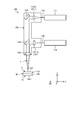
- FIG. 2 is an exemplary schematic configuration diagram of the laser welding apparatus of the embodiment.
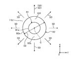
- FIG. 3 is an exemplary schematic view showing a beam (spot) of laser light on the surface of the welded portion of the vapor chamber of the embodiment.
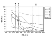
- FIG. 4 is a graph showing the light absorption rate of each metal material with respect to the wavelength of the laser light to be irradiated.
- FIG. 5 is an exemplary cross-sectional view of the welded portion of the embodiment.
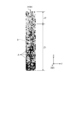
- FIG. 6 is an exemplary cross-sectional view showing a portion of the welded portion of the embodiment.
- FIG. 7 is a graph showing the experimental results of welding in the combination of the width of the welded portion and the diameter of the second spot when the first laser beam of the laser welding apparatus of the embodiment is irradiated alone.
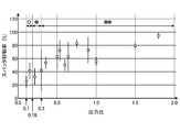
- FIG. 8 is a graph showing the correlation between the output ratio, which is the ratio of the power of the first laser beam to the power of the second laser beam by the laser welding apparatus of the embodiment, and the spatter suppression rate.
- FIG. 9 is an exemplary and schematic cross-sectional view of the welded portion of the embodiment, which is a cross-sectional view taken along the sweep direction and orthogonal to the surface.
- FIG. 10 is an exemplary and schematic cross-sectional view of a welded portion formed by a single irradiation of the first laser beam with the same power as in FIG.
- FIG. 9 as a reference example, and is a cross-sectional view taken along the sweep direction and with the surface. It is sectional drawing in the orthogonal cross section.
- FIG. 11 is an enlarged view of a part of FIG. 9.
- FIG. 12 is an explanatory view showing a case where the first reference line is applied to one position in the cross section of the welded portion of the embodiment.
- FIG. 13 is an explanatory view showing a case where a second reference line is applied to one position in the cross section of the welded portion of the embodiment.
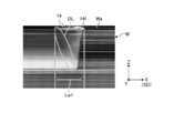
- FIG. 14 is an exemplary and schematic cross-sectional view of a cross section along the sweep direction of the welded portion of the embodiment and orthogonal to the surface, and is a cross-sectional view of the front end portion of the welded portion in the sweep direction.
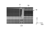
- FIG. 15 is an exemplary and schematic cross-sectional view in a cross section along the sweep direction of the weld formed by a single irradiation of the first laser beam with the same power as in FIG. 14 and orthogonal to the surface. It is a cross-sectional view of the front end portion of the welded portion in the sweep direction.
- direction X is represented by an arrow X
- direction Y is represented by an arrow Y
- direction Z is represented by an arrow Z.
- Direction X, direction Y, and direction Z intersect and are orthogonal to each other.
- FIG. 1 is a cross-sectional view of the vapor chamber 10 of the embodiment.
- the vapor chamber 10 has a flat shape that is thin in the Z direction and spreads in the X and Y directions. Further, the vapor chamber 10 has a rectangular shape such as a rectangular shape when viewed in the Z direction.
- the vapor chamber 10 includes a first member 11 and a second member 12.
- Both the first member 11 and the second member 12 are plate-shaped members made of a metal material.
- the first member 11 and the second member 12, respectively, can be made of a metal material having a relatively high thermal conductivity.
- the metal material is, for example, a copper-based metal material, an aluminum-based metal material, a nickel-based metal material, an iron-based metal material, a titanium-based metal material, or the like, and specifically, copper, a copper alloy, an aluminum, or an aluminum alloy. , Tin, nickel, nickel alloy, iron, stainless steel, titanium, titanium alloy, etc.
- the first member 11 and the second member 12 may be made of the same material or may be made of different materials.
- the first member 11 has a central portion 11a and a peripheral portion 11b.
- the central portion 11a has a bottom wall 11a1 and a side wall 11a2.
- the bottom wall 11a1 has a quadrangular shape when viewed in the Z direction.
- the side wall 11a2 extends from each of the four side edges of the bottom wall 11a1 in the opposite direction in the Z direction.
- the height of the side wall 11a2 in the Z direction is substantially constant.
- the bottom wall 11a1 and the four side walls 11a2 form a cavity recessed in the Z direction.
- the central portion 11a is an example of the first central portion.
- the peripheral edge portion 11b is arranged on the peripheral edge of the central portion 11a so as to surround the central portion 11a.
- the peripheral edge portion 11b has a quadrangular frame-like shape as an example.
- the peripheral edge portion 11b projects from the end portion of the side wall 11a2 on the side opposite to the bottom wall 11a1 in a direction intersecting the side wall 11a2 and away from the bottom wall 11a1.
- the peripheral edge portion 11b has a flat plate shape along the X direction and the Y direction.
- the peripheral edge portion 11b may also be referred to as a flange.
- the peripheral edge portion 11b is an example of the first peripheral edge portion.
- the first member 11 has two peripheral edges 11b extending in the X direction shown in FIG. 1 and two peripheral edges 11b extending in the Y direction not shown in FIG.
- the extending direction is the X direction
- the extending direction is the Y direction.
- the second member 12 has a central portion 12a and a peripheral portion 12b.
- the second member 12 has a quadrangular and plate-like shape as a whole, that is, a flat plate-like shape.
- the second member 12 overlaps with the first member 11 in the Z direction.
- the portion that overlaps the central portion 11a of the first member 11 in the Z direction is the central portion 12a
- the portion that overlaps the peripheral portion 11b of the first member 11 in the Z direction is the peripheral portion 12b. .. That is, the peripheral edge portion 12b is arranged on the peripheral edge of the central portion 12a so as to surround the central portion 12a.
- the second member 12 may also have a shape having a bottom wall and a side wall and forming a cavity recessed in a direction away from the bottom wall 11a1 of the first member 11, like the first member 11.
- the central portion 12a is an example of the second central portion
- the peripheral portion 12b is an example of the second peripheral portion.
- the second member 12 has two peripheral edges 12b extending in the X direction shown in FIG. 1 and two peripheral edges 12b extending in the Y direction not shown in FIG.
- the extending direction is the X direction
- the extending direction is the Y direction.
- a storage chamber R is provided between the central portion 11a and the central portion 12a.
- the refrigerant 13 is stored in the storage chamber R.
- the vapor chamber 10 is provided over a high temperature portion and a low temperature portion.
- the high temperature part is, for example, a heating element such as a CPU (central processing unit), and the low temperature part is, for example, a heat sink such as a heat sink.
- the refrigerant 13 changes from the liquid phase to the gas phase by receiving heat from the high temperature portion, and changes from the gas phase to the liquid phase by dissipating heat to the low temperature portion.
- the refrigerant 13 that has become a gas in the region adjacent to the high temperature portion in the accommodation chamber R moves in the accommodation chamber R to the region adjacent to the low temperature portion in the accommodation chamber R in the state of the gas. Further, the refrigerant 13 that has become liquid in the region adjacent to the low temperature portion in the accommodation chamber R moves in the accommodation chamber R to the region adjacent to the high temperature portion in the accommodation chamber R due to the capillary phenomenon.
- the vapor chamber 10 can function as a cooling mechanism for the high temperature portion.
- the peripheral edge portion 11b and the peripheral edge portion 12b are joined via a welded portion 14 formed by laser welding.
- the laser beam L is emitted toward the surface 11b1 of the peripheral edge portion 11b in the direction opposite to the Z direction.
- the surface 11b1 is an end face of the peripheral edge portion 11b in the Z direction.
- the welded portion 14 extends from the surface 11b1 toward the surface 12b1 of the peripheral edge portion 12b.
- the front surface 12b1 is an end surface of the peripheral edge portion 12b in the direction opposite to the Z direction, and may also be referred to as a back surface.
- the welded portion 14 extends from the surface 11b1 to the intermediate portion of the peripheral edge portion 12b in the Z direction, but may penetrate the peripheral edge portion 11b and the peripheral edge portion 12b.
- the surface 11b1 is an example of the first surface.
- the welded portion 14 is provided on each peripheral edge portion 11b (12b).
- the laser beam L is swept along the extending direction of the peripheral edge portion 11b. Therefore, the welded portion 14 extends linearly along the surface 11b1.
- the welded portion 14 has two welded portions 14 extending in the X direction shown in FIG. 1 and two welded portions 14 extending in the Y direction not shown in FIG. ..
- the extension direction is the X direction
- the extension direction is the Y direction.
- FIG. 2 is a schematic configuration diagram of a laser welding apparatus 100 that welds peripheral portions 11b and 12b.
- the laser welding device 100 includes a laser device 111, a laser device 112, an optical head 120, and an optical fiber 130.
- Each of the laser devices 111 and 112 is provided with a laser oscillator, and as an example, it is configured to be able to output a laser beam having a power of several kW. Further, the laser devices 111 and 112 may be configured to include, for example, a plurality of semiconductor laser elements inside and to output a multimode laser beam having a power of several kW as the total output of the plurality of semiconductor laser elements. good. Further, the laser devices 111 and 112 may be provided with various laser light sources such as a fiber laser, a YAG laser, and a disk laser.
- the laser device 111 outputs the first laser beam having a wavelength of 800 [nm] or more and 1200 [nm] or less.
- the laser device 111 is an example of the first laser device.
- the laser device 112 outputs a second laser beam having a wavelength of 500 [nm] or less.
- the laser device 112 is an example of a second laser device.
- the optical fiber 130 guides the laser light output from the laser devices 111 and 112 to the optical head 120, respectively.
- the optical head 120 is an optical device for irradiating the laser beam input from the laser devices 111 and 112 toward the processing target.
- the optical head 120 includes a collimating lens 121, a condenser lens 122, a mirror 123, and a filter 124.
- the collimating lens 121, the condenser lens 122, the mirror 123, and the filter 124 may also be referred to as optical components.
- the optical head 120 is configured so that the relative position with respect to the peripheral portions 11b and 12b can be changed in order to sweep the laser light L while irradiating the peripheral portions 11b and 12b to be processed with the laser light L. ..
- the relative movement of the optical head 120 and the peripheral portions 11b and 12b can be realized by the movement of the optical head 120, the movement of the processing target, or the movement of both the optical head 120 and the processing target.
- optical head 120 may be configured to be able to sweep the laser beam L at the peripheral edges 11b and 12b by having a galvanometer mirror or the like (not shown).
- the collimating lens 121 (121-1, 121-2) collimates the laser beam input via the optical fiber 130, respectively.
- the collimated laser beam becomes parallel light.
- the mirror 123 reflects the first laser beam that has become parallel light by the collimating lens 121-1.
- the first laser beam reflected by the mirror 123 travels in the opposite direction to the Z direction and heads toward the filter 124.
- the mirror 123 is not required in the configuration in which the first laser beam is input to the optical head 120 so as to travel in the direction opposite to the Z direction.
- the filter 124 is a high-pass filter that transmits the first laser beam and reflects the second laser beam without transmitting it.
- the first laser beam passes through the filter 124, travels in the opposite direction in the Z direction, and travels toward the condenser lens 122.
- the filter 124 reflects the second laser beam that has become parallel light by the collimating lens 121-2.
- the second laser beam reflected by the filter 124 travels in the opposite direction to the Z direction and heads toward the condenser lens 122.
- the condensing lens 122 condenses the first laser light and the second laser light as parallel light, and irradiates the peripheral portions 11b and 12b as the processing target as the laser light L (output light).
- the optical head 120 may have a beam shaper (not shown) such as a DOE (diffractive optical element).
- a beam shaper such as a DOE (diffractive optical element).
- the optical head 120 is provided after the collimating lens 121-1 to adjust the beam shape of the first laser beam, or is provided after the collimating lens 121-2 to adjust the beam shape of the second laser beam.
- a beam shaper, a beam shaper provided after the filter 124 and adjusting the beam shapes of the first laser beam and the second laser beam, and the like can be provided.
- FIG. 3 is a schematic view showing a beam (spot) of the laser beam L irradiated on the surface 11b1.
- the beam of the laser beam L includes the beam B1 of the first laser beam and the beam B2 of the second laser beam.
- the beam B1 and the beam B2 overlap each other, the beam B2 is larger (wider) than the beam B1, and the outer edge B2a of the beam B2 surrounds the outer edge B1a of the beam B1. , Is formed.
- the beam B1 is an example of the first irradiation region
- the beam B2 is an example of the second irradiation region.
- the arrow SD shown in FIG. 3 indicates the sweep direction.
- the shape of the beam (spot) of the laser beam L is the same for any sweep direction SD. .. Therefore, when a moving mechanism for relatively moving the optical head 120 and the vapor chamber 10 for sweeping the laser beam L on the surface 11b1, the moving mechanism should have at least a relatively relatively translatable mechanism. However, the relatively rotatable mechanism may be omitted.
- FIG. 4 is a graph showing the light absorption rate of each metal material with respect to the wavelength of the laser beam L to be irradiated.
- the horizontal axis of the graph of FIG. 4 is the wavelength, and the vertical axis is the absorption rate.
- FIG. 3 shows the relationship between wavelength and absorption rate for aluminum (Al), copper (Cu), gold (Au), nickel (Ni), silver (Ag), tantalum (Ta), and titanium (Ti). It is shown.
- a blue or green laser beam (second laser) is used rather than using a general infrared (IR) laser beam (first laser beam). It can be understood that the energy absorption rate is higher when light) is used. This feature becomes remarkable in copper (Cu), gold (Au), and the like.
- the wavelength of the first laser light, the wavelength of the second laser light, and the peripheral portion so that the absorption rate of the peripheral portions 11b and 12b with respect to the second laser light is higher than the absorption rate of the peripheral portions 11b and 12b with respect to the first laser light.
- the materials of 11b and 12b that is, the materials of the first member 11 and the second member 12 are selected.
- the sweep direction is the sweep direction SD1 indicated by the thick solid line in FIG. 3
- the peripheral portions 11b and 12b are welded by sweeping the spot of the laser beam L (hereinafter, referred to as the welded portion).
- the second laser beam is irradiated by the region B2f of the beam B2 of the second laser beam located in front of the SD in FIG.
- the welded portion is irradiated with the beam B1 of the first laser beam, and then the second laser beam is irradiated again by the region B2b of the beam B2 of the second laser beam located behind the sweep direction SD1.
- a heat conduction type melting region is first generated by irradiation with a second laser beam having a high absorption rate in the region B2f. After that, a deeper keyhole-type molten region is generated in the welded portion by irradiation with the first laser beam.
- the required depth is obtained by the first laser beam having a lower power than in the case where the heat conduction type melting region is not formed.
- a molten region can be formed.
- the welded portion is changed in a molten state by irradiation with a second laser beam having a high absorption rate in the region B2b.
- the wavelength of the second laser beam is preferably 550 nm or less, and more preferably 500 nm or less.
- the vapor chamber 10 to be processed is set so that the laser beams L are irradiated to the peripheral portions 11b and 12b in which the laser light L is substantially adhered to each other. Then, the laser beam L and the peripheral edges 11b and 12b are relatively moved in a state where the peripheral edges 11b and 12b in which the laser beams L including the beams B1 and the beam B2 are overlapped are irradiated. As a result, the laser beam L moves (sweeps) in the sweep direction SD on the surface 11b1 while being irradiated on the surface 11b1. The portion irradiated with the laser beam L is melted and then solidified as the temperature decreases, so that the peripheral portions 11b and 12b are welded, whereby the refrigerant 13 is sealed in the accommodation chamber R. ..
- FIG. 5 is a cross-sectional view of a welded portion 14 formed on a machining target W equivalent to the peripheral portions 11b and 12b of the vapor chamber 10.
- FIG. 5 is a cross-sectional view at the same position as in FIG. 1, which is perpendicular to the sweep direction SD (X direction) and along the thickness direction (Z direction).
- the welded portion 14 extends in the sweep direction SD, that is, in the direction perpendicular to the paper surface of FIG.
- FIG. 5 shows a cross section of the welded portion 14 formed on the processing target W, which is a single copper plate having a thickness of 2 [mm].
- the form of the welded portion 14 formed of a plurality of plate-shaped metal materials stacked in the thickness direction (Z direction) is substantially the same as the form of the welded portion formed of one metal material having the same thickness. Can be presumed to be.
- the welded portion 14 has a weld metal 14a extending from the surface 11b1 in the opposite direction in the Z direction, and a heat-affected zone 14b located around the weld metal 14a. ..
- the weld metal 14a is a portion that is melted by irradiation with the laser beam L and then solidified.
- the weld metal 14a can also be referred to as a melt-solidified portion.
- the heat-affected zone 14b is a portion where the base material of the processing target W is thermally affected and is not melted.
- the width of the weld metal 14a along the Y direction becomes narrower as the distance from the surface 11b1 increases. That is, the cross section of the weld metal 14a has a tapered shape that narrows in the direction opposite to the Z direction.
- the weld metal 14a includes a first portion 14a1 separated from the surface 11b1 and a second portion 14a2 between the first portion 14a1 and the surface 11b1. There was found.
- the first portion 14a1 is a portion obtained by melting the keyhole type by irradiation with the first laser beam
- the second portion 14a2 is a region located behind the sweep direction SD1 in the beam B2 of the second laser beam. It is a part obtained by melting by irradiation of B2b.
- the crystal grain size is different between the first site 14a1 and the second site 14a2, specifically, the X direction (sweep direction). It was found that the average cross-sectional area of the crystal grains at the second site 14a2 was larger than the average cross-sectional area of the crystal grains at the first site 14a1 in the cross section orthogonal to SD).
- the inventors have found that when the welded portion is irradiated with only the beam B1 of the first laser beam, that is, when the region B2b located behind the sweep direction SD1 in the beam B2 is not irradiated, the second It was confirmed that the site 14a2 was not formed and the first site 14a1 extended deeply from the surface 11b1 in the opposite direction to the Z direction. That is, in the present embodiment, the second portion 14a2 is formed near the surface 11b1 by the irradiation of the region B2b located behind the sweep direction SD1 in the beam B2, so that the first portion 14a1 is the said. It can be presumed that the second portion 14a2 is formed at a position opposite to the surface 11b1, in other words, at a position separated from the surface 11b1 in the opposite direction in the Z direction.
- FIG. 6 is a cross-sectional view showing a part of the welded portion 14.
- FIG. 6 shows the boundaries of the crystal grains obtained by the EBSD method.
- crystal grains A having a crystal grain size of 13 [ ⁇ m] or less are painted black. Note that 13 [ ⁇ m] is not a threshold value of physical characteristics, but a threshold value set for analysis of the experimental results.
- the crystal grains A are relatively abundant in the first portion 14a1 and relatively abundant in the second portion 14a2. That is, the average cross-sectional area of the crystal grains in the second site 14a2 is larger than the average cross-sectional area of the crystal grains in the first site 14a1.
- the inventors have found that the average cross-sectional area of the crystal grains in the second site 14a2 is 1.8 times or more the average cross-sectional area of the crystal grains in the first site 14a1. It was confirmed.
- such relatively small crystal grains A are densely packed in a state of being elongated in the Z direction at a position separated from the surface 11b1 in the Z direction. There is. Further, from the analysis at a plurality of locations where the positions in the X direction (sweep direction SD) are different, it is confirmed that the region where the crystal grains A are densely extends also extends to the sweep direction SD. Since the welding is performed while sweeping, it can be estimated that crystals are formed in the same shape in the sweep direction SD.
- first region Z1 and second region Z2 may be designated as the first region 14a1 and the second region 14a2, respectively.
- the first region Z1 and the second region Z2 are square regions extending in the Z direction with a width wm (equal width in the Y direction) in a cross section orthogonal to the sweep direction SD, and the second region Z2.
- the first region Z1 is a region deeper than the depth d, in other words, a region opposite to the surface 11b1 with respect to the position of the depth d. can do.
- the width wm is, for example, 1/3 of the width wb (average value of the bead width) on the surface 11b1 of the weld metal 14a, and the depth d (height, thickness) of the second region Z2 is, for example, the width wb. Can be 1/2 of.
- the depth of the first region Z1 can be, for example, three times the depth d of the second region Z2.
- the inventors According to an experimental analysis of a plurality of samples, the inventors have found that in such a setting of the first region Z1 and the second region Z2, the average value of the cross-sectional areas of the crystal grains in the second region Z2 is in the first region Z1. It was confirmed that it was larger than the average value of the cross-sectional area of the crystal grains and was 1.8 times or more. Such a relationship between the size of the crystal grains in the first region Z1 and the second region Z2 is considered to be a factor for realizing a strong welding strength in the processing target W, and such discrimination is also made by welding the weld metal. It can be evidence that the first site 14a1 and the second site 14a2 are formed at 14a.
- the total thickness T (see FIG. 1) of the peripheral portions 11b and 12b as the processing target W by laser welding of the present embodiment is 0.05 [mm] or more. It was found that the same result can be obtained when there is and it is 2.0 [mm] or less.
- Each of the beam B1 and the beam B2 has, for example, a Gaussian-shaped power distribution in the radial direction of the cross section orthogonal to the optical axis direction of the beam.
- the power distribution of the beams B1 and B2 is not limited to the Gaussian shape.
- the diameter of the circle representing the beams B1 and B2 is the beam diameter of each beam B1 and B2.
- Beam diameter of each beam B1, B2 includes a peak of the beam is defined as the diameter of the region of 1 / e 2 or more of the intensity of the peak intensity.
- the length of a region having an intensity of 1 / e 2 or more of the peak intensity in the direction perpendicular to the sweep direction SD can be defined as the beam diameter.
- the beam diameter on the surface 11b1 is referred to as a spot diameter.
- FIG. 7 is a diagram showing the experimental results of welding by combining the width wb (bead width) of the welded portion when the beam B1 is irradiated alone and the spot diameter D2 (outer diameter, see FIG. 3) of the beam B2.
- ⁇ indicates that the number of spatters and blow holes is very small (excellent)
- ⁇ indicates that the number of spatters and blow holes is small (good)
- ⁇ indicates that the number of spatters and blow holes is small.
- some other inconvenience occurs (possible) such as a large energy loss is shown.
- excellent indicates the case where the number of blow holes per unit length (for example, 1 [cm]) of the linear welded portion is 1 or less, and "good” and “possible”. ”Indicates a case where the number of blow holes per unit length of the welded portion is 2 or more and less than 5. Further, in this experiment, the wavelength of the first laser beam is 1070 [nm] and the output is 1 [kW], the wavelength of the second laser beam is 450 [nm] and the output is 400 [W]. there were.
- the spatter suppression rate Rs is defined as the following equation (2).
- Rs 1-Nh / Nir ⁇ ⁇ ⁇ (2)
- Nh is the number of spatters generated in a predetermined area when both the first laser beam and the second laser beam are irradiated
- Nir is only the first laser beam with the same power as when measuring Nh.
- FIG. 8 shows the results of conducting experiments a plurality of times at each output ratio.
- the line segment corresponding to the output ratio indicates the range of variation in the spatter suppression rate in the experimental results of multiple samples (at least 3 samples or more) at the output ratio, and ⁇ indicates the median value of the spatter suppression rate for each output ratio.
- the output ratio Rp is preferably 0.1 or more and less than 0.18 ( ⁇ ), and 0.18 or more and less than 0.3. It was found that the above case is more preferable ( ⁇ ), and the case of 0.3 or more and 2 or less is more preferable ( ⁇ ⁇ ).
- the inventors conducted experiments on a plurality of samples at different sweep velocities, and found that the occurrence of spatter and blow holes differs depending on the sweep velocities.
- the sweep rate is preferably 50 [mm / s] or more, and more preferably 100 [mm / s] or more. found.
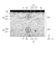
- FIG. 9 is a cross-sectional view of the welded portion 14 formed by irradiation of both the first laser beam and the second laser beam in a cross section along the sweep direction and orthogonal to the surface Wa.
- FIG. 10 is a cross-sectional view of the welded portion 14 formed by a single irradiation of the first laser beam with the same power as in FIG. 9 as a reference example in a cross section along the sweep direction and orthogonal to the surface Wa. be.
- the conditions other than the single irradiation of the first laser beam in the example of FIG. 10 are set in the same manner as in the case of the example of FIG.
- the experiments shown in FIGS. 9 and 10 were carried out on the W to be processed as one metal material. It has been confirmed that when the first member 11 and the second member 12 are in close contact with each other, substantially the same result as this experimental result can be obtained.
- the front surface Wa corresponds to the front surface 11b1
- the back surface Wb corresponds to the front surface 12b1.
- FIG. 11 is an enlarged view of a part of FIG. 9.
- the depth from the surface Wa It was found that the orientations (longitudinal direction, growth direction) of the crystal grains differed according to the above. This is obtained by melting the third portion 14a3 obtained by the keyhole-type melting by the irradiation of the first laser beam and the region B2b located behind the sweep direction in the beam B2 of the second laser beam.
- the third portion 14a3 is a portion located away from the surface Wa and corresponds to the above-mentioned first portion 14a1.
- the fourth part 14a4 is a part located between the third part 14a3 and the surface Wa, and is a part corresponding to the above-mentioned second part 14a2.
- JIS G 0551: 2020 A.M. 2 Based on the cutting method, an index showing the direction (longitudinal direction) of the crystal grains in each part in the welded part 14 was defined.
- first reference line R1 and second reference line R2 including two linear test lines orthogonal to each other are used in the cross-sectional image.
- first reference line R1 is shown by a solid line
- second reference line R2 is shown by a broken line.
- the first reference line R1 has two diameters orthogonal to each other of the reference circle R0 as the straight line test lines L11 and L12, and one straight line test line L11 is in the X direction (sweep direction) along the surface Wa.
- the other linear test line L12 extends in the Z direction orthogonal to the surface Wa.
- the second reference line R2 has two diameters orthogonal to each other of the same reference circle R0 as the first reference line R1 as the straight line test lines L21 and L22, and one straight line test line L21 is X.
- the other linear test line L12 Extending in the direction between the direction and the Z direction, the other linear test line L12 is in the direction between the opposite direction of the X direction and the Z direction, or the direction between the opposite direction of the Z direction and the X direction. , Is extending.
- the angle difference between the linear test line L11 and the linear test line L21 is 45 ° or 135 °
- the angular difference between the linear test line L12 and the linear test line L22 is 45 ° or 135 °.
- the length of the diameter of the reference circle R0 that is, the length of the linear test lines L11, L12, L21, and L22 is, for example, a length corresponding to 200 [ ⁇ m] (a predetermined length). However, it can be appropriately set according to the size of the crystal grains.
- the number of crystal grains can also be referred to as the number of grain boundaries. Further, in the formula (3-2), when (N22 / N21) is (N21 / N22) or more, max (N22 / N21, N21 / N22) is (N22 / N21), and (N22 / N21). When is less than (N21 / N22), max (N22 / N21, N21 / N22) is (N21 / N22). In the actual measurement, in the micrograph of the XZ cross section taken at 50 times, the above measurement can be performed at an arbitrary predetermined location or more, for example, 10 or more locations, and the average values thereof can be Rb1 and Rb2, respectively. .. When any one of N11, N12, N21, and N22 becomes 0 at a certain point P in the welded portion 14, the number of grain boundaries at the point P does not have to be used for the calculation of Rb1 and Rb2.
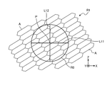
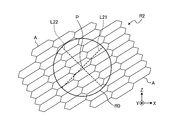
- FIGS. 12 and 13 are schematics showing a case where the first reference line R1 is applied (FIG. 12) and a case where the second reference line R2 is applied to one point P in the cross section of the welded portion 14 (FIG. 13).
- the number of crystal grains A (grain boundaries) intersecting the linear test lines L11, L12, L21, and L22 is different.
- the grain boundary number N21 is smaller than the other grain boundary numbers N11, N12, and N22. Therefore, the point P shown in the examples of FIGS.
- the second grain boundary number ratio Rb2 is higher than the first grain boundary number ratio Rb1.
- the first grain boundary number ratio Rb1 is relatively high and the second grain boundary is second. It becomes larger than the grain boundary number ratio Rb2.
- the second grain boundary number ratio Rb2 is relatively high and the second grain boundary ratio Rb2 is relatively high. It becomes larger than the grain boundary number ratio Rb1.
- the first grain boundary number ratio Rb1 at each point P in the fourth site 14a4 is lower than the first grain boundary number ratio Rb1 at each point P in the third site 14a3.
- the second grain boundary number ratio Rb2 at each point P in the fourth site 14a4 is higher than the second grain boundary number ratio Rb2 at each point P in the third site 14a3.
- the first grain boundary number ratio Rb1 is higher than the second grain boundary number ratio Rb2, and at each point P in the fourth site 14a4, the second grain boundary number. It was found that the ratio Rb2 was higher than the first grain boundary number ratio Rb1.
- first grain boundary ratio Rb1 and the second grain boundary ratio Rb2 in the welded portion 14 is considered to be a factor for realizing a strong welding strength in the work target W.
- the weld metal 14a is the first portion 14a1 located apart from the surface 11b1 (first surface) in the thickness direction (opposite direction in the Z direction). It has a second site 14a2, which is located between the first site 14a1 and the surface 11b1 and has a larger average cross-sectional area of crystal grains than the first site 14a1.
- the average value of the cross-sectional areas of the crystal grains contained in the second portion 14a2 is included in the first portion 14a1. It is 1.8 times or more the average value of the cross-sectional area of the crystal grains.
- such a welded portion 14 sweeps the beam of the laser beam L having the beam B1 of the first laser beam and the beam B2 of the second laser beam to the surface 11b1 as shown in FIG. It was obtained by irradiating the SD while sweeping. Further, as described above, the inventors have experimentally confirmed that the spatter can be reduced in the welding by irradiating the beam of the laser beam L as shown in FIG. This is because, as described above, the peripheral edges 11b and 12b formed by the beam B2 and the beam B1 are formed by preheating the peripheral edges 11b and 12b by the region B2f of the beam B2 before the beam B1 arrives. It can be presumed that this is because the molten pool is more stable.
- the present embodiment for example, it is possible to obtain a vapor chamber 10 provided with a welded portion 14 having a higher welding quality with less spatter. Further, according to the present embodiment, for example, the power of the first laser beam can be made lower, and the relative rotation between the optical head 120 and the vapor chamber 10 becomes unnecessary. ..
- the first member 11 and the second member 12 are among a copper-based metal material, an aluminum-based metal material, a nickel-based metal material, an iron-based metal material, and a titanium-based metal material, respectively. Made of either.
- the vapor chamber 10 having the welded portion 14 of the present embodiment can be configured when the first member 11 and the second member 12 are each made of any of the above materials.
- the total of the thickness of the peripheral edge portion 11b (first peripheral edge portion) and the thickness of the peripheral edge portion 12b (second peripheral edge portion) is 0.05 [mm] or more and 2.0 [mm]. It is as follows.
- the vapor chamber 10 having the welded portion 14 of the present embodiment can be configured when the total of the thickness of the peripheral edge portion 11b and the thickness of the peripheral edge portion 12b is within the above range.
- the laser beam L is applied to the surface 11b1 so that the spot moves relatively along the peripheral edge portion 11b in a state where the peripheral edge portion 11b and the peripheral edge portion 12b are overlapped with each other. By irradiating, the peripheral edge portion 11b and the peripheral edge portion 12b are welded.
- the laser light L includes a first laser light having a wavelength of 800 [nm] or more and 1200 [nm] or less, and a second laser light having a wavelength of 550 [nm] or less.
- the beam B2 (second irradiation region) of the second laser light is wider than the beam B1 (first irradiation region) of the first laser light, and the outer edge of the beam B2.
- B2a (second outer edge) surrounds the outer edge B1a (first outer edge) of the beam B1.
- a vapor chamber 10 provided with a welded portion 14 having a higher welding quality with less spatter it is possible to obtain a vapor chamber 10 provided with a welded portion 14 having a higher welding quality with less spatter. Further, for example, the power of the first laser beam can be made lower, and the relative rotation between the optical head 120 and the vapor chamber 10 becomes unnecessary.
- FIG. 14 is a cross-sectional view of the welded portion 14 along the sweep direction SD of the embodiment and in a cross section orthogonal to the surface Wa, and is a cross-sectional view of the front end portion of the welded portion 14 in the sweep direction SD.
- FIG. 15 is a cross-sectional view taken along the sweep direction SD of the welded portion 14 formed by single irradiation of the first laser beam with the same power as in FIG. 14 and in a cross section orthogonal to the surface Wa. It is a cross-sectional view of the front end portion of the welded portion 14 in the sweep direction SD.
- the contour of the molten pool (welded portion 14) is visualized by image processing.
- the molten pool formed in the processing with the hybrid laser that irradiates the first laser beam and the second laser beam of the present embodiment shown in FIG. 14 is a fiber laser that irradiates only the first laser beam shown in FIG.
- the tail is longer behind the sweep direction SD as compared with the molten pool formed by the processing in.
- the front portion 14f of the molten pool (welded portion 14) of the present embodiment projects in front of the sweep direction SD.
- the length Lw1 see FIG.
- the molten pool formed in the machining with the hybrid laser in the sweep direction SD is the length Lw2 in the sweep direction SD of the molten pool formed in the machining with the fiber laser (FIG. 14). It is longer than (see 15). That is, in the processing with the hybrid laser, the molten pool is larger than the processing with the fiber laser. According to the hybrid laser processing that irradiates the first laser beam and the second laser beam of the present embodiment, the molten pool expands and the internal thermal convection is more stabilized by the irradiation of the second laser beam (blue laser beam). At the same time, the opening of the keyhole is enlarged and the vapor pressure at the time of evaporation is more easily escaped to the outside. Therefore, the generation of spatter is suppressed and a stable molten pool can be obtained as compared with the single irradiation of the first laser beam. Can be estimated.
- the surface area of the molten pool may be adjusted by sweeping by known wobbling, weaving, output modulation, or the like.
- the peripheral portion may have a thin layer of another metal on the surface of the metal, such as a plated metal plate.
- the beam of the first laser beam may be partially located outside the beam of the second laser beam.
- the present invention can be used in a vapor chamber and a method for manufacturing a vapor chamber.
Landscapes
- Engineering & Computer Science (AREA)
- Physics & Mathematics (AREA)
- Optics & Photonics (AREA)
- Mechanical Engineering (AREA)
- Plasma & Fusion (AREA)
- Life Sciences & Earth Sciences (AREA)
- Sustainable Development (AREA)
- Thermal Sciences (AREA)
- General Engineering & Computer Science (AREA)
- Laser Beam Processing (AREA)
Abstract
ベーパチャンバは、例えば、第一中央部と当該第一中央部の周縁の第一周縁部とを有した金属製の板状の第一部材と、第一中央部との間に冷媒の収容部を形成する第二中央部と当該第二中央部の周縁に位置し第一周縁部と厚さ方向に重なった第二周縁部とを有した金属製の板状の第二部材と、第一周縁部の第二周縁部とは反対側の第一表面に沿って延び第一周縁部と第二周縁部とを溶接する線状の溶接部と、を備え、溶接部は、第一表面から厚さ方向に延びた溶接金属と、溶接金属の周囲に位置される熱影響部と、を有し、前記溶接金属は、第一表面から厚さ方向に離れて位置された第一部位と、当該第一部位と第一表面との間に位置され第一部位よりも溶接部の延び方向と直交する断面における結晶粒の断面積の平均値が大きい第二部位と、を有する。
Description
本発明は、ベーパチャンバおよびベーパチャンバの製造方法に関する。
従来、重ねられた二つの板状の金属部材の間に冷媒を収容する収容室を設け、当該二つの金属部材の周縁部を溶接することにより冷媒を封止したベーパチャンバが知られている(例えば、特許文献1)。このようなベーパチャンバは、ヒートパイプとも呼ばれている。
このように周縁部が溶接されることにより冷媒が封止されたベーパチャンバでは、例えば、スパッタが少ないなど、より溶接品質の高い溶接部を備えたベーパチャンバが得られれば、有益である。
そこで、本発明の課題の一つは、例えば、より溶接品質の高い溶接部を備えたベーパチャンバおよび当該ベーパチャンバの製造方法を得ること、である。
本発明のベーパチャンバにあっては、例えば、冷媒と、金属材料で作られ、第一中央部と、当該第一中央部の周縁の第一周縁部と、を有した板状の第一部材と、金属材料で作られ、前記第一中央部との間に前記冷媒の収容部を形成する第二中央部と、当該第二中央部の周縁に位置し前記第一周縁部と厚さ方向に重なった第二周縁部と、を有した板状の第二部材と、前記第一周縁部の前記第二周縁部とは反対側の第一表面に沿って延び、前記第一周縁部と前記第二周縁部とを溶接する線状の溶接部と、を備え、前記溶接部は、前記第一表面から前記厚さ方向に延びた溶接金属と、前記溶接金属の周囲に位置される熱影響部と、を有し、前記溶接金属は、前記第一表面から前記厚さ方向に離れて位置された第一部位と、当該第一部位と前記第一表面との間に位置され前記第一部位よりも前記溶接部の延び方向と直交する断面における結晶粒の断面積の平均値が大きい第二部位と、を有する。
前記ベーパチャンバでは、前記第二部位に含まれる結晶粒の断面積の平均値は、前記第一部位に含まれる結晶粒の断面積の平均値の1.8倍以上であってもよい。
本発明のベーパチャンバにあっては、例えば、冷媒と、金属材料で作られ、第一中央部と、当該第一中央部の周縁の第一周縁部と、を有した板状の第一部材と、金属材料で作られ、前記第一中央部との間に前記冷媒の収容部を形成する第二中央部と、当該第二中央部の周縁に位置し前記第一周縁部と厚さ方向に重なった第二周縁部と、を有した板状の第二部材と、前記第一周縁部の前記第二周縁部とは反対側の第一表面に沿って延び、前記第一周縁部と前記第二周縁部とを溶接する線状の溶接部と、を備え、前記溶接部は、前記第一表面から前記厚さ方向に延びた溶接金属と、前記溶接金属の周囲に位置される熱影響部と、を有し、第一粒界数比率を次の式(3-1)
Rb1=N12/N11 ・・・(3-1)
(ここに、Rb1は、第一粒界数比率、N11は、前記第一表面と直交しかつ前記溶接部の延び方向に沿った試験断面において、前記第一表面に沿った所定の長さの直線試験線と交差した粒界数であり、N12は、前記試験断面において、前記第一表面と直交した方向に延びた前記所定の長さの直線試験線と交差した粒界数である。)と表した場合に、前記溶接金属は、前記第一表面に対して前記厚さ方向に離れて位置された第三部位と、当該第三部位と前記第一表面との間に位置され前記第一粒界数比率が前記第三部位の前記第一粒界数比率よりも低い第四部位と、を有する。
Rb1=N12/N11 ・・・(3-1)
(ここに、Rb1は、第一粒界数比率、N11は、前記第一表面と直交しかつ前記溶接部の延び方向に沿った試験断面において、前記第一表面に沿った所定の長さの直線試験線と交差した粒界数であり、N12は、前記試験断面において、前記第一表面と直交した方向に延びた前記所定の長さの直線試験線と交差した粒界数である。)と表した場合に、前記溶接金属は、前記第一表面に対して前記厚さ方向に離れて位置された第三部位と、当該第三部位と前記第一表面との間に位置され前記第一粒界数比率が前記第三部位の前記第一粒界数比率よりも低い第四部位と、を有する。
本発明のベーパチャンバにあっては、例えば、冷媒と、金属材料で作られ、第一中央部と、当該第一中央部の周縁の第一周縁部と、を有した板状の第一部材と、金属材料で作られ、前記第一中央部との間に前記冷媒の収容部を形成する第二中央部と、当該第二中央部の周縁に位置し前記第一周縁部と厚さ方向に重なった第二周縁部と、を有した板状の第二部材と、前記第一周縁部の前記第二周縁部とは反対側の第一表面に沿って延び、前記第一周縁部と前記第二周縁部とを溶接する線状の溶接部と、を備え、前記溶接部は、前記第一表面から前記厚さ方向に延びた溶接金属と、前記溶接金属の周囲に位置される熱影響部と、を有し、第二粒界数比率を次の式(3-2)
Rb2=max(N22/N21,N21/N22) ・・・(3-2)
(ここに、Rb2は、第二粒界数比率、N21は、前記第一表面と直交しかつ前記溶接部の延び方向に沿った試験断面において、前記第一表面に沿う方向および前記第一表面と直交する方向の間の第一方向に延びた所定の長さを有する直線試験線と交差した粒界数であり、N22は、前記試験断面おいて、前記第一方向と直交した第二方向に延びた前記所定の長さを有する直線試験線と交差した粒界数であり、max(N22/N21,N21/N22)は、(N22/N21)が(N21/N22)以上である場合は(N22/N21)とし、(N22/N21)が(N21/N22)未満である場合は(N21/N22)とする。)と表した場合に、前記溶接金属は、前記第一表面に対して前記厚さ方向に離れて位置された第三部位と、当該第三部位と前記第一表面との間に位置され前記第二粒界数比率が前記第三部位の前記第二粒界数比率よりも高い第四部位と、を有する。
本発明のベーパチャンバにあっては、例えば、冷媒と、金属材料で作られ、第一中央部と、当該第一中央部の周縁の第一周縁部と、を有した板状の第一部材と、金属材料で作られ、前記第一中央部との間に前記冷媒の収容部を形成する第二中央部と、当該第二中央部の周縁に位置し前記第一周縁部と厚さ方向に重なった第二周縁部と、を有した板状の第二部材と、前記第一周縁部の前記第二周縁部とは反対側の第一表面に沿って延び、前記第一周縁部と前記第二周縁部とを溶接する線状の溶接部と、を備え、前記溶接部は、前記第一表面から前記厚さ方向に延びた溶接金属と、前記溶接金属の周囲に位置される熱影響部と、を有し、第一粒界数比率を次の式(3-1)
Rb1=N12/N11 ・・・(3-1)
(ここに、Rb1は、第一粒界数比率、N11は、前記第一表面と直交しかつ前記溶接部の延び方向に沿った試験断面において、前記第一表面に沿った所定の長さの直線試験線と交差した粒界数であり、N12は、前記試験断面において、前記第一表面と直交した方向に延びた前記所定の長さの直線試験線と交差した粒界数である。)と表し、かつ、第二粒界数比率Rb2を次の式(3-2)
Rb2=max(N22/N21,N21/N22) ・・・(3-2)
(ここに、Rb2は、第二粒界数比率、N21は、前記第一表面と直交しかつ前記溶接部の延び方向に沿った試験断面において、前記第一表面に沿う方向および前記第一表面と直交する方向の間の第一方向に延びた所定の長さを有する直線試験線と交差した粒界数であり、N22は、前記試験断面おいて、前記第一方向と直交した第二方向に延びた前記所定の長さを有する直線試験線と交差した粒界数であり、max(N22/N21,N21/N22)は、(N22/N21)が(N21/N22)以上である場合は(N22/N21)とし、(N22/N21)が(N21/N22)未満である場合は(N21/N22)とする。)と表した場合に、前記溶接金属は、前記第一表面に対して前記厚さ方向に離れて位置された第三部位と、当該第三部位と前記第一表面との間に位置され前記第一粒界数比率が前記第三部位の前記第一粒界数比率よりも低くかつ前記第二粒界数比率が前記第三部位の前記第二粒界数比率よりも高い第四部位と、を有する。
前記ベーパチャンバでは、前記第一部材および前記第二部材は、それぞれ、銅系金属材料、アルミニウム系金属材料、ニッケル系金属材料、鉄系金属材料、およびチタン系金属材料のうちのいずれかで作られてもよい。
前記ベーパチャンバでは、例えば、前記第一周縁部の厚さと前記第二周縁部の厚さとの合計が、0.05[mm]以上2.0[mm]以下であってもよい。
また、本発明のベーパチャンバの製造方法は、例えば、冷媒と、金属材料で作られ、第一中央部と、当該第一中央部の周縁の第一周縁部と、を有した板状の第一部材と、金属材料で作られ、前記第一中央部との間に前記冷媒の収容部を形成する第二中央部と、当該第二中央部の周縁に位置し前記第一周縁部と厚さ方向に重なった第二周縁部と、を有した板状の第二部材と、前記第一周縁部の前記第二周縁部とは反対側の第一表面に沿って延び、前記第一周縁部と前記第二周縁部とを溶接する線状の溶接部と、を備えたベーパチャンバの製造方法であって、前記第一周縁部と前記第二周縁部とが重ねられた状態で、前記第一表面に、前記第一周縁部に沿って相対的に照射点が移動するようレーザ光を照射することにより、前記第一周縁部と前記第二周縁部とを溶接し、前記レーザ光は、800[nm]以上かつ1200[nm]以下の波長の第一レーザ光と、550[nm]以下の波長の第二レーザ光と、を含む。
前記ベーパチャンバの製造方法では、前記第一表面において、前記第二レーザ光の第二照射領域は、前記第一レーザ光の第一照射領域よりも広く、かつ前記第二照射領域の第二外縁は、前記第一照射領域の第一外縁を取り囲んでもよい。
前記ベーパチャンバの製造方法では、前記第二レーザ光を照射せずに前記第一レーザ光のみを照射した場合に前記第一表面に形成される溶接部の幅をwb、前記第一レーザ光および前記第二レーザ光を照射する場合における当該第二レーザ光の前記第一表面における第二スポットの外径をD2としたとき、次の式(1)
wb-400<D2<wb+400 ・・・(1)
を満たすよう、前記第二スポットの外径を設定してもよい。
wb-400<D2<wb+400 ・・・(1)
を満たすよう、前記第二スポットの外径を設定してもよい。
前記ベーパチャンバの製造方法では、前記第一表面上において、前記第二レーザ光のパワーの前記第一レーザ光のパワーに対する出力比が、0.1以上2以下であってもよい。
前記ベーパチャンバの製造方法では、前記レーザ光の前記第一表面上における掃引速度は、50[mm/s]以上であってもよい。
本発明によれば、例えば、より溶接品質の高い溶接部を備えたベーパチャンバおよび当該ベーパチャンバの製造方法を得ることができる。
以下、本発明の例示的な実施形態が開示される。以下に示される実施形態の構成、ならびに当該構成によってもたらされる作用および結果(効果)は、一例である。本発明は、以下の実施形態に開示される構成以外によっても実現可能である。また、本発明によれば、構成によって得られる種々の効果(派生的な効果も含む)のうち少なくとも一つを得ることが可能である。
また、各図において、方向Xを矢印Xで表し、方向Yを矢印Yで表し、方向Zを矢印Zで表している。方向X、方向Y、および方向Zは、互いに交差するとともに直交している。
[実施形態]
[ベーパチャンバの構成]
図1は、実施形態のベーパチャンバ10の断面図である。ベーパチャンバ10は、Z方向に薄く、X方向およびY方向に広がった扁平な形状を有している。また、ベーパチャンバ10は、Z方向に見た場合に、例えば、長方形状のような四角形状の形状を有している。
[ベーパチャンバの構成]
図1は、実施形態のベーパチャンバ10の断面図である。ベーパチャンバ10は、Z方向に薄く、X方向およびY方向に広がった扁平な形状を有している。また、ベーパチャンバ10は、Z方向に見た場合に、例えば、長方形状のような四角形状の形状を有している。
図1に示されるように、ベーパチャンバ10は、第一部材11と、第二部材12と、を備えている。
第一部材11および第二部材12は、いずれも、金属材料で作られた板状の部材である。第一部材11および第二部材12は、それぞれ、熱伝導率の比較的高い金属材料で作られ得る。金属材料は、例えば、銅系金属材料や、アルミニウム系金属材料、ニッケル系金属材料、鉄系金属材料、チタン系金属材料などであり、具体的には、銅や、銅合金、アルミニウム、アルミニウム合金、錫、ニッケル、ニッケル合金、鉄、ステンレス、チタン、チタン合金等である。第一部材11および第二部材12は、同じ材料で作られてもよいし、異なる材料で作られてもよい。
第一部材11は、中央部11aと、周縁部11bと、を有している。中央部11aは、底壁11a1と、側壁11a2とを有している。底壁11a1は、Z方向に見た場合に、四角形状の形状を有している。側壁11a2は、底壁11a1の四つの側縁のそれぞれから、Z方向の反対方向に延びている。側壁11a2のZ方向の高さは略一定である。底壁11a1と四つの側壁11a2とによって、Z方向に凹んだキャビティが形成されている。中央部11aは、第一中央部の一例である。
周縁部11bは、中央部11aの周縁に、当該中央部11aを取り囲むように配置されている。周縁部11bは、本実施形態では、一例として、四角形の枠状の形状を有している。周縁部11bは、側壁11a2の底壁11a1とは反対側の端部から、当該側壁11a2と交差しかつ底壁11a1から離れる方向に張り出している。周縁部11bは、X方向およびY方向に沿った平板状の形状を有している。周縁部11bは、フランジとも称されうる。周縁部11bは、第一周縁部の一例である。
第一部材11は、図1に示されているX方向に延びた二つの周縁部11bと、図1に示されていないY方向に延びた二つの周縁部11bと、を有している。図1に示されている二つの周縁部11bについては、延び方向は、X方向であり、図1に示されていない二つの周縁部11bについては、延び方向は、Y方向である。
第二部材12は、中央部12aと、周縁部12bと、を有している。第二部材12は、全体として四角形状かつ板状の形状、すなわち平板状の形状を有している。第二部材12は、Z方向に第一部材11と重なっている。第二部材12のうち、第一部材11の中央部11aとZ方向に重なる部位が、中央部12aであり、第一部材11の周縁部11bとZ方向に重なる部位が、周縁部12bである。すなわち、周縁部12bは、中央部12aの周縁に、当該中央部12aを取り囲むように配置されている。なお、第二部材12も、第一部材11のように、底壁と側壁とを有して第一部材11の底壁11a1から離れる方向に凹むキャビティを形成する形状を有してもよい。中央部12aは、第二中央部の一例であり、周縁部12bは、第二周縁部の一例である。
第二部材12は、図1に示されているX方向に延びた二つの周縁部12bと、図1に示されていないY方向に延びた二つの周縁部12bと、を有している。図1に示されている二つの周縁部12bについては、延び方向は、X方向であり、図1に示されていない二つの周縁部12bについては、延び方向は、Y方向である。
中央部11aと中央部12aとの間には、収容室Rが設けられている。収容室R内には、冷媒13が収容されている。ベーパチャンバ10は、高温部と低温部とに渡って設けられる。高温部は、例えば、CPU(central processing unit)のような発熱体であり、低温部は、例えば、ヒートシンクのような放熱体である。冷媒13は、高温部から受熱することにより液相から気相に変化するとともに、低温部へ放熱することにより気相から液相に変化する。収容室R内の高温部と隣接する領域で気体となった冷媒13は、当該気体の状態で、収容室R内を、当該収容室R内の低温部と隣接した領域へ移動する。また、収容室R内の低温部と隣接した領域で液体となった冷媒13は、収容室R内を、毛細管現象により、収容室R内の高温部と隣接した領域へ移動する。このような、冷媒13による熱の輸送により、ベーパチャンバ10は、高温部の冷却機構として機能することができる。
周縁部11bと周縁部12bとは、レーザ溶接によって形成される溶接部14を介して接合されている。レーザ光Lは、本実施形態では、周縁部11bの表面11b1に向けて、Z方向の反対方向へ照射される。表面11b1は、周縁部11bのZ方向の端面である。溶接部14は、表面11b1から周縁部12bの表面12b1に向けて延びる。表面12b1は、周縁部12bのZ方向の反対方向の端面であり、裏面とも称されうる。なお、図1の例では、溶接部14は、表面11b1から周縁部12bのZ方向の中間部分に渡って延びているが、周縁部11bと周縁部12bとを貫通してもよい。表面11b1は、第一表面の一例である。
溶接部14は、各周縁部11b(12b)に設けられている。レーザ光Lは、周縁部11bの延び方向に沿って掃引される。よって、溶接部14は、表面11b1に沿って線状に延びている。また、溶接部14は、図1に示されているX方向に延びた二つの溶接部14と、図1に示されていないY方向に延びた二つの溶接部14と、を有している。図1に示されている二つの溶接部14については、延び方向は、X方向であり、図1に示されていない二つの溶接部14については、延び方向は、Y方向である。
図2は、周縁部11b,12bの溶接を行うレーザ溶接装置100の概略構成図である。図2に示されるように、レーザ溶接装置100は、レーザ装置111と、レーザ装置112と、光学ヘッド120と、光ファイバ130と、を備えている。
レーザ装置111,112は、それぞれ、レーザ発振器を備えており、一例としては、数kWのパワーのレーザ光を出力できるよう構成されている。また、レーザ装置111,112は、例えば、内部に複数の半導体レーザ素子を備え、当該複数の半導体レーザ素子の合計の出力として数kWのパワーのマルチモードのレーザ光を出力できるよう構成されてもよい。また、レーザ装置111,112は、ファイバレーザ、YAGレーザ、ディスクレーザ等様々なレーザ光源を備えてもよい。
レーザ装置111は、800[nm]以上かつ1200[nm]以下の波長の第一レーザ光を出力する。レーザ装置111は、第一レーザ装置の一例である。
他方、レーザ装置112は、500[nm]以下の波長の第二レーザ光を出力する。レーザ装置112は、第二レーザ装置の一例である。
光ファイバ130は、それぞれ、レーザ装置111,112から出力されたレーザ光を光学ヘッド120に導く。
光学ヘッド120は、レーザ装置111,112から入力されたレーザ光を、加工対象に向かって照射するための光学装置である。光学ヘッド120は、コリメートレンズ121と、集光レンズ122と、ミラー123と、フィルタ124と、を備えている。コリメートレンズ121、集光レンズ122、ミラー123、およびフィルタ124は、光学部品とも称されうる。
光学ヘッド120は、加工対象としての周縁部11b,12b上でレーザ光Lの照射を行いながらレーザ光Lを掃引するために、周縁部11b,12bとの相対位置を変更可能に構成されている。光学ヘッド120と周縁部11b,12bとの相対移動は、光学ヘッド120の移動、加工対象の移動、または光学ヘッド120および加工対象の双方の移動により、実現されうる。
なお、光学ヘッド120は、図示しないガルバノミラー等を有することにより、周縁部11b,12bにおいてレーザ光Lを掃引可能に構成されてもよい。
コリメートレンズ121(121-1,121-2)は、それぞれ、光ファイバ130を介して入力されたレーザ光をコリメートする。コリメートされたレーザ光は、平行光になる。
ミラー123は、コリメートレンズ121-1で平行光となった第一レーザ光を反射する。ミラー123で反射した第一レーザ光は、Z方向の反対方向に進み、フィルタ124へ向かう。なお、第一レーザ光が光学ヘッド120においてZ方向の反対方向へ進むように入力される構成にあっては、ミラー123は不要である。
フィルタ124は、第一レーザ光を透過し、かつ第二レーザ光を透過せずに反射するハイパスフィルタである。第一レーザ光は、フィルタ124を透過してZ方向の反対方向へ進み、集光レンズ122へ向かう。他方、フィルタ124は、コリメートレンズ121-2で平行光となった第二レーザ光を反射する。フィルタ124で反射した第二レーザ光は、Z方向の反対方向に進み、集光レンズ122へ向かう。
集光レンズ122は、平行光としての第一レーザ光および第二レーザ光を集光し、レーザ光L(出力光)として、加工対象としての周縁部11b,12bへ照射する。
なお、光学ヘッド120は、例えば、DOE(diffractive optical element、回折光学素子)のような、ビームシェイパ(不図示)を有してもよい。例えば、光学ヘッド120は、コリメートレンズ121-1の後段に設けられ第一レーザ光のビーム形状を調整するビームシェイパや、コリメートレンズ121-2の後段に設けられ第二レーザ光のビーム形状を調整するビームシェイパ、フィルタ124の後段に設けられ第一レーザ光および第二レーザ光のビーム形状を調整するビームシェイパ等を有することができる。
図3は、表面11b1上に照射されたレーザ光Lのビーム(スポット)を示す模式図である。図3に示されるように、表面11b1上において、レーザ光Lのビームは、第一レーザ光のビームB1と第二レーザ光のビームB2とを含んでいる。本実施形態では、レーザ光Lのビームは、ビームB1とビームB2とが重なり、ビームB2がビームB1よりも大きく(広く)、かつ、ビームB2の外縁B2aがビームB1の外縁B1aを取り囲むように、形成されている。表面11b1上において、ビームB1は、第一照射領域の一例であり、ビームB2は、第二照射領域の一例である。
図3に示される矢印SDは、掃引方向を示す。図3に示されるように、レーザ光Lのビームは、中心点Cに対する点対称形状を有しているため、任意の掃引方向SDについて、レーザ光Lのビーム(スポット)の形状は同じになる。よって、レーザ光Lの表面11b1上での掃引のために光学ヘッド120とベーパチャンバ10とを相対的に動かす移動機構を備える場合、当該移動機構は、少なくとも相対的に並進可能な機構を有すればよく、相対的に回転可能な機構は省略できる場合がある。
[波長と光の吸収率、溶融状態]
ここで、金属材料の光の吸収率について説明する。図4は、照射するレーザ光Lの波長に対する各金属材料の光の吸収率を示すグラフである。図4のグラフの横軸は波長であり、縦軸は吸収率である。図3には、アルミニウム(Al)、銅(Cu)、金(Au)、ニッケル(Ni)、銀(Ag)、タンタル(Ta)、およびチタン(Ti)について、波長と吸収率との関係が示されている。
ここで、金属材料の光の吸収率について説明する。図4は、照射するレーザ光Lの波長に対する各金属材料の光の吸収率を示すグラフである。図4のグラフの横軸は波長であり、縦軸は吸収率である。図3には、アルミニウム(Al)、銅(Cu)、金(Au)、ニッケル(Ni)、銀(Ag)、タンタル(Ta)、およびチタン(Ti)について、波長と吸収率との関係が示されている。
材料によって特性が異なるものの、図4に示されている各金属に関しては、一般的な赤外線(IR)のレーザ光(第一レーザ光)を用いるよりも、青や緑のレーザ光(第二レーザ光)を用いた方が、エネルギの吸収率がより高いことが理解できよう。この特徴は、銅(Cu)や、金(Au)等においては顕著となる。
使用波長に対して吸収率が比較的低い加工対象にレーザ光が照射された場合、大部分の光エネルギは反射され、加工対象に熱としての影響を及ぼさない。そのため、十分な深さの溶融領域を得るには比較的高いパワーを与える必要がある。その場合、ビーム中心部は急激にエネルギが投入されることで、昇華が生じ、キーホールが形成される。
他方、使用波長に対して吸収率が比較的高い加工対象にレーザ光が照射された場合、投入されるエネルギの多くが加工対象に吸収され、熱エネルギへと変換される。すなわち、過度なパワーを与える必要はないため、キーホールの形成を伴わず、熱伝導型の溶融となる。
本実施形態では、周縁部11b,12bの第二レーザ光に対する吸収率が、第一レーザ光に対する吸収率よりも高くなるよう、第一レーザ光の波長、第二レーザ光の波長、および周縁部11b,12bの材質、すなわち第一部材11および第二部材12の材質が、選択される。この場合、掃引方向が図3中の太い実線で示される掃引方向SD1である場合、レーザ光Lのスポットの掃引により、周縁部11b,12bの溶接される部位(以下、被溶接部位と称する)には、まずは、第二レーザ光のビームB2の、図3におけるSDの前方に位置する領域B2fによって、第二レーザ光が照射される。その後、被溶接部位には、第一レーザ光のビームB1が照射され、その後、第二レーザ光のビームB2の、掃引方向SD1の後方に位置する領域B2bによって、再度第二レーザ光が照射される。
したがって、被溶接部位には、まずは、領域B2fにおける吸収率が高い第二レーザ光の照射により、熱伝導型の溶融領域が生じる。その後、被溶接部位には、第一レーザ光の照射によって、より深いキーホール型の溶融領域が生じる。この場合、被溶接部位には、予め熱伝導型の溶融領域が形成されているため、当該熱伝導型の溶融領域が形成されない場合に比べて、より低いパワーの第一レーザ光によって所要の深さの溶融領域を形成することができる。さらにその後、被溶接部位には、領域B2bにおける吸収率が高い第二レーザ光の照射により、溶融状態が変化する。このような観点から、第二レーザ光の波長は550nm以下とするのが好ましく、500nm以下とするのがより好ましい。
また、発明者らの実験的な研究により、図3のようなビームのレーザ光Lの照射による溶接にあっては、スパッタを低減できることが確認されている。これは、ビームB1が到来する前にビームB2の領域B2fによって周縁部11b,12bを予め加熱しておくことにより、ビームB2およびビームB1によって形成される周縁部11b,12bの溶融池がより安定化するためであると推定できる。
[溶接方法]
レーザ溶接装置100を用いた溶接にあっては、まず、加工対象としてのベーパチャンバ10が、レーザ光Lが略密着状態に重ねられた周縁部11b,12bに照射されるよう、セットされる。そして、ビームB1およびビームB2を含むレーザ光Lが重ねられた周縁部11b,12bに照射されている状態で、レーザ光Lと周縁部11b,12bとが相対的に動かされる。これにより、レーザ光Lが表面11b1上に照射されながら当該表面11b1上を掃引方向SDに移動する(掃引する)。レーザ光Lが照射された部分は、溶融し、その後、温度の低下に伴って凝固することにより、周縁部11b,12bが溶接され、これにより、収容室R内に冷媒13が封止される。
レーザ溶接装置100を用いた溶接にあっては、まず、加工対象としてのベーパチャンバ10が、レーザ光Lが略密着状態に重ねられた周縁部11b,12bに照射されるよう、セットされる。そして、ビームB1およびビームB2を含むレーザ光Lが重ねられた周縁部11b,12bに照射されている状態で、レーザ光Lと周縁部11b,12bとが相対的に動かされる。これにより、レーザ光Lが表面11b1上に照射されながら当該表面11b1上を掃引方向SDに移動する(掃引する)。レーザ光Lが照射された部分は、溶融し、その後、温度の低下に伴って凝固することにより、周縁部11b,12bが溶接され、これにより、収容室R内に冷媒13が封止される。
[溶接部の断面]
図5は、ベーパチャンバ10の周縁部11b,12bと同等の加工対象Wに形成された溶接部14の断面図である。図5は、図1と同等位置での断面図であって、掃引方向SD(X方向)と垂直であるとともに厚さ方向(Z方向)に沿う断面図である。溶接部14は、掃引方向SD、すなわち図5の紙面と垂直な方向に、延びている。なお、図5は、厚さ2[mm]の1枚の銅板である加工対象Wに形成された溶接部14の断面を示している。厚さ方向(Z方向)に重ねられた複数枚の板状の金属材料に形成される溶接部14の形態は、同じ厚さの1枚の金属材料に形成される溶接部の形態と略同等であると推定できる。
図5は、ベーパチャンバ10の周縁部11b,12bと同等の加工対象Wに形成された溶接部14の断面図である。図5は、図1と同等位置での断面図であって、掃引方向SD(X方向)と垂直であるとともに厚さ方向(Z方向)に沿う断面図である。溶接部14は、掃引方向SD、すなわち図5の紙面と垂直な方向に、延びている。なお、図5は、厚さ2[mm]の1枚の銅板である加工対象Wに形成された溶接部14の断面を示している。厚さ方向(Z方向)に重ねられた複数枚の板状の金属材料に形成される溶接部14の形態は、同じ厚さの1枚の金属材料に形成される溶接部の形態と略同等であると推定できる。
図5に示されるように、溶接部14は、表面11b1からZ方向の反対方向に延びた溶接金属14aと、当該溶接金属14aの周囲に位置される熱影響部14bと、を有している。溶接金属14aは、レーザ光Lの照射によって溶融し、その後凝固した部位である。溶接金属14aは、溶融凝固部とも称されうる。また、熱影響部14bは、加工対象Wの母材が熱影響を受けた部位であって、溶融はしていない部位である。
溶接金属14aのY方向に沿う幅は、表面11b1から離れるほど狭くなっている。すなわち、溶接金属14aの断面は、Z方向の反対方向に向けて細くなるテーパ形状を有している。
また、発明者らによる当該断面の詳細な分析により、溶接金属14aは、表面11b1から離れた第一部位14a1と、第一部位14a1と表面11b1との間の第二部位14a2と、を含むことが判明した。
第一部位14a1は、第一レーザ光の照射によるキーホール型の溶融によって得られた部位であり、第二部位14a2は、第二レーザ光のビームB2中の掃引方向SD1の後方に位置する領域B2bの照射による溶融によって得られた部位である。EBSD法(electron back scattered diffraction pattern、電子線後方散乱回折)による解析により、第一部位14a1と第二部位14a2とでは、結晶粒のサイズが異なっており、具体的には、X方向(掃引方向SD)と直交する断面において、第二部位14a2の結晶粒の断面積の平均値は、第一部位14a1の結晶粒の断面積の平均値よりも大きいことが判明した。
発明者らは、被溶接部位に、第一レーザ光のビームB1のみが照射された場合、すなわちビームB2中の掃引方向SD1の後方に位置する領域B2bの照射が無かった場合には、第二部位14a2が形成されず、第一部位14a1が表面11b1からZ方向の反対方向に深く延びていることを確認した。すなわち、本実施形態にあっては、ビームB2中の掃引方向SD1の後方に位置する領域B2bの照射によって、表面11b1の近くに第二部位14a2が形成されるため、第一部位14a1は、当該第二部位14a2に対して表面11b1とは反対側、言い換えると、表面11b1からZ方向の反対方向に離れた位置に、形成されていると推定できる。
図6は、溶接部14の一部を示す断面図である。図6は、EBSD法によって得られた結晶粒の境界を示している。また、図6中、一例として結晶粒径が13[μm]以下の結晶粒Aは、黒色に塗られている。なお、13[μm]は、物理的特性の閾値ではなく、当該実験結果の分析のために設定した閾値である。また、図6から、結晶粒Aは、第一部位14a1には比較的多く存在し、第二部位14a2には比較的少なく存在していることが明らかである。すなわち、第二部位14a2内の結晶粒の断面積の平均値は、第一部位14a1内の結晶粒の断面積の平均値よりも大きい。発明者らは、実験的な分析により、第二部位14a2内の結晶粒の断面積の平均値は、第一部位14a1内の結晶粒の断面積の平均値の1.8倍以上であることを確認した。
図6中の領域I内に示されているように、このような比較的サイズが小さい結晶粒Aは、表面11b1からZ方向に離れた位置で、Z方向に細長く延びた状態で密集している。また、X方向(掃引方向SD)の位置が異なる複数箇所での分析から、結晶粒Aが密集した領域は、掃引方向SDにも延びていることが確認されている。掃引しながらの溶接であるため、掃引方向SDには結晶が同様の形態に形成されることが推定できる。
断面における外観あるいは硬度分布等からは第一部位14a1と第二部位14a2とを判別し難い場合にあっては、図5,6のような、溶接金属14aの表面11b1における位置および幅wbから幾何学的に定めた第一領域Z1および第二領域Z2を、それぞれ、第一部位14a1および第二部位14a2としてもよい。一例として、第一領域Z1および第二領域Z2は、掃引方向SDと直交する断面において、幅wm(Y方向における等幅)で、Z方向に延びた四角形状の領域であり、第二領域Z2は、表面11b1からZ方向に深さdまでの領域とし、第一領域Z1は、深さdよりもさらに深い領域、言い換えると深さdの位置に対して表面11b1とは反対側の領域とすることができる。幅wmは、例えば、溶接金属14aの表面11b1での幅wb(ビード幅の平均値)の1/3とし、第二領域Z2の深さd(高さ、厚さ)は、例えば、幅wbの1/2とすることができる。また、第一領域Z1の深さは、例えば、第二領域Z2の深さdの3倍とすることができる。発明者らは、複数サンプルに対する実験的な分析により、このような第一領域Z1および第二領域Z2の設定において、第二領域Z2における結晶粒の断面積の平均値は、第一領域Z1における結晶粒の断面積の平均値よりも大きく、かつ、1.8倍以上となっていたことを確認した。このような第一領域Z1および第二領域Z2の結晶粒の大きさの関係は、加工対象Wにおいて強固な溶接強度を実現する要因と考えられるとともに、このような判別も、溶接により、溶接金属14aにおいて第一部位14a1と第二部位14a2とが形成されていることの証拠となりうる。
また、発明者らの実験的な研究により、本実施形態のレーザ溶接による加工対象Wとしての周縁部11b,12bの厚さの合計T(図1参照)が、0.05[mm]以上でありかつ2.0[mm]以下である場合に、同様の結果が得られることが判明した。
[スポット径]
ビームB1およびビームB2のそれぞれは、そのビームの光軸方向と直交する断面の径方向において、例えばガウシアン形状のパワー分布を有する。ただし、ビームB1およびビームB2のパワー分布はガウシアン形状に限定されない。また、図3のように各ビームB1,B2を円で表している各図において、当該ビームB1,B2を表す円の直径が、各ビームB1,B2のビーム径である。各ビームB1,B2のビーム径は、そのビームのピークを含み、ピーク強度の1/e2以上の強度の領域の径として定義する。なお、図示されないが、円形でないビームの場合は、掃引方向SDと垂直方向における、ピーク強度の1/e2以上の強度となる領域の長さをビーム径と定義できる。また、表面11b1におけるビーム径は、スポット径と称する。
ビームB1およびビームB2のそれぞれは、そのビームの光軸方向と直交する断面の径方向において、例えばガウシアン形状のパワー分布を有する。ただし、ビームB1およびビームB2のパワー分布はガウシアン形状に限定されない。また、図3のように各ビームB1,B2を円で表している各図において、当該ビームB1,B2を表す円の直径が、各ビームB1,B2のビーム径である。各ビームB1,B2のビーム径は、そのビームのピークを含み、ピーク強度の1/e2以上の強度の領域の径として定義する。なお、図示されないが、円形でないビームの場合は、掃引方向SDと垂直方向における、ピーク強度の1/e2以上の強度となる領域の長さをビーム径と定義できる。また、表面11b1におけるビーム径は、スポット径と称する。
図7は、ビームB1の単体照射時の溶接部の幅wb(ビード幅)とビームB2のスポット径D2(外径、図3参照)との組み合わせによる溶接の実験結果を示す図である。図7中、「○」は、スパッタおよびブローホールが非常に少なかった場合(優)、「◇」は、スパッタおよびブローホール数が少なかった場合(良)、△は、スパッタおよびブローホールは少ないものの例えばエネルギロスが大きいなど他に若干の不都合が生じている場合(可)を示す。ここでは、一例として、「優」は、線状の溶接部位の単位長さ(例えば、1[cm])あたりのブローホール数が1個以下であった場合を示し、「良」および「可」は、溶接部位の単位長さあたりのブローホール数が2個以上5個未満であった場合を示す。また、この実験において、第一レーザ光の波長は、1070[nm]、出力は、1[kW]であり、第二レーザ光の波長は、450[nm]、出力は、400[W]であった。
発明者らの実験的研究により、ビームB1の単体照射時の溶接部の幅wbとスポット径D2とが所定の関係にある場合、すなわち、以下の式(1)
wb-400<D2<wb+400 ・・・(1)
を満たす場合に、スパッタ数を抑制できることが判明した。
さらに、以下の式(1A)
wb-50<D2<wb+50 ・・・(1A)
を満たす場合に、エネルギロスの増大のような他の不都合を生じることなくスパッタ数を抑制できることが判明した。
wb-400<D2<wb+400 ・・・(1)
を満たす場合に、スパッタ数を抑制できることが判明した。
さらに、以下の式(1A)
wb-50<D2<wb+50 ・・・(1A)
を満たす場合に、エネルギロスの増大のような他の不都合を生じることなくスパッタ数を抑制できることが判明した。
[第一レーザ光と第二レーザ光の出力比によるスパッタの抑制]
図8は、第二レーザ光のパワー(Pw2)に対する第一レーザ光のパワー(Pw1)の比である出力比(Rp=Pw2/Pw1)と、スパッタ抑制率との相関関係を示すグラフである。ここで、スパッタ抑制率Rsは、以下の式(2)のように定義する。
Rs=1-Nh/Nir ・・・(2)
ここに、Nhは、第一レーザ光と第二レーザ光との双方を照射した場合に所定エリア内に生じたスパッタ数であり、Nirは、Nhの計測時と同じパワーで第一レーザ光のみを照射した場合に所定エリア内に生じたスパッタ数である。また、図8は、各出力比において複数回実験を行った結果を示している。出力比に対応した線分は当該出力比における複数サンプル(少なくとも3サンプル以上)の実験結果におけるスパッタ抑制率のばらつきの範囲を示し、□は、出力比毎のスパッタ抑制率の中央値を示している。
図8に示されるように、発明者らの実験的な研究により、出力比Rpは、0.1以上かつ0.18未満である場合が好ましく(○)、0.18以上かつ0.3未満である場合により好ましく(◎)、0.3以上かつ2以下である場合により一層好ましい(◎◎)ことが判明した。
[掃引速度]
また、発明者らは、異なる掃引速度で複数サンプルについて実験を実施し、掃引速度により、スパッタやブローホールの発生状況が異なるという知見を得た。具体的に、スパッタやブローホールの発生数が減少するという観点において、掃引速度は、50[mm/s]以上であるのが好ましく、100[mm/s]以上であるのがより好ましいことが判明した。
また、発明者らは、異なる掃引速度で複数サンプルについて実験を実施し、掃引速度により、スパッタやブローホールの発生状況が異なるという知見を得た。具体的に、スパッタやブローホールの発生数が減少するという観点において、掃引速度は、50[mm/s]以上であるのが好ましく、100[mm/s]以上であるのがより好ましいことが判明した。
[ボイドの抑制効果]
また、発明者らの実験的な研究により、第一レーザ光と第二レーザ光との双方の照射による溶接においては、第一レーザ光の単独での照射による溶接に比べて、溶接部14におけるボイド(ブローホール)の発生が少なくなることが判明した。
また、発明者らの実験的な研究により、第一レーザ光と第二レーザ光との双方の照射による溶接においては、第一レーザ光の単独での照射による溶接に比べて、溶接部14におけるボイド(ブローホール)の発生が少なくなることが判明した。
図9は、第一レーザ光と第二レーザ光との双方の照射により形成された溶接部14の、掃引方向に沿うとともに表面Waと直交した断面における断面図である。また、図10は、参考例として図9の場合と同じパワーでの第一レーザ光の単独の照射により形成された溶接部14の、掃引方向に沿うとともに表面Waと直交した断面における断面図である。なお、図10の例における第一レーザ光の単独照射である点以外の条件は、図9の例の場合と同じに設定されている。なお、図9,10の実験は、1枚の金属材料としての加工対象Wに対して実施した。第一部材11および第二部材12が密着している場合には、この実験結果と略同様の結果が得られることは確認済みである。表面Waは、表面11b1に相当し、裏面Wbは、表面12b1に相当する。
図9と図10とを比較すれば、第一レーザ光と第二レーザ光との双方の照射による溶接(図9)においては、第一レーザ光の単独での照射による溶接(図10)に比べて、溶接部14におけるボイドVの発生が少なくなることが、明らかである。
[結晶粒の向きによる部位の区別]
図11は、図9の一部の拡大図である。発明者らの実験的な研究により、図11に示されるように、第一レーザ光と第二レーザ光との双方の照射により形成された溶接部14にあっては、表面Waからの深さに応じて結晶粒の向き(長手方向、成長方向)が異なることが判明した。これは、第一レーザ光の照射によるキーホール型の溶融によって得られた第三部位14a3と、第二レーザ光のビームB2中の掃引方向の後方に位置する領域B2bの照射による溶融によって得られた第四部位14a4とで、凝固時の結晶粒の成長の状況が異なることに起因するものと考えられる。ここで、第三部位14a3は、表面Waから離れて位置された部位であって、上述した第一部位14a1に相当する部位である。また、第四部位14a4は、第三部位14a3と表面Waとの間に位置した部位であって、上述した第二部位14a2に相当する部位である。
図11は、図9の一部の拡大図である。発明者らの実験的な研究により、図11に示されるように、第一レーザ光と第二レーザ光との双方の照射により形成された溶接部14にあっては、表面Waからの深さに応じて結晶粒の向き(長手方向、成長方向)が異なることが判明した。これは、第一レーザ光の照射によるキーホール型の溶融によって得られた第三部位14a3と、第二レーザ光のビームB2中の掃引方向の後方に位置する領域B2bの照射による溶融によって得られた第四部位14a4とで、凝固時の結晶粒の成長の状況が異なることに起因するものと考えられる。ここで、第三部位14a3は、表面Waから離れて位置された部位であって、上述した第一部位14a1に相当する部位である。また、第四部位14a4は、第三部位14a3と表面Waとの間に位置した部位であって、上述した第二部位14a2に相当する部位である。
このような構成を数値的に表すため、発明者らは、JIS G 0551:2020のA.2:切断法に準拠し、溶接部14内の各部における結晶粒の向き(長手方向)を表す指標を定義した。
具体的には、図11に示されるように、断面の画像において、互いに直交した2本の直線試験線を含む二種類の第一基準線R1および第二基準線R2を用いる。図11において、第一基準線R1は、実線で示されており、第二基準線R2は、破線で示されている。第一基準線R1は、直線試験線L11,L12として、基準円R0の互いに直交する2本の直径を有しており、一つの直線試験線L11は、表面Waに沿うX方向(掃引方向)に延びており、もう一つの直線試験線L12は、表面Waと直交するZ方向に延びている。また、第二基準線R2は、直線試験線L21,L22として、第一基準線R1と同じ基準円R0の互いに直交する2本の直径を有しており、一つの直線試験線L21は、X方向とZ方向との間の方向に延びており、もう一つの直線試験線L12は、X方向の反対方向とZ方向の間の方向、あるいはZ方向の反対方向とX方向の間の方向に、延びている。直線試験線L11と直線試験線L21との間の角度差は45°または135°であり、直線試験線L12と直線試験線L22との間の角度差は45°または135°である。基準円R0の直径の長さ、すなわち、直線試験線L11,L12,L21,L22の長さは、一例としては、200[μm]に対応する長さ(所定の長さ、の一例)であるが、結晶粒の大きさに応じて、適宜に設定することができる。
そして、溶接部14内の各点Pにおいて、第一基準線R1および第二基準線R2を適用し、次の式(3-1),(3-2)により、第一粒界数比率Rb1および第二粒界数比率Rb2を求める。
Rb1=N12/N11 ・・・(3-1)
Rb2=max(N22/N21,N21/N22) ・・・(3-2)
ここに、N11は、直線試験線L11と交差する結晶粒の数であり、N12は、直線試験線L12と交差する結晶粒の数である。N21は、直線試験線L21と交差する結晶粒の数であり、N22は、直線試験線L22と交差する結晶粒の数である。結晶粒の数は、粒界数とも称されうる。また、式(3-2)において、(N22/N21)が(N21/N22)以上である場合、max(N22/N21,N21/N22)は(N22/N21)であり、(N22/N21)が(N21/N22)未満である場合、max(N22/N21,N21/N22)は(N21/N22)である。実際の測定では、50倍で撮影されたX-Z断面の顕微鏡写真において、任意の所定箇所以上、例えば10箇所以上で上記の測定を行い、その平均値をそれぞれRb1,Rb2とすることができる。尚、溶接部14内のある点PにおいてN11,N12,N21,N22のいずれかが0となる場合、当該点Pでの粒界数はRb1,Rb2の算出に用いなくてよい。
図12,13は、溶接部14の断面内の一つの点Pについて、第一基準線R1を適用した場合(図12)、および第二基準線R2を適用した場合(図13)を示す模式的な説明図である。図12,13に示されるように、結晶粒A(粒界)が直線試験線L11,L12,L21,L22と交差する数は、それぞれ異なっている。図12,13の例では、直線試験線L21と結晶粒Aとの角度差が比較的小さいため、粒界数N21が、他の粒界数N11,N12,N22よりも小さくなる。よって、図12,13の例に示す点Pは、第二粒界数比率Rb2が第一粒界数比率Rb1よりも高い点Pということになる。同様に、上述した定義においては、基準円R0内において結晶粒Aの長手方向とX方向との角度差が比較的小さい点Pでは、第一粒界数比率Rb1が比較的高くなるとともに第二粒界数比率Rb2よりも大きくなる。また、結晶粒Aの長手方向とX方向およびZ方向の間の方向(45°方向)との角度差が比較的小さい点Pにおいては、第二粒界数比率Rb2が比較的高くなるとともに第一粒界数比率Rb1よりも大きくなる。
発明者らの実験的な研究により、第四部位14a4内の各点Pにおける第一粒界数比率Rb1は、第三部位14a3内の各点Pにおける第一粒界数比率Rb1よりも低いことが判明した。また、第四部位14a4内の各点Pにおける第二粒界数比率Rb2は、第三部位14a3内の各点Pにおける第二粒界数比率Rb2よりも高いことが判明した。また、第三部位14a3内の各点Pにおいては、第一粒界数比率Rb1が第二粒界数比率Rb2よりも高く、第四部位14a4内の各点Pにおいては、第二粒界数比率Rb2が第一粒界数比率Rb1よりも高いことが判明した。溶接部14内にこのような第一粒界数比率Rb1および第二粒界数比率Rb2の異なる部位が存在していることは、加工対象Wにおいて強固な溶接強度を実現する要因と考えられるとともに、第一レーザ光と第二レーザ光との双方の照射による溶接が行われたことの証拠となりうる。
以上、説明したように、本実施形態では、例えば、溶接金属14aは、表面11b1(第一表面)から厚さ方向(Z方向の反対方向)に離れて位置された第一部位14a1と、当該第一部位14a1と表面11b1との間に位置され第一部位14a1よりも結晶粒の断面積の平均値が大きい第二部位14a2と、を有している。
また、本実施形態では、溶接部14の延び方向(X方向、掃引方向SD)と直交する断面において、第二部位14a2に含まれる結晶粒の断面積の平均値は、第一部位14a1に含まれる結晶粒の断面積の平均値の、1.8倍以上である。
上述したように、このような溶接部14は、図3に示されるような第一レーザ光のビームB1と第二レーザ光のビームB2とを有したレーザ光Lのビームを表面11b1に掃引方向SDに掃引しながら照射することによって得られたものである。また、上述したように、発明者らは実験的に、図3のようなレーザ光Lのビームの照射による溶接にあっては、スパッタを低減できることを確認した。これは、上述したように、ビームB1が到来する前にビームB2の領域B2fによって周縁部11b,12bを予め加熱しておくことにより、ビームB2およびビームB1によって形成される周縁部11b,12bの溶融池がより安定化するためであると推定できる。よって、本実施形態の上記構成によれば、例えば、よりスパッタの少ないより溶接品質の高い溶接部14を備えたベーパチャンバ10を得ることができる。また、本実施形態によれば、例えば、第一レーザ光のパワーをより低くすることができたり、光学ヘッド120とベーパチャンバ10との相対的な回転が不要となったりといった、利点も得られる。
また、本実施形態では、例えば、第一部材11および第二部材12は、それぞれ、銅系金属材料、アルミニウム系金属材料、ニッケル系金属材料、鉄系金属材料、およびチタン系金属材料のうちのいずれかで作られる。
本実施形態の溶接部14を有したベーパチャンバ10は、第一部材11および第二部材12が、それぞれ、上記材料のうちのいずれかで作られる場合に、構成することができる。
また、本実施形態では、例えば、周縁部11b(第一周縁部)の厚さと周縁部12b(第二周縁部)の厚さとの合計が、0.05[mm]以上2.0[mm]以下である。
本実施形態の溶接部14を有したベーパチャンバ10は、周縁部11bの厚さと周縁部12bの厚さとの合計が上記範囲内である場合に、構成することができる。
また、本実施形態のベーパチャンバの製造方法では、周縁部11bと周縁部12bとが重ねられた状態で、表面11b1に、周縁部11bに沿って相対的にスポットが移動するようレーザ光Lを照射することにより、周縁部11bと周縁部12bとを溶接する。レーザ光Lは、800[nm]以上かつ1200[nm]以下の波長の第一レーザ光と、550[nm]以下の波長の第二レーザ光と、を含んでいる。
このような方法によれば、例えば、よりスパッタの少ないより溶接品質の高い溶接部14を備えたベーパチャンバ10を得ることができる。
また、本実施形態では、例えば、表面11b1において、第二レーザ光のビームB2(第二照射領域)は、第一レーザ光のビームB1(第一照射領域)よりも広く、かつビームB2の外縁B2a(第二外縁)は、ビームB1の外縁B1a(第一外縁)を取り囲んでいる。
このような方法によれば、例えば、よりスパッタの少ないより溶接品質の高い溶接部14を備えたベーパチャンバ10を得ることができる。また、例えば、第一レーザ光のパワーをより低くすることができたり、光学ヘッド120とベーパチャンバ10との相対的な回転が不要となったりといった、利点も得られる。
[溶接部の断面]
図14は、実施形態の溶接部14の掃引方向SDに沿うとともに表面Waと直交した断面における断面図であって、溶接部14の掃引方向SDの前端部分の断面図である。また、図15は、参考例として図14の場合と同じパワーでの第一レーザ光の単独の照射により形成された溶接部14の掃引方向SDに沿うとともに表面Waと直交した断面における断面図であって、溶接部14の掃引方向SDの前端部分の断面図である。
図14は、実施形態の溶接部14の掃引方向SDに沿うとともに表面Waと直交した断面における断面図であって、溶接部14の掃引方向SDの前端部分の断面図である。また、図15は、参考例として図14の場合と同じパワーでの第一レーザ光の単独の照射により形成された溶接部14の掃引方向SDに沿うとともに表面Waと直交した断面における断面図であって、溶接部14の掃引方向SDの前端部分の断面図である。
図14,15に示す断面図では、画像処理により溶融池(溶接部14)の輪郭が可視化されている。図14に示される本実施形態の第一レーザ光と第二レーザ光とを照射するハイブリッドレーザでの加工において形成される溶融池は、図15に示される第一レーザ光のみを照射するファイバレーザでの加工によって形成される溶融池に比べて、図14中に破線枠DLで示されるように、掃引方向SDの後方に長く尾を引いている。また、図14に示されるように、本実施形態の溶融池(溶接部14)の前部14fは、掃引方向SDの前方に張り出している。これらにより、ハイブリッドレーザでの加工において形成された溶融池の掃引方向SDにおける長さLw1(図14参照)は、ファイバレーザでの加工において形成された溶融池の掃引方向SDにおける長さLw2(図15参照)よりも長くなっている。すなわち、ハイブリッドレーザでの加工においては、ファイバレーザでの加工に比べて、溶融池が大きくなる。本実施形態の第一レーザ光と第二レーザ光とを照射するハイブリッドレーザ加工によれば、第二レーザ光(青色レーザ光)の照射により、溶融池が拡大し内部の熱対流がより安定化するとともに、キーホール開口部の拡大が生じて蒸発時の蒸気圧がより外へ逃げ易くなるため、第一レーザ光の単独照射に比べてスパッタの発生が抑えられるとともに安定した溶融池が得られると推定できる。
以上、本発明の実施形態が例示されたが、上記実施形態は一例であって、発明の範囲を限定することは意図していない。上記実施形態は、その他の様々な形態で実施されることが可能であり、発明の要旨を逸脱しない範囲で、種々の省略、置き換え、組み合わせ、変更を行うことができる。また、各構成や、形状、等のスペック(構造や、種類、方向、型式、大きさ、長さ、幅、厚さ、高さ、数、配置、位置、材質等)は、適宜に変更して実施することができる。
例えば、周縁部に対してレーザ光を掃引する場合には、公知のウォブリングやウィービングや出力変調等により掃引を行い、溶融池の表面積を調節するようにしてもよい。
また、周縁部は、めっき付き金属板のように、金属の表面に薄い他の金属の層が存在するものでもよい。
また、第一レーザ光のビームは、部分的に第二レーザ光のビームの外側に位置してもよい。
本発明は、ベーパチャンバおよびベーパチャンバの製造方法に利用することができる。
10…ベーパチャンバ
11…第一部材
11a…中央部
11a1…底壁
11a2…側壁
11b…周縁部
11b1…表面
12…第二部材
12a…中央部
12b…周縁部
12b1…表面
13…冷媒
14…溶接部
14a…溶接金属
14a1…第一部位
14a2…第二部位
14a3…第三部位
14a4…第四部位
14b…熱影響部
14f…前部
100…レーザ溶接装置
111…レーザ装置
112…レーザ装置
120…光学ヘッド
121,121-1,121-2…コリメートレンズ
122…集光レンズ
123…ミラー
124…フィルタ
130…光ファイバ
A…結晶粒
B1…ビーム
B1a…外縁
B2…ビーム
B2a…外縁
B2b…領域
B2f…領域
C…中心点
d…深さ
D2…スポット径
I…領域
L…レーザ光
L11,L12,L21,L22…直線試験線
Lw1,Lw2…長さ
N11,N12,N21,N22…粒界数
P…点
R…収容室
R0…基準円
R1…第一基準線
R2…第二基準線
SD…掃引方向
SD1…掃引方向
T…(厚さの)合計
V…ボイド(ブローホール)
W…加工対象
Wa…表面
Wb…裏面
wb…(溶接金属の表面での)幅
wm…(第一領域および第二領域の)幅
X…方向(延び方向)
Y…方向
Z…方向(厚さ方向)
Z1…第一領域(第一部位)
Z2…第二領域(第二部位)
Claims (12)
- 冷媒と、
金属材料で作られ、第一中央部と、当該第一中央部の周縁の第一周縁部と、を有した板状の第一部材と、
金属材料で作られ、前記第一中央部との間に前記冷媒の収容部を形成する第二中央部と、当該第二中央部の周縁に位置し前記第一周縁部と厚さ方向に重なった第二周縁部と、を有した板状の第二部材と、
前記第一周縁部の前記第二周縁部とは反対側の第一表面に沿って延び、前記第一周縁部と前記第二周縁部とを溶接する線状の溶接部と、
を備え、
前記溶接部は、
前記第一表面から前記厚さ方向に延びた溶接金属と、
前記溶接金属の周囲に位置される熱影響部と、
を有し、
前記溶接金属は、前記第一表面から前記厚さ方向に離れて位置された第一部位と、当該第一部位と前記第一表面との間に位置され前記第一部位よりも前記溶接部の延び方向と直交する断面における結晶粒の断面積の平均値が大きい第二部位と、を有した、ベーパチャンバ。 - 前記第二部位に含まれる結晶粒の断面積の平均値は、前記第一部位に含まれる結晶粒の断面積の平均値の1.8倍以上である、請求項1に記載のベーパチャンバ。
- 冷媒と、
金属材料で作られ、第一中央部と、当該第一中央部の周縁の第一周縁部と、を有した板状の第一部材と、
金属材料で作られ、前記第一中央部との間に前記冷媒の収容部を形成する第二中央部と、当該第二中央部の周縁に位置し前記第一周縁部と厚さ方向に重なった第二周縁部と、を有した板状の第二部材と、
前記第一周縁部の前記第二周縁部とは反対側の第一表面に沿って延び、前記第一周縁部と前記第二周縁部とを溶接する線状の溶接部と、
を備え、
前記溶接部は、
前記第一表面から前記厚さ方向に延びた溶接金属と、
前記溶接金属の周囲に位置される熱影響部と、
を有し、
第一粒界数比率を次の式(3-1)
Rb1=N12/N11 ・・・(3-1)
(ここに、Rb1は、第一粒界数比率、N11は、前記第一表面と直交しかつ前記溶接部の延び方向に沿った試験断面において、前記第一表面に沿った所定の長さの直線試験線と交差した粒界数であり、N12は、前記試験断面において、前記第一表面と直交した方向に延びた前記所定の長さの直線試験線と交差した粒界数である。)
と表した場合に、
前記溶接金属は、前記第一表面に対して前記厚さ方向に離れて位置された第三部位と、当該第三部位と前記第一表面との間に位置され前記第一粒界数比率が前記第三部位の前記第一粒界数比率よりも低い第四部位と、を有した、ベーパチャンバ。 - 冷媒と、
金属材料で作られ、第一中央部と、当該第一中央部の周縁の第一周縁部と、を有した板状の第一部材と、
金属材料で作られ、前記第一中央部との間に前記冷媒の収容部を形成する第二中央部と、当該第二中央部の周縁に位置し前記第一周縁部と厚さ方向に重なった第二周縁部と、を有した板状の第二部材と、
前記第一周縁部の前記第二周縁部とは反対側の第一表面に沿って延び、前記第一周縁部と前記第二周縁部とを溶接する線状の溶接部と、
を備え、
前記溶接部は、
前記第一表面から前記厚さ方向に延びた溶接金属と、
前記溶接金属の周囲に位置される熱影響部と、
を有し、
第二粒界数比率を次の式(3-2)
Rb2=max(N22/N21,N21/N22) ・・・(3-2)
(ここに、Rb2は、第二粒界数比率、N21は、前記第一表面と直交しかつ前記溶接部の延び方向に沿った試験断面において、前記第一表面に沿う方向および前記第一表面と直交する方向の間の第一方向に延びた所定の長さを有する直線試験線と交差した粒界数であり、N22は、前記試験断面おいて、前記第一方向と直交した第二方向に延びた前記所定の長さを有する直線試験線と交差した粒界数であり、max(N22/N21,N21/N22)は、(N22/N21)が(N21/N22)以上である場合は(N22/N21)とし、(N22/N21)が(N21/N22)未満である場合は(N21/N22)とする。)
と表した場合に、
前記溶接金属は、前記第一表面に対して前記厚さ方向に離れて位置された第三部位と、当該第三部位と前記第一表面との間に位置され前記第二粒界数比率が前記第三部位の前記第二粒界数比率よりも高い第四部位と、を有した、ベーパチャンバ。 - 冷媒と、
金属材料で作られ、第一中央部と、当該第一中央部の周縁の第一周縁部と、を有した板状の第一部材と、
金属材料で作られ、前記第一中央部との間に前記冷媒の収容部を形成する第二中央部と、当該第二中央部の周縁に位置し前記第一周縁部と厚さ方向に重なった第二周縁部と、を有した板状の第二部材と、
前記第一周縁部の前記第二周縁部とは反対側の第一表面に沿って延び、前記第一周縁部と前記第二周縁部とを溶接する線状の溶接部と、
を備え、
前記溶接部は、
前記第一表面から前記厚さ方向に延びた溶接金属と、
前記溶接金属の周囲に位置される熱影響部と、
を有し、
第一粒界数比率を次の式(3-1)
Rb1=N12/N11 ・・・(3-1)
(ここに、Rb1は、第一粒界数比率、N11は、前記第一表面と直交しかつ前記溶接部の延び方向に沿った試験断面において、前記第一表面に沿った所定の長さの直線試験線と交差した粒界数であり、N12は、前記試験断面において、前記第一表面と直交した方向に延びた前記所定の長さの直線試験線と交差した粒界数である。)
と表し、かつ、
第二粒界数比率Rb2を次の式(3-2)
Rb2=max(N22/N21,N21/N22) ・・・(3-2)
(ここに、Rb2は、第二粒界数比率、N21は、前記第一表面と直交しかつ前記溶接部の延び方向に沿った試験断面において、前記第一表面に沿う方向および前記第一表面と直交する方向の間の第一方向に延びた所定の長さを有する直線試験線と交差した粒界数であり、N22は、前記試験断面おいて、前記第一方向と直交した第二方向に延びた前記所定の長さを有する直線試験線と交差した粒界数であり、max(N22/N21,N21/N22)は、(N22/N21)が(N21/N22)以上である場合は(N22/N21)とし、(N22/N21)が(N21/N22)未満である場合は(N21/N22)とする。)
と表した場合に、
前記溶接金属は、前記第一表面に対して前記厚さ方向に離れて位置された第三部位と、当該第三部位と前記第一表面との間に位置され前記第一粒界数比率が前記第三部位の前記第一粒界数比率よりも低くかつ前記第二粒界数比率が前記第三部位の前記第二粒界数比率よりも高い第四部位と、を有した、ベーパチャンバ。 - 前記第一部材および前記第二部材は、それぞれ、銅系金属材料、アルミニウム系金属材料、ニッケル系金属材料、鉄系金属材料、およびチタン系金属材料のうちのいずれかで作られた、請求項1~5のうちいずれか一つに記載のベーパチャンバ。
- 前記第一周縁部の厚さと前記第二周縁部の厚さとの合計が、0.05[mm]以上2.0[mm]以下である、請求項1~6のうちいずれか一つに記載のベーパチャンバ。
- 冷媒と、
金属材料で作られ、第一中央部と、当該第一中央部の周縁の第一周縁部と、を有した板状の第一部材と、
金属材料で作られ、前記第一中央部との間に前記冷媒の収容部を形成する第二中央部と、当該第二中央部の周縁に位置し前記第一周縁部と厚さ方向に重なった第二周縁部と、を有した板状の第二部材と、
前記第一周縁部の前記第二周縁部とは反対側の第一表面に沿って延び、前記第一周縁部と前記第二周縁部とを溶接する線状の溶接部と、
を備えたベーパチャンバの製造方法であって、
前記第一周縁部と前記第二周縁部とが重ねられた状態で、前記第一表面に、前記第一周縁部に沿って相対的に照射点が移動するようレーザ光を照射することにより、前記第一周縁部と前記第二周縁部とを溶接し、
前記レーザ光は、800[nm]以上かつ1200[nm]以下の波長の第一レーザ光と、550[nm]以下の波長の第二レーザ光と、を含む、ベーパチャンバの製造方法。 - 前記第一表面において、前記第二レーザ光の第二照射領域は、前記第一レーザ光の第一照射領域よりも広く、かつ前記第二照射領域の第二外縁は、前記第一照射領域の第一外縁を取り囲んでいる、請求項8に記載のベーパチャンバの製造方法。
- 前記第二レーザ光を照射せずに前記第一レーザ光のみを照射した場合に前記第一表面に形成される溶接部の幅をwb、前記第一レーザ光および前記第二レーザ光を照射する場合における当該第二レーザ光の前記第一表面における第二スポットの外径をD2としたとき、次の式(1)
wb-400<D2<wb+400 ・・・(1)
を満たすよう、前記第二スポットの外径を設定した、請求項8または9に記載のベーパチャンバの製造方法。 - 前記第一表面上において、前記第二レーザ光のパワーの前記第一レーザ光のパワーに対する出力比が、0.1以上2以下である、請求項8~10のうちいずれか一つに記載のベーパチャンバの製造方法。
- 前記レーザ光の前記第一表面上における掃引速度は、50[mm/s]以上である、請求項8~11のうちいずれか一つに記載のベーパチャンバの製造方法。
Priority Applications (1)
| Application Number | Priority Date | Filing Date | Title |
|---|---|---|---|
| JP2022506867A JP7834018B2 (ja) | 2020-03-13 | 2021-03-12 | ベーパチャンバの製造方法 |
Applications Claiming Priority (2)
| Application Number | Priority Date | Filing Date | Title |
|---|---|---|---|
| JP2020044226 | 2020-03-13 | ||
| JP2020-044226 | 2020-03-13 |
Publications (1)
| Publication Number | Publication Date |
|---|---|
| WO2021182644A1 true WO2021182644A1 (ja) | 2021-09-16 |
Family
ID=77672045
Family Applications (1)
| Application Number | Title | Priority Date | Filing Date |
|---|---|---|---|
| PCT/JP2021/010248 Ceased WO2021182644A1 (ja) | 2020-03-13 | 2021-03-12 | ベーパチャンバおよびベーパチャンバの製造方法 |
Country Status (2)
| Country | Link |
|---|---|
| JP (1) | JP7834018B2 (ja) |
| WO (1) | WO2021182644A1 (ja) |
Cited By (1)
| Publication number | Priority date | Publication date | Assignee | Title |
|---|---|---|---|---|
| WO2024019108A1 (ja) * | 2022-07-22 | 2024-01-25 | 京セラ株式会社 | 放熱基板及びベイパーチャンバー |
Citations (4)
| Publication number | Priority date | Publication date | Assignee | Title |
|---|---|---|---|---|
| JP2002316282A (ja) * | 2001-04-18 | 2002-10-29 | Matsushita Electric Ind Co Ltd | レーザ加工方法及び装置 |
| JP2004154813A (ja) * | 2002-11-06 | 2004-06-03 | National Institute Of Advanced Industrial & Technology | レーザ加工方法および装置 |
| JP2005313195A (ja) * | 2004-04-28 | 2005-11-10 | Miyachi Technos Corp | 二波長重畳型レーザ出射ユニット及びレーザ加工装置 |
| WO2019230385A1 (ja) * | 2018-05-29 | 2019-12-05 | 古河電気工業株式会社 | ベーパーチャンバ |
-
2021
- 2021-03-12 JP JP2022506867A patent/JP7834018B2/ja active Active
- 2021-03-12 WO PCT/JP2021/010248 patent/WO2021182644A1/ja not_active Ceased
Patent Citations (4)
| Publication number | Priority date | Publication date | Assignee | Title |
|---|---|---|---|---|
| JP2002316282A (ja) * | 2001-04-18 | 2002-10-29 | Matsushita Electric Ind Co Ltd | レーザ加工方法及び装置 |
| JP2004154813A (ja) * | 2002-11-06 | 2004-06-03 | National Institute Of Advanced Industrial & Technology | レーザ加工方法および装置 |
| JP2005313195A (ja) * | 2004-04-28 | 2005-11-10 | Miyachi Technos Corp | 二波長重畳型レーザ出射ユニット及びレーザ加工装置 |
| WO2019230385A1 (ja) * | 2018-05-29 | 2019-12-05 | 古河電気工業株式会社 | ベーパーチャンバ |
Cited By (3)
| Publication number | Priority date | Publication date | Assignee | Title |
|---|---|---|---|---|
| WO2024019108A1 (ja) * | 2022-07-22 | 2024-01-25 | 京セラ株式会社 | 放熱基板及びベイパーチャンバー |
| JPWO2024019108A1 (ja) * | 2022-07-22 | 2024-01-25 | ||
| EP4560243A4 (en) * | 2022-07-22 | 2026-07-22 | Kyocera Corp | HEAT-EMITTING SUBSTRATE AND VAPOR CHAMBER |
Also Published As
| Publication number | Publication date |
|---|---|
| JPWO2021182644A1 (ja) | 2021-09-16 |
| JP7834018B2 (ja) | 2026-03-23 |
Similar Documents
| Publication | Publication Date | Title |
|---|---|---|
| JP7508539B2 (ja) | 金属部材、電気部品、および電子機器 | |
| US8487211B2 (en) | Method and apparatus for using multiple laser beams to weld members that are separated by a gap | |
| Fortunato et al. | Laser welding of thin copper and aluminum sheets: feasibility and challenges in continuous-wave welding of dissimilar metals | |
| JP7354402B2 (ja) | 溶接方法および溶接装置 | |
| JP7223171B2 (ja) | 金属箔の溶接方法 | |
| JP6158356B2 (ja) | レーザ溶接方法及び溶接継手 | |
| JP7282270B2 (ja) | 金属箔のレーザ切断方法およびレーザ切断装置 | |
| US8941029B2 (en) | Methods and systems for keyhole-free laser fusion cutting | |
| Duan et al. | Modelling the laser fusion cutting process: I. Mathematical modelling of the cut kerf geometry for laser fusion cutting of thick metal | |
| JP7608074B2 (ja) | 溶接方法および溶接装置 | |
| JP7834018B2 (ja) | ベーパチャンバの製造方法 | |
| US20230001508A1 (en) | Welding method and welding apparatus | |
| CN102574242B (zh) | 利用用于使用氩覆盖气体的钛焊接的光纤激光器的系统和方法 | |
| JP2021191588A (ja) | レーザ切断方法およびレーザ切断装置 | |
| Diegel et al. | Effect of concentric intensity distributions on spatter formation in full penetration welding of high-alloy steels | |
| JP6677085B2 (ja) | レーザ加工装置、レーザ加工方法、光学系、及び肉盛り加工品の製造方法 | |
| Wan | Numerical and Experimental Studies on Spatter Behavior in the Gap-Free Remote Laser Welding of Zinc-Coated Steel | |
| Wang et al. | Laser-MIG arc hybrid welding of aluminium alloy-Comparison of melting characteristics between YAG laser and diode laser | |
| Katayama | Laser Welding Results and Phenomena | |
| Staufer et al. | Hybrid welding for the automotive industry Combining the laser beam with an arc for welding processes has been known since the 1970s. Recently, researchers have again turned their attention to this topic to unite the advantages of the arc and the laser, in a hybrid weld process, where they influence and support one another | |
| Bolut et al. | Laser beam welding of duplex stainless steel with a diffractive optical element to locally reduce high ferrite content |
Legal Events
| Date | Code | Title | Description |
|---|---|---|---|
| 121 | Ep: the epo has been informed by wipo that ep was designated in this application |
Ref document number: 21768794 Country of ref document: EP Kind code of ref document: A1 |
|
| ENP | Entry into the national phase |
Ref document number: 2022506867 Country of ref document: JP Kind code of ref document: A |
|
| NENP | Non-entry into the national phase |
Ref country code: DE |
|
| 122 | Ep: pct application non-entry in european phase |
Ref document number: 21768794 Country of ref document: EP Kind code of ref document: A1 |