WO2021182631A1 - 潤滑剤封入装置、潤滑剤及び添加剤 - Google Patents
潤滑剤封入装置、潤滑剤及び添加剤 Download PDFInfo
- Publication number
- WO2021182631A1 WO2021182631A1 PCT/JP2021/010199 JP2021010199W WO2021182631A1 WO 2021182631 A1 WO2021182631 A1 WO 2021182631A1 JP 2021010199 W JP2021010199 W JP 2021010199W WO 2021182631 A1 WO2021182631 A1 WO 2021182631A1
- Authority
- WO
- WIPO (PCT)
- Prior art keywords
- lubricant
- responsive substance
- responsive
- fluctuation
- gear
- Prior art date
- Legal status (The legal status is an assumption and is not a legal conclusion. Google has not performed a legal analysis and makes no representation as to the accuracy of the status listed.)
- Ceased
Links
Images


Classifications
-
- C—CHEMISTRY; METALLURGY
- C10—PETROLEUM, GAS OR COKE INDUSTRIES; TECHNICAL GASES CONTAINING CARBON MONOXIDE; FUELS; LUBRICANTS; PEAT
- C10M—LUBRICATING COMPOSITIONS; USE OF CHEMICAL SUBSTANCES EITHER ALONE OR AS LUBRICATING INGREDIENTS IN A LUBRICATING COMPOSITION
- C10M177/00—Special methods of preparation of lubricating compositions; Chemical modification by after-treatment of components or of the whole of a lubricating composition, not covered by other classes
-
- F—MECHANICAL ENGINEERING; LIGHTING; HEATING; WEAPONS; BLASTING
- F16—ENGINEERING ELEMENTS AND UNITS; GENERAL MEASURES FOR PRODUCING AND MAINTAINING EFFECTIVE FUNCTIONING OF MACHINES OR INSTALLATIONS; THERMAL INSULATION IN GENERAL
- F16N—LUBRICATING
- F16N29/00—Special means in lubricating arrangements or systems providing for the indication or detection of undesired conditions; Use of devices responsive to conditions in lubricating arrangements or systems
-
- C—CHEMISTRY; METALLURGY
- C10—PETROLEUM, GAS OR COKE INDUSTRIES; TECHNICAL GASES CONTAINING CARBON MONOXIDE; FUELS; LUBRICANTS; PEAT
- C10N—INDEXING SCHEME ASSOCIATED WITH SUBCLASS C10M RELATING TO LUBRICATING COMPOSITIONS
- C10N2030/00—Specified physical or chemical properties which is improved by the additive characterising the lubricating composition, e.g. multifunctional additives
- C10N2030/20—Colour, e.g. dyes
-
- C—CHEMISTRY; METALLURGY
- C10—PETROLEUM, GAS OR COKE INDUSTRIES; TECHNICAL GASES CONTAINING CARBON MONOXIDE; FUELS; LUBRICANTS; PEAT
- C10N—INDEXING SCHEME ASSOCIATED WITH SUBCLASS C10M RELATING TO LUBRICATING COMPOSITIONS
- C10N2030/00—Specified physical or chemical properties which is improved by the additive characterising the lubricating composition, e.g. multifunctional additives
- C10N2030/66—Hydrolytic stability
-
- C—CHEMISTRY; METALLURGY
- C10—PETROLEUM, GAS OR COKE INDUSTRIES; TECHNICAL GASES CONTAINING CARBON MONOXIDE; FUELS; LUBRICANTS; PEAT
- C10N—INDEXING SCHEME ASSOCIATED WITH SUBCLASS C10M RELATING TO LUBRICATING COMPOSITIONS
- C10N2040/00—Specified use or application for which the lubricating composition is intended
- C10N2040/04—Oil-bath; Gear-boxes; Automatic transmissions; Traction drives
-
- F—MECHANICAL ENGINEERING; LIGHTING; HEATING; WEAPONS; BLASTING
- F16—ENGINEERING ELEMENTS AND UNITS; GENERAL MEASURES FOR PRODUCING AND MAINTAINING EFFECTIVE FUNCTIONING OF MACHINES OR INSTALLATIONS; THERMAL INSULATION IN GENERAL
- F16N—LUBRICATING
- F16N2200/00—Condition of lubricant
- F16N2200/08—Acidity, pH-value
Definitions
- the present invention relates to a lubricant encapsulating device, a lubricant and an additive.
- Lubricant is contained in machines such as gear devices to reduce friction generated in sliding parts (hereinafter, all machines containing lubricant are referred to as "lubricant filling devices"). It is known that the lubricant gradually deteriorates depending on the usage environment and usage conditions, and the lubricant encapsulation device is provided with means for suppressing the deterioration of the lubricant.
- Patent Document 1 describes a means for increasing a space for accommodating a lubricant and a cooling air in order to suppress deterioration caused by a temperature rise of the lubricant in a orthogonal speed reducer which is a lubricant encapsulating device. Disclosed are means for suppressing an increase in the temperature of the lubricant by cooling the lubricant.
- Patent Document 1 While a means for suppressing deterioration of the lubricant in the lubricant encapsulation device is being studied, it is necessary to grasp how much the lubricant in the lubricant encapsulation device is deteriorated. It is also necessary.
- an object of the present invention is to provide a lubricant encapsulation device capable of grasping deterioration of the lubricant in the lubricant encapsulation device.
- Another object of the present invention is to provide a lubricant and an additive capable of grasping the deterioration of the lubricant.
- the lubricant encapsulating device of the present invention for solving the above problems is a lubricant encapsulating device in which a lubricant is encapsulated, and the molecular structure changes depending on the pH of the lubricant at a portion in contact with the encapsulated lubricant. It is characterized in that a pH-responsive substance is arranged. According to the lubricant encapsulation device of the present invention, by arranging the pH-responsive substance in contact with the encapsulated lubricant, lubrication is performed based on the change in the molecular structure of the pH-responsive substance that occurs according to the pH of the lubricant. It becomes possible to grasp the pH fluctuation of the agent.
- the pH-responsive substance is characterized in that its color changes according to the pH of the lubricant. According to this feature, the pH fluctuation of the lubricant can be grasped as a color change. This makes it possible to monitor the pH fluctuation of the lubricant by a simple means.
- the lubricant encapsulation device includes a casing and a confirmation window in which the inside of the casing can be confirmed, and a pH-responsive substance can be confirmed from the confirmation window. It has the feature of being placed in. According to this feature, it is possible to confirm the state of the molecular structure change of the pH-responsive substance from the outside of the lubricant encapsulation device and grasp the pH change of the lubricant. This makes it possible to easily monitor the pH fluctuation of the lubricant during the operation of the lubricant filling device.
- the confirmation window is characterized by being an oil gauge for confirming the liquid level of the encapsulated lubricant. According to this feature, by making the oil gauge also function as a confirmation window, it is possible to simplify the structure for monitoring the pH fluctuation of the lubricant and monitor the pH fluctuation of the lubricant at low cost. ..
- the pH-responsive substance is held in the confirmation window. According to this feature, it becomes easy to confirm the state of the molecular structure change of the pH-responsive substance that occurs depending on the pH of the lubricant through the confirmation window, and the pH fluctuation of the lubricant during the operation of the lubricant encapsulation device becomes easy. Monitoring can be performed more easily.
- one embodiment of the lubricant encapsulating device of the present invention is characterized by including a foreign matter removing means for removing foreign matter from the lubricant before it comes into contact with a pH-responsive substance.
- foreign matter contained in the lubricant suppresses the reaction between the pH-responsive substance and the lubricant from being inhibited, and also becomes an inhibitory factor when confirming the state of structural change of the pH-responsive substance. It is possible to remove things. This makes it possible to improve the accuracy in monitoring the pH fluctuation of the lubricant during the operation of the lubricant filling device.
- the lubricant encapsulation device is a gear device having an input stage gear set and an output stage gear set, and the pH response substance is more than the output stage gear set. It has the feature that it is placed near the input stage gear set. According to this feature, in the gear device, by arranging the pH-responsive substance on the side where the rotation speed of the gear is high (input stage gear set side), the pH fluctuation of the lubricant is monitored at the place where the stirring efficiency of the lubricant is high. can do. As a result, it is possible to monitor the pH fluctuation of the lubricant at a place where the lubricant is uniform, and it is possible to improve the accuracy in monitoring.
- the lubricant of the present invention for solving the above-mentioned problems is characterized by containing a lubricating oil and a pH-responsive substance whose molecular structure changes depending on pH. According to this lubricant, in various devices having a sliding portion, friction and wear of the sliding portion can be suppressed, and further, pH fluctuation of the lubricant can be quickly grasped.
- the additive of the present invention for solving the above-mentioned problems is an additive to be added to a lubricant, and the additive is characterized by containing a pH-responsive substance whose molecular structure changes depending on pH. According to this additive, by adding it to the lubricant, it is possible to obtain a lubricant capable of quickly grasping the pH fluctuation of the lubricant.
- a lubricant encapsulation device capable of monitoring pH fluctuation of the lubricant during operation of the lubricant encapsulation device. Further, it is possible to provide a lubricant and an additive capable of quickly grasping the pH fluctuation of the lubricant.
- the pH of a lubricant may fluctuate due to oxidative deterioration or contamination with water. Therefore, it is important to understand the pH fluctuation of the lubricant.
- the lubricant is collected with the operation of the lubricant filling device stopped, and the pH of the collected lubricant is analyzed using various analyzers. Is being done.
- the lubricant-filling device of the present invention is a mechanical device provided with various sliding parts such as gears, cams, and bearings, in which a lubricant is sealed in order to prevent damage, wear, friction, and the like of the sliding parts, and a pH-responsive substance. Any device can be used as long as it can be arranged, and other structures are not particularly limited.
- Examples of the lubricant encapsulation device of the present invention include a device known as a gear device.
- a gear device is a mechanical device that increases or decreases the rotation speed of power with a gear or the like to output. As an output, a torque proportional to a reduction ratio such as a gear ratio or a pulley ratio can be obtained.
- the reduction gear is mainly used for the output shaft of the prime mover, but it may also be used in the rear stage of the transmission, such as the final reduction gear of an automobile. In addition, it is often combined with a motor for industrial use and railroad vehicle use. In addition, those used for driving ship screw propellers and aircraft propellers can be mentioned.
- the lubricant filling device (gear device) of the present invention include a parallel shaft type speed reducer such as a parallel shaft gear reducer and a helical speed reducer, a worm speed reducer, a bevel gear speed reducer, a hypoid speed reducer, and the like.
- Examples thereof include orthogonal shaft type reduction gears, concentric shaft type reduction gears such as planetary gear reduction gears, wave gear reduction gears and eccentric swing type reduction gears, and traction drive type reduction gears such as roller reduction gears.
- the structure of the gear device (parallel shaft type speed reducer) as the lubricant filling device will be mainly described, but the present invention is not limited thereto.
- the lubricant of the present invention is a lubricant capable of quickly grasping the pH fluctuation of the lubricant, and includes a lubricating oil and a pH-responsive substance whose molecular structure changes depending on the pH of the lubricant. That is, in the present specification, a material having a lubricating component for suppressing friction and wear in a sliding portion in an apparatus or suppressing heat generation is referred to as a "lubricating oil", and a pH-responsive substance is added to the lubricating oil. What is added as an additive is expressed as "lubricant”.
- the mechanical device to which the lubricant of the present invention can be applied is not limited to the lubricant filling device, but is not limited to various mechanical devices having a sliding portion that comes into contact with the lubricant without providing a space for sealing the lubricant. Is also applicable. For example, it can be applied to a cylinder device having a rod, a ball screw device, and the like.
- Lubricating oil is oil that functions as a lubricating component for efficiently lubricating sliding parts of mechanical devices such as gears and bearings of gear devices.
- lubricating oil known oils and greases can be used, but the lubricating oil is not limited thereto.
- Lubricating oils are roughly classified into, for example, mineral oils, synthetic oils, vegetable oils, and animal oils.
- the mineral oil is a lubricating oil obtained by refining petroleum, and examples thereof include paraffin-based mineral oil and naphthen-based mineral oil.
- Synthetic oils are lubricating oils obtained by chemical synthesis, for example, hydrocarbon-based synthetic oils such as polyalphaolefins, alphaolefin olegomers, polybudens, alkylbenzenes, cycloalkans, monoesters, diesters, polyol esters, phosphorus.
- hydrocarbon-based synthetic oils such as polyalphaolefins, alphaolefin olegomers, polybudens, alkylbenzenes, cycloalkans, monoesters, diesters, polyol esters, phosphorus.
- ester-based synthetic oils such as acid esters and silicate esters
- ether-based synthetic oils such as polyglycol and phenyl ether
- fluorine-based synthetic oils such as halocarbon.
- the vegetable oil is a plant-derived lubricating oil, for example, palm oil, rapeseed oil, sunflower oil, soybean oil, flaxseed oil, sunflower oil, olive oil, palm oil, palm kernel oil, rice oil, corn oil, or a fractionated oil thereof.
- Hardened oils vegetable oils such as ester exchange oils, polyoxyalkyleneized oils, chlorinated oils, sulfide oils, polymerized oils, waxes, fatty acids, fatty acid derivatives, shavings, esterified oils, amidated oils, polyoxyalkylene adducts.
- the animal oil is a lubricating oil derived from animals, and examples thereof include beef tallow, lard, sheep tallow, whale oil, sardine oil, herring oil, and milk fat.
- the pH-responsive substance is not particularly limited as long as it has a molecular structure that changes depending on pH.
- the molecular structure changes depending on pH means that the binding state in the molecular structure of the substance changes due to the change in pH, that is, the change in the proton concentration around the substance (in addition to the formation / breaking of the bond, the single layer). Changes from bonds to double bonds or from double bonds to single bonds, etc.), and part of the molecular structure of a substance is protonated or deprotonated.
- the state of the change in the molecular structure due to pH can be confirmed by a simple means. Further, it is preferable that the change in the molecular structure due to pH occurs reversibly. This makes it possible to easily detect the pH fluctuation of the lubricant, and it is possible to repeatedly check the pH fluctuation of the lubricant without exchanging or adding a pH-responsive substance, so that the pH of the lubricant can be confirmed. It becomes easier to monitor fluctuations. In the present invention, it is assumed that maintenance work of the lubricant encapsulation device, such as replacement of the encapsulated lubricant, is performed when the pH fluctuation of the lubricant is confirmed.
- any material that can detect the pH change of the lubricant can be used. Then, by exchanging or adding a pH-responsive substance along with the maintenance of the lubricant encapsulating device, it becomes possible to monitor the pH fluctuation of the lubricant.
- Examples of the pH-responsive substance of the present invention include those whose color changes depending on pH and those whose various physical properties change depending on pH.
- formula 1 shows the structural change of the pH-responsive substance according to the pH in the order of increasing pH from the left side to the right side of the formula.
- Examples of the pH-responsive substance whose physical properties change depending on the pH include a pH-responsive polymer having a dissociative functional group such as a carboxyl group, a phosphoric acid group, a sulfonyl group, and an amino group, and a pH-responsive gel. It is known that such pH-responsive polymers and pH-responsive gels change their physical properties such as solubility in a solvent, pro-solvent / sparse solvent, and structural volume due to fluctuations in pH. Therefore, by detecting this change in physical properties, it is possible to monitor the pH fluctuation of the lubricant.
- a pH-responsive polymer having a dissociative functional group such as a carboxyl group, a phosphoric acid group, a sulfonyl group, and an amino group
- pH-responsive gels change their physical properties such as solubility in a solvent, pro-solvent / sparse solvent, and structural volume due to fluctuations in pH. Therefore, by detecting this change in physical properties, it is possible
- the lubricant of the present invention has other components such as a cleaning dispersant, an antioxidant, a load-bearing additive, an anticorrosive agent, a corrosion inhibitor, a viscosity index improver, a pour point lowering agent, an antifoaming agent, and an emulsifier. , Anti-emulsifier, anti-mold agent, thickener and the like may be added.
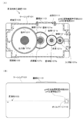
- FIG. 1 is a schematic explanatory view of a lubricant encapsulation device according to the first embodiment.
- FIG. 1A shows a cross-sectional view seen from the side surface of the lubricant encapsulating device
- FIG. 1B shows an external view seen from the side surface of the lubricant encapsulating device.
- the lubricant encapsulating device 100 includes an internal mechanism having a sliding portion, a casing 101 in which the lubricant 103 is encapsulated, and a pH responsive substance arranging means for arranging the pH responsive substance 20. It has 200 and.
- An example of the lubricant filling device 100 is a parallel shaft type speed reducer.
- the casing 101 is provided with a plurality of gears 121a to 121f (hereinafter collectively referred to as "gears 121”) as an internal mechanism having a sliding portion, and a space in which the lubricant 103 is stored.
- a storage chamber 105 is provided.
- a plurality of shafts 107a to 107d (hereinafter collectively referred to as “shafts 107") are provided in the casing 101 substantially in parallel.
- the shaft 107 includes an input shaft 107a, a first gear shaft 107b, a second gear shaft 107c, and an output shaft 107d.
- Each shaft 107 is rotatably supported by a casing 101 via a bearing (not shown).
- the casing 101 is provided with an inspection port 111 for inspecting the inside.
- the inspection port 111 is opened and closed by the lid member 113.
- the lid member 113 is detachably attached to the casing 101 with screws or the like.
- the casing 101 is provided with an oil gauge 115 for confirming the liquid level of the lubricant 103 from the outside.
- the gear 121 is housed in the casing 101.
- the plurality of gears 121 include an input gear 121a, a first large-diameter gear 121b, a first small-diameter gear 121c, a second large-diameter gear 121d, a second small-diameter gear 121e, and an output gear 121f.
- the input gear 121a is fixed to the input shaft 107a to form an input gear set.
- the first large-diameter gear 121b and the first small-diameter gear 121c are fixed to the first gear shaft 107b
- the second large-diameter gear 121d and the second small-diameter gear 121e are fixed to the second gear shaft 107c.
- the output gear 121f is fixed to the output shaft 107d to form an output stage gear set.
- Each gear 121 is partially immersed in the lubricant 103.
- the lubricant filling device 100 in the present embodiment includes at least an input stage gear set (combination of the input gear 121a and the input shaft 107a) and an output stage gear set (combination of the output gear 121f and the input shaft 107d).
- a plurality of gear sets (combination of gears 121b to 121e and gear shafts 107b and 107c) are provided between the input stage gear set and the output stage gear set. It is not limited.
- the input shaft 107a is connected to a motor (not shown).
- a motor not shown
- the rotation is decelerated by the plurality of gears 121 and transmitted to the output shaft 107d.
- the rotation of the gear 121 supplies the lubricant 103 to the gear 121, the shaft 107, and the bearing.
- the lubricant 103 is affected by temperature and moisture depending on the usage environment and usage conditions, and is oxidized or hydrolyzed.
- an organic acid may be generated by the oxidation of the grease, and the pH of the lubricant 103 may be lowered.
- sulfur-based additive is contained as an additive of the lubricant 103, sulfuric acid is generated due to the influence of temperature and moisture, and the pH of the lubricant 103 may be lowered.
- the thickener (particularly metal soap) contained as a component of the lubricant 103 may be hydrolyzed to form hydroxide, and the pH of the lubricant 103 may rise.
- the pH of the lubricant 103 is lowered or raised, there is a problem that sludge, which is an insoluble matter, is generated, and problems such as corrosion of the apparatus occur. Therefore, by monitoring the pH fluctuation of the lubricant 103 in real time, it is possible to appropriately respond to the occurrence of a problem due to the pH fluctuation of the lubricant 103.
- the pH responsive substance arranging means 200 in the present embodiment is for arranging the above-mentioned pH responsive substance 20 in the casing 101 and bringing the pH responsive substance 20 into contact with the lubricant 103. As a result, a situation is formed in which the molecular structure of the pH-responsive substance 20 changes according to the pH change of the lubricant 103, and the pH change of the lubricant 103 can be monitored in real time.
- the pH-responsive substance arranging means 200 may be any as long as it can be arranged in the casing 101 so that the pH-responsive substance 20 is in contact with the lubricant 103, and the specific configuration is not particularly limited. Further, the form of the pH responsive substance 20 arranged by the pH responsive substance arranging means 200 is not particularly limited. For example, the pH-responsive substance 20 may be in any state such as a solid (molded product, powder, etc.) or a liquid. Further, the pH responsive substance 20 may be directly arranged by the pH responsive substance arranging means 200, or the pH responsive substance 20 may be supported on a carrier or the like.
- the carrier on which the pH-responsive substance 20 is supported is not particularly limited. Examples of the carrier include sheets, granules, molded products and the like made of paper, resin, porous material and the like.
- FIG. 2 is a cross-sectional view showing an example of a pH-responsive substance arranging means in the lubricant encapsulating device of the first embodiment.
- a section A in which the pH responsive substance 20 can be arranged may be provided on the wall surface side in the casing 101.
- the compartment A may be any as long as it can arrange the pH-responsive substance 20 and suppress the outflow of the pH-responsive substance 20, and the means for forming the compartment A is not particularly limited.
- a box body 201 containing the pH-responsive substance 20 and having the inlet 201a and the outlet 201b of the lubricant 103 may be provided.
- the lubricant 103 and the pH-responsive substance 20 can be brought into contact with each other.
- the introduction port 201a and the outlet port 201b in the box body 201 may be provided as separate bodies as shown in FIG. 2, or the introduction port and the outlet port may be integrated.
- the pH-responsive substance 20 is preferably in the form of being supported on a carrier (sheet or the like) or in the form of a molded product. As a result, the pH-responsive substance 20 can be easily contained in the box 201, and it is also easy to prevent the pH-responsive substance 20 from flowing out of the box 201.
- the position where the pH responsive substance 20 is arranged is not particularly limited by the pH responsive substance arranging means 200.
- the pH-responsive substance 20 may be placed at a place where it is easy to confirm the state of the pH-responsive substance 20 related to the change in the molecular structure.
- the pH response substance 20 is arranged on the input stage gear set (combination of the input gear 121a and the input shaft 107a) as shown in FIG. Can be mentioned.
- the pH responsive substance 20 is arranged on the side where the rotation speed of the gear is high in the gear device, the pH fluctuation of the lubricant 103 can be monitored at a place where the stirring efficiency of the lubricant 103 is high.
- the pH fluctuation of the lubricant 103 can be monitored at the location where the lubricant 103 is uniform, and the accuracy in monitoring can be improved.
- the pH-responsive substance 20 arranged in the casing 101 by the pH-responsive substance arranging means 200 has a molecular structure that changes according to the pH of the lubricant 103 in contact with the casing 101. Therefore, it is possible to monitor the pH change of the lubricant 103 by confirming the state of the pH-responsive substance 20 related to the change in the molecular structure.
- the lubricant encapsulating device 100 in the present embodiment is provided with a confirmation means 210 for confirming the state of the pH-responsive substance 20 related to the molecular structure change, and obtains information on the pH fluctuation of the lubricant 103. This makes it possible to easily monitor the pH fluctuation of the lubricant 103 during the operation of the lubricant encapsulation device 100.
- a confirmation window 211 may be provided in the casing 101.
- the confirmation window 211 and the pH responsive substance arranging means 200 are provided close to each other.
- the lubricant encapsulation device is in operation. It becomes easy to monitor the pH fluctuation of the lubricant 103 in the above.
- the confirmation window 211 is provided as the confirmation means 210, the operator can visually confirm the pH fluctuation. As a result, the pH fluctuation of the lubricant 103 can be easily monitored, and the pH fluctuation of the lubricant 103 can be quickly dealt with.
- the pH responsive substance 20 shown in the formulas 1 to 3 is used.
- the color of the pH-responsive substance 20 changes according to the above, it is possible to make a judgment based on the color change in the visible light region.
- there is a change in the physical properties of the pH-responsive substance 20 such as a change in the solubility of the pH-responsive substance 20 in a solvent and a change in the refractive index due to a change in the pro-solvent / sparse solvent depending on the pH. If it does occur, visual judgment may be made in the form of transparency / opacity.
- the buoyancy of the pH-responsive substance 20 changes, and a visual judgment can be made in the form of the degree of ups and downs from the reference plane.
- the confirmation window 211 in this embodiment is also used as the oil gauge 115 provided in the lubricant filling device 100. That is, it is preferable that the pH-responsive substance arranging means 200 and the oil gauge 115 are provided close to each other. This simplifies the structure for monitoring the pH fluctuation of the lubricant 103, and makes it possible to monitor the pH fluctuation of the lubricant 103 at low cost.
- the confirmation means 210 a detection device for confirming the state of the pH-responsive substance 20 related to the change in the molecular structure can be mentioned. More specifically, it is possible to provide a device such as a camera capable of acquiring and analyzing image data, a device capable of acquiring and analyzing spectral data, and the like. It should be noted that the determination of the pH fluctuation of the lubricant 103 may be performed in the same manner as the above-mentioned visual determination.
- the installation location of the detection device may be inside or outside the lubricant encapsulation device 100.
- the detection device when the detection device is provided in the lubricant encapsulation device 100, it is possible to confirm the state of the pH-responsive substance 20 related to the change in the molecular structure without providing the confirmation window 211. Further, when the detection device is provided outside the lubricant encapsulation device 100, it is possible to confirm the state of the pH-responsive substance 20 related to the change in the molecular structure through the confirmation window 211.
- the detection device is used as the confirmation means 210, it becomes easy to automate the confirmation and judgment of the state of the pH-responsive substance 20 related to the change in the molecular structure, and it is possible to continuously monitor the pH change of the lubricant 103. Become.
- the lubricant encapsulation device of the present embodiment by arranging the pH responsive substance in contact with the encapsulated lubricant, the molecular structure of the pH responsive substance generated according to the pH of the lubricant. Based on the change, it becomes possible to grasp the pH fluctuation of the lubricant. That is, it is possible to grasp the pH fluctuation of the lubricant in the lubricant encapsulation device without collecting the lubricant from the lubricant encapsulation device. This makes it possible to monitor the pH fluctuation of the lubricant during the operation of the lubricant filling device.
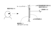
- FIG. 3 is a schematic explanatory view of a pH-responsive substance arranging means in the lubricant encapsulating device according to the second embodiment of the present invention. Note that FIG. 3 is a cross-sectional view showing another embodiment of the pH-responsive substance arranging means 200 in the lubricant encapsulating device 100 of the first embodiment. Further, the description of the same configuration as that of the first embodiment will be omitted.
- a confirmation window 211 is provided as the confirmation means 210, and the pH response substance 20 is used as the pH response substance arrangement means 200.
- the confirmation window 211 (oil gauge 115).
- a holding means 203 for directly holding the window is provided.
- the holding means 203 for holding the pH-responsive substance 20 in the confirmation window 211 is not particularly limited.
- a carrier carrying the pH-responsive substance 20 may be attached to the confirmation window 211, or the pH-responsive substance 20 may be directly applied to the surface of the confirmation window 211.
- the peeling of the pH-responsive substance 20 is suppressed by using a chemical such as an adhesive or by performing a surface treatment on the confirmation window 211. May be good.
- the lubricant encapsulating device in the present embodiment makes it easy to confirm the state of the molecular structure change of the pH-responsive substance that occurs depending on the pH of the lubricant through the confirmation window, and the lubricant during the operation of the lubricant encapsulating device. It becomes possible to monitor the pH fluctuation of the above more easily.
- FIG. 4 is a schematic explanatory view of a pH-responsive substance arranging means in the lubricant encapsulating device according to the third embodiment of the present invention. Note that FIG. 4 is a cross-sectional view showing another embodiment of the pH-responsive substance arranging means 200 in the lubricant encapsulating device 100 of the first embodiment. Further, the description of the same configuration as that of the first embodiment will be omitted.
- the lubricant 103 in the lubricant encapsulating device 100 may contain wear debris generated by driving an internal mechanism (gear 121, etc.). In order to improve the accuracy and accuracy of monitoring the pH fluctuation of the lubricant 103, it is preferable to provide a foreign matter removing means for removing foreign matter such as wear debris.
- a section A may be formed by a filter 205 and a filter fixing frame (not shown).
- the filter 205 functions as a foreign matter removing means for removing foreign matter from the lubricant 103 before coming into contact with the pH-responsive substance 20. Therefore, it is possible to introduce only the lubricant 103 containing no foreign matter (mainly wear debris) into the compartment A and bring it into contact with the pH responsive substance 20.
- the filter 205 used as the foreign matter removing means may be any as long as it can trap foreign matter such as abrasion powder.
- a nylon net filter, a polypropylene filter, a glass fiber filter, or the like, which is called a depth filter may be used.
- the lubricant encapsulating device in the present embodiment suppresses the reaction between the pH-responsive substance and the lubricant by foreign matter contained in the lubricant, and confirms the state of structural changes in the pH-responsive substance. It is possible to remove the obstructive factor. This makes it possible to improve the accuracy in monitoring the pH fluctuation of the lubricant during the operation of the lubricant filling device.
- the above-described embodiment shows an example of a lubricant encapsulating device, a lubricant, and an additive.
- the lubricant encapsulating device, the lubricant and the additive according to the present invention are not limited to the above-described embodiment, and the lubricant encapsulating device according to the above-described embodiment is not changed as long as the gist described in the claim is not changed. Lubricants and additives may be modified.
- the location where the pH responsive substance is arranged by the pH responsive substance arranging means may be a position where the pH responsive substance can be exchanged from the inspection port of the casing.
- the pH responsive substance arranging means in the second embodiment and the third embodiment may be combined. This makes it easy to confirm how the molecular structure of the pH-responsive substance changes in response to changes in pH while reducing the volume of the compartment formed as the means for arranging the pH-responsive substance.
- the lubricant encapsulation device of the present invention can be used as a mechanical device in which a lubricant is encapsulated and various sliding portions are provided.
- the lubricant encapsulation device of the present invention is suitably used as, for example, a gear device, a speed reducer, and the like.
- it can be used as a lubricant encapsulating device that can monitor pH fluctuations of a lubricant during operation of a mechanical device and can appropriately detect deterioration of the lubricant.
- the lubricant and the additive of the present invention are used as an additive to be added to the lubricant and the lubricant used in various mechanical devices in order to suppress friction and wear of device parts (particularly sliding parts). ..
- it is suitably used as a lubricant and an additive capable of easily monitoring the pH fluctuation of the lubricant and appropriately detecting the deterioration of the lubricant.
Landscapes
- Chemical & Material Sciences (AREA)
- Engineering & Computer Science (AREA)
- General Engineering & Computer Science (AREA)
- Chemical Kinetics & Catalysis (AREA)
- General Chemical & Material Sciences (AREA)
- Oil, Petroleum & Natural Gas (AREA)
- Organic Chemistry (AREA)
- Mechanical Engineering (AREA)
- Lubricants (AREA)
- Investigating Or Analyzing Non-Biological Materials By The Use Of Chemical Means (AREA)
- General Details Of Gearings (AREA)
Abstract
本発明の課題は、潤滑剤封入装置の運転中における潤滑剤のpH変動を監視することができる潤滑剤封入装置を提供することである。また、潤滑剤のpH変動を速やかに把握することが可能な潤滑剤及び添加剤を提供することである。 上記課題を解決するために、封入された潤滑剤と接する箇所に、潤滑剤のpHによって分子構造が変化するpH応答物質が配置されている潤滑剤封入装置を提供し、また、pH応答物質を含む潤滑剤及び潤滑剤に添加する添加剤を提供する。 本発明によれば、潤滑剤と接するようにpH応答物質を配置することにより、潤滑剤のpHに応じて生じるpH応答物質の分子構造変化を基に、潤滑剤封入装置の運転中における潤滑剤のpH変動を監視することが可能となる。また、pH応答物質を含む潤滑剤及び潤滑剤に添加する添加剤により、潤滑剤のpH変動を速やかに把握することができる。
Description
本発明は、潤滑剤封入装置、潤滑剤及び添加剤に関するものである。
歯車装置などの機械には、潤滑剤が収容されており、摺動部に生じる摩擦を軽減している(以下、潤滑剤が収容された機械全般を「潤滑剤封入装置」と呼ぶ)。潤滑剤は、使用環境や使用条件により徐々に劣化することが知られており、潤滑剤封入装置には、潤滑剤の劣化を抑制する手段を設けることが行われている。
例えば、特許文献1には、潤滑剤封入装置である直交減速装置において、潤滑剤の温度上昇に起因した劣化を抑制するために、潤滑剤を収容するための空間を大きくする手段や、冷却風により冷却することにより潤滑剤の温度の上昇を抑制する手段などが開示されている。
特許文献1に記載されるように、潤滑剤封入装置内の潤滑剤の劣化を抑制する手段が検討されている一方で、潤滑剤封入装置内の潤滑剤がどの程度劣化しているかについて把握することも必要となる。
そこで、本発明の課題は、潤滑剤封入装置内の潤滑剤の劣化を把握できる潤滑剤封入装置を提供することである。また、潤滑剤の劣化を把握することが可能な潤滑剤及び添加剤を提供することである。
上記課題を解決するための本発明の潤滑剤封入装置は、潤滑剤が封入された潤滑剤封入装置であって、封入された潤滑剤と接する箇所に、潤滑剤のpHによって分子構造が変化するpH応答物質が配置されていることを特徴とする。
本発明の潤滑剤封入装置によれば、封入された潤滑剤と接触するようにpH応答物質を配置することにより、潤滑剤のpHに応じて生じるpH応答物質の分子構造変化を基に、潤滑剤のpH変動を把握することが可能となる。つまり、潤滑剤封入装置から潤滑剤を採取することなく、潤滑剤封入装置内における潤滑剤のpH変動を把握することが可能となる。これにより、潤滑剤封入装置の運転中における潤滑剤のpH変動を監視することが可能となる。
本発明の潤滑剤封入装置によれば、封入された潤滑剤と接触するようにpH応答物質を配置することにより、潤滑剤のpHに応じて生じるpH応答物質の分子構造変化を基に、潤滑剤のpH変動を把握することが可能となる。つまり、潤滑剤封入装置から潤滑剤を採取することなく、潤滑剤封入装置内における潤滑剤のpH変動を把握することが可能となる。これにより、潤滑剤封入装置の運転中における潤滑剤のpH変動を監視することが可能となる。
また、本発明の潤滑剤封入装置の一実施態様としては、pH応答物質は、潤滑剤のpHに応じて色が変化するものであるという特徴を有する。
この特徴によれば、潤滑剤のpH変動を、色の変化として把握することが可能となる。これにより、簡便な手段で潤滑剤のpH変動を監視することが可能となる。
この特徴によれば、潤滑剤のpH変動を、色の変化として把握することが可能となる。これにより、簡便な手段で潤滑剤のpH変動を監視することが可能となる。
また、本発明の潤滑剤封入装置の一実施態様としては、潤滑剤封入装置は、ケーシングと、ケーシングの内部を確認可能な確認窓とを備え、pH応答物質は、確認窓から確認可能な箇所に配置されるという特徴を有する。
この特徴によれば、pH応答物質の分子構造変化に係る様子を、潤滑剤封入装置の外部から確認し、潤滑剤のpH変動を把握することが可能となる。これにより、潤滑剤封入装置の運転中における潤滑剤のpH変動の監視を容易に行うことが可能となる。
この特徴によれば、pH応答物質の分子構造変化に係る様子を、潤滑剤封入装置の外部から確認し、潤滑剤のpH変動を把握することが可能となる。これにより、潤滑剤封入装置の運転中における潤滑剤のpH変動の監視を容易に行うことが可能となる。
また、本発明の潤滑剤封入装置の一実施態様としては、確認窓は、封入された潤滑剤の液位を確認するオイルゲージであるという特徴を有する。
この特徴によれば、オイルゲージに確認窓の機能を兼用させることで、潤滑剤のpH変動を監視するための構造を簡略化し、低コストで潤滑剤のpH変動を監視することが可能となる。
この特徴によれば、オイルゲージに確認窓の機能を兼用させることで、潤滑剤のpH変動を監視するための構造を簡略化し、低コストで潤滑剤のpH変動を監視することが可能となる。
また、本発明の潤滑剤封入装置の一実施態様としては、pH応答物質は、確認窓に保持されているという特徴を有する。
この特徴によれば、潤滑剤のpHに応じて生じるpH応答物質の分子構造変化に係る様子を、確認窓を通して確認することが容易となり、潤滑剤封入装置の運転中における潤滑剤のpH変動の監視をより一層容易に行うことが可能となる。
この特徴によれば、潤滑剤のpHに応じて生じるpH応答物質の分子構造変化に係る様子を、確認窓を通して確認することが容易となり、潤滑剤封入装置の運転中における潤滑剤のpH変動の監視をより一層容易に行うことが可能となる。
また、本発明の潤滑剤封入装置の一実施態様としては、pH応答物質に接する前の潤滑剤から異物を除去する異物除去手段を備えるという特徴を有する。
この特徴によれば、潤滑剤に含まれる異物により、pH応答物質と潤滑剤の反応が阻害されることを抑制するとともに、pH応答物質の構造変化に係る様子を確認する際の阻害要因となるものを除去することが可能となる。これにより、潤滑剤封入装置の運転中における潤滑剤のpH変動の監視における確度を高めることが可能となる。
この特徴によれば、潤滑剤に含まれる異物により、pH応答物質と潤滑剤の反応が阻害されることを抑制するとともに、pH応答物質の構造変化に係る様子を確認する際の阻害要因となるものを除去することが可能となる。これにより、潤滑剤封入装置の運転中における潤滑剤のpH変動の監視における確度を高めることが可能となる。
また、本発明の潤滑剤封入装置の一実施態様としては、潤滑剤封入装置は、入力段歯車セットと出力段歯車セットとを有する歯車装置であり、pH応答物質は、出力段歯車セットよりも入力段歯車セットに近い箇所に配置されるという特徴を有する。
この特徴によれば、歯車装置において、歯車の回転速度が速い側(入力段歯車セット側)にpH応答物質を配置することで、潤滑剤の撹拌効率の高い箇所において潤滑剤のpH変動を監視することができる。これにより、潤滑剤が一様となっている箇所において、潤滑剤のpH変動を監視することができ、監視における確度を高めることが可能となる。
この特徴によれば、歯車装置において、歯車の回転速度が速い側(入力段歯車セット側)にpH応答物質を配置することで、潤滑剤の撹拌効率の高い箇所において潤滑剤のpH変動を監視することができる。これにより、潤滑剤が一様となっている箇所において、潤滑剤のpH変動を監視することができ、監視における確度を高めることが可能となる。
また、上記課題を解決するための本発明の潤滑剤は、潤滑油、及び、pHによって分子構造が変化するpH応答物質を含むことを特徴とする。
この潤滑剤によれば、摺動部を有する種々の装置において、摺動部の摩擦、摩耗を抑制しつつ、さらには、潤滑剤のpH変動を速やかに把握することができる。
この潤滑剤によれば、摺動部を有する種々の装置において、摺動部の摩擦、摩耗を抑制しつつ、さらには、潤滑剤のpH変動を速やかに把握することができる。
また、上記課題を解決するための本発明の添加剤は、潤滑剤に添加する添加剤であって、添加剤は、pHによって分子構造が変化するpH応答物質を含むことを特徴とする。
この添加剤によれば、潤滑剤に添加することにより、潤滑剤のpH変動を速やかに把握することが可能な潤滑剤を得ることができる。
この添加剤によれば、潤滑剤に添加することにより、潤滑剤のpH変動を速やかに把握することが可能な潤滑剤を得ることができる。
本発明によれば、潤滑剤封入装置の運転中における潤滑剤のpH変動を監視することができる潤滑剤封入装置を提供することができる。また、潤滑剤のpH変動を速やかに把握することが可能な潤滑剤及び添加剤を提供することができる。
潤滑剤は、酸化劣化や水分の混入によりpHの変動が起こることがある。したがって、潤滑剤のpH変動を把握することは重要である。潤滑剤封入装置内の潤滑剤のpH変動を把握する手段としては、潤滑剤封入装置の運転を停止した状態で潤滑剤を採取し、採取した潤滑剤のpHについて各種分析装置を用いて分析することが行われている。
しかしながら、潤滑剤封入装置の運転を頻繁に停止して潤滑剤のpHを確認することは現実的ではなく、かつ分析にも一定の時間を要するため、潤滑剤のpH変動をリアルタイムで把握することは困難であった。
本発明者は、上記の課題について鋭意検討した結果、潤滑剤に対し、潤滑剤のpHによって分子構造が変化する物質を接触させることで、潤滑剤のpH変動をリアルタイムで把握することが可能となることを見出して、本発明を完成した。
[潤滑剤封入装置]
本発明の潤滑剤封入装置は、歯車、カム、軸受など各種摺動部を備える機械装置において、摺動部の損傷、摩耗、摩擦等を防止するために潤滑剤が封入され、かつpH応答物質を配置することができる装置であればよく、それ以外の構造については特に限定されない。
しかしながら、潤滑剤封入装置の運転を頻繁に停止して潤滑剤のpHを確認することは現実的ではなく、かつ分析にも一定の時間を要するため、潤滑剤のpH変動をリアルタイムで把握することは困難であった。
本発明者は、上記の課題について鋭意検討した結果、潤滑剤に対し、潤滑剤のpHによって分子構造が変化する物質を接触させることで、潤滑剤のpH変動をリアルタイムで把握することが可能となることを見出して、本発明を完成した。
[潤滑剤封入装置]
本発明の潤滑剤封入装置は、歯車、カム、軸受など各種摺動部を備える機械装置において、摺動部の損傷、摩耗、摩擦等を防止するために潤滑剤が封入され、かつpH応答物質を配置することができる装置であればよく、それ以外の構造については特に限定されない。
本発明の潤滑剤封入装置としては、例えば、歯車装置として知られるものが挙げられる。
歯車装置は、歯車等で動力の回転速度を増減して出力する機械装置である。出力としては、歯数比やプーリー比などの減速比に比例したトルクを得ることができる。歯車装置のうち、減速装置は、主に原動機の出力軸に用いられるが、自動車の最終減速機のように、変速機の後段に用いる場合もある。また、産業用、鉄道車両用などでは、モータと組み合わせている場合が多い。その他、船舶のスクリュープロペラや航空機のプロペラ駆動にも利用されているものが挙げられる。
歯車装置は、歯車等で動力の回転速度を増減して出力する機械装置である。出力としては、歯数比やプーリー比などの減速比に比例したトルクを得ることができる。歯車装置のうち、減速装置は、主に原動機の出力軸に用いられるが、自動車の最終減速機のように、変速機の後段に用いる場合もある。また、産業用、鉄道車両用などでは、モータと組み合わせている場合が多い。その他、船舶のスクリュープロペラや航空機のプロペラ駆動にも利用されているものが挙げられる。
本発明の潤滑剤封入装置(歯車装置)の具体的な例としては、例えば、平行軸歯車減速機やヘリカル減速機などの平行軸型減速装置、ウォーム減速機やベベルギア減速機やハイポイド減速機などの直交軸型減速装置、遊星歯車減速機や波動歯車減速機や偏心揺動型減速機などの同芯軸型減速装置、ローラ減速機などのトラクションドライブ型減速装置などが挙げられる。
なお、以下の実施態様においては、潤滑剤封入装置として歯車装置(平行軸型減速装置)の構造について主に説明するが、これに限定されるものではない。
なお、以下の実施態様においては、潤滑剤封入装置として歯車装置(平行軸型減速装置)の構造について主に説明するが、これに限定されるものではない。
[潤滑剤]
本発明の潤滑剤は、潤滑剤のpH変動を速やかに把握することができる潤滑剤であって、潤滑油、及び、潤滑剤のpHによって分子構造が変化するpH応答物質を含むものである。つまり、本明細書においては、装置内の摺動部における摩擦や摩耗の抑制、あるいは発熱の抑制のための潤滑成分を有するものを「潤滑油」と表現し、当該潤滑油にpH応答物質を添加剤として添加したものを「潤滑剤」と表現している。
本発明の潤滑剤は、潤滑剤のpH変動を速やかに把握することができる潤滑剤であって、潤滑油、及び、潤滑剤のpHによって分子構造が変化するpH応答物質を含むものである。つまり、本明細書においては、装置内の摺動部における摩擦や摩耗の抑制、あるいは発熱の抑制のための潤滑成分を有するものを「潤滑油」と表現し、当該潤滑油にpH応答物質を添加剤として添加したものを「潤滑剤」と表現している。
この潤滑剤によれば、摺動部を有する種々の機械装置において、摺動部の摩擦や摩耗を抑制しつつ、さらには、潤滑剤のpH変動を速やかに把握し、潤滑剤の劣化に係る監視を適切に行うことが可能となる。つまり、本発明の潤滑剤が適用できる機械装置は、潤滑剤封入装置に限られるものではなく、潤滑剤を封入する空間を設けることなく、潤滑剤と接触させる摺動部を有する各種機械装置にも適用可能である。例えば、ロッドを有するシリンダ装置、ボールネジ装置などにも適用可能である。
(潤滑油)
潤滑油は、例えば歯車装置の歯車や軸受など、機械装置の摺動部を効率よく潤滑するための潤滑成分として機能する油である。潤滑油としては、公知のオイルやグリースを採用可能であるが、これに限定されるものではない。
潤滑油は、例えば、鉱物油、合成油、植物油、動物油に大別される。
鉱物油は、石油の精製により得られる潤滑油であり、例えば、パラフィン系鉱物油、ナフテン系鉱物油などが挙げられる。
合成油は、化学合成により得られた潤滑油であり、例えば、ポリアルファオレフィン、アルファオレフィンオレゴマー、ポリブデン、アルキルベンゼン、シクロアルカン類などの炭化水素系合成油、モノエステル、ジエステル、ポリオールエステル、リン酸エステル、ケイ酸エステルなどのエステル系合成油、ポリグリコール、フェニルエーテルなどのエーテル系合成油、ハロカーボンなどのフッ素系合成油などが挙げられる。
植物油は、植物由来の潤滑油であり、例えば、パーム油、菜種油、ヒマシ油、大豆油、亜麻仁油、ヒマワリ油、オリーブ油、ヤシ油、パーム核油、コメ油、トウモロコシ油、又はこれらの分別油、硬化油、エステル交換油などの植物油脂、ポリオキシアルキレン化油脂、塩素化油、硫化油、重合油、ワックス、脂肪酸、脂肪酸誘導体、セッケン、エステル化油、アミド化油、ポリオキシアルキレン付加体などが挙げられる。
動物油は、動物由来の潤滑油であり、例えば、牛脂、豚脂、羊脂、鯨油、イワシ油、ニシン油、乳脂などが挙げられる。
潤滑油は、例えば歯車装置の歯車や軸受など、機械装置の摺動部を効率よく潤滑するための潤滑成分として機能する油である。潤滑油としては、公知のオイルやグリースを採用可能であるが、これに限定されるものではない。
潤滑油は、例えば、鉱物油、合成油、植物油、動物油に大別される。
鉱物油は、石油の精製により得られる潤滑油であり、例えば、パラフィン系鉱物油、ナフテン系鉱物油などが挙げられる。
合成油は、化学合成により得られた潤滑油であり、例えば、ポリアルファオレフィン、アルファオレフィンオレゴマー、ポリブデン、アルキルベンゼン、シクロアルカン類などの炭化水素系合成油、モノエステル、ジエステル、ポリオールエステル、リン酸エステル、ケイ酸エステルなどのエステル系合成油、ポリグリコール、フェニルエーテルなどのエーテル系合成油、ハロカーボンなどのフッ素系合成油などが挙げられる。
植物油は、植物由来の潤滑油であり、例えば、パーム油、菜種油、ヒマシ油、大豆油、亜麻仁油、ヒマワリ油、オリーブ油、ヤシ油、パーム核油、コメ油、トウモロコシ油、又はこれらの分別油、硬化油、エステル交換油などの植物油脂、ポリオキシアルキレン化油脂、塩素化油、硫化油、重合油、ワックス、脂肪酸、脂肪酸誘導体、セッケン、エステル化油、アミド化油、ポリオキシアルキレン付加体などが挙げられる。
動物油は、動物由来の潤滑油であり、例えば、牛脂、豚脂、羊脂、鯨油、イワシ油、ニシン油、乳脂などが挙げられる。
(pH応答物質)
pH応答物質は、pHによって分子構造が変化するものであればよく、特に限定されない。ここで、「pHによって分子構造が変化する」とは、pHの変化、すなわち物質周辺のプロトン濃度の変化によって、物質の分子構造における結合状態が変化すること(結合の形成・切断のほか、一重結合から二重結合へ又は二重結合から一重結合への変化等)や、物質の分子構造の一部がプロトン化あるいは脱プロトン化することなどが挙げられる。
pH応答物質は、pHによって分子構造が変化するものであればよく、特に限定されない。ここで、「pHによって分子構造が変化する」とは、pHの変化、すなわち物質周辺のプロトン濃度の変化によって、物質の分子構造における結合状態が変化すること(結合の形成・切断のほか、一重結合から二重結合へ又は二重結合から一重結合への変化等)や、物質の分子構造の一部がプロトン化あるいは脱プロトン化することなどが挙げられる。
pH応答物質としては、pHによる分子構造の変化に係る様子を簡易な手段で確認することができるものが好ましい。また、pHによる分子構造の変化が可逆的に生じるものが好ましい。これにより、潤滑剤のpH変動を簡便に検知することが可能となるとともに、pH応答物質の交換や追加を行うことなく、潤滑剤のpH変動を繰り返し確認することが可能となり、潤滑剤のpH変動を監視することが容易となる。
なお、本発明においては、潤滑剤のpH変動が確認された段階で、封入された潤滑剤の交換等、潤滑剤封入装置のメンテナンス作業を実施することが想定される。したがって、pH応答物資としては、pHによる分子構造の変化が不可逆的なものであっても、潤滑剤のpH変動を検知することができるものであれば用いることができる。そして、潤滑剤封入装置のメンテナンスに併せてpH応答物質の交換あるいは追加を行うことで、潤滑剤のpH変動の監視を行うことが可能となる。
なお、本発明においては、潤滑剤のpH変動が確認された段階で、封入された潤滑剤の交換等、潤滑剤封入装置のメンテナンス作業を実施することが想定される。したがって、pH応答物資としては、pHによる分子構造の変化が不可逆的なものであっても、潤滑剤のpH変動を検知することができるものであれば用いることができる。そして、潤滑剤封入装置のメンテナンスに併せてpH応答物質の交換あるいは追加を行うことで、潤滑剤のpH変動の監視を行うことが可能となる。
本発明のpH応答物質の例としては、pHにより色が変化するものや、pHにより各種物性が変化するものなどが挙げられる。
pHにより色が変化するpH応答物質の一例として、以下の化学構造式(式1)に記載のキノンジイミンが挙げられる。なお、式1は、pHに応じたpH応答物質の構造変化について、式の左側から右側にかけてpHが高くなっていく順に示している。

また、pHにより色が変化するpH応答物質の他の例として、以下の化学構造式に記載のブロモチモールブルー(式2)やアントシアニン(式3)などが挙げられる。なお、式2及び式3においても、式1と同様に、pHに応じたpH応答物質の構造変化について、式の左側から右側にかけてpHが高くなっていく順に示している。

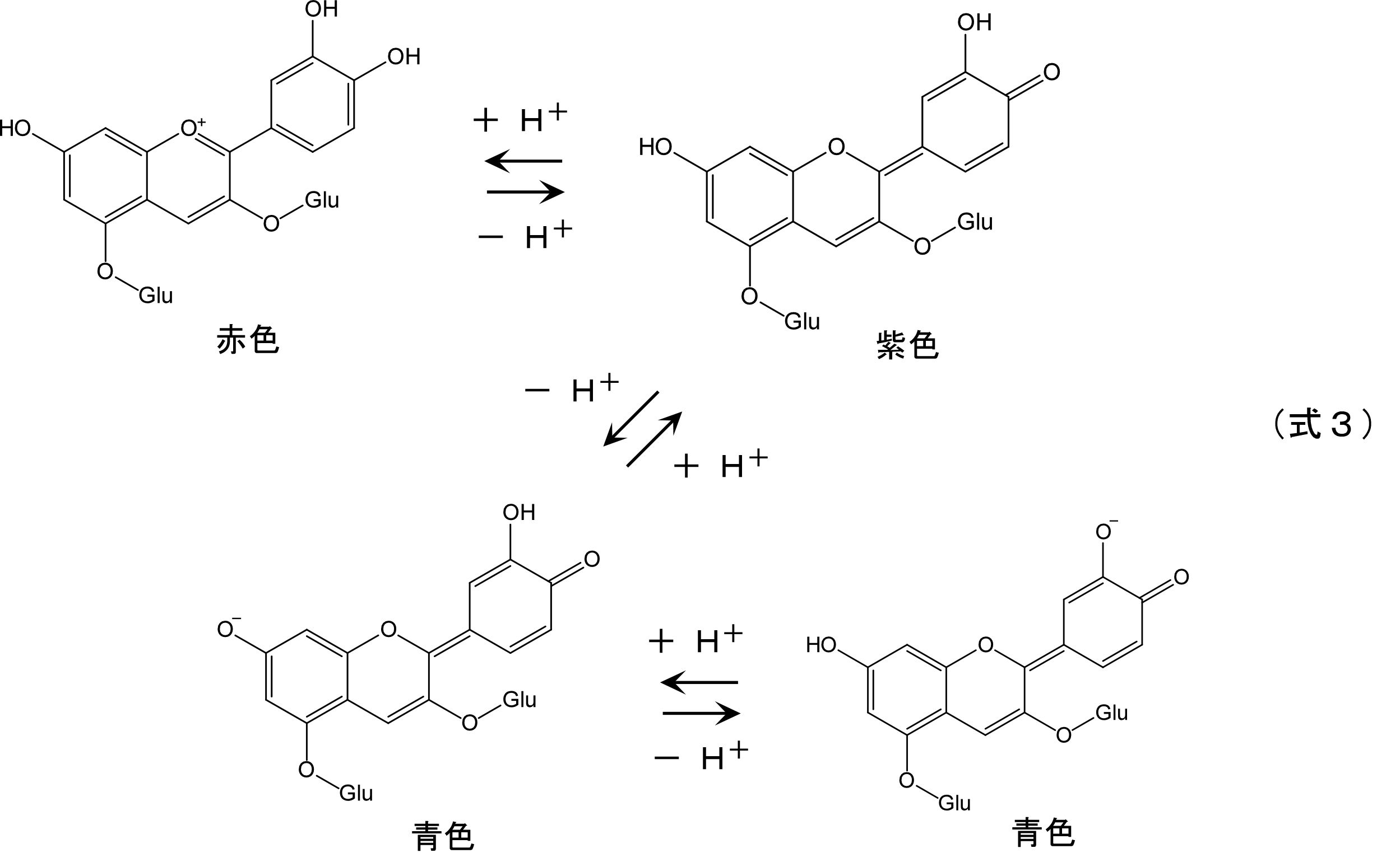
式1~式3に示したようなpH応答物質では、pHの変動により色の変化が生じる。したがって、この色の変化を検知することで、潤滑剤のpH変動を監視することが可能となる。
また、pHにより物性が変化するpH応答物質としては、カルボキシル基、リン酸基、スルホニル基、アミノ基などの解離性官能基を有するpH応答性ポリマーやpH応答性ゲル等が挙げられる。このようなpH応答性ポリマーやpH応答性ゲルは、pHの変動により、溶媒への溶解度や、親溶媒性/疎溶媒性、構造上の体積などの物性変化が生じることが知られている。したがって、この物性変化を検知することで、潤滑剤のpH変動を監視することが可能となる。
(その他成分)
本発明の潤滑剤は、その他の成分として、例えば、清浄分散剤、酸化防止剤、耐荷重添加剤、さび止め剤、腐食防止剤、粘度指数向上剤、流動点降下剤、消泡剤、乳化剤、抗乳化剤、カビ防止剤、増稠剤などが添加されているものでもよい。
本発明の潤滑剤は、その他の成分として、例えば、清浄分散剤、酸化防止剤、耐荷重添加剤、さび止め剤、腐食防止剤、粘度指数向上剤、流動点降下剤、消泡剤、乳化剤、抗乳化剤、カビ防止剤、増稠剤などが添加されているものでもよい。
以下、図面を参照しつつ本発明に係る潤滑剤封入装置の実施態様を詳細に説明する。また、この実施態様は、本発明に係る潤滑剤封入装置を説明するために例示したにすぎず、これに限定されるものではない。
〔第1の実施態様〕
図1は、第1の実施態様に係る潤滑剤封入装置の概略説明図である。なお、図1Aは、潤滑剤封入装置の側面から見た断面図を示し、図1Bは、潤滑剤封入装置の側面から見た外観図を示すものである。
図1に示すように、潤滑剤封入装置100は、摺動部を有する内部機構を備え、潤滑剤103が封入されているケーシング101と、pH応答物質20を配置するためのpH応答物質配置手段200とを備えている。
図1は、第1の実施態様に係る潤滑剤封入装置の概略説明図である。なお、図1Aは、潤滑剤封入装置の側面から見た断面図を示し、図1Bは、潤滑剤封入装置の側面から見た外観図を示すものである。
図1に示すように、潤滑剤封入装置100は、摺動部を有する内部機構を備え、潤滑剤103が封入されているケーシング101と、pH応答物質20を配置するためのpH応答物質配置手段200とを備えている。
潤滑剤封入装置100の一例としては、平行軸型減速装置が挙げられる。図1Aに示すように、ケーシング101内には、摺動部を有する内部機構として、複数の歯車121a~121f(以下、「歯車121」と総称する)を備え、潤滑剤103が貯留される空間として、貯留室105が設けられている。また、ケーシング101内には、複数の軸107a~107d(以下、「軸107」と総称する)が略平行に設けられる。軸107には、入力軸107a、第1歯車軸107b、第2歯車軸107c、出力軸107dが含まれる。各軸107は、ケーシング101に軸受(図示せず)を介して回転自在に支持される。
ケーシング101には、内部を点検するための点検口111が設けられる。点検口111は蓋部材113により開閉される。蓋部材113はケーシング101にねじ等で着脱可能に取り付けられる。また、ケーシング101には、潤滑剤103の液位を外部から確認するためのオイルゲージ115が設けられる。
歯車121は、ケーシング101内に収容される。複数の歯車121には、入力歯車121a、第1大径歯車121b、第1小径歯車121c、第2大径歯車121d、第2小径歯車121e及び出力歯車121fが含まれる。入力歯車121aは入力軸107aに固定され、入力段歯車セットを形成している。また、第1大径歯車121b及び第1小径歯車121cは第1歯車軸107bに固定され、第2大径歯車121d及び第2小径歯車121eは第2歯車軸107cに固定されている。さらに、出力歯車121fは出力軸107dに固定され、出力段歯車セットを形成している。各歯車121は、潤滑剤103に一部が漬かって設けられる。
なお、本実施態様における潤滑剤封入装置100は、少なくとも入力段歯車セット(入力歯車121aと入力軸107aの組み合わせ)及び出力段歯車セット(出力歯車121fと入力軸107dの組み合わせ)を備え、歯車装置として機能するものであればよく、図1のように、入力段歯車セットと出力段歯車セットの間に、複数の歯車セット(歯車121b~121eと歯車軸107b、107cの組み合わせ)を設けることに限定されるものではない。
なお、本実施態様における潤滑剤封入装置100は、少なくとも入力段歯車セット(入力歯車121aと入力軸107aの組み合わせ)及び出力段歯車セット(出力歯車121fと入力軸107dの組み合わせ)を備え、歯車装置として機能するものであればよく、図1のように、入力段歯車セットと出力段歯車セットの間に、複数の歯車セット(歯車121b~121eと歯車軸107b、107cの組み合わせ)を設けることに限定されるものではない。
入力軸107aは、モータ(図示せず)に連結される。モータの駆動により入力軸107aが回転すると、その回転が複数の歯車121により減速されて出力軸107dに伝達される。この歯車121の回転により、歯車121、軸107及び軸受に潤滑剤103が供給される。
ここで、潤滑剤103は、使用環境や使用条件によって、温度や水分の影響を受け、酸化や加水分解が生じることが知られている。例えば、潤滑剤103としてグリースを用いた場合、グリースの酸化により有機酸が生成し、潤滑剤103のpHが低下することがある。また、潤滑剤103の添加物として、硫黄系の添加剤を含む場合、温度や水分の影響により硫酸が生成し、潤滑剤103のpHが低下することもある。一方、潤滑剤103(特にグリース)の成分として含まれる増稠剤(特に金属石鹸)が加水分解して水酸化物が生成し、潤滑剤103のpHが上昇することもある。
潤滑剤103のpH低下又はpH上昇が生じることにより、不溶解分であるスラッジの生成や、装置の腐食などの不具合が発生するという問題がある。したがって、潤滑剤103のpH変動をリアルタイムで監視することで、潤滑剤103のpH変動による不具合発生に対し、適切に対応することが可能となる。
潤滑剤103のpH低下又はpH上昇が生じることにより、不溶解分であるスラッジの生成や、装置の腐食などの不具合が発生するという問題がある。したがって、潤滑剤103のpH変動をリアルタイムで監視することで、潤滑剤103のpH変動による不具合発生に対し、適切に対応することが可能となる。
本実施態様におけるpH応答物質配置手段200は、上述したpH応答物質20をケーシング101内に配置し、pH応答物質20と潤滑剤103とを接触させるためのものである。これにより、潤滑剤103のpH変動に応じてpH応答物質20の分子構造変化が生じる状況が形成され、潤滑剤103のpH変動をリアルタイムで監視することが可能となる。
pH応答物質配置手段200は、pH応答物質20が潤滑剤103と接するようにケーシング101内に配置することができるものであればよく、具体的な構成については特に限定されない。
また、pH応答物質配置手段200により配置されるpH応答物質20の形態は特に限定されない。例えば、pH応答物質20は、固体(成形体、粉体等)や液体など、いずれの状態であってもよい。さらに、pH応答物質配置手段200により、pH応答物質20を直接配置するものであってもよく、pH応答物質20を担体等に担持させたものを配置するものであってもよい。pH応答物質20を担持させる担体については特に限定されない。担体としては、例えば、紙、樹脂、多孔質体等からなるシート、粒体、成形体等が挙げられる。
また、pH応答物質配置手段200により配置されるpH応答物質20の形態は特に限定されない。例えば、pH応答物質20は、固体(成形体、粉体等)や液体など、いずれの状態であってもよい。さらに、pH応答物質配置手段200により、pH応答物質20を直接配置するものであってもよく、pH応答物質20を担体等に担持させたものを配置するものであってもよい。pH応答物質20を担持させる担体については特に限定されない。担体としては、例えば、紙、樹脂、多孔質体等からなるシート、粒体、成形体等が挙げられる。
図2は、第1の実施態様の潤滑剤封入装置におけるpH応答物質配置手段の一例を示す断面図である。
pH応答物質配置手段200として、図2に示すように、ケーシング101内の壁面側に、pH応答物質20を配置することができる区画Aを設けることが挙げられる。なお、区画AはpH応答物質20を配置するとともに、pH応答物質20の流出を抑制することができるものであればよく、区画Aを形成する手段は特に限定されない。
例えば、図2に示すように、pH応答物質20を収容し、潤滑剤103の導入口201a及び導出口201bを有する箱体201を設けることが挙げられる。この箱体201により形成された区画A内に、pH応答物質20を配置することで、潤滑剤103とpH応答物質20とを接触させることが可能となる。なお、箱体201における導入口201aと導出口201bは、図2のように別体として設けるものとしてもよく、導入口と導出口を一体とするものとしてもよい。
このとき、pH応答物質20は、図2に示すように、担体(シート等)に担持させた形態、あるいは成形体とすることが好ましい。これにより、箱体201内にpH応答物質20を容易に収容することができるとともに、箱体201内からpH応答物質20が流出することを抑制することも容易となる。
pH応答物質配置手段200として、図2に示すように、ケーシング101内の壁面側に、pH応答物質20を配置することができる区画Aを設けることが挙げられる。なお、区画AはpH応答物質20を配置するとともに、pH応答物質20の流出を抑制することができるものであればよく、区画Aを形成する手段は特に限定されない。
例えば、図2に示すように、pH応答物質20を収容し、潤滑剤103の導入口201a及び導出口201bを有する箱体201を設けることが挙げられる。この箱体201により形成された区画A内に、pH応答物質20を配置することで、潤滑剤103とpH応答物質20とを接触させることが可能となる。なお、箱体201における導入口201aと導出口201bは、図2のように別体として設けるものとしてもよく、導入口と導出口を一体とするものとしてもよい。
このとき、pH応答物質20は、図2に示すように、担体(シート等)に担持させた形態、あるいは成形体とすることが好ましい。これにより、箱体201内にpH応答物質20を容易に収容することができるとともに、箱体201内からpH応答物質20が流出することを抑制することも容易となる。
pH応答物質配置手段200により、pH応答物質20を配置する位置は特に限定されない。例えば、潤滑剤103とpH応答物質20が効果的に接触する箇所のほか、潤滑剤103の均質性が保たれている等、潤滑剤103がpH変動の監視に適した状態となっている箇所や、pH応答物質20の分子構造変化に係る様子の確認が容易となる箇所等に、pH応答物質20を配置することが挙げられる。
より具体的には、潤滑剤封入装置100が歯車装置である場合、図1に示すように、入力段歯車セット(入力歯車121aと入力軸107aの組み合わせ)側にpH応答物質20を配置することが挙げられる。ここで、歯車装置において歯車の回転速度が速い側にpH応答物質20を配置することになるため、潤滑剤103の撹拌効率の高い箇所において潤滑剤103のpH変動を監視することができる。これにより、潤滑剤103が一様となっている箇所において、潤滑剤103のpH変動を監視することができ、監視における確度を高めることが可能となる。
より具体的には、潤滑剤封入装置100が歯車装置である場合、図1に示すように、入力段歯車セット(入力歯車121aと入力軸107aの組み合わせ)側にpH応答物質20を配置することが挙げられる。ここで、歯車装置において歯車の回転速度が速い側にpH応答物質20を配置することになるため、潤滑剤103の撹拌効率の高い箇所において潤滑剤103のpH変動を監視することができる。これにより、潤滑剤103が一様となっている箇所において、潤滑剤103のpH変動を監視することができ、監視における確度を高めることが可能となる。
pH応答物質配置手段200によりケーシング101内に配置されたpH応答物質20は、接触する潤滑剤103のpHに応じて分子構造が変化するものである。したがって、pH応答物質20の分子構造変化に係る様子を確認することにより、潤滑剤103のpH変動を監視することが可能となる。
本実施態様における潤滑剤封入装置100は、pH応答物質20の分子構造変化に係る様子を確認するための確認手段210を備え、潤滑剤103のpH変動に関する情報を得ることが好ましい。これにより、潤滑剤封入装置100の運転中における潤滑剤103のpH変動の監視を容易に行うことが可能となる。
確認手段210としては、例えば、ケーシング101に確認窓211を設けることが挙げられる。このとき、確認窓211とpH応答物質配置手段200とは近接して設けられることが好ましい。これにより、潤滑剤封入装置100の外部から、pH応答物質20の分子構造変化に係る様子を確認し、潤滑剤103のpH変動を把握することが可能となるため、潤滑剤封入装置の運転中における潤滑剤103のpH変動の監視が容易となる。
確認手段210として、確認窓211を設ける場合、作業者が目視によりpH変動を確認することが可能である。これにより、潤滑剤103のpH変動を簡便に監視することが可能となり、潤滑剤103のpH変動に対し、迅速な対応を行うことが可能となる。
確認窓211からpH応答物質20の分子構造変化に係る様子を目視により確認し、pH変動を判断する具体例としては、例えば、式1~式3に示したpH応答物質20のように、pHに応じてpH応答物質20の色が変化する場合、可視光域における色の変化に基づく判断を行うことが挙げられる。また、他の例としては、pHに応じ、pH応答物質20の溶媒への溶解度の変化や、親溶媒性/疎溶媒性の変化に起因する屈折率の変化といったpH応答物質20の物性変化が生じる場合、透明化/不透明化という形で目視による判断を行うことが挙げられる。さらに、pHに応じてpH応答物質20の体積変化が生じる場合、pH応答物質20の浮力が変化し、基準面からの浮沈程度という形で目視による判断を行うことが挙げられる。
本実施態様における確認窓211としては、潤滑剤封入装置100に設けられるオイルゲージ115と兼用させることが好ましい。つまり、pH応答物質配置手段200とオイルゲージ115を近接して設けるものとすることが好ましい。これにより、潤滑剤103のpH変動を監視するための構造を簡略化し、低コストで潤滑剤103のpH変動を監視することが可能となる。
また、確認手段210の他の例としては、pH応答物質20の分子構造変化に係る様子を確認するための検知装置を設けることが挙げられる。より具体的には、カメラなどの画像データの取得及び分析が可能な装置を設けることや、分光データの取得及び分析が可能な装置を設けること等が挙げられる。なお、潤滑剤103のpH変動の判断については、上述した目視による判断と同様に行うことが挙げられる。
ここで、確認手段210として、各種検知装置を用いる場合、検知装置の設置箇所は、潤滑剤封入装置100内外のいずれであってもよい。例えば、検知装置を潤滑剤封入装置100内に設ける場合、確認窓211を設けることなく、pH応答物質20の分子構造変化に係る様子を確認することができる。また、検知装置を潤滑剤封入装置100外に設ける場合、確認窓211を介して、pH応答物質20の分子構造変化に係る様子を確認することができる。
確認手段210として検知装置を用いる場合、pH応答物質20の分子構造変化に係る様子についての確認及び判断を自動化することが容易となり、潤滑剤103のpH変動を連続的に監視することが可能となる。
ここで、確認手段210として、各種検知装置を用いる場合、検知装置の設置箇所は、潤滑剤封入装置100内外のいずれであってもよい。例えば、検知装置を潤滑剤封入装置100内に設ける場合、確認窓211を設けることなく、pH応答物質20の分子構造変化に係る様子を確認することができる。また、検知装置を潤滑剤封入装置100外に設ける場合、確認窓211を介して、pH応答物質20の分子構造変化に係る様子を確認することができる。
確認手段210として検知装置を用いる場合、pH応答物質20の分子構造変化に係る様子についての確認及び判断を自動化することが容易となり、潤滑剤103のpH変動を連続的に監視することが可能となる。
以上のように、本実施態様における潤滑剤封入装置によれば、封入された潤滑剤と接触するようにpH応答物質を配置することにより、潤滑剤のpHに応じて生じるpH応答物質の分子構造変化を基に、潤滑剤のpH変動を把握することが可能となる。つまり、潤滑剤封入装置から潤滑剤を採取することなく、潤滑剤封入装置内における潤滑剤のpH変動を把握することが可能となる。これにより、潤滑剤封入装置の運転中における潤滑剤のpH変動を監視することが可能となる。
〔第2の実施態様〕
図3は、本発明の第2の実施態様に係る潤滑剤封入装置におけるpH応答物質配置手段の概略説明図である。なお、図3は、第1の実施態様の潤滑剤封入装置100におけるpH応答物質配置手段200の別の態様例を示す断面図である。また、第1の実施態様の構成と同じものについては、説明を省略する。
図3は、本発明の第2の実施態様に係る潤滑剤封入装置におけるpH応答物質配置手段の概略説明図である。なお、図3は、第1の実施態様の潤滑剤封入装置100におけるpH応答物質配置手段200の別の態様例を示す断面図である。また、第1の実施態様の構成と同じものについては、説明を省略する。
第2の実施態様における潤滑剤封入装置としては、図3に示すように、確認手段210として確認窓211を設け、pH応答物質配置手段200としてpH応答物質20を確認窓211(オイルゲージ115)に直接保持させる保持手段203を備えることが挙げられる。
pH応答物質20を確認窓211に保持させる保持手段203としては、特に限定されない。例えば、pH応答物質20を担持させた担体を確認窓211に貼付することや、確認窓211の表面にpH応答物質20を直接塗布することなどが挙げられる。また、pH応答物質20を確認窓211に貼付あるいは塗布する際、接着剤等の薬品を使用することや、確認窓211の表面処理を行うことにより、pH応答物質20の剥離を抑制するものとしてもよい。
本実施態様における潤滑剤封入装置により、潤滑剤のpHに応じて生じるpH応答物質の分子構造変化に係る様子を、確認窓を通して確認することが容易となり、潤滑剤封入装置の運転中における潤滑剤のpH変動の監視をより一層容易に行うことが可能となる。
〔第3の実施態様〕
図4は、本発明の第3の実施態様に係る潤滑剤封入装置におけるpH応答物質配置手段の概略説明図である。なお、図4は、第1の実施態様の潤滑剤封入装置100におけるpH応答物質配置手段200の別の態様例を示す断面図である。また、第1の実施態様の構成と同じものについては、説明を省略する。
図4は、本発明の第3の実施態様に係る潤滑剤封入装置におけるpH応答物質配置手段の概略説明図である。なお、図4は、第1の実施態様の潤滑剤封入装置100におけるpH応答物質配置手段200の別の態様例を示す断面図である。また、第1の実施態様の構成と同じものについては、説明を省略する。
潤滑剤封入装置100における潤滑剤103には、内部機構(歯車121等)の駆動により生じた摩耗粉が含まれることがある。潤滑剤103のpH変動に対する監視の確度及び精度向上のためには、この摩耗粉のような異物を除去する異物除去手段を設けることが好ましい。
例えば、図4に示すように、pH応答物質配置手段200として、フィルター205及びフィルター固定枠(図示せず)により区画Aを形成することが挙げられる。このとき、フィルター205が、pH応答物質20に接する前の潤滑剤103から異物を除去する異物除去手段として機能する。したがって、区画A内には異物(主に摩耗粉)を含まない潤滑剤103のみを導入させ、pH応答物質20と接触させることが可能となる。
異物除去手段として用いるフィルター205は、摩耗粉などの異物をトラップ可能なものであればよく、例えば、ナイロンネットフィルター、ポリプロピレンフィルター、グラスファイバーフィルターなど、デプスフィルターと呼ばれるものを用いることが挙げられる。
本実施態様における潤滑剤封入装置により、潤滑剤に含まれる異物により、pH応答物質と潤滑剤の反応が阻害されることを抑制するとともに、pH応答物質の構造変化に係る様子を確認する際の阻害要因となるものを除去することが可能となる。これにより、潤滑剤封入装置の運転中における潤滑剤のpH変動の監視における確度を高めることが可能となる。
なお、上述した実施態様は潤滑剤封入装置、潤滑剤及び添加剤の一例を示すものである。本発明に係る潤滑剤封入装置、潤滑剤及び添加剤は、上述した実施態様に限られるものではなく、請求項に記載した要旨を変更しない範囲で、上述した実施態様に係る潤滑剤封入装置、潤滑剤及び添加剤を変形してもよい。
例えば、本実施態様の潤滑剤封入装置において、pH応答物質配置手段によりpH応答物質を配置する箇所は、ケーシングの点検口からpH応答物質の交換が可能となる位置とすることが挙げられる。これにより、潤滑剤のpH変動を検知した後、潤滑剤の交換とともに、pH応答物質の交換も容易に行うことが可能となり、潤滑剤のpH変動の監視に係る作業コストを削減することができる。
また、本実施態様における潤滑剤封入装置として、第2の実施態様及び第3の実施態様におけるpH応答物質配置手段を組み合わせるものとしてもよい。これにより、pH応答物質配置手段として形成する区画の容積を縮小しつつ、pHの変動に応じたpH応答物質の分子構造変化に係る様子を確認することが容易となる。
本発明の潤滑剤封入装置は、潤滑剤が封入され、各種摺動部を備える機械装置として利用することができる。本発明の潤滑剤封入装置は、例えば、歯車装置、減速装置等として好適に利用される。特に、機械装置の運転中における潤滑剤のpH変動を監視可能とし、潤滑剤の劣化を適切に検知可能な潤滑剤封入装置として利用することができる。
また、本発明の潤滑剤及び添加剤は、装置部品(特に摺動部)の摩擦、摩耗を抑制するために各種機械装置で使用される潤滑剤及び潤滑剤に添加する添加剤として利用される。特に、潤滑剤のpH変動を容易に監視することができ、潤滑剤の劣化を適切に検知することが可能な潤滑剤及び添加剤として好適に使用される。
100…潤滑剤封入装置、101…ケーシング、103…潤滑剤、105…貯留室、107a…入力軸、107b,107c…歯車軸、107d…出力軸、111…点検口、113…蓋部材、115…オイルゲージ、121a~121f…歯車、20…pH応答物質、200…pH応答物質配置手段、201…箱体、201a…導入口、201b…導出口、203…保持手段、205…フィルター(異物除去手段)、210…確認手段、211…確認窓、A…区画
Claims (9)
- 潤滑剤が封入された潤滑剤封入装置であって、
封入された潤滑剤と接する箇所に、潤滑剤のpHによって分子構造が変化するpH応答物質が配置されていることを特徴とする、潤滑剤封入装置。 - 前記pH応答物質は、潤滑剤のpHに応じて色が変化するものであることを特徴とする、請求項1に記載の潤滑剤封入装置。
- 前記潤滑剤封入装置は、ケーシングと、前記ケーシングの内部を確認可能な確認窓とを備え、
前記pH応答物質は、前記確認窓から確認可能な箇所に配置されることを特徴とする、請求項1又は2に記載の潤滑剤封入装置。 - 前記確認窓は、封入された潤滑剤の液位を確認するオイルゲージであることを特徴とする、請求項3に記載の潤滑剤封入装置。
- 前記pH応答物質は、前記確認窓に保持されていることを特徴とする、請求項3又は4に記載の潤滑剤封入装置。
- 前記pH応答物質に接する前の潤滑剤から異物を除去する異物除去手段を備えることを特徴とする、請求項1~5のいずれか一項に記載の潤滑剤封入装置。
- 前記潤滑剤封入装置は、入力段歯車セットと、出力段歯車セットと、を有する歯車装置であり、
前記pH応答物質は、前記出力段歯車セットよりも、前記入力段歯車セットに近い箇所に配置されることを特徴とする、請求項1~6のいずれか一項に記載の潤滑剤封入装置。 - 潤滑剤であって、
潤滑油、及び、pHによって分子構造が変化するpH応答物質を含むことを特徴とする、潤滑剤。 - 潤滑剤に添加する添加剤であって、
前記添加剤は、pHによって分子構造が変化するpH応答物質を含むことを特徴とする、添加剤。
Priority Applications (2)
| Application Number | Priority Date | Filing Date | Title |
|---|---|---|---|
| DE112021001636.9T DE112021001636B4 (de) | 2020-03-12 | 2021-03-12 | Schmiermittel einschliessende vorrichtung, schmiermittel und additiv |
| CN202180020295.7A CN115298472B (zh) | 2020-03-12 | 2021-03-12 | 润滑剂封入装置、润滑剂及添加剂 |
Applications Claiming Priority (2)
| Application Number | Priority Date | Filing Date | Title |
|---|---|---|---|
| JP2020-043555 | 2020-03-12 | ||
| JP2020043555A JP7284119B2 (ja) | 2020-03-12 | 2020-03-12 | 潤滑剤封入装置、潤滑剤及び添加剤 |
Publications (1)
| Publication Number | Publication Date |
|---|---|
| WO2021182631A1 true WO2021182631A1 (ja) | 2021-09-16 |
Family
ID=77671887
Family Applications (1)
| Application Number | Title | Priority Date | Filing Date |
|---|---|---|---|
| PCT/JP2021/010199 Ceased WO2021182631A1 (ja) | 2020-03-12 | 2021-03-12 | 潤滑剤封入装置、潤滑剤及び添加剤 |
Country Status (4)
| Country | Link |
|---|---|
| JP (1) | JP7284119B2 (ja) |
| CN (1) | CN115298472B (ja) |
| DE (1) | DE112021001636B4 (ja) |
| WO (1) | WO2021182631A1 (ja) |
Citations (6)
| Publication number | Priority date | Publication date | Assignee | Title |
|---|---|---|---|---|
| JPH0235357A (ja) * | 1988-07-25 | 1990-02-05 | Toyota Motor Corp | 油劣化判定方法 |
| US4925627A (en) * | 1988-01-15 | 1990-05-15 | Johnson Gerald K | Oil sampling device |
| JPH04309862A (ja) * | 1991-04-08 | 1992-11-02 | Hino Motors Ltd | ギヤ油の使用限度判定方法 |
| JPH0612926U (ja) * | 1992-07-17 | 1994-02-18 | ジャトコ株式会社 | オイルレベルゲージ |
| JP2011252458A (ja) * | 2010-06-03 | 2011-12-15 | Ntn Corp | 機械装置 |
| JP2013033630A (ja) * | 2011-08-02 | 2013-02-14 | Sony Corp | バイオ燃料電池 |
Family Cites Families (10)
| Publication number | Priority date | Publication date | Assignee | Title |
|---|---|---|---|---|
| US3072896A (en) | 1958-10-16 | 1963-01-08 | Standard Car Truck Co | Low oil level indicator for sealed journal bearing |
| US3072112A (en) | 1961-03-31 | 1963-01-08 | John Roper And Company Inc | System for capturing crankcase gas and solids |
| JPH10184334A (ja) * | 1996-12-27 | 1998-07-14 | Nissan Motor Co Ltd | 潤滑オイルの劣化検出方法および劣化検出装置 |
| JP2003113908A (ja) | 2001-10-05 | 2003-04-18 | Sumitomo Heavy Ind Ltd | 直交減速装置 |
| JP4923032B2 (ja) | 2008-12-09 | 2012-04-25 | オリエンタルモーター株式会社 | ギヤードモータ |
| WO2011065339A1 (ja) * | 2009-11-25 | 2011-06-03 | 出光興産株式会社 | 潤滑油の劣化度測定方法及びその測定装置、並びに機械・装置における潤滑油監視システム |
| CN201547476U (zh) * | 2009-12-08 | 2010-08-11 | 宁波保税区天扬机械电子科技有限公司 | 润滑系统监测诊断装置 |
| JP5642416B2 (ja) * | 2010-04-28 | 2014-12-17 | 三菱重工業株式会社 | 潤滑油診断装置を備えたエンジンシステム |
| CN109891207B (zh) * | 2016-11-07 | 2021-05-07 | Abb瑞士股份有限公司 | 用于食品工业的、包括泄漏检测装置的工业机器人 |
| CN206411113U (zh) * | 2017-02-10 | 2017-08-15 | 大庆劲普化工股份有限公司 | 一种润滑油酸碱性检测装置 |
-
2020
- 2020-03-12 JP JP2020043555A patent/JP7284119B2/ja active Active
-
2021
- 2021-03-12 DE DE112021001636.9T patent/DE112021001636B4/de active Active
- 2021-03-12 CN CN202180020295.7A patent/CN115298472B/zh active Active
- 2021-03-12 WO PCT/JP2021/010199 patent/WO2021182631A1/ja not_active Ceased
Patent Citations (6)
| Publication number | Priority date | Publication date | Assignee | Title |
|---|---|---|---|---|
| US4925627A (en) * | 1988-01-15 | 1990-05-15 | Johnson Gerald K | Oil sampling device |
| JPH0235357A (ja) * | 1988-07-25 | 1990-02-05 | Toyota Motor Corp | 油劣化判定方法 |
| JPH04309862A (ja) * | 1991-04-08 | 1992-11-02 | Hino Motors Ltd | ギヤ油の使用限度判定方法 |
| JPH0612926U (ja) * | 1992-07-17 | 1994-02-18 | ジャトコ株式会社 | オイルレベルゲージ |
| JP2011252458A (ja) * | 2010-06-03 | 2011-12-15 | Ntn Corp | 機械装置 |
| JP2013033630A (ja) * | 2011-08-02 | 2013-02-14 | Sony Corp | バイオ燃料電池 |
Also Published As
| Publication number | Publication date |
|---|---|
| JP7284119B2 (ja) | 2023-05-30 |
| DE112021001636T5 (de) | 2022-12-29 |
| JP2021143737A (ja) | 2021-09-24 |
| CN115298472B (zh) | 2024-07-26 |
| CN115298472A (zh) | 2022-11-04 |
| DE112021001636B4 (de) | 2024-11-21 |
Similar Documents
| Publication | Publication Date | Title |
|---|---|---|
| Kržan et al. | Tribological properties of an environmentally adopted universal tractor transmission oil based on vegetable oil | |
| Beyer et al. | Lubricant concepts for electrified vehicle transmissions and axles | |
| Cousseau et al. | Friction torque in grease lubricated thrust ball bearings | |
| Raadnui | Condition monitoring of worm gear wear and wear particle analysis of industrial worm gear sets | |
| Wandel et al. | Starvation and re-lubrication in oscillating bearings: Influence of grease parameters | |
| Stojilković et al. | Tribological properties of biodegradable universal tractor transmission oil | |
| Padgurskas et al. | Influence of manufacturing methods on the tribological properties of rapeseed oil lubricants | |
| Fatima et al. | Influence of water on the tribological properties of zinc dialkyl-dithiophosphate and over-based calcium sulphonate additives in wet clutch contacts | |
| Khamidov et al. | Production and performance tests of axo oil with improved colloidal indicators | |
| JP7284119B2 (ja) | 潤滑剤封入装置、潤滑剤及び添加剤 | |
| BR102012010842A2 (pt) | Óleo biolubrificante de base vegetal e processo de produção | |
| Bhat et al. | Evaluation of performance deterioration of the used equipment oil in sliding pair | |
| JP2012132686A (ja) | 機械装置用潤滑油の劣化診断装置、機械装置用潤滑油の劣化診断方法 | |
| Hargreaves et al. | Assessing the energy efficiency of gear oils via the FZG test machine | |
| CN113433298A (zh) | 驱动桥用轴承热流特性试验装置及其测试方法 | |
| US20090050411A1 (en) | Industrial Robot Lubricated with a polyglycol-Based Lubricant | |
| Dongare et al. | Experimental analysis of tribological properties of various lubricating oils without and with using extreme pressure additives by using four ball extreme pressure oil testing machine | |
| Lakes | Automotive Gear Lubricants | |
| Duran | Influence of gear transmission oils degradation on tribological performance and gearbox efficiency | |
| Kučera et al. | Comparative experimental investigation of environmentally non-hazardous rapeseed oils using technical reliability indicators | |
| Siewerin et al. | Influences on the lubricant supply of grease lubricated gears | |
| Bagal et al. | Tribological investigation of quality of the industrial speed reducer synthetic lube oil used in material handling industry | |
| Pereira | Torque Loss in a planetary multiplier gearbox: Influence of operating conditions and gear oil formulation | |
| Oliveira et al. | Efficiency tests of a transfer gearbox: biodegradable non-toxic ester vs. mineral oil | |
| US20250354921A1 (en) | Oil diagnosis method and oil diagnosis system |
Legal Events
| Date | Code | Title | Description |
|---|---|---|---|
| 121 | Ep: the epo has been informed by wipo that ep was designated in this application |
Ref document number: 21767161 Country of ref document: EP Kind code of ref document: A1 |
|
| 122 | Ep: pct application non-entry in european phase |
Ref document number: 21767161 Country of ref document: EP Kind code of ref document: A1 |