WO2021182437A1 - レーダーモジュール及びレーダーモジュールシステム - Google Patents
レーダーモジュール及びレーダーモジュールシステム Download PDFInfo
- Publication number
- WO2021182437A1 WO2021182437A1 PCT/JP2021/009163 JP2021009163W WO2021182437A1 WO 2021182437 A1 WO2021182437 A1 WO 2021182437A1 JP 2021009163 W JP2021009163 W JP 2021009163W WO 2021182437 A1 WO2021182437 A1 WO 2021182437A1
- Authority
- WO
- WIPO (PCT)
- Prior art keywords
- radar
- sensor
- information
- unit
- installation
- Prior art date
- Legal status (The legal status is an assumption and is not a legal conclusion. Google has not performed a legal analysis and makes no representation as to the accuracy of the status listed.)
- Ceased
Links
Images
Classifications
-
- G—PHYSICS
- G01—MEASURING; TESTING
- G01S—RADIO DIRECTION-FINDING; RADIO NAVIGATION; DETERMINING DISTANCE OR VELOCITY BY USE OF RADIO WAVES; LOCATING OR PRESENCE-DETECTING BY USE OF THE REFLECTION OR RERADIATION OF RADIO WAVES; ANALOGOUS ARRANGEMENTS USING OTHER WAVES
- G01S13/00—Systems using the reflection or reradiation of radio waves, e.g. radar systems; Analogous systems using reflection or reradiation of waves whose nature or wavelength is irrelevant or unspecified
- G01S13/88—Radar or analogous systems specially adapted for specific applications
- G01S13/91—Radar or analogous systems specially adapted for specific applications for traffic control
-
- G—PHYSICS
- G01—MEASURING; TESTING
- G01S—RADIO DIRECTION-FINDING; RADIO NAVIGATION; DETERMINING DISTANCE OR VELOCITY BY USE OF RADIO WAVES; LOCATING OR PRESENCE-DETECTING BY USE OF THE REFLECTION OR RERADIATION OF RADIO WAVES; ANALOGOUS ARRANGEMENTS USING OTHER WAVES
- G01S7/00—Details of systems according to groups G01S13/00, G01S15/00, G01S17/00
- G01S7/02—Details of systems according to groups G01S13/00, G01S15/00, G01S17/00 of systems according to group G01S13/00
- G01S7/40—Means for monitoring or calibrating
-
- G—PHYSICS
- G08—SIGNALLING
- G08G—TRAFFIC CONTROL SYSTEMS
- G08G1/00—Traffic control systems for road vehicles
Definitions
- the present invention includes a radar module including a radar for detecting a target on the ground and a sensor unit for detecting a radar detection position, and a radar module including a radar module and an information terminal for receiving position information of the radar module. It's about the system.
- a radar near the road such as the side of the road.
- a sensing system using a radar monitors the movement of moving objects on the road such as cars, pedestrians, and bicycles, and notifies drivers and pedestrians by lighting or wireless communication according to the movement of the moving objects. It is being considered to convey the danger situation and traffic situation on the road by warning means such as.
- a radio wave emitted from the radar in order to accurately grasp a dangerous situation and a traffic situation on the road.
- a radio wave emitted from the radar in order to accurately grasp a dangerous situation and a traffic situation on the road.
- the installation position of the radar is installed at the radar installation site.
- the height measurement work, the angle of view measurement work, and the azimuth measurement work for alignment are required, and the radar installation work is complicated.
- Patent Document 1 a road monitoring device in which a camera and a radar are integrated has been proposed (Patent Document 1).
- the image information of the camera and the installation information of the radar are used to draw a baseline in the coordinate system of the radar along the white line in the image taken by the camera, and the baseline of the installation information of the radar is the image information of the camera. If there is a deviation from the white line, etc., update the radar installation information so that the white line and the baseline match. That is, by adjusting the installation position and direction of the radar based on the image information of the camera, the installation position and direction of the radar are accurately adjusted.
- Patent Document 1 a camera is mounted in addition to the radar, and an adjustment means for adjusting the installation position and the installation direction of the radar based on the image information of the camera is also required, so that there is a problem that the device becomes complicated. there were. Further, since the road monitoring device may be attached to other equipment such as a pole near the road, miniaturization and weight reduction are required. However, the device of Patent Document 1 equipped with a camera in addition to the radar has a problem that it becomes large and heavy.
- the present invention provides a radar module capable of easily and accurately adjusting the installation position and direction of the radar at the radar installation site, and also providing a miniaturized and lightweight radar module. The purpose.
- the gist of the structure of the present invention is as follows. [1] Radar that detects targets and A sensor unit provided with a directional sensor that detects the directional of the central axis of the radiation surface of the radar, and A communication unit that collects the position information detected by the sensor unit and transmits the collected position information to the information terminal. Radar module with. [2] A sensor unit including an azimuth sensor that detects the orientation of the central axis of the radiation surface of the radar and an angle detection sensor that detects the angle at which the radar is installed. A communication unit that collects the position information detected by the sensor unit and transmits the collected position information to the information terminal. The radar module according to [1].
- a sensor unit including a position sensor that detects the installation position of the radar and an orientation sensor that detects the orientation of the central axis of the radiation surface of the radar.
- a communication unit that collects the position information detected by the sensor unit and transmits the collected position information to the information terminal.
- the radar module according to [1].
- a position sensor for detecting the installation position of the radar, an orientation sensor for detecting the direction of the central axis of the radiation surface of the radar, and an angle detection sensor for detecting the angle at which the radar is installed are provided. With the sensor part A communication unit that collects the position information detected by the sensor unit and transmits the collected position information to the information terminal.
- the radar module according to [1].
- the radar is installed on the first fixing member, the sensor unit is installed on the second fixing member, and the first fixing member is connected to the second fixing member at the connecting portion.
- the radar module according to any one of [1] to [8], wherein the target is a moving body on a road.
- Radar that detects targets and A sensor unit provided with a directional sensor that detects the directional of the central axis of the radiation surface of the radar, and A communication unit that collects the position information detected by the sensor unit and transmits the collected position information to the outside.
- Radar module with A radar module system including an information terminal for receiving the position information transmitted by the communication unit.
- a sensor unit including an azimuth sensor that detects the orientation of the central axis of the radiation surface of the radar and an angle detection sensor that detects the angle at which the radar is installed.
- a communication unit that collects the position information detected by the sensor unit and transmits the collected position information to the outside.
- the radar module system according to [10].
- a sensor unit including a position sensor for detecting the installation position of the radar and a direction sensor for detecting the direction of the central axis of the radiation surface of the radar.
- a communication unit that collects the position information detected by the sensor unit and transmits the collected position information to the outside.
- the radar module system according to [10].
- a position sensor for detecting the installation position of the radar, an orientation sensor for detecting the direction of the central axis of the radiation surface of the radar, and an angle detection sensor for detecting the angle at which the radar is installed are provided.
- the radar module system includes a receiving unit that receives the position information transmitted by the communication unit, an information processing unit that generates installation information of the radar based on the position information received by the receiving unit, and the information processing unit.
- the radar module system according to any one of [10] to [13], further comprising a display unit that displays installation information generated by the information processing unit.
- the information processing unit generates the installation information including the position, direction, and angle at which the radar is installed based on the position information detected by the sensor unit. Modular system.
- the information processing unit compares the radar installation information with the pre-stored basic installation information related to the radar installation, and generates a difference between the radar installation information and the installation basic information. death, The radar module system according to [14] or [15], wherein the display unit displays a difference generated by the information processing unit. [17] The information processing unit Based on the installation information of the radar, the detectable range of the radar and the position where the radar is installed are specified. Refer to a given map to find a specific location and The radar module system according to [14] or [15], wherein the display unit displays a detectable range of the radar at a specific position on the predetermined map searched by the information processing unit.
- the "central axis of the radiation surface of the radar” means the central axis that intersects the radiation surface of the radio wave radiated from the radar perpendicularly at the radar radiation portion of the radar. Further, in the present specification, regarding the detection range of the target detected by the radar, the information regarding the direction of the central axis of the radiation surface of the radar, the information regarding the angle at which the radar is installed, and the position where the radar is installed, which are detected by the sensor unit. Of the information related to the information and the information related to the height of the radar installation position, one or more pieces of information are collectively referred to as "position information".
- a radar for detecting a target a sensor unit including an orientation sensor for detecting the orientation of the central axis of the radiation surface of the radar, and position information detected by the sensor unit are collected.
- the sensor unit can accurately acquire information on the radar installation position and installation direction, so that the radar installation position and installation direction can be easily set at the radar installation site. It can be adjusted accurately, and the radar module can be made smaller and lighter.
- a radar for detecting a target a position sensor for detecting the installation position of the radar, an orientation sensor for detecting the orientation of the central axis of the radiation surface of the radar, and a radar are installed.
- the sensor unit equipped with an angle detection sensor that detects an angle and a communication unit that collects position information detected by the sensor unit and transmits it to an information terminal, the sensor unit can be used for the radar installation position and direction. Since the information can be accurately acquired, the installation position and direction of the radar can be easily and accurately adjusted at the radar installation site, and the radar module can be made smaller and lighter.
- the sensor unit further includes a distance sensor that detects the height of the radar installation position, so that the height of the radar module installation position can be detected. Even if the height of the installation position is not known in advance, the installation position and installation direction of the radar can be easily and accurately adjusted.
- a radar for detecting a target a position sensor for detecting the installation position of the radar, a direction sensor for detecting the direction of the central axis of the radiation surface of the radar, and a radar are installed.
- the radar installation worker can easily and accurately grasp information on the radar installation position and installation direction from the information terminal.
- the radar installation worker can easily and accurately grasp the information on the radar installation position and installation direction at the radar installation site, so that the radar installation work can be performed. Efficiency is improved.
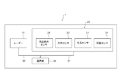
- FIG. 1 shows the outline of the structure of the radar module of this invention.
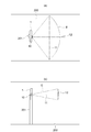
- A is a conceptual diagram for explaining the horizontal detection range of the radar in a plan view when setting the arrangement of the radar and the sensor unit
- (b) is a conceptual diagram for setting the arrangement of the radar and the sensor unit. It is a conceptual diagram explaining the vertical detection range of a radar from the side view.
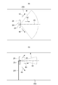
- A) is a conceptual diagram for explaining the detectable surface of the orientation sensor in a plan view when setting the arrangement of the radar and the sensor unit
- (b) is a diagram showing the arrangement of the radar and the sensor unit. It is a conceptual diagram explaining the detectable surface of an angle detection sensor from the side view at the time of setting.
- FIG. 1 is an explanatory diagram showing an outline of the configuration of the radar module of the present invention.
- the radar 10 for detecting a target the sensor unit 20 for detecting the installation position and installation direction of the radar 10 as position information
- the sensor unit 20 It includes a communication unit 30 that collects the detected position information and transmits the collected position information to an information terminal (not shown in FIG. 1).
- the sensor unit 20 detects position information regarding the installation of the radar 10.
- the communication unit 30 is connected to the sensor unit 20 by the first communication line 31.
- the position information detected by the sensor unit 20 is output from the sensor unit 20 and transmitted to the communication unit 30 via the first communication line 31.
- the radar 10 is a device that transmits a predetermined signal, reflects the transmitted signal by a target, receives the reflected signal, and detects information about the target.
- a target is a moving object on the road such as a car, a pedestrian, or a bicycle.
- a configuration in which a radar 10, that is, a radar module 1 is installed on a road accessory (for example, a traffic light, a sign, etc.) will be described.
- the horizontal detection range of the radar 10 can be appropriately selected depending on the usage conditions of the radar 10 and the like. Further, the detection range in the vertical direction of the radar 10 can be appropriately selected depending on the usage conditions of the radar 10 and the like.
- the "horizontal detection range of the radar” means the detection range of the surface parallel to the extending direction of the irradiation surface irradiated with the radio waves radiated from the radar.
- the “vertical detection range of the radar” means the detection range of the surface perpendicular to the extending direction of the irradiation surface irradiated with the radio waves radiated from the radar.
- the sensor unit 20 includes a position sensor 21 that detects the installation position of the radar 10, an orientation sensor 22 that detects the orientation of the central axis of the radiation surface of the radar 10, and an angle detection sensor that detects the angle at which the radar 10 is installed. It includes 23 and a distance sensor 24 that detects the height of the installation position of the radar 10. Further, the positional relationship between the sensor unit 20 and the radar 10 is set to a predetermined state and fixed in a predetermined state. From the above, the azimuth sensor 22 detects the angle of the radar 10 in the horizontal direction with respect to the irradiation surface of the radio waves radiated from the radar 10 on the ground.
- the angle detection sensor 23 detects the angle of the radar 10 in the direction perpendicular to the irradiation surface of the radio waves radiated from the radar 10 on the ground.
- the distance sensor 24 detects the distance between the installation position of the radar 10 and the ground located below the installation position in the direction of gravity.
- the sensor unit 20 fixed to the radar 10 in a predetermined positional relationship includes the position sensor 21, the orientation sensor 22, the angle detection sensor 23, and the distance sensor 24, so that the radar 10 is installed information from the radar 10.
- the position of the irradiation surface of the emitted radio wave on the ground can be acquired. The details of the method of setting the positional relationship between the sensor unit 20 and the radar 10 will be described later.
- the mode in which the sensor unit 20 and the radar 10 are set in a predetermined positional relationship and fixed in the predetermined positional relationship is not particularly limited.
- the radar 10 and the sensor unit 20 are formed on a flat plate or the like.
- the radar 10 and the sensor unit 20 are installed on the same fixing member, such as a storage member for accommodating the radar 10 and the sensor unit 20, in a mode in which the radar 10 and the sensor unit 20 are installed on the same plane by being placed on the support member of the above.
- the radar 10 is installed on the first fixing member such as the first storage member
- the sensor unit 20 is installed on the second fixing member such as the second storage member
- the first fixing member is connected.
- a mode in which the first fixing member and the second fixing member are set in a predetermined positional relationship and are fixed by being connected to the second fixing member at the portion can be mentioned.
- the sensor unit 20 is installed at a portion different from the radar 10 in the support member or the fixing member.
- Examples of the position sensor 21 include a GPS sensor.
- Examples of the orientation sensor 22 include a geomagnetic sensor.
- Examples of the angle detection sensor 23 include an acceleration sensor.
- Examples of the distance sensor 24 include an ultrasonic sensor.
- the communication unit 30 is also connected to the radar 10 by the second communication line 32.
- the information of the target which is a moving body detected by the radar 10, is output from the radar 10 and transmitted to the communication unit 30 via the second communication line 32. Since the communication unit 30 is connected to the radar 10 by the second communication line 32, the operation of the radar 10 can be confirmed at the information terminal connected to the communication unit 30. Therefore, when it is not necessary to check the operation of the radar 10 on the information terminal, the communication unit 30 may not be connected to the radar 10 on the second communication line 32.
- the sensor unit 20 includes the distance sensor 24, but if the height of the installation position of the radar 10 is known in advance, the distance sensor 24 may not be provided. good.
- FIG. 2A is a conceptual diagram for explaining the horizontal detection range of the radar in a plan view when setting the arrangement of the radar and the sensor unit
- FIG. 2B is a conceptual diagram showing the arrangement of the radar and the sensor unit. It is a conceptual diagram explaining the vertical detection range of a radar from the side view at the time of setting.
- FIG. 3A is a conceptual diagram for explaining the detectable surface of the orientation sensor in a plan view when setting the arrangement of the radar and the sensor unit
- FIG. 3B is a conceptual diagram of the radar and the sensor unit. It is a conceptual diagram explaining the surface that can be detected by an angle detection sensor from the side view when setting an arrangement.
- the horizontal detection range 11 of the radar 10 is relative to the extending direction of the irradiation surface 200 of the radio wave E radiated from the radar 10.
- the radar is in the parallel direction, and as shown in FIG. 2B, the vertical detection range 12 of the radar 10 is perpendicular to the extending direction of the irradiation surface 200 of the radio wave E radiated from the radar 10. 10 is installed on the support 201.
- the radiation direction of the radar 10 described above is the reference position of the radar 10.
- the detection direction 42 of the orientation sensor 22 that detects the orientation of the central axis of the radiation surface of the radar 10 is from the radar 10.
- the direction is parallel to the extending direction of the irradiation surface 200 of the emitted radio wave E, and as shown in FIG. 3B, the detection direction 43 of the angle detection sensor 23 that detects the angle at which the radar 10 is installed.
- the sensor unit 20 is installed on the support 201 so that is perpendicular to the extending direction of the irradiation surface 200 of the radio wave E radiated from the radar 10.
- the detection direction of the sensor unit 20 and the radiation direction of the radio wave E from the radar 10 are related to each other.
- the positional relationship between the sensor unit 20 and the radar 10 is set to a predetermined state and fixed in a predetermined state.
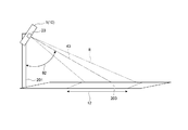
- FIG. 4 is a conceptual diagram for explaining the detection range of the laser set by the directional sensor of the radar module of the present invention in a plan view.
- FIG. 5 is a conceptual diagram for explaining the detection range of the laser set by the angle detection sensor of the radar module of the present invention from a side view.
- the orientation sensor 22 of the radar module 1 is adjusted to the detection direction 42 at a predetermined angle ⁇ 1 with respect to the N pole, so that the irradiation surface 200 of the radio wave E radiated from the radar 10 is radared. It can be set in a predetermined area on the ground along the horizontal detection range 11 of the radar 10 of the module 1. Further, as shown in FIG. 5, the angle detection sensor 23 of the radar module 1 is adjusted to the detection direction 43 having a predetermined angle ⁇ 2 with respect to the gravity direction, so that the radio wave E radiated from the radar 10 of the radar module 1 The irradiation surface 200 of the above can be set to a predetermined area on the ground along the vertical detection range 12 of the radar 10.
- the detection direction 42 of the azimuth sensor 22 and the detection direction 43 of the angle detection sensor 23 are set to predetermined directions, respectively, so that the region of the irradiation surface 200 of the radio wave E radiated from the radar 10 can be determined. Can be set in the area.
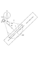
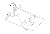
- FIG. 6 is an explanatory diagram of a state in which radio waves radiated from the radar module of the present invention are applied to a desired region of the ground.
- the orientation sensor 22 of the radar module 1 is adjusted to the detection direction 42 at a predetermined angle ⁇ 1 with respect to the N pole, so that the irradiation surface 200 of the radio wave E radiated from the radar 10 is set to the horizontal detection range 11.
- the angle detection sensor 23 of the radar module 1 can be set to a predetermined area along the line, and the angle detection sensor 23 of the radar module 1 is adjusted to the detection direction 43 of the predetermined angle ⁇ 2 with respect to the gravity direction, so that the irradiation surface 200 of the radio wave E radiated from the radar 10 can be set. Can be set in a predetermined area along the vertical detection range 12. Therefore, as shown in FIG.
- the radar module 1 is rotated along the T1 direction on the rotation axis L1 in the direction perpendicular to the irradiation surface 200 of the radio wave E, so that the horizontal detection range 11 of the radar 10 is reached.
- the irradiation surface 200 of the radio wave E radiated from the radar 10 moves along the line.
- the radar module 1 is rotated along the T2 direction on the rotation axis L2 in the direction parallel to the irradiation surface 200 of the radio wave E, so that the radar module 1 is radiated from the radar 10 along the vertical detection range 12 of the radar 10.
- the irradiation surface 200 of the radio wave E moves.
- the radar module 1 is rotated by a predetermined amount on the rotation axis L1 and rotated by a predetermined amount on the rotation axis L2, so that the irradiation surface of the radio wave E radiated from the radar 10 to a desired region on the ground. 200 is aligned.
- the radar 10 for detecting a target
- the position sensor 21 for detecting the installation position of the radar 10
- the orientation sensor 22 for detecting the orientation of the central axis of the radiation surface of the radar 10.
- the sensor unit 20 including the angle detection sensor 23 for detecting the installation angle of the radar 10 and the sensor unit 20
- the sensor unit 20 can accurately acquire information on the installation position and installation direction of the radar 10.
- the communication unit 30 that collects the position information detected by the sensor unit 20 and transmits it to the information terminal, the installation position and the installation direction of the radar 10 can be easily and accurately adjusted at the installation site of the radar 10. Can be done.
- the radar module 1 of the present invention since the structure is simple, it is possible to reduce the size and weight.
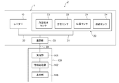
- FIG. 7 is an explanatory diagram showing an outline of the configuration of the radar module system 2 of the present invention.
- the radar module system 2 of the present invention includes a radar module 1 of the present invention and an information terminal 100 connected to a communication unit 30 of the radar module 1.
- the communication unit 30 collects the position information regarding the installation of the radar 10 detected by the sensor unit 20, and transmits the collected position information to the information terminal 100.
- the information terminal 100 receives the above-mentioned position information transmitted by the communication unit 30.
- the information terminal 100 is connected to the communication unit 30 and eventually to the radar module 1 via the third communication line 33.
- the third communication line 33 is not particularly limited, and examples thereof include wireless communication and wired communication.
- the information terminal 100 is based on the position information detected by the receiving unit 101 that receives the position information related to the installation of the radar 10 transmitted by the communication unit 30 and the sensor unit 20 that is received by the receiving unit 101.
- the information processing unit 102 that generates the installation information of the radar 10 and the display unit 103 that displays the installation information of the radar 10 generated by the information processing unit 102 are provided.
- the information processing unit 102 generates installation information of the radar 10 including the position, direction, and angle at which the radar 10 is installed, based on the position information detected by the sensor unit 20. Based on the generated installation information of the radar 10, the position information of the irradiation surface of the radio wave radiated from the radar 10 of the radar module 1 is visualized by the display unit 103 of the information terminal 100.
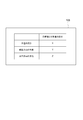
- FIG. 8 is an explanatory diagram showing an example of a first embodiment of position information in the irradiation direction of the radar detected by the sensor unit displayed by the information terminal of the radar module system of the present invention.
- the measured value in the irradiation direction of the radar 10 detected by the sensor unit 20 (the value actually measured by the sensor unit 20) and the desired value of the radar 10.
- the difference from the target value (target numerical value) indicating the irradiation direction is displayed. Specifically, with respect to the height of the installation position of the radar 10, the angle in the vertical direction, and the orientation in the horizontal direction, the difference between the measured value in the irradiation direction of the radar 10 and the target value is displayed.
- the information processing unit 102 relates to the installation information of the radar 10 which is a numerical value actually measured by the sensor unit 20 and the installation of the radar 10 which is stored in advance.
- the difference between the installation basic information of the radar 10 and the basic installation information is generated by comparing with the basic installation information (that is, the target value in the irradiation direction of the radar 10), and the display unit 103 displays the difference generated by the information processing unit 102. Is displayed.
- the installation worker of the radar 10 can display the measured values of the height of the installation position of the radar 10, the vertical angle, and the horizontal direction on the display unit 103, and the height of the installation position of the radar 10 and the vertical direction.
- the operator of the radar 10 can easily align the irradiation surface of the radar 10 with a desired region by eliminating the difference between the measured value displayed on the display unit 103 and the target value.
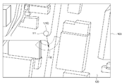
- FIG. 9 is an explanatory diagram showing an example of a second embodiment of the position information of the irradiation surface of the radar detected by the sensor unit displayed by the information terminal of the radar module system of the present invention.
- the information processing unit 102 of the information terminal 100 has the installation information of the radar 10 created based on the position information detected by the sensor unit 20. , Predetermined based on the information of the detection range in the horizontal direction of the radar 10, the information of the detection range in the vertical direction, and the characteristic information of the radar 10 including the information of the detection distance, which are stored in the information processing unit 102 in advance. With reference to the map 120, the detectable range of the radar 10 on the map 120 is determined. Based on the detectable range of the radar 10 determined by the information processing unit 102, the display unit 103 displays the actual detectable range 110 of the radar 10 on the map 120. Further, the installation position 111 of the radar 10 is also displayed on the map 120 on the display unit 103.
- the information processing unit 103 sets the detectable range of the radar 10 based on the installation information of the radar 10 created from the position information detected by the sensor unit 20. , The position where the radar 10 is installed is specified, the specified position is searched by referring to the predetermined map 120, and the display unit 103 is the specific on the predetermined map 120 searched by the information processing unit 103. The detectable range of the radar 10 is displayed at the position.
- the operator of the radar 10 installs the radar module 1 by a predetermined amount on the rotation axis in the direction perpendicular to the irradiation surface while checking the detectable range 110 of the radar 10 on the map 120 displayed on the display unit 103.
- the detectable range 110 of the radar 10 is aligned with a desired region on the map 120.
- the operator of the radar 10 easily adjusts the irradiation surface of the radar 10 to a desired area by aligning the detectable range 110 of the radar 10 with a desired area on the map 120 while checking the display unit 103. can do.
- Examples of the information terminal 100 include information terminals that are easy to carry, such as smartphones, tablet-type personal computers, and notebook-type personal computers.
- the radar 10 is installed by including the radar module 1 and the information terminal 100 that receives the position information regarding the installation of the radar 10 transmitted by the communication unit 30 of the radar module 1.
- the operator can easily and accurately grasp the information on the installation position and installation direction of the radar 10 from the information terminal 100.
- the installation worker of the radar 10 can easily and accurately grasp the information on the installation position and the installation direction of the radar 10 at the installation site of the radar 10. The efficiency of installation work is improved.
- the sensor unit detects a position sensor that detects the installation position of the radar, an orientation sensor that detects the orientation of the central axis of the radiation surface of the radar, and an angle at which the radar is installed. It was equipped with an angle detection sensor. Instead of this, the installation position of the radar is determined in advance, the radar installation worker is carrying a position sensor, etc., and the angle at which the radar is installed can be determined in advance.
- the sensor unit is the central axis of the radiation surface of the radar even if it does not have a position sensor and an angle detection sensor. If it is equipped with an orientation sensor that detects the orientation of the radar, it is possible to accurately acquire information on the radar installation position and installation direction. Therefore, in the above case, the sensor unit may include an orientation sensor.
- the sensor unit determines the position sensor for detecting the installation position of the radar, the direction sensor for detecting the direction of the central axis of the radiation surface of the radar, and the angle at which the radar is installed. It was equipped with an angle detection sensor for detection. Instead of this, if the installation position of the radar is determined in advance and the radar installation worker is carrying a position sensor, the sensor unit does not have to have a position sensor, but the radar. If it is equipped with an orientation sensor that detects the orientation of the central axis of the radiation surface and an angle detection sensor that detects the angle at which the radar is installed, it is possible to accurately acquire information on the installation position and installation direction of the radar. Therefore, in the above case, the sensor unit may include a directional sensor and an angle detection sensor.
- the sensor unit determines the position sensor for detecting the installation position of the radar, the direction sensor for detecting the direction of the central axis of the radiation surface of the radar, and the angle at which the radar is installed. It was equipped with an angle detection sensor for detection. Instead of this, if it is possible to determine the angle at which the radar is installed in advance, and if the angle at which the radar is installed can be designed and fixed in advance when assembling the radar module, the sensor unit detects the angle. Even if you do not have a sensor, if you have an orientation sensor that detects the orientation of the central axis of the radar's radiation surface and a position sensor that detects the radar installation position, you can accurately obtain information on the radar installation position and installation direction. You can get it. Therefore, in the above case, the sensor unit may include a directional sensor and a position sensor.
- a support member or a fixing member was used as a fixing means for the radar and the sensor unit, but the fixing means for the radar and the sensor unit may be moved by remote control. That is, when the radar installation worker aligns the irradiation surface of the radar with a desired area based on the actual position information of the radar displayed on the display unit of the information terminal, the display unit of the information terminal is viewed. However, by remote control such as remote control, the radar module is rotated by a predetermined amount on the rotation axis in the direction perpendicular to the irradiation surface, and is rotated by a predetermined amount on the rotation axis in the direction parallel to the irradiation surface. You may let me.
- the difference between the measured value of the radar irradiation direction detected by the sensor unit and the target value indicating the desired irradiation direction of the radar is displayed.
- the measured value of the radar irradiation direction detected by the sensor unit may be displayed, and the measured value of the radar irradiation direction detected by the sensor unit and the desired irradiation direction of the radar may be displayed. It may be a mode to display the target value indicating.
- the radar module of the present invention can easily and accurately adjust the installation position and direction of the radar at the installation site of the radar, for example, the movement of moving objects on the road such as pedestrians and vehicles at intersections. It can be used in the field of road monitoring equipment to detect.
- Radar module 2 Radar module system 10 Radar 11 Horizontal detection range 12 Vertical detection range 20 Sensor unit 21 Position sensor 22 Orientation sensor 23 Angle detection sensor 24 Distance sensor 30 Communication unit 100 Information terminal
Landscapes
- Engineering & Computer Science (AREA)
- Physics & Mathematics (AREA)
- Radar, Positioning & Navigation (AREA)
- Remote Sensing (AREA)
- General Physics & Mathematics (AREA)
- Computer Networks & Wireless Communication (AREA)
- Electromagnetism (AREA)
- Radar Systems Or Details Thereof (AREA)
Abstract
レーダーの設置現場にて、レーダーの設置位置や設置方向を容易且つ正確に調整することができ、また、小型化、軽量化されたレーダーモジュールを提供する。 物標を検知するレーダーと、前記レーダーの放射面の中心軸の方位を検出する方位センサを備えたセンサ部と、前記センサ部が検出した位置情報を収集し、収集した前記位置情報を情報端末へ送信する通信部と、を備えたレーダーモジュール。
Description
本発明は、地面上の物標を検知するレーダーとレーダーの検知位置を検出するセンサ部とを備えたレーダーモジュール、及びレーダーモジュールとレーダーモジュールの位置情報を受信する情報端末とを備えたレーダーモジュールシステムに関するものである。
道路監視装置として、道路脇等の道路付近にレーダーを設置することが検討されている。例えば、レーダーによるセンシングシステムにて、車、歩行者、自転車といった道路上の移動体の動きを監視し、移動体の動きに応じて、運転者や歩行者に、照明による表示や無線通信による通知等の警告手段にて、道路上の危険状況や交通状況を伝達することが検討されている。上記したレーダーによるセンシングシステムを道路上に適用することで、交通事故の防止、交通渋滞の緩和といった安全、快適な道路交通を実現することができる。
ここで、レーダーを道路附属物(例えば、信号機、標識など)に設置して、道路を監視するシステムにおいて、道路上の危険状況や交通状況を正確に把握するために、レーダーから放射される電波が、道路や道路の周辺部の所望の領域に正確に照射されることが必要となる。従って、道路附属物に設置したレーダーの設置位置や設置方向にずれが生じることを防止するために、レーダーの稼働にあたり、レーダーの設置位置や設置方向を調整することが必要となる。
レーダーの設置位置や設置方向を調整するために、事前にレーダーの取り付け高さや画角を設計しておいてから該設計に基づいてレーダーを設置する場合、レーダーの設置現場では、レーダーの取り付け位置合わせのための高さ計測作業、画角計測作業、方位計測作業が、それぞれ必要となり、レーダーの設置作業が繁雑であるという問題があった。
そこで、カメラとレーダーが一体となった道路監視装置が提案されている(特許文献1)。特許文献1では、カメラの画像情報とレーダーの設置情報を用いて、カメラの撮影画像中の白線などに沿って、レーダーの座標系に基線を引き、レーダーの設置情報の基線がカメラの画像情報の白線などに対してずれが生じている場合には、レーダーの設置情報を更新して白線と基線を一致させる。すなわち、カメラの画像情報に基づいてレーダーの設置位置や設置方向を調整することで、レーダーの設置位置や設置方向を正確に調整するものである。
しかし、特許文献1では、レーダーの他にカメラを搭載し、カメラの画像情報に基づいてレーダーの設置位置や設置方向を調整する調整手段も必要となるので、装置が複雑化してしまうという問題があった。また、道路監視装置は、道路付近のポール等といった他の設備に併設される場合があることから、小型化、軽量化が要求される。しかし、レーダーの他にカメラを搭載する特許文献1の装置では、大型化、重量化してしまうという問題があった。
上記事情に鑑み、本発明は、レーダーの設置現場にて、レーダーの設置位置や設置方向を容易且つ正確に調整することができ、また、小型化、軽量化されたレーダーモジュールを提供することを目的とする。
本発明の構成の要旨は、以下の通りである。
[1]物標を検知するレーダーと、
前記レーダーの放射面の中心軸の方位を検出する方位センサを備えたセンサ部と、
前記センサ部が検出した位置情報を収集し、収集した前記位置情報を情報端末へ送信する通信部と、
を備えたレーダーモジュール。
[2]前記レーダーの放射面の中心軸の方位を検出する方位センサと、前記レーダーの設置されている角度を検出する角度検出センサと、を備えたセンサ部と、
前記センサ部が検出した位置情報を収集し、収集した前記位置情報を情報端末へ送信する通信部と、
を備えた[1]に記載のレーダーモジュール。
[3]前記レーダーの設置位置を検出する位置センサと、前記レーダーの放射面の中心軸の方位を検出する方位センサと、を備えたセンサ部と、
前記センサ部が検出した位置情報を収集し、収集した前記位置情報を情報端末へ送信する通信部と、
を備えた[1]に記載のレーダーモジュール。
[4]前記レーダーの設置位置を検出する位置センサと、前記レーダーの放射面の中心軸の方位を検出する方位センサと、前記レーダーの設置されている角度を検出する角度検出センサと、を備えたセンサ部と、
前記センサ部が検出した位置情報を収集し、収集した前記位置情報を情報端末へ送信する通信部と、
を備えた[1]に記載のレーダーモジュール。
[5]前記センサ部が、さらに、前記レーダーの設置位置の高さを検出する距離センサを備えた[1]乃至[4]のいずれか1つに記載のレーダーモジュール。
[6]前記レーダーと前記センサ部が、同一平面上に設置されている[1]乃至[5]のいずれか1つに記載のレーダーモジュール。
[7]前記レーダーと前記センサ部が、同一の固定部材に設置されている[1]乃至[6]のいずれか1つに記載のレーダーモジュール。
[8]前記レーダーが、第1の固定部材に設置され、前記センサ部が、第2の固定部材に設置され、前記第1の固定部材が連結部にて前記第2の固定部材と連結されている[1]乃至[6]のいずれか1つに記載のレーダーモジュール。
[9]前記物標が、道路上の移動体である[1]乃至[8]のいずれか1つに記載のレーダーモジュール。
[10]物標を検知するレーダーと、
前記レーダーの放射面の中心軸の方位を検出する方位センサを備えたセンサ部と、
前記センサ部が検出した位置情報を収集し、収集した前記位置情報を外部へ送信する通信部と、
を備えたレーダーモジュールと、
前記通信部が送信した前記位置情報を受信する情報端末と、を備えたレーダーモジュールシステム。
[11]前記レーダーの放射面の中心軸の方位を検出する方位センサと、前記レーダーの設置されている角度を検出する角度検出センサと、を備えたセンサ部と、
前記センサ部が検出した位置情報を収集し、収集した前記位置情報を外部へ送信する通信部と、
を備えた[10]に記載のレーダーモジュールシステム。
[12]前記レーダーの設置位置を検出する位置センサと、前記レーダーの放射面の中心軸の方位を検出する方位センサと、を備えたセンサ部と、
前記センサ部が検出した位置情報を収集し、収集した前記位置情報を外部へ送信する通信部と、
を備えた[10]に記載のレーダーモジュールシステム。
[13]前記レーダーの設置位置を検出する位置センサと、前記レーダーの放射面の中心軸の方位を検出する方位センサと、前記レーダーの設置されている角度を検出する角度検出センサと、を備えたセンサ部と、
前記センサ部が検出した位置情報を収集し、収集した前記位置情報を外部へ送信する通信部と、
を備えた[10]に記載のレーダーモジュールシステム。
[14]前記情報端末が、前記通信部が送信した前記位置情報を受信する受信部と、前記受信部が受信した前記位置情報に基づいて、前記レーダーの設置情報を生成する情報処理部と、前記情報処理部により生成された設置情報を表示する表示部と、を備える[10]乃至[13]のいずれか1つに記載のレーダーモジュールシステム。
[15]前記情報処理部が、前記センサ部が検出した前記位置情報に基づいて、前記レーダーが設置されている位置と方位と角度とを含む前記設置情報を生成する[14]に記載のレーダーモジュールシステム。
[16]前記情報処理部が、前記レーダーの設置情報と、予め記憶されている、前記レーダーの設置に関する設置基本情報とを比較し、前記レーダーの設置情報と前記設置基本情報との差分を生成し、
前記表示部が、前記情報処理部により生成された差分を表示する[14]または[15]に記載のレーダーモジュールシステム。
[17]前記情報処理部が、
前記レーダーの設置情報に基づいて、前記レーダーの検知可能範囲と、前記レーダーが設置されている位置を特定し、
所定のマップを参照して、特定した位置を検索し、
前記表示部は、前記情報処理部により検索された前記所定のマップ上の特定の位置に、前記レーダーの検知可能範囲を表示する[14]または[15]に記載のレーダーモジュールシステム。
本明細書中、「レーダーの放射面の中心軸」とは、レーダーから放射される電波の放射面に対し、レーダーにおけるレーダー放射部にて垂直に交わる中心軸を意味する。また、本明細書では、レーダーが検知する物標の検知範囲について、センサ部が検出する、レーダーの放射面の中心軸の方位に関する情報、レーダーの設置されている角度に関する情報、レーダーの設置位置に関する情報及びレーダーの設置位置の高さに関する情報のうち、1つ以上の情報を「位置情報」と総称する。
本発明のレーダーモジュールの態様によれば、物標を検知するレーダーと、レーダーの放射面の中心軸の方位を検出する方位センサを備えたセンサ部と、センサ部が検出した位置情報を収集し情報端末へ送信する通信部と、を備えることにより、センサ部がレーダーの設置位置や設置方向の情報を正確に取得できるので、レーダーの設置現場にて、レーダーの設置位置や設置方向を容易且つ正確に調整することができ、また、小型化、軽量化されたレーダーモジュールとすることができる。本発明のレーダーモジュールの態様によれば、物標を検知するレーダーと、レーダーの設置位置を検出する位置センサとレーダーの放射面の中心軸の方位を検出する方位センサとレーダーの設置されている角度を検出する角度検出センサとを備えたセンサ部と、センサ部が検出した位置情報を収集し情報端末へ送信する通信部と、を備えることにより、センサ部がレーダーの設置位置や設置方向の情報を正確に取得できるので、レーダーの設置現場にて、レーダーの設置位置や設置方向を容易且つ正確に調整することができ、また、小型化、軽量化されたレーダーモジュールとすることができる。
本発明のレーダーモジュールの態様によれば、センサ部が、さらに、レーダーの設置位置の高さを検出する距離センサを備えることにより、レーダーモジュールの設置位置の高さを検出できるので、レーダーモジュールを設置する位置の高さが予め判明していなくても、レーダーの設置位置や設置方向を容易且つ正確に調整することができる。
本発明のレーダーモジュールシステムの態様によれば、物標を検知するレーダーと、レーダーの設置位置を検出する位置センサとレーダーの放射面の中心軸の方位を検出する方位センサとレーダーの設置されている角度を検出する角度検出センサとを備えたセンサ部と、センサ部が検出した位置情報を収集し外部へ送信する通信部と、を備えたレーダーモジュールと、通信部が送信した位置情報を受信する情報端末と、を備えることにより、レーダーの設置作業者は情報端末からレーダーの設置位置や設置方向の情報を容易且つ正確に把握することができる。また、本発明のレーダーモジュールシステムの態様によれば、レーダーの設置作業者は、レーダーの設置現場にて、レーダーの設置位置や設置方向の情報を容易且つ正確に把握できるので、レーダー設置作業の効率が向上する。
以下に、本発明のレーダーモジュールについて、図面を用いながら説明する。図1は、本発明のレーダーモジュールの構成の概要を示す説明図である。
図1に示すように、本発明のレーダーモジュール1は、物標を検知するレーダー10と、レーダー10の設置位置や設置方向の設置情報を位置情報として検出するセンサ部20と、センサ部20が検出した位置情報を収集し、収集した位置情報を情報端末(図1では、図示せず)へ送信する通信部30と、を備えている。センサ部20は、レーダー10の設置に関する位置情報を検出する。通信部30は、第1の通信線31にてセンサ部20と接続されている。センサ部20が検出した位置情報は、センサ部20から出力されて、第1の通信線31を介して通信部30へ送信される。
レーダー10は、所定の信号を送信し、送信した信号が物標によって反射され、この反射された信号を受信して、当該物標に関する情報を検出する装置である。物標とは、例えば、自動車、歩行者、自転車といった道路上の移動体である。本発明では、道路附属物(例えば、信号機、標識など)に、レーダー10、すなわち、レーダーモジュール1が設置される構成について説明する。レーダー10の水平方向の検知範囲としては、レーダー10の使用条件等によって適宜選択可能である。また、レーダー10の垂直方向の検知範囲としては、レーダー10の使用条件等によって適宜選択可能である。なお、本明細書中、「レーダーの水平検知範囲」とは、レーダーから放射された電波が照射される照射面の延在方向に対し平行方向の面の検知範囲を意味する。また、「レーダーの垂直検知範囲」とは、レーダーから放射された電波が照射される照射面の延在方向に対し垂直方向の面の検知範囲を意味する。
センサ部20は、レーダー10の設置位置を検出する位置センサ21と、レーダー10の放射面の中心軸の方位を検出する方位センサ22と、レーダー10の設置されている角度を検出する角度検出センサ23と、レーダー10の設置位置の高さを検出する距離センサ24と、を備えている。また、センサ部20とレーダー10の位置関係は、所定の状態に設定され、且つ所定の状態にて固定されている。上記から、方位センサ22は、レーダー10から放射された電波の地上における照射面に対して水平方向のレーダー10の角度を検知する。角度検出センサ23は、レーダー10から放射された電波の地上における照射面に対して垂直方向のレーダー10の角度を検知する。距離センサ24は、レーダー10の設置位置と該設置位置から重力方向下方に位置する地面との距離を検知する。
レーダー10と所定の位置関係に固定されているセンサ部20が、位置センサ21と方位センサ22と角度検出センサ23と距離センサ24とを備えることで、レーダー10の設置情報である、レーダー10から放射された電波の地上における照射面の位置を取得することができる。なお、センサ部20とレーダー10の位置関係の設定方法の詳細については、後述する。
センサ部20とレーダー10が、所定の位置関係に設定され、且つ所定の位置関係にて固定される態様としては、特に限定されず、例えば、レーダー10とセンサ部20が、平板状の基板等の支持部材に載置されることで同一平面上に設置されている態様、レーダー10とセンサ部20が、レーダー10とセンサ部20を収納する収納部材等、同一の固定部材に設置されている態様、レーダー10が、第1の収納部材等の第1の固定部材に設置され、センサ部20が、第2の収納部材等の第2の固定部材に設置され、第1の固定部材が連結部にて第2の固定部材と連結されていることで、第1の固定部材と第2の固定部材が所定の位置関係に設定され、且つ固定されている態様等が挙げられる。上記態様では、センサ部20は、支持部材または固定部材において、レーダー10とは異なる部位に設置されている。
位置センサ21としては、例えば、GPSセンサが挙げられる。方位センサ22としては、例えば、地磁気センサが挙げられる。角度検出センサ23としては、例えば、加速度センサが挙げられる。距離センサ24としては、例えば、超音波センサが挙げられる。
なお、図1のレーダーモジュール1では、通信部30は、第2の通信線32にてレーダー10とも接続されている。レーダー10が検知した移動体である物標の情報は、レーダー10から出力されて、第2の通信線32を介して通信部30へ送信される。通信部30が第2の通信線32にてレーダー10と接続されていることで、通信部30と接続されている情報端末にて、レーダー10の動作確認をすることができる。従って、情報端末にて、レーダー10の動作確認をする必要がない場合には、通信部30は第2の通信線32にてレーダー10と接続されていなくてもよい。
また、図1のレーダーモジュール1では、センサ部20は距離センサ24を備えているが、レーダー10の設置位置の高さが予め判明している場合には、距離センサ24を備えていなくてもよい。
次に、センサ部20とレーダー10の位置関係の設定方法について、図面を用いながら説明する。図2(a)は、レーダーとセンサ部の配置を設定する際の、レーダーの水平検知範囲を平面視にて説明する概念図であり、図2(b)は、レーダーとセンサ部の配置を設定する際の、レーダーの垂直検知範囲を側面視にて説明する概念図である。図3(a)は、レーダーとセンサ部の配置を設定する際の、方位センサの検知可能な面を平面視にて説明する概念図であり、図3(b)は、レーダーとセンサ部の配置を設定する際の、角度検出センサの検知可能な面を側面視にて説明する概念図である。
レーダー10とセンサ部20の位置関係を設定するにあたり、図2(a)に示すように、レーダー10の水平検知範囲11がレーダー10から放射された電波Eの照射面200の延在方向に対し平行方向となり、且つ、図2(b)に示すように、レーダー10の垂直検知範囲12がレーダー10から放射された電波Eの照射面200の延在方向に対し垂直方向となるように、レーダー10を支持体201に設置する。上記したレーダー10の放射方向が、レーダー10の基準位置である。
さらに、レーダー10とセンサ部20の位置関係を設定するにあたり、図3(a)に示すように、レーダー10の放射面の中心軸の方位を検出する方位センサ22の検知方向42がレーダー10から放射された電波Eの照射面200の延在方向に対し平行方向となり、且つ、図3(b)に示すように、レーダー10の設置されている角度を検出する角度検出センサ23の検知方向43がレーダー10から放射された電波Eの照射面200の延在方向に対し垂直方向となるように、センサ部20を支持体201に設置する。上記のようにして、センサ部20とレーダー10の位置関係が設定されることで、センサ部20の検知方向とレーダー10からの電波Eの放射方向が関連づけられる。結果、センサ部20とレーダー10の位置関係は、所定の状態に設定され、且つ所定の状態にて固定されていることとなる。
次に、センサ部20の検知方向とレーダー10からの電波Eの放射方向との関係について図面を用いながら説明する。図4は、本発明のレーダーモジュールの方位センサで設定されたレーザーの検知範囲を平面視にて説明する概念図である。図5は、本発明のレーダーモジュールの角度検出センサで設定されたレーザーの検知範囲を側面視にて説明する概念図である。
図4に示すように、レーダーモジュール1の方位センサ22が、N極に対して所定角度θ1の検知方向42に調整されることで、レーダー10から放射された電波Eの照射面200を、レーダーモジュール1のレーダー10の水平検知範囲11に沿って地面上の所定の領域に設定できる。また、図5に示すように、レーダーモジュール1の角度検出センサ23が、重力方向に対して所定角度θ2の検知方向43に調整されることで、レーダーモジュール1のレーダー10から放射された電波Eの照射面200を、レーダー10の垂直検知範囲12に沿って地面上の所定の領域に設定できる。上記から、方位センサ22の検知方向42と角度検出センサ23の検知方向43が、それぞれ、所定の方向に設定されることで、レーダー10から放射された電波Eの照射面200の領域を所定の領域に設定できる。
次に、レーダー10から放射された電波Eの照射面200を所望の領域に設定する方法について図面を用いながら説明する。図6は、本発明のレーダーモジュールから放射された電波が、地面の所望の領域に照射された状態の説明図である。
上記の通り、レーダーモジュール1の方位センサ22が、N極に対して所定角度θ1の検知方向42に調整されることで、レーダー10から放射された電波Eの照射面200を水平検知範囲11に沿って所定の領域に設定でき、レーダーモジュール1の角度検出センサ23が、重力方向に対して所定角度θ2の検知方向43に調整されることで、レーダー10から放射された電波Eの照射面200を垂直検知範囲12に沿って所定の領域に設定できる。従って、図6に示すように、レーダーモジュール1が電波Eの照射面200に対して垂直方向の回転軸L1にてT1方向に沿って回動されることで、レーダー10の水平検知範囲11に沿ってレーダー10から放射された電波Eの照射面200が移動する。また、レーダーモジュール1が電波Eの照射面200に対して平行方向の回転軸L2にてT2方向に沿って回動されることで、レーダー10の垂直検知範囲12に沿ってレーダー10から放射された電波Eの照射面200が移動する。上記から、レーダーモジュール1が、回転軸L1にて所定量回動され、回転軸L2にて所定量回動されることで、地面の所望の領域にレーダー10から放射された電波Eの照射面200が位置合わせされる。
上記から、本発明のレーダーモジュール1によれば、物標を検知するレーダー10と、レーダー10の設置位置を検出する位置センサ21とレーダー10の放射面の中心軸の方位を検出する方位センサ22とレーダー10の設置されている角度を検出する角度検出センサ23とを備えたセンサ部20と、を備えることにより、センサ部20がレーダー10の設置位置や設置方向の情報を正確に取得できる。また、センサ部20が検出した位置情報を収集し情報端末へ送信する通信部30を備えることにより、レーダー10の設置現場にて、レーダー10の設置位置や設置方向を容易且つ正確に調整することができる。また、本発明のレーダーモジュール1によれば、構造が簡易なので、小型化、軽量化が可能となる。
次に、本発明のレーダーモジュールを有するレーダーモジュールシステムについて説明する。図7は、本発明のレーダーモジュールシステム2の構成の概要を示す説明図である。
図7に示すように、本発明のレーダーモジュールシステム2は、本発明のレーダーモジュール1と、レーダーモジュール1の通信部30に接続された情報端末100とを備えている。上記の通り、通信部30は、センサ部20が検出したレーダー10の設置に関する位置情報を収集し、収集した位置情報を情報端末100へ送信する。情報端末100は、通信部30が送信した上記位置情報を受信する。
情報端末100は、第3の通信線33を介して通信部30、ひいては、レーダーモジュール1と接続されている。第3の通信線33としては、特に限定されず、無線通信、有線通信等が挙げられる。
図7に示すように、情報端末100は、通信部30が送信したレーダー10の設置に関する位置情報を受信する受信部101と、受信部101が受信したセンサ部20の検出した位置情報に基づいて、レーダー10の設置情報を生成する情報処理部102と、情報処理部102により生成されたレーダー10の設置情報を表示する表示部103と、を備えている。情報処理部102は、センサ部20が検出した位置情報に基づいて、レーダー10が設置されている位置と方位と角度とを含むレーダー10の設置情報を生成する。生成されたレーダー10の設置情報に基づいて、レーダーモジュール1のレーダー10から放射された電波の照射面の位置情報が、情報端末100の表示部103によって可視化される。
次に、情報端末100の表示部103の表示方法例について図面を用いながら説明する。まず、表示部103の表示方法の第1実施形態例を説明する。図8は、本発明のレーダーモジュールシステムの情報端末が表示する、センサ部が検出したレーダーの照射方向の位置情報の第1実施形態例を示す説明図である。
図8に示すように、表示部103の表示方法の第1実施形態例では、センサ部20が検出したレーダー10の照射方向の計測値(センサ部20が実測した数値)とレーダー10の所望の照射方向を示す目標値(目的とする数値)との差分が表示されている。具体的には、レーダー10の設置位置の高さ、垂直方向の角度及び水平方向の方位について、レーダー10の照射方向の計測値と目標値との差分が、それぞれ、が表示されている。
上記から、表示部103の表示方法の第1実施形態例では、情報処理部102が、センサ部20が実測した数値であるレーダー10の設置情報と、予め記憶されている、レーダー10の設置に関する設置基本情報(すなわち、レーダー10の照射方向の目標値)とを比較し、レーダー10の設置情報と設置基本情報との差分を生成し、表示部103が、情報処理部102により生成された差分を表示する。
レーダー10の設置作業者は、レーダー10の設置位置の高さ、垂直方向の角度及び水平方向の方位の計測値が、表示部103に表示されているレーダー10の設置位置の高さ、垂直方向の角度及び水平方向の方位の目標値に合致するよう、すなわち、表示部103に表示される計測値と目標値との差分がなくなるよう、レーダーモジュール1を、照射面に対して垂直方向の回転軸にて所定量回動させ、また、照射面に対して平行方向の回転軸にて所定量回動させる。レーダー10の設置作業者は、表示部103に表示される計測値と目標値との差分がなくなるようにすることで、所望の領域にレーダー10の照射面を容易に位置合わせすることができる。
次に、表示部103の表示方法の第2実施形態例を説明する。図9は、本発明のレーダーモジュールシステムの情報端末が表示する、センサ部が検出したレーダーの照射面の位置情報の第2実施形態例を示す説明図である。
図9に示すように、表示部103の表示方法の第2実施形態例では、情報端末100の情報処理部102が、センサ部20が検出した位置情報に基づいて作成したレーダー10の設置情報と、予め情報処理部102に記憶されている、レーダー10の水平方向の検知範囲の情報と垂直方向の検知範囲の情報と検知距離の情報を含むレーダー10の特性情報と、に基づいて、所定のマップ120を参照して、マップ120上におけるレーダー10の検知可能範囲を判定する。情報処理部102で判定されたレーダー10の検知可能範囲に基づいて、表示部103が、レーダー10の実際の検知可能範囲110をマップ120上に表示する。また、表示部103には、レーダー10の設置位置111もマップ120上に表示されている。
上記から、表示部103の表示方法の第2実施形態例では、情報処理部103は、センサ部20が検出した位置情報から作成したレーダー10の設置情報に基づいて、レーダー10の検知可能範囲と、レーダー10が設置されている位置を特定し、所定のマップ120を参照して、特定した位置を検索し、表示部103は、情報処理部103により検索された所定のマップ120上の特定の位置に、レーダー10の検知可能範囲を表示する。
レーダー10の設置作業者は、表示部103に表示されるマップ120上のレーダー10の検知可能範囲110を確認しながら、レーダーモジュール1を、照射面に対して垂直方向の回転軸にて所定量回動させ、また、照射面に対して平行方向の回転軸にて所定量回動させることにより、レーダー10の検知可能範囲110をマップ120上の所望の領域に位置合わせする。レーダー10の設置作業者は、表示部103を確認しながらレーダー10の検知可能範囲110をマップ120上の所望の領域に位置合わせすることにより、所望の領域にレーダー10の照射面を容易に調整することができる。
情報端末100としては、例えば、スマートフォン、タブレット型のパーソナルコンピュータ、ノート型パーソナルコンピュータ等、携帯が容易な情報端末を挙げることができる。
本発明のレーダーモジュールシステム2によれば、レーダーモジュール1と、レーダーモジュール1の通信部30が送信したレーダー10の設置に関する位置情報を受信する情報端末100と、を備えることにより、レーダー10の設置作業者は情報端末100からレーダー10の設置位置や設置方向の情報を容易且つ正確に把握することができる。また、本発明のレーダーモジュールシステム2によれば、レーダー10の設置作業者は、レーダー10の設置現場にて、レーダー10の設置位置や設置方向の情報を容易且つ正確に把握できるので、レーダー10の設置作業の効率が向上する。
次に、本発明のレーダーモジュール及びレーダーモジュールシステムの他の実施形態について説明する。上記レーダーモジュール及びレーダーモジュールシステムでは、センサ部は、レーダーの設置位置を検出する位置センサと、レーダーの放射面の中心軸の方位を検出する方位センサと、レーダーの設置されている角度を検出する角度検出センサと、を備えていた。これに代えて、レーダーの設置位置が事前に決められており、レーダーの設置作業者が位置センサを携行している等の場合であり、且つレーダーの設置される角度を事前に決めることが可能であり、レーダーモジュールの組み立て時にレーダーの設置される角度を予め設計し固定できる等の場合には、センサ部は、位置センサと角度検出センサを備えていなくても、レーダーの放射面の中心軸の方位を検出する方位センサを備えていれば、レーダーの設置位置や設置方向の情報を正確に取得できる。従って、上記の場合には、センサ部は、方位センサを備えていればよい。
また、上記レーダーモジュール及びレーダーモジュールシステムでは、センサ部は、レーダーの設置位置を検出する位置センサと、レーダーの放射面の中心軸の方位を検出する方位センサと、レーダーの設置されている角度を検出する角度検出センサと、を備えていた。これに代えて、レーダーの設置位置が事前に決められており、レーダーの設置作業者が位置センサを携行している等の場合には、センサ部は、位置センサを備えていなくても、レーダーの放射面の中心軸の方位を検出する方位センサとレーダーの設置されている角度を検出する角度検出センサを備えていれば、レーダーの設置位置や設置方向の情報を正確に取得できる。従って、上記の場合には、センサ部は、方位センサと角度検出センサを備えていればよい。
また、上記レーダーモジュール及びレーダーモジュールシステムでは、センサ部は、レーダーの設置位置を検出する位置センサと、レーダーの放射面の中心軸の方位を検出する方位センサと、レーダーの設置されている角度を検出する角度検出センサと、を備えていた。これに代えて、レーダーの設置される角度を事前に決めることが可能であり、レーダーモジュールの組み立て時にレーダーの設置される角度を予め設計し固定できる等の場合には、センサ部は、角度検出センサを備えていなくても、レーダーの放射面の中心軸の方位を検出する方位センサとレーダーの設置位置を検出する位置センサを備えていれば、レーダーの設置位置や設置方向の情報を正確に取得できる。従って、上記の場合には、センサ部は、方位センサと位置センサを備えていればよい。
上記レーダーモジュールでは、レーダーとセンサ部の固定手段として支持部材や固定部材が用いられていたが、レーダーとセンサ部の上記固定手段は、遠隔操作にて、動かせる態様としてもよい。すなわち、レーダーの設置作業者が、情報端末の表示部に表示されるレーダーの実際の位置情報に基づいて、所望の領域にレーダーの照射面を位置合わせする際に、情報端末の表示部を見ながら、リモートコントロール等の遠隔操作にて、レーダーモジュールを照射面に対して垂直方向の回転軸にて所定量回動させ、また、照射面に対して平行方向の回転軸にて所定量回動させてもよい。
上記レーダーモジュールシステムでは、情報端末の表示部の表示方法の第1実施形態例では、センサ部が検出したレーダーの照射方向の計測値とレーダーの所望の照射方向を示す目標値との差分が表示されていたが、これに代えて、センサ部が検出したレーダーの照射方向の計測値のみを表示する態様としてもよく、センサ部が検出したレーダーの照射方向の計測値とレーダーの所望の照射方向を示す目標値とを表示する態様としてもよい。
本発明のレーダーモジュールは、レーダーの設置現場にて、レーダーの設置位置や設置方向を容易且つ正確に調整することができるので、例えば、交差点における歩行者や車両等、道路上の移動体の動きを検出する道路監視装置の分野で利用することができる。
1 レーダーモジュール
2 レーダーモジュールシステム
10 レーダー
11 水平検知範囲
12 垂直検知範囲
20 センサ部
21 位置センサ
22 方位センサ
23 角度検出センサ
24 距離センサ
30 通信部
100 情報端末
2 レーダーモジュールシステム
10 レーダー
11 水平検知範囲
12 垂直検知範囲
20 センサ部
21 位置センサ
22 方位センサ
23 角度検出センサ
24 距離センサ
30 通信部
100 情報端末
Claims (17)
- 物標を検知するレーダーと、
前記レーダーの放射面の中心軸の方位を検出する方位センサを備えたセンサ部と、
前記センサ部が検出した位置情報を収集し、収集した前記位置情報を情報端末へ送信する通信部と、
を備えたレーダーモジュール。 - 前記レーダーの放射面の中心軸の方位を検出する方位センサと、前記レーダーの設置されている角度を検出する角度検出センサと、を備えたセンサ部と、
前記センサ部が検出した位置情報を収集し、収集した前記位置情報を情報端末へ送信する通信部と、
を備えた請求項1に記載のレーダーモジュール。 - 前記レーダーの設置位置を検出する位置センサと、前記レーダーの放射面の中心軸の方位を検出する方位センサと、を備えたセンサ部と、
前記センサ部が検出した位置情報を収集し、収集した前記位置情報を情報端末へ送信する通信部と、
を備えた請求項1に記載のレーダーモジュール。 - 前記レーダーの設置位置を検出する位置センサと、前記レーダーの放射面の中心軸の方位を検出する方位センサと、前記レーダーの設置されている角度を検出する角度検出センサと、を備えたセンサ部と、
前記センサ部が検出した位置情報を収集し、収集した前記位置情報を情報端末へ送信する通信部と、
を備えた請求項1に記載のレーダーモジュール。 - 前記センサ部が、さらに、前記レーダーの設置位置の高さを検出する距離センサを備えた請求項1乃至4のいずれか1項に記載のレーダーモジュール。
- 前記レーダーと前記センサ部が、同一平面上に設置されている請求項1乃至5のいずれか1項に記載のレーダーモジュール。
- 前記レーダーと前記センサ部が、同一の固定部材に設置されている請求項1乃至6のいずれか1項に記載のレーダーモジュール。
- 前記レーダーが、第1の固定部材に設置され、前記センサ部が、第2の固定部材に設置され、前記第1の固定部材が連結部にて前記第2の固定部材と連結されている請求項1乃至6のいずれか1項に記載のレーダーモジュール。
- 前記物標が、道路上の移動体である請求項1乃至8のいずれか1項に記載のレーダーモジュール。
- 物標を検知するレーダーと、
前記レーダーの放射面の中心軸の方位を検出する方位センサを備えたセンサ部と、
前記センサ部が検出した位置情報を収集し、収集した前記位置情報を外部へ送信する通信部と、
を備えたレーダーモジュールと、
前記通信部が送信した前記位置情報を受信する情報端末と、を備えたレーダーモジュールシステム。 - 前記レーダーの放射面の中心軸の方位を検出する方位センサと、前記レーダーの設置されている角度を検出する角度検出センサと、を備えたセンサ部と、
前記センサ部が検出した位置情報を収集し、収集した前記位置情報を外部へ送信する通信部と、
を備えた請求項10に記載のレーダーモジュールシステム。 - 前記レーダーの設置位置を検出する位置センサと、前記レーダーの放射面の中心軸の方位を検出する方位センサと、を備えたセンサ部と、
前記センサ部が検出した位置情報を収集し、収集した前記位置情報を外部へ送信する通信部と、
を備えた請求項10に記載のレーダーモジュールシステム。 - 前記レーダーの設置位置を検出する位置センサと、前記レーダーの放射面の中心軸の方位を検出する方位センサと、前記レーダーの設置されている角度を検出する角度検出センサと、を備えたセンサ部と、
前記センサ部が検出した位置情報を収集し、収集した前記位置情報を外部へ送信する通信部と、
を備えた請求項10に記載のレーダーモジュールシステム。 - 前記情報端末が、
前記通信部が送信した前記位置情報を受信する受信部と、
前記受信部が受信した前記位置情報に基づいて、前記レーダーの設置情報を生成する情報処理部と、
前記情報処理部により生成された設置情報を表示する表示部と、を備える請求項10乃至13のいずれか1項に記載のレーダーモジュールシステム。 - 前記情報処理部が、前記センサ部が検出した前記位置情報に基づいて、前記レーダーが設置されている位置と方位と角度とを含む前記設置情報を生成する請求項14に記載のレーダーモジュールシステム。
- 前記情報処理部が、前記レーダーの設置情報と、予め記憶されている、前記レーダーの設置に関する設置基本情報とを比較し、前記レーダーの設置情報と前記設置基本情報との差分を生成し、
前記表示部が、前記情報処理部により生成された差分を表示する請求項14または15に記載のレーダーモジュールシステム。 - 前記情報処理部が、
前記レーダーの設置情報に基づいて、前記レーダーの検知可能範囲と、前記レーダーが設置されている位置を特定し、
所定のマップを参照して、特定した位置を検索し、
前記表示部は、前記情報処理部により検索された前記所定のマップ上の特定の位置に、前記レーダーの検知可能範囲を表示する請求項14または15に記載のレーダーモジュールシステム。
Priority Applications (1)
| Application Number | Priority Date | Filing Date | Title |
|---|---|---|---|
| JP2022507203A JPWO2021182437A1 (ja) | 2020-03-10 | 2021-03-09 |
Applications Claiming Priority (2)
| Application Number | Priority Date | Filing Date | Title |
|---|---|---|---|
| JP2020-041318 | 2020-03-10 | ||
| JP2020041318 | 2020-03-10 |
Publications (1)
| Publication Number | Publication Date |
|---|---|
| WO2021182437A1 true WO2021182437A1 (ja) | 2021-09-16 |
Family
ID=77671700
Family Applications (1)
| Application Number | Title | Priority Date | Filing Date |
|---|---|---|---|
| PCT/JP2021/009163 Ceased WO2021182437A1 (ja) | 2020-03-10 | 2021-03-09 | レーダーモジュール及びレーダーモジュールシステム |
Country Status (2)
| Country | Link |
|---|---|
| JP (1) | JPWO2021182437A1 (ja) |
| WO (1) | WO2021182437A1 (ja) |
Citations (6)
| Publication number | Priority date | Publication date | Assignee | Title |
|---|---|---|---|---|
| JP2006090826A (ja) * | 2004-09-24 | 2006-04-06 | Hitachi Ltd | レーダの設置情報の確認画面と調整画面の表示方法 |
| JP2012181727A (ja) * | 2011-03-02 | 2012-09-20 | Nec Corp | 位置測定システム、誤差補正装置、制御方法、及びプログラム |
| JP2017508951A (ja) * | 2014-01-31 | 2017-03-30 | エス・エム・エス・スマート・マイクロウェーブ・センサーズ・ゲーエムベーハー | センサ装置 |
| DE202018100911U1 (de) * | 2018-02-19 | 2019-05-23 | Georg Rothbucher | Vorrichtung zum Ausrichten eines Vermessungsgerätes |
| JP2019174201A (ja) * | 2018-03-27 | 2019-10-10 | 住友電気工業株式会社 | 電波センサ、ずれ測定方法およびずれ測定プログラム |
| CN110646788A (zh) * | 2019-08-23 | 2020-01-03 | 安徽文康科技有限公司 | 一种测速仪雷达自动修正角度的方法和系统 |
-
2021
- 2021-03-09 WO PCT/JP2021/009163 patent/WO2021182437A1/ja not_active Ceased
- 2021-03-09 JP JP2022507203A patent/JPWO2021182437A1/ja active Pending
Patent Citations (6)
| Publication number | Priority date | Publication date | Assignee | Title |
|---|---|---|---|---|
| JP2006090826A (ja) * | 2004-09-24 | 2006-04-06 | Hitachi Ltd | レーダの設置情報の確認画面と調整画面の表示方法 |
| JP2012181727A (ja) * | 2011-03-02 | 2012-09-20 | Nec Corp | 位置測定システム、誤差補正装置、制御方法、及びプログラム |
| JP2017508951A (ja) * | 2014-01-31 | 2017-03-30 | エス・エム・エス・スマート・マイクロウェーブ・センサーズ・ゲーエムベーハー | センサ装置 |
| DE202018100911U1 (de) * | 2018-02-19 | 2019-05-23 | Georg Rothbucher | Vorrichtung zum Ausrichten eines Vermessungsgerätes |
| JP2019174201A (ja) * | 2018-03-27 | 2019-10-10 | 住友電気工業株式会社 | 電波センサ、ずれ測定方法およびずれ測定プログラム |
| CN110646788A (zh) * | 2019-08-23 | 2020-01-03 | 安徽文康科技有限公司 | 一种测速仪雷达自动修正角度的方法和系统 |
Also Published As
| Publication number | Publication date |
|---|---|
| JPWO2021182437A1 (ja) | 2021-09-16 |
Similar Documents
| Publication | Publication Date | Title |
|---|---|---|
| EP3742192B1 (en) | System for calibrating a vehicle camera | |
| US11243292B2 (en) | Automatic calibration of a vehicle radar sensor | |
| US7978122B2 (en) | Object sensing system | |
| JP6957820B2 (ja) | 電波センサ、調整方法および調整プログラム | |
| JP6422978B2 (ja) | センサ装置 | |
| JP2014513792A (ja) | 対象物表面の3d座標を決定するための測定システム | |
| US11535243B2 (en) | Remote parking system | |
| KR20170047703A (ko) | Uwb를 이용한 작업장 안전 관리 시스템 | |
| CN108230713A (zh) | 使用车辆到基础设施和传感器信息的车辆系统 | |
| JP2016219258A (ja) | 照明装置及び移動体 | |
| US11347216B2 (en) | Remote parking system | |
| JP7097867B2 (ja) | 遠隔駐車システム | |
| JP6799984B2 (ja) | 路車間情報通信システム | |
| EP3605133A1 (en) | Laser scanner system | |
| KR102827789B1 (ko) | 공구의 포지션 및/또는 로케이션 및/또는 움직임을 모니터링하기 위한 디바이스 | |
| CN116490795A (zh) | 雷达的设置角度调整方法 | |
| US20220371597A1 (en) | Driving support system | |
| US20230135740A1 (en) | Distance measurement device, and mounting orientation sensing method and mounting orientation sensing program for same | |
| CN110531756B (zh) | 用于在场地上确定用于自动化行驶的车辆的位置的系统和方法 | |
| EP3671115B1 (en) | Geodetic stake-out system | |
| KR20200087055A (ko) | 레이더 센서, 레이더 장치 및 레이더 지향점 조정 시스템 | |
| JP2010122045A (ja) | Pcsセンサの電波軸調整装置及びその方法 | |
| US20230140321A1 (en) | Distance measurement system | |
| KR100892444B1 (ko) | 항공영상물에 표시된 기준점의 오차측정식 지리정보시스템 | |
| US20210232158A1 (en) | Aerial vehicle sensor calibration systems and methods |
Legal Events
| Date | Code | Title | Description |
|---|---|---|---|
| 121 | Ep: the epo has been informed by wipo that ep was designated in this application |
Ref document number: 21767569 Country of ref document: EP Kind code of ref document: A1 |
|
| ENP | Entry into the national phase |
Ref document number: 2022507203 Country of ref document: JP Kind code of ref document: A |
|
| NENP | Non-entry into the national phase |
Ref country code: DE |
|
| 122 | Ep: pct application non-entry in european phase |
Ref document number: 21767569 Country of ref document: EP Kind code of ref document: A1 |