EP3742192B1 - System for calibrating a vehicle camera - Google Patents
System for calibrating a vehicle camera Download PDFInfo
- Publication number
- EP3742192B1 EP3742192B1 EP20184929.6A EP20184929A EP3742192B1 EP 3742192 B1 EP3742192 B1 EP 3742192B1 EP 20184929 A EP20184929 A EP 20184929A EP 3742192 B1 EP3742192 B1 EP 3742192B1
- Authority
- EP
- European Patent Office
- Prior art keywords
- vehicle
- target panel
- image
- camera
- processing system
- Prior art date
- Legal status (The legal status is an assumption and is not a legal conclusion. Google has not performed a legal analysis and makes no representation as to the accuracy of the status listed.)
- Active
Links
- 238000000034 method Methods 0.000 claims description 43
- 230000003287 optical effect Effects 0.000 claims description 27
- 238000005259 measurement Methods 0.000 claims description 16
- 238000004519 manufacturing process Methods 0.000 claims description 4
- 230000000694 effects Effects 0.000 description 4
- 230000000903 blocking effect Effects 0.000 description 1
- 238000001514 detection method Methods 0.000 description 1
- 230000004297 night vision Effects 0.000 description 1
- 230000000284 resting effect Effects 0.000 description 1
- 230000003068 static effect Effects 0.000 description 1
Images


Classifications
-
- G—PHYSICS
- G06—COMPUTING; CALCULATING OR COUNTING
- G06T—IMAGE DATA PROCESSING OR GENERATION, IN GENERAL
- G06T7/00—Image analysis
- G06T7/80—Analysis of captured images to determine intrinsic or extrinsic camera parameters, i.e. camera calibration
-
- H—ELECTRICITY
- H04—ELECTRIC COMMUNICATION TECHNIQUE
- H04N—PICTORIAL COMMUNICATION, e.g. TELEVISION
- H04N17/00—Diagnosis, testing or measuring for television systems or their details
- H04N17/002—Diagnosis, testing or measuring for television systems or their details for television cameras
-
- G—PHYSICS
- G01—MEASURING; TESTING
- G01M—TESTING STATIC OR DYNAMIC BALANCE OF MACHINES OR STRUCTURES; TESTING OF STRUCTURES OR APPARATUS, NOT OTHERWISE PROVIDED FOR
- G01M17/00—Testing of vehicles
- G01M17/007—Wheeled or endless-tracked vehicles
-
- B—PERFORMING OPERATIONS; TRANSPORTING
- B60—VEHICLES IN GENERAL
- B60R—VEHICLES, VEHICLE FITTINGS, OR VEHICLE PARTS, NOT OTHERWISE PROVIDED FOR
- B60R11/00—Arrangements for holding or mounting articles, not otherwise provided for
-
- G—PHYSICS
- G01—MEASURING; TESTING
- G01B—MEASURING LENGTH, THICKNESS OR SIMILAR LINEAR DIMENSIONS; MEASURING ANGLES; MEASURING AREAS; MEASURING IRREGULARITIES OF SURFACES OR CONTOURS
- G01B11/00—Measuring arrangements characterised by the use of optical techniques
- G01B11/24—Measuring arrangements characterised by the use of optical techniques for measuring contours or curvatures
- G01B11/245—Measuring arrangements characterised by the use of optical techniques for measuring contours or curvatures using a plurality of fixed, simultaneously operating transducers
-
- G—PHYSICS
- G01—MEASURING; TESTING
- G01B—MEASURING LENGTH, THICKNESS OR SIMILAR LINEAR DIMENSIONS; MEASURING ANGLES; MEASURING AREAS; MEASURING IRREGULARITIES OF SURFACES OR CONTOURS
- G01B11/00—Measuring arrangements characterised by the use of optical techniques
- G01B11/26—Measuring arrangements characterised by the use of optical techniques for measuring angles or tapers; for testing the alignment of axes
- G01B11/27—Measuring arrangements characterised by the use of optical techniques for measuring angles or tapers; for testing the alignment of axes for testing the alignment of axes
- G01B11/272—Measuring arrangements characterised by the use of optical techniques for measuring angles or tapers; for testing the alignment of axes for testing the alignment of axes using photoelectric detection means
-
- G—PHYSICS
- G01—MEASURING; TESTING
- G01B—MEASURING LENGTH, THICKNESS OR SIMILAR LINEAR DIMENSIONS; MEASURING ANGLES; MEASURING AREAS; MEASURING IRREGULARITIES OF SURFACES OR CONTOURS
- G01B11/00—Measuring arrangements characterised by the use of optical techniques
- G01B11/26—Measuring arrangements characterised by the use of optical techniques for measuring angles or tapers; for testing the alignment of axes
- G01B11/275—Measuring arrangements characterised by the use of optical techniques for measuring angles or tapers; for testing the alignment of axes for testing wheel alignment
- G01B11/2755—Measuring arrangements characterised by the use of optical techniques for measuring angles or tapers; for testing the alignment of axes for testing wheel alignment using photoelectric detection means
-
- G—PHYSICS
- G01—MEASURING; TESTING
- G01C—MEASURING DISTANCES, LEVELS OR BEARINGS; SURVEYING; NAVIGATION; GYROSCOPIC INSTRUMENTS; PHOTOGRAMMETRY OR VIDEOGRAMMETRY
- G01C11/00—Photogrammetry or videogrammetry, e.g. stereogrammetry; Photographic surveying
- G01C11/02—Picture taking arrangements specially adapted for photogrammetry or photographic surveying, e.g. controlling overlapping of pictures
-
- G—PHYSICS
- G01—MEASURING; TESTING
- G01C—MEASURING DISTANCES, LEVELS OR BEARINGS; SURVEYING; NAVIGATION; GYROSCOPIC INSTRUMENTS; PHOTOGRAMMETRY OR VIDEOGRAMMETRY
- G01C25/00—Manufacturing, calibrating, cleaning, or repairing instruments or devices referred to in the other groups of this subclass
-
- G—PHYSICS
- G01—MEASURING; TESTING
- G01S—RADIO DIRECTION-FINDING; RADIO NAVIGATION; DETERMINING DISTANCE OR VELOCITY BY USE OF RADIO WAVES; LOCATING OR PRESENCE-DETECTING BY USE OF THE REFLECTION OR RERADIATION OF RADIO WAVES; ANALOGOUS ARRANGEMENTS USING OTHER WAVES
- G01S7/00—Details of systems according to groups G01S13/00, G01S15/00, G01S17/00
- G01S7/02—Details of systems according to groups G01S13/00, G01S15/00, G01S17/00 of systems according to group G01S13/00
- G01S7/40—Means for monitoring or calibrating
-
- G—PHYSICS
- G01—MEASURING; TESTING
- G01S—RADIO DIRECTION-FINDING; RADIO NAVIGATION; DETERMINING DISTANCE OR VELOCITY BY USE OF RADIO WAVES; LOCATING OR PRESENCE-DETECTING BY USE OF THE REFLECTION OR RERADIATION OF RADIO WAVES; ANALOGOUS ARRANGEMENTS USING OTHER WAVES
- G01S7/00—Details of systems according to groups G01S13/00, G01S15/00, G01S17/00
- G01S7/48—Details of systems according to groups G01S13/00, G01S15/00, G01S17/00 of systems according to group G01S17/00
- G01S7/497—Means for monitoring or calibrating
-
- G—PHYSICS
- G05—CONTROLLING; REGULATING
- G05D—SYSTEMS FOR CONTROLLING OR REGULATING NON-ELECTRIC VARIABLES
- G05D1/00—Control of position, course or altitude of land, water, air, or space vehicles, e.g. automatic pilot
- G05D1/02—Control of position or course in two dimensions
- G05D1/021—Control of position or course in two dimensions specially adapted to land vehicles
- G05D1/0231—Control of position or course in two dimensions specially adapted to land vehicles using optical position detecting means
- G05D1/0246—Control of position or course in two dimensions specially adapted to land vehicles using optical position detecting means using a video camera in combination with image processing means
-
- H—ELECTRICITY
- H04—ELECTRIC COMMUNICATION TECHNIQUE
- H04N—PICTORIAL COMMUNICATION, e.g. TELEVISION
- H04N23/00—Cameras or camera modules comprising electronic image sensors; Control thereof
- H04N23/50—Constructional details
- H04N23/54—Mounting of pick-up tubes, electronic image sensors, deviation or focusing coils
-
- B—PERFORMING OPERATIONS; TRANSPORTING
- B60—VEHICLES IN GENERAL
- B60R—VEHICLES, VEHICLE FITTINGS, OR VEHICLE PARTS, NOT OTHERWISE PROVIDED FOR
- B60R11/00—Arrangements for holding or mounting articles, not otherwise provided for
- B60R11/04—Mounting of cameras operative during drive; Arrangement of controls thereof relative to the vehicle
-
- B—PERFORMING OPERATIONS; TRANSPORTING
- B60—VEHICLES IN GENERAL
- B60R—VEHICLES, VEHICLE FITTINGS, OR VEHICLE PARTS, NOT OTHERWISE PROVIDED FOR
- B60R21/00—Arrangements or fittings on vehicles for protecting or preventing injuries to occupants or pedestrians in case of accidents or other traffic risks
- B60R21/01—Electrical circuits for triggering passive safety arrangements, e.g. airbags, safety belt tighteners, in case of vehicle accidents or impending vehicle accidents
- B60R21/013—Electrical circuits for triggering passive safety arrangements, e.g. airbags, safety belt tighteners, in case of vehicle accidents or impending vehicle accidents including means for detecting collisions, impending collisions or roll-over
-
- B—PERFORMING OPERATIONS; TRANSPORTING
- B60—VEHICLES IN GENERAL
- B60R—VEHICLES, VEHICLE FITTINGS, OR VEHICLE PARTS, NOT OTHERWISE PROVIDED FOR
- B60R2300/00—Details of viewing arrangements using cameras and displays, specially adapted for use in a vehicle
- B60R2300/40—Details of viewing arrangements using cameras and displays, specially adapted for use in a vehicle characterised by the details of the power supply or the coupling to vehicle components
- B60R2300/402—Image calibration
-
- G—PHYSICS
- G01—MEASURING; TESTING
- G01S—RADIO DIRECTION-FINDING; RADIO NAVIGATION; DETERMINING DISTANCE OR VELOCITY BY USE OF RADIO WAVES; LOCATING OR PRESENCE-DETECTING BY USE OF THE REFLECTION OR RERADIATION OF RADIO WAVES; ANALOGOUS ARRANGEMENTS USING OTHER WAVES
- G01S13/00—Systems using the reflection or reradiation of radio waves, e.g. radar systems; Analogous systems using reflection or reradiation of waves whose nature or wavelength is irrelevant or unspecified
- G01S13/88—Radar or analogous systems specially adapted for specific applications
- G01S13/93—Radar or analogous systems specially adapted for specific applications for anti-collision purposes
- G01S13/931—Radar or analogous systems specially adapted for specific applications for anti-collision purposes of land vehicles
-
- G—PHYSICS
- G01—MEASURING; TESTING
- G01S—RADIO DIRECTION-FINDING; RADIO NAVIGATION; DETERMINING DISTANCE OR VELOCITY BY USE OF RADIO WAVES; LOCATING OR PRESENCE-DETECTING BY USE OF THE REFLECTION OR RERADIATION OF RADIO WAVES; ANALOGOUS ARRANGEMENTS USING OTHER WAVES
- G01S15/00—Systems using the reflection or reradiation of acoustic waves, e.g. sonar systems
- G01S15/88—Sonar systems specially adapted for specific applications
- G01S15/93—Sonar systems specially adapted for specific applications for anti-collision purposes
- G01S15/931—Sonar systems specially adapted for specific applications for anti-collision purposes of land vehicles
-
- G—PHYSICS
- G01—MEASURING; TESTING
- G01S—RADIO DIRECTION-FINDING; RADIO NAVIGATION; DETERMINING DISTANCE OR VELOCITY BY USE OF RADIO WAVES; LOCATING OR PRESENCE-DETECTING BY USE OF THE REFLECTION OR RERADIATION OF RADIO WAVES; ANALOGOUS ARRANGEMENTS USING OTHER WAVES
- G01S17/00—Systems using the reflection or reradiation of electromagnetic waves other than radio waves, e.g. lidar systems
- G01S17/88—Lidar systems specially adapted for specific applications
- G01S17/93—Lidar systems specially adapted for specific applications for anti-collision purposes
- G01S17/931—Lidar systems specially adapted for specific applications for anti-collision purposes of land vehicles
-
- G—PHYSICS
- G01—MEASURING; TESTING
- G01S—RADIO DIRECTION-FINDING; RADIO NAVIGATION; DETERMINING DISTANCE OR VELOCITY BY USE OF RADIO WAVES; LOCATING OR PRESENCE-DETECTING BY USE OF THE REFLECTION OR RERADIATION OF RADIO WAVES; ANALOGOUS ARRANGEMENTS USING OTHER WAVES
- G01S15/00—Systems using the reflection or reradiation of acoustic waves, e.g. sonar systems
- G01S15/88—Sonar systems specially adapted for specific applications
- G01S15/93—Sonar systems specially adapted for specific applications for anti-collision purposes
- G01S15/931—Sonar systems specially adapted for specific applications for anti-collision purposes of land vehicles
- G01S2015/932—Sonar systems specially adapted for specific applications for anti-collision purposes of land vehicles for parking operations
-
- G—PHYSICS
- G01—MEASURING; TESTING
- G01S—RADIO DIRECTION-FINDING; RADIO NAVIGATION; DETERMINING DISTANCE OR VELOCITY BY USE OF RADIO WAVES; LOCATING OR PRESENCE-DETECTING BY USE OF THE REFLECTION OR RERADIATION OF RADIO WAVES; ANALOGOUS ARRANGEMENTS USING OTHER WAVES
- G01S7/00—Details of systems according to groups G01S13/00, G01S15/00, G01S17/00
- G01S7/02—Details of systems according to groups G01S13/00, G01S15/00, G01S17/00 of systems according to group G01S13/00
- G01S7/40—Means for monitoring or calibrating
- G01S7/4004—Means for monitoring or calibrating of parts of a radar system
- G01S7/4026—Antenna boresight
-
- G—PHYSICS
- G01—MEASURING; TESTING
- G01S—RADIO DIRECTION-FINDING; RADIO NAVIGATION; DETERMINING DISTANCE OR VELOCITY BY USE OF RADIO WAVES; LOCATING OR PRESENCE-DETECTING BY USE OF THE REFLECTION OR RERADIATION OF RADIO WAVES; ANALOGOUS ARRANGEMENTS USING OTHER WAVES
- G01S7/00—Details of systems according to groups G01S13/00, G01S15/00, G01S17/00
- G01S7/02—Details of systems according to groups G01S13/00, G01S15/00, G01S17/00 of systems according to group G01S13/00
- G01S7/40—Means for monitoring or calibrating
- G01S7/4052—Means for monitoring or calibrating by simulation of echoes
- G01S7/4082—Means for monitoring or calibrating by simulation of echoes using externally generated reference signals, e.g. via remote reflector or transponder
- G01S7/4086—Means for monitoring or calibrating by simulation of echoes using externally generated reference signals, e.g. via remote reflector or transponder in a calibrating environment, e.g. anechoic chamber
-
- G—PHYSICS
- G01—MEASURING; TESTING
- G01S—RADIO DIRECTION-FINDING; RADIO NAVIGATION; DETERMINING DISTANCE OR VELOCITY BY USE OF RADIO WAVES; LOCATING OR PRESENCE-DETECTING BY USE OF THE REFLECTION OR RERADIATION OF RADIO WAVES; ANALOGOUS ARRANGEMENTS USING OTHER WAVES
- G01S7/00—Details of systems according to groups G01S13/00, G01S15/00, G01S17/00
- G01S7/48—Details of systems according to groups G01S13/00, G01S15/00, G01S17/00 of systems according to group G01S17/00
- G01S7/497—Means for monitoring or calibrating
- G01S7/4972—Alignment of sensor
-
- G—PHYSICS
- G01—MEASURING; TESTING
- G01S—RADIO DIRECTION-FINDING; RADIO NAVIGATION; DETERMINING DISTANCE OR VELOCITY BY USE OF RADIO WAVES; LOCATING OR PRESENCE-DETECTING BY USE OF THE REFLECTION OR RERADIATION OF RADIO WAVES; ANALOGOUS ARRANGEMENTS USING OTHER WAVES
- G01S7/00—Details of systems according to groups G01S13/00, G01S15/00, G01S17/00
- G01S7/52—Details of systems according to groups G01S13/00, G01S15/00, G01S17/00 of systems according to group G01S15/00
- G01S7/52004—Means for monitoring or calibrating
-
- G—PHYSICS
- G06—COMPUTING; CALCULATING OR COUNTING
- G06T—IMAGE DATA PROCESSING OR GENERATION, IN GENERAL
- G06T2207/00—Indexing scheme for image analysis or image enhancement
- G06T2207/30—Subject of image; Context of image processing
- G06T2207/30248—Vehicle exterior or interior
- G06T2207/30252—Vehicle exterior; Vicinity of vehicle
Definitions
- This invention relates to a system for calibrating a vehicle camera and to a method for aligning or calibrating a vehicle camera.
- vehicle is meant a motor car, a lorry, a truck or other wheeled vehicle.
- the field of this application is the calibration or alignment of the vehicle's sensors such as radar sensors or optical sensors (cameras) used in safety systems designed to prevent frontal collisions or in cruising speed control systems.
- vehicle's sensors such as radar sensors or optical sensors (cameras) used in safety systems designed to prevent frontal collisions or in cruising speed control systems.
- a system for aligning a vehicle sensor is described in patent document WO2018/067354A1 .
- This system includes a support structure supporting a target panel used to align or recalibrate the vehicle's safety sensors; the support structure is movable on wheels and the target panel is movable on the support structure because it needs to be suitably positioned during the procedure for aligning or recalibrating the sensors.
- Positioning the target panel relative to the vehicle can be done automatically using optical devices attached to the support structure to image the vehicle; this solution is not very suitable for optimum, high-precision positioning of the support structure relative to the vehicle.
- the target panel bears a graphical feature which the vehicle sensor "sees" during the procedure; this graphical feature is typical not only of the type of sensor to be calibrated or aligned but also of the vehicle make or model.
- this system requires that workshops responsible for adjusting the vehicle sensors be equipped with a large number of target panels and, each time the operator needs to adjust the sensors, the target panel suitable for the specific vehicle must be selected and mounted on the support structure. It is evident that using a system of this kind is onerous not only because it is time-consuming but also because it requires a certain amount of workshop space to store the target panels and is not really practical.
- Patent documents WO2018/153723A1 and EP3588001A1 provide a calibration assistance system for vehicle sensors; the system comprises a screen on which an image that provides the graphical feature to be imaged by the vehicle sensor is displayed; the image is deformed as a function of the relative position between the screen and the vehicle.
- documents WO2018/153723A1 and EP3588001A1 do not envisage the use of devices for assisting with the positioning of the screen and the vehicle relative to each other and positioning errors are corrected by deforming the image displayed on the screen.
- the system is required to process the size of the image that is suitable for that position; this type of processing requires considerable computer power which translates as a system which is complex, expensive and not practical.
- This disclosure has for an aim to provide a calibrating system for calibrating (and/or adjusting and/or aligning) a camera (or more generally, a sensor) of a vehicle and a method for aligning or calibrating (or adjusting) a camera (or more generally, a sensor) of a vehicle in order to overcome the above mentioned drawbacks of the prior art.
- the system of this disclosure is a system for adjusting a sensor (or, more specifically, a camera) of a vehicle. Still more particularly, the system of this disclosure is a system for adjusting a sensor (or, more specifically, a camera) of a motor car, a lorry, a truck or other wheeled vehicle.
- the system is a system for calibrating (or recalibrating) a vehicle sensor.
- the system is a system for aligning (or realigning) a vehicle sensor.
- the senor to be aligned or recalibrated is a camera.
- the senor to be aligned or recalibrated is a safety sensor of an ADAS (advanced driver-assistance system).
- the sensor to be aligned or recalibrated is a radar sensor.
- the sensor to be aligned or recalibrated is an ultrasonic sensor.
- the sensor to be aligned or recalibrated is a LIDAR sensor.
- the system comprises a base unit.
- the system comprises a support structure.
- the support structure is connected to the base unit.
- the system comprises a vehicle calibration assistance structure.
- the vehicle calibration assistance structure is mounted on (that is, connected to) the support structure.
- the vehicle calibration assistance structure includes a target panel.
- the target panel has a surface which faces the service area.
- the vehicle is positioned in the service area.
- the vehicle is positioned in such a way that a camera on the vehicle can image the surface of the target panel.
- the surface of the target panel facing towards the service area bears a first combination of predetermined graphical features.
- the system comprises a processing system.
- the processing system is operatively connected to the vehicle calibration assistance structure.
- the processing system is programmed to process data received from the vehicle calibration assistance structure in order to facilitate alignment or calibration of the vehicle camera.
- the system comprises a positioning device.
- the positioning device is configured to aid with the relative positioning between the vehicle and the vehicle calibration assistance structure.
- the positioning device is located in the service area in front of the support structure. In an embodiment, the positioning device is located on the edge of the service area. In an embodiment, the positioning device is spaced from the support structure. In an embodiment, the positioning device includes an optical device, oriented towards the service area to see graphical features of the vehicle. In an embodiment, the optical device is oriented sideways, that is, in a lateral direction, towards the vehicle. By “lateral direction” is meant a direction transverse to a forward direction (the direction from the support structure to the service area) and to a backward direction (opposite to the forward direction). In an embodiment, the positioning device includes a matching camera which is oriented towards the support structure to see a second combination of predetermined graphical features of the support structure.
- the matching camera is oriented in a backward direction, towards the support structure.
- the positioning device allows the vehicle to be positioned precisely relative to the support structure. Thus, before calibrating the sensor, the vehicle must be positioned in such a way that the sensor can see the first graphical feature from an optimum position. This position can be reached in a particularly easy and effective manner thanks to the positioning device.
- the processing system is configured to display on the surface of the target panel an image which provides the first combination of predetermined graphical features visible to the vehicle's camera.
- the first combination of predetermined graphical features is a function of the vehicle.
- a virtual graphical feature is displayed on the surface of the target panel. In light of this, it is not necessary to change the target panel for every vehicle whose sensors must be calibrated: that is because a variety of different graphical features can be displayed on a single target panel.
- the system comprises an operator interface configured to receive input data comprising one or more of the following information items regarding the vehicle: vehicle make, vehicle model, year of vehicle manufacture, vehicle identifier code.
- the processing system is connected to the operator interface to receive the input data therefrom and is configured to generate the image as a function of the input data.
- a certain first graphical feature is necessary depending on the type of vehicle (make, model, year of manufacture, identifier code) a certain first graphical feature is necessary.
- the target panel displays an image having a combination of the predetermined graphical features based on the type of vehicle whose sensors have to be adjusted. This avoids having to replace the target panel each time a different vehicle needs to be subjected to the procedure, with evident advantages in terms of time saving and convenience of the procedure.
- the processing system is operatively coupled to the positioning device to receive data therefrom and includes a processor programmed with instructions to process the data received from the positioning device to determine measurements including at least one spatial correlation between the vehicle calibration assistance structure and the vehicle.
- the processing system is configured to generate the image as a function of the measurements.
- the target panel should be positioned a long distance away from the vehicle; the use of a virtual image allows keeping the target panel a short distance away while working on the virtual image to obtain a target which is equivalent to the one that would be obtained if the panel was really a long distance away.
- the vehicle calibration assistance structure that is, from the target panel
- an image that is a function of that distance for example, if the distance is very short, an image of reduced size is generated.
- vehicle manufacturers specify a predetermined distance between the target panel and the vehicle.
- the processing system is configured to display on the surface of the target panel an additional image which provides the second combination of predetermined graphical features.
- the processing system is configured to display the additional image on a pair of side portions of the target panel to provide the second combination of predetermined graphical features.
- side portions are meant areas disposed in proximity to opposite sides of the target panel.
- the processing system is configured to display the image providing the first combination of predetermined graphical features on a central portion of the target panel, interposed between the side portions of the pair of side portions.
- the image and the additional image are therefore displayed in distinct zones of the target panel (at different time instants or at the same time instant).
- the processing system is configured to display the additional image and the image one after the other at successive times on the surface of the target panel.
- the image is displayed first, followed by the additional image (in different zones of the target panel or in the same zone or in overlapping zones).
- the same target panel is used during a step of positioning to display the second combination of predetermined graphical features (which must be seen by the matching camera of the positioning device) and then, during a step of calibrating (with vehicle and target panel already at the optimum position), the first combination of predetermined graphical features (which must be seen by the sensor to be calibrated), in order to calibrate the sensor or camera of the vehicle.
- the target panel includes a screen (or monitor or image display unit).
- the processing system is configured to transmit to the screen a control signal representing the graphical image to be displayed (that is, the first graphical feature and/or the second graphical feature).
- a control signal representing the graphical image to be displayed (that is, the first graphical feature and/or the second graphical feature).
- the system includes a projector.
- the processing system is operatively connected to the projector to generate a light beam directed at the surface of the target panel to generate the image.
- the position of the projector relative to the target panel is predetermined. In an embodiment, the image projected on the target panel depends on the relative position between the projector and the target panel.
- the processing system is configured to transmit to the projector a control signal representing the graphical image to be displayed (that is, the first graphical feature and/or the second graphical feature).
- a control signal representing the graphical image to be displayed that is, the first graphical feature and/or the second graphical feature.
- the vehicle calibration assistance structure comprises a positioning target element.
- the positioning target element includes a surface bearing the second combination of predetermined graphical features.
- the positioning target element is supported by the support structure and is oriented towards the service area.
- the position of the positioning target element relative to the target panel, and hence relative to the first combination of graphical features is predetermined.
- the position of the positioning target element relative to the target panel is determined by a step of calibrating the calibration assistance structure. In an embodiment, this calibration is performed using a camera - for example, the matching camera - which simultaneously displays the position of the calibrating target and the first combination of graphical features.
- the positioning target element is oriented in a forward direction, towards the service area.
- forward direction means the direction from the support structure to the service area.
- backward direction is meant, vice versa, the direction from the service area to the support structure (opposite to the "forward” direction).
- the calibration assistance structure comprises a pair of positioning target elements, supported by the support structure and protruding from respective opposite sides of the target panel.
- the positioning target elements of this pair are fixed to opposite sides of the target panel.
- the positioning target element (or positioning target elements) is attached to the target panel.
- the second combination of predetermined graphical features may be displayed on the target panel itself or it may appear on a positioning target element (or a pair of positioning target elements) connected to the support structure; these two solutions might also coexist in the same system, allowing the operator to choose whether to perform positioning by displaying the second graphical feature on the target panel or using the positioning target element.
- the optical device comprises at least one camera.
- the optical device comprises a pair of cameras in a stereo configuration.
- the cameras of this pair are configured to see graphical features of the vehicle; for example, of the wheel.
- the processing system is configured to generate a plurality of images in sequence.
- some alignment/calibration procedures require the vehicle to be moved between a plurality of static positions; according to an aspect of this disclosure, therefore, the vehicle is not really moved from one position to another but instead, a plurality of images are generated in succession.
- the vehicle calibration assistance structure which is supported by the support structure, includes a reflector.
- the reflector includes a metallic surface.
- the reflector is configured to reflect electromagnetic waves.
- the reflector is configured to facilitate alignment or calibration of a radar sensor of a vehicle safety system.
- the reflector is movable relative to the support structure.
- the support structure is configured to vary the distance of the reflector from an axis of the vehicle. In an embodiment, the support structure is configured to vary the inclination of the reflector.
- the vehicle calibration assistance structure includes a calibrating unit (e.g., a target panel) for the vehicle's night vision systems (for example, infrared sensors).
- a calibrating unit e.g., a target panel
- night vision systems for example, infrared sensors
- the reflector is removably connected to the vehicle calibration assistance structure (that is, to the support structure).
- the target panel along at least one portion of the support structure. In an embodiment, the target panel is slidable along the at least one portion of the support structure in a vertical direction (parallel to the weight force).
- the base unit includes a plurality di wheels, configured to allow the base unit to be moved on the flat surface (preferably horizontal) which supports it.
- the target panel is movable in a horizontal plane as one with the base unit and with the support structure and in the vertical direction, thanks to its sliding in the vertical direction.
- the support structure is configured to vary the inclination of the target panel.
- the processing system is programmed to determine measurements including at least one correlation between the target panel and the at least one portion of the support structure (for example, the height at which the target panel is mounted on the support structure).
- the vehicle calibration assistance structure includes an optical projection system including at least one laser emitter (projector).
- the processing system is operatively coupled to the optical projection system to activate the laser emitter to project a ray onto a surface in proximity to the system or adjusting the sensor of a vehicle.
- the processing system is connected to the optical projection system to determine a distance between the laser projector and the surface on which the laser ray is projected (which may be a surface of the vehicle).
- the optical projection system is useful, in particular, for prepositioning the calibration assistance structure relative to a predetermined point or to an axis of the vehicle (for example, axis of symmetry or thrust axis) according to the manufacturer's specifications.
- the vehicle calibration assistance structure includes a distance measuring system.
- the distance measuring system is an optical (laser) system.
- the distance measuring system is an ultrasonic system.
- the distance measuring system is useful, in particular, for prepositioning the calibration assistance structure at a predetermined, factory-set distance from the vehicle.
- This disclosure also provides a method for aligning or calibrating a camera (or more generally, a sensor) of a vehicle positioned in a service area. More generally speaking, the method of this description is a method for adjusting a sensor of a vehicle.
- the method comprises a step of providing a support structure which supports a vehicle calibration assistance structure.
- the vehicle calibration assistance structure includes a target panel having a surface which faces the service area so that a camera of the vehicle can see the surface of the target panel.
- the surface of the target panel bears a first combination of predetermined graphical features.
- the calibration assistance structure is pre-positioned at a position specified by the vehicle manufacturer.
- the calibration assistance structure is prepositioned relative to the vehicle with the aid of a distance measuring system and/or a laser projector.
- the method comprises a step of sending a calibration command to an electronic control unit of the vehicle.
- the method comprises a step of viewing the image displayed on the target panel through the vehicle camera to be calibrated.
- the step of viewing is started by the calibration command.
- the electronic control unit sends response data to the processing system.
- the response data relate to the outcome of the calibration command.
- the response data contain instructions for fine tuning or adjusting the position.
- the method comprises a step of processing data received in the processing system from the calibration assistance structure and from the control unit of the vehicle.
- the method comprises a step of providing a positioning device.
- the positioning device includes an optical device, oriented towards the service area to see graphical features of the vehicle.
- the graphical features of the vehicle comprise features relating to the wheels of the vehicle.
- the optical device is oriented in a lateral direction.
- the positioning device also includes a matching camera which is oriented towards the support structure. The matching camera is oriented in a backward direction.
- the method comprises a step of aiding with the relative positioning between the vehicle positioned in the service area and the vehicle calibration assistance structure.
- the step of aiding with the positioning includes viewing the graphical features of the vehicle through the optical device.
- the step of aiding with the positioning includes viewing a second combination of predetermined graphical features of the support structure through the matching camera.
- the vehicle and the calibration assistance structure are positioned very precisely relative to each other.
- the method comprises a step of displaying (that is, generating) on the surface of the target panel an image having a predetermined graphical feature visible to the camera of the vehicle.
- the method comprises a step of displaying (that is, generating) on the surface of the target panel an additional image having a second combination of predetermined graphical features visible to the matching camera of the positioning device.
- the step of generating the additional image is preferably part of the step of positioning.
- the additional image is generated on the target panel during the step of positioning, and after that, the image seen by the camera during the step of viewing is generated.
- the step of aiding with the positioning comprises viewing through the matching camera a positioning target element bearing a second combination of predetermined graphical features.
- the second graphical feature is displayed on the support structure.
- the method comprises a step of generating on the surface of the target panel an image representing the first combination of predetermined graphical features visible to the camera of the vehicle.
- the target panel includes a screen to which the processing system, during the step of displaying, transmits a control signal representing the image to be displayed.
- the image is projected on the target panel by a projector to which the processing system transmits a control signal representing the image to be displayed.
- the method comprises a step of generating on the surface of the target panel an additional image having a second combination of predetermined graphical features visible to the matching camera of the positioning device.
- the second graphical feature is displayed on a positioning target element (or a pair of positioning target elements) connected to the target panel.
- the step of aiding with the positioning includes processing data received from the positioning device in a processing system. In an embodiment, the step of aiding with the positioning includes a step of determining measurements which include at least one spatial correlation between the vehicle calibration assistance structure and the vehicle.
- the image is generated by the processing system as a function of the measurements.
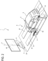
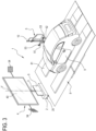
- the numeral 1 denotes a system for adjusting (that is, aligning and/or calibrating) a sensor of a vehicle 9.
- the sensor of the vehicle 9 which has to be calibrated preferably includes a front camera.
- the front camera forms part of a safety system (for example, anti-collision, lane detection, road sign recognition, or the like) of the vehicle 9.
- the system 1 comprises a base unit 2.
- the base unit 2 comprises a plurality of wheels 20.
- the wheels 20 are configured to allow the base unit 2 to move on a supporting surface.
- the system 1 comprises a support structure 3.
- the support structure 3 is connected to the base unit 2.
- the system 1 comprises a vehicle calibration assistance structure 4.
- the vehicle calibration assistance structure 4 is mounted on the support structure 3.
- the vehicle calibration assistance structure 4 is removably attached to the support structure 3. In an embodiment, the vehicle calibration assistance structure 4 is slidable along the support structure 3 in a vertical direction V (parallel to the weight force). In an embodiment, the vehicle calibration assistance structure 4 is pivotable about a horizontal axis (perpendicular to the vertical direction V). In an embodiment, the vehicle calibration assistance structure 4 is slidable along the support structure 3 in the horizontal direction.
- the support structure 3 (that is, the vehicle calibration assistance structure 4) can be moved manually to a predetermined distance from the vehicle 9.
- different vehicles 9 may require the support structure 3 (that is, the vehicle calibration assistance structure 4) to be located at different positions relative to the vehicle 9.
- at least one wheel 20 comprises a locking device configured to prevent accidental movement of the support structure 3 during use.
- the vehicle calibration assistance structure 4 includes a target panel 40.
- the target panel 40 has a surface which faces the service area 8 in which the vehicle 9 is positioned.
- the camera of the vehicle 9 sees the surface of the target panel 40.
- the surface of the target panel 40 has high contrast.
- the apparatus comprises two tracks 81 for contact with the tyres of the wheels 91 of the vehicle 9.
- the tracks 81 run parallel to each other and are oriented in a longitudinal direction.
- the tracks 81 define respective stretches 82.
- the stretches 82 of the tracks 81 are substantially aligned along a direction transverse (perpendicular) to the longitudinal direction of extension of the tracks 81 themselves.
- a floorplate configured to be surmounted by a wheel 91 of the vehicle 9 is located on at least one of the stretches 82 of the tracks 81.
- the floorplate is free to be moved along a transverse direction perpendicular to the longitudinal direction. This allows relieving stress from the wheel 91 of the vehicle 9 resting thereon.
- the target panel 40 can be positioned at a plurality of positions on the support structure 3 (depending on the height of the camera on the vehicle 9). In an embodiment, the target panel 40 comprises a blocking member configured to block it at a certain height along the support structure 3.
- the system 1 comprises a processing system.
- the processing system is configured to display an image 41 on the surface of the target panel 40.
- the image 41 provides a predetermined graphical feature.
- the graphical feature is a function of the vehicle 9 (for example, make or model).
- the processing system is operatively connected to the vehicle calibration assistance structure 4 to process data received from the vehicle calibration assistance structure 4 in order to facilitate alignment or calibration of the camera of the vehicle 9.
- the system 1 comprises a positioning device 5, configured to aid with the relative positioning between the vehicle 9 and the vehicle calibration assistance structure 4.
- the positioning device 5 is movable on wheels.
- the positioning device 5 is movable on an elongate guide which extends in longitudinal direction.
- the apparatus 1 comprises a first and a second positioning device 5 positioned on the outside of the tracks 81 on opposite sides, in proximity to, and directed towards, corresponding stretches 82 of the tracks 81.
- the first and second positioning devices are movable on respective guides.
- the positioning device 5 (or each of the positioning devices 5) comprises an optical device.
- the optical device comprises at least one camera; preferably it comprises a pair of cameras 51, 52 in a stereo configuration, oriented towards the track 81, corresponding substantially to the height of a wheel 91.
- the function of the cameras 51, 52 is to capture images of a wheel 91 positioned on a corresponding track 81 on the stretch 82 (that is, on the floorplate, if there is one) in proximity thereto.
- the cameras 51, 52 are at a distance from each other to see the wheel 91 through different optical paths.
- the optical device preferably comprises at least one matching camera 53 (or field camera).
- the positioning device 5 preferably comprises an illuminator 57 configured to generate a beam of light directed at the wheel 91 to be detected.
- the illuminator 57 comprises, for example, a plurality of LEDs or other lighting bodies.
- the positioning device 5 preferably comprises a projector element 58 adapted to project a structured light beam on the wheel 91.
- the structured light emitted by the projector element 58 is in the infrared range.
- the light emitted by the element and which strikes the wheel 91 is detected by the optical measuring system (that is, by the cameras 51, 52).
- the positioning device 5 comprises a position detector element, configured to detect the presence of a wheel 91 on the track 81 (that is, on the corresponding stretch 82 of the track 81) in proximity thereto.
- the position detector element comprises, for example, a visible light emitter and a related receiver.
- the element is capable of measuring the distance of the object struck by its own emitted light beam.
- the positioning device 5 is fixed to the floor by corresponding arms 59, at a predetermined position relative to the tracks 81.
- the arm 59 is fixed to the floor and the positioning device 5 is fixed.
- the arm 59 is slidable on an elongate track extending in the longitudinal direction and the positioning device 5 is movable on that track.
- the processing system is operatively coupled to the positioning device 5 to receive data therefrom and includes a processor programmed with instructions to process the data received from the positioning device 5 to determine measurements.
- the measurements include a spatial correlation between the vehicle calibration assistance structure 4 and the vehicle 9.
- the measurements include a spatial correlation between the target panel 40 and the at least one portion of the support structure 3.
- the measurements include a spatial correlation between the target panel 40 and the vehicle 9.
- the measurements include a spatial correlation between the target panel 40 and the camera of the vehicle 9 to be calibrated or aligned.
- the system 1 comprises a positioning target element 54 including a surface having a combination of predetermined graphical features.
- the positioning target element 54 is supported by the support structure 3.
- the positioning target element 54 is attached to the target panel 40.
- the positioning target element 54 is oriented in a forward direction towards the service area 8.
- the positioning device 5 is spaced from the support structure 3 and includes an optical device oriented in a lateral direction to see graphical features of the vehicle 9 and a matching camera 53 oriented in a backward direction towards the support structure 3, to see the positioning target element 54.
- the positioning device 5 comprises a pair of matching cameras 53 oriented in opposite directions.
- a first matching camera 53 is oriented towards the vehicle calibration assistance structure 4.
- a second matching camera 53 is oriented in the opposite direction in order to see target elements located at the back of the vehicle and/or to allow the positioning device 5 to be moved to the opposite side of the service area 8.
- the optical device preferably comprises a first camera 51 and a second camera 52.
- Precise positioning of the support structure 3 or of the target panel 40 can be performed under the guidance of the processing system as a function of the data captured by the optical device and the matching camera 53.
- the support structure 3 is placed in front of the vehicle 9, the first and second cameras 51, 52 capture images of the side of a vehicle 9 (for example, of a wheel) and the matching camera 53 captures images of the positioning target element 54; by processing these images, the processing system is able to identify the position of the support structure 3 or of the target panel 40 relative to the vehicle. If adjustments to the relative position are required, the processing system can help an operator to move the support structure 3 or the target panel 4 or the vehicle 9 to reach the correct position.
- the processing system includes an operator interface 10 configured to help the operator to reach the correct position.
- the operator interface may, for example, include a screen, a loudspeaker, a flashing light and a keyboard.
- the operator interface 10 is also configured to receive input data relating to the vehicle 9 (for example, make, model, year of manufacture, identifier code).
- Precise positioning of the support structure 3 or of the target panel 40 can be performed under the guidance of the processing system as a function of the data captured by the first and second cameras 51 and 52.
- the support structure 3 is placed in front of the vehicle 9, the first and second cameras 51, 52 capture images of the first and second sides of the vehicle 9 (for example, the front and/or rear wheels); by processing these images, the processing system is able to identify the position of the support structure 3 relative to the vehicle. If adjustments to the relative position are required, the processing system can help an operator to move the support structure 3 or the vehicle 9 to reach the correct position.
- the processing system is configured to generate the image 41 as a function of the measurements (that is, of the distance between the vehicle 9 and the vehicle calibration assistance structure 4). In an embodiment, the processing system is configured to perspectively deform the image 41 which appears on the surface of the target panel 40 as a function of the measurements. Thus, instead of, or in addition to, the operator moving the support structure 3 manually, it is possible to generate an image 41 which can be used to correct any positioning errors.
- the target panel 40 includes a screen (or monitor) and the processing system is configured to transmit to the screen a control signal representing the graphical image 41 to be displayed.
- the system 1 comprises a projector 7.
- the projector 7 is positioned above the service area 8.
- the processing system is operatively connected to the projector 7 to generate a light beam directed at the surface of the target panel 40 to generate the image 41.
- the distance between the projector 7 and the target panel 40 is known.
- the vehicle calibration assistance structure 4 includes a reflector 6.
- the reflector 6 is configured to facilitate alignment or calibration of a radar sensor of a safety system of the vehicle 9.
- the reflector 6 is mounted removably on the support structure 3 (in addition to or in place of the target panel 40).
- the reflector 6 can be positioned at a plurality of positions on the support structure 3 (in particular, at a plurality of heights).
- the reflector 6 is rotatable around the support structure 3 or around a horizontal axis (perpendicular to the vertical direction V) to correct its position according to the position of the radar sensor to be adjusted.
- the vehicle calibration assistance structure 4 includes an additional positioning target element attached to the reflector 6.
- the matching camera 53 is configured to see the additional positioning target element.
- the measurements determined by the processing system include a spatial correlation between the reflector 6 and the vehicle 9 and/or a spatial correlation between the reflector 6 and the support structure 3.
- This disclosure also relates to a method for aligning or calibrating a camera of a vehicle 9 positioned in a service area 8.
- the method comprises a step of providing a support structure 3 which supports a vehicle calibration assistance structure 4.
- the vehicle calibration assistance structure includes a target panel 40.
- the support structure 3 is positioned in such a way that the target panel 40 has one surface facing the service area 8 so that a camera of the vehicle 9 can see the surface of the target panel 40.
- the step of providing may comprise a step of adjusting the height of the target panel 40 on the support structure 3.
- the method preferably comprises a step of providing a positioning device 5.
- the method comprises a step of viewing a surface of the vehicle through an optical device included in the positioning device 5.
- the method comprises a step of viewing, with a matching camera 53, a positioning target element 54 connected to the support structure 3 (or to the vehicle calibration assistance structure 4 or to the target panel 40).
- the method preferably comprises a step of aiding with the relative positioning between the vehicle 9, located in the service area 8, and the vehicle calibration assistance structure 4 by processing data from the positioning device 5 in a processing system and determining measurements including a spatial correlation between the vehicle calibration assistance structure 4 and the vehicle 9.
- the method comprises a step of generating on the surface of the target panel 40 an image 41 having a predetermined graphical feature (for example, a particular geometric pattern).
- the graphical feature is selected by an operator based on the vehicle 9 located in the service area 8 or is chosen by the processing system as a function of input data entered by an operator (for example, vehicle make and model).
- the image 41 is generated by the processing system on the target panel 40 as a function of the measurements (thus, it may be perspectively deformed as a function of the distance between the target panel 40 and the vehicle 9 and/or of a misalignment between the target panel 40 and the vehicle 9).
- the step of generating the image 41 includes a step of transmitting a control signal representing the image 41 to be displayed to a screen (monitor) included in the target panel.
- the step of generating the image 41 includes a step of transmitting a control signal representing the image 41 to be displayed to a projector 7 configured to project the image 41 on the target panel 40.
- the method comprises a step of sending a calibration command to an electronic control unit of the vehicle 9.
- the step of sending the command is carried out by means of an instrument configured to communicate with the electronic control unit of the vehicle 9.
- the method comprises a step of viewing the image displayed on the surface of the target panel 40 through the camera of the vehicle 9 to be calibrated.
- the method comprises a step of processing data received in the processing system from the electronic control unit of the vehicle 9 (and, in one embodiment, from the vehicle calibration assistance structure 4).
Description
- This invention relates to a system for calibrating a vehicle camera and to a method for aligning or calibrating a vehicle camera. In particular, by vehicle is meant a motor car, a lorry, a truck or other wheeled vehicle.
- In particular, the field of this application is the calibration or alignment of the vehicle's sensors such as radar sensors or optical sensors (cameras) used in safety systems designed to prevent frontal collisions or in cruising speed control systems.
- In this field, it is common practice to use structures comprising a target panel bearing a graphical feature, placed in front of the vehicle and imaged by the vehicle sensor to be calibrated or aligned. For example, a system for aligning a vehicle sensor is described in patent document
WO2018/067354A1 . This system includes a support structure supporting a target panel used to align or recalibrate the vehicle's safety sensors; the support structure is movable on wheels and the target panel is movable on the support structure because it needs to be suitably positioned during the procedure for aligning or recalibrating the sensors. Positioning the target panel relative to the vehicle can be done automatically using optical devices attached to the support structure to image the vehicle; this solution is not very suitable for optimum, high-precision positioning of the support structure relative to the vehicle. - Also, as mentioned above, the target panel bears a graphical feature which the vehicle sensor "sees" during the procedure; this graphical feature is typical not only of the type of sensor to be calibrated or aligned but also of the vehicle make or model. Thus, this system requires that workshops responsible for adjusting the vehicle sensors be equipped with a large number of target panels and, each time the operator needs to adjust the sensors, the target panel suitable for the specific vehicle must be selected and mounted on the support structure. It is evident that using a system of this kind is onerous not only because it is time-consuming but also because it requires a certain amount of workshop space to store the target panels and is not really practical.
- Patent documents
WO2018/153723A1 andEP3588001A1 provide a calibration assistance system for vehicle sensors; the system comprises a screen on which an image that provides the graphical feature to be imaged by the vehicle sensor is displayed; the image is deformed as a function of the relative position between the screen and the vehicle. In fact, documentsWO2018/153723A1 andEP3588001A1 do not envisage the use of devices for assisting with the positioning of the screen and the vehicle relative to each other and positioning errors are corrected by deforming the image displayed on the screen. Thus, based on the relative position between the screen and the vehicle, the system is required to process the size of the image that is suitable for that position; this type of processing requires considerable computer power which translates as a system which is complex, expensive and not practical. -
Document DE 10 2010 062696 discloses a calibrating system for calibrating a camera of a vehicle according to the preamble ofclaim 1 and/or 13. 11 - This disclosure has for an aim to provide a calibrating system for calibrating (and/or adjusting and/or aligning) a camera (or more generally, a sensor) of a vehicle and a method for aligning or calibrating (or adjusting) a camera (or more generally, a sensor) of a vehicle in order to overcome the above mentioned drawbacks of the prior art.
- This aim is fully achieved by the system and method of
claims 1 and 13. - In particular, the system of this disclosure is a system for adjusting a sensor (or, more specifically, a camera) of a vehicle. Still more particularly, the system of this disclosure is a system for adjusting a sensor (or, more specifically, a camera) of a motor car, a lorry, a truck or other wheeled vehicle.
- According to one aspect of this disclosure, the system is a system for calibrating (or recalibrating) a vehicle sensor.
- According to one aspect of this disclosure, the system is a system for aligning (or realigning) a vehicle sensor.
- In a preferred embodiment, the sensor to be aligned or recalibrated is a camera.
- In an embodiment, the sensor to be aligned or recalibrated is a safety sensor of an ADAS (advanced driver-assistance system). In an embodiment, the sensor to be aligned or recalibrated is a radar sensor. In an embodiment, the sensor to be aligned or recalibrated is an ultrasonic sensor. In an embodiment, the sensor to be aligned or recalibrated is a LIDAR sensor.
- In an embodiment, the system comprises a base unit.
- In an embodiment, the system comprises a support structure. The support structure is connected to the base unit.
- In an embodiment, the system comprises a vehicle calibration assistance structure. The vehicle calibration assistance structure is mounted on (that is, connected to) the support structure. In an embodiment, the vehicle calibration assistance structure includes a target panel. In an embodiment, the target panel has a surface which faces the service area. The vehicle is positioned in the service area. In an embodiment, the vehicle is positioned in such a way that a camera on the vehicle can image the surface of the target panel. In an embodiment, the surface of the target panel facing towards the service area bears a first combination of predetermined graphical features.
- It should be noted that, in the context of this disclosure, the expression "combination of graphical features" is used to denote a group or set of graphical elements which can be recognized by a camera.
- In an embodiment, the system comprises a processing system. The processing system is operatively connected to the vehicle calibration assistance structure. In an embodiment, the processing system is programmed to process data received from the vehicle calibration assistance structure in order to facilitate alignment or calibration of the vehicle camera.
- The system comprises a positioning device. The positioning device is configured to aid with the relative positioning between the vehicle and the vehicle calibration assistance structure.
- In an embodiment, the positioning device is located in the service area in front of the support structure. In an embodiment, the positioning device is located on the edge of the service area. In an embodiment, the positioning device is spaced from the support structure. In an embodiment, the positioning device includes an optical device, oriented towards the service area to see graphical features of the vehicle. In an embodiment, the optical device is oriented sideways, that is, in a lateral direction, towards the vehicle. By "lateral direction" is meant a direction transverse to a forward direction (the direction from the support structure to the service area) and to a backward direction (opposite to the forward direction). In an embodiment, the positioning device includes a matching camera which is oriented towards the support structure to see a second combination of predetermined graphical features of the support structure. The matching camera is oriented in a backward direction, towards the support structure. The positioning device allows the vehicle to be positioned precisely relative to the support structure. Thus, before calibrating the sensor, the vehicle must be positioned in such a way that the sensor can see the first graphical feature from an optimum position. This position can be reached in a particularly easy and effective manner thanks to the positioning device.
- The processing system is configured to display on the surface of the target panel an image which provides the first combination of predetermined graphical features visible to the vehicle's camera. Preferably, the first combination of predetermined graphical features is a function of the vehicle. Thus, a virtual graphical feature is displayed on the surface of the target panel. In light of this, it is not necessary to change the target panel for every vehicle whose sensors must be calibrated: that is because a variety of different graphical features can be displayed on a single target panel.
- In an embodiment, the system comprises an operator interface configured to receive input data comprising one or more of the following information items regarding the vehicle: vehicle make, vehicle model, year of vehicle manufacture, vehicle identifier code. The processing system is connected to the operator interface to receive the input data therefrom and is configured to generate the image as a function of the input data. In effect, depending on the type of vehicle (make, model, year of manufacture, identifier code) a certain first graphical feature is necessary. Thus, the target panel displays an image having a combination of the predetermined graphical features based on the type of vehicle whose sensors have to be adjusted. This avoids having to replace the target panel each time a different vehicle needs to be subjected to the procedure, with evident advantages in terms of time saving and convenience of the procedure.
- In an embodiment, the processing system is operatively coupled to the positioning device to receive data therefrom and includes a processor programmed with instructions to process the data received from the positioning device to determine measurements including at least one spatial correlation between the vehicle calibration assistance structure and the vehicle.
- In an embodiment, the processing system is configured to generate the image as a function of the measurements.
- In effect, if the camera is designed to see objects from a long distance - for example, a few hundred metres away - the target panel should be positioned a long distance away from the vehicle; the use of a virtual image allows keeping the target panel a short distance away while working on the virtual image to obtain a target which is equivalent to the one that would be obtained if the panel was really a long distance away. Thus, it is possible to position the vehicle at a certain distance from the vehicle calibration assistance structure (that is, from the target panel) and to generate an image that is a function of that distance; for example, if the distance is very short, an image of reduced size is generated. In fact, vehicle manufacturers specify a predetermined distance between the target panel and the vehicle.
- In an embodiment, the processing system is configured to display on the surface of the target panel an additional image which provides the second combination of predetermined graphical features.
- In an embodiment, the processing system is configured to display the additional image on a pair of side portions of the target panel to provide the second combination of predetermined graphical features. By side portions are meant areas disposed in proximity to opposite sides of the target panel.
- In an embodiment, the processing system is configured to display the image providing the first combination of predetermined graphical features on a central portion of the target panel, interposed between the side portions of the pair of side portions. The image and the additional image are therefore displayed in distinct zones of the target panel (at different time instants or at the same time instant).
- In an embodiment, the processing system is configured to display the additional image and the image one after the other at successive times on the surface of the target panel. Thus, the image is displayed first, followed by the additional image (in different zones of the target panel or in the same zone or in overlapping zones).
- Thus, in an embodiment, the same target panel is used during a step of positioning to display the second combination of predetermined graphical features (which must be seen by the matching camera of the positioning device) and then, during a step of calibrating (with vehicle and target panel already at the optimum position), the first combination of predetermined graphical features (which must be seen by the sensor to be calibrated), in order to calibrate the sensor or camera of the vehicle.
- In an embodiment, the target panel includes a screen (or monitor or image display unit). The processing system is configured to transmit to the screen a control signal representing the graphical image to be displayed (that is, the first graphical feature and/or the second graphical feature). The use of a target panel that comprises a screen has several advantages, including high luminosity and high contrast even in brightly lit spaces.
- In an embodiment, the system includes a projector. The processing system is operatively connected to the projector to generate a light beam directed at the surface of the target panel to generate the image.
- In an embodiment, the position of the projector relative to the target panel is predetermined. In an embodiment, the image projected on the target panel depends on the relative position between the projector and the target panel.
- In an embodiment, the processing system is configured to transmit to the projector a control signal representing the graphical image to be displayed (that is, the first graphical feature and/or the second graphical feature). The use of a target panel on which to project the image offers advantages in terms of limited costs and high flexibility in defining the size of the image.
- In an embodiment, the vehicle calibration assistance structure comprises a positioning target element. The positioning target element includes a surface bearing the second combination of predetermined graphical features. The positioning target element is supported by the support structure and is oriented towards the service area.
- In an embodiment, the position of the positioning target element relative to the target panel, and hence relative to the first combination of graphical features, is predetermined. In an embodiment, the position of the positioning target element relative to the target panel is determined by a step of calibrating the calibration assistance structure. In an embodiment, this calibration is performed using a camera - for example, the matching camera - which simultaneously displays the position of the calibrating target and the first combination of graphical features.
- In an embodiment, the positioning target element is oriented in a forward direction, towards the service area. In the context of this disclosure, it should be noted that "forward direction" means the direction from the support structure to the service area. By "backward direction" is meant, vice versa, the direction from the service area to the support structure (opposite to the "forward" direction).
- In an embodiment, the calibration assistance structure comprises a pair of positioning target elements, supported by the support structure and protruding from respective opposite sides of the target panel. In an embodiment, the positioning target elements of this pair are fixed to opposite sides of the target panel.
- In an embodiment, the positioning target element (or positioning target elements) is attached to the target panel. Thus, the second combination of predetermined graphical features may be displayed on the target panel itself or it may appear on a positioning target element (or a pair of positioning target elements) connected to the support structure; these two solutions might also coexist in the same system, allowing the operator to choose whether to perform positioning by displaying the second graphical feature on the target panel or using the positioning target element.
- In an embodiment, the optical device comprises at least one camera.
- Preferably, the optical device comprises a pair of cameras in a stereo configuration. The cameras of this pair are configured to see graphical features of the vehicle; for example, of the wheel.
- In an embodiment, the processing system is configured to generate a plurality of images in sequence. In effect, some alignment/calibration procedures require the vehicle to be moved between a plurality of static positions; according to an aspect of this disclosure, therefore, the vehicle is not really moved from one position to another but instead, a plurality of images are generated in succession.
- In an embodiment, the vehicle calibration assistance structure, which is supported by the support structure, includes a reflector. In an embodiment, the reflector includes a metallic surface. In an embodiment, the reflector is configured to reflect electromagnetic waves. In an embodiment, the reflector is configured to facilitate alignment or calibration of a radar sensor of a vehicle safety system.
- In an embodiment, the reflector is movable relative to the support structure. In an embodiment, the support structure is configured to vary the distance of the reflector from an axis of the vehicle. In an embodiment, the support structure is configured to vary the inclination of the reflector.
- In an embodiment, the vehicle calibration assistance structure includes a calibrating unit (e.g., a target panel) for the vehicle's night vision systems (for example, infrared sensors).
- In an embodiment, the reflector is removably connected to the vehicle calibration assistance structure (that is, to the support structure).
- In an embodiment, the target panel along at least one portion of the support structure. In an embodiment, the target panel is slidable along the at least one portion of the support structure in a vertical direction (parallel to the weight force).
- In an embodiment, the base unit includes a plurality di wheels, configured to allow the base unit to be moved on the flat surface (preferably horizontal) which supports it.
- Thus, in an embodiment, the target panel is movable in a horizontal plane as one with the base unit and with the support structure and in the vertical direction, thanks to its sliding in the vertical direction.
- In an embodiment, the support structure is configured to vary the inclination of the target panel.
- In an embodiment, the processing system is programmed to determine measurements including at least one correlation between the target panel and the at least one portion of the support structure (for example, the height at which the target panel is mounted on the support structure).
- In an embodiment, the vehicle calibration assistance structure includes an optical projection system including at least one laser emitter (projector). In an embodiment, the processing system is operatively coupled to the optical projection system to activate the laser emitter to project a ray onto a surface in proximity to the system or adjusting the sensor of a vehicle. In an embodiment, the processing system is connected to the optical projection system to determine a distance between the laser projector and the surface on which the laser ray is projected (which may be a surface of the vehicle). The optical projection system is useful, in particular, for prepositioning the calibration assistance structure relative to a predetermined point or to an axis of the vehicle (for example, axis of symmetry or thrust axis) according to the manufacturer's specifications.
- In an embodiment, the vehicle calibration assistance structure includes a distance measuring system. In one embodiment, the distance measuring system is an optical (laser) system. In another embodiment, the distance measuring system is an ultrasonic system.
- The distance measuring system is useful, in particular, for prepositioning the calibration assistance structure at a predetermined, factory-set distance from the vehicle.
- This disclosure also provides a method for aligning or calibrating a camera (or more generally, a sensor) of a vehicle positioned in a service area. More generally speaking, the method of this description is a method for adjusting a sensor of a vehicle.
- In an embodiment, the method comprises a step of providing a support structure which supports a vehicle calibration assistance structure. The vehicle calibration assistance structure includes a target panel having a surface which faces the service area so that a camera of the vehicle can see the surface of the target panel. In an embodiment, the surface of the target panel bears a first combination of predetermined graphical features. In an embodiment, during the step of providing, the calibration assistance structure is pre-positioned at a position specified by the vehicle manufacturer. In an embodiment, the calibration assistance structure is prepositioned relative to the vehicle with the aid of a distance measuring system and/or a laser projector.
- In an embodiment, the method comprises a step of sending a calibration command to an electronic control unit of the vehicle.
- In an embodiment, the method comprises a step of viewing the image displayed on the target panel through the vehicle camera to be calibrated. The step of viewing is started by the calibration command. In an embodiment, once the camera has viewed the image, the electronic control unit sends response data to the processing system. In an embodiment, the response data relate to the outcome of the calibration command. In an embodiment, the response data contain instructions for fine tuning or adjusting the position.
- In an embodiment, the method comprises a step of processing data received in the processing system from the calibration assistance structure and from the control unit of the vehicle.
- In an embodiment, the method comprises a step of providing a positioning device.
- The positioning device includes an optical device, oriented towards the service area to see graphical features of the vehicle. Preferably, the graphical features of the vehicle comprise features relating to the wheels of the vehicle. The optical device is oriented in a lateral direction. In an embodiment, the positioning device also includes a matching camera which is oriented towards the support structure. The matching camera is oriented in a backward direction.
- The method comprises a step of aiding with the relative positioning between the vehicle positioned in the service area and the vehicle calibration assistance structure. Preferably, the step of aiding with the positioning includes viewing the graphical features of the vehicle through the optical device. Preferably, the step of aiding with the positioning includes viewing a second combination of predetermined graphical features of the support structure through the matching camera.
- Thanks to the step of aiding with the positioning performed with the positioning device, the vehicle and the calibration assistance structure are positioned very precisely relative to each other.
- In an embodiment, the method comprises a step of displaying (that is, generating) on the surface of the target panel an image having a predetermined graphical feature visible to the camera of the vehicle.
- In an embodiment, the method comprises a step of displaying (that is, generating) on the surface of the target panel an additional image having a second combination of predetermined graphical features visible to the matching camera of the positioning device. The step of generating the additional image is preferably part of the step of positioning. Thus, the additional image is generated on the target panel during the step of positioning, and after that, the image seen by the camera during the step of viewing is generated.
- In an embodiment, the step of aiding with the positioning comprises viewing through the matching camera a positioning target element bearing a second combination of predetermined graphical features. The second graphical feature is displayed on the support structure.
- The method comprises a step of generating on the surface of the target panel an image representing the first combination of predetermined graphical features visible to the camera of the vehicle.
- In an embodiment, the target panel includes a screen to which the processing system, during the step of displaying, transmits a control signal representing the image to be displayed.
- In an embodiment, the image is projected on the target panel by a projector to which the processing system transmits a control signal representing the image to be displayed.
- In an embodiment, the method comprises a step of generating on the surface of the target panel an additional image having a second combination of predetermined graphical features visible to the matching camera of the positioning device.
- In an embodiment, the second graphical feature is displayed on a positioning target element (or a pair of positioning target elements) connected to the target panel.
- In an embodiment, the step of aiding with the positioning includes processing data received from the positioning device in a processing system. In an embodiment, the step of aiding with the positioning includes a step of determining measurements which include at least one spatial correlation between the vehicle calibration assistance structure and the vehicle.
- In an embodiment, the image is generated by the processing system as a function of the measurements.
- These and other features are more apparent from the following description of a preferred embodiment, illustrated by way of non-limiting example in the accompanying drawings, in which:
-
Figure 1 shows a vehicle positioned in a service area and a possible embodiment of an adjustment system according to this disclosure; -
Figure 1A shows the positioning device ofFigure 1 ; -
Figures 2 ,3 ,4 ,5 show the vehicle and the adjustment system ofFigure 1 in respective embodiments; -
Figure 3A shows the positioning device ofFigure 3 ;
.Figures 6A, 6B and 6C show respective images displayed on the target panel of the system of any one ofFigures 1 ,2 ,3 ,4 ,5 . - With reference to this disclosure, the
numeral 1 denotes a system for adjusting (that is, aligning and/or calibrating) a sensor of avehicle 9. - The sensor of the
vehicle 9 which has to be calibrated preferably includes a front camera. In an embodiment, the front camera forms part of a safety system (for example, anti-collision, lane detection, road sign recognition, or the like) of thevehicle 9. - The
system 1 comprises abase unit 2. Thebase unit 2 comprises a plurality ofwheels 20. Thewheels 20 are configured to allow thebase unit 2 to move on a supporting surface. - The
system 1 comprises asupport structure 3. Thesupport structure 3 is connected to thebase unit 2. - The
system 1 comprises a vehiclecalibration assistance structure 4. The vehiclecalibration assistance structure 4 is mounted on thesupport structure 3. - In an embodiment, the vehicle
calibration assistance structure 4 is removably attached to thesupport structure 3. In an embodiment, the vehiclecalibration assistance structure 4 is slidable along thesupport structure 3 in a vertical direction V (parallel to the weight force). In an embodiment, the vehiclecalibration assistance structure 4 is pivotable about a horizontal axis (perpendicular to the vertical direction V). In an embodiment, the vehiclecalibration assistance structure 4 is slidable along thesupport structure 3 in the horizontal direction. - Thanks to the
wheels 20 of thebase unit 2, the support structure 3 (that is, the vehicle calibration assistance structure 4) can be moved manually to a predetermined distance from thevehicle 9. In effect,different vehicles 9 may require the support structure 3 (that is, the vehicle calibration assistance structure 4) to be located at different positions relative to thevehicle 9. In an embodiment, at least onewheel 20 comprises a locking device configured to prevent accidental movement of thesupport structure 3 during use. - In an embodiment, the vehicle
calibration assistance structure 4 includes atarget panel 40. Thetarget panel 40 has a surface which faces theservice area 8 in which thevehicle 9 is positioned. The camera of thevehicle 9 sees the surface of thetarget panel 40. In an embodiment, the surface of thetarget panel 40 has high contrast. - The apparatus comprises two
tracks 81 for contact with the tyres of thewheels 91 of thevehicle 9. Thetracks 81 run parallel to each other and are oriented in a longitudinal direction. - The
tracks 81 define respective stretches 82. The stretches 82 of thetracks 81 are substantially aligned along a direction transverse (perpendicular) to the longitudinal direction of extension of thetracks 81 themselves. - Preferably (but not necessarily) a floorplate configured to be surmounted by a
wheel 91 of thevehicle 9 is located on at least one of thestretches 82 of thetracks 81. - Preferably, the floorplate is free to be moved along a transverse direction perpendicular to the longitudinal direction. This allows relieving stress from the
wheel 91 of thevehicle 9 resting thereon. - In an embodiment, the
target panel 40 can be positioned at a plurality of positions on the support structure 3 (depending on the height of the camera on the vehicle 9). In an embodiment, thetarget panel 40 comprises a blocking member configured to block it at a certain height along thesupport structure 3. - The
system 1 comprises a processing system. In an embodiment, the processing system is configured to display animage 41 on the surface of thetarget panel 40. Theimage 41 provides a predetermined graphical feature. The graphical feature is a function of the vehicle 9 (for example, make or model). - In an embodiment, the processing system is operatively connected to the vehicle
calibration assistance structure 4 to process data received from the vehiclecalibration assistance structure 4 in order to facilitate alignment or calibration of the camera of thevehicle 9. - More specifically, in an embodiment, the
system 1 comprises apositioning device 5, configured to aid with the relative positioning between thevehicle 9 and the vehiclecalibration assistance structure 4. In an embodiment, thepositioning device 5 is movable on wheels. In an embodiment, thepositioning device 5 is movable on an elongate guide which extends in longitudinal direction. - In an embodiment, the
apparatus 1 comprises a first and asecond positioning device 5 positioned on the outside of thetracks 81 on opposite sides, in proximity to, and directed towards, corresponding stretches 82 of thetracks 81. In an embodiment, the first and second positioning devices are movable on respective guides. - Preferably, the positioning device 5 (or each of the positioning devices 5) comprises an optical device.
- The optical device comprises at least one camera; preferably it comprises a pair of
cameras track 81, corresponding substantially to the height of awheel 91. - The function of the
cameras wheel 91 positioned on acorresponding track 81 on the stretch 82 (that is, on the floorplate, if there is one) in proximity thereto. Thecameras wheel 91 through different optical paths. - Further, the optical device preferably comprises at least one matching camera 53 (or field camera).
- Further, the
positioning device 5 preferably comprises anilluminator 57 configured to generate a beam of light directed at thewheel 91 to be detected. - The
illuminator 57 comprises, for example, a plurality of LEDs or other lighting bodies. - Further, the
positioning device 5 preferably comprises aprojector element 58 adapted to project a structured light beam on thewheel 91. Preferably, the structured light emitted by theprojector element 58 is in the infrared range. Still more preferably, the light emitted by the element and which strikes thewheel 91 is detected by the optical measuring system (that is, by thecameras 51, 52). - In an embodiment, the
positioning device 5 comprises a position detector element, configured to detect the presence of awheel 91 on the track 81 (that is, on the correspondingstretch 82 of the track 81) in proximity thereto. - The position detector element comprises, for example, a visible light emitter and a related receiver. Preferably, the element is capable of measuring the distance of the object struck by its own emitted light beam. It should be noted that in an embodiment, the
positioning device 5 is fixed to the floor by correspondingarms 59, at a predetermined position relative to thetracks 81. In an embodiment, thearm 59 is fixed to the floor and thepositioning device 5 is fixed. In an embodiment, thearm 59 is slidable on an elongate track extending in the longitudinal direction and thepositioning device 5 is movable on that track. - The processing system is operatively coupled to the
positioning device 5 to receive data therefrom and includes a processor programmed with instructions to process the data received from thepositioning device 5 to determine measurements. In an embodiment, the measurements include a spatial correlation between the vehiclecalibration assistance structure 4 and thevehicle 9. In an embodiment, the measurements include a spatial correlation between thetarget panel 40 and the at least one portion of thesupport structure 3. In an embodiment, the measurements include a spatial correlation between thetarget panel 40 and thevehicle 9. In an embodiment, the measurements include a spatial correlation between thetarget panel 40 and the camera of thevehicle 9 to be calibrated or aligned. In an embodiment, thesystem 1 comprises apositioning target element 54 including a surface having a combination of predetermined graphical features. Thepositioning target element 54 is supported by thesupport structure 3. Thepositioning target element 54 is attached to thetarget panel 40. Thepositioning target element 54 is oriented in a forward direction towards theservice area 8. - In an embodiment, the
positioning device 5 is spaced from thesupport structure 3 and includes an optical device oriented in a lateral direction to see graphical features of thevehicle 9 and a matchingcamera 53 oriented in a backward direction towards thesupport structure 3, to see thepositioning target element 54. In an embodiment, thepositioning device 5 comprises a pair of matchingcameras 53 oriented in opposite directions. Afirst matching camera 53 is oriented towards the vehiclecalibration assistance structure 4. Asecond matching camera 53 is oriented in the opposite direction in order to see target elements located at the back of the vehicle and/or to allow thepositioning device 5 to be moved to the opposite side of theservice area 8. - The optical device preferably comprises a
first camera 51 and asecond camera 52. - Precise positioning of the
support structure 3 or of thetarget panel 40 can be performed under the guidance of the processing system as a function of the data captured by the optical device and the matchingcamera 53. For example, thesupport structure 3 is placed in front of thevehicle 9, the first andsecond cameras camera 53 captures images of thepositioning target element 54; by processing these images, the processing system is able to identify the position of thesupport structure 3 or of thetarget panel 40 relative to the vehicle. If adjustments to the relative position are required, the processing system can help an operator to move thesupport structure 3 or thetarget panel 4 or thevehicle 9 to reach the correct position. In an embodiment, the processing system includes anoperator interface 10 configured to help the operator to reach the correct position. The operator interface may, for example, include a screen, a loudspeaker, a flashing light and a keyboard. - Preferably, the
operator interface 10 is also configured to receive input data relating to the vehicle 9 (for example, make, model, year of manufacture, identifier code). - Precise positioning of the
support structure 3 or of thetarget panel 40 can be performed under the guidance of the processing system as a function of the data captured by the first andsecond cameras support structure 3 is placed in front of thevehicle 9, the first andsecond cameras support structure 3 relative to the vehicle. If adjustments to the relative position are required, the processing system can help an operator to move thesupport structure 3 or thevehicle 9 to reach the correct position. - In an embodiment, the processing system is configured to generate the
image 41 as a function of the measurements (that is, of the distance between thevehicle 9 and the vehicle calibration assistance structure 4). In an embodiment, the processing system is configured to perspectively deform theimage 41 which appears on the surface of thetarget panel 40 as a function of the measurements. Thus, instead of, or in addition to, the operator moving thesupport structure 3 manually, it is possible to generate animage 41 which can be used to correct any positioning errors. In an embodiment, thetarget panel 40 includes a screen (or monitor) and the processing system is configured to transmit to the screen a control signal representing thegraphical image 41 to be displayed. - In an embodiment, the
system 1 comprises aprojector 7. In an embodiment, theprojector 7 is positioned above theservice area 8. In an embodiment, the processing system is operatively connected to theprojector 7 to generate a light beam directed at the surface of thetarget panel 40 to generate theimage 41. Preferably, the distance between theprojector 7 and thetarget panel 40 is known. - In an embodiment, the vehicle
calibration assistance structure 4 includes areflector 6. Thereflector 6 is configured to facilitate alignment or calibration of a radar sensor of a safety system of thevehicle 9. In an embodiment, thereflector 6 is mounted removably on the support structure 3 (in addition to or in place of the target panel 40). In an embodiment, thereflector 6 can be positioned at a plurality of positions on the support structure 3 (in particular, at a plurality of heights). In an embodiment, thereflector 6 is rotatable around thesupport structure 3 or around a horizontal axis (perpendicular to the vertical direction V) to correct its position according to the position of the radar sensor to be adjusted. - In an embodiment, the vehicle
calibration assistance structure 4 includes an additional positioning target element attached to thereflector 6. In an embodiment, the matchingcamera 53 is configured to see the additional positioning target element. In an embodiment, the measurements determined by the processing system include a spatial correlation between thereflector 6 and thevehicle 9 and/or a spatial correlation between thereflector 6 and thesupport structure 3. - This disclosure also relates to a method for aligning or calibrating a camera of a
vehicle 9 positioned in aservice area 8. - The method comprises a step of providing a
support structure 3 which supports a vehiclecalibration assistance structure 4. The vehicle calibration assistance structure includes atarget panel 40. Thesupport structure 3 is positioned in such a way that thetarget panel 40 has one surface facing theservice area 8 so that a camera of thevehicle 9 can see the surface of thetarget panel 40. The step of providing may comprise a step of adjusting the height of thetarget panel 40 on thesupport structure 3. - The method preferably comprises a step of providing a
positioning device 5. The method comprises a step of viewing a surface of the vehicle through an optical device included in thepositioning device 5. In an embodiment, the method comprises a step of viewing, with a matchingcamera 53, apositioning target element 54 connected to the support structure 3 (or to the vehiclecalibration assistance structure 4 or to the target panel 40). - The method preferably comprises a step of aiding with the relative positioning between the
vehicle 9, located in theservice area 8, and the vehiclecalibration assistance structure 4 by processing data from thepositioning device 5 in a processing system and determining measurements including a spatial correlation between the vehiclecalibration assistance structure 4 and thevehicle 9. - The method comprises a step of generating on the surface of the
target panel 40 animage 41 having a predetermined graphical feature (for example, a particular geometric pattern). The graphical feature is selected by an operator based on thevehicle 9 located in theservice area 8 or is chosen by the processing system as a function of input data entered by an operator (for example, vehicle make and model). In an embodiment, theimage 41 is generated by the processing system on thetarget panel 40 as a function of the measurements (thus, it may be perspectively deformed as a function of the distance between thetarget panel 40 and thevehicle 9 and/or of a misalignment between thetarget panel 40 and the vehicle 9). In an embodiment, the step of generating theimage 41 includes a step of transmitting a control signal representing theimage 41 to be displayed to a screen (monitor) included in the target panel. - In an embodiment, the step of generating the
image 41 includes a step of transmitting a control signal representing theimage 41 to be displayed to aprojector 7 configured to project theimage 41 on thetarget panel 40. - The method comprises a step of sending a calibration command to an electronic control unit of the
vehicle 9. Preferably, the step of sending the command is carried out by means of an instrument configured to communicate with the electronic control unit of thevehicle 9. - The method comprises a step of viewing the image displayed on the surface of the
target panel 40 through the camera of thevehicle 9 to be calibrated. - The method comprises a step of processing data received in the processing system from the electronic control unit of the vehicle 9 (and, in one embodiment, from the vehicle calibration assistance structure 4).
- It should be noted that what is described above with reference to the front of the vehicle (and the related sensors and/or cameras) also applies, with the necessary changes made, to the back and sides of the vehicle.
Claims (15)
- A calibrating system (1) for calibrating a camera of a vehicle (9), the system (1) comprising:- a base unit (2);- a support structure (3) connected to the base unit (2);- a vehicle calibration assistance structure (4) mounted on the support structure (3) and including a target panel (40), which has a surface facing forward towards a service area (8), wherein the surface of the target panel (40) bears a first combination of predetermined graphical features, the vehicle (9) being positioned in the service area (8) so that the camera of the vehicle (9) can see the surface of the target panel (40);- a processing system, operatively connected the vehicle calibration assistance structure (4) to process data received from the vehicle calibration assistance structure (4) in order to facilitate alignment or calibration of the camera of the vehicle (9);- a positioning device (5), configured to aid a relative positioning between the vehicle (9) and the vehicle calibration assistance structure (4),characterized in that the processing system is configured to display on the surface of the target panel (40) an image (41) which provides the first combination of predetermined graphical features visible to the camera of the vehicle (9).
- The system (1) according to claim 1, comprising an operator interface (10) configured to receive input data comprising one or more of the following information items regarding the vehicle (9): make of the vehicle (9), model of the vehicle (9), year of manufacture of the vehicle (9), identifier code of the vehicle (9); and wherein the processing system is connected to the operator interface to receive the input data therefrom and is configured to generate the image (41) as a function of the input data.
- The system (1) according to any of the previous claims, wherein the processing system is operatively coupled to the positioning device (5) to receive data therefrom and includes a processor programmed with instructions to process the data received from the positioning device (5) to determine measurements including at least one spatial correlation between the vehicle calibration assistance structure (4) and the vehicle (9).
- The system (1) according to any one of the previous claims, wherein the processing system is configured to display on the surface of the target panel (40) an additional image which provides a second combination of predetermined graphical features.
- The system (1) according to claim 4, wherein one of the following conditions is met:i) the processing system is configured to display the additional image on a pair of side portions of the target panel (40), to provide the second combination of predetermined graphical features;ii) the processing system is configured to display the image providing the first combination of graphical features on a central portion of the target panel (40), interposed between the side portions of the pair of side portions;iii) the processing system is configured to display the additional image and the image one after the other at successive times on the surface of the target panel (40).
- The system (1) according to any one of the preceding claims, wherein either of the following conditions is met:i) the target panel (40) includes a screen and the processing system is configured to transmit to the screen a control signal representing the graphical image (41) to be displayed:ii) the system (1) further comprises a projector (7), wherein the processing system is operatively connected to the projector (7) to generate a light beam directed at the surface of the target panel (40) to generate the image (41).
- The system (1) according to claim 6, wherein the calibration assistance structure (4) comprises a pair of positioning target elements (54), supported by the support structure (3) and protruding from respective opposite sides of the target panel (40).
- The system (1) according to any one of the preceding claims, wherein the vehicle calibration assistance structure (4) includes a reflector and is supported by the support structure.
- The system (1) according claim 8, wherein the reflector is movable relative to the support structure, wherein the support structure is configured to vary a distance of the reflector from an axis of the vehicle and/or to vary an inclination of the reflector.
- The system (1) according to any one of the preceding claims, wherein the vehicle calibration assistance structure (4) includes an optical projection system including at least one laser emitter.
- The system (1) according claim 10, wherein the processing system is connected to the optical projection system to determine a distance between the laser projector and a surface on which the laser ray is projected.
- The system (1) according to any one of the preceding claims, wherein the vehicle calibration assistance structure (4) includes a distance measuring system, wherein the distance measuring system is either optical or ultrasonic system.
- A method for aligning or calibrating a camera of a vehicle (9) positioned in a service area (8), the method comprising the following steps:- providing a support structure (3) which supports a vehicle calibration assistance structure (4), the vehicle calibration assistance structure (4) including a target panel (40), which has a surface facing forward towards a service area (8), wherein the surface of the target panel (40) bears a first combination of predetermined graphical features, the vehicle (9) being positioned in the service area (8) so that the camera of the vehicle (9) can see the surface of the target panel (40);- sending a calibration command to an electronic control unit of the vehicle (9);- viewing the image displayed on the surface of the target panel (40) through the camera of the vehicle (9) to be calibrated;- processing data received in a processing system from the calibration assistance structure (4) and from the electronic control unit of the vehicle (9);- providing a positioning device (5);- aiding with the relative positioning between the vehicle (9), positioned in the service area (8), and the vehicle calibration assistance structure (4),characterized in that the method further comprises a step of generating on the surface of the target panel (40) an image (41) representing the first combination of predetermined graphical features visible to the camera of the vehicle.
- The method according to claim 13, comprising a step of generating on the surface of the target panel (40) an additional image having a second combination of predetermined graphical features visible to the matching camera (53) of the positioning device (5), wherein the additional image and the image (41) are generated in different zones and/or at different time instants.
- The method according to claim 13 or 14, wherein the vehicle calibration assistance structure (4) includes one or more of the following items:i) a reflector;ii) an optical projection system including at least one laser emitter;iii) distance measuring system.
Priority Applications (1)
| Application Number | Priority Date | Filing Date | Title |
|---|---|---|---|
| EP23194804.3A EP4273004A3 (en) | 2018-09-28 | 2019-05-07 | System for calibrating a vehicle camera |
Applications Claiming Priority (2)
| Application Number | Priority Date | Filing Date | Title |
|---|---|---|---|
| IT201800009030 | 2018-09-28 | ||
| EP19173043.1A EP3629053B1 (en) | 2018-09-28 | 2019-05-07 | System for calibrating a vehicle camera |
Related Parent Applications (2)
| Application Number | Title | Priority Date | Filing Date |
|---|---|---|---|
| EP19173043.1A Division EP3629053B1 (en) | 2018-09-28 | 2019-05-07 | System for calibrating a vehicle camera |
| EP19173043.1A Division-Into EP3629053B1 (en) | 2018-09-28 | 2019-05-07 | System for calibrating a vehicle camera |
Related Child Applications (1)
| Application Number | Title | Priority Date | Filing Date |
|---|---|---|---|
| EP23194804.3A Division EP4273004A3 (en) | 2018-09-28 | 2019-05-07 | System for calibrating a vehicle camera |
Publications (2)
| Publication Number | Publication Date |
|---|---|
| EP3742192A1 EP3742192A1 (en) | 2020-11-25 |
| EP3742192B1 true EP3742192B1 (en) | 2023-09-06 |
Family
ID=64557086
Family Applications (3)
| Application Number | Title | Priority Date | Filing Date |
|---|---|---|---|
| EP20184929.6A Active EP3742192B1 (en) | 2018-09-28 | 2019-05-07 | System for calibrating a vehicle camera |
| EP19173043.1A Active EP3629053B1 (en) | 2018-09-28 | 2019-05-07 | System for calibrating a vehicle camera |
| EP23194804.3A Pending EP4273004A3 (en) | 2018-09-28 | 2019-05-07 | System for calibrating a vehicle camera |
Family Applications After (2)
| Application Number | Title | Priority Date | Filing Date |
|---|---|---|---|
| EP19173043.1A Active EP3629053B1 (en) | 2018-09-28 | 2019-05-07 | System for calibrating a vehicle camera |
| EP23194804.3A Pending EP4273004A3 (en) | 2018-09-28 | 2019-05-07 | System for calibrating a vehicle camera |
Country Status (4)
| Country | Link |
|---|---|
| US (1) | US11836947B2 (en) |
| EP (3) | EP3742192B1 (en) |
| CN (1) | CN110967194A (en) |
| ES (1) | ES2842999T3 (en) |
Families Citing this family (15)
| Publication number | Priority date | Publication date | Assignee | Title |
|---|---|---|---|---|
| HU4982U (en) * | 2017-07-05 | 2019-05-28 | Aimotive Kft | Support structure |
| US10989624B2 (en) * | 2018-09-28 | 2021-04-27 | Nexion S.P.A. | Vehicle headlight measurement system instrumentation structure |
| IT201800010372A1 (en) * | 2018-11-15 | 2020-05-15 | Nexion Spa | HEADLIGHT TEST SYSTEM FOR A VEHICLE. |
| IT201900001167A1 (en) | 2019-01-25 | 2020-07-25 | Nexion Spa | APPARATUS FOR CALIBRATING A SENSOR OF AN ADVANCED ASSISTANCE SYSTEM DRIVING A VEHICLE |
| EP3966520A1 (en) * | 2019-05-08 | 2022-03-16 | NEXION S.p.A. | Method, computer program and apparatus for calibrating an adas sensor of an advanced driver assistance system of a vehicle |
| DE102020108872A1 (en) | 2020-03-31 | 2021-09-30 | Beissbarth Gmbh | CALIBRATION BOARD AND CALIBRATION DEVICE FOR VEHICLE ENVIRONMENTAL SENSORS |
| EP3929619A1 (en) * | 2020-06-22 | 2021-12-29 | Mahle International GmbH | A method of calibration of a front optical sensor mounted on board of a vehicle |
| USD977351S1 (en) * | 2020-09-11 | 2023-02-07 | Autel Intelligent Technology Corp., Ltd. | Vehicle calibrating and aligning apparatus |
| US11172193B1 (en) * | 2020-12-04 | 2021-11-09 | Argo AI, LLC | Method and system to calibrate camera devices of a vehicle vision system using a programmable calibration target device |
| IT202100004388A1 (en) | 2021-02-25 | 2022-08-25 | Texa Spa | VEHICLE SERVICE SYSTEM AND ITS METHOD OF OPERATION |
| DE102021201923A1 (en) | 2021-03-01 | 2022-09-01 | Robert Bosch Gesellschaft mit beschränkter Haftung | Method and system for calibrating at least one vehicle sensor arranged in a vehicle |
| IT202100018683A1 (en) | 2021-07-15 | 2023-01-15 | Nexion Spa | EQUIPMENT TO SERVICE A VEHICLE AND METHOD OF PERFORMING SERVICE ON A VEHICLE |
| CN113484833A (en) * | 2021-07-29 | 2021-10-08 | 深圳市道通科技股份有限公司 | Automobile calibration equipment |
| US11933911B2 (en) * | 2021-08-19 | 2024-03-19 | Aptiv Technologies AG | Radar system calibration with bistatic sidelobe compensation |
| CN116698447B (en) * | 2023-08-04 | 2023-10-20 | 安徽中科星驰自动驾驶技术有限公司 | Calibration device of double-target type automatic driving auxiliary system |
Citations (5)
| Publication number | Priority date | Publication date | Assignee | Title |
|---|---|---|---|---|
| EP2172873A2 (en) * | 2008-10-06 | 2010-04-07 | Mobileye Vision Technologies | Bundling of driver assistance systems |
| WO2011085489A1 (en) * | 2010-01-13 | 2011-07-21 | Magna Electronics Inc. | Vehicular camera and method for periodic calibration of vehicular camera |
| US20170024889A1 (en) * | 2015-07-23 | 2017-01-26 | International Business Machines Corporation | Self-calibration of a static camera from vehicle information |
| WO2017130823A1 (en) * | 2016-01-29 | 2017-08-03 | パナソニックIpマネジメント株式会社 | Camera calibration device and camera calibration method |
| CN109285120A (en) * | 2018-11-21 | 2019-01-29 | 北京汽车研究总院有限公司 | A kind of image mosaic, image calibration method, vehicle and calibration facility |
Family Cites Families (27)
| Publication number | Priority date | Publication date | Assignee | Title |
|---|---|---|---|---|
| US6823601B2 (en) * | 2002-09-17 | 2004-11-30 | Snap-On Incorporated | Apparatus for use with a 3D image wheel aligner for facilitating adjustment of an adaptive cruise control sensor on a motor vehicle |
| EP1623185B1 (en) * | 2003-05-09 | 2010-08-11 | Snap-on Incorporated | Camera technique for adaptive cruise control (acc) sensor adjustment |
| US7382913B2 (en) * | 2003-08-22 | 2008-06-03 | Hunter Engineering Company | Method and apparatus for guiding placement of vehicle service fixtures |
| US7424387B1 (en) * | 2007-04-18 | 2008-09-09 | Snap-On Incorporated | Method for use with an optical aligner system for positioning a fixture relative to a vehicle |
| US9459515B2 (en) * | 2008-12-05 | 2016-10-04 | Mobileye Vision Technologies Ltd. | Adjustable camera mount for a vehicle windshield |
| DE102009001742A1 (en) * | 2009-03-23 | 2010-09-30 | Robert Bosch Gmbh | Method and device for determining the position and orientation of a driver assistance system camera of a vehicle to the vehicle |
| JP5091902B2 (en) * | 2009-03-31 | 2012-12-05 | アイシン精機株式会社 | Calibration index used for calibration of in-vehicle camera, in-vehicle camera calibration method and system using the calibration index, and program for the system |
| IT1395807B1 (en) * | 2009-09-25 | 2012-10-26 | Corghi Spa | APPARATUS AND PROCEDURE FOR VERIFICATION OF THE STRUCTURE OF A VEHICLE. |
| DE102010062696A1 (en) * | 2010-12-09 | 2012-06-14 | Robert Bosch Gmbh | Method and device for calibrating and adjusting a vehicle environment sensor. |
| US9170101B2 (en) * | 2011-10-28 | 2015-10-27 | Hunter Engineering Company | Method and apparatus for positioning a vehicle service device relative to a vehicle thrust line |
| KR101510336B1 (en) * | 2013-11-14 | 2015-04-07 | 현대자동차 주식회사 | Device for inspecting driver assistance system of vehicle |
| KR101510338B1 (en) * | 2013-11-22 | 2015-04-07 | 현대자동차 주식회사 | Device for inspecting lane departure warning system of vehicle |
| ITBO20130697A1 (en) | 2013-12-19 | 2015-06-20 | Corghi Spa | APPARATUS AND DIAGNOSTIC ASSESSMENT METHOD OF A VEHICLE STRUCTURE |
| JP6427900B2 (en) * | 2014-03-07 | 2018-11-28 | 株式会社リコー | Calibration method, calibration system, program, and moving object |
| US9933515B2 (en) * | 2014-12-09 | 2018-04-03 | Toyota Motor Engineering & Manufacturing North America, Inc. | Sensor calibration for autonomous vehicles |
| KR102386670B1 (en) * | 2015-07-08 | 2022-04-14 | 엘지이노텍 주식회사 | Self calibration apparatus of automotive radar and method having the same |
| DE102015118874A1 (en) * | 2015-11-04 | 2017-05-04 | Valeo Schalter Und Sensoren Gmbh | Method for operating a sensor system of a motor vehicle, driver assistance system and system for calibrating a sensor system of a motor vehicle |
| EP3708949A1 (en) * | 2016-10-04 | 2020-09-16 | Hunter Engineering Company | Vehicle measurement system instrumentation structure and method |
| US10788400B2 (en) * | 2016-10-11 | 2020-09-29 | Hunter Engineering Company | Method and apparatus for vehicle inspection and safety system calibration using projected images |
| DE102017203155A1 (en) | 2017-02-27 | 2018-08-30 | Robert Bosch Gmbh | Apparatus and method for calibrating vehicle assistance systems |
| DE212018000382U1 (en) * | 2017-12-25 | 2020-07-28 | Autel Intelligent Technology Corp., Ltd | Vehicle mounted radar calibration device |
| US11415683B2 (en) * | 2017-12-28 | 2022-08-16 | Lyft, Inc. | Mobile sensor calibration |
| CN107966690A (en) * | 2018-01-12 | 2018-04-27 | 深圳市道通科技股份有限公司 | Trailer-mounted radar calibration facility |
| CN108318870B (en) * | 2018-03-07 | 2024-01-30 | 深圳市道通科技股份有限公司 | Vehicle-mounted radar calibration equipment |
| CN108453646A (en) * | 2018-04-20 | 2018-08-28 | 深圳市道通科技股份有限公司 | Clamping device and automobile calibration facility |
| PL3588001T3 (en) | 2018-06-21 | 2023-05-22 | MAHLE Aftermarket Italy S.r.l. | System and method of calibrating an optical sensor mounted on board of a vehicle |
| DE102018216451A1 (en) * | 2018-09-11 | 2020-03-12 | Robert Bosch Gmbh | Method and device for aligning a calibration device |
-
2019
- 2019-05-07 EP EP20184929.6A patent/EP3742192B1/en active Active
- 2019-05-07 EP EP19173043.1A patent/EP3629053B1/en active Active
- 2019-05-07 ES ES19173043T patent/ES2842999T3/en active Active
- 2019-05-07 EP EP23194804.3A patent/EP4273004A3/en active Pending
- 2019-06-05 US US16/432,194 patent/US11836947B2/en active Active
- 2019-06-13 CN CN201910511935.9A patent/CN110967194A/en active Pending
Patent Citations (5)
| Publication number | Priority date | Publication date | Assignee | Title |
|---|---|---|---|---|
| EP2172873A2 (en) * | 2008-10-06 | 2010-04-07 | Mobileye Vision Technologies | Bundling of driver assistance systems |
| WO2011085489A1 (en) * | 2010-01-13 | 2011-07-21 | Magna Electronics Inc. | Vehicular camera and method for periodic calibration of vehicular camera |
| US20170024889A1 (en) * | 2015-07-23 | 2017-01-26 | International Business Machines Corporation | Self-calibration of a static camera from vehicle information |
| WO2017130823A1 (en) * | 2016-01-29 | 2017-08-03 | パナソニックIpマネジメント株式会社 | Camera calibration device and camera calibration method |
| CN109285120A (en) * | 2018-11-21 | 2019-01-29 | 北京汽车研究总院有限公司 | A kind of image mosaic, image calibration method, vehicle and calibration facility |
Also Published As
| Publication number | Publication date |
|---|---|
| US11836947B2 (en) | 2023-12-05 |
| EP3629053B1 (en) | 2020-10-21 |
| EP3629053A1 (en) | 2020-04-01 |
| EP4273004A2 (en) | 2023-11-08 |
| EP3742192A1 (en) | 2020-11-25 |
| ES2842999T3 (en) | 2021-07-15 |
| CN110967194A (en) | 2020-04-07 |
| EP4273004A3 (en) | 2024-01-24 |
| US20200105018A1 (en) | 2020-04-02 |
Similar Documents
| Publication | Publication Date | Title |
|---|---|---|
| EP3742192B1 (en) | System for calibrating a vehicle camera | |
| US9170101B2 (en) | Method and apparatus for positioning a vehicle service device relative to a vehicle thrust line | |
| US11420643B2 (en) | Device and method for calibrating vehicle assistance systems | |
| EP3788341B1 (en) | Vehicular alignment for sensor calibration | |
| US20210285760A1 (en) | Method for aligning calibration device with vehicle based on wheel aligner and calibration system | |
| US8573363B2 (en) | Apparatus for guiding a vehicle onto a service lift using a machine vision wheel alignment system | |
| KR101023275B1 (en) | Calibration method and apparatus for automotive camera system, and method and ecu for determining angular misalignments of automotive camera system | |
| US11243292B2 (en) | Automatic calibration of a vehicle radar sensor | |
| CN110082734A (en) | Caliberating device, calibration system and the scaling method of automobile mounted millimetre-wave radar extrinsic calibration | |
| CN114829979A (en) | Calibration of lidar sensors | |
| EP3628996B1 (en) | Vehicle headlight measurement system instrumentation structure | |
| US20220042794A1 (en) | System and method for operator guided identification of vehicle reference locations for adas sensor alignment | |
| KR20230051576A (en) | Vehicle Floor Target Alignment for Sensor Calibration | |
| JP2003315442A (en) | Position adjustment apparatus and method for vehicle- mounted radar apparatus | |
| US20230251162A1 (en) | Adas calibration system for calibrating at least one headlamp of a vehicle | |
| EP4279864A1 (en) | A method for aligning a vehicle to an adas calibration target and an adas calibration system | |
| EP1563569B1 (en) | Alignment rig for radar antenna on vehicle | |
| CN116472445A (en) | Target alignment for vehicle sensor calibration |
Legal Events
| Date | Code | Title | Description |
|---|---|---|---|
| PUAI | Public reference made under article 153(3) epc to a published international application that has entered the european phase |
Free format text: ORIGINAL CODE: 0009012 |
|
| STAA | Information on the status of an ep patent application or granted ep patent |
Free format text: STATUS: THE APPLICATION HAS BEEN PUBLISHED |
|
| AC | Divisional application: reference to earlier application |
Ref document number: 3629053 Country of ref document: EP Kind code of ref document: P |
|
| AK | Designated contracting states |
Kind code of ref document: A1 Designated state(s): AL AT BE BG CH CY CZ DE DK EE ES FI FR GB GR HR HU IE IS IT LI LT LU LV MC MK MT NL NO PL PT RO RS SE SI SK SM TR |
|
| AX | Request for extension of the european patent |
Extension state: BA ME |
|
| STAA | Information on the status of an ep patent application or granted ep patent |
Free format text: STATUS: REQUEST FOR EXAMINATION WAS MADE |
|
| 17P | Request for examination filed |
Effective date: 20210524 |
|
| RBV | Designated contracting states (corrected) |
Designated state(s): AL AT BE BG CH CY CZ DE DK EE ES FI FR GB GR HR HU IE IS IT LI LT LU LV MC MK MT NL NO PL PT RO RS SE SI SK SM TR |
|
| GRAP | Despatch of communication of intention to grant a patent |
Free format text: ORIGINAL CODE: EPIDOSNIGR1 |
|
| STAA | Information on the status of an ep patent application or granted ep patent |
Free format text: STATUS: GRANT OF PATENT IS INTENDED |
|
| INTG | Intention to grant announced |
Effective date: 20230328 |
|
| GRAS | Grant fee paid |
Free format text: ORIGINAL CODE: EPIDOSNIGR3 |
|
| GRAA | (expected) grant |
Free format text: ORIGINAL CODE: 0009210 |
|
| STAA | Information on the status of an ep patent application or granted ep patent |
Free format text: STATUS: THE PATENT HAS BEEN GRANTED |
|
| AC | Divisional application: reference to earlier application |
Ref document number: 3629053 Country of ref document: EP Kind code of ref document: P |
|
| AK | Designated contracting states |
Kind code of ref document: B1 Designated state(s): AL AT BE BG CH CY CZ DE DK EE ES FI FR GB GR HR HU IE IS IT LI LT LU LV MC MK MT NL NO PL PT RO RS SE SI SK SM TR |
|
| REG | Reference to a national code |
Ref country code: GB Ref legal event code: FG4D |
|
| P01 | Opt-out of the competence of the unified patent court (upc) registered |
Effective date: 20230804 |
|
| REG | Reference to a national code |
Ref country code: CH Ref legal event code: EP |
|
| REG | Reference to a national code |
Ref country code: DE Ref legal event code: R096 Ref document number: 602019037177 Country of ref document: DE |
|
| REG | Reference to a national code |
Ref country code: IE Ref legal event code: FG4D |
|
| REG | Reference to a national code |
Ref country code: LT Ref legal event code: MG9D |
|
| REG | Reference to a national code |
Ref country code: NL Ref legal event code: MP Effective date: 20230906 |
|
| PG25 | Lapsed in a contracting state [announced via postgrant information from national office to epo] |
Ref country code: GR Free format text: LAPSE BECAUSE OF FAILURE TO SUBMIT A TRANSLATION OF THE DESCRIPTION OR TO PAY THE FEE WITHIN THE PRESCRIBED TIME-LIMIT Effective date: 20231207 |
|
| PG25 | Lapsed in a contracting state [announced via postgrant information from national office to epo] |
Ref country code: SE Free format text: LAPSE BECAUSE OF FAILURE TO SUBMIT A TRANSLATION OF THE DESCRIPTION OR TO PAY THE FEE WITHIN THE PRESCRIBED TIME-LIMIT Effective date: 20230906 Ref country code: RS Free format text: LAPSE BECAUSE OF FAILURE TO SUBMIT A TRANSLATION OF THE DESCRIPTION OR TO PAY THE FEE WITHIN THE PRESCRIBED TIME-LIMIT Effective date: 20230906 Ref country code: NO Free format text: LAPSE BECAUSE OF FAILURE TO SUBMIT A TRANSLATION OF THE DESCRIPTION OR TO PAY THE FEE WITHIN THE PRESCRIBED TIME-LIMIT Effective date: 20231206 Ref country code: LV Free format text: LAPSE BECAUSE OF FAILURE TO SUBMIT A TRANSLATION OF THE DESCRIPTION OR TO PAY THE FEE WITHIN THE PRESCRIBED TIME-LIMIT Effective date: 20230906 Ref country code: LT Free format text: LAPSE BECAUSE OF FAILURE TO SUBMIT A TRANSLATION OF THE DESCRIPTION OR TO PAY THE FEE WITHIN THE PRESCRIBED TIME-LIMIT Effective date: 20230906 Ref country code: HR Free format text: LAPSE BECAUSE OF FAILURE TO SUBMIT A TRANSLATION OF THE DESCRIPTION OR TO PAY THE FEE WITHIN THE PRESCRIBED TIME-LIMIT Effective date: 20230906 Ref country code: GR Free format text: LAPSE BECAUSE OF FAILURE TO SUBMIT A TRANSLATION OF THE DESCRIPTION OR TO PAY THE FEE WITHIN THE PRESCRIBED TIME-LIMIT Effective date: 20231207 Ref country code: FI Free format text: LAPSE BECAUSE OF FAILURE TO SUBMIT A TRANSLATION OF THE DESCRIPTION OR TO PAY THE FEE WITHIN THE PRESCRIBED TIME-LIMIT Effective date: 20230906 |
|
| REG | Reference to a national code |
Ref country code: AT Ref legal event code: MK05 Ref document number: 1609237 Country of ref document: AT Kind code of ref document: T Effective date: 20230906 |
|
| PG25 | Lapsed in a contracting state [announced via postgrant information from national office to epo] |
Ref country code: NL Free format text: LAPSE BECAUSE OF FAILURE TO SUBMIT A TRANSLATION OF THE DESCRIPTION OR TO PAY THE FEE WITHIN THE PRESCRIBED TIME-LIMIT Effective date: 20230906 |
|
| PG25 | Lapsed in a contracting state [announced via postgrant information from national office to epo] |
Ref country code: IS Free format text: LAPSE BECAUSE OF FAILURE TO SUBMIT A TRANSLATION OF THE DESCRIPTION OR TO PAY THE FEE WITHIN THE PRESCRIBED TIME-LIMIT Effective date: 20240106 |