WO2021182366A1 - 留置カテーテル、医療用弁及びカテーテル組立体 - Google Patents
留置カテーテル、医療用弁及びカテーテル組立体 Download PDFInfo
- Publication number
- WO2021182366A1 WO2021182366A1 PCT/JP2021/008862 JP2021008862W WO2021182366A1 WO 2021182366 A1 WO2021182366 A1 WO 2021182366A1 JP 2021008862 W JP2021008862 W JP 2021008862W WO 2021182366 A1 WO2021182366 A1 WO 2021182366A1
- Authority
- WO
- WIPO (PCT)
- Prior art keywords
- passage hole
- liquid passage
- catheter
- liquid
- needle
- Prior art date
Links
Images


Classifications
-
- A—HUMAN NECESSITIES
- A61—MEDICAL OR VETERINARY SCIENCE; HYGIENE
- A61M—DEVICES FOR INTRODUCING MEDIA INTO, OR ONTO, THE BODY; DEVICES FOR TRANSDUCING BODY MEDIA OR FOR TAKING MEDIA FROM THE BODY; DEVICES FOR PRODUCING OR ENDING SLEEP OR STUPOR
- A61M25/00—Catheters; Hollow probes
- A61M25/01—Introducing, guiding, advancing, emplacing or holding catheters
- A61M25/06—Body-piercing guide needles or the like
- A61M25/0606—"Over-the-needle" catheter assemblies, e.g. I.V. catheters
-
- A—HUMAN NECESSITIES
- A61—MEDICAL OR VETERINARY SCIENCE; HYGIENE
- A61M—DEVICES FOR INTRODUCING MEDIA INTO, OR ONTO, THE BODY; DEVICES FOR TRANSDUCING BODY MEDIA OR FOR TAKING MEDIA FROM THE BODY; DEVICES FOR PRODUCING OR ENDING SLEEP OR STUPOR
- A61M25/00—Catheters; Hollow probes
- A61M25/0097—Catheters; Hollow probes characterised by the hub
-
- A—HUMAN NECESSITIES
- A61—MEDICAL OR VETERINARY SCIENCE; HYGIENE
- A61M—DEVICES FOR INTRODUCING MEDIA INTO, OR ONTO, THE BODY; DEVICES FOR TRANSDUCING BODY MEDIA OR FOR TAKING MEDIA FROM THE BODY; DEVICES FOR PRODUCING OR ENDING SLEEP OR STUPOR
- A61M25/00—Catheters; Hollow probes
- A61M25/01—Introducing, guiding, advancing, emplacing or holding catheters
- A61M25/06—Body-piercing guide needles or the like
- A61M25/0693—Flashback chambers
-
- A—HUMAN NECESSITIES
- A61—MEDICAL OR VETERINARY SCIENCE; HYGIENE
- A61M—DEVICES FOR INTRODUCING MEDIA INTO, OR ONTO, THE BODY; DEVICES FOR TRANSDUCING BODY MEDIA OR FOR TAKING MEDIA FROM THE BODY; DEVICES FOR PRODUCING OR ENDING SLEEP OR STUPOR
- A61M25/00—Catheters; Hollow probes
- A61M25/0017—Catheters; Hollow probes specially adapted for long-term hygiene care, e.g. urethral or indwelling catheters to prevent infections
-
- A—HUMAN NECESSITIES
- A61—MEDICAL OR VETERINARY SCIENCE; HYGIENE
- A61M—DEVICES FOR INTRODUCING MEDIA INTO, OR ONTO, THE BODY; DEVICES FOR TRANSDUCING BODY MEDIA OR FOR TAKING MEDIA FROM THE BODY; DEVICES FOR PRODUCING OR ENDING SLEEP OR STUPOR
- A61M39/00—Tubes, tube connectors, tube couplings, valves, access sites or the like, specially adapted for medical use
- A61M39/22—Valves or arrangement of valves
Definitions
- the present invention relates to, for example, an indwelling catheter, a medical valve, and a catheter assembly used when performing infusion, blood transfusion, or the like.
- a catheter assembly is used to perform infusion, blood transfusion, etc. to a patient.
- This type of catheter assembly comprises a catheter, a catheter hub fixed to the proximal end of the catheter, an internal needle inserted into the catheter, and a needle hub secured to the proximal end of the internal needle.
- the internal needle is withdrawn from the catheter and catheter hub after the catheter has been inserted into the patient's blood vessel.
- the indwelling catheter indwelling catheter
- valve inside the catheter hub Since the valve inside the catheter hub is normally closed, it is necessary to push a part called a plug into the valve to open the valve when collecting blood or taking medication. When the plug is pushed in, the valve is burdened, and if it is opened repeatedly, the sealing property of the valve deteriorates. Therefore, when the opening operation is repeatedly performed, there is a problem that hemostasis of the valve becomes insufficient and blood flows out from the catheter hub.
- One embodiment aims to provide an indwelling catheter, a medical valve and a catheter assembly capable of reliably blocking blood outflow even when the valve mechanism is opened a plurality of times.
- an indwelling catheter comprising a catheter to be indwelled in a living body, a catheter hub for holding and fixing the catheter, and a valve mechanism provided in the lumen of the catheter hub.
- the valve mechanism has a first member having a slit through which an inner needle can be inserted and a first liquid passage hole through which a liquid is passed, and a needle insertion hole which is arranged adjacent to the first member and allows the inner needle to be inserted.
- a second member having a second liquid passage hole through which the liquid is passed, and an operating member for relatively moving the first member and the second member, and by operating the operating member, the operation member is operated.
- the first member and the second member are in an open state in which the first liquid passage hole and the second liquid passage hole communicate with each other, and the first liquid passage hole and the second liquid passage hole are not mutually connected. It is in an indwelling catheter that switches to a closed state that communicates.
- Another aspect is a medical valve provided in the lumen of a catheter hub that holds and fixes the catheter, the first having a slit through which an internal needle can be inserted and a first liquid passage hole through which a liquid can pass.
- a second member having a member, a needle insertion hole arranged adjacent to the first member and for inserting the inner needle, and a second liquid passage hole for passing the liquid, and the first liquid passage hole. The open state in which the fluid can flow by communicating with the second liquid passage hole and the closed state in which the fluid does not flow by communicating the first liquid passage hole and the second liquid passage hole in a non-communication state.
- a medical valve having a first member and an operating member for relatively moving the second member.
- the catheter placed in the living body, the catheter hub that holds and fixes the catheter, the valve mechanism provided in the lumen of the catheter hub, and the valve mechanism are inserted and inserted into the catheter.
- It is a catheter assembly provided with an inner needle and a needle hub for holding and fixing the inner needle, and the valve mechanism has a slit through which the inner needle can be inserted and a first liquid passage hole through which a liquid passes.
- the state is in a catheter assembly having the first member and an operating member that relatively moves the second member.
- the medical valve and the catheter assembly from the above viewpoint, the outflow of blood can be reliably prevented even when the valve mechanism is opened a plurality of times.
- FIG. 4A is a perspective view of the tip end side of the first member of FIG. 3, and FIG. 4B is a perspective view of the base end side of the first member.
- 5A is a perspective view of the tip end side of the second member of FIG. 3, and FIG. 5B is a perspective view of the base end side of the second member.
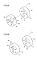
- FIG. 6A is an explanatory view showing the rotation positions of the first member and the second member in the closed state of the valve mechanism, and FIG. 6B shows the rotation positions of the first member and the second member in the open state of the valve mechanism. It is explanatory drawing which shows. It is a perspective view of the catheter hub at the time of administration. It is sectional drawing of the catheter hub of FIG.
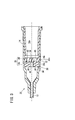
- the catheter assembly 10 includes a catheter 12, a catheter hub 14 connected to the proximal end of the catheter 12, and an internal needle 16 having a sharp cutting edge 16a at the tip and inserted into the catheter 12.
- a needle hub 18 connected to the inner needle 16 and a valve mechanism 20 (medical valve) arranged in the catheter hub 14 are provided.
- the needle hub 18 is gripped by a user (doctor, nurse, etc.), and the tip of the needle hub 18 is punctured into a patient's blood vessel.
- the catheter assembly 10 In the initial state before use (before puncturing the patient), the catheter assembly 10 has a double-tube structure in which the inner needle 16 is inserted into the catheter 12, and the inner needle 16 is only a predetermined length from the tip of the catheter 12. It is protruding.
- the catheter 12 is a flexible, small-diameter tubular member.
- the catheter 12 is made of, for example, a resin material, preferably a soft resin material.
- a hollow catheter hub 14 is connected and fixed to the base end of the catheter 12.
- a valve mechanism 20 is provided in the lumen 14a of the catheter hub 14.
- the indwelling catheter 22 is composed of the catheter 12, the catheter hub 14, and the valve mechanism 20.
- the catheter hub 14 When using the catheter assembly 10, the catheter hub 14 is exposed on the skin with the catheter 12 indwelled in a blood vessel, and is attached and indwelled on the skin with a dressing material, tape, or the like.
- the inner needle 16 is a tubular member having rigidity capable of puncturing the patient's skin, and is made of, for example, a metal material (stainless steel) or the like. A groove for confirming the flash bag of blood may be formed on the upper surface of the tip of the inner needle 16.
- the proximal end portion of the inner needle 16 is arranged inside the lumen 14a of the catheter hub 14.
- the inner needle 16 may be configured as a solid needle.
- the needle hub 18 is connected to the base end portion of the inner needle 16.
- the needle hub 18 has a hub main body 28 that functions as a grip portion that is gripped by the user, and a needle holding portion 30 that protrudes from the hub main body 28 in the distal direction direction and holds the base end portion of the inner needle 16. In the initial state of the catheter assembly 10, the needle holding portion 30 is inserted into the proximal end portion of the catheter hub 14.
- the valve mechanism 20 shown in FIG. 3 has a function of preventing blood from flowing out from the catheter hub 14 due to backflow of blood in the proximal direction, and a function of allowing the drug solution to pass in the distal direction when the drug solution is administered.
- the valve mechanism 20 includes a first member 32 made of an elastic material, a second member 34 arranged adjacent to the first member 32, and an operating member 36 for rotating the second member 34 with respect to the first member 32. I have.
- the first member 32 is formed in a columnar shape, and its outer diameter is formed to be substantially the same as the inner diameter of the inner peripheral surface 14c (see FIG. 3) of the catheter hub 14.
- a tip surface 32a perpendicular to the central axis of the first member 32 is formed on the tip side of the first member 32.
- a proximal end surface 32b perpendicular to the central axis of the first member 32 is formed on the proximal end side of the first member 32.
- the first member 32 is, for example, a synthetic rubber such as polybutadiene-based, nitrile-based, or chloroprene-based, a natural rubber such as polyisoprene, a thermosetting elastomer such as urethane rubber, silicon rubber, or fluororubber, a thermoplastic elastomer, or It is made of a rubber material such as another elastomer.
- a synthetic rubber such as polybutadiene-based, nitrile-based, or chloroprene-based
- a natural rubber such as polyisoprene
- a thermosetting elastomer such as urethane rubber, silicon rubber, or fluororubber
- a thermoplastic elastomer or It is made of a rubber material such as another elastomer.
- the first member 32 is pushed inside the inner peripheral surface 14c of the catheter hub 14 while being elastically compressed.
- the outer surface 32c of the first member 32 is in close contact with the
- a slit 38 is formed in the vicinity of the central axis of the first member 32.
- the slit 38 is formed so as to penetrate the first member 32 in the axial direction so that the inner needle 16 (see FIG. 1) and the like can be inserted in the axial direction.
- the slit 38 is closed by the elastic restoring force of the first member 32, and the inner needle 16 can be inserted while preventing the backflow of blood.
- the slit 38 is formed linearly when viewed from the front, but the slit 38 is not limited to this, and may have various shapes such as a shape in which both ends are branched into a Y shape and an X shape. ..
- a first liquid passage hole 40 is formed at a portion separated from the central axis of the first member 32.
- the first liquid passage hole 40 is formed so as to penetrate the first member 32 in the axial direction, and can allow a liquid such as blood or a drug to pass in the axial direction.
- a pair of first liquid passage holes 40 are provided with the central axis interposed therebetween.
- the number of the first liquid passage holes 40 may be one or three or more.
- the second member 34 is arranged adjacent to the tip end side of the first member 32.
- the central axis (rotating axis) of the second member 34 is arranged on the same axis as the central axis of the first member 32 and the central axis of the catheter hub 14.
- the second member 34 is rotatably attached around the axis of the catheter hub 14, and is rotatably relative to the first member 32.
- the second member 34 is made of a material harder than the first member 32. More preferably, if it is made of a material that can easily slide with respect to the catheter hub 14, the rotation operation becomes smooth and the operability is improved. Examples of the material of the second member 34 include various resin materials such as polypropylene resin.
- the second member 34 is formed in a columnar shape, and its outer diameter is substantially the same as the inner diameter of the inner peripheral surface 14c of the catheter hub 14.
- a tip surface 34a perpendicular to the central axis is formed on the tip side.
- a proximal end surface 34b perpendicular to the central axis is formed on the proximal end side.
- a needle insertion hole 42 is formed in the vicinity of the central axis of the second member 34. The needle insertion hole 42 is formed so as to penetrate the first member 32 in the axial direction, and the inner needle 16 can be inserted in the axial direction.
- a second liquid passage hole 44 is formed at a portion separated from the central axis of the second member 34.
- the second liquid passage hole 44 is formed at the same position in the radial direction as the first liquid passage hole 40 of the first member 32, and when the second member 34 is rotated to a predetermined position, the first liquid passage hole 40 Communicate with.
- the second liquid passage hole 44 is formed so as to penetrate the second member 34 in the axial direction, and by communicating with the first liquid passage hole 40, a liquid such as blood or a drug can pass through. Similar to the first liquid passage hole 40, the second liquid passage holes 44 are provided in pairs with the central axis interposed therebetween.
- the number of the second liquid passage holes 44 may be one or three or more.
- the inner diameter of the second liquid passage hole 44 is formed to be equal to or larger than the inner diameter of the first liquid passage hole 40.
- the base end surface 34b of the second member 34 is a surface facing the tip end surface 32a of the first member 32, and is formed as a flat surface slidable with the tip end surface 32a.
- a pair of protrusions 46 are provided on the base end surface 34b.
- a number of second liquid passage holes 44 equal to the number of the first liquid passage holes 40 are also provided at positions where they can be inserted into the first liquid passage holes 40.
- the protrusion 46 is formed in a hemispherical shape having a diameter slightly larger than the inner diameter of the first liquid passage hole 40, and when inserted into the first liquid passage hole 40, the protrusion 46 is fitted into the first liquid passage hole 40. 1
- the liquid passage hole 40 is liquid-tightly sealed.
- the base end surface 34b of the second member 34 is in close contact with the tip surface 32a of the first member 32 in a liquid-tight manner. You don't have to.
- An operation lever 48 is provided on the outer surface 34c of the second member 34.
- the operating lever 48 is formed in the shape of a rod extending outward in the radial direction of the second member 34.
- the operating lever 48 is inserted into the guide groove 14b (see FIG. 2) of the catheter hub 14, and a part of the operating lever 48 projects to the outside of the catheter hub 14 through the guide groove 14b.
- the guide groove 14b is formed so as to extend in the circumferential direction of the catheter hub 14 over a predetermined angle range, and is configured to guide the rotational operation of the second member 34 through the operating lever 48.
- the guide groove 14b and the operation lever 48 constitute the operation member 36 of the present embodiment.
- the outer surface 34c of the second member 34 is in close contact with the inner peripheral surface 14c of the catheter hub 14, and liquid such as blood flows through the outer side of the outer surface 34c to the proximal end side or It has a structure that does not leak from the guide groove 14b.
- the catheter assembly 10, the valve mechanism 20 (medical valve), and the indwelling catheter 22 of the present embodiment are configured as described above, and their actions will be described below.
- the user grips the needle hub 18 of the catheter assembly 10 in the initial state shown in FIG. To puncture. After the puncture, the user advances the catheter 12 by pushing the catheter hub 14 toward the tip while holding the positions of the needle hub 18 and the inner needle 16, and inserts the catheter 12 into the blood vessel.
- the user After inserting the catheter 12 into the blood vessel for a predetermined length, the user then pulls the needle hub 18 toward the proximal end while holding the position of the indwelling catheter 22, and removes the inner needle 16 from the indwelling catheter 22. At this time, the inner needle 16 is removed from the valve mechanism 20. As a result, the indwelling catheter 22 is indwelled on the patient side. After pulling out the inner needle 16 from the indwelling catheter 22, the user fixes the catheter hub 14 to the patient with a dressing material, tape, or the like.
- a valve mechanism 20 is provided in the catheter hub 14, and even after the inner needle 16 is removed from the valve mechanism 20, the outflow of blood from the catheter hub 14 is prevented.
- the first member 32 and the second member 34 of the valve mechanism 20 are arranged as shown in FIG. 6A, the first liquid passage hole 40 of the first member 32 and the second member 34 of the second member 34. It is in a closed state in which it does not communicate with the liquid passage hole 44.
- the slit 38 of the first member 32 is liquid-tightly closed by the elastic restoring force.
- the protrusion 46 of the second member 34 is inserted into the first liquid passage hole 40, and the first liquid passage hole 40 is liquid-tightly closed by the second member 34. In this way, the valve mechanism 20 prevents the outflow of blood.
- the connector 52 of the infusion tube is inserted into the lumen 14a of the catheter hub 14 on the proximal end side of the indwelling catheter 22 from which the inner needle 16 has been extracted, and the connector 52 of the infusion tube is inserted from the infusion tube. Administer the drug solution to the patient.
- the user rotates the operating lever 48 along the guide groove 14b to the position shown in FIG. 7 to open the valve mechanism 20.
- the positions of the first liquid passage hole 40 of the first member 32 and the second liquid passage hole 44 of the second member 34 in the circumferential direction coincide with each other.
- the first liquid passage hole 40 and the second liquid passage hole 44 communicate with each other, and the liquid can flow.
- the protrusion 46 elastically deforms the first member 32 at a portion other than the first liquid passage hole 40.
- the protrusion 46 forms a gap through which the liquid can pass between the first member 32 and the second member 34, and a part of the liquid can flow through the gap and the needle insertion hole 42.
- the valve mechanism 20 is opened, and the flow of the chemical solution from the proximal end side to the distal end side of the valve mechanism 20 is allowed.
- the user closes the valve mechanism 20 by rotating the operating lever 48 to the position shown in FIG. 6A.
- the user can switch the opening and closing of the valve mechanism 20 by rotating the operation lever 48 as necessary when collecting blood, taking medication, or the like.
- it is not necessary to push the plug into the slit structure of the elastic member as in the conventional check valve, so that deterioration of the sealing property of the valve mechanism 20 can be prevented. Therefore, according to the valve mechanism 20 of the embodiment, the outflow of blood can be prevented even if the opening / closing operation is performed a plurality of times.
- the catheter assembly 10, the valve mechanism 20 (medical valve), and the indwelling catheter 22 of the present embodiment have the following effects.
- the indwelling catheter 22 of the present embodiment includes a catheter 12 to be indwelled in a living body, a catheter hub 14 for holding and fixing the catheter 12, a valve mechanism 20 (medical valve) provided in the lumen 14a of the catheter hub 14. It has.
- the valve mechanism 20 of the indwelling catheter 22 is arranged adjacent to the first member 32 having a slit 38 into which the inner needle 16 can be inserted and a first liquid passage hole 40 through which a liquid passes, and the first member 32.
- a second member 34 having a needle insertion hole 42 through which the inner needle 16 is inserted and a second liquid passage hole 44 through which a liquid is passed, and an operating member 36 for relatively moving the first member 32 and the second member 34.
- the first liquid passage hole 40 and the second liquid passage hole 44 are relatively moved by the operation of the operation member 36, and the first liquid passage hole 40 and the second liquid passage hole 44 are communicated with each other to allow the fluid to flow. It switches between an open state in which the liquid can flow and a closed state in which the first liquid passage hole 40 and the second liquid passage hole 44 are not communicated with each other so that the liquid does not flow.
- the valve mechanism 20 can be opened and closed only by relatively moving the first member 32 and the second member 34. As a result, it is not necessary to push the plug into the elastic member to be sealed when the check valve is opened as in the conventional check valve, so that the sealing property of the valve mechanism 20 can be maintained even if the opening / closing operation is performed a plurality of times. .. As a result, even if the user performs the opening / closing operation of the valve mechanism 20 a plurality of times for blood collection, medication, etc., the outflow of blood can be reliably prevented. Further, since the plug and its operation mechanism like the conventional check valve are not required, the structure can be simplified and the manufacturing cost can be suppressed.
- the first member 32 is made of an elastic material, is fixed to the catheter hub 14, and the second member 34 is rotated with respect to the first member 32 to be displaced into an open state and a closed state. It may be configured to do so.
- the second member 34 which has a relatively better slidability than the first member 32, rotatable, the opening / closing operation can be smoothly performed and the operability is improved.
- the needle insertion hole 42 and the slit 38 are provided near the rotation axis of the second member 34, and the first liquid passage hole 40 and the second liquid passage hole 44 are the times of the second member 34. It may be provided at a position away from the moving axis. With this configuration, the inner needle 16 can be inserted through the needle insertion hole 42 and the slit 38 regardless of the rotation position of the second member 34. Further, by rotating the second member 34, it is possible to switch between communication and closure between the first liquid passage hole 40 and the second liquid passage hole 44, and the structure of the valve mechanism 20 is simplified.
- the operating lever 48 which is a part of the operating member 36, may protrude to the outside of the catheter hub 14, and the second member 34 may be rotatably configured from the outside of the catheter hub 14. With this configuration, the user can easily open and close the valve mechanism 20.
- the outer surfaces 32c and 34c of the first member 32 and the second member 34 may be in liquid-tight contact with the inner peripheral surface 14c of the catheter hub 14. With such a configuration, it is possible to prevent blood from flowing out through the inner peripheral surface 14c of the catheter hub 14.
- the second member 34 has a protrusion 46 on the proximal end surface 34b facing the first member 32, and the protrusion 46 is fitted into the first liquid passage hole 40 of the first member 32 in the closed state. Therefore, the first liquid passage hole 40 may be configured to be liquid-tightly closed. With such a configuration, the sealing property of the first liquid passage hole 40 is improved, and the outflow of blood can be prevented more effectively.
- the first member 32 and the second member 34 may be in close contact with each other in the axial direction.
- the sealing property in a state where the first liquid passage hole 40 and the second liquid passage hole 44 do not match is improved, which is preferable.
- the first liquid passage hole 40 and the second liquid passage hole 44 are separated from the rotation axis of the second member 34 by the same distance in the radial direction, and the second member 34 is rotated. At that time, they may be provided at positions that coincide with each other. As a result, by rotating the second member 34, the first liquid passage hole 40 and the second liquid passage hole 44 are surely communicated with each other, and a sufficient liquid flow rate can be secured.
- the inner diameter of the second liquid passage hole 44 may be formed to have a size equal to or larger than the inner diameter of the first liquid passage hole 40. With such a configuration, a sufficient flow rate of liquid can be secured, which is preferable.
- the valve mechanism 20 (medical valve) of the present embodiment is provided in the lumen 14a of the catheter hub 14 that holds and fixes the catheter 12.
- the valve mechanism 20 (medical valve) is arranged adjacent to a first member 32 having a slit 38 through which an inner needle 16 can be inserted and a first liquid passage hole 40 through which a liquid passes, and a first member 32.
- a second member 34 having a needle insertion hole 42 through which the inner needle 16 is inserted and a second liquid passage hole 44 through which a liquid is passed, and an operating member 36 for relatively moving the first member 32 and the second member 34.
- valve mechanism 20 even when the valve mechanism 20 is opened a plurality of times, the outflow of blood can be reliably prevented.
- the catheter assembly 10 of the present embodiment includes a catheter 12 to be placed in a living body, a catheter hub 14 for holding and fixing the catheter 12, a valve mechanism 20 provided in the lumen 14a of the catheter hub 14, and a valve mechanism 20.
- the present invention relates to a catheter assembly 10 comprising an inner needle 16 inserted through and inserted into the catheter 12 and a needle hub 18 for holding and fixing the inner needle 16.
- the valve mechanism 20 of the catheter assembly 10 is arranged adjacent to a first member 32 having a slit 38 into which an inner needle 16 can be inserted and a first liquid passage hole 40 through which a liquid passes, and a first member 32.
- a second member 34 having a needle insertion hole 42 through which the inner needle 16 is inserted and a second liquid passage hole 44 through which a liquid is passed, and an operating member 36 for relatively moving the first member 32 and the second member 34.
- an open state in which the first liquid passage hole 40 and the second liquid passage hole 44 are communicated with each other to allow fluid to flow by operating the operation member 36, and the first liquid passage hole 40 and the second passage.
- the liquid hole 44 is disconnected from the liquid hole 44, and the state is switched to a closed state in which no fluid flows.
- the catheter assembly 10 from the above viewpoint, even when the valve mechanism 20 is opened a plurality of times, the outflow of blood can be reliably prevented.
- the first member 32 is arranged on the proximal end side and the second member 34 is arranged on the distal end side, but conversely, the first member 32 is arranged on the distal end side and the second member 34 may be arranged on the base end side.
- a part of the catheter hub 14 is configured to be rotatable in the circumferential direction. Then, the second member 34 may be configured to rotate integrally with the rotating portion of the catheter hub 14.
- the second member 34 and the first member 32 are urged in the axial direction to be in close contact with each other in a liquid-tight manner, so that the first liquid passage hole 40 and the second liquid passage hole 44 are sealed in a closed state. You may try to keep the sex.
Abstract
留置カテーテル(22)、医療用弁(20)及びカテーテル組立体(10)に関し、カテーテルハブ(14)の内腔(14a)に設けられる弁機構(20)を、内針(16)が挿通可能なスリット(38)と、液体を通す第1通液孔(40)と、を有する第1部材(32)と、第1部材(32)に隣接して配置され、内針(16)を挿通させる針挿通孔(42)と、液体を通す第2通液孔(44)と、を有する第2部材(34)と、第1通液孔(40)と第2通液孔(44)とを連通させて流体が流通可能な開状態と、第1通液孔(40)と第2通液孔(44)とを非連通にさせて流体が流通しない閉状態とに、第1部材(32)及び第2部材(34)を相対移動させる操作部材(36)と、で構成する。
Description
本発明は、例えば、輸液や輸血等を行う場合に使用される留置カテーテル、医療用弁及びカテーテル組立体に関する。
従来、患者に対して輸液や輸血等を行うために、カテーテル組立体が使用される。この種のカテーテル組立体は、カテーテルと、カテーテル基端に固定されたカテーテルハブと、カテーテル内に挿入された内針と、内針の基端に固定された針ハブとを備える。カテーテル組立体は、カテーテルが患者の血管内に挿入された後、内針をカテーテル及びカテーテルハブから引き抜かれる。その後、カテーテルハブに医療機器が接続されることで、留置されたカテーテル(留置カテーテル)が導入部として機能する。
留置カテーテルの操作において、内針を抜去した後にカテーテルハブから血液が流出して血液による汚染や、医療従事者の血液感染を生じるリスクがある。このような血液の流出を防ぐべく、カテーテルハブ内に、弁を設けたカテーテル組立体も知られている(特表2014-528807号公報)。
カテーテルハブ内の弁は、通常は閉状態となっているため、採血や投薬等を行う場合には、プラグと呼ばれる部品を弁に押し込んで弁を開放させる必要がある。プラグを押し込む際に、弁に負担が掛かり、繰り返し開放させると、弁のシール性が低下してしまう。そのため、繰り返し開放操作を行うと、弁の止血が不十分となりカテーテルハブから血液が流出するという問題がある。
一実施形態は、弁機構を複数回開放した場合であっても、血液の流出を確実に阻止できる留置カテーテル、医療用弁及びカテーテル組立体を提供することを目的とする。
以下の開示の一観点は、生体に留置されるカテーテルと、前記カテーテルを保持固定するカテーテルハブと、前記カテーテルハブの内腔に設けられた弁機構と、を備えた留置カテーテルであって、前記弁機構は、内針が挿通可能なスリットと、液体を通す第1通液孔と、を有する第1部材と、前記第1部材に隣接して配置され、前記内針を挿通させる針挿通孔と、前記液体を通す第2通液孔と、を有する第2部材と、前記第1部材及び前記第2部材を相対移動させる操作部材と、を有し、前記操作部材を操作することにより、前記第1部材及び前記第2部材は、前記第1通液孔と前記第2通液孔とが互いに連通する開状態と、前記第1通液孔と前記第2通液孔とが互いに非連通となる閉状態とに切り替わる、留置カテーテルにある。
別の一観点は、カテーテルを保持固定するカテーテルハブの内腔に設けられた医療用弁であって、内針が挿通可能なスリットと、液体を通す第1通液孔と、を有する第1部材と、前記第1部材に隣接して配置され、前記内針を挿通させる針挿通孔と、前記液体を通す第2通液孔と、を有する第2部材と、前記第1通液孔と前記第2通液孔とを連通させて流体が流通可能な開状態と、前記第1通液孔と前記第2通液孔とを非連通にさせて流体が流通しない閉状態とに、前記第1部材及び前記第2部材を相対移動させる操作部材と、を有する、医療用弁にある。
さらに別の一観点は、生体に留置されるカテーテルと、前記カテーテルを保持固定するカテーテルハブと、前記カテーテルハブの内腔に設けられた弁機構と、前記弁機構を挿通し前記カテーテル内に挿入された内針と、前記内針を保持固定する針ハブと、を備えたカテーテル組立体であって、前記弁機構は、内針が挿通可能なスリットと、液体を通す第1通液孔と、を有する第1部材と、前記第1部材に隣接して配置され、前記内針を挿通させる針挿通孔と、前記液体を通す第2通液孔と、を有する第2部材と、前記第1通液孔と前記第2通液孔とを連通させて流体が流通可能な開状態と、前記第1通液孔と前記第2通液孔とを非連通にさせて流体が流通しない閉状態とに、前記第1部材及び前記第2部材を相対移動させる操作部材と、を有する、カテーテル組立体にある。
上記観点の留置カテーテル、医療用弁及びカテーテル組立体によれば、弁機構を複数回開放した場合であっても、血液の流出を確実に阻止できる。
以下、留置カテーテル、医療用弁及びカテーテル組立体について好適な実施形態を挙げ、添付の図面を参照して詳細に説明する。なお、図面の寸法比率は、説明の都合上、誇張されて実際の比率とは異なる場合がある。
カテーテル組立体10は、図1に示すように、カテーテル12と、カテーテル12の基端に接続されたカテーテルハブ14と、先端に鋭利な刃先16aを有しカテーテル12に挿通された内針16と、内針16に接続された針ハブ18と、カテーテルハブ14内に配置された弁機構20(医療用弁)と、を備える。
カテーテル組立体10は、ユーザ(医師や看護師等)により針ハブ18が把持操作されて、その先端部が患者の血管に穿刺される。カテーテル組立体10は、使用前(患者への穿刺前)の初期状態では、カテーテル12に内針16が挿通された2重管構造となり、且つ内針16がカテーテル12の先端から所定長さだけ突出している。
カテーテル12は、可撓性を有する細径の管状部材である。カテーテル12は、例えば、樹脂材料、好適には軟質樹脂材料により構成される。図1に示すように、カテーテル12の基端には、中空状のカテーテルハブ14が接続固定される。図2及び図3に示すように、カテーテルハブ14の内腔14aには、弁機構20が設けられている。図1に示すように、カテーテル12、カテーテルハブ14及び弁機構20により、留置カテーテル22が構成されている。
カテーテル組立体10の使用に際し、カテーテルハブ14は、カテーテル12が血管に留置された状態で皮膚上に露呈され、ドレッシング材やテープ等により皮膚上に貼り付けられて留置される。
内針16は、患者の皮膚を穿刺可能な剛性を有する管状部材であり、例えば金属材料(ステンレス鋼)等からなる。内針16の先端部上面には、血液のフラッシュバッグ確認用の溝が形成されていてもよい。図1に示すカテーテル組立体10の初期状態で、内針16の基端部は、カテーテルハブ14の内腔14aの内部に配置されている。内針16は、中実針として構成されてもよい。
針ハブ18は、内針16の基端部に接続されている。針ハブ18は、ユーザにより把持される把持部として機能するハブ本体28と、ハブ本体28から先端方向に突出するとともに内針16の基端部を保持した針保持部30とを有する。カテーテル組立体10の初期状態で、針保持部30はカテーテルハブ14の基端部に挿入されている。
図3に示す弁機構20は、基端方向への血液の逆流によるカテーテルハブ14からの血液の流出を防ぐ機能と、薬液投与の際に先端方向への薬液の通過を許容する機能を備えている。弁機構20は、弾性材料よりなる第1部材32と、第1部材32に隣接配置される第2部材34と、第2部材34を第1部材32に対して回動させる操作部材36とを備えている。
図4Aに示すように、第1部材32は円柱状に形成されており、その外径はカテーテルハブ14の内周面14c(図3参照)の内径と略同じ大きさに形成されている。第1部材32の先端側には、第1部材32の中心軸に垂直な先端面32aが形成されている。また、図4Bに示すように、第1部材32の基端側には、第1部材32の中心軸に垂直な基端面32bが形成されている。第1部材32は、例えば、ポリブタジエン系、ニトリル系、クロロプレン系等の合成ゴムや、ポリイソプレン等の天然ゴム、又はウレタンゴム、シリコンゴム、フッ素ゴム等の熱硬化性エラストマー、熱可塑性エラストマー、あるいは他のエラストマー等のゴム材料によって形成されている。図3に示すように、第1部材32は、弾性圧縮されながら、カテーテルハブ14の内周面14cの内側に押し込まれている。そして、第1部材32の外側面32cが内周面14cと密着しており、第1部材32が内周面14cを液密及び気密に閉塞している。
図4Aに示すように、第1部材32の中心軸付近には、スリット38が形成されている。図4Bに示すように、スリット38は、第1部材32の軸方向に貫通して形成されており、内針16(図1参照)等を軸方向に挿通可能になっている。スリット38は、第1部材32の弾性復元力によって閉塞しており血液の逆流を阻止しつつ、内針16を挿通させることができる。スリット38は、正面視して線状に形成されているが、これに限定されるものではなく、両端がY字型に分岐した形状や、X字型の形状等、様々な形状としてもよい。
第1部材32の中心軸から離間した部位には、第1通液孔40が形成されている。第1通液孔40は、第1部材32を軸方向に貫通して形成されており、血液や薬剤等の液体を軸方向に通過させることができる。図4Aに示すように、第1通液孔40は、中心軸を挟んで一対設けられている。なお、第1通液孔40の数は1つであってもよいし、3つ以上であってもよい。
図3に示すように、第2部材34は、第1部材32の先端側に隣接して配置されている。第2部材34の中心軸(回動軸)は第1部材32の中心軸及びカテーテルハブ14の中心軸と同一の軸線上に配置されている。第2部材34は、カテーテルハブ14の軸回りに回動可能に取り付けられており、第1部材32に対して相対的に回動可能となっている。
第2部材34は、第1部材32よりも硬質の材料よりなる。より好ましくは、カテーテルハブ14に対する摺動が容易な材料で構成すると、回動操作が円滑となり、操作性が向上して好適である。第2部材34の材料としては、例えば、ポリプロピレン樹脂等の各種樹脂材料が挙げられる。
図5Aに示すように、第2部材34は円柱状に形成されており、その外径は、カテーテルハブ14の内周面14cの内径と略同じサイズとなっている。先端側に中心軸に垂直な先端面34aが形成されている。また、図5Bに示すように、基端側には、中心軸に垂直な基端面34bが形成されている。第2部材34の中心軸付近には、針挿通孔42が形成されている。針挿通孔42は、第1部材32の軸方向に貫通して形成されており、内針16を軸方向に挿通させることができる。
第2部材34の中心軸から離間した部位には、第2通液孔44が形成されている。第2通液孔44は、第1部材32の第1通液孔40と径方向に同じ位置に形成されており、第2部材34を所定位置に回動させると、第1通液孔40と連通する。第2通液孔44は、第2部材34を軸方向に貫通して形成されており、第1通液孔40と連通することで、血液や薬剤等の液体を通過させることができる。第2通液孔44は、第1通液孔40と同様に、中心軸を挟んで一対設けられている。なお、第2通液孔44の数は1つであってもよいし、3つ以上であってもよい。また、通過する液体の流量(通液流量)を確保するべく、第2通液孔44の内径は、第1通液孔40の内径と同等以上に形成されている。
第2部材34の基端面34bは、第1部材32の先端面32aに対向する面であり、先端面32aと摺動可能な平坦面として形成されている。基端面34bには、一対の突起46が設けられている。第1通液孔40に挿入可能な位置に、第1通液孔40と等しい数の第2通液孔44も設けられている。突起46は、第1通液孔40の内径よりも僅かに大きな直径の半球状に形成されており、第1通液孔40に挿入されると、第1通液孔40に嵌め込まれて第1通液孔40を液密に封止する。このように、本実施形態において、第1通液孔40の封止は、突起46によって行われるため、第2部材34の基端面34bは、第1部材32の先端面32aと液密に密着していなくてもよい。
第2部材34の外側面34cには、操作レバー48が設けられている。操作レバー48は、第2部材34の径方向外方に延び出た棒状に形成されている。操作レバー48は、カテーテルハブ14の案内溝14b(図2参照)に挿入されており、操作レバー48の一部は、案内溝14bを通じてカテーテルハブ14の外側に突出している。案内溝14bは、カテーテルハブ14の周方向に所定の角度範囲に亘って延びて形成されており、操作レバー48を通じた第2部材34の回動動作を案内するように構成されている。この案内溝14b及び操作レバー48によって、本実施形態の操作部材36が構成される。
図3に示すように、第2部材34の外側面34cは、カテーテルハブ14の内周面14cと液密に密着しており、外側面34cの外側を通じて血液等の液体が、基端側や案内溝14bから漏洩しない構造となっている。
本実施形態のカテーテル組立体10、弁機構20(医療用弁)及び留置カテーテル22は以上のように構成され、以下その作用について説明する。
カテーテル組立体10の使用において、ユーザ(医師や看護師等)は、図1に示す初期状態のカテーテル組立体10の針ハブ18を把持し、内針16及びカテーテル12の先端部を患者の血管に穿刺する。穿刺後、ユーザは、針ハブ18及び内針16の位置を保持したまま、カテーテルハブ14を先端方向に押すことにより、カテーテル12を前進させ、カテーテル12を血管内に挿入してゆく。
血管内にカテーテル12を所定長さ挿入したら、次に、ユーザは留置カテーテル22の位置を保持した状態で、針ハブ18を基端方向に引っ張り、内針16を留置カテーテル22から抜去する。この際、弁機構20から内針16が抜去される。この結果、留置カテーテル22が患者側に留置された状態となる。留置カテーテル22から内針16を引き抜いた後、ユーザはドレッシング材やテープ等でカテーテルハブ14を患者に固定する。
カテーテルハブ14内には、弁機構20が設けられており、弁機構20から内針16が抜去された後においても、カテーテルハブ14からの血液の流出は阻止される。初期状態において、弁機構20の第1部材32及び第2部材34は、図6Aに示すように配置されており、第1部材32の第1通液孔40と、第2部材34の第2通液孔44とが連通しない閉状態となっている。このとき、図3に示すように、第1部材32のスリット38が弾性復元力により液密に閉塞される。また、第1通液孔40には、第2部材34の突起46が挿入され、第2部材34によって第1通液孔40が液密に閉塞される。このようにして、弁機構20によって血液の流出が阻止される。
次に、図8に示すように、内針16が抜き取られた留置カテーテル22の基端側であって、カテーテルハブ14の内腔14aに、輸液チューブのコネクタ52を挿入して、輸液チューブから患者への薬液の投与を実施する。
ユーザは、カテーテルハブ14に輸液チューブを接続した後、操作レバー48を案内溝14bに沿って図7に示す位置に回動させて弁機構20を開状態とする。弁機構20の開状態においては、図6Bに示すように、第1部材32の第1通液孔40と、第2部材34の第2通液孔44の周方向の位置が一致する。その結果、図8に示すように、第1通液孔40と第2通液孔44とが連通して、液体の流通が可能となる。このとき、突起46は、第1通液孔40以外の部分で第1部材32を弾性変形させている。突起46によって、第1部材32と第2部材34との間に液体の通過可能な隙間が形成され、液体の一部は、その隙間と針挿通孔42を通じて流通可能である。これにより、弁機構20が開通し、弁機構20の基端側から先端側への薬液の流動が許容される。
薬液の投与の完了後は、ユーザは、操作レバー48を図6Aの位置に回動させることにより、弁機構20を閉塞させる。ユーザは、採血や投薬等の際に、必要に応じて操作レバー48を回動させることで、弁機構20の開閉を切り換えることができる。弁機構20の開閉の切換においては、従来の逆止弁のように、弾性部材のスリット構造にプラグを押し込む必要がないため、弁機構20のシール性の劣化を防止できる。そのため、実施形態の弁機構20によれば、開閉操作を複数回行っても、血液の流出を防止できる。
本実施形態のカテーテル組立体10、弁機構20(医療用弁)及び留置カテーテル22は、以下の効果を奏する。
本実施形態の留置カテーテル22は、生体に留置されるカテーテル12と、カテーテル12を保持固定するカテーテルハブ14と、カテーテルハブ14の内腔14aに設けられた弁機構20(医療用弁)と、を備えている。この留置カテーテル22の弁機構20は、内針16が挿通可能なスリット38と、液体を通す第1通液孔40と、を有する第1部材32と、第1部材32に隣接して配置され、内針16を挿通させる針挿通孔42と、液体を通す第2通液孔44と、を有する第2部材34と、第1部材32及び第2部材34を相対移動させる操作部材36と、を有し、前記操作部材36の操作により、第1通液孔40及び第2通液孔44を相対移動させ、第1通液孔40と第2通液孔44とを連通させて流体が流通可能な開状態と、第1通液孔40と第2通液孔44とを非連通にさせて流体が流通しない閉状態とに切り替わる。
上記の構成によれば、弁機構20が第1部材32と第2部材34とを相対移動させるだけで開閉を行える。これにより、従来の逆止弁のように開状態とする際に、シールを行う弾性部材にプラグを押し込む必要がなくなるため、複数回にわたって開閉操作を行っても弁機構20のシール性を維持できる。これにより、ユーザが、採血や投薬等のために、弁機構20の開閉操作を複数回行っても血液の流出を確実に防止することができる。また、従来の逆止弁のようなプラグとその操作機構が不要となるため、構造が簡素化され、製造コストを抑制できる。
上記の留置カテーテル22において、第1部材32は弾性材料よりなり、カテーテルハブ14に固定され、第2部材34が第1部材32に対して回動することにより、開状態と閉状態とに変位するように構成してもよい。このように、第1部材32よりも相対的に摺動性のよい第2部材34を回動可能とすることにより、開閉操作を円滑に行うことができ、操作性が向上する。
上記の留置カテーテル22において、針挿通孔42及びスリット38は第2部材34の回動軸付近に設けられており、第1通液孔40及び第2通液孔44は第2部材34の回動軸から離間した位置に設けられていてもよい。このように構成することで、第2部材34の回転位置にかかわらず、針挿通孔42及びスリット38を通じて内針16を挿通させることができる。また、第2部材34の回動により、第1通液孔40と第2通液孔44との連通と閉塞とを切り換えることができ、弁機構20の構造が簡素化される。
上記の留置カテーテル22において、操作部材36の一部である操作レバー48がカテーテルハブ14の外側に突出しており、カテーテルハブ14の外側から第2部材34を回動可能に構成してもよい。このように構成することで、ユーザが弁機構20の開閉操作を容易に行うことができる。
上記の留置カテーテル22において、第1部材32及び第2部材34の外側面32c、34cは、カテーテルハブ14の内周面14cに液密に接触してもよい。このように構成することにより、カテーテルハブ14の内周面14cを介した血液の流出を防止できる。
上記の留置カテーテル22において、第2部材34は第1部材32に対向する基端面34bに突起46を有し、突起46は、閉状態において、第1部材32の第1通液孔40に嵌め込まれて第1通液孔40を液密に閉塞可能に構成してもよい。このように構成することにより、第1通液孔40のシール性が向上し、血液の流出をより効果的に防止できる。
上記の留置カテーテル22において、第1部材32と第2部材34とは軸方向に密着してもよい。第1部材32と第2部材34とが密着することにより、第1通液孔40と第2通液孔44とが一致していない状態でのシール性が向上して好適である。
上記の留置カテーテル22において、第1通液孔40及び第2通液孔44は、第2部材34の回動軸から径方向に同じ距離離間しており、且つ第2部材34を回動させた際に、互いに一致する位置に設けられていてもよい。これにより、第2部材34を回動させることで、第1通液孔40と第2通液孔44とが確実に連通し、十分な通液流量を確保できる。
上記の留置カテーテル22において、第2通液孔44の内径は、第1通液孔40の内径と同等以上の寸法に形成されていてもよい。このように構成することで、十分な通液流量を確保できて好適である。
本実施形態の弁機構20(医療用弁)は、カテーテル12を保持固定するカテーテルハブ14の内腔14aに設けられている。その弁機構20(医療用弁)は、内針16が挿通可能なスリット38と、液体を通す第1通液孔40と、を有する第1部材32と、第1部材32に隣接して配置され、内針16を挿通させる針挿通孔42と、液体を通す第2通液孔44と、を有する第2部材34と、第1部材32及び第2部材34を相対移動させる操作部材36と、を有し、前記操作部材36の操作により、第1通液孔40と第2通液孔44とを連通させて流体が流通可能な開状態と、第1通液孔40と第2通液孔44とを非連通にさせて流体が流通しない閉状態とに切り替わる。
上記観点の弁機構20によれば、弁機構20を複数回開放した場合であっても、血液の流出を確実に阻止できる。
本実施形態のカテーテル組立体10は、生体に留置されるカテーテル12と、カテーテル12を保持固定するカテーテルハブ14と、カテーテルハブ14の内腔14aに設けられた弁機構20と、弁機構20を挿通し、カテーテル12内に挿入された内針16と、内針16を保持固定する針ハブ18と、を備えたカテーテル組立体10に関する。そのカテーテル組立体10の弁機構20は、内針16が挿通可能なスリット38と、液体を通す第1通液孔40と、を有する第1部材32と、第1部材32に隣接して配置され、内針16を挿通させる針挿通孔42と、液体を通す第2通液孔44と、を有する第2部材34と、第1部材32及び第2部材34を相対移動させる操作部材36と、を有し、前記操作部材36の操作により、第1通液孔40と第2通液孔44とを連通させて流体が流通可能な開状態と、第1通液孔40と第2通液孔44とを非連通にさせて流体が流通しない閉状態とに切り替わる。
上記観点のカテーテル組立体10によれば、弁機構20を複数回開放した場合であっても、血液の流出を確実に阻止できる。
(その他の変形例)
本実施形態は、上記の例に限定されるものではなく以下の変更を行ってもよい。
本実施形態は、上記の例に限定されるものではなく以下の変更を行ってもよい。
図3に示す例では、第1部材32が基端側に配置され、第2部材34が先端側に配置されていたが、逆に、第1部材32を先端側に配置し、第2部材34を基端側に配置してもよい。
操作部材36を、第2部材34の外側面34cから延び出た操作レバー48と、カテーテルハブ14の案内溝14bで構成する代わりに、カテーテルハブ14の一部を周方向に回動可能に構成し、第2部材34をカテーテルハブ14の回動部分と一体的に回動するように構成してもよい。
第2部材34の基端面34bに突起46を設けなくてもよい。この場合には、第2部材34と第1部材32とを軸方向に付勢して液密に密着させることにより、第1通液孔40と第2通液孔44との閉状態のシール性を保つようにしてもよい。
上記において、留置カテーテル、医療用弁(弁機構)及びカテーテル組立体について、好適な実施形態を挙げて説明したが、本発明は上記実施形態に限定されるものではなく、本発明の趣旨を逸脱しない範囲において、種々の改変が可能なことは言うまでもない。
Claims (11)
- 生体に留置されるカテーテルと、
前記カテーテルを保持固定するカテーテルハブと、
前記カテーテルハブの内腔に設けられた弁機構と、を備えた留置カテーテルであって、
前記弁機構は、
内針が挿通可能なスリットと、液体を通す第1通液孔と、を有する第1部材と、
前記第1部材に隣接して配置され、前記内針を挿通させる針挿通孔と、前記液体を通す第2通液孔と、を有する第2部材と、
前記第1部材及び前記第2部材を相対移動させる操作部材と、
を有し、
前記操作部材を操作することにより、前記第1部材及び前記第2部材は、前記第1通液孔と前記第2通液孔とが互いに連通する開状態と、前記第1通液孔と前記第2通液孔とが互いに非連通となる閉状態とに切り替わる、留置カテーテル。 - 請求項1記載の留置カテーテルであって、前記第1部材は弾性材料よりなり、前記カテーテルハブに固定され、前記第2部材が前記第1部材に対して回動することにより、前記開状態と前記閉状態とに変位する、留置カテーテル。
- 請求項2記載の留置カテーテルであって、前記針挿通孔及び前記スリットは前記第2部材の回動軸付近に設けられており、前記第1通液孔及び前記第2通液孔は前記第2部材の回動軸から離間した位置に設けられている、留置カテーテル。
- 請求項2又は3記載の留置カテーテルであって、前記操作部材の一部が前記カテーテルハブの外側に突出しており、前記カテーテルハブの外側から前記第2部材を回動させる、留置カテーテル。
- 請求項4記載の留置カテーテルであって、前記第1部材及び前記第2部材の外側面は、前記カテーテルハブの内周面に液密に接触している、留置カテーテル。
- 請求項1~5のいずれか1項に記載の留置カテーテルであって、前記第2部材は前記第1部材に対向する面に突起を有し、前記突起は、前記閉状態において、前記第1部材の前記第1通液孔に嵌め込まれて前記第1通液孔を液密に閉塞可能である、留置カテーテル。
- 請求項1~6のいずれか1項に記載の留置カテーテルであって、前記第1部材と前記第2部材とは軸方向に密着している、留置カテーテル。
- 請求項2~5のいずれか1項に記載の留置カテーテルであって、前記第1通液孔及び前記第2通液孔は、前記第2部材の回動軸から径方向に同じ距離離間しており、且つ前記第2部材を回動させた際に、互いに一致する位置に設けられている、留置カテーテル。
- 請求項1~8のいずれか1項に記載の留置カテーテルであって、前記第2通液孔の内径は、前記第1通液孔の内径と同等以上の寸法に形成されている、留置カテーテル。
- カテーテルを保持固定するカテーテルハブの内腔に設けられた医療用弁であって、
内針が挿通可能なスリットと、液体を通す第1通液孔と、を有する第1部材と、
前記第1部材に隣接して配置され、前記内針を挿通させる針挿通孔と、前記液体を通す第2通液孔と、を有する第2部材と、
前記第1通液孔と前記第2通液孔とを連通させて流体が流通可能な開状態と、前記第1通液孔と前記第2通液孔とを非連通にさせて流体が流通しない閉状態とに、前記第1部材及び前記第2部材を相対移動させる操作部材と、
を有する、医療用弁。 - 生体に留置されるカテーテルと、
前記カテーテルを保持固定するカテーテルハブと、
前記カテーテルハブの内腔に設けられた弁機構と、
前記弁機構を挿通し前記カテーテル内に挿入された内針と、
前記内針を保持固定する針ハブと、
を備えたカテーテル組立体であって、
前記弁機構は、
前記内針が挿通可能なスリットと、液体を通す第1通液孔と、を有する第1部材と、
前記第1部材に隣接して配置され、前記内針を挿通させる針挿通孔と、前記液体を通す第2通液孔と、を有する第2部材と、
前記第1通液孔と前記第2通液孔とを連通させて流体が流通可能な開状態と、前記第1通液孔と前記第2通液孔とを非連通にさせて流体が流通しない閉状態とに、前記第1部材及び前記第2部材を相対移動させる操作部材と、
を有する、カテーテル組立体。
Priority Applications (2)
| Application Number | Priority Date | Filing Date | Title |
|---|---|---|---|
| JP2022507161A JPWO2021182366A1 (ja) | 2020-03-09 | 2021-03-08 | |
| US17/901,816 US20220409864A1 (en) | 2020-03-09 | 2022-09-01 | Indwelling catheter, medical valve, and catheter assembly |
Applications Claiming Priority (2)
| Application Number | Priority Date | Filing Date | Title |
|---|---|---|---|
| JP2020039811 | 2020-03-09 | ||
| JP2020-039811 | 2020-03-09 |
Related Child Applications (1)
| Application Number | Title | Priority Date | Filing Date |
|---|---|---|---|
| US17/901,816 Continuation US20220409864A1 (en) | 2020-03-09 | 2022-09-01 | Indwelling catheter, medical valve, and catheter assembly |
Publications (1)
| Publication Number | Publication Date |
|---|---|
| WO2021182366A1 true WO2021182366A1 (ja) | 2021-09-16 |
Family
ID=77671723
Family Applications (1)
| Application Number | Title | Priority Date | Filing Date |
|---|---|---|---|
| PCT/JP2021/008862 WO2021182366A1 (ja) | 2020-03-09 | 2021-03-08 | 留置カテーテル、医療用弁及びカテーテル組立体 |
Country Status (3)
| Country | Link |
|---|---|
| US (1) | US20220409864A1 (ja) |
| JP (1) | JPWO2021182366A1 (ja) |
| WO (1) | WO2021182366A1 (ja) |
Citations (8)
| Publication number | Priority date | Publication date | Assignee | Title |
|---|---|---|---|---|
| JPH0315533U (ja) * | 1989-02-03 | 1991-02-15 | ||
| JP2002239012A (ja) * | 2001-02-16 | 2002-08-27 | Jms Co Ltd | 案内器具用逆止弁およびカテーテル案内器具 |
| JP2002263197A (ja) * | 2001-03-12 | 2002-09-17 | Medikit Kk | 留置用カテーテル |
| JP2010142363A (ja) * | 2008-12-17 | 2010-07-01 | Nipro Corp | 医療用弁 |
| JP2013523374A (ja) * | 2010-04-13 | 2013-06-17 | ヴィグメッド アーベー | ポリマーカテーテル針先保護具 |
| JP2016527028A (ja) * | 2013-07-30 | 2016-09-08 | ベクトン・ディキンソン・アンド・カンパニーBecton, Dickinson And Company | 可撓性保持アームを有するアクチュエータを採用する血液制御カテーテル弁 |
| US20170011997A1 (en) * | 2013-12-20 | 2017-01-12 | Intel Corporation | Thickened Stress Relief and Power Distribution Layer |
| JP2018515182A (ja) * | 2015-05-13 | 2018-06-14 | ベー・ブラウン・メルズンゲン・アクチエンゲゼルシャフトB.Braun Melsungen Aktiengesellschaft | 封を備えるカテーテル装置と関連する方法 |
-
2021
- 2021-03-08 WO PCT/JP2021/008862 patent/WO2021182366A1/ja active Application Filing
- 2021-03-08 JP JP2022507161A patent/JPWO2021182366A1/ja active Pending
-
2022
- 2022-09-01 US US17/901,816 patent/US20220409864A1/en active Pending
Patent Citations (8)
| Publication number | Priority date | Publication date | Assignee | Title |
|---|---|---|---|---|
| JPH0315533U (ja) * | 1989-02-03 | 1991-02-15 | ||
| JP2002239012A (ja) * | 2001-02-16 | 2002-08-27 | Jms Co Ltd | 案内器具用逆止弁およびカテーテル案内器具 |
| JP2002263197A (ja) * | 2001-03-12 | 2002-09-17 | Medikit Kk | 留置用カテーテル |
| JP2010142363A (ja) * | 2008-12-17 | 2010-07-01 | Nipro Corp | 医療用弁 |
| JP2013523374A (ja) * | 2010-04-13 | 2013-06-17 | ヴィグメッド アーベー | ポリマーカテーテル針先保護具 |
| JP2016527028A (ja) * | 2013-07-30 | 2016-09-08 | ベクトン・ディキンソン・アンド・カンパニーBecton, Dickinson And Company | 可撓性保持アームを有するアクチュエータを採用する血液制御カテーテル弁 |
| US20170011997A1 (en) * | 2013-12-20 | 2017-01-12 | Intel Corporation | Thickened Stress Relief and Power Distribution Layer |
| JP2018515182A (ja) * | 2015-05-13 | 2018-06-14 | ベー・ブラウン・メルズンゲン・アクチエンゲゼルシャフトB.Braun Melsungen Aktiengesellschaft | 封を備えるカテーテル装置と関連する方法 |
Also Published As
| Publication number | Publication date |
|---|---|
| US20220409864A1 (en) | 2022-12-29 |
| JPWO2021182366A1 (ja) | 2021-09-16 |
Similar Documents
| Publication | Publication Date | Title |
|---|---|---|
| USRE49056E1 (en) | Access device | |
| JP5033636B2 (ja) | 留置針組立体 | |
| JP4921779B2 (ja) | 留置針 | |
| JP5744722B2 (ja) | 半径方向に圧縮可能な血液コントロールバルブ | |
| JP4906508B2 (ja) | 留置針組立体 | |
| US8192404B2 (en) | Indwelling needle assembly | |
| EP3077038B1 (en) | Cuttable catheter hub with integrated hemostasis valve | |
| WO2006100847A1 (ja) | 留置針装置 | |
| JP2024020412A (ja) | カテーテル組立体 | |
| WO2017164223A1 (ja) | カテーテル、切換デバイス及びカテーテルの操作方法 | |
| EP2316503A2 (en) | Valve disc and combination filling device using the valve disc, and tube, pipe jointing device, connection port manufacturing device, and pipe jointing system | |
| WO2021182366A1 (ja) | 留置カテーテル、医療用弁及びカテーテル組立体 | |
| EP3593852B1 (en) | Iv catheter assemblies with injection ports | |
| EP3205369B1 (en) | Catheter hub with sealed access port | |
| JP7440491B2 (ja) | カテーテル組立体 | |
| JP4966860B2 (ja) | 留置針組立体 | |
| WO2013140983A1 (ja) | 医療用針 | |
| US11969559B2 (en) | Catheter hub with sealed access port | |
| JP2012029974A (ja) | 留置針組立体 | |
| JP2024020496A (ja) | カテーテル組立体 |
Legal Events
| Date | Code | Title | Description |
|---|---|---|---|
| 121 | Ep: the epo has been informed by wipo that ep was designated in this application |
Ref document number: 21767094 Country of ref document: EP Kind code of ref document: A1 |
|
| ENP | Entry into the national phase |
Ref document number: 2022507161 Country of ref document: JP Kind code of ref document: A |
|
| NENP | Non-entry into the national phase |
Ref country code: DE |
|
| 122 | Ep: pct application non-entry in european phase |
Ref document number: 21767094 Country of ref document: EP Kind code of ref document: A1 |