WO2021182363A1 - 電力変換装置 - Google Patents
電力変換装置 Download PDFInfo
- Publication number
- WO2021182363A1 WO2021182363A1 PCT/JP2021/008852 JP2021008852W WO2021182363A1 WO 2021182363 A1 WO2021182363 A1 WO 2021182363A1 JP 2021008852 W JP2021008852 W JP 2021008852W WO 2021182363 A1 WO2021182363 A1 WO 2021182363A1
- Authority
- WO
- WIPO (PCT)
- Prior art keywords
- power supply
- control
- current
- value
- unit
- Prior art date
- Legal status (The legal status is an assumption and is not a legal conclusion. Google has not performed a legal analysis and makes no representation as to the accuracy of the status listed.)
- Ceased
Links
Images






Classifications
-
- B—PERFORMING OPERATIONS; TRANSPORTING
- B60—VEHICLES IN GENERAL
- B60L—PROPULSION OF ELECTRICALLY-PROPELLED VEHICLES; SUPPLYING ELECTRIC POWER FOR AUXILIARY EQUIPMENT OF ELECTRICALLY-PROPELLED VEHICLES; ELECTRODYNAMIC BRAKE SYSTEMS FOR VEHICLES IN GENERAL; MAGNETIC SUSPENSION OR LEVITATION FOR VEHICLES; MONITORING OPERATING VARIABLES OF ELECTRICALLY-PROPELLED VEHICLES; ELECTRIC SAFETY DEVICES FOR ELECTRICALLY-PROPELLED VEHICLES
- B60L1/00—Supplying electric power to auxiliary equipment of vehicles
-
- B—PERFORMING OPERATIONS; TRANSPORTING
- B60—VEHICLES IN GENERAL
- B60L—PROPULSION OF ELECTRICALLY-PROPELLED VEHICLES; SUPPLYING ELECTRIC POWER FOR AUXILIARY EQUIPMENT OF ELECTRICALLY-PROPELLED VEHICLES; ELECTRODYNAMIC BRAKE SYSTEMS FOR VEHICLES IN GENERAL; MAGNETIC SUSPENSION OR LEVITATION FOR VEHICLES; MONITORING OPERATING VARIABLES OF ELECTRICALLY-PROPELLED VEHICLES; ELECTRIC SAFETY DEVICES FOR ELECTRICALLY-PROPELLED VEHICLES
- B60L3/00—Electric devices on electrically-propelled vehicles for safety purposes; Monitoring operating variables, e.g. speed, deceleration or energy consumption
-
- H—ELECTRICITY
- H02—GENERATION; CONVERSION OR DISTRIBUTION OF ELECTRIC POWER
- H02J—ELECTRIC POWER NETWORKS; CIRCUIT ARRANGEMENTS OR SYSTEMS FOR SUPPLYING OR DISTRIBUTING ELECTRIC POWER; SYSTEMS FOR STORING ELECTRIC ENERGY
- H02J7/00—Circuit arrangements for charging or discharging batteries or for supplying loads from batteries
-
- H—ELECTRICITY
- H02—GENERATION; CONVERSION OR DISTRIBUTION OF ELECTRIC POWER
- H02M—APPARATUS FOR CONVERSION BETWEEN AC AND AC, BETWEEN AC AND DC, OR BETWEEN DC AND DC, AND FOR USE WITH MAINS OR SIMILAR POWER SUPPLY SYSTEMS; CONVERSION OF DC OR AC INPUT POWER INTO SURGE OUTPUT POWER; CONTROL OR REGULATION THEREOF
- H02M3/00—Conversion of DC power input into DC power output
- H02M3/22—Conversion of DC power input into DC power output with intermediate conversion into AC
- H02M3/24—Conversion of DC power input into DC power output with intermediate conversion into AC by static converters
- H02M3/28—Conversion of DC power input into DC power output with intermediate conversion into AC by static converters using discharge tubes with control electrode or semiconductor devices with control electrode to produce the intermediate AC
Definitions
- This disclosure relates to a power conversion device.
- the inventor of the present application envisioned a power supply system in which a first power supply that outputs a constant voltage and a second power supply that outputs a constant current are connected in parallel as a power supply system in which a plurality of power supplies are connected in parallel.
- this power supply system there is a concern that the output voltage of the second power supply may exceed the target voltage of the power supply system when the output current of the first power supply drops or stops due to a sudden drop in the load current or the like. In order to suppress such a voltage rise, it is necessary to promptly change the current limit value for performing constant current control to a smaller value.
- the present disclosure discloses that in a power supply system in which a second power supply is connected in parallel to a first power supply that outputs a constant voltage, a second power supply is used when the output voltage of the power supply system rises during constant current operation of the second power supply.
- One of the purposes is to quickly suppress the output current of.
- the power conversion device which is one of the present disclosures, is A power conversion device used in a power supply system having a first power supply that outputs a constant voltage based on a first target voltage and the first power supply performs power conversion between a first conductive path and a second conductive path.
- a second power source connected in parallel to the first power source between the first conductive path and the second conductive path is provided.
- the second power source includes a power conversion unit that performs power conversion between the first conductive path and the second conductive path, and a drive unit that drives the power conversion unit.
- the drive unit switches between a first control for operating the power conversion unit in a constant current mode based on a current limit value and a second control for operating the power conversion unit in a mode different from the constant current mode.
- the drive unit is lower than the current limit value when the output voltage of the second power supply reaches a predetermined rising state during the first control or when the release condition for canceling the constant current mode is satisfied.
- a third control is performed to output the current to
- the power conversion device which is one of the present disclosures, is a power supply system in which a second power supply is connected in parallel to a first power supply that outputs a constant voltage, and the output voltage of the power supply system during constant current operation of the second power supply. When the voltage rises, the output current of the second power supply can be quickly suppressed.
- FIG. 1 is a block diagram schematically illustrating an in-vehicle power supply system including the power conversion device of the first embodiment of the present disclosure.
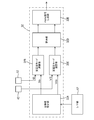
- FIG. 2 is a block diagram schematically illustrating the electrical configuration of the power conversion device of the first embodiment.
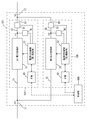
- FIG. 3 is a circuit diagram illustrating a specific configuration of a first power conversion unit in the power conversion device of the first embodiment.
- FIG. 4 is a circuit diagram illustrating a specific configuration of a second power conversion unit in the power conversion device of the first embodiment.
- FIG. 5 is a functional block diagram showing the functions executed by the power supply control unit by blocks.
- FIG. 6 is a block diagram schematically illustrating the configuration of the control unit in the power conversion device of the first embodiment.
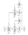
- FIG. 7 is a flowchart illustrating the flow of control performed by the in-power supply control unit (drive unit) of the second power supply in the power conversion device of the first embodiment.
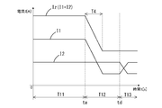
- FIG. 8 is a graph in the case where the load current suddenly decreases during the first control (constant current control) in the power conversion device of FIG.
- FIG. 8 shows the output current value I1 of the first power supply, the output current value I2 of the second power supply, and the total current value Iz when the control unit in the power supply of the second power supply does not perform the third control (current suppression control). It is a graph which shows the relationship.
- FIG. 9 is a graph relating to the operation of the power conversion device of the first embodiment under the same conditions as in FIG.
- FIG. 8 shows the output current value I1 of the first power supply, the output current value I2 of the second power supply, and the total current value Iz when the control unit in the power supply of the second power supply can perform the third control (current suppression control). It is a graph which shows the relationship.
- FIG. 10 shows the output current value I1 of the first power supply, the output current value I2 of the second power supply, and the total current value Iz when the control unit in the power supply of the second power supply does not perform the third control (current suppression control). It is a graph which shows the relationship.
- FIG. 9 shows the output current value I1 of the first power supply, the output current value I2 of the second power supply, and the total current value Iz when the control unit in the power supply of the second power supply can perform the third control (current suppression control). It is a graph which shows the relationship.
- FIG. 10 shows the output current value I1 of the first power supply, the output current value I2 of the second power supply, and the total current value Iz when the control unit in the power supply
- FIG. 10 is a graph when the output current value I1 of the first power supply becomes 0 according to the sudden decrease in the load current.
- FIG. 11 is a graph relating to the operation of the power conversion device of the first embodiment under the same circumstances as in FIG.
- FIG. 11 shows the output current value I1 of the first power supply, the output current value I2 of the second power supply, and the total current value Iz when the control unit in the power supply of the second power supply can perform the third control (current suppression control). It is a graph which shows the relationship.
- Power conversion used in a power supply system including a first power supply that outputs a constant voltage based on a first target voltage and the first power supply performs power conversion between a first conductive path and a second conductive path.
- the apparatus includes a second power source connected in parallel to the first power source between the first conductive path and the second conductive path, and the second power source is the first conductive path. It has a power conversion unit that performs power conversion between the second conductive path and a drive unit that drives the power conversion unit, and the drive unit performs the power conversion in a constant current mode based on a current limit value.
- the first control for operating the unit and the second control for operating the power conversion unit in a mode different from the constant current mode are switched, and the drive unit outputs the second power supply during the first control.
- the power conversion device of the above [1] enables the second power supply to perform a constant current operation in a power supply system in which the second power supply is connected in parallel to the first power supply that outputs a constant voltage. Further, the power conversion device described above has a second power conversion device when the output voltage of the power supply system actually rises to a "predetermined rise state" during the first control (control to operate in the constant current mode) of the second power supply. The power supply itself can quickly switch to the third control (control that suppresses the current). Alternatively, the power conversion device described above is in a state in which the output voltage of the power supply system can be increased by satisfying the condition for releasing the constant current mode during the first control (control to operate in the constant current mode) of the second power supply.
- the second power source itself can quickly switch to the third control (control that suppresses the current). That is, this power conversion device suppresses the output current of the second power supply even when there is a concern that the output voltage of the power supply system may rise during the first control of the second power supply (control to operate in the constant current mode).
- the third control can be quickly shifted to, and the rise in the output voltage of the power supply system can be quickly suppressed.
- the power conversion device of the above [2] more easily realizes a configuration capable of determining whether or not the output voltage of the power supply system has increased during the first control (control to operate in the constant current mode) of the second power supply. can do.
- the power conversion device of the above [3] more accurately determines whether or not the output voltage of the power supply system suddenly rises beyond a predetermined rise during the first control (control to operate in the constant current mode) of the second power supply. You can judge. The shorter the cycle for monitoring the output voltage and the cycle for comparing the output voltage with the threshold value, the higher the responsiveness of the power conversion device, which is advantageous.
- the second control is a control for operating the power conversion unit in a constant voltage mode based on a second target voltage higher than the first target voltage, and the drive unit operates when a switching condition is satisfied.
- the power conversion device of the above [4] switches to the constant voltage mode during the first control (control to operate in the constant current mode) of the second power supply, and starts the constant voltage control to output a relatively high second target voltage. In that case, it is possible to quickly shift to the third control.
- the driving unit performs the first control when the output voltage of the second power supply drops to a predetermined value lower than that in the predetermined rising state during the third control [2] to [2]. 4] The power conversion device according to any one of.
- the power conversion device of the above [5] quickly suppresses the output current of the second power supply according to a state in which the output voltage of the power supply system is concerned to rise, and then until the output voltage of the second power supply reaches a predetermined value.
- the third control current suppression control
- this power conversion device can return the second power supply to the first control (constant current control) after confirming that the output voltage of the second power supply is suppressed to a predetermined value.
- the second power supply switches from the constant voltage mode to the constant current mode when the second switching condition is satisfied, and the drive unit changes from the constant voltage mode to the constant current mode during the third control.
- the power conversion device of the above [6] outputs a relatively high second target voltage when the constant voltage mode is switched to the constant current mode during the third control (current suppression control) of the second power supply.
- the third control can be quickly released and the first control can be shifted. The shorter the calculation cycle for determining which mode is adopted by the power conversion device, the higher the responsiveness and the more advantageous it becomes.
- the second power supply has a receiving unit that receives a command value from an external device of the second power supply, and the driving unit receives the command received by the receiving unit when performing the first control.
- the power conversion device according to any one of [1] to [6], which sets the current limit value based on the value.
- the power conversion device of the above [7] sets a current limit value based on a command value received by the receiving unit when performing the first control (constant current control).
- first control constant current control
- the command value is a value corresponding to the total current value supplied by the power supply system or the value of the first current supplied by the first power supply, and the drive unit performs the first control.
- the second power supply sets a total current value or a current limit value according to the value of the first current based on communication with the outside when performing the first control (constant current control). Can be set. That is, the power conversion device can adjust the output current of the second power supply by more accurately reflecting the total current value or the value of the first current during the first control (constant current control). .. However, when there is a concern that the output voltage of this power converter will rise, a new command value corresponding to this situation will be transmitted by communication, and the current setting value will be updated according to this command value. Until then, the previous "current limit value according to the total current value or the value of the first current" is maintained.
- the above-mentioned power conversion device can quickly switch to the third control (current suppression control) by the second power supply itself judging the situation where there is a concern about an increase in the output voltage, which is caused by a communication delay or the like. Therefore, it is possible to suppress an excessive increase in the output voltage due to the delay in updating the current limit value.
- the drive unit sets the ratio between the value of the first current and the current limit value to a predetermined ratio based on the total current value or the value of the first current during the first control.
- the power conversion device which sets a current limit value.
- the power conversion device of the above [9] makes it easy to keep the value of the output current from the first power supply and the value of the output current from the second power supply at a predetermined ratio during the first control (constant current control). Then, when there is a concern about an increase in the output voltage during the first control (constant current control), the power conversion device suppresses the output current rather than keeping it at the predetermined ratio. Can be prioritized quickly.
- the first power supply, the control unit that controls the first power supply and the second power supply, and the first power supply or the control unit transmits the command value [7] to [9].
- the power conversion device according to any one of the above.
- the second power supply can set the current limit value by communication with the control unit or the first power supply during the first control (constant current control). Then, when there is a concern about an increase in the output voltage during the first control (constant current control), the second power supply quickly controls the current by determining and driving the second power supply itself. You can switch.
- the first power supply includes the first power supply, and the first power supply drives a first power conversion unit that performs power conversion between the first conductive path and the second conductive path, and the first power conversion unit.
- the second drive unit includes a first drive unit, a detection unit that detects the value of the output current output from the first power conversion unit, and a transmission unit that transmits information that specifies the value of the output current.
- the power supply includes the power conversion unit which is the second power conversion unit and the drive unit which is the second drive unit, and the reception unit receives at least information specifying the value of the output current and drives the power supply. Described in [10], the unit sets the current limit value so that the ratio between the value of the first current and the current limit value becomes the predetermined ratio based on the specified information during the first control. Power converter.
- the value of the output current from the first power supply and the value of the output current from the second power supply are based on the detection values actually detected by the first power supply during the first control (constant current control). It becomes easier to keep the value of the output current more accurately at a predetermined ratio.
- the power conversion device of the above [12] can relatively suppress the rated current value of the second power supply, and can perform a characteristic operation by the second power supply whose rated current value is suppressed.
- the vehicle-mounted power supply system 100 can function as a vehicle-mounted DC voltage supply system mounted on a vehicle such as an electric vehicle.
- the power supply system 100 may supply a DC voltage to the load 110.
- the power supply system 100 includes a power conversion device 101 and a battery 102.
- the load 110 may be any electric device mounted on the vehicle, and may be, for example, an accessory device (cell motor, alternator, radiator cooling fan, etc.) necessary for operating the engine or motor.
- the type of load 110 is not limited, and may include an electric power steering system, an electric parking brake, lighting, a wiper drive unit, a navigation device, and the like.
- the battery 102 is, for example, a battery (for example, a secondary battery) that supplies a high voltage (for example, 300 V).
- the positive electrode terminal on the high potential side of the battery 102 is electrically connected to the first conductive path 11.
- the negative electrode terminal on the low potential side of the battery 102 is electrically connected to a ground (not shown).
- the power conversion device 101 is a device that performs power conversion between the first conductive path 11 and the second conductive path 12.
- the power conversion device 101 mainly includes a first power supply 104, a second power supply 106, and a control unit 108.
- the first power supply 104 and the second power supply 106 are connected in parallel between the first conductive path 11 and the second conductive path 12.
- the first power conversion unit 21 and the second power conversion unit 22 are connected in parallel between the first conductive path 11 and the second conductive path 12.
- the power conversion device 101 steps down the input voltage input from the battery 102 via the first conductive path 11 and applies an output voltage lower than the voltage of the first conductive path 11 to the second conductive path 12. Can be done.
- voltage means a potential difference from ground.
- the voltage of the first conductive path 11 means the potential difference between the first conductive path 11 and the ground
- the voltage of the second conductive path 12 means the potential difference between the second conductive path 12 and the ground.
- Both the first power supply 104 and the second power supply 106 function as DC-DC converters.
- the first power supply 104 and the second power supply 106 convert the DC voltage VH input from the battery 102 into predetermined output voltages V1 and V2, respectively, and output the DC voltage VH from their respective output terminals.
- the first power supply 104 is a device provided between the first conductive path 11 and the second conductive path 12 and capable of performing power conversion so as to output a constant voltage to the second conductive path.
- the first power supply 104 includes a first power conversion unit 21 that performs power conversion, an in-power supply control unit 31 that drives the first power conversion unit 21, an interface unit 61, and a first voltage. It has a value detection unit 41 and a first current value detection unit 51.
- the in-power supply control unit 31 corresponds to an example of a first drive unit that drives the first power conversion unit 21.
- the interface unit 61 is also referred to as an IF unit 61.
- the first power conversion unit 21 is a device that performs power conversion between the first conductive path 11 and the second conductive path 12, and specifically, from the first conductive path 11 via the first input path 71. The operation of converting the input electric power and outputting the electric power to the second conductive path 12 via the first output path 81 is performed.
- the first input path 71 is a conductive path branched from the first conductive path 11, one end of which is electrically connected to the first conductive path 11 and the other end of which is electrically connected to the first power conversion unit 21. ..
- One end of the first output path 81 is electrically connected to the first power conversion unit 21, and the other end is electrically connected to the second conductive path 12.
- the first power conversion unit 21 is configured as, for example, a full-bridge type isolated DCDC converter as shown in FIG. In FIG. 3, the first voltage value detection unit 41, the first current value detection unit 51, and the like are omitted.
- the first power conversion unit 21 includes an input circuit unit 21X, a transformer unit 21Y, and an output circuit unit 21Z.
- the input circuit unit 21X includes a plurality of semiconductor switch elements 21A, 21B, 21C, 21D and a capacitor 21E, and is electrically connected to the primary coil 21F of the transformer unit 21Y.
- the input circuit unit 21X generates an AC voltage in the primary coil 21F according to the switching operation of the plurality of semiconductor switch elements 21A, 21B, 21C, 21D.
- the switching operation of the plurality of semiconductor switch elements 21A, 21B, 21C, and 21D is controlled by the in-power supply control unit 31, and specifically, CV (Constant Voltage) control described later is performed.
- the output circuit section 21Z includes diodes 21J and 21K, an inductor 21L, and a capacitor 21M, is electrically connected to the secondary coil 21G and 21H of the transformer section 21Y, and is an AC voltage applied to the secondary coil 21G and 21H. Is rectified and a DC voltage is output.
- the first power conversion unit 21 performs voltage conversion by switching operations of the semiconductor switch elements 21A, 21B, 21C, and 21D.
- the first power conversion unit 21 steps down the input voltage VH (potential difference between the first conductive path 11 and the conductive path 13A on the ground side) applied to the first conductive path 11 and outputs the voltage to the first output path 81.
- a voltage (potential difference between the first output path 81 and the ground-side conductive path 13B) is generated.
- the conductive paths 13A and 13B are reference conductive paths maintained at, for example, about 0 V.
- the first current value detection unit 51 is interposed in the middle of the first output path 81.
- the first current value detection unit 51 detects the value of the current flowing through the first output path 81 (first current value I1), and inputs a signal indicating the first current value I1 to the in-power supply control unit 31.
- the first power conversion unit 21 performs a power conversion operation (specifically, a step-down operation)
- the first current value detection unit 51 outputs the output current output by the first power conversion unit 21 via the first output path 81. Is detected as the first current value I1.
- the first current value detection unit 51 corresponds to an example of the detection unit, and detects the value of the output current (first current value I1) output from the first power conversion unit 21.
- the first voltage value detection unit 41 detects the voltage value (first voltage value V1) of the first output path 81, and inputs a signal indicating the first voltage value V1 to the in-power supply control unit 31.
- the first voltage value detection unit 41 detects the value of the output voltage applied by the first power conversion unit 21 to the first output path 81 as the first voltage value V1. Then, a signal indicating this output voltage is input to the power supply internal control unit 31.
- the IF unit 61 receives the data transmitted from the control unit 108 and inputs it to the power supply in-power control unit 31. Further, the IF unit 61 can cooperate with the in-power supply control unit 31 to transmit the first current value I1 and the first voltage value V1 acquired by the in-power supply control unit 31 to the control unit 108.
- the IF unit 61 corresponds to an example of a transmission unit, and has a function of transmitting information for specifying an output current value (first current value I1) output by the first power conversion unit 21. In this example, the information for specifying the output current value (first current value I1) corresponds to an example of the command value.
- the information for specifying the output current value (first current value I1) may be the output current value (first current value I1) itself, and a constant value is set for the output current value (first current value I1). It may be an added value, or it may be a value obtained by multiplying the output current value (first current value I1) by a constant coefficient.
- the in-power supply control unit 31 is configured as a control device having an information processing function, and is configured by, for example, a microcomputer including an internal memory.
- the internal memory stores a program to be executed by the in-power supply control unit 31 and necessary parameters.
- the in-power supply control unit 31 can control the first power conversion unit 21 based on the data received from the IF unit 61. For example, the in-power supply control unit 31 calculates a set value required for the operation of the first power conversion unit 21 and sets it in the first power conversion unit 21.
- control unit 108 operates so as to give a constant output voltage target value to the first power supply 104.
- the output voltage target value given to the first power supply 104 by the control unit 108 is also referred to as a “first target voltage”.
- the mode in which a constant target voltage is output by the above CV control is also referred to as a constant voltage mode.
- the first power supply 104 can perform a voltage conversion operation (step-down operation) so that the voltage of the first output path 81 becomes the first target voltage.
- the in-power supply control unit 31 drives the first power conversion unit 21 so as to output the first target voltage to the first output path 81.
- the first power conversion unit 21 operates in a constant voltage mode by being driven by the in-power supply control unit 31 (the above-mentioned CV control), steps down the DC voltage VH input from the battery 102, and sets the voltage of the first output path 81 to the above.
- the voltage conversion operation can be performed so as to be the first target voltage.
- the in-power supply control unit 31 periodically performs a feedback calculation to update the duty of the PWM signal given to the semiconductor switch elements 21A, 21B, 21C, 21D.
- the in-power supply control unit 31 calculates the deviation between the first target voltage and the first voltage value V1 (voltage of the first output path 81) detected by the first voltage value detection unit 41 in the feedback calculation of each cycle. do.
- the in-power supply control unit 31 brings the voltage of the first output path 81 closer to the first target voltage by the PI calculation formula or the PID calculation formula based on the deviation and the predetermined gain. Determine the amount of operation (duty increase / decrease).
- the in-power supply control unit 31 calculates a new duty by adding the operation amount (duty increase / decrease amount) determined in this way to the current control amount (duty before change). In this way, the in-power supply control unit 31 can update the duty of the PWM signal in each cycle by the feedback calculation in each cycle.
- the second power source 106 is a device capable of performing power conversion between the first conductive path 11 and the second conductive path 12.
- the second power supply 106 includes a second power conversion unit 22 that performs power conversion, an in-power supply control unit 32 that drives the second power conversion unit 22, an interface unit 62, and a second voltage. It has a value detecting unit 42 and a second current value detecting unit 52.
- the second power conversion unit 22 corresponds to an example of the power conversion unit.
- the in-power supply control unit 32 corresponds to an example of a drive unit and corresponds to an example of a second drive unit.
- the interface unit 62 is also referred to as an IF unit 62.
- the second power conversion unit 22 is connected in parallel to the first power conversion unit 21, converts the power input from the first conductive path 11 via the second input path 72, and forms the second output path 82.
- the operation of outputting electric power to the second conductive path 12 is performed.
- the second input path 72 is a conductive path branched from the first conductive path 11, one end of which is electrically connected to the first conductive path 11 and the other end of which is electrically connected to the second power conversion unit 22. ..
- One end of the second output path 82 is electrically connected to the second power conversion unit 22, and the other end is electrically connected to the second conductive path 12.
- the second power conversion unit 22 is configured as a full-bridge type isolated DCDC converter similar to the first power conversion unit 21 shown in FIG. In FIG. 4, the second voltage value detecting unit 42, the second current value detecting unit 52, and the like are not shown.
- the second power conversion unit 22 includes an input circuit unit 22X, a transformer unit 22Y, and an output circuit unit 22Z.
- the input circuit unit 22X includes a plurality of semiconductor switch elements 22A, 22B, 22C, 22D and a capacitor 22E, and is electrically connected to the primary coil 22F of the transformer unit 22Y.
- the input circuit unit 22X generates an AC voltage in the primary coil 22F according to the switching operation of the plurality of semiconductor switch elements 22A, 22B, 22C, 22D.
- the switching operation of the plurality of semiconductor switch elements 22A, 22B, 22C, and 22D is controlled by the in-power supply control unit 32, and specifically, CVCC (Constant Voltage Constant Curent) control is performed.
- the output circuit section 22Z includes diodes 22J and 22K, an inductor 22L, and a capacitor 22M, is electrically connected to the secondary coil 22G and 22H of the transformer section 22Y, and is an AC voltage applied to the secondary coil 22G and 22H. Is rectified and a DC voltage is output.
- the second power conversion unit 22 performs voltage conversion by switching operations of the semiconductor switch elements 22A, 22B, 22C, and 22D.
- the second power conversion unit 22 steps down the input voltage VH (potential difference between the first conductive path 11 and the conductive path 13C on the ground side) applied to the first conductive path 11 and outputs the voltage to the second output path 82.
- a voltage (potential difference between the second output path 82 and the ground-side conductive path 13D) is generated.
- the conductive paths 13C and 13D are reference conductive paths maintained at, for example, about 0 V.
- the second current value detection unit 52 is interposed in the middle of the second output path 82.
- the second current value detection unit 52 detects the value of the current flowing through the second output path 82 (second current value I2), and inputs a signal indicating the second current value I2 to the in-power supply control unit 32.
- the second power conversion unit 22 performs a power conversion operation (specifically, a step-down operation)
- the second current value detection unit 52 outputs the output current output by the second power conversion unit 22 via the second output path 82. Is detected as the second current value I2.
- the second voltage value detection unit 42 detects the voltage value (second voltage value V2) of the second output path 82, and inputs a signal indicating the second voltage value V2 to the in-power supply control unit 32.
- the second voltage value detection unit 42 detects the value of the output voltage applied by the second power conversion unit 22 to the second output path 82 as the second voltage value V2. Then, a signal indicating this output voltage is input to the power supply internal control unit 32.
- the IF unit 62 receives the data transmitted from the control unit 108 and inputs it to the power supply in-power control unit 32. Further, the IF unit 62 may cooperate with the in-power supply control unit 32 to transmit the second current value I2 and the second voltage value V2 acquired by the in-power supply control unit 32 to the control unit 108.
- the IF unit 62 corresponds to an example of a receiving unit, and functions to receive a command value from an external device of the second power supply 106. Specifically, the IF 62 has a function of receiving information transmitted by the IF 61 (for example, information for specifying an output current value (first current value I1) output by the first power conversion unit 21).
- the in-power supply control unit 32 is configured as a control device having an information processing function, and is configured by, for example, a microcomputer including an internal memory.
- the internal memory stores a program to be executed by the in-power supply control unit 32, necessary parameters, and the like.
- the in-power supply control unit 32 can control the second power conversion unit 22 based on the data received from the IF unit 62. For example, the power supply in-power control unit 32 calculates a set value required for the operation of the second power conversion unit 22 and sets it in the second power conversion unit 22.
- the control unit 108 or the first power supply 104 operates so as to give the second power supply 106 a value for determining an output voltage target value or an output voltage target value.
- the output voltage target value of the second power supply 106 is also referred to as a “second target voltage”.
- the second target voltage is, for example, a value slightly higher than the first target voltage.
- the second target voltage may be directly applied to the second power supply 106 from the control unit 108 or the first power supply 104.
- the first target voltage may be applied to the second power source 106 from the control unit 108 or the first power source 104, and the second target voltage may set a voltage at which the second power source 106 is a certain level higher than the first target voltage. ..
- control unit 108 or the first power supply 104 operates so as to give a current limit value or a value for determining the current limit value to the second power supply 106.
- the current limit value may be directly given from the control unit 108 or the first power supply 104 to the second power supply 106, the load current value is given from the control unit 108 to the second power supply 106, and the second power supply 106 is given the load current value.
- the current value of a certain ratio of the above may be used as the current limit value.
- the load current value in this case is the current value supplied from the power supply system 100 to the load 110.
- the first power supply 104 may give the first current value I1 to the second power supply 106, and the second power supply 106 may set the current limit value based on the first current value I1.
- the current limit value is set according to the command value based on the command value received by the IF unit 62 (reception unit).
- a value corresponding to the first current value I1 is set.
- the first current value I1 is given to the second power supply 106 from the first power supply 104, and the second power supply 106 has the first current value based on the first current value I1. This is an example of setting the current limit value so that the ratio between I1 and the current limit value becomes a predetermined ratio.
- the current limit value is set so as to have a predetermined ratio based on the information that identifies the first current value I1).
- the second power supply 106 operates by CVCC control based on the second target voltage and the current limit value.
- the second power supply 106 can also operate in a constant voltage mode that outputs a designated constant voltage (second target voltage) by the above-mentioned CV control.
- the CV control performed by the second power supply 106 corresponds to an example of the second control.
- the second power supply 106 can also operate so as to output a designated constant current value (the above current limit value) by CC (Constant Current) control.
- the CC control performed by the second power supply 106 corresponds to an example of the first control.
- the mode that outputs the specified constant current value is also referred to as the constant current mode. That is, the second power supply 106 can operate by switching between the operation in the constant voltage mode and the constant current mode.
- FIG. 5 is a functional block diagram conceptually showing the functions executed by the power supply in-power control unit 32 by blocks.
- Each function of the target value setting unit 32A, the constant current mode calculation unit 32B, the constant voltage mode calculation unit 32C, the arbitration unit 32D, and the PWM signal generation unit 32E in FIG. 5 may be realized by software by a microcomputer or the like. , May be implemented by a hardware circuit.
- the target value setting unit 32A gives the current limit value Itb to the constant current mode calculation unit 32B and gives the second target voltage Vtb to the constant voltage mode calculation unit 32C based on the information from the interface unit 62.
- the second power conversion unit 22 steps down the DC voltage VH input from the battery 102 when operating in the constant current mode, that is, when the first control (constant current control) is performed by the in-power supply control unit 32. 2 A voltage conversion operation is performed in which the current in the output path 82 is set as the current limit value.
- the in-power supply control unit 32 can periodically perform a feedback calculation for operating the second power conversion unit 22 in the constant current mode at a predetermined calculation cycle. Specifically, the constant current mode calculation unit 32B periodically performs a feedback calculation in the above calculation cycle to calculate an operation amount (a new duty for bringing the current value of the second output path 82 closer to the current limit value). ..
- the constant current mode calculation unit 32B has the current limit value Itb in the calculation cycle and the second current value I2 (current in the second output path 82) detected by the second current value detection unit 52. Calculate the deviation from the value). Then, in the cycle of performing the calculation, the constant current mode calculation unit 32B sets the current value of the second output path 82 to the current limit value by the calculation formula predetermined for the deviation of the cycle and the predetermined gain. The amount of operation (new duty) for approaching Itb is determined.
- the above-mentioned calculation formula may be a PI (Proportional-Integral) calculation formula or a PID (Proportional-Integral-Differential) calculation formula.
- the manipulated variable (new duty) is calculated by the PI calculated formula based on the above deviation and the predetermined proportional gain and integral gain. Duty) is calculated.
- This manipulated variable is the result of the feedback calculation of the cycle in which the calculation is performed, and is a new duty to be changed from the current duty in the case of the constant current mode.
- the second power conversion unit 22 When the second power conversion unit 22 operates in the constant voltage mode, that is, when the second control (constant voltage control) is performed by the in-power supply control unit 32, the second power conversion unit 22 steps down the DC voltage VH input from the battery 102 to make a second control. A voltage conversion operation is performed in which the voltage of the output path 82 is set as the second target voltage.
- the in-power supply control unit 32 periodically performs a feedback calculation for operating the second power conversion unit 22 in the constant voltage mode in the above calculation cycle. Specifically, the constant voltage mode calculation unit 32C periodically performs a feedback calculation in the above calculation cycle to calculate an operation amount (a new duty for bringing the voltage value of the second output path closer to the second target voltage). ..
- the constant voltage mode calculation unit 32C has the second target voltage Vtb and the second voltage value V2 (of the second output path 82) detected by the second voltage value detection unit 42 in the calculation cycle. Calculate the deviation from the voltage). Then, in the cycle of performing the calculation, the constant voltage mode calculation unit 32C sets the voltage of the second output path 82 as the second target by the PI calculation formula or the PID calculation formula based on the deviation of the cycle and the predetermined gain. The amount of operation for approaching the voltage Vtb is determined.
- the manipulated variable (new duty) is calculated by the PI calculation formula based on the above deviation and the predetermined proportional gain and integral gain. Duty) is calculated.
- This manipulated variable is the result of the feedback calculation of the cycle in which the calculation is performed, and is a new duty to be changed from the current duty in the case of the constant voltage mode.
- the arbitration unit 32D determines in advance whether to select between the operation amount (duty) calculated by the constant current mode calculation unit 32B and the operation amount (duty) calculated by the constant voltage mode calculation unit 32C. Determined by selection method. In the typical example described below, a method of selecting a smaller operation amount (calculation result in which the duty ratio becomes smaller) from both the operation amounts calculated by the constant current mode calculation unit 32B and the constant voltage mode calculation unit 32C is adopted. NS. In the present specification, when the switching condition is satisfied, the arbitration unit 32D selects the operation amount calculated by the constant voltage mode calculation unit 32C from the state in which the operation amount calculated by the constant current mode calculation unit 32B is selected. This is the case when the state is switched to.
- the arbitration unit 32D selects the operation amount calculated by the constant current mode calculation unit 32B from the state in which the operation amount calculated by the constant voltage mode calculation unit 32C is selected. This is the case when the state is switched.
- the arbitration method is not limited to this determination method, and other determination methods may be adopted.
- the arbitration unit 32D selects the operation amount calculated by the constant current mode calculation unit 32B during the period when the third control (current suppression control) is not performed (the period during which the normal control based on communication is performed). The control in the case is the first control (constant current control).
- the arbitration unit 32D selects the operation amount calculated by the constant voltage mode calculation unit 32C during the period when the third control (current suppression control) is not performed (the period when the normal control based on communication is performed).
- the control is the second control (constant voltage control).
- the in-power supply control unit 32 drives unit
- operates the second power conversion unit 22 power conversion unit
- the second control for operating the second power conversion unit 22 is switched.
- the arbitration unit 32D selects a smaller operation amount from the operation amount (duty) calculated by the constant current mode calculation unit 32B and the operation amount (duty) calculated by the constant voltage mode calculation unit 32C. Then, the PWM signal generation unit 32E outputs the PWM signal of the operation amount (duty) selected by the arbitration unit 32D as, for example, the PWM signal of the cycle next to the calculation cycle in which the operation amount is determined.
- the in-power supply control unit 32 operates the second power conversion unit 22 in the constant current mode during the period when the operation amount calculated by the constant current mode calculation unit 32B is adopted by the arbitration unit 32D.
- the constant current control is continued.
- the constant voltage control for operating the second power conversion unit 22 in the constant voltage mode continues during the period when the operation amount calculated by the constant voltage mode calculation unit 32C is adopted by the arbitration unit 32D. ..
- the control unit 108 includes a CPU (Central Processing Unit) 120, a memory 122, an interface unit (hereinafter referred to as an IF unit) 124, and a bus 126. Data transmission between each unit in the control unit 108 is performed via the bus 126.
- the memory 122 has one or more storage media, and includes, for example, a rewritable semiconductor non-volatile memory.
- the memory 122 stores a program executed by the CPU 120, predetermined parameters, and the like. A part of the memory 122 is used as a work area when the CPU 120 executes a program.
- the control unit 108 is, for example, an ECU (Electronic Control Unit) of an electric vehicle or the like.
- the CPU 120 has a function of controlling the operations of the first power source 104 and the second power source 106, controls the first power conversion unit 21 by giving an instruction to the first power source 104, and gives an instruction to the second power source 106. This controls the second power conversion unit 22. Specifically, the CPU 120 transmits the first target voltage to the first power supply 104 via the IF unit 124. The first power supply 104 can operate in the constant voltage mode based on the first target voltage, and operates so as to output a voltage equal to the first target voltage. Further, the CPU 120 may transmit the first target voltage or the second target voltage and the load current value or the current limit value to the second power supply 106 via the IF unit 124. The second power supply 106 operates to output a current equal to the current limit value when operating in the constant current mode, and operates to output a voltage equal to the second target voltage when operating in the constant voltage mode. ..
- the following description relates to the power conversion control performed by the second power source 106.
- the control of FIG. 7 is a control that the second power supply 106 (specifically, the control unit 32 in the power supply) repeatedly executes after the predetermined start condition is satisfied.
- the predetermined start condition is, for example, when the vehicle is in the starting state, when the power supply to the in-power supply control unit 32 is started, when other start conditions are satisfied, and the like.
- the second power supply 106 starts normal control based on communication as an initial operation immediately after the above start condition is satisfied.
- the constant current mode calculation unit 32B and the constant voltage mode calculation unit 32C calculate after setting the current limit value Itb based on the above-mentioned command value (for example, the first current value I1) obtained by communication.
- the arbitration unit 32D is a control that determines the operation amount by the above-mentioned arbitration.
- the normal control based on communication is either the first control (constant current control) or the second control (constant voltage control) described above.
- the PWM signal generation unit 32E outputs a PWM signal of an operation amount (duty) determined by the arbitration unit 32D.
- the second power conversion unit 22 When normal control based on communication is performed, the second power conversion unit 22 is operated in the constant current mode during the period in which the arbitration unit 32D continues to adopt the operation amount calculated by the constant current mode calculation unit 32B.
- 1 Control continues. As long as the output voltage of the first power supply 104 is the first target voltage and the output current of the second power supply 106 is the current limit value, the in-power supply control unit 32 is the above-mentioned first control as normal control based on communication. (Constant current control) is performed.
- the in-power supply control unit 32 starts the control of FIG. 7 and performs the process of step S1 when the above start condition is satisfied or the control of FIG. 7 is completed.
- step S1 the power supply control unit 32 determines whether or not the control of the second power supply 106 is communication-based normal control, and if it is communication-based normal control, proceeds to step S2.
- step S5 the process proceeds to step S5.
- the in-power supply control unit 32 performs normal control based on communication as the default control, and therefore determines Yes in step S1.
- the in-power supply control unit 32 performs normal control based on communication, so that in step S1. Judge Yes. Further, in the next step S1 when the control of FIG. 7 is started again after the processing of steps S4 and S7, the in-power supply control unit 32 performs the third control (current suppression control), so that step S1 Judged as Yes.
- the output voltage value of the second power supply 106 is set in advance in the first threshold value Vth1 in step S2. Judge whether or not it is the above.
- the first threshold value Vth1 is a value higher than the constant voltage (first target voltage) of the first power supply 104. Further, the first threshold value Vth1 is a value lower than the target voltage (second target voltage) in the constant voltage mode of the second power supply 106.
- the power supply control unit 32 determines in step S2 that the output voltage value of the second power supply 106 (that is, the output voltage value of the second power conversion unit 22) is not equal to or higher than the first threshold level Vth1, communication is performed in step S4. Continue normal control based on.
- the current suppression control (third control) is performed in step S3.
- This current suppression control corresponds to an example of the third control.
- This current suppression control is, for example, a control that gradually reduces the target current value of the second power supply 106 from the current current limit value (value determined based on the command value acquired by communication).
- the in-power supply control unit 32 sets the target current value by gradually reducing it from the current current limit value while the current suppression control continues, and targets the output current value I2 of the second power conversion unit 22.
- the second power conversion unit 22 is operated so as to have a current value.
- the speed at which the target current value is reduced is predetermined by the in-power supply control unit 32.
- the in-power supply control unit 32 (drive unit) has a current lower than the current limit value when the output voltage of the second power supply 106 reaches a predetermined rising state during the first control (constant current control).
- 3rd control current suppression control
- the predetermined rising state is a state in which the output voltage of the second power supply 106 reaches a threshold value (specifically, the first threshold value Vth1) during the first control (constant current control).
- the in-power supply control unit 32 determines in step S1 that the control of the second power supply 106 is not normal control based on communication (that is, when it is determined to be current suppression control), the output of the second power supply 106 is determined in step S5. It is determined whether or not the voltage value is equal to or higher than the second threshold value Vth2.
- the second threshold value Vth2 is a value lower than the first threshold value Vth1. Further, the second threshold value Vth2 is a value lower than the constant voltage (first target voltage) output by the first power supply 104.
- step S5 When the power supply in-power supply control unit 32 determines in step S5 that the output voltage value of the second power supply 106 is not equal to or higher than the second threshold value Vth2, the power supply control unit 32 continues normal control based on communication in step S7. As long as the output voltage of the first power supply 104 is the first target voltage and the output current of the second power supply 106 is the current limit value, the in-power supply control unit 32 is the above-mentioned first control (constant) as normal control based on communication. Current control) is performed. When the in-power supply control unit 32 determines in step S5 that the output voltage value of the second power supply 106 is less than the second threshold value Vth2, the in-power supply control unit 32 performs the third control (current suppression control) in step S6.
- control unit 32 (drive unit) in the power supply has a predetermined value (third) that is lower than that when the output voltage of the second power supply 106 is in the above-mentioned "predetermined rising state" during the third control (current suppression control).
- the third control current suppression control
- the first control constant current control
- the power conversion device 101 enables the second power supply 106 to perform a constant current operation in the power supply system 100 in which the second power supply 106 is connected in parallel to the first power supply 104 that outputs a constant voltage.
- the second power supply 106 simply performs a constant current operation, there is a problem as shown in FIG. 8, and the power conversion device 101 can solve this problem as shown in FIG.
- the example of FIG. 8 is an example in which the third control (current suppression control) is not performed in the configuration shown in FIGS. 1 to 6.
- the load current suddenly drops in the period T4 from the time ta, and the total current value Iz (the sum of the current value I1 of the first power supply 104 and the current value I2 of the second power supply 106) suddenly decreases. ing.
- the current limit value of the second power supply 106 is updated to the time td by communication, as in the period T12. 2
- the output current value I2 of the power supply 106 is about to be maintained at the current current limit value.
- the current limit value is updated at the time td, and the output current value I2 of the second power supply 106 decreases in the subsequent period T13, but the period T12 up to that point is the second power supply 106.
- the output current cannot be suppressed.
- the second power supply 106 attempts to output a current larger than the current required by the load as a constant current. Then, the second power supply 106 cannot maintain the constant current mode and switches to the operation in the constant voltage mode, which causes the output voltage of the second power supply 106 to rise, which in turn causes the output voltage of the power supply system 100 to rise. ..
- the power conversion device 101 of the present disclosure can rapidly reduce the output current by the third control (current suppression control), so that such an increase in the output voltage can be surely suppressed. Can be done.
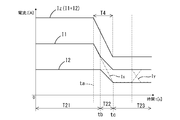
- the second power supply 106 can switch from the first control (constant current control) to the third control (current suppression control) in response to the detection of the “predetermined rising state”.
- the output voltage of the second power supply 106 is less than the first threshold value Vth1 before the time tb, and the output voltage of the second power supply 106 becomes the first at the time tb due to the sudden decrease in the load current in the period T4. It is 1 threshold Vth1 or more.
- the in-power supply control unit 32 controls the second power conversion unit 22 for the first control (constant current) as in the period T22.
- the output current value I2 is reduced by switching from the control) to the third control (current suppression control).
- the power conversion device 101 may output an excessive current from the second power supply 106 during the first control (constant current control) of the second power supply 106, and the output voltage may increase accordingly.
- the output current of the second power supply 106 can be rapidly reduced to recover the output voltage.
- the power conversion device 101 quickly suppresses the output current of the second power supply 106 according to the state in which the output voltage of the power supply system 100 is concerned to rise, and then the output voltage of the second power supply 106 becomes a predetermined value.
- the third control can be continued until (second threshold Vth2) is reached.
- the power conversion device 101 returns the second power supply 106 to the first control (constant current control) after confirming that the output voltage of the second power supply 106 has been suppressed to a predetermined value (second threshold value Vth2). be able to.
- the power conversion device 101 of the present disclosure can solve this problem as shown in FIG. The alternate long and short dash line Ix in FIG.
- FIG. 9 is a change in the output current value of the first power supply 104 when it is operated as shown in FIG. 8, and the alternate long and short dash line Iy in FIG. 9 is a change in the output current value when it is operated as shown in FIG. 2 It is a change in the output current value of the power supply 106.
- FIG. 10 is a graph when the current value I1 of the first power supply 104 becomes 0 due to a sudden decrease in the load current.
- FIG. 10 is a graph relating to the same apparatus as in FIG. 8, and is an example in which the current suppression control is not performed in the configuration shown in FIGS. 1 to 6.
- the load current suddenly decreases from the time ta, and the total current value Iz (the sum of the current value I1 of the first power supply 104 and the current value I2 of the second power supply 106) decreases sharply.
- the current limit value is changed from the time td according to the communication performed after the time ta, and the current value I2 of the second power supply 106 is reduced.
- the current value I1 of the first power supply 104 reaches 0 at time te as the load current suddenly decreases, and then is maintained at 0 from time te.
- a transient voltage rise occurs during the period T14 in which the output current of the first power supply 104 suddenly decreases due to the sudden decrease in the load current.
- the current value I1 of the first power supply 104 becomes 0, and the second power supply 106 is maintained in the constant voltage mode, so that the output voltage is constantly increased.
- the power conversion device 101 of the present disclosure as shown in FIG. 11, a sudden decrease in the load current similar to that in FIG. 10 occurs during the first control of the second power supply 106 (during the constant current control in the period T21). Also, the third control (current suppression control) can be performed from the time tb when the "predetermined rising state" occurs. As a result, the power conversion device 101 can reduce the output current value I2 from the time tb, and can suppress the transient voltage rise which is a concern in the period T4. Moreover, since the power conversion device 101 can suppress or prevent the current value I1 of the first power supply 104 from reaching 0, it also suppresses a steady increase in the output voltage as in the period T15 of FIG. Can be done.
- the alternate long and short dash line Ix in FIG. 11 is a change in the output current value of the first power supply 104 when it is operated as shown in FIG. 10, and the alternate long and short dash line Iy in FIG. 11 is the change in the output current value when it is operated as shown in FIG. 2 It is a change in the output current value of the power supply 106.
- the power conversion device 101 sets a current limit value based on a command value received by the receiving unit when performing the first control (constant current control). With such a configuration, if there is a concern that the output voltage will rise, if only the method of updating the current limit value based on the command value issued from the outside is adopted, the output voltage will rise. There is a concern that it may take some time before the current limit value is set according to the above. However, in the power conversion device 101, the second power supply 106 itself can switch to the third control (current suppression control) according to the situation where there is a concern that the output voltage will rise, so that the switching is caused by a communication delay or the like. Delays are less likely to occur.
- the second power supply 106 corresponds to the value of the output current of the first power supply 104 (first current value I1) based on the communication with the outside when the first control (constant current control) is performed.
- the current limit value can be set. That is, the power conversion device 101 can adjust the output current of the second power supply 106 by more accurately reflecting the first current value I1 during the first control (constant current control).
- the current setting value is updated according to the command value. Will maintain the previous "current limit value according to the first current value I1".
- this power conversion device 101 can quickly switch to the third control (current suppression control) by determining the situation in which the output voltage is concerned to rise by the second power supply 106 itself, it is caused by a communication delay or the like. Therefore, it is possible to suppress an excessive increase in the output voltage due to the delay in updating the current limit value.
- the in-power supply control unit 32 (drive unit) sets the ratio of the first current value I1 and the current limit value Itb to a predetermined ratio based on the first current value I1 during the first control (constant current control). Set the current limit value Itb to.
- This power conversion device makes it easy to keep the value I1 of the output current from the first power supply 104 and the value I2 of the output current from the second power supply at a predetermined ratio during the first control (constant current control). Then, when the output voltage of the power supply system 100 is in a state of concern during the first control (constant current control), the power conversion device 101 does not keep the output current at the predetermined ratio. Can be quickly prioritized to suppress.
- the second power supply 106 can set the current limit value Itb by communicating with the first power supply 104 during the first control (constant current control). Then, when the output voltage of the power supply system 100 is concerned about an increase during the first control (constant current control), the second power supply 106 suppresses the current by determining and driving the second power supply 106 itself. You can quickly switch to control.
- the power conversion device 101 is based on the detection value (first current value I1) actually detected by the first power supply 104 during the first control (constant current control), and is the value of the output current from the first power supply 104. It becomes easier to keep the value I1 and the value I2 of the output current from the second power source 106 more accurately at a predetermined ratio.
- the rated current value of the second power supply 106 is smaller than the rated current value of the first power supply 104.
- the power conversion device 101 can relatively suppress the rated current value of the second power supply 106, and can perform a characteristic operation by the second power supply 106 in which the rated current value is suppressed.
- the "predetermined rising state” is a state in which the output voltage of the second power supply 106 reaches the first threshold value Vth1 during the first control, but is not limited to this example.
- the "predetermined rising state” may be a state in which the rate of increase in the output voltage of the second power supply 106 reaches a certain value during the first control.
- the determination in step S2 of FIG. 7 performed by the in-power supply control unit 32 may be changed to the determination of "whether or not the rate of increase in the output voltage of the second power supply 106 is equal to or higher than a certain value".
- step S3 when it is determined in step S2 that the rate of increase in the output voltage of the second power source 106 is equal to or greater than a certain value, and when it is determined that the rate of increase is less than a certain value. May perform the process of step S4.
- the "predetermined rising state” is a state in which the output voltage of the second power supply 106 reaches the first threshold value Vth1 during the first control, but is not limited to this example.
- the "predetermined rising state” may be "switching from the constant current mode to the constant voltage mode during the first control (constant current control)". "Switching from constant current mode to constant voltage mode” means that the calculation result of the constant voltage mode calculation unit 32C is selected from the state in which the arbitration unit 32D selects the calculation result of the constant current mode calculation unit 32B. It has switched to the state. In this example, if the determination in step S2 of FIG.
- step S3 the process of step S3 may be performed, and if not, the process of step S4 may be performed. ..
- the "predetermined rising state” is a state in which the output voltage of the second power supply 106 reaches the first threshold value Vth1 during the first control (constant current control), but is not limited to this example.
- the "predetermined rising state” may be "switching from the constant current mode to the constant voltage mode during the first control (constant current control)".
- "Switching from constant current mode to constant voltage mode” means that the calculation result of the constant voltage mode calculation unit 32C is selected from the state in which the arbitration unit 32D selects the calculation result of the constant current mode calculation unit 32B. It has switched to the state. In this example, if the determination in step S2 of FIG.
- step S7 performed by the in-power supply control unit 32 is changed to the determination of "whether or not the constant current mode is switched to the constant voltage mode during the first control (constant current control)". good. Then, when it is determined in step S2 that the constant current mode is switched to the constant voltage mode, the in-power supply control unit 32 may perform the process of step S3, and if not, perform the process of step S4. ..
- step S5 of FIG. 7 may be changed to the determination of "whether or not the constant voltage mode has been switched to the constant current mode".
- switching from the constant voltage mode to the constant current mode means that the calculation result of the constant current mode calculation unit 32B is selected from the state in which the arbitration unit 32D selects the calculation result of the constant voltage mode calculation unit 32C. It is that it has switched to the state of being.
- the in-power supply control unit 32 determines in step S5 that the constant voltage mode has been switched to the constant current mode, the process of step S7 is performed, and if not, the process of step S6 is performed. good.
- the first power supply 104 transmits the current value I1 of the first power supply 104 to the second power supply 106 as a command value, and the second power supply 106 sets the current limit value based on this command value.
- the first power supply 104 calculates the current limit value Itb so that the current value I1 and the current limit value Itb are in a predetermined ratio based on its own current value I1, and the second power supply 104 uses this current limit value Itb as a command value. It may be transmitted to the power source 106.
- the control unit 108 may transmit the current value I1 of the first power supply 104 acquired from the first power supply 104 to the second power supply 106 as a command value.
- the control unit 108 calculates the current limit value Itb so that the current value I1 and the current limit value Itb become a predetermined ratio based on the current value I1, and transmits this current limit value Itb as a command value to the second power source. You may.
- the control unit 108 seconds the sum (total current value Iz) of the current value I1 of the first power supply 104 acquired from the first power supply 104 and the current value I2 of the second power supply 106 acquired from the second power supply 106. It may be transmitted to the power source 106.
- the control unit 108 may transmit the value of a predetermined ratio of the total current value Iz to the second power supply 106 as the current limit value Itb.
- the in-power supply control unit 32 sets the ratio of the first current value I1 and the current limit value Itb to a predetermined ratio based on the first current value I1 during the first control (constant current control).
- the current limit value Itb is set so as to be, but the present invention is not limited to this example.
- the in-power supply control unit 32 (drive unit) is based on the total current value Iz (I1 + I2) obtained from the control unit 108 for the ratio of the first current value I1 and the current limit value Itb during the first control (constant current control).
- the current limit value Itb may be set so as to be a predetermined ratio of the total current value Iz. In this case, the total current value Iz corresponds to an example of the command value.
- the control unit 108 continuously monitors the total current value Iz (the sum of the first current value I1 and the second current value I2), and updates the latest total current value Iz at short time intervals in the second power supply 106. You can send it to.
- the control unit 32 (driving unit) in the power supply is not limited to these examples, and the first current value I1 is used as a command value and the first current value I1 and the current limit value Itb are used as variables.
- the current limit value Itb may be determined according to the first current value I1 by using a predetermined calculation formula.
- the in-power supply control unit 32 uses a predetermined arithmetic expression in which the total current value Iz is a command value and the total current value Iz and the current limit value Itb are variables, and the total current value Iz is used.
- the current limit value Itb may be determined accordingly.
- the power conversion device 101 is a device including the control unit 108, but a device such as the control unit 108 that does not include control may be used as the power conversion device.
- the portion of the power conversion device 101 excluding the control unit 108 may be the power conversion device.
- the power conversion device 101 is a device including the first power supply 104, but a device not including the first power supply may be a power conversion device.
- the portion of the power converter 101 excluding the first power supply 104 may be the power converter, or the portion of the power converter 101 excluding the first power supply 104 and the control unit 108 may be the power converter. good.
- the isolated DCDC converter as shown in FIGS. 3 and 4 is exemplified as a specific configuration of the first power conversion unit 21 and the second power conversion unit 22, but the configurations other than those shown in FIGS. DCDC converter may be used.
- the power supply system 100 is mounted on a vehicle such as an electric vehicle, but the present invention is not limited to this.
- the power supply system 100 may be mounted on a vehicle of a type other than these, for example, a PHEV (Plug-in Hybrid Electric Vehicle) or a HEV (Hybrid Electric Vehicle), or may be mounted on a device other than the vehicle.
- a PHEV Plug-in Hybrid Electric Vehicle
- HEV Hybrid Electric Vehicle
Landscapes
- Engineering & Computer Science (AREA)
- Power Engineering (AREA)
- Transportation (AREA)
- Mechanical Engineering (AREA)
- Life Sciences & Earth Sciences (AREA)
- Sustainable Development (AREA)
- Sustainable Energy (AREA)
- Dc-Dc Converters (AREA)
- Charge And Discharge Circuits For Batteries Or The Like (AREA)
- Electric Propulsion And Braking For Vehicles (AREA)
Abstract
電力変換装置(101)は、第1電源(104)に対して並列に接続される第2電源(106)を備える。第2電源(106)の駆動部は、電流制限値に基づく定電流モードで電力変換部を動作させる第1制御と、定電流モードとは異なるモードで電力変換部を動作させる第2制御と、を切り替える。駆動部は、第1制御中に第2電源(106)の出力電圧が所定の上昇状態となった場合又は定電流モードを解除する解除条件が成立した場合に、電流制限値よりも低い電流を電力変換部に出力させる第3制御を行う。
Description
本開示は、電力変換装置に関する。
電気自動車等においては、高電圧バッテリ(例えば、直流300V)の電圧をDC-DCコンバータにより低電圧(例えば、直流14V)に変換して負荷に供給する技術が採用されている。この種の電力変換装置では、電力供給先の負荷の必要電流が大きい場合、1つのDC-DCコンバータでは電流容量が不足してしまうことがある。その対策として、例えば、複数のDC-DCコンバータを並列接続して使用することが考えられる。特許文献1には、その一例が開示されている。
本願の発明者は、複数の電源を並列に接続した電源システムとして、定電圧を出力する第1電源と定電流を出力する第2電源とを並列に接続した電源システムを想定した。この電源システムは、負荷電流の急低下などによって第1電源の出力電流が低下又は停止した場合などにおいて第2電源の出力電圧が電源システムの目標電圧を超えて上昇してしまう懸念がある。このような電圧上昇を抑えるためには、定電流制御を行うための電流制限値をより小さい値に速やかに変更する必要がある。しかし、通信によって電流制限値を変更する指令を与える方法では、指令の送信、指令の受信、電流制限値の演算、電流制限値の再設定などを全て行う過程で時間がかかるため、第2電源の出力電流を迅速に抑制することはできない。
本開示は、定電圧を出力する第1電源に対して第2電源が並列に接続された電源システムにおいて、第2電源の定電流動作中に電源システムの出力電圧が上昇する場合に第2電源の出力電流を迅速に抑制することを目的の一つとする。
本開示の一つである電力変換装置は、
第1目標電圧に基づいて定電圧を出力する第1電源を備え且つ前記第1電源が第1導電路と第2導電路との間で電力変換を行う電源システムに用いられる電力変換装置であって、
前記第1導電路と前記第2導電路との間において前記第1電源に対して並列に接続される第2電源を備え、
前記第2電源は、前記第1導電路と前記第2導電路との間で電力変換を行う電力変換部と、前記電力変換部を駆動する駆動部と、を有し、
前記駆動部は、電流制限値に基づく定電流モードで前記電力変換部を動作させる第1制御と、前記定電流モードとは異なるモードで前記電力変換部を動作させる第2制御と、を切り替え、
前記駆動部は、前記第1制御中に前記第2電源の出力電圧が所定の上昇状態となった場合又は前記定電流モードを解除する解除条件が成立した場合に、前記電流制限値よりも低い電流を前記電力変換部に出力させる第3制御を行う。
第1目標電圧に基づいて定電圧を出力する第1電源を備え且つ前記第1電源が第1導電路と第2導電路との間で電力変換を行う電源システムに用いられる電力変換装置であって、
前記第1導電路と前記第2導電路との間において前記第1電源に対して並列に接続される第2電源を備え、
前記第2電源は、前記第1導電路と前記第2導電路との間で電力変換を行う電力変換部と、前記電力変換部を駆動する駆動部と、を有し、
前記駆動部は、電流制限値に基づく定電流モードで前記電力変換部を動作させる第1制御と、前記定電流モードとは異なるモードで前記電力変換部を動作させる第2制御と、を切り替え、
前記駆動部は、前記第1制御中に前記第2電源の出力電圧が所定の上昇状態となった場合又は前記定電流モードを解除する解除条件が成立した場合に、前記電流制限値よりも低い電流を前記電力変換部に出力させる第3制御を行う。
本開示の一つである電力変換装置は、定電圧を出力する第1電源に対して第2電源が並列に接続された電源システムにおいて、第2電源の定電流動作中に電源システムの出力電圧が上昇する場合に第2電源の出力電流を迅速に抑制することができる。
以下では、本開示の実施形態が列記されて例示される。なお、以下で例示される〔1〕~〔12〕の特徴は、矛盾しない範囲でどのように組み合わされてもよい。
〔1〕第1目標電圧に基づいて定電圧を出力する第1電源を備え且つ前記第1電源が第1導電路と第2導電路との間で電力変換を行う電源システムに用いられる電力変換装置であって、前記第1導電路と前記第2導電路との間において前記第1電源に対して並列に接続される第2電源を備え、前記第2電源は、前記第1導電路と前記第2導電路との間で電力変換を行う電力変換部と、前記電力変換部を駆動する駆動部と、を有し、前記駆動部は、電流制限値に基づく定電流モードで前記電力変換部を動作させる第1制御と、前記定電流モードとは異なるモードで前記電力変換部を動作させる第2制御と、を切り替え、前記駆動部は、前記第1制御中に前記第2電源の出力電圧が所定の上昇状態となった場合又は前記定電流モードを解除する解除条件が成立した場合に、前記電流制限値よりも低い電流を前記電力変換部に出力させる第3制御を行う電力変換装置。
上記〔1〕の電力変換装置は、定電圧を出力する第1電源に対して第2電源が並列に接続された電源システムにおいて、第2電源が定電流動作を行うことを可能とする。更に、上記の電力変換装置は、第2電源の第1制御(定電流モードで動作させる制御)中に電源システムの出力電圧が実際に「所定の上昇状態」となるまで上昇した場合に第2電源自身が迅速に第3制御(電流を抑制する制御)に切り替わり得る。或いは、上記の電力変換装置は、第2電源の第1制御(定電流モードで動作させる制御)中に定電流モードの解除条件が成立して電源システムの出力電圧が上昇し得る状態となった場合に第2電源自身が迅速に第3制御(電流を抑制する制御)に切り替わり得る。つまり、この電力変換装置は、第2電源の第1制御(定電流モードで動作させる制御)中に電源システムの出力電圧の上昇が懸念される状態となっても第2電源の出力電流を抑制する第3制御に迅速に移行し、電源システムの出力電圧の上昇を迅速に抑え得る。
〔2〕前記所定の上昇状態は、前記第1制御中に前記第2電源の出力電圧が閾値に達した状態である〔1〕に記載の電力変換装置。
上記〔2〕の電力変換装置は、第2電源の第1制御(定電流モードで動作させる制御)中に電源システムの出力電圧が上昇したか否かを判断し得る構成を、より簡易に実現することができる。
〔3〕前記所定の上昇状態は、前記第1制御中に前記第2電源の出力電圧の増加率が一定値に達した状態である〔1〕に記載の電力変換装置。
上記〔3〕の電力変換装置は、第2電源の第1制御(定電流モードで動作させる制御)中に電源システムの出力電圧が所定の上昇度合いを超えて急上昇したか否かをより正確に判断し得る。上記電力変換装置は、出力電圧をモニタする周期及び出力電圧と閾値とを比較する周期が短いほど応答性が高くなり有利になる。
〔4〕前記第2制御は、前記第1目標電圧よりも高い第2目標電圧に基づく定電圧モードで前記電力変換部を動作させる制御であり、前記駆動部は、切替条件が成立した場合に前記定電流モードから前記定電圧モードに切り替わり、前記駆動部は、前記第1制御中に前記定電流モードから前記定電圧モードに切り替わった場合に前記第3制御を行う〔1〕に記載の電力変換装置。
上記〔4〕の電力変換装置は、第2電源の第1制御(定電流モードで動作させる制御)中に定電圧モードに切り替わって相対的に高い第2目標電圧を出力させる定電圧制御が始まった場合に、第3制御に迅速に移行することができる。上記電力変換装置は、いずれのモードを採用するかを判定する演算周期がより短いほど、応答性が高くなり有利になる。
〔5〕前記駆動部は、前記第3制御中に前記第2電源の出力電圧が前記所定の上昇状態のときよりも低い所定値に低下した場合に前記第1制御を行う〔2〕から〔4〕のいずれか一つに記載の電力変換装置。
上記〔5〕の電力変換装置は、電源システムの出力電圧の上昇が懸念される状態に応じて第2電源の出力電流を迅速に抑制した後、第2電源の出力電圧が所定値に達するまで第3制御(電流抑制制御)を続けることができる。そして、この電力変換装置は、第2電源の出力電圧が所定値まで抑えられたことを確認してから、第2電源を第1制御(定電流制御)に戻すことができる。
〔6〕前記第2電源は、第2切替条件が成立した場合に前記定電圧モードから前記定電流モードに切り替わり、前記駆動部は、前記第3制御中に前記定電圧モードから前記定電流モードに切り替わった場合に前記第1制御を行う〔4〕に記載の電力変換装置。
上記〔6〕の電力変換装置は、第2電源の第3制御(電流抑制制御)中に定電圧モードから定電流モードに切り替わった場合に、即ち、相対的に高い第2目標電圧を出力する状況が解消された場合に、迅速に第3制御を解除して第1制御に移行することができる。上記電力変換装置は、いずれのモードを採用するかを判定する演算周期がより短いほど、応答性が高くなり有利になる。
〔7〕前記第2電源は、前記第2電源の外部の装置から指令値を受信する受信部を有し、前記駆動部は、前記第1制御を行う場合に前記受信部が受信した前記指令値に基づいて前記電流制限値を設定する〔1〕から〔6〕のいずれか一つに記載の電力変換装置。
上記〔7〕の電力変換装置は、第1制御(定電流制御)を行う場合に受信部が受信した指令値に基づいて電流制限値を設定する。このような構成のものでは、仮に、出力電圧の上昇が懸念される状況となった場合に、外部から発せられる指令値に基づいて電流制限値を更新する方法のみを採用すると、出力電圧の上昇に応じた電流制限値に設定されるまでに時間がかかる懸念がある。しかし、上記の電力変換装置は、出力電圧の上昇が懸念される状況に応じて第2電源自身が第3制御(電流抑制制御)に切り替えることができるため、通信の遅延等に起因する切り替わりの遅れが生じにくくなる。
〔8〕前記指令値は、前記電源システムが供給する総電流値又は前記第1電源が供給する第1電流の値に応じた値であり、前記駆動部は、前記第1制御を行う場合に前記指令値に基づいて前記総電流値又は前記第1電流の値に応じた前記電流制限値を設定する〔7〕に記載の電力変換装置。
上記〔8〕の電力変換装置では、第2電源は、第1制御(定電流制御)を行う場合に外部との通信に基づいて総電流値又は第1電流の値に応じた電流制限値を設定することができる。つまり、上記の電力変換装置は、第1制御(定電流制御)中には上記総電流値又は上記第1電流の値をより正確に反映して第2電源の出力電流を調整することができる。但し、この電力変換装置は、出力電圧の上昇が懸念される状況となった場合、この状況に応じた新たな指令値が通信によって送信され、この指令値に応じた電流設定値に更新されるまでは、前回の「総電流値又は第1電流の値に応じた電流制限値」が維持されてしまう。つまり、この電力変換装置は、何も対策を講じないと、出力電圧の上昇が懸念される状況となってから第2電源の出力電流が実際に抑制されるまでに時間がかかってしまう懸念がある。しかし、上記の電力変換装置は、出力電圧の上昇が懸念される状況を第2電源自身が判断して第3制御(電流抑制制御)に迅速に切り替えることができるため、通信の遅延等に起因して電流制限値の更新が遅れることによる出力電圧の過度な上昇を抑え得る。
〔9〕前記駆動部は、前記第1制御中に前記第1電流の値と前記電流制限値との割合を前記総電流値又は前記第1電流の値に基づいて所定割合にするように前記電流制限値を設定する〔8〕に記載の電力変換装置。
上記〔9〕の電力変換装置は、第1制御(定電流制御)中には第1電源からの出力電流の値と第2電源からの出力電流の値とを所定割合に保ちやすくなる。そして、第1制御(定電流制御)中に出力電圧の上昇が懸念される状態になった場合には、上記電力変換装置は、上記所定割合に保ち続けることよりも出力電流を抑制することを迅速に優先させることができる。
〔10〕前記第1電源と、前記第1電源及び前記第2電源を制御する制御部と、を含み、前記第1電源又は前記制御部が前記指令値を送信する〔7〕から〔9〕のいずれか一つに記載の電力変換装置。
上記〔10〕の電力変換装置では、第2電源は、第1制御(定電流制御)中には制御部又は第1電源との通信によって電流制限値を設定することができる。そして、第1制御(定電流制御)中に出力電圧の上昇が懸念される状態になった場合には、第2電源は、第2電源自身の判定及び駆動によって電流を抑制する制御に迅速に切り替えることができる。
〔11〕前記第1電源を含み、前記第1電源は、前記第1導電路と前記第2導電路との間で電力変換を行う第1電力変換部と、前記第1電力変換部を駆動する第1駆動部と、前記第1電力変換部から出力される出力電流の値を検出する検出部と、前記出力電流の値を特定する情報を送信する送信部と、を含み、前記第2電源は、第2電力変換部である前記電力変換部と、第2駆動部である前記駆動部と、を含み、前記受信部は少なくとも前記出力電流の値を特定する情報を受信し、前記駆動部は、前記第1制御中に前記第1電流の値と前記電流制限値との割合を前記特定する情報に基づいて前記所定割合にするように前記電流制限値を設定する〔10〕に記載の電力変換装置。
上記〔11〕の電力変換装置は、第1制御(定電流制御)中には第1電源で実際に検出された検出値に基づき、第1電源からの出力電流の値と第2電源からの出力電流の値とをより正確に所定割合に保ちやすくなる。
〔12〕前記第1電源の定格電流値よりも前記第2電源の定格電流値のほうが小さい〔1〕から〔11〕のいずれか一つに記載の電力変換装置。
上記〔12〕の電力変換装置は、第2電源の定格電流値を相対的に抑えることができ、定格電流値の抑えられた第2電源によって特徴的な動作を行うことができる。
<第1実施形態>
1.全体構成
図1で示される第1実施形態に係る車載用の電源システム100は、例えば電気自動車等の車両に搭載される車載用の直流電圧供給システムとして機能し得る。電源システム100は、負荷110に直流電圧を供給し得る。電源システム100は、電力変換装置101とバッテリ102とを備える。
1.全体構成
図1で示される第1実施形態に係る車載用の電源システム100は、例えば電気自動車等の車両に搭載される車載用の直流電圧供給システムとして機能し得る。電源システム100は、負荷110に直流電圧を供給し得る。電源システム100は、電力変換装置101とバッテリ102とを備える。
負荷110は、車両に搭載される電気機器であればよく、例えば、エンジンやモータを稼動するのに必要な付属機器(セルモータ、オルタネータ及びラジエータクーリングファン等)であってもよい。負荷110の種類は限定されず、電動パワーステアリングシステム、電動パーキングブレーキ、照明、ワイパー駆動部、ナビゲーション装置等を含んでいてもよい。
バッテリ102は、例えば高電圧(例えば300V)を供給するバッテリ(例えば2次電池)である。バッテリ102における高電位側の正極端子は、第1導電路11に電気的に接続されている。バッテリ102における低電位側の負極端子は、図示されていないグラウンドに電気的に接続されている。
電力変換装置101は、第1導電路11と第2導電路12との間で電力変換を行う装置である。電力変換装置101は、主に、第1電源104と第2電源106と制御部108とを備える。第1電源104及び第2電源106は、第1導電路11と第2導電路12との間に並列に接続されている。図2のように、第1電力変換部21及び第2電力変換部22が第1導電路11と第2導電路12との間に並列に接続されている。電力変換装置101は、バッテリ102から第1導電路11を介して入力される入力電圧を降圧し、第2導電路12に対して第1導電路11の電圧よりも低い出力電圧を印加する動作を行い得る。
なお、本明細書において、特別な説明が無い限り、電圧とはグラウンドとの電位差を意味する。例えば、第1導電路11の電圧は、第1導電路11とグラウンドとの電位差を意味し、第2導電路12の電圧は、第2導電路12とグラウンドとの電位差を意味する。
第1電源104及び第2電源106は、いずれもDC-DCコンバータとして機能する。第1電源104及び第2電源106はそれぞれ、バッテリ102から入力される直流電圧VHを所定の出力電圧V1及びV2にそれぞれ変換して、各々の出力端子から出力する。
第1電源104は、第1導電路11と第2導電路12との間に設けられ、第2導電路に定電圧を出力するように電力変換を行い得る装置である。図2に示されるように、第1電源104は、電力変換を行う第1電力変換部21と、第1電力変換部21を駆動する電源内制御部31と、インタフェース部61と、第1電圧値検出部41と、第1電流値検出部51と、を有する。電源内制御部31は、第1電力変換部21を駆動する第1駆動部の一例に相当する。以下の説明では、インタフェース部61は、IF部61とも称される。
第1電力変換部21は、第1導電路11と第2導電路12との間で電力変換を行う装置であり、具体的には、第1導電路11から第1入力路71を介して入力される電力を変換し、第1出力路81を介して第2導電路12に電力を出力する動作を行う。第1入力路71は、第1導電路11から分岐した導電路であり、一端が第1導電路11に電気的に接続され、他端が第1電力変換部21に電気的に接続される。第1出力路81は、一端が第1電力変換部21に電気的に接続され、他端が第2導電路12に電気的に接続される。
第1電力変換部21は、例えば、図3のようなフルブリッジ方式の絶縁型のDCDCコンバータとして構成されている。図3では、第1電圧値検出部41や第1電流値検出部51などは省略されている。第1電力変換部21は、入力回路部21X、トランス部21Y、出力回路部21Zを有する。入力回路部21Xは、複数の半導体スイッチ素子21A,21B,21C,21Dと、コンデンサ21Eとを備え、トランス部21Yの一次側コイル21Fに電気的に接続される。入力回路部21Xは、複数の半導体スイッチ素子21A,21B,21C,21Dのスイッチング動作に応じて一次側コイル21Fに交流電圧を生じさせる。複数の半導体スイッチ素子21A,21B,21C,21Dのスイッチング動作の制御は電源内制御部31によって行われ、具体的には後述のCV(Constant Voltage)制御が行われる。出力回路部21Zは、ダイオード21J,21K、インダクタ21L、コンデンサ21Mを備え、トランス部21Yの二次側コイル21G,21Hに電気的に接続され、二次側コイル21G,21Hに印加される交流電圧を整流して直流電圧を出力する。第1電力変換部21は、半導体スイッチ素子21A,21B,21C,21Dのスイッチング動作によって電圧変換を行う。第1電力変換部21は、第1導電路11に印加された入力電圧VH(第1導電路11とグラウンド側の導電路13Aとの間の電位差)を降圧し、第1出力路81に出力電圧(第1出力路81とグラウンド側の導電路13Bとの間の電位差)を生じさせる。導電路13A,13Bは、例えば0V程度に維持される基準導電路である。
図2のように、第1電流値検出部51は、第1出力路81の途中に介在する。第1電流値検出部51は、第1出力路81を流れる電流の値(第1電流値I1)を検出し、第1電流値I1を示す信号を電源内制御部31に入力する。第1電力変換部21が電力変換動作(具体的には降圧動作)を行う場合、第1電流値検出部51は、第1電力変換部21が第1出力路81を介して出力する出力電流の値を第1電流値I1として検出する。この例では、第1電流値検出部51が検出部の一例に相当し、第1電力変換部21から出力される出力電流の値(第1電流値I1)を検出する。
第1電圧値検出部41は、第1出力路81の電圧値(第1電圧値V1)を検出し、電源内制御部31に第1電圧値V1を示す信号を入力する。第1電力変換部21が電力変換動作を行う場合、第1電圧値検出部41は、第1電力変換部21が第1出力路81に印加する出力電圧の値を第1電圧値V1として検出し、この出力電圧を示す信号を電源内制御部31に入力する。
IF部61は、制御部108から伝送されるデータを受信し、電源内制御部31に入力する。更に、IF部61は、電源内制御部31と協働し、電源内制御部31が取得した第1電流値I1、第1電圧値V1を制御部108に送信し得る。IF部61は、送信部の一例に相当し、第1電力変換部21が出力する出力電流の値(第1電流値I1)を特定する情報を送信する機能を有する。この例では、出力電流の値(第1電流値I1)を特定する情報が指令値の一例に相当する。出力電流の値(第1電流値I1)を特定する情報は、出力電流の値(第1電流値I1)そのものであってもよく、出力電流の値(第1電流値I1)に一定値を加算した値であってもよく、出力電流の値(第1電流値I1)に一定係数を乗算した値であってもよい。
電源内制御部31は、情報処理機能を有する制御装置として構成され、例えば、内部メモリを含むマイクロコンピュータによって構成されている。内部メモリには、電源内制御部31が実行すべきプログラム及び必要なパラメータ等が記憶されている。電源内制御部31は、IF部61から受信したデータに基づき、第1電力変換部21を制御し得る。例えば、電源内制御部31は、第1電力変換部21の動作に必要な設定値を算出し、第1電力変換部21に設定する。
本構成では、制御部108は、第1電源104に対して一定の出力電圧目標値を与えるように動作する。以下の説明では、制御部108が第1電源104に与える出力電圧目標値は「第1目標電圧」とも称される。また、以下の説明では、上記のCV制御によって一定の目標電圧を出力するモードは、定電圧モードとも称される。
第1電源104は、制御部108から上記第1目標電圧が与えられた場合、第1出力路81の電圧を上記第1目標電圧とするように電圧変換動作(降圧動作)を行い得る。具体的には、電源内制御部31は、第1出力路81に上記第1目標電圧を出力させるように第1電力変換部21を駆動する。第1電力変換部21は、電源内制御部31による駆動(上記CV制御)によって定電圧モードで動作し、バッテリ102から入力される直流電圧VHを降圧し、第1出力路81の電圧を上記第1目標電圧とするように電圧変換動作を行い得る。
具体的には、電源内制御部31が周期的にフィードバック演算を行い、半導体スイッチ素子21A,21B,21C,21Dに与えるPWM信号のデューティを更新する。電源内制御部31は、各周期のフィードバック演算において、上記第1目標電圧と第1電圧値検出部41によって検出される第1電圧値V1(第1出力路81の電圧)との偏差を算出する。そして、電源内制御部31は、各周期のフィードバック演算において、その偏差と予め定められたゲインとに基づいてPI演算式又はPID演算式によって第1出力路81の電圧を第1目標電圧に近づけるための操作量(デューティの増減量)を決定する。そして、電源内制御部31は、このように決定された操作量(デューティの増減量)を現在の制御量(変更前のデューティ)に加えて新たなデューティを算出する。このように、電源内制御部31は、各周期のフィードバック演算により各周期においてPWM信号のデューティを更新し得る。
第2電源106は、第1導電路11と第2導電路12との間で電力変換を行い得る装置である。図2に示されるように、第2電源106は、電力変換を行う第2電力変換部22と、第2電力変換部22を駆動する電源内制御部32と、インタフェース部62と、第2電圧値検出部42と、第2電流値検出部52と、を有する。第2電力変換部22は、電力変換部の一例に相当する。電源内制御部32は、駆動部の一例に相当し、第2駆動部の一例に相当する。以下の説明では、インタフェース部62は、IF部62とも称される。
第2電力変換部22は、第1電力変換部21に対して並列に接続され、第1導電路11から第2入力路72を介して入力される電力を変換し、第2出力路82を介して第2導電路12に電力を出力する動作を行う。第2入力路72は、第1導電路11から分岐した導電路であり、一端が第1導電路11に電気的に接続され、他端が第2電力変換部22に電気的に接続される。第2出力路82は、一端が第2電力変換部22に電気的に接続され、他端が第2導電路12に電気的に接続される。
図4で示されるように、第2電力変換部22は、図3で示される第1電力変換部21と同様のフルブリッジ方式の絶縁型のDCDCコンバータとして構成されている。図4では、第2電圧値検出部42や第2電流値検出部52などは図示が省略されている。第2電力変換部22は、入力回路部22X、トランス部22Y、出力回路部22Zを有する。入力回路部22Xは、複数の半導体スイッチ素子22A,22B,22C,22Dと、コンデンサ22Eとを備え、トランス部22Yの一次側コイル22Fに電気的に接続される。入力回路部22Xは、複数の半導体スイッチ素子22A,22B,22C,22Dのスイッチング動作に応じて一次側コイル22Fに交流電圧を生じさせる。複数の半導体スイッチ素子22A,22B,22C,22Dのスイッチング動作の制御は電源内制御部32によって行われ、具体的にはCVCC(Constant Voltage Constant Current)制御が行われる。出力回路部22Zは、ダイオード22J,22K、インダクタ22L、コンデンサ22Mを備え、トランス部22Yの二次側コイル22G,22Hに電気的に接続され、二次側コイル22G,22Hに印加される交流電圧を整流して直流電圧を出力する。第2電力変換部22は、半導体スイッチ素子22A,22B,22C,22Dのスイッチング動作によって電圧変換を行う。第2電力変換部22は、第1導電路11に印加された入力電圧VH(第1導電路11とグラウンド側の導電路13Cとの間の電位差)を降圧し、第2出力路82に出力電圧(第2出力路82とグラウンド側の導電路13Dとの間の電位差)を生じさせる。導電路13C,13Dは、例えば0V程度に維持される基準導電路である。
図2のように、第2電流値検出部52は、第2出力路82の途中に介在する。第2電流値検出部52は、第2出力路82を流れる電流の値(第2電流値I2)を検出し、第2電流値I2を示す信号を電源内制御部32に入力する。第2電力変換部22が電力変換動作(具体的には降圧動作)を行う場合、第2電流値検出部52は、第2電力変換部22が第2出力路82を介して出力する出力電流の値を第2電流値I2として検出する。
第2電圧値検出部42は、第2出力路82の電圧値(第2電圧値V2)を検出し、電源内制御部32に第2電圧値V2を示す信号を入力する。第2電力変換部22が電力変換動作を行う場合、第2電圧値検出部42は、第2電力変換部22が第2出力路82に印加する出力電圧の値を第2電圧値V2として検出し、この出力電圧を示す信号を電源内制御部32に入力する。
IF部62は、制御部108から伝送されるデータを受信し、電源内制御部32に入力する。更に、IF部62は、電源内制御部32と協働し、電源内制御部32が取得した第2電流値I2、第2電圧値V2を制御部108に送信し得る。IF部62は、受信部の一例に相当し、第2電源106の外部の装置から指令値を受信するように機能する。具体的には、IF62は、IF61が送信した情報(例えば、第1電力変換部21が出力する出力電流の値(第1電流値I1)を特定する情報)を受信する機能を有する。
電源内制御部32は、情報処理機能を有する制御装置として構成され、例えば、内部メモリを含むマイクロコンピュータによって構成されている。内部メモリには、電源内制御部32が実行すべきプログラム及び必要なパラメータ等が記憶されている。電源内制御部32は、IF部62から受信したデータに基づき、第2電力変換部22を制御し得る。例えば、電源内制御部32は、第2電力変換部22の動作に必要な設定値を算出し、第2電力変換部22に設定する。
本構成では、制御部108又は第1電源104は、第2電源106に対して出力電圧目標値又は出力電圧目標値を決定するための値を与えるように動作する。以下の説明では、第2電源106の出力電圧目標値は「第2目標電圧」とも称される。第2目標電圧は、例えば、第1目標電圧よりも少し高い値とされる。第2目標電圧は、制御部108又は第1電源104から第2電源106に直接与えられてもよい。或いは、制御部108又は第1電源104から第2電源106に第1目標電圧が与えられ、第2電源106が第1目標電圧よりも一定レベル高い電圧を第2目標電圧が設定してもよい。
更に、制御部108又は第1電源104は、第2電源106に対して電流制限値又は電流制限値を決定するための値を与えるように動作する。電流制限値は、制御部108又は第1電源104から第2電源106に直接与えられてもよく、制御部108から第2電源106に負荷電流値が与えられ、第2電源106が負荷電流値の一定割合の電流値を電流制限値としてもよい。この場合の負荷電流値は、電源システム100から負荷110に供給する電流値である。或いは、第1電源104から第2電源106に対して第1電流値I1が与えられ、第2電源106が第1電流値I1に基づいて電流制限値を設定してもよい。
本構成では、電源内制御部32(駆動部)が、第1制御(定電流制御)を行う場合にIF部62(受信部)が受信した指令値に基づいて電流制限値を指令値に応じた値(例えば、第1電流値I1に応じた値)に設定する。なお、以下で説明される代表例は、第1電源104から第2電源106に対して第1電流値I1が与えられ、第2電源106がこの第1電流値I1に基づいて第1電流値I1と電流制限値との割合を所定割合にするように電流制限値を設定する例である。具体的には、電源内制御部32(駆動部)が、定電流制御中に第1電流値I1と電流制限値との割合をIF部62(受信部)がIF部61から受信した情報(第1電流値I1を特定する情報)に基づいて所定割合にするように電流制限値を設定する。
第2電源106は、上記第2目標電圧及び上記電流制限値に基づき、CVCC制御により動作する。第2電源106は、上述のCV制御により、指定された一定電圧(第2目標電圧)を出力する定電圧モードでも動作することができる。第2電源106が行うCV制御は第2制御の一例に相当する。また、第2電源106は、CC(Constant Current)制御により、指定された一定電流値(上記電流制限値)を出力するように動作することもできる。第2電源106が行うCC制御は第1制御の一例に相当する。以下の説明では、指定された一定電流値を出力するモードは定電流モードとも称される。つまり、第2電源106は、定電圧モードでの動作と定電流モードとを切り替えて動作し得る。
図5は、電源内制御部32が実行する機能をブロックによって概念的に示す機能ブロック図である。図5における目標値設定部32A、定電流モード演算部32B、定電圧モード演算部32C、調停部32D、PWM信号生成部32Eの各機能は、マイクロコンピュータ等によってソフトウエア的に実現されてもよく、ハードウェア回路によって実現されてもよい。目標値設定部32Aは、インタフェース部62からの情報に基づき、電流制限値Itbを定電流モード演算部32Bに与え、第2目標電圧Vtbを定電圧モード演算部32Cに与える。
第2電力変換部22は、定電流モードで動作する場合、即ち電源内制御部32によって第1制御(定電流制御)が行われる場合、バッテリ102から入力される直流電圧VHを降圧し、第2出力路82の電流を上記電流制限値とする電圧変換動作を行う。電源内制御部32は、第2電力変換部22を定電流モードで動作させるためのフィードバック演算を所定の演算周期で周期的に行い得る。具体的には、定電流モード演算部32Bが上記演算周期で周期的にフィードバック演算を行い、操作量(第2出力路82の電流値を電流制限値に近づけるための新たなデューティ)を算出する。定電流モード演算部32Bは、各周期のフィードバック演算において、演算を行う周期における上記電流制限値Itbと第2電流値検出部52によって検出される第2電流値I2(第2出力路82の電流値)との偏差を算出する。そして、定電流モード演算部32Bは、演算を行う周期において、当該周期の上記偏差と予め定められたゲインとに予め定められた演算式とによって第2出力路82の電流値を上記電流制限値Itbに近づけるための操作量(新たなデューティ)を決定する。上記演算式は、PI(Proportional-Integral)演算式であってもよく、PID(Proportional-Integral-Differential)演算式であってもよい。例えば、定電流モード演算部32Bは、PI演算式によって操作量(新たなデューティ)を算出する場合、上記偏差と予め定められた比例ゲイン及び積分ゲインとに基づいてPI演算式によって操作量(新たなデューティ)を算出する。この操作量は、演算を行った周期のフィードバック演算結果であり、定電流モードの場合に現在のデューティから変化させるべき新たなデューティである。
第2電力変換部22は、定電圧モードで動作する場合、即ち電源内制御部32によって第2制御(定電圧制御)が行われる場合、バッテリ102から入力される直流電圧VHを降圧し、第2出力路82の電圧を上記第2目標電圧とする電圧変換動作を行う。電源内制御部32は、第2電力変換部22を定電圧モードで動作させるためのフィードバック演算を上記演算周期で周期的に行う。具体的には、定電圧モード演算部32Cが上記演算周期で周期的にフィードバック演算を行い、操作量(第2出力路の電圧値を第2目標電圧に近づけるための新たなデューティ)を算出する。定電圧モード演算部32Cは、各周期のフィードバック演算において、演算を行う周期における上記第2目標電圧Vtbと第2電圧値検出部42によって検出される第2電圧値V2(第2出力路82の電圧)との偏差を算出する。そして、定電圧モード演算部32Cは、演算を行う周期において、当該周期の上記偏差と予め定められたゲインとに基づいてPI演算式又はPID演算式によって第2出力路82の電圧を第2目標電圧Vtbに近づけるための操作量を決定する。例えば、定電圧モード演算部32Cは、PI演算式によって操作量(新たなデューティ)を算出する場合、上記偏差と予め定められた比例ゲイン及び積分ゲインとに基づいてPI演算式によって操作量(新たなデューティ)を算出する。この操作量は、演算を行った周期のフィードバック演算結果であり、定電圧モードの場合に現在のデューティから変化させるべき新たなデューティである。
調停部32Dは、定電流モード演算部32Bによって算出された操作量(デューティ)と定電圧モード演算部32Cによって算出された操作量(デューティ)のうちのいずれを選択するかを、予め定められた選択方式によって決定する。以下で説明される代表例では、定電流モード演算部32B及び定電圧モード演算部32Cによって算出された両操作量のうち小さい操作量(デューティ比が小さくなる演算結果)を選択する方法が採用される。本明細書において、切替条件が成立した場合とは、調停部32Dが、定電流モード演算部32Bが算出した操作量を選択している状態から定電圧モード演算部32Cが算出した操作量を選択する状態に切り替わった場合である。また、第2切替条件が成立した場合とは、調停部32Dが、定電圧モード演算部32Cが算出した操作量を選択している状態から定電流モード演算部32Bが算出した操作量を選択する状態に切り替わった場合である。なお、調停方法はこの決定方法に限定されず、他の決定方法が採用されてもよい。本開示では、第3制御(電流抑制制御)が行われていない期間(通信に基づく通常制御が行われている期間)において定電流モード演算部32Bが算出した操作量を調停部32Dが選択する場合の制御が第1制御(定電流制御)である。また、第3制御(電流抑制制御)が行われていない期間(通信に基づく通常制御が行われている期間)において定電圧モード演算部32Cが算出した操作量を調停部32Dが選択する場合の制御が第2制御(定電圧制御)である。このように電源内制御部32(駆動部)は、電流制限値に基づく定電流モードで第2電力変換部22(電力変換部)を動作させる第1制御と、定電流モードとは異なるモードで第2電力変換部22を動作させる第2制御と、を切り替える。
調停部32Dは、定電流モード演算部32Bによって算出された操作量(デューティ)と定電圧モード演算部32Cによって算出された操作量(デューティ)のうちの小さい操作量を選択する。そして、PWM信号生成部32Eは、調停部32Dで選択された操作量(デューティ)のPWM信号を、例えば、この操作量が決定された演算周期の次の周期のPWM信号として出力する。
このような動作がなされるため、電源内制御部32では、定電流モード演算部32Bが算出した操作量が調停部32Dによって採用される期間は、第2電力変換部22を定電流モードで動作させる定電流制御が継続する。また、電源内制御部32では、定電圧モード演算部32Cが算出する操作量が調停部32Dによって採用される期間は、第2電力変換部22を定電圧モードで動作させる定電圧制御が継続する。
図6に示されるように、制御部108は、CPU(Central Processing Unit)120、メモリ122、インタフェース部(以下、IF部という)124及びバス126を含む。制御部108における各部の間のデータ伝送は、バス126を介して行われる。メモリ122は、1以上の記憶媒体を有し、例えば、書換可能な半導体不揮発性メモリ等を含む。メモリ122には、CPU120が実行するプログラム及び所定のパラメータ等が記憶されている。メモリ122の一部の領域は、CPU120がプログラムを実行するときにワークエリアとして使用される。制御部108は、例えば、電気自動車等のECU(Electronic Control Unit)である。
CPU120は、第1電源104及び第2電源106の動作を制御する機能を有し、第1電源104に指示を与えることで第1電力変換部21を制御し、第2電源106に指示を与えることで第2電力変換部22を制御する。具体的には、CPU120は、IF部124を介して第1電源104に対して、第1目標電圧を伝送する。第1電源104は、上記第1目標電圧に基づいて定電圧モードで動作しうるようになっており、第1目標電圧に等しい電圧を出力するように動作する。また、CPU120は、IF部124を介して第2電源106に対して、第1目標電圧又は第2目標電圧、及び、負荷電流値又は電流制限値を伝送してもよい。第2電源106は、定電流モードで動作するときには上記電流制限値に等しい電流を出力するように動作し、定電圧モードで動作するときには上記第2目標電圧に等しい電圧を出力するように動作する。
2.電力変換制御
次の説明は、第2電源106が行う電力変換制御に関する。
図7の制御は、所定の開始条件が成立した後に第2電源106(具体的には電源内制御部32)が繰り返し実行する制御である。所定の開始条件は、例えば、車両が始動状態となった場合、電源内制御部32に対して電力供給が開始された場合、その他の開始条件が成立した場合などである。なお、第2電源106は、上記開始条件が成立した直後の初期動作として通信に基づく通常制御を開始するようになっている。通信に基づく通常制御は、通信で得られる上述の指令値(例えば第1電流値I1)に基づいて電流制限値Itbを設定した上で定電流モード演算部32B及び定電圧モード演算部32Cが演算を行い、調停部32Dが上述の調停によって操作量を決定する制御である。通信に基づく通常制御は、上述の第1制御(定電流制御)又は第2制御(定電圧制御)のいずれかである。通信に基づく通常制御では、調停部32Dが決定した操作量(デューティ)のPWM信号をPWM信号生成部32Eが出力する。なお、通信に基づく通常制御が行われている場合、定電流モード演算部32Bが算出した操作量を調停部32Dが採用し続ける期間は、第2電力変換部22を定電流モードで動作させる第1制御(定電流制御)が継続する。なお、電源内制御部32は、第1電源104の出力電圧が第1目標電圧であり且つ第2電源106の出力電流が電流制限値である限り、通信に基づく通常制御として上述の第1制御(定電流制御)を行う。
次の説明は、第2電源106が行う電力変換制御に関する。
図7の制御は、所定の開始条件が成立した後に第2電源106(具体的には電源内制御部32)が繰り返し実行する制御である。所定の開始条件は、例えば、車両が始動状態となった場合、電源内制御部32に対して電力供給が開始された場合、その他の開始条件が成立した場合などである。なお、第2電源106は、上記開始条件が成立した直後の初期動作として通信に基づく通常制御を開始するようになっている。通信に基づく通常制御は、通信で得られる上述の指令値(例えば第1電流値I1)に基づいて電流制限値Itbを設定した上で定電流モード演算部32B及び定電圧モード演算部32Cが演算を行い、調停部32Dが上述の調停によって操作量を決定する制御である。通信に基づく通常制御は、上述の第1制御(定電流制御)又は第2制御(定電圧制御)のいずれかである。通信に基づく通常制御では、調停部32Dが決定した操作量(デューティ)のPWM信号をPWM信号生成部32Eが出力する。なお、通信に基づく通常制御が行われている場合、定電流モード演算部32Bが算出した操作量を調停部32Dが採用し続ける期間は、第2電力変換部22を定電流モードで動作させる第1制御(定電流制御)が継続する。なお、電源内制御部32は、第1電源104の出力電圧が第1目標電圧であり且つ第2電源106の出力電流が電流制限値である限り、通信に基づく通常制御として上述の第1制御(定電流制御)を行う。
電源内制御部32は、上記開始条件が成立した場合又は図7の制御が終了した場合に、図7の制御を開始し、ステップS1の処理を行う。電源内制御部32は、ステップS1では、第2電源106の制御が通信に基づく通常制御であるか否かを判断し、通信に基づく通常制御である場合には処理をステップS2に進める。電源内制御部32は、ステップS1において第2電源106の制御が第3制御(電流抑制制御)であると判断した場合には処理をステップS5に進める。なお、上記開始条件が成立した後の初回のステップS1の時点では、電源内制御部32は、デフォルトの制御として通信に基づく通常制御を行っているため、ステップS1においてYesと判断する。また、ステップS3、S6の処理の後に図7の制御が再び開始された場合の次のステップS1の時点では、電源内制御部32は、通信に基づく通常制御を行っているため、ステップS1においてYesと判断する。また、ステップS4、S7の処理の後に再び図7の制御が開始された場合の次のステップS1では、電源内制御部32は、第3制御(電流抑制制御)を行っているため、ステップS1においてYesと判断する。
電源内制御部32は、ステップS1において、第2電源106が通信に基づく通常制御を行っていると判断した場合、ステップS2において第2電源106の出力電圧値が予め定められた第1閾値Vth1以上であるか否かを判断する。第1閾値Vth1は、第1電源104の定電圧(第1目標電圧)よりも高い値である。また、第1閾値Vth1は、第2電源106の定電圧モードの目標電圧(第2目標電圧)よりも低い値である。電源内制御部32は、ステップS2において第2電源106の出力電圧値(即ち、第2電力変換部22の出力電圧値)が第1閾位Vth1以上でないと判断した場合、ステップS4において通信に基づく通常制御を継続する。
電源内制御部32は、ステップS2において第2電源106の出力電圧値が第1閾値Vth1以上であると判断した場合、ステップS3において電流抑制制御(第3制御)を行う。この電流抑制制御は、第3制御の一例に相当する。この電流抑制制御は、例えば、第2電源106の目標電流値を現在の電流制限値(通信によって取得された指令値に基づいて決定された値)から徐々に減少させる制御である。電源内制御部32は、電流抑制制御が継続している間は、目標電流値を現在の電流制限値から徐々に減少させて設定するとともに、第2電力変換部22の出力電流値I2を目標電流値にするように第2電力変換部22を動作させる。目標電流値を減少させる速度は、電源内制御部32において予め定められている。
このように、電源内制御部32(駆動部)は、第1制御(定電流制御)中に第2電源106の出力電圧が所定の上昇状態となった場合に、電流制限値よりも低い電流を第2電力変換部22(電力変換部)に出力させる第3制御(電流抑制制御)を行い得る。そして、本実施形態では、所定の上昇状態は、第1制御(定電流制御)中に第2電源106の出力電圧が閾値(具体的には第1閾値Vth1)に達した状態である。
電源内制御部32は、ステップS1において第2電源106の制御が通信に基づく通常制御でないと判断した場合(即ち、電流抑制制御であると判定した場合)、ステップS5において第2電源106の出力電圧値が第2閾値Vth2以上であるか否かを判断する。第2閾値Vth2は、第1閾値Vth1よりも低い値である。更に、第2閾値Vth2は、第1電源104が出力する定電圧(第1目標電圧)よりも低い値である。
電源内制御部32は、ステップS5において第2電源106の出力電圧値が第2閾値Vth2以上でないと判断した場合、ステップS7において通信に基づく通常制御を継続する。電源内制御部32は、第1電源104の出力電圧が第1目標電圧であり且つ第2電源106の出力電流が電流制限値である限り、通信に基づく通常制御として上述の第1制御(定電流制御)を行うようになっている。電源内制御部32は、ステップS5において第2電源106の出力電圧値が第2閾値Vth2未満であると判断した場合、ステップS6において第3制御(電流抑制制御)を行う。
このように、電源内制御部32(駆動部)は、第3制御(電流抑制制御)中に第2電源106の出力電圧が上述の「所定の上昇状態」のときよりも低い所定値(第2閾値Vth2)未満に低下した場合に第1制御(定電流制御)を行う。
本開示の効果の例は、以下の通りである。
電力変換装置101は、定電圧を出力する第1電源104に対して第2電源106が並列に接続された電源システム100において、第2電源106が定電流動作を行うことを可能とする。但し、単に第2電源106が定電流動作を行う構成では、図8のような問題があるため、電力変換装置101はこの問題を図9のように解消し得る。
電力変換装置101は、定電圧を出力する第1電源104に対して第2電源106が並列に接続された電源システム100において、第2電源106が定電流動作を行うことを可能とする。但し、単に第2電源106が定電流動作を行う構成では、図8のような問題があるため、電力変換装置101はこの問題を図9のように解消し得る。
図8の例は、図1~図6のような構成のものにおいて上記第3制御(電流抑制制御)を行わない例である。図8の例では、時間taからの期間T4において負荷電流の急低下が生じ、総電流値Iz(第1電源104の電流値I1と第2電源106の電流値I2との和)が急減している。図8の例では、負荷電流の急減によって第1電源104の出力電流が急減しても、通信によって第2電源106の電流制限値が時間tdに更新されるまでは、期間T12のように第2電源106の出力電流値I2は現在の電流制限値で維持されようとする。図8の例では、時間tdにて電流制限値が更新され、その後の期間T13に第2電源106の出力電流値I2が減少しているが、それまでの期間T12は、第2電源106の出力電流を抑えることができない。図8の例では、期間T12の後半の期間において、第2電源106は、負荷が要求する電流よりも大きな電流を定電流として出力しようする。すると、第2電源106は、定電流モードを維持できなくなり、定電圧モードでの動作に切り替わり、これによって第2電源106の出力電圧の上昇、ひいては電源システム100の出力電圧の上昇が生じてしまう。しかし、本開示の電力変換装置101は、図9のように、第3制御(電流抑制制御)によって出力電流を迅速に減少させることができるため、このような出力電圧の上昇を確実に抑えることができる。
図9の例では、図8の例と同様に、時間taからの期間T4において負荷電流の急低下が生じ、総電流値Iz(第1電源104の電流値I1と第2電源106の電流値I2との和)が急減している。電力変換装置101は、第2電源106の第1制御中(期間T21の定電流制御中)に期間T4のように負荷電流が急減し、電源システム100の出力電圧が上昇しても、第2電源106自身が「所定の上昇状態」を迅速に検出し得る。そして、第2電源106は、「所定の上昇状態」の検出に応じて第1制御(定電流制御)から第3制御(電流抑制制御)に切り替わり得る。図9の例では、時間tbよりも前は、第2電源106の出力電圧が第1閾位Vth1未満であり、期間T4の負荷電流の急減によって時間tbに第2電源106の出力電圧が第1閾値Vth1以上となっている。電源内制御部32は、このように第2電源106の出力電圧が第1閾位Vth1以上となった場合に、期間T22のように第2電力変換部22に対する制御を第1制御(定電流制御)から第3制御(電流抑制制御)に切り替え、出力電流値I2を減少させる。
このように、電力変換装置101は、第2電源106の第1制御(定電流制御)中に第2電源106から過大に電流が出力される事態が生じ、それに伴う出力電圧の上昇が生じても、第2電源106の出力電流を迅速に減少させて出力電圧を回復し得る。
電源内制御部32(駆動部)は、図9の期間T22のように第3制御(電流抑制制御)を行っているときに第2電源106の出力電圧が第2閾値Vth2に達した場合には第3制御(電流抑制制御)から第1制御(定電流制御)に切り替える。図9の例では、第3制御(電流抑制制御)の時間tcにおいて第2電力変換部22(電力変換部)の出力電圧が第2閾値Vth2に達している。そして、電源内制御部32(駆動部)は、時間tc直後に、第2電力変換部22に対する制御を第3制御(電流抑制制御)から第2制御(定電流制御)に切り替えている。
このように、電力変換装置101は、電源システム100の出力電圧の上昇が懸念される状態に応じて第2電源106の出力電流を迅速に抑制した後、第2電源106の出力電圧が所定値(第2閾値Vth2)に達するまで第3制御を続けることができる。そして、電力変換装置101は、第2電源106の出力電圧が所定値(第2閾値Vth2)まで抑えられたことを確認してから、第2電源106を第1制御(定電流制御)に戻すことができる。
一方、図8の例では、期間T4での負荷電流の急減によって第1電源104の出力電流が減少しても、通信結果に応じて第2電源106の電流制限値が時間tdに更新されるまでは第2電源106の出力電流が維持されようとする。つまり、図8の例では、時間td後の期間T13までは第2電源106の出力電流を抑えることができず、第2電源106の出力電圧の上昇、ひいては電源システム100の出力電圧の上昇が生じてしまうことになる。これに対し、本開示の電力変換装置101は、図9のようにこの問題を解消することができる。なお、図9における一点鎖線Ixは、図8のように動作させる場合の第1電源104の出力電流値の変化であり、図9における一点鎖線Iyは、図8のように動作させる場合の第2電源106の出力電流値の変化である。
図10は、負荷電流の急減によって第1電源104の電流値I1が0になる場合のグラフである。図10は、図8と同様の装置に関するグラフであり、図1~図6のような構成のものにおいて上記電流抑制制御を行わない例である。図10の例では、時間taから負荷電流の急減が生じ、総電流値Iz(第1電源104の電流値I1と第2電源106の電流値I2との和)が急減している。そして、図10の例では、時間taの後に行われる通信に応じて時間tdから電流制限値が変更され、第2電源106の電流値I2が減少している。但し、図10の例では、第1電源104の電流値I1は、負荷電流の急減に伴って時間teに0に達した後、時間teから0で維持されている。この図10の例では、負荷電流の急減によって第1電源104の出力電流が急減する期間T14は、過渡的な電圧上昇が生じてしまう。更に、その後の期間T15では、第1電源104の電流値I1が0となり、第2電源106が定電圧モードで維持されるため、定常的に出力電圧が高くなってしまう。
これに対し、本開示の電力変換装置101は、図11のように、第2電源106の第1制御中(期間T21の定電流制御中)に図10と同様の負荷電流の急減が生じても、「所定の上昇状態」が生じた時間tbから第3制御(電流抑制制御)を行うことができる。これにより、電力変換装置101は、時間tbから出力電流値I2を減少させることができ、期間T4で懸念される過渡的な電圧上昇を抑えることができる。しかも、電力変換装置101は、第1電源104の電流値I1が0まで到達することを抑制又は防止することができるため、図10の期間T15のような定常的な出力電圧の上昇も抑えることができる。なお、図11における一点鎖線Ixは、図10のように動作させる場合の第1電源104の出力電流値の変化であり、図11における一点鎖線Iyは、図10のように動作させる場合の第2電源106の出力電流値の変化である。
電力変換装置101は、第1制御(定電流制御)を行う場合に受信部が受信した指令値に基づいて電流制限値を設定する。このような構成のものでは、仮に、出力電圧の上昇が懸念される状況となった場合に、外部から発せられる指令値に基づいて電流制限値を更新する方法のみを採用すると、出力電圧の上昇に応じた電流制限値に設定されるまでに時間がかかる懸念がある。しかし、電力変換装置101は、出力電圧の上昇が懸念される状況に応じて第2電源106自身が第3制御(電流抑制制御)に切り替えることができるため、通信の遅延等に起因する切り替わりの遅れが生じにくくなる。
電力変換装置101では、第2電源106は、第1制御(定電流制御)を行う場合に外部との通信に基づいて第1電源104の出力電流の値(第1電流値I1)に応じた電流制限値を設定することができる。つまり、電力変換装置101は、第1制御(定電流制御)中には第1電流値I1をより正確に反映して第2電源106の出力電流を調整することができる。但し、この電力変換装置101は、出力電圧の上昇が懸念される状況となった場合、この状況に応じた新たな指令値が送信され、この指令値に応じた電流設定値に更新されるまでは、前回の「第1電流値I1に応じた電流制限値」が維持されてしまう。つまり、この電力変換装置101は、何も対策を講じないと、出力電圧の上昇が懸念される状況となってから第2電源106の出力電流が実際に抑制されるまでに時間がかかってしまう懸念がある。しかし、電力変換装置101は、出力電圧の上昇が懸念される状況を第2電源106自身が判断して第3制御(電流抑制制御)に迅速に切り替えることができるため、通信の遅延等に起因して電流制限値の更新が遅れることによる出力電圧の過度な上昇を抑え得る。
電源内制御部32(駆動部)は、第1制御(定電流制御)中に第1電流の値I1と電流制限値Itbとの割合を第1電流の値I1に基づいて所定割合にするように電流制限値Itbを設定する。この電力変換装置は、第1制御(定電流制御)中には第1電源104からの出力電流の値I1と第2電源からの出力電流の値I2とを所定割合に保ちやすくなる。そして、この電力変換装置101は、第1制御(定電流制御)中に電源システム100の出力電圧の上昇が懸念される状態になった場合には、上記所定割合に保ち続けることよりも出力電流を抑制することを迅速に優先させることができる。
第2電源106は、第1制御(定電流制御)中には第1電源104との通信によって電流制限値Itbを設定することができる。そして、第2電源106は、第1制御(定電流制御)中に電源システム100の出力電圧の上昇が懸念される状態になった場合、第2電源106自身の判定及び駆動によって電流を抑制する制御に迅速に切り替えることができる。
電力変換装置101は、第1制御(定電流制御)中には第1電源104で実際に検出された検出値(第1電流の値I1)に基づき、第1電源104からの出力電流の値I1と第2電源106からの出力電流の値I2とをより正確に所定割合に保ちやすくなる。
電力変換装置101は、第1電源104の定格電流値よりも第2電源106の定格電流値のほうが小さい。この電力変換装置101は、第2電源106の定格電流値を相対的に抑えることができ、定格電流値の抑えられた第2電源106によって特徴的な動作を行うことができる。
<他の実施形態>
本開示は、上記記述及び図面によって説明した実施形態に限定されるものではない。例えば、上述又は後述の実施形態の特徴は、矛盾しない範囲であらゆる組み合わせが可能である。また、上述又は後述の実施形態のいずれの特徴も、必須のものとして明示されていなければ省略することもできる。更に、上述した実施形態は、次のように変更されてもよい。
本開示は、上記記述及び図面によって説明した実施形態に限定されるものではない。例えば、上述又は後述の実施形態の特徴は、矛盾しない範囲であらゆる組み合わせが可能である。また、上述又は後述の実施形態のいずれの特徴も、必須のものとして明示されていなければ省略することもできる。更に、上述した実施形態は、次のように変更されてもよい。
上記実施形態では、「所定の上昇状態」は、第1制御中に第2電源106の出力電圧が第1閾値Vth1に達した状態であるがこの例に限定されない。例えば、「所定の上昇状態」は、第1制御中に第2電源106の出力電圧の増加率が一定値に達した状態であってもよい。この例は、電源内制御部32が行う図7のステップS2の判断を、「第2電源106の出力電圧の増加率が一定値以上か否か」の判断に変更すればよい。そして、電源内制御部32は、ステップS2において第2電源106の出力電圧の増加率が一定値以上と判断した場合にはステップS3の処理を行い、増加率が一定値未満と判断した場合にはステップS4の処理を行うようにすればよい。
上記実施形態では、「所定の上昇状態」は、第1制御中に第2電源106の出力電圧が第1閾値Vth1に達した状態であるがこの例に限定されない。例えば、「所定の上昇状態」は、「第1制御(定電流制御)中に定電流モードから定電圧モードに切り替わったこと」であってもよい。「定電流モードから定電圧モードに切り替わったこと」とは、調停部32Dが定電流モード演算部32Bの演算結果を選択している状態から定電圧モード演算部32Cの演算結果を選択している状態に切り替わったことである。この例は、電源内制御部32が行う図7のステップS2の判断を、「第1制御(定電流制御)中に定電流モードから定電圧モードに切り替わったか否か」の判断に変更すればよい。そして、電源内制御部32は、ステップS2において定電流モードから定電圧モードに切り替わったと判断した場合にはステップS3の処理を行い、そうでない場合にはステップS4の処理を行うようにすればよい。
上記実施形態では、「所定の上昇状態」は、第1制御(定電流制御)中に第2電源106の出力電圧が第1閾値Vth1に達した状態であるがこの例に限定されない。例えば、「所定の上昇状態」は、「第1制御(定電流制御)中に定電流モードから定電圧モードに切り替わったこと」であってもよい。「定電流モードから定電圧モードに切り替わったこと」とは、調停部32Dが定電流モード演算部32Bの演算結果を選択している状態から定電圧モード演算部32Cの演算結果を選択している状態に切り替わったことである。この例は、電源内制御部32が行う図7のステップS2の判断を、「第1制御(定電流制御)中に定電流モードから定電圧モードに切り替わったか否か」の判断に変更すればよい。そして、電源内制御部32は、ステップS2において定電流モードから定電圧モードに切り替わったと判断した場合にはステップS3の処理を行い、そうでない場合にはステップS4の処理を行うようにすればよい。
上記実施形態において、図7のステップS5の判断は、「定電圧モードから定電流モードに切り替わったか否か」の判断に変更されてもよい。ここでいう「定電圧モードから定電流モードに切り替わったこと」とは、調停部32Dが定電圧モード演算部32Cの演算結果を選択している状態から定電流モード演算部32Bの演算結果を選択している状態に切り替わったことである。この場合、電源内制御部32は、ステップS5において定電圧モードから定電流モードに切り替わったと判断した場合にはステップS7の処理を行い、そうでない場合にはステップS6の処理を行うようにすればよい。
上記実施形態では、第1電源104が当該第1電源104の電流値I1を指令値として第2電源106に送信し、第2電源106がこの指令値に基づいて電流制限値を設定するがこの例に限定されない。例えば、第1電源104が自身の電流値I1に基づいて電流値I1と電流制限値Itbとが所定割合となるように電流制限値Itbを算出し、この電流制限値Itbを指令値として第2電源106に送信してもよい。或いは、制御部108が、第1電源104から取得した第1電源104の電流値I1を指令値として第2電源106に送信してもよい。或いは、制御部108が電流値I1に基づいて電流値I1と電流制限値Itbとが所定割合となるように電流制限値Itbを算出し、この電流制限値Itbを指令値として第2電源に送信してもよい。或いは、制御部108が、第1電源104から取得した第1電源104の電流値I1と第2電源106から取得した第2電源106の電流値I2との和(総電流値Iz)を第2電源106に送信してもよい。或いは、制御部108が、上記総電流値Izの所定割合の値を電流制限値Itbとして第2電源106に送信してもよい。
上記実施形態は、電源内制御部32(駆動部)が、第1制御(定電流制御)中に第1電流値I1と電流制限値Itbとの割合を第1電流値I1に基づいて所定割合にするように電流制限値Itbを設定するが、この例に限定されない。電源内制御部32(駆動部)は、第1制御(定電流制御)中に第1電流値I1と電流制限値Itbとの割合を制御部108から取得する総電流値Iz(I1+I2)に基づいて総電流値Izの所定割合にするように電流制限値Itbを設定してもよい。この場合、総電流値Izが指令値の一例に相当する。この場合、制御部108が、総電流値Iz(第1電流値I1と第2電流値I2との和)を継続的に監視し、最新の総電流値Izを短い時間間隔で第2電源106に送信すればよい。また、これらの例に限定されるわけではなく、電源内制御部32(駆動部)は、第1電流値I1を指令値とするとともに第1電流値I1と電流制限値Itbとを変数とする所定演算式を用い、第1電流値I1に応じて電流制限値Itbを決定してもよい。或いは、電源内制御部32(駆動部)は、上記総電流値Izを指令値とするとともに上記総電流値Izと電流制限値Itbとを変数とする所定演算式を用い、上記総電流値Izに応じて電流制限値Itbを決定してもよい。
上記実施形態では、電力変換装置101が制御部108を含む装置であったが、上記制御部108のような制御を含まない装置が電力変換装置とされてもよい。例えば、電力変換装置101から上記制御部108を除いた部分が電力変換装置とされてもよい。
上記実施形態では、電力変換装置101が第1電源104を含む装置であったが、第1電源を含まない装置が電力変換装置とされてもよい。例えば、電力変換装置101から第1電源104を除いた部分が電力変換装置とされてもよく、電力変換装置101から第1電源104及び制御部108を除いた部分が電力変換装置とされてもよい。
上記実施形態では、第1電力変換部21及び第2電力変換部22の具体的構成として、図3、図4のような絶縁型DCDCコンバータが例示されたが、図3、図4の構成以外のDCDCコンバータが用いられてもよい。
上記実施形態では、電源システム100が電気自動車などの車両に搭載されるが、これに限定されない。電源システム100は、これら以外の種類の車両、例えば、PHEV(Plug-in Hybrid Electric Vehicle)、HEV(Hybrid Electric Vehicle)に搭載されてもよく、車両以外の装置に搭載されてもよい。
なお、今回開示された実施の形態は全ての点で例示であって制限的なものではないと考えられるべきである。本発明の範囲は、今回開示された実施の形態に限定されるものではなく、特許請求の範囲によって示された範囲内又は特許請求の範囲と均等の範囲内での全ての変更が含まれることが意図される。
11 :第1導電路
12 :第2導電路
13A :導電路
13B :導電路
13C :導電路
13D :導電路
21 :第1電力変換部
21A :半導体スイッチ素子
21B :半導体スイッチ素子
21C :半導体スイッチ素子
21D :半導体スイッチ素子
21E :コンデンサ
21F :一次側コイル
21G :二次側コイル
21H :二次側コイル
21J :ダイオード
21K :ダイオード
21L :インダクタ
21M :コンデンサ
21X :入力回路部
21Y :トランス部
21Z :出力回路部
22 :第2電力変換部
22A :半導体スイッチ素子
22B :半導体スイッチ素子
22C :半導体スイッチ素子
22D :半導体スイッチ素子
22E :コンデンサ
22F :一次側コイル
22G :二次側コイル
22H :二次側コイル
22J :ダイオード
22K :ダイオード
22L :インダクタ
22M :コンデンサ
22X :入力回路部
22Y :トランス部
22Z :出力回路部
31 :電源内制御部
32 :電源内制御部
32A :目標値設定部
32B :定電流モード演算部
32C :定電圧モード演算部
32D :調停部
32E :PWM信号生成部
41 :第1電圧値検出部
42 :第2電圧値検出部
51 :第1電流値検出部
52 :第2電流値検出部
61 :インタフェース部
62 :インタフェース部
71 :第1入力路
72 :第2入力路
81 :第1出力路
82 :第2出力路
100 :電源システム
101 :電力変換装置
102 :バッテリ
104 :第1電源
106 :第2電源
108 :制御部
110 :負荷
120 :CPU
122 :メモリ
124 :IF部
126 :バス
12 :第2導電路
13A :導電路
13B :導電路
13C :導電路
13D :導電路
21 :第1電力変換部
21A :半導体スイッチ素子
21B :半導体スイッチ素子
21C :半導体スイッチ素子
21D :半導体スイッチ素子
21E :コンデンサ
21F :一次側コイル
21G :二次側コイル
21H :二次側コイル
21J :ダイオード
21K :ダイオード
21L :インダクタ
21M :コンデンサ
21X :入力回路部
21Y :トランス部
21Z :出力回路部
22 :第2電力変換部
22A :半導体スイッチ素子
22B :半導体スイッチ素子
22C :半導体スイッチ素子
22D :半導体スイッチ素子
22E :コンデンサ
22F :一次側コイル
22G :二次側コイル
22H :二次側コイル
22J :ダイオード
22K :ダイオード
22L :インダクタ
22M :コンデンサ
22X :入力回路部
22Y :トランス部
22Z :出力回路部
31 :電源内制御部
32 :電源内制御部
32A :目標値設定部
32B :定電流モード演算部
32C :定電圧モード演算部
32D :調停部
32E :PWM信号生成部
41 :第1電圧値検出部
42 :第2電圧値検出部
51 :第1電流値検出部
52 :第2電流値検出部
61 :インタフェース部
62 :インタフェース部
71 :第1入力路
72 :第2入力路
81 :第1出力路
82 :第2出力路
100 :電源システム
101 :電力変換装置
102 :バッテリ
104 :第1電源
106 :第2電源
108 :制御部
110 :負荷
120 :CPU
122 :メモリ
124 :IF部
126 :バス
Claims (10)
- 第1目標電圧に基づいて定電圧を出力する第1電源を備え且つ前記第1電源が第1導電路と第2導電路との間で電力変換を行う電源システムに用いられる電力変換装置であって、
前記第1導電路と前記第2導電路との間において前記第1電源に対して並列に接続される第2電源を備え、
前記第2電源は、前記第1導電路と前記第2導電路との間で電力変換を行う電力変換部と、前記電力変換部を駆動する駆動部と、を有し、
前記駆動部は、電流制限値に基づく定電流モードで前記電力変換部を動作させる第1制御と、前記定電流モードとは異なるモードで前記電力変換部を動作させる第2制御と、を切り替え、
前記駆動部は、前記第1制御中に前記第2電源の出力電圧が所定の上昇状態となった場合又は前記定電流モードを解除する解除条件が成立した場合に、前記電流制限値よりも低い電流を前記電力変換部に出力させる第3制御を行う電力変換装置。 - 前記所定の上昇状態は、前記第1制御中に前記第2電源の出力電圧が閾値に達した状態である請求項1に記載の電力変換装置。
- 前記所定の上昇状態は、前記第1制御中に前記第2電源の出力電圧の増加率が一定値に達した状態である請求項1に記載の電力変換装置。
- 前記第2制御は、前記第1目標電圧よりも高い第2目標電圧に基づく定電圧モードで前記電力変換部を動作させる制御であり、
前記駆動部は、切替条件が成立した場合に前記定電流モードから前記定電圧モードに切り替わり、
前記駆動部は、前記第1制御中に前記定電流モードから前記定電圧モードに切り替わった場合に前記第3制御を行う請求項1に記載の電力変換装置。 - 前記駆動部は、前記第3制御中に前記第2電源の出力電圧が前記所定の上昇状態のときよりも低い所定値に低下した場合に前記第1制御を行う請求項2から請求項4のいずれか一項に記載の電力変換装置。
- 前記第2電源は、第2切替条件が成立した場合に前記定電圧モードから前記定電流モードに切り替わり、
前記駆動部は、前記第3制御中に前記定電圧モードから前記定電流モードに切り替わった場合に前記第1制御を行う請求項4に記載の電力変換装置。 - 前記第2電源は、前記第2電源の外部の装置から指令値を受信する受信部を有し、
前記駆動部は、前記第1制御を行う場合に前記受信部が受信した前記指令値に基づいて前記電流制限値を設定する請求項1から請求項6のいずれか一項に記載の電力変換装置。 - 前記指令値は、前記電源システムが供給する総電流値又は前記第1電源が供給する第1電流の値に応じた値であり、
前記駆動部は、前記第1制御を行う場合に前記指令値に基づいて前記総電流値又は前記第1電流の値に応じた前記電流制限値を設定する請求項7に記載の電力変換装置。 - 前記駆動部は、前記第1制御中に前記第1電流の値と前記電流制限値との割合を前記総電流値又は前記第1電流の値に基づいて所定割合にするように前記電流制限値を設定する請求項8に記載の電力変換装置。
- 前記第1電源と、
前記第1電源及び前記第2電源を制御する制御部と、
を含み、
前記第1電源又は前記制御部が前記指令値を送信する請求項7から請求項9のいずれか一項に記載の電力変換装置。
Applications Claiming Priority (2)
| Application Number | Priority Date | Filing Date | Title |
|---|---|---|---|
| JP2020041459A JP2021145429A (ja) | 2020-03-11 | 2020-03-11 | 電力変換装置 |
| JP2020-041459 | 2020-03-11 |
Publications (1)
| Publication Number | Publication Date |
|---|---|
| WO2021182363A1 true WO2021182363A1 (ja) | 2021-09-16 |
Family
ID=77671689
Family Applications (1)
| Application Number | Title | Priority Date | Filing Date |
|---|---|---|---|
| PCT/JP2021/008852 Ceased WO2021182363A1 (ja) | 2020-03-11 | 2021-03-08 | 電力変換装置 |
Country Status (2)
| Country | Link |
|---|---|
| JP (1) | JP2021145429A (ja) |
| WO (1) | WO2021182363A1 (ja) |
Families Citing this family (1)
| Publication number | Priority date | Publication date | Assignee | Title |
|---|---|---|---|---|
| CN119769010A (zh) * | 2022-10-06 | 2025-04-04 | 谷歌有限责任公司 | 用于计算核心的电源 |
Citations (3)
| Publication number | Priority date | Publication date | Assignee | Title |
|---|---|---|---|---|
| JP2015144534A (ja) * | 2014-01-31 | 2015-08-06 | 日野自動車株式会社 | 直流電圧変換装置およびdc−dcコンバータ |
| US20170346329A1 (en) * | 2016-05-25 | 2017-11-30 | Dialog Semiconductor Inc. | Switching power converter for direct battery charging |
| WO2017209238A1 (ja) * | 2016-06-02 | 2017-12-07 | 株式会社村田製作所 | バッテリモジュール電圧制御装置、バッテリモジュールおよび電源システム |
-
2020
- 2020-03-11 JP JP2020041459A patent/JP2021145429A/ja active Pending
-
2021
- 2021-03-08 WO PCT/JP2021/008852 patent/WO2021182363A1/ja not_active Ceased
Patent Citations (3)
| Publication number | Priority date | Publication date | Assignee | Title |
|---|---|---|---|---|
| JP2015144534A (ja) * | 2014-01-31 | 2015-08-06 | 日野自動車株式会社 | 直流電圧変換装置およびdc−dcコンバータ |
| US20170346329A1 (en) * | 2016-05-25 | 2017-11-30 | Dialog Semiconductor Inc. | Switching power converter for direct battery charging |
| WO2017209238A1 (ja) * | 2016-06-02 | 2017-12-07 | 株式会社村田製作所 | バッテリモジュール電圧制御装置、バッテリモジュールおよび電源システム |
Also Published As
| Publication number | Publication date |
|---|---|
| JP2021145429A (ja) | 2021-09-24 |
Similar Documents
| Publication | Publication Date | Title |
|---|---|---|
| CN112997375B (zh) | 车载用的电力控制装置以及车载用的电力控制系统 | |
| JP4103781B2 (ja) | 負荷駆動回路における異常監視装置 | |
| US8204651B2 (en) | Power source control device for power steering | |
| CN108282081B (zh) | 驱动单元、车辆和用于驱动单元的控制方法 | |
| US9868358B2 (en) | Power conversion system suppressing reduction in conversion efficiency | |
| JP6572823B2 (ja) | 電源システム | |
| JP6848770B2 (ja) | 車載用の電力制御システム | |
| US8339074B2 (en) | Power converter control apparatus | |
| JP4193777B2 (ja) | 発電制御装置および発電システム | |
| CN111614252B (zh) | 电源装置 | |
| EP3696006B1 (en) | Vehicle power supply system | |
| JP2010154679A (ja) | 車両の電源装置 | |
| JP5550500B2 (ja) | Dcdcコンバータ | |
| WO2021182448A1 (ja) | 電力変換装置 | |
| JP6187180B2 (ja) | 電力変換システム | |
| WO2021182447A1 (ja) | 電力変換装置 | |
| WO2021182363A1 (ja) | 電力変換装置 | |
| JP6958408B2 (ja) | 昇圧コンバータ装置 | |
| JP4780171B2 (ja) | 車両用発電制御装置 | |
| WO2021261230A1 (ja) | 電力変換装置 | |
| WO2021182114A1 (ja) | 電力変換装置 | |
| CN114503416B (zh) | 升压转换器装置 | |
| US20190351851A1 (en) | Onboard control device and onboard power supply device | |
| JP7514398B2 (ja) | 車載制御装置、車載制御装置の制御方法 | |
| JP6862960B2 (ja) | 駆動装置 |
Legal Events
| Date | Code | Title | Description |
|---|---|---|---|
| 121 | Ep: the epo has been informed by wipo that ep was designated in this application |
Ref document number: 21767940 Country of ref document: EP Kind code of ref document: A1 |
|
| NENP | Non-entry into the national phase |
Ref country code: DE |
|
| 122 | Ep: pct application non-entry in european phase |
Ref document number: 21767940 Country of ref document: EP Kind code of ref document: A1 |