WO2021182359A1 - 成形システム、及び成形方法 - Google Patents
成形システム、及び成形方法 Download PDFInfo
- Publication number
- WO2021182359A1 WO2021182359A1 PCT/JP2021/008834 JP2021008834W WO2021182359A1 WO 2021182359 A1 WO2021182359 A1 WO 2021182359A1 JP 2021008834 W JP2021008834 W JP 2021008834W WO 2021182359 A1 WO2021182359 A1 WO 2021182359A1
- Authority
- WO
- WIPO (PCT)
- Prior art keywords
- molding
- molded product
- cutting
- metal pipe
- pipe material
- Prior art date
- Legal status (The legal status is an assumption and is not a legal conclusion. Google has not performed a legal analysis and makes no representation as to the accuracy of the status listed.)
- Ceased
Links
Images




Classifications
-
- B—PERFORMING OPERATIONS; TRANSPORTING
- B21—MECHANICAL METAL-WORKING WITHOUT ESSENTIALLY REMOVING MATERIAL; PUNCHING METAL
- B21D—WORKING OR PROCESSING OF SHEET METAL OR METAL TUBES, RODS OR PROFILES WITHOUT ESSENTIALLY REMOVING MATERIAL; PUNCHING METAL
- B21D43/00—Feeding, positioning or storing devices combined with, or arranged in, or specially adapted for use in connection with, apparatus for working or processing sheet metal, metal tubes or metal profiles; Associations therewith of cutting devices
- B21D43/28—Associations of cutting devices therewith
- B21D43/285—Devices for handling elongated articles, e.g. bars, tubes or profiles
-
- B—PERFORMING OPERATIONS; TRANSPORTING
- B21—MECHANICAL METAL-WORKING WITHOUT ESSENTIALLY REMOVING MATERIAL; PUNCHING METAL
- B21D—WORKING OR PROCESSING OF SHEET METAL OR METAL TUBES, RODS OR PROFILES WITHOUT ESSENTIALLY REMOVING MATERIAL; PUNCHING METAL
- B21D26/00—Shaping without cutting otherwise than using rigid devices or tools or yieldable or resilient pads, i.e. applying fluid pressure or magnetic forces
- B21D26/02—Shaping without cutting otherwise than using rigid devices or tools or yieldable or resilient pads, i.e. applying fluid pressure or magnetic forces by applying fluid pressure
- B21D26/033—Deforming tubular bodies
- B21D26/035—Deforming tubular bodies including an additional treatment performed by fluid pressure, e.g. perforating
-
- B—PERFORMING OPERATIONS; TRANSPORTING
- B21—MECHANICAL METAL-WORKING WITHOUT ESSENTIALLY REMOVING MATERIAL; PUNCHING METAL
- B21D—WORKING OR PROCESSING OF SHEET METAL OR METAL TUBES, RODS OR PROFILES WITHOUT ESSENTIALLY REMOVING MATERIAL; PUNCHING METAL
- B21D37/00—Tools as parts of machines covered by this subclass
- B21D37/16—Heating or cooling
-
- B—PERFORMING OPERATIONS; TRANSPORTING
- B23—MACHINE TOOLS; METAL-WORKING NOT OTHERWISE PROVIDED FOR
- B23K—SOLDERING OR UNSOLDERING; WELDING; CLADDING OR PLATING BY SOLDERING OR WELDING; CUTTING BY APPLYING HEAT LOCALLY, e.g. FLAME CUTTING; WORKING BY LASER BEAM
- B23K26/00—Working by laser beam, e.g. welding, cutting or boring
- B23K26/36—Removing material
- B23K26/38—Removing material by boring or cutting
-
- B—PERFORMING OPERATIONS; TRANSPORTING
- B23—MACHINE TOOLS; METAL-WORKING NOT OTHERWISE PROVIDED FOR
- B23P—METAL-WORKING NOT OTHERWISE PROVIDED FOR; COMBINED OPERATIONS; UNIVERSAL MACHINE TOOLS
- B23P23/00—Machines or arrangements of machines for performing specified combinations of different metal-working operations not covered by a single other subclass
- B23P23/04—Machines or arrangements of machines for performing specified combinations of different metal-working operations not covered by a single other subclass for both machining and other metal-working operations
-
- B—PERFORMING OPERATIONS; TRANSPORTING
- B23—MACHINE TOOLS; METAL-WORKING NOT OTHERWISE PROVIDED FOR
- B23P—METAL-WORKING NOT OTHERWISE PROVIDED FOR; COMBINED OPERATIONS; UNIVERSAL MACHINE TOOLS
- B23P25/00—Auxiliary treatment of workpieces, before or during machining operations, to facilitate the action of the tool or the attainment of a desired final condition of the work, e.g. relief of internal stress
Definitions
- the present invention relates to a molding system and a molding method.
- Patent Document 1 a molding system described in Patent Document 1 is known.
- This molding system has a heating unit for heating the metal material and a molding mold for molding the heated metal material.
- the molding apparatus makes the shape of the metal material correspond to the molding surface by bringing the molding surface of the molding die into contact with the heated metal material.
- the molded product may be trimmed by cutting and removing the end portion of the molding main body portion.
- the molding apparatus molds a molded product from the heated metal material. Therefore, the molded product after molding may be taken out from the molding mold in a high temperature state.
- the cut portion trims the molded product in a high temperature state, the molded product cools and shrinks after cutting, which causes a problem that the cutting accuracy of the molded product is lowered.
- the present invention has been made to solve such a problem, and an object of the present invention is to provide a molding system and a molding method capable of improving the cutting accuracy of a molded product.
- the molding system according to the present invention includes a molding apparatus for molding a heated metal material with a molding die, and a cutting portion for cutting and trimming an end portion of a molding body portion of a molded product. Trimming is performed when the temperature of the molded product falls below a predetermined temperature.
- the cutting portion cuts and trims the end portion of the molding main body portion of the molded product molded by the molding apparatus. As a result, the molded product is cut to a desired length.
- the cut portion is trimmed when the temperature of the molded product falls below a predetermined temperature. Therefore, the cut portion can be trimmed in a state where the temperature of the molded product is lowered to reduce the influence of cooling shrinkage. From the above, the cutting accuracy of the molded product can be improved.
- the predetermined temperature may be a temperature in which the thermal expansion of the molded product is in the range of 0.5% or less. In this case, the influence of cooling shrinkage of the molded product can be sufficiently reduced.
- the molding system may further include a cooling portion that positively cools the molded product before trimming by the cutting portion.
- the cooling unit can quickly cool the molded product to a predetermined temperature or lower.
- the molding system according to the present invention includes a molding apparatus including a fluid supply unit for supplying a fluid to a heated metal pipe material and a molding mold for molding a molded product by bringing an expanded metal pipe material into contact with a molding surface. , A cut portion for cutting and trimming an end portion of a molded main body portion of a molded product is provided. Further, the molding system according to the present invention includes a molding apparatus for molding a heated metal material with a molding die, and a cutting portion for cutting and trimming an end portion of a molding body portion of a molded product.
- a molded product having a desired length can be obtained by cutting the end portion of the molding main body portion of the molded product and trimming the cut portion.
- the molding method according to the present invention includes a molding step of molding a heated metal material with a molding die and a cutting step of cutting and trimming the end portion of the molding body portion of the molded product. Trimming is performed when the temperature of the molded product falls below a predetermined temperature.
- the present invention it is possible to provide a molding system and a molding method capable of improving the cutting accuracy of a molded product.
- FIG. 1 is a schematic configuration diagram showing the configuration of the molding system 100 according to the first embodiment.
- the molding system 100 includes a molding device 1, a cooling unit 90, a laser processing device 70 (cutting unit), and a blasting device 50.
- the molding device 1 is a device for molding a heated metal material with a molding die.
- a STAF molding apparatus that performs molding and quenching by supplying a fluid to a heated metal pipe material and bringing it into contact with the molding surface of a molding die is adopted. The detailed configuration of the molding apparatus 1 will be described with reference to FIG.
- FIG. 2 is a schematic view of the molding apparatus 1 used in the molding system 100 according to the present embodiment.
- the molding apparatus 1 is an apparatus for forming a metal pipe having a hollow shape by blow molding.
- the molding apparatus 1 is installed on a horizontal plane.
- the molding apparatus 1 includes a molding die 2, a drive mechanism 3, a holding unit 4, a heating unit 5, a fluid supply unit 6, a cooling unit 7, and a control unit 8.
- the metal pipe material 40 refers to a hollow article before the completion of molding by the molding apparatus 1.
- the metal pipe material 40 is a hardenable steel type pipe material.
- the direction in which the metal pipe material 40 extends at the time of molding may be referred to as "longitudinal direction”
- the direction orthogonal to the longitudinal direction may be referred to as "width direction”.
- the molding die 2 is a mold for molding a metal pipe 140 from a metal pipe material 40, and includes a lower mold 11 and an upper mold 12 facing each other in the vertical direction.
- the lower mold 11 and the upper mold 12 are made of steel blocks.
- Each of the lower mold 11 and the upper mold 12 is provided with a recess for accommodating the metal pipe material 40.
- the lower mold 11 and the upper mold 12 are in close contact with each other (mold closed state), and each recess forms a space having a target shape in which the metal pipe material is to be formed. Therefore, the surface of each recess becomes the molding surface of the molding die 2.
- the lower mold 11 is fixed to the base 13 via a die holder or the like.
- the upper mold 12 is fixed to the slide of the drive mechanism 3 via a die holder or the like.
- the drive mechanism 3 is a mechanism for moving at least one of the lower mold 11 and the upper mold 12.
- the drive mechanism 3 has a configuration in which only the upper mold 12 is moved.
- the drive mechanism 3 includes a slide 21 for moving the upper mold 12 so that the lower mold 11 and the upper mold 12 are aligned with each other, and a pull-back cylinder as an actuator for generating a force for pulling the slide 21 upward.
- a 22 is provided, a main cylinder 23 as a drive source for lowering and pressurizing the slide 21, and a drive source 24 for applying a driving force to the main cylinder 23.
- the holding portion 4 is a mechanism for holding the metal pipe material 40 arranged between the lower mold 11 and the upper mold 12.
- the holding portion 4 includes a lower electrode 26 and an upper electrode 27 that hold the metal pipe material 40 on one end side in the longitudinal direction of the molding die 2, and a metal pipe material on the other end side in the longitudinal direction of the molding die 2.
- a lower electrode 26 and an upper electrode 27 holding the 40 are provided.
- the lower electrodes 26 and the upper electrodes 27 on both sides in the longitudinal direction hold the metal pipe material 40 by sandwiching the vicinity of the end portion of the metal pipe material 40 from the vertical direction.
- Grooves having a shape corresponding to the outer peripheral surface of the metal pipe material 40 are formed on the upper surface of the lower electrode 26 and the lower surface of the upper electrode 27.
- the lower electrode 26 and the upper electrode 27 are provided with a drive mechanism (not shown), and can move independently in the vertical direction.
- the heating unit 5 heats the metal pipe material 40.
- the heating unit 5 is a mechanism for heating the metal pipe material 40 by energizing the metal pipe material 40.
- the metal pipe material 40 is separated from the lower mold 11 and the upper mold 12 between the lower mold 11 and the upper mold 12. 40 is heated.
- the heating unit 5 includes the lower electrodes 26 and the upper electrodes 27 on both sides in the longitudinal direction described above, and a power supply 28 for passing an electric current through the electrodes 26 and 27 to the metal pipe material 40.
- the heating unit may be arranged in the previous step of the molding apparatus 1 and heated externally.
- the fluid supply unit 6 is a mechanism for supplying a high-pressure fluid into the metal pipe material 40 held between the lower mold 11 and the upper mold 12.
- the fluid supply unit 6 supplies a high-pressure fluid to the metal pipe material 40 which has become hot due to being heated by the heating unit 5, and expands the metal pipe material 40.
- the fluid supply unit 6 is provided on both end sides of the molding die 2 in the longitudinal direction.
- the fluid supply unit 6 is a nozzle 31 that supplies fluid from the opening at the end of the metal pipe material 40 to the inside of the metal pipe material 40, and a drive that moves the nozzle 31 forward and backward with respect to the opening of the metal pipe material 40.
- a mechanism 32 and a supply source 33 for supplying a high-pressure fluid into the metal pipe material 40 via the nozzle 31 are provided.
- the drive mechanism 32 brings the nozzle 31 into close contact with the end of the metal pipe material 40 while ensuring the sealing property during fluid supply and exhaust, and separates the nozzle 31 from the end of the metal pipe material 40 at other times.
- the fluid supply unit 6 may supply a gas such as high-pressure air or an inert gas as the fluid. Further, the fluid supply unit 6 may be the same device including the heating unit 5 together with the holding unit 4 having a mechanism for moving the metal pipe material 40 in the vertical direction.
- the cooling unit 7 is a mechanism for cooling the molding die 2. By cooling the molding die 2, the cooling unit 7 can rapidly cool the metal pipe material 40 when the expanded metal pipe material 40 comes into contact with the molding surface of the molding die 2.
- the cooling unit 7 includes a flow path 36 formed inside the lower mold 11 and the upper mold 12, and a water circulation mechanism 37 that supplies and circulates cooling water to the flow path 36.
- the control unit 8 is a device that controls the entire molding device 1.
- the control unit 8 controls the drive mechanism 3, the holding unit 4, the heating unit 5, the fluid supply unit 6, and the cooling unit 7.
- the control unit 8 repeatedly performs an operation of molding the metal pipe material 40 with the molding die 2.
- control unit 8 controls, for example, the transfer timing from a transfer device such as a robot arm, and puts the metal pipe material 40 between the lower mold 11 and the upper mold 12 in the open state. Deploy. Alternatively, the control unit 8 may manually arrange the metal pipe material 40 between the lower mold 11 and the upper mold 12. Further, the control unit 8 supports the metal pipe material 40 with the lower electrodes 26 on both sides in the longitudinal direction, and then lowers the upper electrode 27 to sandwich the metal pipe material 40, such as an actuator of the holding unit 4. Control. Further, the control unit 8 controls the heating unit 5 to energize and heat the metal pipe material 40. As a result, an axial current flows through the metal pipe material 40, and the metal pipe material 40 itself generates heat due to Joule heat due to the electrical resistance of the metal pipe material 40 itself.
- the control unit 8 controls the drive mechanism 3 to lower the upper mold 12 and bring it closer to the lower mold 11 to close the molding mold 2.
- the control unit 8 controls the fluid supply unit 6 to seal the openings at both ends of the metal pipe material 40 with the nozzle 31 and supply the fluid.
- the metal pipe material 40 softened by heating expands and comes into contact with the molding surface of the molding die 2.
- the metal pipe material 40 is molded so as to follow the shape of the molding surface of the molding die 2.
- a part of the metal pipe material 40 is inserted into the gap between the lower mold 11 and the upper mold 12, and then the mold is further closed. The entrance portion is crushed to form a flange portion.
- the metal pipe material 40 When the metal pipe material 40 comes into contact with the molding surface, the metal pipe material 40 is quenched by quenching with the molding die 2 cooled by the cooling unit 7.
- the temperature of the molded product 41 at the end of quenching is 200 to 250 ° C., which is the temperature at the end point of martensitic transformation.
- the control unit 8 closes the molding die 2 and supplies a fluid to the metal pipe material 40 by the fluid supply unit 6 to perform blow molding (primary blow). ..
- the control unit 8 forms the pipe portion 43 at the main cavity portion MC and causes the portion corresponding to the flange portion 44 to enter the sub-cavity portion SC.
- the control unit 8 forms the flange portion 44 by further closing the molding die 2 and further crushing the portion that has entered the subcavity portion SC.
- the control unit 8 raises the upper mold 12 and separates it from the metal pipe material 40 to open the mold. As a result, the molded product 41 is molded.
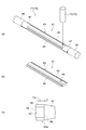
- the molded product 41 will be described with reference to FIG. 4 (a).
- the molded product 41 includes a molded main body 45 having a pipe portion 43 and a flange portion 44, held portions 46 on both ends in the longitudinal direction, and a gradual change portion 47 between the molded main body 45 and the held portion 46.
- the molding main body portion 45 is a portion that becomes a final product by being laser-processed.
- the pipe portion 43 is a hollow portion.
- the flange portion 44 is a plate-shaped portion that protrudes from the pipe portion 43 by crushing a part of the metal pipe material 40.
- the held portion 46 is a cylindrical portion held by the electrodes 26 and 27.
- the nozzle 31 is inserted into the held portion 46.
- the gradual change portion 47 is a transition portion that changes from the shape of the held portion 46 to the shape of the molding main body portion 45.
- the molded product 41 molded by the molding device 1 is supplied to the cooling unit 90.
- the molded product 41 may be sequentially supplied to the cooling unit 90 from the one molded by the molding apparatus 1. Alternatively, after a certain number of molded products 41 have been accumulated at the accumulation location, they may be collectively supplied to the cooling unit 90.
- the temperature of the molded products 41 can be lowered before laser processing due to the cooling effect of natural heat dissipation.
- the cooling unit 90 is a device that positively cools the molded product 41 removed from the molding mold 2.
- the cooling unit 90 positively cools the molded product 41 before trimming by the laser processing device 70.
- the positive cooling is to cool the molded product 41 with a higher cooling capacity than when it is left at room temperature by performing an active treatment on the molded product 41.
- a mechanism for supplying a cooling medium such as cold air, cold water, ice, and dry ice to the molded product 41 may be adopted.
- the cooling unit 90 may blow cold air onto the molded product 41 on the conveyor.
- the transport equipment corresponds to a cooling unit 90 that actively cools.
- the cooling unit 90 may blast dry ice.
- a device such as a refrigerator for accommodating the molded product 41 in a low temperature atmosphere may be adopted.
- the cooling unit 90 even if the configuration is such that the fan is rotated near the molded product 41, since the positive treatment is performed so as to promote the cooling, it corresponds to the positive cooling by the cooling unit 90.
- the temperature to which the cooling unit 90 cools the molded product 41 will be described later.
- the molded product 41 cooled by the cooling unit 90 is supplied to the laser processing apparatus 70.
- the molded product 41 may be sequentially supplied to the laser processing apparatus 70 from the one cooled by the cooling unit 90. Alternatively, after a certain number of molded products 41 have been accumulated at the accumulation location, they may be collectively supplied to the laser processing apparatus 70.
- the temperature of the molded products 41 can be further lowered before laser processing due to the cooling effect of natural heat dissipation.
- the laser processing device 70 is a device that processes the molded product 41 cooled by the cooling unit 90 with a laser.
- the laser processing apparatus 70 irradiates the molded product 41 with a laser to perform processing such as cutting, drilling, and forming a notch.
- FIG. 4 is a perspective view showing a state of laser processing by the laser processing device 70.
- the laser processing apparatus 70 includes an installation portion 71 and a laser head 72.
- the installation portion 71 is a portion for installing the molded product 41 at a position facing the laser head 72.
- the installation portion 71 has a support portion (not shown), and the support portion supports the molded product 41.
- the molded product 41 is installed in the installation portion 51 at a position and posture suitable for laser processing.
- the laser head 72 is a portion for processing the molded product 41 by irradiating the molded product 41 with a laser.
- the laser head 72 removes the gradual change portion 47 and the held portion 46 from the molding main body 45 by cutting the vicinity of both ends of the molding main body 45, as shown in FIG. 4 (b). Further, the laser head 72 forms a hole 49 at a predetermined position of the molding main body 45.
- the laser processing apparatus 70 cuts and trims the end portion of the molding body portion 45 of the molded product 41. Trimming will be described with reference to FIG. 4 (c). Trimming is a cutting process for cutting the end portion 45a of the molding main body portion 45.
- the "end portion of the molding main body portion” is a region near the boundary portion BL between the gradually changing portion 47 and the molding main body portion 45.
- the cutting line CL by the laser is set at a position separated from the boundary portion BL inward in the longitudinal direction by a predetermined dimension t.
- the predetermined dimension t is appropriately set in the range of 5 mm to 20 mm.
- the laser processing device 70 performs trimming when the temperature of the molded product 41 falls below a predetermined temperature.
- the predetermined temperature may be a temperature in which the thermal expansion of the molded product 41 is in the range of 0.5% or less.
- the length dimension L2 of the molded product 41 at the time of cutting is set with reference to the length dimension L1 of the metal pipe material 40 at room temperature before heating, it is defined as "100 ⁇ (L2-L1) / L1".
- the value corresponds to the value of thermal expansion.
- thermal expansion here refers to a state of thermal expansion when viewed from a metal material at room temperature before heating. That is, the metal material thermally expands by heating and then cools and contracts by cooling the cooling unit 90.
- This predetermined temperature is at least lower than the temperature of 200 to 250 ° C., which is the temperature at the end point of the martensitic transformation described above.
- the predetermined temperature may be, for example, 150 ° C. However, it does not have to be limited to the temperature.
- the predetermined temperature may be set in the range of, for example, room temperature (about 20 ° C.) to 150 ° C. As a result, it is possible to prevent the molded product 41 from being cooled during cutting and causing a cutting error due to the effect of shrinkage due to the cooling.
- the cooling unit 90 adjusts the cooling capacity so that the temperature of the molded product 41 at the time of cutting satisfies the above conditions.
- the laser processing apparatus 70 may perform trimming after the molded product 41 has reached room temperature.
- the molded product 41 processed by the laser processing device 70 is supplied to the blasting device 50.
- the molded product 41 may be supplied to the blasting device 50 in order from the one processed by the laser processing device 70. Alternatively, after a certain number of molded products 41 have been accumulated at the accumulation location, they may be collectively supplied to the blasting apparatus 50.
- the blasting device 50 is a device that removes scale from the molded product 41 processed by the laser processing device 70.
- the scale is an oxide film formed on the surface of the metal pipe material 40 by heating the metal pipe material 40 in the molding apparatus 1.
- the blasting device 50 injects particles onto the surface of the molded product 41.
- the blasting device 50 removes the scale from the surface of the molded product 41 by the impact caused by the collision of the particles.
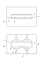
- FIG. 5A is a schematic view showing the blasting device 50 of the present embodiment.
- the blasting device 50 according to the present embodiment removes the scale on the outer peripheral surface of the molded product 41.
- the blasting device 50 does not inject particles onto the inner peripheral surface so as not to leave particles inside the molded product 41.
- the molded product 41 has a flange portion 44 by crushing a part of the metal pipe material 40. In the internal space of the molded product 41, particles tend to remain in such a flange portion 44. Therefore, the blasting device 50 injects particles only on the outer peripheral surface of the molded product 41.
- the blasting device 50 has an installation portion 51, a nozzle 52, and a shielding wall 53.
- the installation portion 51 is a portion for installing the molded product 41 at a position facing the nozzle 52.
- the installation portion 51 has a support portion (not shown), and the support portion supports the molded product 41.
- the molded product 41 is installed in the installation portion 51 at a position and posture suitable for blasting.
- the installation portion 51 is installed in a posture in which the molded product 41 is suspended and extends in the vertical direction.
- the nozzle 52 is a member that irradiates the molded product 41 with the particles 55.
- the particles for example, materials such as sand, plastic, dry ice, and iron pieces are adopted.
- the nozzle 52 is arranged around the molded product 41 installed in the installation portion 51.
- the nozzle 52 is arranged so that the injection port faces the outer peripheral surface of the molded product 41. As a result, the nozzle 52 can inject the particles 55 onto the outer peripheral surface of the molded product 41.
- the shielding wall 53 is a wall body that shields the particles 55.
- the shielding wall 53 is arranged so as to surround the installation portion 51 and the nozzle 52. As a result, the shielding wall 53 can prevent the particles 55 from scattering around the blasting device 50. That is, the shielding wall 53 can prevent the particles 55 from scattering to the molding apparatus 1 and the laser processing apparatus 70.
- a wall portion that partitions the space between the blasting device 50 and the laser processing device 70 may be provided.
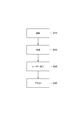
- FIG. 6 is a process diagram showing a molding method according to the present embodiment.
- the molding method includes a molding step S10, a cooling step S20, a laser processing step S30 (cutting step), and a blast step S40.
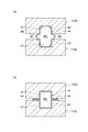
- a fluid is supplied to the heated metal pipe material 40, and the expanded metal pipe material 40 is brought into contact with the molding surface of the molding die 2 to mold the molded product 41.
- the molded product 41 is molded using the molding apparatus 1 shown in FIG.
- the cooling step S20 is a step of positively cooling the molded product 41 taken out from the molding die 2.
- the laser processing step S30 is a step of processing the molded product 41 removed from the molding die 2.
- the laser processing apparatus 70 shown in FIG. 4 processes the molded product 41.
- the blasting step S40 is a step of removing scale from the molded product 41 processed in the laser processing step S30.
- the blasting apparatus 50 shown in FIG. 5A performs a blasting process to remove the scale from the molded product 41.
- the molding apparatus 1 for molding the heated metal pipe material 40 with the molding die 2 and the end portion 45a of the molding main body portion 45 of the molded product 41 are cut.
- a laser processing device 70 for trimming is provided, and the laser processing device 70 performs trimming when the temperature of the molded product 41 becomes equal to or lower than a predetermined temperature.
- the laser processing device 70 cuts and trims the end portion 45a of the molding body portion 45 of the molded product 41 molded by the molding device 1. As a result, the molded product 41 is cut to a desired length.
- the laser processing apparatus 70 performs trimming when the temperature of the molded product 41 becomes equal to or lower than a predetermined temperature. Therefore, the laser processing apparatus 70 can perform trimming in a state where the temperature of the molded product 41 is lowered to reduce the influence of cooling shrinkage. From the above, the cutting accuracy of the molded product 41 can be improved.
- the predetermined temperature may be 150 ° C. In this case, the influence of the cooling shrinkage of the molded product 41 can be sufficiently reduced.
- the molding system 100 may further include a cooling unit 90 that positively cools the molded product 41 before trimming by the laser processing device 70.
- the cooling unit 90 can quickly cool the molded product 41 to a predetermined temperature or lower.
- the molding system 100 is a molding die for molding a molded product 41 by bringing a fluid supply unit 6 for supplying a fluid to a heated metal pipe material 40 and an expanded metal pipe material 40 into contact with a molding surface.
- a molding apparatus 1 including a mold 2 and a laser processing apparatus 70 for cutting and trimming an end portion 45a of a molding body portion 45 of a molded product 41 are provided. Further, the molding system 100 according to the present embodiment cuts and trims the molding apparatus 1 that molds the heated metal pipe material 40 with the molding die 2 and the end portion 45a of the molding body portion 45 of the molded product 41.
- a laser processing device 70 is provided.
- the laser processing device 70 can obtain a molded product 41 having a desired length by cutting the end portion 45a of the molding main body portion 45 of the molded product 41 and performing trimming.
- the molding method according to the present embodiment includes a molding step S10 for molding the heated metal pipe material 40 with the molding die 2 and a cutting step S20 for cutting and trimming the end portion 45a of the molding body portion 45 of the molded product 41.
- trimming is performed when the temperature of the molded product 41 becomes equal to or lower than a predetermined temperature.
- the molding system 200 includes a first blasting device 50 arranged in front of the laser processing device 70 and a second blasting device 80 that removes scale from the molded product 41 processed by the laser processing device 70.
- the first blasting device 50 at this time corresponding to the "cooling unit" in the claim may inject dry ice as the particles 55. Even if the first blasting device 50 injects particles 55 other than dry ice, a cooling effect can be obtained due to the influence of blowing air, but a high cooling effect can be obtained by injecting dry ice.
- the second blasting device 80 injects particles 55 from the blast hose 56 onto the inner peripheral surface of the molded product 41.
- the blast hose 56 is inserted into the molded product 41 and ejects particles toward the inner peripheral surface inside the molded product 41.
- the blast hose 56 may inject dry ice as the particles 55.
- the dry ice collides with the inner peripheral surface of the molded product 41 as a solid and removes the scale, but it becomes a gas and disappears with the passage of time. Therefore, it is possible to prevent the particles 55 from remaining on the flange portion 44.
- the first blasting device 50 and the second blasting device 80 may be configured by a common device.
- the blast hose 56 of FIG. 5 (b) may be added to the blast device 50 of FIG. 5 (a).
- the blast hose 56 blasts the inner peripheral surface of the molded product 41. From the above, the number of devices of the molding system 200 can be reduced.
- the present invention is not limited to the above-described embodiment.
- the blasting device was exemplified as the scale removing unit.
- any device may be adopted as the scale removing unit as long as it can remove the scale.
- one that injects a fluid onto a molded product or removes scale by ultrasonic cleaning may be adopted.
- Such a scale removing portion also has a cooling effect.
- the cutting portion is not limited to the laser processing device, and a device by another cutting method may be adopted.
- the molding method is not particularly limited as long as it is a molding method using a heated metal material.
- a molding method using hot stamping may be adopted. Therefore, the metal material does not necessarily have to be a metal pipe material, and may be a plate material or a pillar material.
- the molding apparatus 1 is not limited to the configuration shown in FIG. 2, for example, the molding apparatus 1 may adopt the configuration shown in FIG. In the molding apparatus 1 shown in FIG. 8, the thermal expansion unit 150 as shown in FIG. 9 may be adopted.
- FIG. 9A is a schematic side view showing a heating expansion unit 150 in which the components of the holding unit 4, the heating unit 5, and the fluid supply unit 6 are unitized.
- FIG. 9B is a cross-sectional view showing a state when the nozzle 31 seals the metal pipe material 40.
- the thermal expansion unit 150 includes the lower electrode 26 and the upper electrode 27 described above, an electrode mounting unit 151 on which the electrodes 26 and 27 are mounted, the nozzle 31 described above, and the drive mechanism 32. , Elevating unit 152 and unit base 153.
- the electrode mounting unit 151 includes an elevating frame 154 and electrode frames 156 and 157.
- the electrode frames 156 and 157 function as a part of a drive mechanism 60 that supports and moves the electrodes 26 and 27.
- the drive mechanism 32 drives the nozzle 31 and moves up and down together with the electrode mounting unit 151.
- the drive mechanism 32 includes a piston 61 that holds the nozzle 31 and a cylinder 62 that drives the piston.
- the elevating unit 152 includes an elevating frame base 64 attached to the upper surface of the unit base 153, and an elevating actuator 66 that imparts an elevating operation to the elevating frame 154 of the electrode mounting unit 151 by these elevating frame bases 64. ing.
- the elevating frame base 64 has guide portions 64a and 64b that guide the elevating operation of the elevating frame 154 with respect to the unit base 153.
- the elevating unit 152 functions as a part of the drive mechanism 60 of the holding unit 4.
- the thermal expansion unit 150 has a plurality of unit bases 153 having different inclination angles on the upper surface, and by exchanging these, the lower electrode 26 and the upper electrode 27, the nozzle 31, the electrode mounting unit 151, the drive mechanism 32, and the elevating mechanism 32 are moved up and down. It is possible to change and adjust the tilt angle of the unit 152 at once.
- the nozzle 31 is a cylindrical member into which the end of the metal pipe material 40 can be inserted.
- the nozzle 31 is supported by the drive mechanism 32 so that the center line of the nozzle 31 coincides with the reference line SL1.
- the inner diameter of the supply port 31a at the end of the nozzle 31 on the metal pipe material 40 side substantially matches the outer diameter of the metal pipe material 40 after expansion molding.
- the nozzle 31 supplies a high-pressure fluid to the metal pipe material 40 from the internal flow path 63.
- An example of a high-pressure fluid is gas or the like.
- molding device 1 ... molding device, 2 ... molding die, 40 ... metal pipe material, 41 ... molded product, 70 ... laser processing device (cutting part), 90 ... cooling part, 100 ... molding system.
Landscapes
- Engineering & Computer Science (AREA)
- Mechanical Engineering (AREA)
- Physics & Mathematics (AREA)
- Optics & Photonics (AREA)
- Fluid Mechanics (AREA)
- Plasma & Fusion (AREA)
- Shaping Metal By Deep-Drawing, Or The Like (AREA)
- Mounting, Exchange, And Manufacturing Of Dies (AREA)
- Moulds For Moulding Plastics Or The Like (AREA)
Abstract
Description
図1は、第1実施形態に係る成形システム100の構成を示す概略構成図である。図1に示すように、成形システム100は、成形装置1と、冷却部90と、レーザー加工装置70(切断部)と、ブラスト装置50と、を備える。
次に、図7を参照して、第2実施形態に係る成形システム200について説明する。図7に示すように、成形システム200は、レーザー加工装置70の前段に配置される第1ブラスト装置50と、レーザー加工装置70で加工された成形品41からスケールを除去する第2ブラスト装置80を備える。なお、ここでは、第1ブラスト装置50が請求項における「冷却部」に対応するこのときの第1ブラスト装置50は、粒子55としてドライアイスを噴射してよい。第1ブラスト装置50は、ドライアイス以外の粒子55を噴射しても、送風の影響によって冷却効果を得ることができるが、ドライアイスを噴射することで高い冷却効果を得ることができる。
Claims (6)
- 加熱された金属材料を成形金型で成形する成形装置と、
成形品の成形本体部の端部を切断してトリミングする切断部と、を備え、
前記切断部は、前記成形品が所定の温度以下になったら前記トリミングを行う、成形システム。 - 前記所定の温度は、前記成形品の熱膨張が0.5%以下の範囲となる温度である、請求項1に記載の成形システム。
- 前記切断部による前記トリミングの前段階で、前記成形品を積極的に冷却する冷却部を更に備える、請求項1又は2に記載の成形システム。
- 加熱された金属パイプ材料に流体を供給する流体供給部、及び膨張した前記金属パイプ材料を成形面に接触させることで成形品を成形する成形金型を備える成形装置と、
前記成形品の成形本体部の端部を切断してトリミングする切断部と、を備える、成形システム。 - 加熱された金属材料を成形金型で成形する成形装置と、
成形品の成形本体部の端部を切断してトリミングする切断部と、を備える、成形システム。 - 加熱された金属材料を成形金型で成形する成形工程と、
成形品の成形本体部の端部を切断してトリミングする切断工程と、を備え、
前記切断工程では、前記成形品が所定の温度以下になったら前記トリミングを行う、成形方法。
Priority Applications (4)
| Application Number | Priority Date | Filing Date | Title |
|---|---|---|---|
| CA3160318A CA3160318C (en) | 2020-03-10 | 2021-03-05 | SYSTEM AND METHOD OF SHAPING |
| KR1020227015142A KR102915216B1 (ko) | 2020-03-10 | 2021-03-05 | 성형시스템, 및 성형방법 |
| CN202180006490.4A CN114728385A (zh) | 2020-03-10 | 2021-03-05 | 成型系统及成型方法 |
| JP2022507156A JP7626752B2 (ja) | 2020-03-10 | 2021-03-05 | 成形システム、及び成形方法 |
Applications Claiming Priority (2)
| Application Number | Priority Date | Filing Date | Title |
|---|---|---|---|
| JP2020-040978 | 2020-03-10 | ||
| JP2020040978 | 2020-03-10 |
Publications (1)
| Publication Number | Publication Date |
|---|---|
| WO2021182359A1 true WO2021182359A1 (ja) | 2021-09-16 |
Family
ID=77671663
Family Applications (1)
| Application Number | Title | Priority Date | Filing Date |
|---|---|---|---|
| PCT/JP2021/008834 Ceased WO2021182359A1 (ja) | 2020-03-10 | 2021-03-05 | 成形システム、及び成形方法 |
Country Status (5)
| Country | Link |
|---|---|
| JP (1) | JP7626752B2 (ja) |
| KR (1) | KR102915216B1 (ja) |
| CN (1) | CN114728385A (ja) |
| CA (1) | CA3160318C (ja) |
| WO (1) | WO2021182359A1 (ja) |
Citations (3)
| Publication number | Priority date | Publication date | Assignee | Title |
|---|---|---|---|---|
| JPH06248402A (ja) * | 1993-02-23 | 1994-09-06 | Mazda Motor Corp | マグネシウム合金製部材の製造方法 |
| JP2009220141A (ja) * | 2008-03-14 | 2009-10-01 | Marujun Co Ltd | パイプ製品の製造方法及び同製造装置 |
| JP2018130761A (ja) * | 2017-02-17 | 2018-08-23 | エムエス オートテック カンパニー リミテッドMs Autotech Co.,Ltd. | ホットスタンピング方法 |
Family Cites Families (5)
| Publication number | Priority date | Publication date | Assignee | Title |
|---|---|---|---|---|
| JP2006305821A (ja) * | 2005-04-27 | 2006-11-09 | Bridgestone Corp | 押出機、温度測定装置および成形材料の温度制御方法 |
| JP5014295B2 (ja) * | 2008-09-25 | 2012-08-29 | 株式会社アマダ | 熱切断加工用の冷却媒体供給ヘッドおよびパイプ冷却装置 |
| JP5014311B2 (ja) * | 2008-11-05 | 2012-08-29 | 株式会社アマダ | 熱切断加工装置 |
| EP3936322B1 (en) * | 2014-06-19 | 2025-07-30 | Sumitomo Heavy Industries, Ltd. | Forming system |
| KR102009006B1 (ko) * | 2019-03-20 | 2019-10-21 | 주식회사 퍼팩트 | 수밀성 및 안정성을 향상시킨 상하수도관 제조방법 및 그 제조방법으로 제조된 상하수도관 |
-
2021
- 2021-03-05 WO PCT/JP2021/008834 patent/WO2021182359A1/ja not_active Ceased
- 2021-03-05 JP JP2022507156A patent/JP7626752B2/ja active Active
- 2021-03-05 CA CA3160318A patent/CA3160318C/en active Active
- 2021-03-05 KR KR1020227015142A patent/KR102915216B1/ko active Active
- 2021-03-05 CN CN202180006490.4A patent/CN114728385A/zh active Pending
Patent Citations (3)
| Publication number | Priority date | Publication date | Assignee | Title |
|---|---|---|---|---|
| JPH06248402A (ja) * | 1993-02-23 | 1994-09-06 | Mazda Motor Corp | マグネシウム合金製部材の製造方法 |
| JP2009220141A (ja) * | 2008-03-14 | 2009-10-01 | Marujun Co Ltd | パイプ製品の製造方法及び同製造装置 |
| JP2018130761A (ja) * | 2017-02-17 | 2018-08-23 | エムエス オートテック カンパニー リミテッドMs Autotech Co.,Ltd. | ホットスタンピング方法 |
Also Published As
| Publication number | Publication date |
|---|---|
| KR20220149652A (ko) | 2022-11-08 |
| CA3160318C (en) | 2025-06-10 |
| CN114728385A (zh) | 2022-07-08 |
| JP7626752B2 (ja) | 2025-02-04 |
| KR102915216B1 (ko) | 2026-01-19 |
| CA3160318A1 (en) | 2021-09-16 |
| JPWO2021182359A1 (ja) | 2021-09-16 |
Similar Documents
| Publication | Publication Date | Title |
|---|---|---|
| CN106457346A (zh) | 成型装置及成型方法 | |
| JP7626752B2 (ja) | 成形システム、及び成形方法 | |
| WO2015194600A1 (ja) | 成形システム | |
| WO2021182358A1 (ja) | 成形システム、及び成形方法 | |
| WO2021182349A1 (ja) | 成形システム、及び成形方法 | |
| US20240253103A1 (en) | Forming device and forming method | |
| US20240149323A1 (en) | Molding device | |
| EP4400228A1 (en) | Molding device | |
| JP6364536B2 (ja) | レーザ切断加工方法及び装置 | |
| WO2023157698A1 (ja) | 成形装置 | |
| JP7303718B2 (ja) | 成形装置及びブロー成形用の金属パイプ材料 | |
| JP6728827B2 (ja) | 冷却処理設備及び冷却処理方法 | |
| US20260084200A1 (en) | Forming device | |
| JP2022043699A (ja) | 成形型 | |
| US20250222510A1 (en) | Forming system | |
| JP2021154338A (ja) | レーザー加工装置 | |
| WO2021176850A1 (ja) | 成形装置、及び成形方法 | |
| CN121464006A (zh) | 成型装置、成型系统及金属管 | |
| KR101431624B1 (ko) | 냉각장치 및 이를 포함하는 열처리 장치 | |
| CN119730973A (zh) | 成型装置及金属部件 | |
| JP7351772B2 (ja) | 成形装置 | |
| JP2021154346A (ja) | 加工装置 |
Legal Events
| Date | Code | Title | Description |
|---|---|---|---|
| 121 | Ep: the epo has been informed by wipo that ep was designated in this application |
Ref document number: 21767900 Country of ref document: EP Kind code of ref document: A1 |
|
| ENP | Entry into the national phase |
Ref document number: 2022507156 Country of ref document: JP Kind code of ref document: A |
|
| ENP | Entry into the national phase |
Ref document number: 3160318 Country of ref document: CA |
|
| NENP | Non-entry into the national phase |
Ref country code: DE |
|
| 122 | Ep: pct application non-entry in european phase |
Ref document number: 21767900 Country of ref document: EP Kind code of ref document: A1 |