WO2021182066A1 - 医療用画像処理装置および医療用観察システム - Google Patents
医療用画像処理装置および医療用観察システム Download PDFInfo
- Publication number
- WO2021182066A1 WO2021182066A1 PCT/JP2021/006220 JP2021006220W WO2021182066A1 WO 2021182066 A1 WO2021182066 A1 WO 2021182066A1 JP 2021006220 W JP2021006220 W JP 2021006220W WO 2021182066 A1 WO2021182066 A1 WO 2021182066A1
- Authority
- WO
- WIPO (PCT)
- Prior art keywords
- image
- unit
- subject
- subject image
- divided
- Prior art date
- Legal status (The legal status is an assumption and is not a legal conclusion. Google has not performed a legal analysis and makes no representation as to the accuracy of the status listed.)
- Ceased
Links
Images

Classifications
-
- G—PHYSICS
- G02—OPTICS
- G02B—OPTICAL ELEMENTS, SYSTEMS OR APPARATUS
- G02B21/00—Microscopes
- G02B21/0004—Microscopes specially adapted for specific applications
- G02B21/0012—Surgical microscopes
-
- G—PHYSICS
- G06—COMPUTING OR CALCULATING; COUNTING
- G06T—IMAGE DATA PROCESSING OR GENERATION, IN GENERAL
- G06T11/00—Two-dimensional [2D] image generation
-
- A—HUMAN NECESSITIES
- A61—MEDICAL OR VETERINARY SCIENCE; HYGIENE
- A61B—DIAGNOSIS; SURGERY; IDENTIFICATION
- A61B90/00—Instruments, implements or accessories specially adapted for surgery or diagnosis and not covered by any of the groups A61B1/00 - A61B50/00, e.g. for luxation treatment or for protecting wound edges
- A61B90/20—Surgical microscopes characterised by non-optical aspects
- A61B90/25—Supports therefor
-
- G—PHYSICS
- G06—COMPUTING OR CALCULATING; COUNTING
- G06T—IMAGE DATA PROCESSING OR GENERATION, IN GENERAL
- G06T5/00—Image enhancement or restoration
- G06T5/73—Deblurring; Sharpening
-
- A—HUMAN NECESSITIES
- A61—MEDICAL OR VETERINARY SCIENCE; HYGIENE
- A61B—DIAGNOSIS; SURGERY; IDENTIFICATION
- A61B1/00—Instruments for performing medical examinations of the interior of cavities or tubes of the body by visual or photographical inspection, e.g. endoscopes; Illuminating arrangements therefor
- A61B1/00163—Optical arrangements
- A61B1/00188—Optical arrangements with focusing or zooming features
-
- A—HUMAN NECESSITIES
- A61—MEDICAL OR VETERINARY SCIENCE; HYGIENE
- A61B—DIAGNOSIS; SURGERY; IDENTIFICATION
- A61B34/00—Computer-aided surgery; Manipulators or robots specially adapted for use in surgery
- A61B34/20—Surgical navigation systems; Devices for tracking or guiding surgical instruments, e.g. for frameless stereotaxis
- A61B2034/2046—Tracking techniques
- A61B2034/2059—Mechanical position encoders
-
- A—HUMAN NECESSITIES
- A61—MEDICAL OR VETERINARY SCIENCE; HYGIENE
- A61B—DIAGNOSIS; SURGERY; IDENTIFICATION
- A61B90/00—Instruments, implements or accessories specially adapted for surgery or diagnosis and not covered by any of the groups A61B1/00 - A61B50/00, e.g. for luxation treatment or for protecting wound edges
- A61B90/30—Devices for illuminating a surgical field, the devices having an interrelation with other surgical devices or with a surgical procedure
- A61B2090/306—Devices for illuminating a surgical field, the devices having an interrelation with other surgical devices or with a surgical procedure using optical fibres
-
- A—HUMAN NECESSITIES
- A61—MEDICAL OR VETERINARY SCIENCE; HYGIENE
- A61B—DIAGNOSIS; SURGERY; IDENTIFICATION
- A61B90/00—Instruments, implements or accessories specially adapted for surgery or diagnosis and not covered by any of the groups A61B1/00 - A61B50/00, e.g. for luxation treatment or for protecting wound edges
- A61B90/20—Surgical microscopes characterised by non-optical aspects
-
- G—PHYSICS
- G06—COMPUTING OR CALCULATING; COUNTING
- G06T—IMAGE DATA PROCESSING OR GENERATION, IN GENERAL
- G06T2207/00—Indexing scheme for image analysis or image enhancement
- G06T2207/10—Image acquisition modality
- G06T2207/10028—Range image; Depth image; 3D point clouds
-
- G—PHYSICS
- G06—COMPUTING OR CALCULATING; COUNTING
- G06T—IMAGE DATA PROCESSING OR GENERATION, IN GENERAL
- G06T2207/00—Indexing scheme for image analysis or image enhancement
- G06T2207/20—Special algorithmic details
- G06T2207/20021—Dividing image into blocks, subimages or windows
-
- G—PHYSICS
- G06—COMPUTING OR CALCULATING; COUNTING
- G06T—IMAGE DATA PROCESSING OR GENERATION, IN GENERAL
- G06T2207/00—Indexing scheme for image analysis or image enhancement
- G06T2207/20—Special algorithmic details
- G06T2207/20172—Image enhancement details
- G06T2207/20201—Motion blur correction
-
- G—PHYSICS
- G06—COMPUTING OR CALCULATING; COUNTING
- G06T—IMAGE DATA PROCESSING OR GENERATION, IN GENERAL
- G06T2207/00—Indexing scheme for image analysis or image enhancement
- G06T2207/30—Subject of image; Context of image processing
- G06T2207/30004—Biomedical image processing
Definitions
- the present disclosure relates to a medical image processing device and a medical observation system that perform image processing on image data input from the outside.
- a support part having a plurality of arm parts and a tip of the support part are used as a medical observation system for observing a minute part in the brain, heart, or the like of a patient to be observed.
- an optical microscope system provided in the above, which includes a magnifying optical system for enlarging the minute portion and a microscope unit (imaging unit) having an imaging element.
- an operator such as a doctor moves the microscope unit and arranges it at a desired position, and performs the operation while observing an image captured by the microscope unit.
- an endoscopic system having an endoscopic section (imaging section) for imaging the surgical site is known as a medical observation system for observing a surgical site when performing an intraperitoneal operation on a patient.
- the blurring may increase depending on the blurring method (direction of blurring and amount of blurring) of the subject.
- the present disclosure has been made in view of the above, and an object of the present disclosure is to provide a medical image processing device and a medical observation system capable of appropriately performing blur correction of an image in which a plurality of subjects are captured.
- the medical image processing apparatus includes a divided portion for dividing at least one subject image existing in an image and the subject image divided by the divided portion.
- a detection unit that detects blur, a subject image divided by the division unit, a correction unit that corrects the blur of the subject image based on the blur detected by the detection unit, a corrected subject image, and the subject. It includes a compositing unit that synthesizes a background image formed by a region other than the image.
- the medical image processing apparatus is based on the depth map information in which the divided portion is associated with the distance between the imaging unit that captures an image and the subject and the position of the image. To divide the subject image.
- the compositing unit enlarges the subject image at a preset enlargement ratio, and synthesizes the enlarged subject image and the background image. do.
- the division unit divides the plurality of subject images
- the detection unit is the detection unit.
- blurring was detected for each subject image
- the correction unit detected each subject image divided by the divided unit and the detecting unit detected each subject image.
- the blur of each subject image is corrected based on the blur, and the compositing unit synthesizes each corrected subject image and a background image formed by regions other than the plurality of subject images.
- the medical observation system includes an imaging unit that photographs the surgical site of a patient on an operating table and outputs a video signal, and at least one subject existing in an image generated based on the video signal.
- the subject image is based on a division unit that divides the image, a detection unit that detects blurring of the subject image divided by the division unit, a subject image divided by the division unit, and blur detection detected by the detection unit. It includes a correction unit for correcting blurring, and a composition unit for synthesizing the corrected subject image and a background image formed by a region other than the subject image.
- FIG. 1 is a diagram showing a configuration of a medical observation system according to an embodiment of the present disclosure.
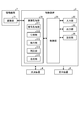
- FIG. 2 is a block diagram showing a configuration of a control device for a medical observation system according to an embodiment of the present disclosure.
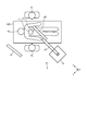
- FIG. 3 is a diagram for explaining a usage mode of the microscope device of the medical observation system according to the embodiment of the present disclosure.
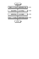
- FIG. 4 is a flowchart illustrating image processing performed by the control device of the medical observation system according to the embodiment of the present disclosure.
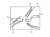
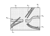
- FIG. 5 is a diagram (No. 1) for explaining the division process performed by the division unit.
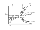
- FIG. 6 is a diagram (No. 2) for explaining the division process performed by the division unit.
- FIG. 7 is a diagram illustrating a synthesis process performed by the synthesis unit.
- FIG. 8 is a diagram showing a configuration of a medical observation system according to a modified example of the present disclosure.
- FIG. 1 is a diagram showing a configuration of a medical observation system according to an embodiment.
- FIG. 2 is a block diagram showing a configuration of a control device of the medical observation system according to the embodiment.
- the medical observation system 1 includes a microscope device 2 having a function as a microscope for magnifying and imaging the fine structure of an object to be observed, a control device 3 for controlling the operation of the medical observation system 1, and a microscope device. It includes a display device 4 that displays an image captured by 2 and a light source device 8 that supplies illumination light to the microscope device 2.
- the microscope device 2 is provided at the base portion 5 that can move on the floor surface, the support portion 6 that is supported by the base portion 5, and the tip of the support portion 6, and magnifies and images a minute part of the object to be observed.
- a columnar microscope unit 7 is provided.
- a transmission cable including a signal line for transmitting a signal between the control device 3 and the microscope unit 7, and a guide for guiding the illumination light from the light source device 8 to the microscope unit 7.
- a group of cables including a light guide cable and the like is arranged from the base portion 5 to the microscope portion 7.
- the support portion 6 includes a first joint portion 11, a first arm portion 21, a second joint portion 12, a second arm portion 22, a third joint portion 13, a third arm portion 23, a fourth joint portion 14, and a fourth arm. It has a portion 24, a fifth joint portion 15, a fifth arm portion 25, and a sixth joint portion 16.
- the support portion 6 has four sets of joint portions that rotatably connect the two arm portions and one (tip side) of the two arm portions to the other (base end side). Specifically, these four sets include (first arm portion 21, second joint portion 12, second arm portion 22), (second arm portion 22, third joint portion 13, third arm portion 23), and the like. (3rd arm portion 23, 4th joint portion 14, 4th arm portion 24), (4th arm portion 24, 5th joint portion 15, 5th arm portion 25).
- the first joint portion 11 rotatably holds the microscope portion 7 on the distal end side, and is held by the first arm portion 21 in a state of being fixed to the distal end portion of the first arm portion 21 on the proximal end side.
- the first joint portion 11 has a cylindrical shape and holds the microscope portion 7 so as to be rotatable around the first axis O 1 which is the central axis in the height direction.
- the first arm portion 21 has a shape extending from the side surface of the first joint portion 11 in a direction orthogonal to the first axis O 1.
- the second joint portion 12 rotatably holds the first arm portion 21 on the tip end side, and is held by the second arm portion 22 in a state of being fixed to the tip end portion of the second arm portion 22 on the proximal end side.
- the second joint portion 12 has a cylindrical shape, and the first arm portion 21 is rotatable around the second axis O 2 , which is the central axis in the height direction and is the axis orthogonal to the first axis O 1.
- the second arm portion 22 has a substantially L-shape, and is connected to the second joint portion 12 at the end of the L-shaped vertical line portion.
- the third joint portion 13 rotatably holds the L-shaped horizontal line portion of the second arm portion 22 on the tip end side, and is fixed to the tip end portion of the third arm portion 23 on the proximal end side. It is held by the arm portion 23.
- the third joint portion 13 has a cylindrical shape, is a central axis in the height direction , is an axis orthogonal to the second axis O 2 , and is an axis parallel to the direction in which the second arm portion 22 extends.
- the second arm portion 22 is rotatably held around the third axis O 3.
- the tip end side of the third arm portion 23 has a cylindrical shape, and a hole portion penetrating in a direction orthogonal to the height direction of the tip end side cylinder is formed on the base end side.
- the third joint portion 13 is rotatably held by the fourth joint portion 14 via the hole portion.
- the fourth joint portion 14 rotatably holds the third arm portion 23 on the distal end side, and is held by the fourth arm portion 24 in a state of being fixed to the fourth arm portion 24 on the proximal end side.
- the fourth joint portion 14 has a cylindrical shape, and the third arm portion 23 is rotatable around the fourth axis O 4 , which is the central axis in the height direction and is the axis orthogonal to the third axis O 3. To hold.
- the fifth joint portion 15 rotatably holds the fourth arm portion 24 on the distal end side, and is fixedly attached to the fifth arm portion 25 on the proximal end side.
- the fifth joint portion 15 has a cylindrical shape, and the fourth arm portion 24 can be rotated around the fifth axis O 5 which is the central axis in the height direction and is parallel to the fourth axis O 4. Hold on.
- the fifth arm portion 25 includes an L-shaped portion and a rod-shaped portion extending downward from the L-shaped horizontal line portion.
- the fifth joint portion 15 is attached to the end portion of the L-shaped vertical line portion of the fifth arm portion 25 on the proximal end side.
- the sixth joint portion 16 rotatably holds the fifth arm portion 25 on the tip end side, and is fixedly attached to the upper surface of the base portion 5 on the base end side.
- the sixth joint portion 16 has a cylindrical shape, and the fifth arm portion 25 can be rotated around the sixth axis O 6 which is the central axis in the height direction and is the axis orthogonal to the fifth axis O 5. Hold on.
- a base end portion of a rod-shaped portion of the fifth arm portion 25 is attached to the tip end side of the sixth joint portion 16.
- the support portion 6 having the configuration described above realizes a total of 6 degrees of freedom of movement in the microscope unit 7 with 3 translational degrees of freedom and 3 rotation degrees of freedom.
- the first joint portion 11 to the sixth joint portion 16 have an electromagnetic brake that prohibits the rotation of the microscope portion 7 and the first arm portion 21 to the fifth arm portion 25, respectively.
- Each electromagnetic brake is released in a state where the arm operation switch (described later) provided in the microscope unit 7 is pressed, and allows the microscope unit 7 and the first arm unit 21 to the fifth arm unit 25 to rotate.
- An air brake may be applied instead of the electromagnetic brake.
- an encoder and an actuator may be mounted on each joint.
- the encoder detects the rotation angle in the first axis O 1.
- the actuator is composed of, for example, an electric motor such as a servomotor, and is driven by control from the control device 3, causing rotation in the joint portion by a predetermined angle.
- the rotation angle in the joint portion is set by the control device 3 based on the rotation angle in each rotation axis (first axis O 1 to sixth axis O 6 ) as a value required for moving the microscope unit 7, for example. ..
- the joint portion provided with the active drive mechanism such as the actuator constitutes a rotation shaft that actively rotates by controlling the drive of the actuator.
- the microscope unit 7 has an imaging unit 71 that magnifies and captures an image of an observed object in a cylindrical housing.
- the microscope unit 7 has an arm operation switch that receives an operation input that releases the electromagnetic brake in the first joint portion 11 to the sixth joint portion 16 and allows the rotation of each joint portion, a magnifying magnification in the imaging unit, and an imaging unit.
- a cross lever that can change the focal length to the object to be observed is provided. While the user presses the arm operation switch, the electromagnetic brakes of the first joint portion 11 to the sixth joint portion 16 are released.
- the imaging unit 71 images a subject under the control of the camera head control unit 94.
- the image pickup unit 71 is configured by accommodating a plurality of lenses and an image pickup element in a housing.
- the image sensor receives the subject image formed by the lens and converts it into an electric signal (video signal).
- the image pickup unit 71 forms an observation optical system that forms an image of a subject image that has passed through the lens on the image pickup surface of the image pickup device.
- the image sensor is integrally composed of an image sensor and a TOF sensor that acquires subject distance information (hereinafter referred to as depth map information) by a TOF method.
- the image sensor is composed of a CCD (Charge Coupled Device) image sensor or a CMOS (Complementary Metal Oxide Semiconductor) image sensor.
- the depth map information is information in which the subject distance from the position of the image sensor to the corresponding position on the observation target corresponding to the pixel position in the captured image is detected for each pixel position.
- a phase difference sensor, a stereo camera, or the like may be adopted.
- the light source device 8 controls the emission of light under the control of the control device 3.
- the light source device 8 is connected to the microscope device 2 via a light source cable 81.
- An optical fiber is inserted through the light source cable 81.
- the control device 3 receives the image pickup signal output by the microscope device 2 and generates image data for display by performing predetermined signal processing on the image pickup signal.
- the control device 3 may be installed inside the base portion 5 and integrated with the microscope device 2.
- the control device 3 includes an image processing unit 31, an input unit 32, an output unit 33, a control unit 34, and a storage unit 35.
- the control device 3 generates a power supply voltage for driving the microscope device 2 and the control device 3, supplies the power supply voltage to each part of the control device 3, and supplies the power supply unit to the microscope device 2 via a transmission cable. (Not shown) and the like may be provided.
- the image processing unit 31 processes the imaging signal output by the microscope unit 7 to generate an image for display.
- the image processing unit 31 includes a signal processing unit 311, a dividing unit 312, a detecting unit 313, a correction unit 314, and a compositing unit 315.
- the signal processing unit 311 performs signal processing such as noise removal, A / D conversion, detection processing, interpolation processing, and color correction processing as necessary.
- the signal processing unit 311 generates an image signal before the blur correction processing based on the image pickup signal after the signal processing.
- the dividing unit 312 extracts an image (subject image) of the subject appearing in the image before blur correction generated by the signal processing unit 311 and divides it into a subject area including the extracted subject image.
- the image is divided into one or a plurality of subject areas and a background area excluding the subject area by the division process of the division unit 312.
- the division unit 312 extracts the subject image by using the depth map information.
- the dividing unit 312 divides the area surrounding the extracted subject as a subject area.
- the subject area may be set along the outer edge of the subject image, or may be set to an area moved outward by a predetermined distance from the outer edge of the subject image.
- the subject may be extracted and divided by contour extraction by edges or image recognition processing by machine learning.
- the detection unit 313 detects the movement of the subject in each subject area based on the image of the frame to be processed and the image acquired before the processing target.
- the detection unit 313 detects the direction in which the subject moves and the amount of movement thereof for each subject region, for example, by frequency analysis. Further, the detection unit 313 may detect the direction in which the subject moves and the amount of movement thereof by detecting the motion vector.
- a known method can be used for the detection of blurring.
- the correction unit 314 corrects the blur of the subject by applying the blur correction to the subject area.
- the correction unit 314 corrects the subject image based on the movement detected by the detection unit 313 for each subject area divided by the division unit 312.
- a known method can be used for blur correction.
- the composition unit 315 superimposes the image of the subject area corrected by the correction unit 314 on the background area and synthesizes the image. For example, the compositing unit 315 enlarges the corrected subject area at a preset enlargement ratio (> 1) and superimposes it on the corresponding position of the image.
- the composite image generated by the composite unit 315 is output to the display device 4 and displayed on the display device 4.
- the AF processing unit that outputs the predetermined AF evaluation value of each frame based on the input frame imaging signal, and the AF evaluation value of each frame from the AF processing unit. It may have an AF calculation unit that performs AF calculation processing such as selecting the most suitable frame or focus lens position as the focusing position.
- the input unit 32 is realized by using a user interface such as a keyboard, a mouse, and a touch panel, and accepts input of various information.
- a user interface such as a keyboard, a mouse, and a touch panel
- the output unit 33 is realized by using a speaker, a printer, a display, etc., and outputs various information.
- the control unit 34 performs drive control of each component including the control device 3 and the camera head 9, input / output control of information to each component, and the like.
- the control unit 34 generates a control signal by referring to the communication information data (for example, communication format information) recorded in the storage unit 35, and transmits the generated control signal to the microscope device 2.
- the communication information data for example, communication format information
- the control unit 34 generates a synchronization signal and a clock for the microscope unit 7 and the control device 3.
- a synchronization signal for example, a synchronization signal for instructing the imaging timing
- a clock for example, a clock for serial communication
- the storage unit 35 is realized by using a semiconductor memory such as a flash memory or a DRAM (Dynamic Random Access Memory), and communication information data (for example, communication format information) or the like is recorded.
- the storage unit 35 may record various programs or the like executed by the control unit 34, or may record depth map information acquired from the imaging unit 71 or a signal generated by the image sensor.
- the image processing unit 31 and the control unit 34 described above execute specific functions such as a general-purpose processor such as a CPU (Central Processing Unit) having an internal memory (not shown) in which a program is recorded and an ASIC (Application Specific Integrated Circuit). It is realized by using a dedicated processor such as various arithmetic circuits. Further, it may be configured by using FPGA (Field Programmable Gate Array: not shown) which is a kind of programmable integrated circuit. If the FPGA is configured, a memory for storing the configuration data may be provided, and the FPGA, which is a programmable integrated circuit, may be configured by the configuration data read from the memory.
- a general-purpose processor such as a CPU (Central Processing Unit) having an internal memory (not shown) in which a program is recorded and an ASIC (Application Specific Integrated Circuit). It is realized by using a dedicated processor such as various arithmetic circuits. Further, it may be configured by using FPGA (Field Programmable Gate Array: not shown) which is a
- the display device 4 receives the image data generated by the control device 3 from the control device 3 and displays the image corresponding to the image data.
- a display device 4 includes a display panel made of a CRT (Cathode Ray Tube) display, a liquid crystal display, or an organic EL (Electro Luminescence).
- an output device that outputs information using a speaker, a printer, or the like may be provided.
- the outline of the surgery performed using the medical observation system 1 having the above configuration will be described.
- the operator who is the user, operates on the head of the patient, which is the object to be observed
- the operator presses the arm operation switch of the microscope unit 7 while visually observing the image displayed by the display device 4. 7 is grasped and moved to a desired position, the imaging field of view of the microscope unit 7 is determined, and then the finger is released from the arm operation switch.
- the electromagnetic brake operates in the first joint portion 11 to the sixth joint portion 16, and the imaging field of view of the microscope portion 7 is fixed. After that, the operator adjusts the magnification and the focal length to the object to be observed.
- FIG. 3 is a diagram for explaining a usage mode of the microscope device of the medical observation system according to the embodiment of the present disclosure. It should be noted that FIG. 3 illustrates a state of the situation at the time of surgery as viewed from directly above.
- the surgeon H 1 performs the operation while observing the image of the surgical site displayed on the display device 4.
- the surgeon H 1 uses the microscope device 2 to perform an operation on the patient H 3 lying on the operating table 100.
- assistants H 2 to assist the surgery.
- an arrangement in which the display device 4 is installed so that the display device 4 can be positioned substantially in front of the operator H 1 when performing an operation in a standing position is illustrated.
- the surgeon H 1 may use the treatment tool to treat the surgical site, and the assistant H 2 may also use the treatment tool to assist.
- the microscope unit 7 captures an image including the surgical unit and the treatment tool existing in the imaging region.
- FIG. 4 is a flowchart illustrating image processing performed by the control device of the medical observation system according to the embodiment of the present disclosure.
- FIG. 4 shows a flow in which the image generated by the signal processing unit 311 is subjected to blur correction to generate an image for display.
- the dividing unit 312 extracts a subject to be captured in the image before blur correction generated by the signal processing unit 311 and divides a subject area including the extracted subject.
- the dividing unit 312 extracts a subject image using, for example, depth map information, and divides it as a subject area.
- the pre-blurring correction image W 1 shows vascular bypass surgery.
- the images W 1 before blur correction include images of blood vessels to be bypassed (blood vessel images) S B1 and S B2 , images of treatment tools held by the operator (treatment tool images) S T1 and S T2, and treatment tools held by the assistant.
- Image (treatment tool image) ST3 is shown. Blood vessels and treatment tools fluctuate in different amounts and directions, and the fluctuations appear as differences in blurring in each image.
- a blur-corrected image W divides each image and a plurality of object regions each containing a background area except each subject area. Specifically, in the image W 2 before blur correction after division, the subject areas R B1 , R B2 , R T1 , R T2 , and R T3 are set, and the subject areas R B1 , R B2 , R T1 , R T2 , and R are set. Areas other than T3 , excluding these subject areas , constitute the background image I BC (see FIG. 6). In FIG. 6, different hatching is attached to each subject area and the background image.
- step S102 the detection unit 313 detects the movement of the subject in each subject area.
- the detection unit 313 detects the direction in which the subject moves and the amount of movement thereof for each subject area.
- step S103 the correction unit 314 corrects the blur of the subject image by performing the blur correction on the subject area.
- the correction unit 314 corrects each subject area divided by the division unit 312 based on the movement detected by the detection unit 313.
- step S104 the synthesizing unit 315 superimposes the image of the subject area corrected by the correction unit 314 on the background area and synthesizes the image.
- the compositing unit 315 enlarges the corrected subject area at a preset enlargement ratio (> 1) and superimposes it on the corresponding position of the image.
- FIG. 7 is a diagram illustrating a synthesis process performed by the synthesis unit.
- the broken line indicates the outline of the subject image before enlargement.
- the composite image W 3 is a magnified image of the blood vessel image (blood vessel image S B1 , S B2 ) and the treatment tool image (treatment tool image S T1 , ST2 , S T3 ) after blur correction, and the enlarged blood vessel image (blood vessel image S T2, S T3).
- Blood vessel images Q B1 , Q B2 ) and treatment tool images (treatment tool images Q T1 , Q T2 , Q T 3 ) are superposed on the background image I BC.
- a plurality of subject images vibrating (blurring) at different frequencies are divided in the image, each is individually subjected to blur correction, and then combined to generate an image. It is possible to appropriately correct the blurring of the image in which the subject is captured.
- the signal processing unit 311 may uniformly perform blur correction processing on the image before blur correction as a whole image.
- This blur correction process corrects the entire blur including the background, and corrects the blur of the entire image caused by the vibration of the microscope unit 7 and the operating table. This blur correction is performed before step S101.
- the example in which the compositing unit 315 enlarges the subject image after blur correction and superimposes it on the background image has been described, but the background image is displayed on the surrounding pixel values without enlarging the subject image. You may interpolate based on the above to fill the gap between the subject image and the background, or you may superimpose the subject image (area) after blur correction on the background image without enlarging the subject image.
- the compositing unit 315 enlarges the subject image after blur correction at a preset enlargement ratio and superimposes it on the background image
- the enlargement ratio is increased according to the amount of blur. It may be set, or the enlargement ratio may be set according to the amount of blurring for each subject.
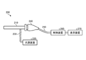
- FIG. 8 is a diagram showing a configuration of a medical observation system according to a modified example.
- the endoscope device 200 will be described as a medical observation system according to a modified example.
- the endoscope device 200 includes an insertion unit 210, a light source device 220, a light guide 230, a camera head 240, a cable 250, a control device 260, and a display device 270.
- the insertion portion 210 and the camera head 240 correspond to the microscope portion.
- a support portion (support arm) for supporting the endoscope device 200 may be provided.
- the insertion portion 210 has an elongated shape and includes an optical system that collects incident light inside.
- the tip of the insertion portion 210 is inserted into, for example, the body cavity of the patient.
- the rear end of the insertion portion 210 is detachably connected to the camera head 240. Further, the insertion portion 210 is connected to the light source device 220 via the light guide 230, and light is supplied from the light source device 220.
- the depth map information detects the subject distance from the position of the image sensor to the corresponding position on the observation target corresponding to the pixel position in the captured image for each pixel position, which is linked to the optical information of the insertion unit 201. This is the information that was given.
- the endoscope device 200 may change the direction of the line of sight for observation during use (during surgery). Therefore, when generating depth map information in the endoscope device 200, motion parallax or SLAM (Simultaneously Localization and Mapping) may be used. Further, the depth map information may be generated by controlling the support portion that supports the endoscope and imaging the surgical portion from a plurality of viewpoints.
- the light source device 220 is connected to the insertion portion 210 via the light guide 230.
- the light source device 220 supplies light to the insertion portion 210 via the light guide 230.
- the light supplied to the insertion portion 210 is emitted from the tip of the insertion portion 210 and irradiates an observation target such as a tissue in the body cavity of the patient. Then, the reflected light from the observation target is collected by the optical system in the insertion portion 210.
- the camera head 240 has a configuration corresponding to the above-mentioned imaging unit 71, and has a function of imaging an observation target.
- an image sensor, a lens, and the like are housed in a housing constituting the camera head 240.
- the camera head 240 is connected to the control device 260 via a cable 250.
- the camera head 240 images the observation target by photoelectrically converting the reflected light from the observation target collected by the insertion unit 210, and outputs the image signal obtained by the imaging to the control device 260 via the cable 250. do.
- the control device 260 controls the camera head 240, performs a predetermined process on the image signal output from the camera head 240, and then outputs the image signal to the display device 270.
- the control device 260 includes an image processing unit 31, an input unit 32, an output unit 33, a control unit 34, and a storage unit 35, and divides a subject image vibrating at different frequencies in the image. , After performing blur correction individually for each, combine them to generate an image.
- the display device 270 receives the image data generated by the control device 260 and displays the image corresponding to the image data.
- the display device 270 includes, for example, a display panel made of a CRT, a liquid crystal display, or an organic EL.
- subject images vibrating (blurring) at different frequencies are divided in the image, each is individually subjected to blur correction, and then combined to form an image. Is generated, so that it is possible to appropriately perform blur correction of an image in which a plurality of subjects are captured.
- Various inventions can be formed by appropriately combining a plurality of components disclosed in the medical observation system according to the embodiment of the present disclosure described above. For example, some components may be deleted from all the components described in the medical observation system according to the embodiment of the present disclosure described above. Further, the components described in the medical observation system according to the embodiment of the present disclosure described above may be appropriately combined.
- the above-mentioned "part” can be read as “means” or "circuit".
- the control unit can be read as a control means or a control circuit.
- the program to be executed by the medical observation system is a CD-ROM, a flexible disk (FD), a CD-R, or a DVD (Digital) in an installable format or an executable format file data. It is provided by being recorded on a computer-readable recording medium such as a Versatile Disk), a USB medium, or a flash memory.
- the program to be executed by the medical observation system may be stored on a computer connected to a network such as the Internet and provided by downloading via the network. ..
- the present technology can also have the following configurations.
- a dividing part that divides at least one subject image existing in the image, A detection unit that detects blurring of the subject image divided by the division unit, A subject image divided by the divided unit, a correction unit that corrects the blur of the subject image based on the blur detected by the detection unit, and a correction unit.
- a compositing unit that synthesizes the corrected subject image and the background image formed by the area other than the subject image, Medical image processing device including.
- the dividing unit divides the subject image based on the depth map information in which the distance between the image capturing unit that captures the image and the subject and the position of the image are associated with each other.
- the synthesis part The subject image is magnified at a preset magnification. Combining the enlarged subject image with the background image, The medical image processing apparatus according to (1) or (2) above.
- (4) There are a plurality of subject images in the image, The dividing portion divides the plurality of subject images and divides the plurality of subject images.
- the detection unit detects blurring for each subject image with respect to the plurality of subject images divided by the division unit.
- the correction unit corrects the blur of each subject image based on each subject image divided by the division unit and the blur detected by the detection unit with respect to each subject image.
- the compositing unit synthesizes each corrected subject image and a background image formed by regions other than the plurality of subject images.
- the medical image processing apparatus according to any one of (1) to (3) above.
- An imaging unit that captures the patient's surgical site on the operating table and outputs a video signal, A dividing unit that divides at least one subject image existing in the image generated based on the video signal, and a dividing unit.
- a detection unit that detects blurring of the subject image divided by the division unit, A subject image divided by the divided unit, a correction unit that corrects the blur of the subject image based on the blur detected by the detection unit, and a correction unit.
- a compositing unit that synthesizes the corrected subject image and the background image formed by the area other than the subject image, Medical observation system equipped with.
- the dividing unit divides the subject image based on the depth map information in which the distance between the image capturing unit that captures the image and the subject and the position of the image are associated with each other.
- the synthesis part The subject image is magnified at a preset magnification. Combining the enlarged subject image with the background image, The medical observation system according to (5) or (6) above.
- the dividing portion divides the plurality of subject images and divides the plurality of subject images.
- the detection unit detects blurring for each subject image with respect to the plurality of subject images divided by the division unit.
- the correction unit corrects the blur of each subject image based on each subject image divided by the division unit and the blur detected by the detection unit with respect to each subject image.
- the compositing unit synthesizes each corrected subject image and a background image formed by regions other than the plurality of subject images.
- the medical observation system according to any one of (5) to (7) above.
- the imaging unit is a microscope unit that photographs the surgical site of the patient. A support portion that supports the microscope portion is further provided.
- the medical observation system according to any one of (5) to (8) above.
- the imaging unit is an endoscope that photographs the surgical site of the patient.
- the medical observation system according to any one of (5) to (8) above.
- the medical image processing device and the medical observation system according to the present invention are useful for appropriately performing blur correction of an image in which a plurality of subjects are captured.
- Microscope device 3 260 Control device 4, 270 Display device 5 Base part 6 Support part 7 Microscope part 8, 220 Light source device 11 1st joint part 12 2nd joint part 13 3rd joint part 14 4th Joint part 15 5th joint part 16 6th joint part 21 1st arm part 22 2nd arm part 23 3rd arm part 24 4th arm part 25 5th arm part 31 Image processing part 32 Input part 33 Output part 34 Control part 35 Storage unit 71 Imaging unit 81 Light source cable 200 Endoscope device 210 Insertion unit 230 Light guide 240 Camera head 250 Cable 311 Signal processing unit 312 Division unit 313 Detection unit 314 Correction unit 315 Synthesis unit
Landscapes
- Health & Medical Sciences (AREA)
- Physics & Mathematics (AREA)
- Surgery (AREA)
- General Physics & Mathematics (AREA)
- Engineering & Computer Science (AREA)
- General Health & Medical Sciences (AREA)
- Life Sciences & Earth Sciences (AREA)
- Theoretical Computer Science (AREA)
- Nuclear Medicine, Radiotherapy & Molecular Imaging (AREA)
- Oral & Maxillofacial Surgery (AREA)
- Biomedical Technology (AREA)
- Heart & Thoracic Surgery (AREA)
- Medical Informatics (AREA)
- Molecular Biology (AREA)
- Animal Behavior & Ethology (AREA)
- Pathology (AREA)
- Public Health (AREA)
- Veterinary Medicine (AREA)
- Chemical & Material Sciences (AREA)
- Analytical Chemistry (AREA)
- Optics & Photonics (AREA)
- Microscoopes, Condenser (AREA)
- Image Processing (AREA)
Priority Applications (4)
| Application Number | Priority Date | Filing Date | Title |
|---|---|---|---|
| US17/795,871 US20230090615A1 (en) | 2020-03-11 | 2021-02-18 | Medical image processing device and medical observation system |
| JP2022505884A JPWO2021182066A1 (cg-RX-API-DMAC7.html) | 2020-03-11 | 2021-02-18 | |
| CN202180012228.0A CN115052551A (zh) | 2020-03-11 | 2021-02-18 | 医疗图像处理装置和医疗观察系统 |
| EP21768638.5A EP4094714A4 (en) | 2020-03-11 | 2021-02-18 | Medical image processing device and medical observation system |
Applications Claiming Priority (2)
| Application Number | Priority Date | Filing Date | Title |
|---|---|---|---|
| JP2020042474 | 2020-03-11 | ||
| JP2020-042474 | 2020-03-11 |
Publications (1)
| Publication Number | Publication Date |
|---|---|
| WO2021182066A1 true WO2021182066A1 (ja) | 2021-09-16 |
Family
ID=77671664
Family Applications (1)
| Application Number | Title | Priority Date | Filing Date |
|---|---|---|---|
| PCT/JP2021/006220 Ceased WO2021182066A1 (ja) | 2020-03-11 | 2021-02-18 | 医療用画像処理装置および医療用観察システム |
Country Status (5)
| Country | Link |
|---|---|
| US (1) | US20230090615A1 (cg-RX-API-DMAC7.html) |
| EP (1) | EP4094714A4 (cg-RX-API-DMAC7.html) |
| JP (1) | JPWO2021182066A1 (cg-RX-API-DMAC7.html) |
| CN (1) | CN115052551A (cg-RX-API-DMAC7.html) |
| WO (1) | WO2021182066A1 (cg-RX-API-DMAC7.html) |
Citations (7)
| Publication number | Priority date | Publication date | Assignee | Title |
|---|---|---|---|---|
| WO2006064751A1 (ja) * | 2004-12-16 | 2006-06-22 | Matsushita Electric Industrial Co., Ltd. | 複眼撮像装置 |
| JP2009017223A (ja) * | 2007-07-04 | 2009-01-22 | Sony Corp | 撮影装置、画像処理装置、これらにおける画像処理方法およびプログラム |
| JP2014017839A (ja) | 2000-04-04 | 2014-01-30 | Smith & Nephew Inc | 動きのアーティファクトを自動補正する方法およびシステム |
| WO2018003503A1 (ja) * | 2016-06-28 | 2018-01-04 | ソニー株式会社 | 画像処理装置および画像処理方法、並びに医療用撮像システム |
| WO2018211709A1 (ja) * | 2017-05-19 | 2018-11-22 | オリンパス株式会社 | ブレ補正装置、内視鏡装置及びブレ補正方法 |
| JP2019176249A (ja) * | 2018-03-27 | 2019-10-10 | オリンパス株式会社 | 画像処理装置、画像処理方法、画像処理プログラム及び撮像装置 |
| WO2020009127A1 (ja) * | 2018-07-06 | 2020-01-09 | ソニー株式会社 | 医療用観察システム、医療用観察装置、及び医療用観察装置の駆動方法 |
Family Cites Families (16)
| Publication number | Priority date | Publication date | Assignee | Title |
|---|---|---|---|---|
| JP2003018604A (ja) * | 2001-07-04 | 2003-01-17 | Matsushita Electric Ind Co Ltd | 画像信号符号化方法、画像信号符号化装置および記録媒体 |
| US7391895B2 (en) * | 2003-07-24 | 2008-06-24 | Carestream Health, Inc. | Method of segmenting a radiographic image into diagnostically relevant and diagnostically irrelevant regions |
| JP2005309560A (ja) * | 2004-04-19 | 2005-11-04 | Fuji Photo Film Co Ltd | 画像処理方法および装置並びにプログラム |
| JP4342493B2 (ja) * | 2005-09-22 | 2009-10-14 | 三洋電機株式会社 | 手ぶれ補正装置 |
| JP5105550B2 (ja) * | 2009-03-19 | 2012-12-26 | カシオ計算機株式会社 | 画像合成装置及びプログラム |
| JP5562808B2 (ja) * | 2010-11-11 | 2014-07-30 | オリンパス株式会社 | 内視鏡装置及びプログラム |
| JP5002702B2 (ja) * | 2010-12-03 | 2012-08-15 | 株式会社東芝 | 視差画像生成装置、立体映像表示装置及び視差画像生成方法 |
| WO2012075631A1 (en) * | 2010-12-08 | 2012-06-14 | Industrial Technology Research Institute | Methods for generating stereoscopic views from monoscopic endoscope images and systems using the same |
| JP5999359B2 (ja) * | 2013-01-30 | 2016-09-28 | 富士ゼロックス株式会社 | 画像処理装置及び画像処理プログラム |
| JP6041836B2 (ja) * | 2014-07-30 | 2016-12-14 | 京セラドキュメントソリューションズ株式会社 | 画像処理装置および画像処理プログラム |
| JP2016063248A (ja) * | 2014-09-12 | 2016-04-25 | 株式会社東芝 | 画像処理装置および画像処理方法 |
| WO2017169139A1 (ja) * | 2016-03-29 | 2017-10-05 | ソニー株式会社 | 画像処理装置、画像処理方法及び医療システム |
| US10904437B2 (en) * | 2017-03-16 | 2021-01-26 | Sony Corporation | Control apparatus and control method |
| JP7062506B2 (ja) * | 2018-05-02 | 2022-05-06 | キヤノン株式会社 | 画像処理装置、画像処理方法、およびプログラム |
| US10917571B2 (en) * | 2018-11-05 | 2021-02-09 | Sony Corporation | Image capture device control based on determination of blur value of objects in images |
| US20200305828A1 (en) * | 2019-03-27 | 2020-10-01 | Shimadzu Corporation | Radiation Image Processing Apparatus and Radiation Image Processing Method |
-
2021
- 2021-02-18 JP JP2022505884A patent/JPWO2021182066A1/ja active Pending
- 2021-02-18 US US17/795,871 patent/US20230090615A1/en not_active Abandoned
- 2021-02-18 EP EP21768638.5A patent/EP4094714A4/en not_active Withdrawn
- 2021-02-18 WO PCT/JP2021/006220 patent/WO2021182066A1/ja not_active Ceased
- 2021-02-18 CN CN202180012228.0A patent/CN115052551A/zh not_active Withdrawn
Patent Citations (7)
| Publication number | Priority date | Publication date | Assignee | Title |
|---|---|---|---|---|
| JP2014017839A (ja) | 2000-04-04 | 2014-01-30 | Smith & Nephew Inc | 動きのアーティファクトを自動補正する方法およびシステム |
| WO2006064751A1 (ja) * | 2004-12-16 | 2006-06-22 | Matsushita Electric Industrial Co., Ltd. | 複眼撮像装置 |
| JP2009017223A (ja) * | 2007-07-04 | 2009-01-22 | Sony Corp | 撮影装置、画像処理装置、これらにおける画像処理方法およびプログラム |
| WO2018003503A1 (ja) * | 2016-06-28 | 2018-01-04 | ソニー株式会社 | 画像処理装置および画像処理方法、並びに医療用撮像システム |
| WO2018211709A1 (ja) * | 2017-05-19 | 2018-11-22 | オリンパス株式会社 | ブレ補正装置、内視鏡装置及びブレ補正方法 |
| JP2019176249A (ja) * | 2018-03-27 | 2019-10-10 | オリンパス株式会社 | 画像処理装置、画像処理方法、画像処理プログラム及び撮像装置 |
| WO2020009127A1 (ja) * | 2018-07-06 | 2020-01-09 | ソニー株式会社 | 医療用観察システム、医療用観察装置、及び医療用観察装置の駆動方法 |
Non-Patent Citations (1)
| Title |
|---|
| See also references of EP4094714A4 |
Also Published As
| Publication number | Publication date |
|---|---|
| CN115052551A (zh) | 2022-09-13 |
| EP4094714A1 (en) | 2022-11-30 |
| EP4094714A4 (en) | 2023-08-02 |
| US20230090615A1 (en) | 2023-03-23 |
| JPWO2021182066A1 (cg-RX-API-DMAC7.html) | 2021-09-16 |
Similar Documents
| Publication | Publication Date | Title |
|---|---|---|
| JP7074065B2 (ja) | 医療用画像処理装置、医療用画像処理方法、プログラム | |
| JP7211364B2 (ja) | 撮像装置、画像生成方法、プログラム | |
| WO2018123613A1 (ja) | 医療用画像処理装置、医療用画像処理方法、プログラム | |
| US10609354B2 (en) | Medical image processing device, system, method, and program | |
| WO2018021035A1 (ja) | 画像処理装置および方法、内視鏡システム、並びにプログラム | |
| JP2011115252A (ja) | 医療用プローブ、および医療用観察システム | |
| JP2019084334A (ja) | 医療用保持装置、医療用アームシステム、及びドレープ装着機構 | |
| JP7235035B2 (ja) | 映像信号処理装置、映像信号処理方法および撮像装置 | |
| JPWO2018180573A1 (ja) | 手術用画像処理装置、画像処理方法、及び、手術システム | |
| WO2020203265A1 (ja) | 映像信号処理装置、映像信号処理方法および撮像装置 | |
| JP2017176318A (ja) | 医療用立体観察装置、医療用立体観察方法、プログラム、及び医療用立体観察システム | |
| JP2019004978A (ja) | 手術システムおよび手術用撮像装置 | |
| JP7207296B2 (ja) | 撮像装置とフォーカス制御方法およびフォーカス判定方法 | |
| WO2021020132A1 (ja) | 内視鏡手術システム、画像処理装置、および画像処理方法 | |
| JP2014228851A (ja) | 内視鏡装置、画像取得方法および画像取得プログラム | |
| JPWO2020084999A1 (ja) | 画像処理装置、および画像処理方法、並びにプログラム | |
| JP7092111B2 (ja) | 撮像装置、映像信号処理装置および映像信号処理方法 | |
| US20230090615A1 (en) | Medical image processing device and medical observation system | |
| WO2021049220A1 (ja) | 医療用支持アーム、及び医療用システム | |
| WO2018168571A1 (ja) | 撮像装置、映像信号処理装置および映像信号処理方法 | |
| US20210228061A1 (en) | Medical observation system, medical observation apparatus, and drive method of medical observation apparatus | |
| WO2018043205A1 (ja) | 医療用画像処理装置、医療用画像処理方法、プログラム | |
| WO2022080008A1 (ja) | 医療用画像処理装置及び医療用観察システム | |
| WO2017082091A1 (ja) | 手術システム、手術用制御方法、およびプログラム | |
| JP2020130884A (ja) | 医療用画像処理装置、画像処理方法およびプログラム |
Legal Events
| Date | Code | Title | Description |
|---|---|---|---|
| 121 | Ep: the epo has been informed by wipo that ep was designated in this application |
Ref document number: 21768638 Country of ref document: EP Kind code of ref document: A1 |
|
| WWE | Wipo information: entry into national phase |
Ref document number: 21768638 Country of ref document: EP |
|
| ENP | Entry into the national phase |
Ref document number: 2021768638 Country of ref document: EP Effective date: 20220821 |
|
| ENP | Entry into the national phase |
Ref document number: 2022505884 Country of ref document: JP Kind code of ref document: A |
|
| NENP | Non-entry into the national phase |
Ref country code: DE |
|
| WWW | Wipo information: withdrawn in national office |
Ref document number: 2021768638 Country of ref document: EP |