WO2021181964A1 - 電極付きバンド、及び、生体装着機器 - Google Patents
電極付きバンド、及び、生体装着機器 Download PDFInfo
- Publication number
- WO2021181964A1 WO2021181964A1 PCT/JP2021/004150 JP2021004150W WO2021181964A1 WO 2021181964 A1 WO2021181964 A1 WO 2021181964A1 JP 2021004150 W JP2021004150 W JP 2021004150W WO 2021181964 A1 WO2021181964 A1 WO 2021181964A1
- Authority
- WO
- WIPO (PCT)
- Prior art keywords
- band
- longitudinal direction
- electrodes
- elasticity
- electrode
- Prior art date
- Legal status (The legal status is an assumption and is not a legal conclusion. Google has not performed a legal analysis and makes no representation as to the accuracy of the status listed.)
- Ceased
Links
Images


Classifications
-
- A—HUMAN NECESSITIES
- A61—MEDICAL OR VETERINARY SCIENCE; HYGIENE
- A61B—DIAGNOSIS; SURGERY; IDENTIFICATION
- A61B5/00—Measuring for diagnostic purposes; Identification of persons
- A61B5/68—Arrangements of detecting, measuring or recording means, e.g. sensors, in relation to patient
- A61B5/6801—Arrangements of detecting, measuring or recording means, e.g. sensors, in relation to patient specially adapted to be attached to or worn on the body surface
- A61B5/683—Means for maintaining contact with the body
- A61B5/6831—Straps, bands or harnesses
-
- A—HUMAN NECESSITIES
- A61—MEDICAL OR VETERINARY SCIENCE; HYGIENE
- A61B—DIAGNOSIS; SURGERY; IDENTIFICATION
- A61B5/00—Measuring for diagnostic purposes; Identification of persons
- A61B5/24—Detecting, measuring or recording bioelectric or biomagnetic signals of the body or parts thereof
- A61B5/25—Bioelectric electrodes therefor
- A61B5/251—Means for maintaining electrode contact with the body
- A61B5/256—Wearable electrodes, e.g. having straps or bands
-
- A—HUMAN NECESSITIES
- A61—MEDICAL OR VETERINARY SCIENCE; HYGIENE
- A61B—DIAGNOSIS; SURGERY; IDENTIFICATION
- A61B5/00—Measuring for diagnostic purposes; Identification of persons
- A61B5/24—Detecting, measuring or recording bioelectric or biomagnetic signals of the body or parts thereof
- A61B5/316—Modalities, i.e. specific diagnostic methods
- A61B5/318—Heart-related electrical modalities, e.g. electrocardiography [ECG]
-
- A—HUMAN NECESSITIES
- A61—MEDICAL OR VETERINARY SCIENCE; HYGIENE
- A61B—DIAGNOSIS; SURGERY; IDENTIFICATION
- A61B5/00—Measuring for diagnostic purposes; Identification of persons
- A61B5/68—Arrangements of detecting, measuring or recording means, e.g. sensors, in relation to patient
- A61B5/6801—Arrangements of detecting, measuring or recording means, e.g. sensors, in relation to patient specially adapted to be attached to or worn on the body surface
- A61B5/6813—Specially adapted to be attached to a specific body part
- A61B5/6824—Arm or wrist
-
- A—HUMAN NECESSITIES
- A61—MEDICAL OR VETERINARY SCIENCE; HYGIENE
- A61B—DIAGNOSIS; SURGERY; IDENTIFICATION
- A61B2562/00—Details of sensors; Constructional details of sensor housings or probes; Accessories for sensors
- A61B2562/16—Details of sensor housings or probes; Details of structural supports for sensors
- A61B2562/164—Details of sensor housings or probes; Details of structural supports for sensors the sensor is mounted in or on a conformable substrate or carrier
-
- A—HUMAN NECESSITIES
- A61—MEDICAL OR VETERINARY SCIENCE; HYGIENE
- A61B—DIAGNOSIS; SURGERY; IDENTIFICATION
- A61B5/00—Measuring for diagnostic purposes; Identification of persons
- A61B5/02—Detecting, measuring or recording for evaluating the cardiovascular system, e.g. pulse, heart rate, blood pressure or blood flow
- A61B5/024—Measuring pulse rate or heart rate
- A61B5/02438—Measuring pulse rate or heart rate with portable devices, e.g. worn by the patient
Definitions
- One aspect of the present invention relates to a band with electrodes and a biofitting device.
- the heart rate measuring device of Patent Document 1 detects an electrocardiographic signal while being wrapped around the chest by a band.
- the heart rate measuring device is made circular, the elastic strap and the non-elastic belt on which the electrodes are arranged are connected in the circumferential direction of the band by using metal fittings.
- the electrocardiographic signal detection in the chest a large potential difference can be obtained by arranging the electrodes across the heart, so that the electrode spacing in the non-stretchable belt may be relatively short. Therefore, the heart rate measuring device can be provided with a relatively long stretchable portion, and the length of the strap can be easily adjusted.
- a biological device such as a heart rate measuring device may be attached to a limb (upper limb or lower limb) using a band.
- a band At that time, if the number of electrodes arranged in the band is increased or the area of each electrode is increased in order to detect a smaller potential difference, it may be difficult to incorporate a portion having elasticity in the circumferential direction of the band. There is. In this case, after the bio-mounted device is attached to the user by the band, the length of the band does not follow the increase in the diameter (perimeter) of the part where the bio-mounted device is attached, which may cause discomfort to the user. There is.
- An object of the present invention is to provide a band with electrodes and a biofitting device capable of suppressing causing discomfort to a user when mounted at an appropriate position.
- the present invention may adopt the following configuration in order to solve the above-mentioned problems.
- the band with electrodes is a band-shaped first band portion extending along the longitudinal direction and a second band portion provided in the first direction along the longitudinal direction with respect to the first band portion and extending along the longitudinal direction. It has a band part.
- the second band portion has a first telescopic portion having electrical insulation, a conductive electrode, a second telescopic portion, a ring-shaped ring member, a folded portion, and a joint portion.
- the first stretchable portion has a band shape having a first plane and a second plane opposite to the first plane, and has a first stretchability along the longitudinal direction.
- the electrode is provided on the first surface of the first telescopic portion.
- the second stretchable portion is overlapped with the first stretchable portion on the side of the second surface of the first stretchable portion, and has a band shape.
- the ring member is provided at a position that becomes a band end along the longitudinal direction of the second band portion, and can be connected to the first band portion.
- the folded portion is provided between the first elastic portion and the second elastic portion, and is folded back in the ring member so that the first elastic portion and the second elastic portion overlap each other.
- the joint portion joins the second surface of the first expansion / contraction portion and the second expansion / contraction portion.
- the longitudinal direction is a direction along the extending direction (circumferential direction) of the band.
- a second stretchable portion having a higher elasticity than the first stretchable portion is superposed on the second surface of the first stretchable portion provided with an electrode on the first surface.
- the first expansion / contraction portion and the second expansion / contraction portion are continuous at the folded portion between the first expansion / contraction portion and the second expansion / contraction portion.
- the second telescopic portion in the second band portion expands and contracts in the longitudinal direction (circumferential direction) according to the movement of the living body at the position where the band is attached.
- the band with electrodes is adjusted in elasticity in one second band portion according to the movement of the user, so that the band is prevented from causing discomfort to the user when it is attached at an appropriate position. It is possible.
- the position where the band is attached is preferably the limbs (upper limbs or lower limbs), but may be the chest, abdomen, waist, or the like. Since the electrodes are provided on the first surface of the first telescopic portion, which is harder to expand and contract than the second telescopic portion, the positional relationship between the living body and the electrodes is maintained in a fixed state for the user who wears the band.
- Signal detection using electrodes refers to obtaining signals from a living body such as a heartbeat and an electric signal that becomes an electrocardiogram when it is transmitted as a waveform transmitted through the atrium and the ventricle. This is an “inspection” using electrodes.
- “Treatment” using electrodes means, for example, applying a weak electric current of 1200 Hz or less to the surface of the skin and stimulating the current to eliminate stiffness in the muscles of the affected area.
- the first stretchable portion has a third stretchability that stretches more along the longitudinal direction than the first stretchable portion, and is fixed to a base portion that forms a second surface and a third stretchable portion. It has a fourth elasticity that is more difficult to expand and contract along the longitudinal direction, and adjusts the elasticity of the first expansion and contraction portion along the longitudinal direction to a state that has the first elasticity, and adjusts the elasticity to form the first surface. It is preferable to have a member. With such a configuration, the elasticity in the longitudinal direction of the first expansion / contraction portion of the second band portion can be adjusted to have the first elasticity by the base portion and the elasticity adjusting member.
- the first stretchable portion has little stretchability or non-stretchability along the longitudinal direction.
- the first telescopic portion is difficult to expand and contract, and the positional relationship between the living body and the electrode can be more reliably maintained in a state where the electrode is arranged in the first elastic portion.
- the folded portion has first elasticity in the longitudinal direction.
- the folded portion can be integrally formed with the same configuration as the first telescopic portion.
- it is preferred that the folded portion has a second stretch in the longitudinal direction.
- the folded portion can be integrally formed with the same configuration as the second telescopic portion.
- the first band portion is folded back by a ring member toward a position outside the first band portion to adjust the length of the first band portion, and is removable to the outside of the first band portion. It is preferable to have a connecting part. With the first band portion, it is possible to perform initial adjustment of the peripheral length of the band when attaching the band for the living body wearing device to be worn on the living body.
- the first telescopic portion of the second band portion includes a wiring that electrically connects the electrode and the main body portion provided on the band with electrodes. Since the wiring is provided in the first expansion / contraction portion, which has lower elasticity than the second expansion / contraction portion, it is possible to suppress the application of a load in the longitudinal direction of the wiring.
- the bio-mounted device has a band with electrodes and a main body portion provided between the first band portion and the second band portion of the band and incorporating a control substrate electrically connected to the electrodes. .. Therefore, it is possible to provide a bio-mounted device capable of suppressing causing discomfort to the user in a state of being mounted at an appropriate position.
- a main body having a sensor, a transducer, or the like can be attached and used at an appropriate position on the band with electrodes. Therefore, the main body portion having a desired function can be attached to the band with electrodes and used.
- a main body having a function of measuring a heartbeat can be attached to one band to measure the heartbeat.
- An electrocardiographic signal can be detected by attaching a main body for detecting an electrocardiographic signal to one band instead of the main body having a function of measuring a heartbeat.
- a main body having a function of performing low frequency treatment can be attached to one band to perform low frequency treatment. In this way, various main bodies can be attached to one band and used.
- a band with electrodes and a biofitting device capable of suppressing causing discomfort to the user in a state of being mounted at an appropriate position.
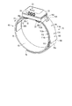
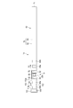
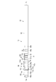
- FIG. 1 is a schematic perspective view showing a bio-mounted device according to the first embodiment.
- FIG. 2 is a schematic perspective view showing a bio-mounted device viewed from a direction different from that of FIG.
- FIG. 3 is a schematic block diagram showing a bio-mounted device according to the first embodiment.
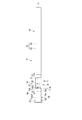
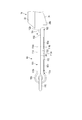
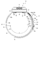
- FIG. 4 is a schematic top view showing a biofitting device according to the first embodiment.
- FIG. 5 is a schematic view of the bio-mounted device in FIG. 4 as viewed from the direction indicated by the arrow V.
- FIG. 6 is a schematic view of the bio-mounted device in FIG. 5 as viewed from the direction indicated by the arrow VI.
- FIG. 7 is an enlarged view of the position indicated by reference numeral VII in FIG. FIG.
- FIG. 8 is a schematic view showing a biofitting device according to the first embodiment.
- FIG. 9 is a schematic view showing that when the user is in the anatomical position, the main body of the biofitting device according to the first embodiment is attached so as to face the front of the user.
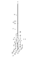
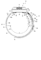
- FIG. 10 is a schematic top view showing the bio-mounted device according to the second embodiment.
- FIG. 11 is a schematic view of the bio-mounted device in FIG. 10 as viewed from the direction indicated by the arrow XI.
- FIG. 12 is a schematic view of the bio-mounted device in FIG. 11 as viewed from the direction indicated by the arrow XII.
- FIG. 13 is a schematic view showing a biofitting device according to the second embodiment.
- FIG. 14 is a schematic view showing a biofitting device according to a third embodiment.
- FIG. 15 is a schematic view showing a band with electrodes for a bio-mounted device according to a fourth embodiment.
- the electrode-attached band 12 including the electrodes 68a and 68b is attached to an appropriate position such as an appropriate limb (upper limb or lower limb), chest, abdomen, and waist of the user's body B.
- the band 12 may be attached to the user's head.
- the band 12 is used together with the main body 14.
- the band 12 is a second band in which a first band portion 62 whose length is largely adjusted (initially adjusted) according to a user's mounting position, and a first elastic portion 112 and a second elastic portion 114 having different elasticity are arranged so as to overlap each other. It has a band portion 64.
- the folded portion 106 and the ring member 110 between the first expansion / contraction portion 112 and the second expansion / contraction portion 114 move in the circumferential direction (longitudinal direction) of the band 12 according to the movement of the user at the position where the band 12 is attached to the user. Moving. Therefore, the band 12 allows the movement of the user in the second band portion 64 and prevents it from being hindered.
- the band 12 and the biofitting device 10 having the band 12 allow the user to move at the position where the band 12 is attached, thereby suppressing causing discomfort to the user.
- the bio-mounted device 10 is configured to detect signals from the living body such as heartbeat, electrocardiographic signal, and myoelectricity. Further, the living body wearing device 10 may be configured to perform treatment by applying an electric signal such as a low frequency to the living body.
- the electrode-attached band 12 used together with the bio-mounted device 10 and the bio-mounted device 10 will be described with reference to FIGS. 1 to 9.
- a case where the biological device 10 measures a heartbeat and an electrocardiographic signal will be described as an example.
- the bio-mounted device 10 has an electrode-attached band (belt) 12 for the bio-mounted device 10 and a main body portion 14 provided on the band 12.
- the band 12 of the biofitting device 10 is fixed to the main body 14.
- the bio-attached device 10 including the band 12 and the main body 14 is wrapped around and attached to the user (living body), for example, the limbs (upper limbs or lower limbs) by the band 12.
- the band 12 is formed to a length that can be attached to the user's limbs.
- the biofitting device 10 is formed in a size and weight that can be easily operated by the user while being attached to the user's limbs by the band 12.
- the band 12 is formed to a length that is attached to the user's chest, lumbar region, or head.
- the biofitting device 10 is attached to the upper left arm of the user.
- the main body 14 includes a frame (exterior body) 22, an operation unit 24 provided on the frame 22, a display unit 26 provided on the frame 22, and a pair of support portions 28a and 28b provided on the frame 22.
- the frame 22 is made of a material having electrical insulation. With the biological attachment device 10 attached to the upper left arm of the user, the support portions 28a and 28b are on the biological side (back side) with respect to the frame 22, and the operation portion 24 is in a position where it can be operated by the fingers of the user's hand or the like.
- the display unit 26 is located at a position visible to the user, that is, on the side opposite to the living body (front surface side).
- the support portions 28a and 28b are formed in a substantially wedge shape, for example.
- the support portions 28a and 28b project from the back surface of the frame 22 and form a part of the annular body when attached to the upper left arm of the living body in cooperation with the frame 22 and the band 12.
- the support portions 28a and 28b are separated from each other in the longitudinal direction of the band 12.
- the longitudinal direction is a direction along the extending direction (circumferential direction) of the band 12 with respect to the main body portion 14.
- the direction in which the first band portion (longitudinal band) 62 described later extends from the main body portion 14 is the first direction D1
- the direction in which the second band portion (short band) 64 described later extends from the main body portion 14 is defined as the first direction D1.
- the second direction is D2.
- the back surface of the frame 22 between the support portions 28a and 28b is flat.
- the support portions 28a and 28b are inclined with respect to the back surface of the frame 22 so as to easily contact the upper left arm of the living body.
- the support portion 28a, the back surface of the frame 22, and the support portion 28b are formed in a substantially arc shape as a whole.
- the support portions 28a and 28b are made of a flexible material such as a rubber material or a resin material that can be elastically deformed.
- the first main body electrode 30 is fixed to the back surface of the frame 22 of the main body 14.
- the second main body electrode 32 is fixed to one of the support portions 28a.
- a third main body electrode 34 is fixed to the other support portion 28b.
- the first to third main body electrodes 30, 32, 34 are used as a sensor or a transducer for detecting an electric potential.
- the first main body electrode 30, the second main body electrode 32, and the third main body electrode 34 are formed in a plate shape by, for example, a conductive metal plate or a conductive elastomer, and are separated from each other.
- the main body portion 14 has three main body electrodes 30, 32, 34 will be described.
- the three main body electrodes 30, 32, and 34 may be electrically connected to each other and formed so as to be equated as one electrode, or may be formed as one plate-shaped electrode.
- the main body unit 14 includes a control unit 42, an electrocardiogram information generation unit 44, an electrocardiogram generation unit 46, a communication unit 48, and a battery 50.
- the main body portion 14 further includes a light emitting unit 52, a light receiving unit 54, and a heartbeat information generating unit 56.
- the control unit 42, the electrocardiogram information generation unit 44, the electrocardiogram generation unit 46, the communication unit 48, the battery 50, the light projecting unit 52, the light receiving unit 54, and the heartbeat information generation unit 56 are mounted on the control board 40 built in the frame 22. It is provided.
- the control board 40 is further provided with an operation unit 24 and a display unit 26.
- the control unit 42 includes an operation unit 24, a display unit 26, a first main body electrode 30, a second main body electrode 32, a third main body electrode 34, an electrocardiogram information generation unit 44, an electrocardiogram generation unit 46, a communication unit 48, and a light projecting unit.
- the 52, the light receiving unit 54, and the heartbeat information generation unit 56 are electrically connected, for example.
- the control unit 42 is electrically connected to the first to fourth band electrodes (biological signal detection units) 66a, 66b, 68a, 68b, which will be described later.
- the control unit 42 includes an operation unit 24, a display unit 26, a first main body electrode 30, a second main body electrode 32, a third main body electrode 34, an electrocardiogram information generation unit 44, an electrocardiogram generation unit 46, a communication unit 48, and a light projecting unit 52.
- the light receiving unit 54, the heartbeat information generation unit 56, and the first to fourth band electrodes 66a, 66b, 68a, 68b can be controlled, respectively.
- the control unit 42 deploys a control program stored in a memory such as a ROM by, for example, one or a plurality of processors in the RAM according to the power from the battery 50, and the operation unit 24, the display unit 26, and the first main body electrode.
- a control program stored in a memory such as a ROM by, for example, one or a plurality of processors in the RAM according to the power from the battery 50, and the operation unit 24, the display unit 26, and the first main body electrode.
- a control program stored in a memory such as a ROM by, for example, one or a plurality of processors in the RAM according to the power from the battery 50, and the operation unit 24, the display unit 26, and the first main body electrode.
- 2nd main body electrode 32, 3rd main body electrode 34, electrocardiogram information generation unit 44, electrocardiogram generation unit 46, communication unit 48, light projection unit 52, light receiving unit 54, heartbeat information generation unit 56, and 1st to 1st Appropriate processing is performed on the 4-band electrode
- one or more processors read the program via the network, and the operation unit 24, the display unit 26, the first main body electrode 30, the second main body electrode 32, the third main body electrode 34, and the electrocardiogram information. Appropriate processing is executed for the generation unit 44, the electrocardiogram generation unit 46, the communication unit 48, the light projection unit 52, the light receiving unit 54, the heart rate information generation unit 56, and the first to fourth band electrodes 66a, 66b, 68a, 68b. do.
- the control unit 42 includes an operation unit 24, a display unit 26, a first main body electrode 30, a second main body electrode 32, a third main body electrode 34, an electrocardiogram information generation unit 44, an electrocardiogram generation unit 46, a communication unit 48, and a light projecting unit 52.
- the light receiving unit 54, the heartbeat information generation unit 56, and the first to fourth band electrodes 66a, 66b, 68a, 68b can be controlled by a circuit (for example, ASIC) that realizes one or more functions. ..
- the operation unit 24 has an operation button into which instructions such as power ON / OFF of the main body unit 14, measurement start, and measurement stop operations are input.
- the display unit 26 causes the user to recognize the operating state of the main body unit 14 (operating state of the control unit 42) by, for example, emitting light from an LED (Light Emitting Diode).
- the user can grasp the operating state of the main body unit 14 by recognizing the light emitting color, the light emitting pattern, and the like of the display unit 26 controlled by the control unit 42.
- the operating state is, for example, an indication that the power is turned on by the operation of the operation unit 24, that measurement is being performed using the main body unit 14, an appropriate signal is measured, and an external device is communicated using the communication unit 48. Including that the information is properly transmitted to.
- the display unit 26 may be formed as a screen for displaying electrocardiogram information such as a waveform generated by the electrocardiogram generation unit 46 and heartbeat information generated by the heartbeat information generation unit 56.
- electrocardiogram information such as a waveform generated by the electrocardiogram generation unit 46 and heartbeat information generated by the heartbeat information generation unit 56.
- An example of a screen is a liquid crystal display or an organic electroluminescence display.
- the operation unit 24 and the display unit 26 are formed as an integrated touch panel.
- the operation unit 24 converts the command into an electric signal by being operated by the user.
- the display unit 26 can display electrocardiogram information, heartbeat information, and other operating states of the control unit 42.
- the first to fourth band electrodes 66a, 66b, 68a, 68b are used, for example, as a sensor or a transducer for obtaining potential information.
- the electrocardiogram information generation unit 44 selectively uses a plurality of the first to third main body electrodes 30, 32, 34 and the first to fourth band electrodes 66a, 66b, 68a, 68b to obtain potential difference information. , Generate electrocardiogram information by signal processing.
- the electrocardiogram generation unit 46 generates information on the electrocardiogram based on the electrocardiogram information generated by the electrocardiogram information generation unit 44.
- the electrocardiogram information generated by the electrocardiogram information generation unit 44 and the information about the electrocardiogram generated by the electrocardiogram generation unit 46 are transmitted to the external device of the biofitting device 10 by the communication unit 48 controlled by the control unit 42 and stored in the external device. ..
- the external device is a data server, a PC, a smartphone or a tablet terminal. It is also preferable that the electrocardiogram information generated by the electrocardiogram information generation unit 44 and the information related to the electrocardiogram generated by the electrocardiogram generation unit 46 are stored in a storage unit (not shown) in the main body unit 14.
- the light projecting unit 52 can emit light having an appropriate wavelength toward the living body through the window unit 22a in the first main body electrode 30 on the back surface shown in FIG. 1 of the frame 22.
- the light receiving unit 54 can receive the reflected light of the light emitted from the light projecting unit 52 toward the living body through the window unit 22a.
- the heartbeat information generation unit 56 appropriately processes a signal to generate heartbeat information based on the information obtained by projecting light on the living body by the light emitting unit 52 and obtaining the reflected light from the living body by the light receiving unit 54 and performing photoelectric conversion. ..
- the heartbeat information generated by the heartbeat information generation unit 56 is transmitted to the external device of the biofitting device 10 by the communication unit 48 controlled by the control unit 42 and stored in the external device. It is also preferable that the heartbeat information generated by the heartbeat information generation unit 56 is stored in a storage unit (not shown) in the main body unit 14.
- the band 12 extends from the main body portion 14 in two directions D1 and D2 in opposite directions.
- the band 12 has a first band portion (first belt portion) 62 and a second band portion (second belt portion) 64.
- the first band portion 62 and the second band portion 64 are band-shaped (strap-shaped or strip-shaped) and extend along the longitudinal direction.
- Two band electrodes (first and second band electrodes) 66a and 66b are fixed to the first band portion 62.
- the second band electrode 66b fixed to the first band portion 62 may be removable from the first band portion 62. It is preferable that a plurality of electrodes 66a and 66b are arranged in the first band portion 62, but one may be used.
- Two band electrodes (third and fourth band electrodes) 68a and 68b are fixed to the second band portion 64.
- the fourth band electrode 68b fixed to the second band portion 64 may be removable from the second band portion 64. It is preferable that a plurality of electrodes 68a and 68b are arranged in the second band portion 64, but one may be used.
- the first band portion 62 not only the second band electrode 66b but also the first band electrode 66a may be removable.
- the fourth band electrode 68b but also the third band electrode 68a may be removable.
- the main body 14 is fixed to a desired position on the upper left arm, for example, by using the band 12.
- the lengths of the first band portion 62 and the second band portion 64 of the band 12 may be constant regardless of the user who assumes the attachment, or may be changed according to the user who assumes the attachment. For example, a lineup of bands 12 having lengths assuming adults, children, men, women, and the like may be used.
- the lengths of the first band portion 62 and the second band portion 64 of the band 12 may be the same length as when they are attached to the lower limbs instead of the upper limbs such as the upper left arm, and they are assumed to be attached. It may be changed according to the position.
- the first band portion 62 has one end 72, the other end 74, and an expansion / contraction portion (first band portion side expansion / contraction portion) 76.
- One end 72 of the first band portion 62 is supported by the main body portion 14. It is preferable that the first band portion 62 can be rotated at one end 72, for example, along the living body.
- the other end 74 of the first band portion 62 is an open end.
- the stretchable portion 76 of the first band portion 62 has the first stretchability that stretches and contracts along the longitudinal direction.
- the first stretchable stretchable portion 76 along the longitudinal direction of the first band portion 62 is substantially formed as a hard stretchable portion or a non-stretchable portion that hardly stretches along the longitudinal direction.
- the first stretchability of the first band portion 62 has substantially the same meaning as poor stretchability or non-stretchability.
- the stretchability in the width direction orthogonal to the longitudinal direction of the stretchable portion 76 of the first band portion 62 is substantially the same as, for example, the first stretchability.
- the first band portion 62 has a base material 82 having higher elasticity in the longitudinal direction than the first elasticity, and an elasticity adjusting member 84 fixed to the base material 82.
- the base material 82 expands and contracts more along the longitudinal direction per unit length than the first elasticity of the expansion and contraction portion 76.
- the base material 82 is made of cloth, for example.
- a stretch material such as polyurethane, cotton, or rubber can be used.
- the adjusting member 84 a material having lower elasticity along the longitudinal direction than the base material 82 is used.
- the adjusting member 84 is made of cloth, for example.
- a material having substantially non-stretchable or non-stretchable material is used.
- the base material 82 and the adjusting member 84 are formed long along the longitudinal direction.
- the base material 82 defines one end 72 and the other end 74 along the longitudinal direction.
- the length of the adjusting member 84 is slightly shorter than the length of the base material 82.
- the adjusting member 84 is fixed between one end 72 and the other end 74 of the base material 82.
- the base material 82 and the adjusting member 84 are sewn or affixed and fixed.
- the outer edge of the adjusting member 84 is inside the outer edge of the base material 82.
- the base material 82 is on the living body side when the living body wearing device 10 is attached to the living body.
- the adjusting member 84 is on the opposite side of the living body when attached to the living body.
- the base material 82 and the adjusting member 84 have flexibility.
- the base material 82 and the adjusting member 84 are made of a material having electrical insulation.
- the adjusting member 84 which is slightly shorter than the total length of the first band portion 62 and has lower elasticity than the base material 82, is fixed to the base material 82, so that the base material 82 expands and contracts as a whole. Elasticity decreases with respect to sex.
- the first stretchability in the longitudinal direction of the first band portion 62 is substantially the same as the stretchability in the longitudinal direction of the adjusting member 84, and has substantially low stretchability or non-stretchability.
- a hook-and-loop fastener for example, a hook-and-loop fastener is used. It is preferable to use a hook-and-loop fastener in which hooks and loops are mixed on the same surface.
- the length of the first band portion 62 is adjusted by being folded back at an appropriate portion where the base material 82 and the adjusting member 84 overlap each other and connected by contact between the surface fasteners of the adjusting member 84. Therefore, the hook-and-loop fastener of the adjusting member 84 of the first band portion 62 is folded back by the ring member 110 toward a position outside the first band portion 62, and the length of the first band portion 62 is adjusted. It is a connection portion that can be attached to and detached from the outside of the first band portion 62.
- the first band electrode 66a is fixed at a position close to the second main body electrode 32 in the base material 82 of the first band portion 62.
- the second band electrode 66b is fixed at a position of the base material 82 of the first band portion 62 that is separated from the second main body electrode 32 by the first band electrode 66a.
- the first band electrode 66a and the second band electrode 66b are adjacent to each other in the longitudinal direction.
- the first band electrode 66a and the second band electrode 66b are formed in a plate shape by a conductive metal plate or a conductive elastomer, and hardly extend in the longitudinal direction.
- the first band electrode 66a is electrically connected to the control unit 42 of the control board 40 of the main body unit 14 through the wiring 67a arranged in the first band unit 62.
- the second band electrode 66b is electrically connected to the control unit 42 of the control board 40 of the main body unit 14 through the wiring 67b arranged in the first band unit 62.
- the second band portion 64 includes a band-shaped band main body 100 and a ring-shaped ring member 110 provided at a position at a band end along the longitudinal direction of the second band portion 64. Has.
- the band body 100 has one end 102, the other end 104, a folded-back portion 106, and a fixed portion (joint portion) 108.
- the band body 100 is continuous between one end 102 and the other end 104.
- One end 102 of the band main body 100 is supported by the main body portion 14.
- the second band portion 64 can be rotated at one end 102, for example, along the living body.
- the band end of the second band portion 64 is located at the most distal position with respect to one end 102 of the band body 100 along the second direction D2 in the longitudinal direction.
- the band body 100 is folded back at the folded-back portion 106 at the ring member 110 at the position of the band end of the second band portion 64.
- the folded-back portion 106 is located at the most distal position with respect to one end 102 of the second band portion 64 along the second direction D2 in the longitudinal direction.
- the other end 104 of the second band portion 64 is located between the one end 102 and the folded portion 106 along the longitudinal direction.
- a fixing portion 108 is provided at the other end 104 of the second band portion 64.
- the fixing portion 108 is located proximal to the main body portion 14 with respect to the folded portion 106 along the longitudinal direction.
- the area between one end 102 of the band body 100 and the folded portion 106 is formed as a first expansion / contraction portion (first expansion / contraction region) 112.
- the area between the folded portion 106 and the other end 104 of the band body 100 is formed as a second expansion / contraction portion (second expansion / contraction region) 114.
- the first telescopic portion 112 and the second telescopic portion 114 are strip-shaped (strap-shaped or strip-shaped).
- a folded-back portion 106 is provided between the first telescopic portion 112 and the second telescopic portion 114.
- the inner layer (inside) of the second band portion 64 has a first expansion / contraction portion 112, and the outer layer (outside) of the first expansion / contraction portion 112 has a second expansion / contraction portion 114.
- the first telescopic portion 112 has a first surface 112a and a second surface 112b on the opposite side of the first surface 112a.
- the second telescopic portion 114 has a first surface 114a and a second surface 114b opposite to the first surface 114a.
- the first telescopic portion 112 is continuously formed at a position close to one end 102 of the second band portion 64. In the path between the distal end (boundary) 113a of the first telescopic portion 112, which is the most distal end along the longitudinal direction from one end 102, and the fixing portion 108, the folded portion 106 and the second telescopic portion (second telescopic portion) There are 2 telescopic regions) 114.
- the first telescopic portion 112 and the folded portion 106 are continuous with each other by the boundary 113a.
- the folded-back portion 106 and the second telescopic portion 114 are continuous with each other by the boundary 113b.
- the boundaries 113b of this embodiment are not clearly distinguishable.
- two telescopic portions 112 and 114 are formed in a continuous state by a folded portion 106, and the two telescopic portions 112 and 114 are overlapped with each other.
- the second telescopic portion 114 is overlapped with the first telescopic portion 112 on the second surface 112b side of the first telescopic portion 112. Therefore, the second surface 112b of the first expansion / contraction portion 112 and the second surface 114b of the second expansion / contraction portion 114 face each other or come into contact with each other.
- the fixing portion 108 fixes between the second surface 112b of the first expansion / contraction portion 112 and the second surface 114b of the second expansion / contraction portion 114.
- the first telescopic portion 112 is located in the second direction D2 along the longitudinal direction with respect to the main body portion 14. It is preferable that the first stretchable portion 112 has the first stretchability along the longitudinal direction. As described above, the first stretchability is hardly stretchable or non-stretchable, and does not substantially stretch. Third and fourth band electrodes 68a and 68b are provided on the first surface 112a of the first telescopic portion 112.
- the third and fourth band electrodes 68a and 68b are formed in a plate shape by a conductive metal plate or a conductive elastomer, and hardly expand or contract in the longitudinal direction and the direction orthogonal to the longitudinal direction.
- the third band electrode 68a is electrically connected to the control unit 42 of the control board 40 of the main body unit 14 through the wiring 69a arranged in the second band unit 64.
- the fourth band electrode 68b is electrically connected to the control unit 42 of the control board 40 of the main body portion 14 through the wiring 69b arranged in the first expansion / contraction portion 112 of the second band portion 64.
- the wirings 69a and 69b are provided, for example, between the first surface 112a and the second surface 112b of the first telescopic portion 112. It is preferable that the wirings 69a and 69b are not exposed to the outside of the first telescopic portion 112.
- the folding portion 106 folds the band body 100 at the ring member 110. Therefore, the band main body 100 is folded back by the folded-back portion 106, so that the first expansion / contraction portion 112 and the second expansion / contraction portion 114 are overlapped.
- the folded-back portion 106 is on the second direction D2 side along the longitudinal direction with respect to the first telescopic portion 112.
- the folded-back portion 106 has a second elasticity that expands and contracts larger in the longitudinal direction per unit length than the first elasticity of the first expansion and contraction portion 112.
- the folded-back portion 106 is located at a certain distance from the electrode 68b. There is a boundary 113a between the folded-back portion 106 and the electrode 68b.
- the elasticity in the width direction orthogonal to the longitudinal direction of the first expansion / contraction portion 112 of the second band portion 64 and the elasticity in the width direction orthogonal to the longitudinal direction of the second expansion / contraction portion 114 are abbreviated as, for example, the first elasticity. It is the same.
- the second band portion 64 has a base material (base) 122 that becomes the upper left arm side (living body side) when attached to the upper left arm of the living body, and an elastic adjusting member 124 that is on the outer side away from the upper left arm.
- the base material 122 and the adjusting member 124 are formed long along the longitudinal direction.
- the base material 122 and the adjusting member 124 have flexibility.
- the base material 122 and the adjusting member 124 are made of an electrically insulating material.
- the base material 122 and the adjusting member 124 are sewn or affixed and fixed.
- the outer edge of the adjusting member 124 is inside the outer edge of the base material 122.
- the base material 122 is made of cloth, for example.
- a stretch material such as polyurethane, cotton, or rubber can be used.
- the base material 122 has a third elasticity that expands and contracts more in the longitudinal direction than the first elasticity.
- a material having a lower elasticity along the longitudinal direction than the base material 122 is used.
- the adjusting member 124 is made of cloth, for example.
- the adjusting member 124 has a fourth elasticity that is more difficult to expand and contract along the longitudinal direction than the third elasticity.
- the fourth stretchability is poorly stretchable or non-stretchable, as is the case with the first stretchability, for example.
- the adjusting member 124 is located between one end 102 and a position where the folded portion 106 is formed along the longitudinal direction of the base material 122.
- the adjusting member 124 is not arranged at a position where it becomes a folded-back portion 106.
- the elasticity in the longitudinal direction of the region where the adjusting member 124 having the fourth elasticity is fixed to the base material 122 having the third elasticity is substantially the same as the fourth elasticity in the longitudinal direction of the adjusting member 124.
- the fourth elasticity is substantially the same as the first elasticity. Therefore, the region in which the adjusting member 124 having low elasticity is fixed to the base material 122 along the longitudinal direction is formed as the first elastic portion 112 having the first elasticity.
- the elasticity of the region in which the adjusting member 124 is not fixed to the base material 122 in the longitudinal direction is substantially the same as the third elasticity in the longitudinal direction of the base material 122.
- the third elasticity is substantially the same as the second elasticity. Therefore, the region in which the adjusting member 124 is not fixed to the base material 122 along the longitudinal direction is formed as the second stretchable portion 114 having the second stretchability.
- the folded-back portion 106 of the second band portion 64 is formed in the same manner as the second stretchable portion 114 (base material 122) having higher elasticity along the longitudinal direction than the first stretchability.
- the folded-back portion 106 does not have an adjusting member 124. Therefore, the folded-back portion 106 can be expanded and contracted in the longitudinal direction as compared with the first expansion and contraction portion 112, similarly to the second expansion and contraction portion 114.
- the fixing portion 108 joins the second surface 114b of the second expansion / contraction portion 114 including the other end 104 of the second band portion 64 and the second surface 112b outside the first expansion / contraction portion 112 of the second band portion 64. .. Therefore, the fixing portion 108 is located proximal to the main body portion 14 of the folded portion 106 on the second direction D2 side along the longitudinal direction with respect to the main body portion 14, and is the first expansion / contraction portion 112 and the second expansion / contraction portion 112. Join with 114.
- annular ring member 110 is supported on the folded portion 106.
- the ring member 110 is used when connecting between the first band portion 62 and the second band portion 64.
- the ring member 110 is formed, for example, in a rectangular ring shape.
- the ring member 110 is preferably formed of, for example, a material having electrical insulation.
- the ring member 110 can move along the longitudinal direction due to the second elasticity of the second expansion / contraction portion 114.
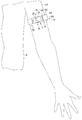
- the operation of the bio-mounted device 10 will be described by taking the case where the bio-mounted device 10 is attached to the upper left arm UA of the living body as an example.
- the user uses the other end 74 of the first band portion 62 from the inside to the outside of the ring member 110 supported by the folded portion 106 of the second band portion 64.
- the band 12 and the main body 14 form an annular shape.
- the user brings the first to third main body electrodes 30, 32, 34 and the first to fourth band electrodes 66a, 66b, 68a, 68b of the main body 14 directly into contact with the skin of the user's upper left arm UA.
- the user determines the positions of the electrodes 30, 32, 34 of the main body portion 14, the electrodes 66a, 66b of the first band portion 62, and the electrodes 68a, 68b of the second band portion 64 with respect to the upper left arm UA.
- the attachment position of the biofitting device 10 with respect to the user's upper left arm UA is such that when the user's body B is positioned in the anatomical position, the main body 14 faces the user's anterior. Is preferable.
- the minimum and maximum values of the applicable circumference of the bio-mounted device 10 to the upper left arm UA are predetermined.
- the user adjusts the length of the telescopic portion 76 of the first band portion 62 according to the outer peripheral length of the upper left arm UA, and adjusts the position of the folded portion 76a with respect to the ring member 110. That is, the user adjusts the positions of the folded-back portion 76a and the end portion 74 of the first band portion 62 to initially adjust the peripheral length of the band 12 when the band 12 is attached to the upper left arm UA.
- the first band portion 62 and the ring member 110 are folded back at desired positions, and the elasticity adjusting members (connecting portions) 84 of the surface fasteners are fastened to each other.
- the position of the first band portion 62 with respect to the user's upper left arm UA is fixed.
- the biofitting device 10 is maintained in a state of being attached to the upper left arm UA of the user.
- the user fixes the first band portion 62 via the ring member 110, and the biofitting device 10 becomes an annular body, so that the second and third main body electrodes 32 and 34 are pressed against the skin (skin) of the upper left arm UA. Then, the support portions 28a and 28b are elastically deformed. Therefore, the electrodes 32 and 34 are in close contact with the skin of the upper left arm UA.
- the first main body electrode 30 is located between the second and third main body electrodes 32 and 34, and the second and third main body electrodes 32 and 34 are pressed against the skin of the upper left arm UA and adhere to the skin of the upper left arm UA. Adhere to.
- first and second band electrodes 66a and 66b provided in the flexible first band portion 62 are in close contact with the skin of the upper left arm UA and are provided in the flexible second band portion 64.
- the 3rd and 4th band electrodes 68a and 68b are brought into close contact with the skin of the upper left arm UA.
- Reference numeral L in FIG. 8 is the peripheral length between the electrode 66b of the first band portion 62 and the ring member 110.
- the length L varies depending on the thickness of the user's upper left arm UA or the attachment site. For example, when the outer diameter of the upper left arm UA of the user is relatively small and the length L is short, the electrodes 66b and 68b are close to each other in a separated state, and the electrodes 30, 32, 34, 66a, 66b, 68a and 68b allow the user to use the electrodes 30, 32, 34, 66a, 66b, 68a and 68b.
- Electrodes 30, 32, 34, 66a, 66b, 68a, 68b come into contact with the surface of the skin so as to substantially cover the upper left arm UA. At this time, the path from the electrode 66b to the electrode 68b through the ring member 110 is shorter than the path from the electrode 66b to the electrode 68b through the main body 14.
- the contact area including the electrodes 30, 32, 34, 66a, 66b, 68a, 68b is the first band portion 62 and the second band portion.
- the 64 itself can be larger than the contact area in contact with the user's upper left arm UA.
- the electrodes 66b and 68b are separated from each other. At this time, the path from the electrode 66b to the electrode 68b through the main body 14 may be shorter than the path from the electrode 66b to the electrode 68b through the ring member 110.
- the user appropriately operates the operation unit 24 with the bio-mounted device 10 properly attached to the user's upper left arm UA.
- the control unit 42 starts communication with the external device by the communication unit 48.
- the main body 14 is set to the potential of the skin surface of the upper arm UA by the control unit 42 by the first to third main body electrodes 30, 32, 34, and by the first to fourth band electrodes 66a, 66b, 68a, 68b.
- the corresponding signal (electrocardiographic signal) is detected.
- the first to third main body electrodes 30, 32, 34 and the first to fourth band electrodes 66a, 66b, 68a, 68b output a signal corresponding to the potential to the electrocardiogram information generation unit 44.
- the electrocardiogram information generation unit 44 uses one selected from the first to third main body electrodes 30, 32, 34 and the first to fourth band electrodes 66a, 66b, 68a, 68b as a reference electrode, and uses this reference electrode as a reference electrode.
- the potential difference between the detected potential of the above and the detected potentials of the remaining plurality of electrodes is calculated, and information on the electrocardiographic signal is generated based on the negative maximum value and the positive maximum value of the calculated results.
- the electrocardiogram information generation unit 44 obtains information on the electrocardiographic signal based on the detection potential of the selected electrode.
- the electrocardiogram information generation unit 44 can obtain information not only from one electrode pair (paired electrodes) but also from a plurality of electrode pairs.
- the electrocardiogram information generation unit 44 generates an electrocardiographic signal by using a stronger signal among the signals obtained from the plurality of electrode pairs.
- the electrocardiogram generation unit 46 generates an electrocardiogram waveform based on the information obtained by the electrocardiogram information generation unit 44.
- the heartbeat information generation unit 56 obtains heartbeat information based on the detection state of the light projected from the light projecting unit 52 to the upper left arm UA and the reflected light from the upper left arm UA.
- the main body 14 of the biofitting device 10 measures the user's electrocardiographic signal and heartbeat, and obtains information on each.
- the user can easily recognize the state of his / her heart by looking at the display screen of the PC, smartphone, tablet terminal, etc. connected by the communication unit 48.
- the electrocardiographic signal measurement and the heart rate measurement be performed over several hours until an appropriate time elapses.
- An example of measuring an electrocardiographic signal and measuring a heart rate for several hours is, for example, during active hours or during sleep.
- the size (perimeter) of the outer circumference of the upper left arm UA may change according to the movement of the left arm.
- the circumference becomes relatively small, and when the arm is bent, the circumference becomes larger than when the arm is extended.
- the band 12 with electrodes has a first elastic portion 112, a second elastic portion 114 having a larger elasticity than the first elastic portion 112, and a first elastic portion 112 and a second elastic portion. It has a folded-back portion 106 between and 114.
- the second band portion 64 has a second stretchable region in a continuous region from the boundary 113a between the first stretchable portion 112 and the folded portion 106 to the fixed portion 108.
- the second stretchable portion 114 expands and contracts in the longitudinal direction (circumferential direction) according to the movement of the upper left arm (living body) UA at the position where the band 12 is attached, and has a second stretchable portion continuous with the second stretchable portion 114.
- the folded portion 106 expands and contracts in the longitudinal direction.
- the relative positions of the folded-back portion 106 and the ring member 110 change according to the expansion and contraction of the second stretchable portion 114 and the folded-back portion 106 in the longitudinal direction. Therefore, the peripheral length of the band 12 is adjusted by the second band portion 64.
- the boundary 113a between the first stretchable portion 112 having low elasticity or non-stretchability of the second band portion 64 and the folded-back portion 106 having appropriate elasticity is on the side in close contact with the upper left arm UA of the user.
- the region is continuously formed as a region having second elasticity.
- the fixing portion 108 is located proximal to the main body portion 14 with respect to the folded portion 106 along the longitudinal direction. Therefore, the length of the second telescopic portion 114 along the longitudinal direction can be made relatively long. Therefore, the second band portion 64 can have a relatively large expansion / contraction region along the longitudinal direction.
- the folded-back portion 106 and the second telescopic portion 114 expand and contract along the longitudinal direction of the band 12 according to the movement of the left arm.
- the elasticity of the folded portion 106 of the second band portion 64 along the longitudinal direction (circumferential direction) makes it easier for the band 12 to follow the movement of the upper left arm UA. Therefore, it is possible to suppress causing discomfort to the user when the bio-mounted device 10 is attached to the upper left arm UA of the user.
- the electrodes 66a and 66b are provided at a portion having the first elasticity. That is, in the first band portion 62, the electrodes 66a and 66b are provided in the first band portion 62 having less elasticity or non-stretchability than the second expansion / contraction portion 114 of the second band portion 64. ..
- the electrodes 68a and 68b are provided on the first stretchable portion 112 which is adjacent to the main body portion 14 and has the first stretchability. That is, in the second band portion 64, the electrodes 68a and 68b are provided on the first stretchable portion 112 having less stretchability or non-stretchability than the second stretchable portion 114 of the second band portion 64.
- the biofitting device 10 maintains the positional relationship between the upper left arm UA and the electrodes 66a, 66b, 68a, 68b in a fixed state.
- the body 14 faces the user's anterior when the user is in the anatomical position after the user has appropriately moved his left arm.
- the electrodes 30, 32, 34, 66a, 66b, 68a, 68b are maintained in contact with the user's upper left arm UA. Therefore, the biological device 10 can detect a stable electrocardiographic signal using the electrodes 66a, 66b, 68a, 68b, and detect a heartbeat signal using the light emitting unit 52 and the light receiving unit 54.
- the portion of the first band portion 62 in which the wirings 67a and 67b connecting the electrodes 66a and 66b and the control portion 42 are housed is made of a material having low elasticity or non-stretchability.
- the portion in which the wirings 69a and 69b connecting the electrodes 68a and 68b and the control portion 42 are housed is made of a material having low elasticity or non-stretchability. Therefore, even if the user appropriately moves the left arm, it is difficult to apply a force to extend the wirings 67a, 67b, 69a, 69b so as to extend the wirings 67a, 67b, 69a, 69b.
- the control unit 42 automatically ends the detection of the information related to the electrocardiographic signal and the heartbeat information after obtaining the electrocardiogram information and the heartbeat information for a preset time, for example.
- the control unit 42 automatically turns off the power of the main body unit 14 after finishing the detection of the information related to the electrocardiographic signal and the heartbeat information. After that, the user releases the fixation of the first band portion 62 of the bio-mounted device 10, and removes the bio-mounted device 10 from the upper left arm UA.
- the bio-mounted device 10 is maintained without being removed while the circumference changes according to the movement of the left arm from the start to the end of the detection of the information related to the electrocardiographic signal and the heartbeat information.
- the state in which the electrodes 30, 32, 34, 66a, 66b, 68a, 68b are in contact with the skin of the upper left arm UA is maintained.
- the bio-mounted device 10 can stably detect the information related to the electrocardiographic signal and the heartbeat information from the start to the end of the user's electrocardiogram and heartbeat test. ..
- the bio-mounted device 10 is used in this way.
- the biological device 10 is used not only for a relatively long measurement of several hours such as during sleep or activity, but also for a relatively short time such as within one minute or several minutes. It can also be used for measurement of. Therefore, the band 12 can also be used when the main body portion 14 is maintained in a state of being attached to the living body for a relatively short time within a few minutes, for example.
- the biofitting device 10 is attached to the upper left arm UA of the user has been described.
- the bio-mounted device 10 may be worn, for example, on the user's wrist or lower limb.
- the lower limbs include the thighs, lower legs, ankles, and the like.
- the bio-mounted device 10 can use the band 12 for the bio-mounted device 10 that is attached to a limb to obtain biometric information, such as myoelectric information, in addition to information related to electrocardiographic signals.
- biometric information such as myoelectric information
- a pulse wave sensor may be used instead of the electrode 30, or the light emitting unit 52 and the light receiving unit 54.
- the biofitting device 10 calculates the pulse wave velocity (PTT) from the time difference between the R wave peak time of the information related to the electrocardiographic signal and the rising point of the pulse wave information using the pulse wave sensor, and estimates the blood pressure. do.
- PTT pulse wave velocity
- the biomedical device 10 is preferably attached not only to detect a biological signal but also to a living body for treating the living body. That is, the band 12 can be used to maintain the state in which the main body portion 14 having a function of treating the living body is attached to the living body.
- the user can attach the biofitting device 10 to the chest, abdomen, and the abdomen. Alternatively, it may be attached to the waist.
- the stretchable portion 76 of the first band portion 62 may have higher stretchability than when it has low stretchability or non-stretchability. At this time, the elasticity of the expansion / contraction portion 76 of the first band portion 62 is lower than the elasticity of the second expansion / contraction portion 114 of the second band portion 64 along the longitudinal direction. Similarly, the first stretchability of the first stretchable portion 112 of the second band portion 64 is lower than the second stretchability of the second stretchable portion 114. Therefore, the first stretchability may not be limited to non-stretchability or non-stretchability.
- a band 12 with electrodes and a biofitting device 10 capable of suppressing causing discomfort to the user in a state of being mounted at an appropriate position. can.
- the structure of the second telescopic portion 114 of the second band portion 64 can be applied between the electrode 66b of the first band portion 62 and the ring member 110.
- the second embodiment will be described with reference to FIGS. 10 to 13.
- the second embodiment is a modification of the first embodiment, and the same members as those described in the first embodiment or members having the same functions are designated by the same reference numerals as much as possible, and detailed description thereof will be omitted.
- the fixing portion (joining portion) 108 has a first fixing member (joining portion) 108a and a second fixing member (joining portion) 108b.
- the first fixing member 108a is fixed to the outer second surface 112b of the first telescopic portion 112 between one end 102 of the band main body 100 of the second band portion 64 and the folded portion 106.
- the second fixing member 108b is fixed to the second surface 114b of the second telescopic portion 114 at the other end 104 of the second band portion 64.
- the first fixing member 108a is, for example, a hook surface or a loop surface of a hook-and-loop fastener.
- the second fixing member 108b is a loop surface of the hook-and-loop fastener, assuming that the first fixing member 108a is the hook surface of the hook-and-loop fastener.
- the second fixing member 108b is the hook surface of the hook-and-loop fastener, assuming that the first fixing member 108a is the loop surface of the hook-and-loop fastener. It is also preferable that the hook and loop fasteners of the first fixing member 108a and the second fixing member 108b are mixed on the same surface. Therefore, the user can attach / detach the first fixing member 108a and the second fixing member 108b.
- the fixed positions (fixed state) of the first fixing member 108a and the second fixing member 108b can be adjusted within the range of the lengths of the first fixing member 108a and the second fixing member 108b in the longitudinal direction.
- the position of the folded-back portion 106 of the band body 100 is adjusted. Therefore, the length of the second band portion 64 can also be adjusted, although it is a small amount as compared with the length adjustment of the first band portion 62.
- the first fixing member 108a and the second fixing member 108b of the second band portion 64 are fixed at temporary positions. As described, the first band portion 62 is fixed. After that, if necessary, the user re-fixes the first fixing member 108a and the second fixing member 108b of the second band portion 64 to a more comfortable state when the left arm is moved.
- the positions of the folded-back portion 106 and the ring member 110 at positions most distal to the second direction D2 of the second band portion 64 with respect to one end 102 of the second band portion 64 are the first fixing member 108a and the second fixing member 108b. It fluctuates depending on the relationship with. Therefore, although it is slightly smaller than the length adjustment range of the first band portion 62, when the biowear device 10 is attached to the user, the circumference length of the biowear device 10 is adjusted by the second band portion 64. Can be done. Since the folded-back portion 106 has higher elasticity than the first stretchable portion 112 which is hardly stretchable or non-stretchable, the folded-back portion 106 expands and contracts accordingly when the left arm is bent and stretched. At this time, since the length of the second band portion 64 in the longitudinal direction can be adjusted, as compared with the case described in the first embodiment, while maintaining a suitable mounting state of the bio-mounted device 10 for the user. It is possible to suppress causing discomfort to the user.
- a band 12 with electrodes and a biofitting device 10 capable of suppressing causing discomfort to the user in a state of being attached at an appropriate position.
- the third embodiment will be described with reference to FIG.
- the third embodiment is a modification of the first embodiment and the second embodiment.
- Members having the same or having the same functions as the members described in the first embodiment and the second embodiment are designated by the same reference numerals as much as possible, and detailed description thereof will be omitted.
- the folded-back portion 106 of the present embodiment has the same configuration as the first telescopic portion 112. Therefore, the folded-back portion 106 according to the present embodiment has the first elasticity.
- the bio-mounted device 10 attached to the user's upper left arm UA
- the circumference of the left arm becomes relatively small
- the circumference of the left arm becomes larger than when the arm is extended.
- the second telescopic portion 114 of the path between the folded portion 106 and the fixed portion 108 extends in the longitudinal direction.
- the path length of the band body 100 between one end 102 and the other end 104 of the second band portion 64 is extended. Therefore, the relative positional relationship of the ring member 110 with respect to the folded-back portion 106 is deviated, and the distance between one end 102 of the second band portion 64 and the folded-back portion 106 is extended.
- the folded-back portion 106 may have the first elasticity.
- the fourth embodiment will be described with reference to FIG.
- the fourth embodiment is a modification of the first to third embodiments.
- Members having the same or having the same functions as the members described in the first to third embodiments are designated by the same reference numerals as much as possible, and detailed description thereof will be omitted.
- the first band portion 62 and the second band portion 64 of the band 12 of the biofitting device 10 are continuous.
- the main body 14 is removable from the band 12.
- the base material 82 of the first band portion 62 and the base material 122 of the second band portion 64 are formed as, for example, one base material (base) 142.
- the base material 142 has a first end 144 corresponding to the other end 74 of the first band 62 and a second end 146 corresponding to the other 104 of the second band 64.
- the fixing portion 108 of the second band portion 64 of the fourth embodiment may have a structure having the first fixing member 108a and the second fixing member 108b described in the second embodiment.
- the main body can be attached to and detached from the position indicated by the broken line indicated by the reference numeral 14 of the band 12.
- the main body 14 one having an appropriate inspection function as described in the first embodiment, one having an appropriate treatment function, or one having a combination of the inspection function and the treatment function can be used.
- general devices that are not medical devices can be used for the main body 14.
- the band 12 with electrodes capable of suppressing causing discomfort to the user in a state of being attached at an appropriate position is provided. Can be provided.
- the band 12 with electrodes preferably has a structure in which wirings 67a, 67b, 69a, 69b and electrodes 66a, 66b, 68a, 68b can be removed.
- the band 12 can be cleaned, disinfected, or the like with the wirings 67a, 67b, 69a, 69b and the electrodes 66a, 66b, 68a, 68b removed from the band 12.
- the bio-mounted device 10 may be configured such that the first band portion 62 and the second band portion 64 are integrated, and the main body portion 14 cannot be easily removed from the band 12.
- the bio-attached device 10 and the bio-attached device 10 capable of suppressing causing discomfort to the user in a state of being mounted at an appropriate position.
- a band 12 with electrodes can be provided.
- the band 12 with electrodes and the bio-mounted device capable of suppressing causing discomfort to the user in a state of being mounted at an appropriate position. 10 can be provided.
- the present invention is not limited to the above embodiment, and can be variously modified at the implementation stage without departing from the gist thereof.
- Each embodiment may be carried out in combination as appropriate, in which case the combined effect can be obtained.
- the above-described embodiment includes various inventions, and various inventions can be extracted by a combination selected from a plurality of disclosed constituent requirements. For example, even if some constituent requirements are deleted from all the constituent requirements shown in the embodiment, if the problem can be solved and the effect is obtained, the configuration in which the constituent requirements are deleted can be extracted as an invention.
Landscapes
- Health & Medical Sciences (AREA)
- Life Sciences & Earth Sciences (AREA)
- Medical Informatics (AREA)
- Animal Behavior & Ethology (AREA)
- Pathology (AREA)
- Engineering & Computer Science (AREA)
- Biomedical Technology (AREA)
- Heart & Thoracic Surgery (AREA)
- Physics & Mathematics (AREA)
- Molecular Biology (AREA)
- Surgery (AREA)
- Biophysics (AREA)
- General Health & Medical Sciences (AREA)
- Public Health (AREA)
- Veterinary Medicine (AREA)
- Cardiology (AREA)
- Measurement And Recording Of Electrical Phenomena And Electrical Characteristics Of The Living Body (AREA)
- Measuring Pulse, Heart Rate, Blood Pressure Or Blood Flow (AREA)
- Electrotherapy Devices (AREA)
Priority Applications (3)
| Application Number | Priority Date | Filing Date | Title |
|---|---|---|---|
| CN202180013160.8A CN115052526B (zh) | 2020-03-10 | 2021-02-04 | 带电极的绑带和生物体装接设备 |
| DE112021000660.6T DE112021000660T5 (de) | 2020-03-10 | 2021-02-04 | Elektrodenbestücktes band und tragbare vorrichtung |
| US17/929,523 US20220409135A1 (en) | 2020-03-10 | 2022-09-02 | Electrode-equipped band and wearable apparatus |
Applications Claiming Priority (2)
| Application Number | Priority Date | Filing Date | Title |
|---|---|---|---|
| JP2020040669A JP7472555B2 (ja) | 2020-03-10 | 2020-03-10 | 電極付きバンド、及び、生体装着機器 |
| JP2020-040669 | 2020-03-10 |
Related Child Applications (1)
| Application Number | Title | Priority Date | Filing Date |
|---|---|---|---|
| US17/929,523 Continuation US20220409135A1 (en) | 2020-03-10 | 2022-09-02 | Electrode-equipped band and wearable apparatus |
Publications (1)
| Publication Number | Publication Date |
|---|---|
| WO2021181964A1 true WO2021181964A1 (ja) | 2021-09-16 |
Family
ID=77671382
Family Applications (1)
| Application Number | Title | Priority Date | Filing Date |
|---|---|---|---|
| PCT/JP2021/004150 Ceased WO2021181964A1 (ja) | 2020-03-10 | 2021-02-04 | 電極付きバンド、及び、生体装着機器 |
Country Status (5)
| Country | Link |
|---|---|
| US (1) | US20220409135A1 (enExample) |
| JP (1) | JP7472555B2 (enExample) |
| CN (1) | CN115052526B (enExample) |
| DE (1) | DE112021000660T5 (enExample) |
| WO (1) | WO2021181964A1 (enExample) |
Families Citing this family (1)
| Publication number | Priority date | Publication date | Assignee | Title |
|---|---|---|---|---|
| CN115736928A (zh) * | 2022-11-14 | 2023-03-07 | 歌尔科技有限公司 | 穿戴设备 |
Citations (6)
| Publication number | Priority date | Publication date | Assignee | Title |
|---|---|---|---|---|
| JP2008054795A (ja) * | 2006-08-30 | 2008-03-13 | Seiko Instruments Inc | 心拍情報取得装置 |
| JP2013085575A (ja) * | 2011-10-13 | 2013-05-13 | Seiko Instruments Inc | 生体情報検出装置 |
| JP2013085574A (ja) * | 2011-10-13 | 2013-05-13 | Seiko Instruments Inc | 生体情報検出装置 |
| JP2014018357A (ja) * | 2012-07-17 | 2014-02-03 | Omron Healthcare Co Ltd | 生体情報測定装置 |
| JP2014073146A (ja) * | 2012-10-02 | 2014-04-24 | Seiko Instruments Inc | 生体情報検出装置、及び固定構造 |
| JP2014128550A (ja) * | 2012-11-28 | 2014-07-10 | Seiko Instruments Inc | 生体情報検出装置 |
Family Cites Families (3)
| Publication number | Priority date | Publication date | Assignee | Title |
|---|---|---|---|---|
| US9504410B2 (en) * | 2005-09-21 | 2016-11-29 | Adidas Ag | Band-like garment for physiological monitoring |
| JP2008168054A (ja) * | 2007-01-15 | 2008-07-24 | Citizen Holdings Co Ltd | 手首装着型の生体測定装置用のバンド |
| WO2010033109A1 (en) * | 2008-09-16 | 2010-03-25 | Venetec International, Inc. | Securement system for an endotracheal tube |
-
2020
- 2020-03-10 JP JP2020040669A patent/JP7472555B2/ja active Active
-
2021
- 2021-02-04 DE DE112021000660.6T patent/DE112021000660T5/de active Pending
- 2021-02-04 CN CN202180013160.8A patent/CN115052526B/zh active Active
- 2021-02-04 WO PCT/JP2021/004150 patent/WO2021181964A1/ja not_active Ceased
-
2022
- 2022-09-02 US US17/929,523 patent/US20220409135A1/en active Pending
Patent Citations (6)
| Publication number | Priority date | Publication date | Assignee | Title |
|---|---|---|---|---|
| JP2008054795A (ja) * | 2006-08-30 | 2008-03-13 | Seiko Instruments Inc | 心拍情報取得装置 |
| JP2013085575A (ja) * | 2011-10-13 | 2013-05-13 | Seiko Instruments Inc | 生体情報検出装置 |
| JP2013085574A (ja) * | 2011-10-13 | 2013-05-13 | Seiko Instruments Inc | 生体情報検出装置 |
| JP2014018357A (ja) * | 2012-07-17 | 2014-02-03 | Omron Healthcare Co Ltd | 生体情報測定装置 |
| JP2014073146A (ja) * | 2012-10-02 | 2014-04-24 | Seiko Instruments Inc | 生体情報検出装置、及び固定構造 |
| JP2014128550A (ja) * | 2012-11-28 | 2014-07-10 | Seiko Instruments Inc | 生体情報検出装置 |
Also Published As
| Publication number | Publication date |
|---|---|
| CN115052526B (zh) | 2025-06-17 |
| US20220409135A1 (en) | 2022-12-29 |
| JP7472555B2 (ja) | 2024-04-23 |
| CN115052526A (zh) | 2022-09-13 |
| DE112021000660T5 (de) | 2022-11-24 |
| JP2021141955A (ja) | 2021-09-24 |
Similar Documents
| Publication | Publication Date | Title |
|---|---|---|
| US11724106B2 (en) | Systems and apparatus for gait modulation and methods of use | |
| KR101226169B1 (ko) | 생체신호계측 장착구 및 장착식 동작보조장치 | |
| EP2806792B1 (en) | Belt for electro impedance measurement and method using such belt | |
| JP7107531B2 (ja) | 血圧算出方法及び装置 | |
| JPH07289528A (ja) | 心電計の電極位置極め装置 | |
| US20230012971A1 (en) | Electrocardiographic measurement apparatus | |
| CN114786570B (zh) | 生理学参数感测系统和方法 | |
| WO2020013006A1 (ja) | 脈波伝播時間測定装置及び血圧測定装置 | |
| JP2004313555A (ja) | 機能的電気刺激歩行補助装置 | |
| WO2021181964A1 (ja) | 電極付きバンド、及び、生体装着機器 | |
| US12147599B2 (en) | Ultrasonic user interface device | |
| JP2019041812A (ja) | 装着型血流状態測定システムおよび装着型血流状態測定方法 | |
| JP2019051128A (ja) | 電極ユニット、脈波測定ユニット、および脈波測定装置 | |
| JP6363467B2 (ja) | 生体電位計測装置 | |
| JP6445303B2 (ja) | 生体電位計測装置 | |
| WO2019073764A1 (ja) | 生体情報測定装置、血圧測定装置、機器、生体情報測定方法、および血圧測定方法 | |
| JP2008228995A (ja) | 体脂肪測定装置 | |
| CN120051241A (zh) | 用于将传感器贴片定位在用户上的系统和方法 | |
| CN119302684A (zh) | 假性动脉瘤治疗仪 |
Legal Events
| Date | Code | Title | Description |
|---|---|---|---|
| 121 | Ep: the epo has been informed by wipo that ep was designated in this application |
Ref document number: 21767668 Country of ref document: EP Kind code of ref document: A1 |
|
| 122 | Ep: pct application non-entry in european phase |
Ref document number: 21767668 Country of ref document: EP Kind code of ref document: A1 |
|
| WWG | Wipo information: grant in national office |
Ref document number: 202180013160.8 Country of ref document: CN |