WO2021181945A1 - ターゲット設置装置 - Google Patents
ターゲット設置装置 Download PDFInfo
- Publication number
- WO2021181945A1 WO2021181945A1 PCT/JP2021/003699 JP2021003699W WO2021181945A1 WO 2021181945 A1 WO2021181945 A1 WO 2021181945A1 JP 2021003699 W JP2021003699 W JP 2021003699W WO 2021181945 A1 WO2021181945 A1 WO 2021181945A1
- Authority
- WO
- WIPO (PCT)
- Prior art keywords
- vehicle
- target
- installation device
- rod
- target installation
- Prior art date
- Legal status (The legal status is an assumption and is not a legal conclusion. Google has not performed a legal analysis and makes no representation as to the accuracy of the status listed.)
- Ceased
Links
Images





Classifications
-
- G—PHYSICS
- G01—MEASURING; TESTING
- G01M—TESTING STATIC OR DYNAMIC BALANCE OF MACHINES OR STRUCTURES; TESTING OF STRUCTURES OR APPARATUS, NOT OTHERWISE PROVIDED FOR
- G01M11/00—Testing of optical apparatus; Testing structures by optical methods not otherwise provided for
- G01M11/02—Testing optical properties
- G01M11/06—Testing the alignment of vehicle headlight devices
- G01M11/067—Details of the vehicle positioning system, e.g. by using a laser
-
- B—PERFORMING OPERATIONS; TRANSPORTING
- B62—LAND VEHICLES FOR TRAVELLING OTHERWISE THAN ON RAILS
- B62D—MOTOR VEHICLES; TRAILERS
- B62D65/00—Designing, manufacturing, e.g. assembling, facilitating disassembly, or structurally modifying motor vehicles or trailers, not otherwise provided for
- B62D65/02—Joining sub-units or components to, or positioning sub-units or components with respect to, body shell or other sub-units or components
- B62D65/16—Joining sub-units or components to, or positioning sub-units or components with respect to, body shell or other sub-units or components the sub-units or components being exterior fittings, e.g. bumpers, lights, wipers, exhausts
-
- B—PERFORMING OPERATIONS; TRANSPORTING
- B62—LAND VEHICLES FOR TRAVELLING OTHERWISE THAN ON RAILS
- B62D—MOTOR VEHICLES; TRAILERS
- B62D5/00—Power-assisted or power-driven steering
- B62D5/06—Power-assisted or power-driven steering fluid, i.e. using a pressurised fluid for most or all the force required for steering a vehicle
- B62D5/10—Power-assisted or power-driven steering fluid, i.e. using a pressurised fluid for most or all the force required for steering a vehicle characterised by type of power unit
- B62D5/16—Expansible chamber with flexible wall
-
- G—PHYSICS
- G01—MEASURING; TESTING
- G01B—MEASURING LENGTH, THICKNESS OR SIMILAR LINEAR DIMENSIONS; MEASURING ANGLES; MEASURING AREAS; MEASURING IRREGULARITIES OF SURFACES OR CONTOURS
- G01B5/00—Measuring arrangements characterised by the use of mechanical techniques
- G01B5/14—Measuring arrangements characterised by the use of mechanical techniques for measuring distance or clearance between spaced objects or spaced apertures
Definitions
- the present invention relates to a target installation device for installing a target for aiming of equipment mounted on a vehicle.
- Patent Document 1 discloses a method of positioning a target for aiming to be installed in front of a vehicle.
- An object of the present invention is to provide a technique for improving workability when installing a target for aiming.
- a target installation device for installing a target for aiming of equipment mounted on a vehicle.
- a rod-shaped member that can be arranged so as to extend in the vehicle width direction of the vehicle in front of or behind the vehicle and is provided with a target point indicating the installation position of the target.
- a reference member formed so that reference points are located on the left and right outer sides of the vehicle in the vehicle width direction when arranged with respect to the vehicle.
- a connecting portion for connecting the rod-shaped member and the reference member is provided so that the distance from the reference point to the target point in the front-rear direction satisfies a predetermined condition.
- connection part When the reference member is arranged with respect to the vehicle, it extends parallel to the center line of the vehicle extending in the front-rear direction on each of the left and right outer sides of the vehicle to connect the rod-shaped member and the reference member.
- a set of first connecting members When the reference member is arranged with respect to the vehicle, a set of second members extending from each of the left and right outer sides of the vehicle toward the center side in the vehicle width direction and connecting the rod-shaped member and the reference member.
- a target installation device including a connecting member, is provided.
- the accompanying drawings are included in the specification and are used to form a part thereof, show embodiments of the present invention, and explain the principles of the present invention together with the description thereof.
- the plan view which shows the outline of the target installation apparatus which concerns on 1st Embodiment.
- the plan view which shows the structural example of the reference member.
- the figure which shows the outline of the reference point forming part 40L The figure explaining the structural example of the connecting member.
- the plan view which shows the outline of the target installation apparatus which concerns on 2nd Embodiment.
- the X direction indicates the front-rear direction of the vehicle V
- the Y direction indicates the vehicle width direction of the vehicle V
- the Z direction indicates the vertical direction.
- expressions such as front / rear, left / right (side), and upper / lower indicate relative positional relationships with respect to the vehicle body, and for example, expressions such as front and front are + X.
- the expressions such as rear and rear correspond to the -X direction.
- expressions such as left and left correspond to the + Y direction
- expressions such as right and right correspond to the ⁇ Y direction.
- the expressions such as the inside of the vehicle body / the outside of the vehicle body (inside and outside the vehicle body) also show the relative positional relationship with respect to the vehicle body.
- FIG. 1 is a plan view showing an outline of the target installation device 1 according to the first embodiment.
- FIG. 2 is a diagram showing a state in which the target installation device 1 and the target T of FIG. 1 are arranged with respect to the vehicle 1.
- the target installation 1 is a device for installing the target T at a predetermined position for adjusting devices such as lights and external sensor mounted on the vehicle V.
- a target T for aiming the radar V1 as an external sensor mounted on the front portion of the vehicle V is installed.
- the target installation can also be used to adjust other external sensors such as cameras and riders, and can also be used to adjust equipment behind the vehicle V by arranging it behind the vehicle V.
- the target installation device 1 includes a front bar member 2, a reference member 4, and a connecting portion 6.
- the front bar member 2 and the reference member 4 extending in the vehicle width direction are provided apart from each other in the front-rear direction, and the connecting portion 6 connects them. Then, by aligning the reference points 400L and 400R formed on the reference member 4 with the predetermined positions of the vehicle V, the target point TP formed on the front bar member 2 satisfies the predetermined conditions for adjusting the device. It is adjusted to.
- the predetermined conditions can be set as appropriate.
- the target point TP is on an extension of the center line VC of the vehicle V, and the distance in the front-rear direction from the wheel center of the front wheels is a predetermined distance of 1 to 10 m. It may be.
- the target point TP may be offset in the width direction from the center line VC of the vehicle V.
- FIG. 3 is a diagram showing a configuration example of the front bar member 2.
- the front bar member 2 is a rod-shaped member provided with a target point TP indicating an installation position of the target T. When it is arranged with respect to the vehicle V, it can be arranged so as to extend in the vehicle width direction in front of or behind the vehicle V.
- the front bar member 2 includes a main body 21, a point forming member 22 forming a target point TP, and pins 23, 24L, 24R capable of locking a connecting member (described later) of the connecting portion 6.
- the main body 21 is a member forming the skeleton of the front bar member 2, and may be formed of, for example, a metal material and may have a hollow and rectangular cross-sectional shape.
- the main body 21 is divided into left and right parts with the point forming member 22 interposed therebetween, and includes a left side portion 21L and a right side portion 21R.
- the main body 21 may be integrally molded.
- the point forming member 22 is a member that defines the position of the target point TP.
- the point forming member 22 is provided so as to be sandwiched between the left side portion 21L and the right side portion 21R of the main body 21.
- the point forming member 22 has a convex portion that can be engaged with the hollow portion of the main body 21, and may be attached by engaging with the main body 21.
- at least one of the left side portion 21L and the right side portion 21R may have a convex portion
- the point forming member 22 may have a concave portion that engages with the convex portion.
- the point forming member 22 may be provided so that the point forming member 22 sandwiches the main body 21 from above, instead of being sandwiched between the left side portion 21L and the right side portion 21R.
- the point forming member 22 since the point forming member 22 is sandwiched between the left side portion 21L and the right side portion 21R, the position of the point forming member 22 in the width direction can be accurately determined.
- the point forming member 22 includes a portion having a triangular shape with the main body 21 side as the base and the reference member 4 side as the apex, and the apex of this triangle is defined as the target point TP. Therefore, by aligning the target T with the apex of this triangle, the target T can be installed so as to satisfy a predetermined condition for adjusting the device.
- the pins 23, 24L, 24R lock the connecting members 60L, 60R, 62L, 62R of the connecting portion 6, which will be described later, to the front bar member 2. More specifically, the pin 23 locks the connecting members 62L and 62R, the pin 24L locks the connecting member 60L, and the pin 24R locks the connecting member 60R to the front bar member 2. That is, the pins 23, 24L, and 24R are mounting members for the connecting portion 6 on the front bar member 2 side. In the present embodiment, the pins 23, 24L, and 24R are provided so as to extend upward from the base portion 25 extending from the main body 21 toward the reference member side.
- the base 25 is, for example, a metal plate and can be fixed to the main body 21 by welding or the like.
- the connecting members 62L and 62R are locked by a common pin 23 on the front bar member 2 side.
- a triangle is formed by the pins 408L and 408R and the pin 24 on the reference member 4 side, and when these are connected by the connecting members 62L and 62R, the position of the pin 24 is determined at one point.
- the pin 23 is provided on an extension line of the center line VC of the vehicle V. As a result, the distances from the pin 23 to the pins 408L and 408R on the reference member 4 side are equidistant, so that the lengths of the connecting members 62L and 62R can be made common.
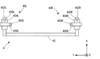
- FIG. 4 is a plan view showing a configuration example of the reference member 4.
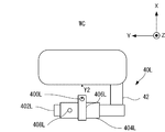
- 5A and 5B are views showing an outline of the reference point forming portion 40L, FIG. 5A is a left side view, and FIG. 5B is a plan view.
- the reference point forming portion 40R may also have a corresponding configuration.
- the reference member 4 is a member provided with reference points 400L and 400R which serve as a reference on the vehicle V side when determining the distance between the vehicle V and the target point TP.
- the reference member 4 is formed so that the reference points 400L and 400R are located on the left and right outside of the vehicle V in the vehicle width direction when the reference member 4 is arranged with respect to the vehicle V.
- the reference member 4 includes a set of reference point forming portions 40L and 40R and a positioning portion 42.
- Reference point forming portions 40L and 40R are formed with reference points 400L and 400R in the front-rear direction on the vehicle V side.
- the wheel center WCs of the left and right tires WL and WR (front wheels) of the vehicle V are the reference in the front-rear direction. Therefore, the operator arranges the reference point forming portions 40L and 40R so that the reference points 400L and 400R coincide with the wheel center WC of the front wheels WL and WR in the front-rear direction.
- the distance in the front-rear direction from the wheel center WC of the left and right tires WL and WR (front wheels) to the target T can be set as a desired distance.
- the reference point forming portions 40L and 40R make the left and right reference points 400L and 400R equidistant from the center line VC on the line connecting the centers of the left and right tires WL and WR of the vehicle V. Adjustable to position.
- the reference point forming portion 40L has a base portion 402L, a front-rear direction moving portion 404L that can move in the front-rear direction with respect to the base portion 402L, and a vehicle width direction with respect to the front-rear direction moving portion 404L. Includes a vehicle width direction moving portion 406L that can be moved to.
- the reference point 400L since the reference point 400L is provided in the vehicle width direction moving portion 406L, the reference point 400L moves to a predetermined position on the XY plane by the movement of the front-rear direction moving portion 404L and the vehicle width direction moving portion 406L. It is possible.
- the deviation of the reference point 400L from the wheel center WC can be adjusted.
- a scale is provided on the vehicle width direction moving portion 406L, and by matching the readings of the scales provided on the left and right vehicle width direction moving portions 406L and 406R, the vehicle V and the vehicle of the reference member 4 are provided. The center in the width direction can be aligned.
- a common pin 408L for locking the connecting members 60L and 62L is provided on the front-rear moving portion 404L. Therefore, even if the front-rear direction moving portion 404L moves in the front-rear direction, the distance between the pin 408L and the reference point 400L in the front-rear direction is kept constant, so that the distance in the front-rear direction from the reference point 400L to the target point TP also increases. It is kept constant.
- the front-rear direction moving portion 404L moves in the front-rear direction by sliding with respect to the base portion 402L, and the vehicle width direction moving portion 406L slides with respect to the front-rear direction moving portion 404L to move the vehicle width. Move in the direction.
- the reference point forming portions 40L and 40R are not limited to the above configuration, and the positions of the reference points 400L and 400R can be adjusted by a well-known method.
- the reference point forming portions 40L and 40R may be provided with a regulation mechanism for restricting the movement of the reference point forming portions 40L and 40R after the position adjustment by the front-rear direction moving portions 404L and 404R and the vehicle width direction moving portions 406L and 406R. As a result, it is possible to prevent the reference point from shifting after the adjustment.
- the positioning portion 42 is a rod-shaped member provided so as to connect the left and right reference point forming portions 40L and 40R.
- the positioning portion 42 may be a metal pipe, and is connected to the base portions 402L and 402R at the end portion thereof.
- the positioning unit 42 abuts on the tires WL and WR of the vehicle V from the side opposite to the side where the front bar member 2 is located in the front-rear direction, so that the positioning unit 42 refers to the vehicle V.
- Positioning of the point forming portions 40L and 40R is performed. Specifically, first, the positioning portion 42 abuts on the tires WL and WR to regulate the movement of the base portions 402L and 402R in the front-rear direction, particularly forward movement. Therefore, by determining the positions of the reference points 400L and 400R by the front-back moving portions 404L and 404R in that state, the reference point can be positioned more accurately.
- the adjustment by the front-rear moving parts 404L and 404R after positioning by the positioning part 42 is, for example, to hang a weight from the wheel center of the tire WL so that the position indicated by the weight and the reference points 400L and 400R match in the front-rear direction. May be done by. Further, the adjustment by the vehicle width direction moving portions 406L and 406R may be performed by matching the distance Y2 of the reference points 400L and 400R from the wheels WL and WR to the left and right by using a scale or the like.
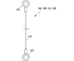
- FIG. 6 is a diagram illustrating a configuration example of the connecting members 60L, 60R, 62L, 62R.
- the configuration of the connecting members 60L, 60R, 62L, 62R may be taken as an example of the connecting member 60L, but the connecting members 60R, 62L, 62R may also have the same configuration.
- the connecting portion 6 connects the front bar member 2 and the reference member 4 so that the distance in the front-rear direction from the reference points 400L and 400R to the target point TP satisfies a predetermined condition.
- the connecting portion 6 has a set of connecting members 60L and 60R and a set of connecting members 62L and 62R for connecting the front bar member 2 and the reference member 4, respectively.
- the connecting member 60L includes a wire 600 and a fixing portion 602.
- the wire 600 is set to a length such that the distance from the reference point 400L to the target point TP in the front-rear direction satisfies a predetermined condition.
- the fixing portion 602 fixes the wire 600 to the front bar member 2 or the reference member 4.
- the fixing portion 602 has a ring shape that can be locked with the pin 24L.
- the fixing portion 602 is formed of an elastic member such as resin or rubber. Further, the fixing portion 602L may be detachable from the wire 600L, or may be fixed with solder or solder.
- the connecting members 60L and 60R are parallel to the center line VC of the vehicle V extending in the front-rear direction on each of the left and right outer sides of the vehicle V when the reference member 4 is arranged with respect to the vehicle V. It extends to connect the front bar member 2 and the reference member 4. Further, when the reference member 4 is arranged with respect to the vehicle V, the connecting members 62L and 62R extend from each of the left and right outer sides of the vehicle V toward the center side in the vehicle width direction, and the front bar member 2 and the reference member 4 And connect.
- the connecting members 60L and 60R need only extend in the front-rear direction on the left and right outer sides of the vehicle V to connect the front bar member 2 and the reference member 4, and are not parallel to the center line VC of the vehicle V. Can also be adopted.
- the target installation device 1 is for installing the target T so that the distance X1 between the reference positions 400L and 400R on the vehicle V side and the target T in the front-rear direction satisfies a predetermined condition.
- X3 is the distance in the front-rear direction from the target point TP to the pins 24L and 24R
- X4 is the distance from the reference points 400L and 400R to the pins 408L and 408R.
- the connecting members 60L and 60R can adopt a configuration that is not parallel to the center line VC of the vehicle V, but by being provided parallel to the center line VC, the reference point 400L is based on the equation (1). , 400R and the length can be easily set according to the distance between the target point TP.
- the length L1 of the connecting members 62L and 62R is based on the length X2 of the connecting members 60L and 60R and the distance Y3 in the Y direction from the center line VC of the vehicle V to the pins 408L and 408R.
- L1 (X2 2 + Y3 2 ) 1/2 formula (2) Can be calculated with.
- the target point TP can also be specified by connecting the front bar member 2 and the reference member 4 with the connecting members 62L and 62R without using the connecting members 60L and 60R.
- the connecting members 60L and 60R are not used, the front bar member 2 may rotate around the pin 23.
- the position of the target point TP provided offset in the X direction with respect to the pin 23 may shift, and the target T may not be arranged with a desired accuracy.
- the target point TP is at a position offset from the center line VC of the vehicle V in the vehicle width direction (Y direction), the influence of the deviation of the target point TP due to the rotation of the front bar member 2 becomes large. It ends up.
- the front bar member 2 uses the pin 23 as the rotation axis. It is possible to suppress the rotation. Specifically, the relative positions of the pins 24L and 24R separated from the pin 23 with respect to the reference member 4 are positioned by the connecting members 62L and 62R, so that the rotation of the front bar member 2 around the pin 23 is suppressed. NS. Therefore, since the deviation of the target point TP can be reduced, the accuracy of the position of the target point TP can be further improved.
- the required distance X1 from the reference point on the vehicle V side to the target point TP may differ depending on the type of vehicle V and the type of equipment to be adjusted.
- connecting members 60L, 60R, 62L, 62R having a plurality of lengths may be prepared, and connecting members 60L, 60R, 62L, 62R corresponding to the required distance X1 may be used.
- connecting members 60L, 60R, 62L, 62R, and the front bar member 2 and the reference member 4 are common. Can be used.
- the operator inserts the reference member 4 into the lower part of the vehicle V. After that, the operator aligns the center of the reference member 4 in the width direction with the center of the vehicle V in the width direction by using scales or the like provided on the vehicle width direction moving portions 406L and 406R.
- the operator connects the reference member 4 and the front bar member 2 with the connecting members 60L and 60R. After that, the operator positions the reference member 4 by lightly pulling the front bar member 2 in the front direction of the vehicle V and bringing the positioning portion 42 into contact with the tires WL and WR.
- the operator adjusts the position of the reference point on the vehicle V side by the front-rear direction moving portions 404L and 404R.
- the operator connects the connecting members 62L and 62R to the reference member 4 and the front bar member 2, pulls the front bar member 2 in the front direction of the vehicle V, and places the front bar member 2 on the ground when it is stable. Mark the position corresponding to the target point TP.
- the front is provided by the connecting members 60L and 60R extending on the left and right outside of the vehicle V and the connecting members 62L and 62R extending from the left and right outside of the vehicle V to the center side of the vehicle V.
- the bar member 2 and the reference member 4 are connected.
- the front bar member 2 and the reference member 4 are connected by the connecting portion 6 so that the distance in the front-rear direction from the reference point on the vehicle V side to the target point TP satisfies a predetermined condition. Therefore, since it is not necessary to measure the distance between the front bar member 2 and the reference member 4 in the front-rear direction, the working time can be shortened.
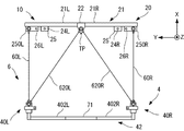
- FIG. 7A and 7B are plan views showing an outline of the target installation device 10 according to the second embodiment.
- the same components as those in the first embodiment are designated by the same reference numerals and the description thereof will be omitted.
- the target installation device 1 according to the first embodiment can be used for a vehicle V having a vehicle width within a predetermined range by adjusting with the vehicle width direction moving units 406L and 406R. However, since the distance between the reference point forming portions 40L and 40R is fixed, the target installation device 1 may not be used when the vehicle width of the vehicle V is larger than this distance.
- the target installation device 1 according to the second embodiment can also handle a vehicle V having a wider range of vehicle widths.
- the front bar member 20 When the front bar member 20 is arranged with respect to the vehicle V, the front bar member 20 can be connected to the connecting members 60L and 60R at a plurality of positions where the distance from the center line VC differs in the vehicle width direction on each of the left and right sides of the vehicle V. be.
- the front bar member 20 has a plurality of pins 24L, 24R, pins 26L, 26R and 27L, 27R having different distances from the center line VC on each of the left and right sides.
- the pins 26L and 27L are provided on the base portion 250L outside the base portion 25.
- the pins 26R and 27R are provided on the base portion 250R outside the base portion 25.
- the connecting members 60L and 60R can be connected to the front bar member 20 at positions corresponding to the vehicle width of the vehicle V.
- the positioning portion 420 is formed so as to be divisible into a left side portion 420L and a right side portion 420R, and can hold the extension members 70 and 71 according to the size of the vehicle V to be aimed in the vehicle width direction.
- the stretching members 70 and 71 may be formed so as to fit inside the pipe.
- the distance between the pins 408L and 408R when the positioning member 420 sandwiches the extension member 70 corresponds to the distance between the pins 26L and 26R, and between the pins 408L and 408R when the extension member 71 is sandwiched.
- the distance between pins 27L and 27R corresponds to the distance between pins 27L and 27R.
- the distance between the pins 408L and 408R when the positioning member 420 sandwiches the extension member 70 is equal to the distance between the pins 26L and 26R, and the distance between the pins 408L and 408R when the extension member 71 is sandwiched. Is equal to the distance between pins 27L and 27R.
- the front bar member 20 and the reference member 400 can be connected by the connecting members 60L and 60R in three steps of width including the case where the extending members 70 and 71 are not used.
- connecting members 62L and 62R may be prepared according to the distance between the connecting members 60L and 60R.
- the front bar member 20 and the reference member 400 can be connected by the connecting members 60L and 60R with a plurality of widths. Therefore, the common target installation device 10 can be used for the vehicle V having a wider range of vehicle widths.
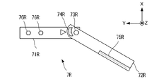
- FIG. 8A is a plan view showing a configuration example of the front bar member 200 according to the third embodiment
- FIG. 8B is a plan view showing a configuration example of the extension member 7R.
- the same components as those in the first embodiment are designated by the same reference numerals and the description thereof will be omitted.
- the target point TP is provided on the front bar member 2 .
- sensors such as radar may be arranged in front of and to the side of the vehicle V.
- the target point TP is provided at a position tilted at a predetermined angle with respect to the front bar member 2.
- extension members 7L and 7R for providing the target point TP at a position tilted at a predetermined angle with respect to the front bar member 2 are adopted.
- the other may also have a corresponding configuration.
- Extension members 7L and 7R can be attached to the front bar member 200 so as to extend at a predetermined angle with respect to the front bar member 200.
- the extension member 7R includes a mounting portion 71R, a rotating portion 72R, a rotating shaft member 73R, an angle scale 74R, and a scale 75R.
- the mounting portion 71R is a portion to be mounted on the front bar member 200.
- the mounting portion 71R can be fixed to the front bar member 200 by a fastening member 76R such as a bolt.
- the rotating portion 72 rotates with respect to the mounting portion 71R with the rotating shaft member 73R as the axis. Thereby, the target point TP can be positioned at a desired angle with respect to the front bar member 200.
- the angle memory 74R is a memory for confirming the rotation angle of the rotating portion 72. Since the designated angle of the rotating portion 72 may differ depending on the type of the vehicle V and the type of the device to be aimed, the operator reads the angle memory 74R and adjusts the rotating portion 72 to the specified angle. do.
- the scale 75R is for confirming the distance from the rotating shaft member 73R.
- a designated distance from the rotating shaft member 73R can be set according to the type of the vehicle V and the type of the device to be aimed. Therefore, the operator reads the scale 75R and sets the designated distance from the rotating shaft member 73R to the target point TP.
- the target point TP can be positioned even when the target point TP is set at a predetermined distance and a predetermined angle from the front bar member 200.
- a target installation device for example, 1) for installing a target (for example, T) for aiming a device (for example, V1) mounted on a vehicle (for example, V).
- a rod-shaped member for example, 2) that can be arranged so as to extend in the vehicle width direction of the vehicle in front of or behind the vehicle and is provided with a target point (for example, TP) indicating the installation position of the target.
- a reference member for example, 4) formed so that reference points (for example, 400L and 400R) are located on the left and right outside in the vehicle width direction of the vehicle when arranged with respect to the vehicle.
- a connecting portion (for example, 6) for connecting the rod-shaped member and the reference member is provided so that the distance from the reference point to the target point in the front-rear direction satisfies a predetermined condition.
- the connection part When the reference member is arranged with respect to the vehicle, the rod-shaped member and the reference member extend parallel to the center line (for example, VC) of the vehicle extending in the front-rear direction on each of the left and right outer sides of the vehicle.
- a set of first connecting members for example, 60L, 60R
- a set of second members extending from each of the left and right outer sides of the vehicle toward the center side in the vehicle width direction and connecting the rod-shaped member and the reference member.
- Including connecting members eg 62L, 62R),
- the front bar member 2 and the reference member 4 are connected by the first connecting member and the second connecting member extending outside the vehicle.
- the positioning accuracy of the target point TP can be further improved, and the workability when installing the target T for aiming can be improved.
- the reference points are provided on the left and right outside in the vehicle width direction, the target installation device can be used for vehicles having different vehicle widths.
- the reference member is A set of reference point forming portions (for example, 40L, 40R) on which the reference point is formed, It is provided so as to connect a set of the reference point forming portions, and when it is arranged with respect to the vehicle, the rod-shaped member comes into contact with the tire of the vehicle from the side opposite to the side where the rod-shaped member is located, whereby the said with respect to the vehicle. It has a rod-shaped positioning portion (for example, 42) for positioning the reference point forming portion.
- the reference member can be positioned more reliably in the front-rear direction.
- the reference point forming portion can adjust a set of the reference points so as to be located on a line connecting the centers of the left and right tires (for example, WL, WR) of the vehicle and at an equidistant distance from the center line. be.
- the target can be positioned more accurately when the wheel center is used as a reference point.
- the rod-shaped member When the rod-shaped member is arranged with respect to the vehicle, the rod-shaped member can be connected to the first connecting member at a plurality of positions on the left and right sides of the vehicle, each of which has a different distance from the center line in the vehicle width direction. There are (eg 24,26,27).
- the target can be installed according to the width of the vehicle.
- the positioning portion is formed so as to be divisible, and can hold an extension member (for example, 70,71) according to the size of the vehicle to be aimed in the vehicle width direction.
- the target can be installed on a vehicle having a wider range of vehicle widths.
- the first connecting member and the second connecting member include a wire.
- the distance between the rod-shaped member and the reference member can be kept constant.
- the reference member has left and right common mounting portions (for example, 408L, 408R) to which the first connecting member and the second connecting member are mounted.
- parts (pins) can be shared.
- the rod-shaped member has a common mounting portion (for example, 23) to which a set of the second connecting members is mounted on an extension of the center line of the vehicle when the reference member is arranged with respect to the vehicle.
- a triangle is formed by the mounting portion on the reference member side and the mounting portion on the rod-shaped member side. Therefore, when these are connected by the second connecting member, the position of the mounting portion on the reference member side is set to one point. Can be decided.
- An extension member (for example, 7L, 7R) extending at a predetermined angle with respect to the rod-shaped member can be attached to the rod-shaped member.
- the target point can be positioned even when the target point is set at a predetermined distance and a predetermined angle from the rod-shaped member.
- Each of the set of the first connecting members extends parallel to the center line of the vehicle extending in the front-rear direction to connect the rod-shaped member and the reference member.
- the outer portion of the front bar member and the reference point and distance on the vehicle side can be adjusted more easily.
- 1 target installation device 2 front bar member, 4 reference member, 6 connection part, 60L, 60R, 62L, 62R connection member
Landscapes
- Engineering & Computer Science (AREA)
- Physics & Mathematics (AREA)
- Chemical & Material Sciences (AREA)
- General Physics & Mathematics (AREA)
- Mechanical Engineering (AREA)
- Transportation (AREA)
- Combustion & Propulsion (AREA)
- Manufacturing & Machinery (AREA)
- Optics & Photonics (AREA)
- Analytical Chemistry (AREA)
- Radar Systems Or Details Thereof (AREA)
- Body Structure For Vehicles (AREA)
- Automobile Manufacture Line, Endless Track Vehicle, Trailer (AREA)
Abstract
Description
前記車両の前方又は後方において前記車両の車幅方向に渡って延びるように配置可能であり、前記ターゲットの設置位置を示すターゲットポイントが設けられた棒状部材と、
前記車両に対して配置された際に、前記車両の車幅方向の左右の外側に基準点がそれぞれ位置するように形成された基準部材と、
前記基準点から前記ターゲットポイントまでの前後方向の距離が所定の条件を満たすように、前記棒状部材と前記基準部材とを接続する接続部と、を備え、
前記接続部は、
前記基準部材が前記車両に対して配置された際に、前記車両の左右の外側のそれぞれにおいて、前後方向に延びる前記車両の中心線と平行に延びて前記棒状部材と前記基準部材とを接続する一組の第1接続部材と、
前記基準部材が前記車両に対して配置された際に、前記車両の左右の外側のそれぞれから前記車幅方向の中心側に延びて前記棒状部材と前記基準部材とを接続する一組の第2接続部材と、を含む、ターゲット設置装置が提供される。
<ターゲット設置装置の概要>
図1は、第一実施形態に係るターゲット設置装置1の概略を示す平面図である。図2は、車両1に対して図1のターゲット設置装置1及びターゲットTを配置した状態を示す図である。ターゲット設置1は、車両Vに搭載されるライトや外界センサ等の機器の調整のために、所定の位置にターゲットTを設置するための装置である。以下では、車両Vの前部に搭載される外界センサとしてのレーダV1のエーミング用のターゲットTを設置する場合の例について説明する。しかしながら、ターゲット設置は、カメラやライダ等の他の外界センサの調整にも使用可能であり、また、車両Vの後方に配置することで車両Vの後部の機器の調整にも使用可能である。
図3を併せて参照する。図3はフロントバー部材2の構成例を示す図である。フロントバー部材2は、ターゲットTの設置位置を示すターゲットポイントTPが設けられる棒状部材である。車両Vに対して配置する際は、車両Vの前方又は後方において車幅方向に渡って延びるように配置可能である。フロントバー部材2は、本体21と、ターゲットポイントTPを形成するポイント形成部材22と、接続部6の接続部材(後述)を係止可能なピン23,24L,24Rとを含む。
図4は、基準部材4の構成例を示す平面図である。また、図5A及び図5Bは、基準点形成部40Lの概略を示す図であって、図5Aは左側面図、図5Bは平面図である。なお、以下の説明において、基準点形成部40Lについて説明した構成に関しては、基準点形成部40Rも対応する構成を有し得る。
図1と併せて図6を参照する。図6は、接続部材60L,60R,62L,62Rの構成例を説明する図である。以下、接続部材60L,60R,62L,62Rの構成について接続部材60Lを例にする場合があるが、接続部材60R,62L,62Rも同様の構成を有し得る。
X2=X1+X3-X4 式(1)
となる。ここで、X3はターゲットポイントTPからピン24L,24Rまでの前後方向の距離、X4は基準点400L,400Rからピン408L,408Rまでの距離である。上述のように、接続部材60L,60Rは、車両Vの中心線VCと平行でない構成も採用可能であるが、中心線VCと平行に設けられることにより、式(1)に基づいて基準点400L,400R及びターゲットポイントTPの間の距離に応じた長さに容易に設定することができる。
L1=(X22+Y32)1/2 式(2)
で算出することができる。
次に、ターゲット設置装置1の使用方法の例について説明する。
以下、図7を用いて第二実施形態に係るターゲット設置装置10について説明する。図7A及び図7Bは、第二実施形態に係るターゲット設置装置10の概略を示す平面図である。なお、第一実施形態と同様の構成については同様の符号を付して説明を省略する。
以下、図8を用いて第三実施形態に係るターゲット設置装置について説明する。図8Aは第三実施形態に係るフロントバー部材200の構成例を示す平面図であり、図8Bは、延長部材7Rの構成例を示す平面図である。なお、第一実施形態と同様の構成については同様の符号を付して説明を省略する。
上記実施形態は以下のターゲット設置装置を少なくとも開示する。
前記車両の前方又は後方において前記車両の車幅方向に渡って延びるように配置可能であり、前記ターゲットの設置位置を示すターゲットポイント(例えばTP)が設けられた棒状部材(例えば2)と、
前記車両に対して配置された際に、前記車両の車幅方向の左右の外側に基準点(例えば400L,400R)がそれぞれ位置するように形成された基準部材(例えば4)と、
前記基準点から前記ターゲットポイントまでの前後方向の距離が所定の条件を満たすように、前記棒状部材と前記基準部材とを接続する接続部(例えば6)と、を備え、
前記接続部は、
前記基準部材が前記車両に対して配置された際に、前記車両の左右の外側のそれぞれにおいて、前後方向に延びる前記車両の中心線(例えばVC)と平行に延びて前記棒状部材と前記基準部材とを接続する一組の第1接続部材(例えば60L,60R)と、
前記基準部材が前記車両に対して配置された際に、前記車両の左右の外側のそれぞれから前記車幅方向の中心側に延びて前記棒状部材と前記基準部材とを接続する一組の第2接続部材(例えば62L,62R)と、を含む、
前記基準部材は、
前記基準点が形成される一組の基準点形成部(例えば40L,40R)と、
一組の前記基準点形成部を接続するように設けられ、前記車両に対して配置される際に前記棒状部材がある側と反対側から前記車両のタイヤに当接することで、前記車両に対する前記基準点形成部の位置決めを行う棒状の位置決め部(例えば42)と、を有する。
前記基準点形成部は、一組の前記基準点を、前記車両の左右のタイヤ(例えばWL,WR)の中心を結ぶ線上で、かつ、前記中心線から等距離に位置するように調整可能である。
前記棒状部材は、前記車両に対して配置された際に、前記車両の左右のそれぞれにおいて、前記車幅方向で前記中心線からの距離が異なる複数の位置で前記第1接続部材と接続可能である(例えば24,26,27)。
前記位置決め部は、分割可能に形成され、エーミングの対象となる前記車両の車幅方向の大きさに応じた延伸部材(例えば70,71)を挟持可能である。
前記第1接続部材及び前記第2接続部材はワイヤを含む。
前記基準部材は、前記第1接続部材及び前記第2接続部材が取り付けられる共通の取付部(例えば408L,408R)を左右に有する。
前記棒状部材は、前記基準部材が前記車両に対して配置された際に、前記車両の前記中心線の延長線上において一組の前記第2接続部材が取り付けられる共通の取付部(例えば23)を有する。
前記棒状部材には、前記棒状部材に対して所定の角度で延伸する延長部材(例えば7L,7R)を取付可能である。
一組の前記第1接続部材はそれぞれ、前後方向に延びる前記車両の中心線と平行に延びて前記棒状部材と前記基準部材とを接続する。
Claims (10)
- 車両に搭載される機器のエーミング用のターゲットを設置するためのターゲット設置装置であって、
前記車両の前方又は後方において前記車両の車幅方向に渡って延びるように配置可能であり、前記ターゲットの設置位置を示すターゲットポイントが設けられた棒状部材と、
前記車両に対して配置された際に、前記車両の車幅方向の左右の外側に基準点がそれぞれ位置するように形成された基準部材と、
前記基準点から前記ターゲットポイントまでの前後方向の距離が所定の条件を満たすように、前記棒状部材と前記基準部材とを接続する接続部と、を備え、
前記接続部は、
前記基準部材が前記車両に対して配置された際に、前記車両の左右の外側のそれぞれにおいて、前記棒状部材と前記基準部材とを接続する一組の第1接続部材と、
前記基準部材が前記車両に対して配置された際に、前記車両の左右の外側のそれぞれから前記車幅方向の中心側に延びて前記棒状部材と前記基準部材とを接続する一組の第2接続部材と、を含む、
ターゲット設置装置。 - 請求項1に記載のターゲット設置装置であって、
前記基準部材は、
前記基準点が形成される一組の基準点形成部と、
一組の前記基準点形成部を接続するように設けられ、前記車両に対して配置される際に前記棒状部材がある側と反対側から前記車両のタイヤに当接することで、前記車両に対する前記基準点形成部の位置決めを行う棒状の位置決め部と、を有する、
ターゲット設置装置。 - 請求項2に記載のターゲット設置装置であって、
前記基準点形成部は、一組の前記基準点を、前記車両の左右のタイヤの中心を結ぶ線上で、かつ、前記車両の前後方向に延びる中心線から等距離に位置するように調整可能である、
ターゲット設置装置。 - 請求項1ないし3のいずれか1項に記載のターゲット設置装置であって、前記棒状部材は、前記車両に対して配置された際に、前記車両の左右のそれぞれにおいて、前記車幅方向で前記車両の前後方向に延びる中心線からの距離が異なる複数の位置で前記第1接続部材と接続可能である、ターゲット設置装置。
- 請求項2に記載のターゲット設置装置であって、前記位置決め部は、分割可能に形成され、エーミングの対象となる前記車両の車幅方向の大きさに応じた延伸部材を挟持可能である、ターゲット設置装置。
- 請求項1ないし5のいずれか1項に記載のターゲット設置装置であって、前記第1接続部材及び前記第2接続部材はワイヤを含む、ターゲット設置装置。
- 請求項1ないし6のいずれか1項に記載のターゲット設置装置であって、前記基準部材は、前記第1接続部材及び前記第2接続部材が取り付けられる共通の取付部を左右に有する、ターゲット設置装置。
- 請求項1ないし7のいずれか1項に記載のターゲット設置装置であって、前記棒状部材は、前記基準部材が前記車両に対して配置された際に、前記車両の前後方向に延びる中心線の延長線上において一組の前記第2接続部材が取り付けられる共通の取付部を有する、ターゲット設置装置。
- 請求項1ないし8のいずれか1項に記載のターゲット設置装置であって、前記棒状部材には、前記棒状部材に対して所定の角度で延伸する延長部材を取付可能である、ターゲット設置装置。
- 請求項1ないし9のいずれか1項に記載のターゲット設置装置であって、一組の前記第1接続部材はそれぞれ、前記車両の前後方向に延びる中心線と平行に延びて前記棒状部材と前記基準部材とを接続する、ターゲット設置装置。
Priority Applications (3)
| Application Number | Priority Date | Filing Date | Title |
|---|---|---|---|
| BR112022016840A BR112022016840A2 (pt) | 2020-03-11 | 2021-02-02 | Aparelho de instalação de alvo |
| CN202180017485.3A CN115210134B (zh) | 2020-03-11 | 2021-02-02 | 标靶设置装置 |
| US17/939,608 US11807324B2 (en) | 2020-03-11 | 2022-09-07 | Target installation apparatus |
Applications Claiming Priority (2)
| Application Number | Priority Date | Filing Date | Title |
|---|---|---|---|
| JP2020042124A JP7284118B2 (ja) | 2020-03-11 | 2020-03-11 | ターゲット設置装置 |
| JP2020-042124 | 2020-03-11 |
Related Child Applications (1)
| Application Number | Title | Priority Date | Filing Date |
|---|---|---|---|
| US17/939,608 Continuation US11807324B2 (en) | 2020-03-11 | 2022-09-07 | Target installation apparatus |
Publications (1)
| Publication Number | Publication Date |
|---|---|
| WO2021181945A1 true WO2021181945A1 (ja) | 2021-09-16 |
Family
ID=77671357
Family Applications (1)
| Application Number | Title | Priority Date | Filing Date |
|---|---|---|---|
| PCT/JP2021/003699 Ceased WO2021181945A1 (ja) | 2020-03-11 | 2021-02-02 | ターゲット設置装置 |
Country Status (5)
| Country | Link |
|---|---|
| US (1) | US11807324B2 (ja) |
| JP (1) | JP7284118B2 (ja) |
| CN (1) | CN115210134B (ja) |
| BR (1) | BR112022016840A2 (ja) |
| WO (1) | WO2021181945A1 (ja) |
Families Citing this family (3)
| Publication number | Priority date | Publication date | Assignee | Title |
|---|---|---|---|---|
| JP7284118B2 (ja) * | 2020-03-11 | 2023-05-30 | 本田技研工業株式会社 | ターゲット設置装置 |
| JP7542449B2 (ja) * | 2021-01-20 | 2024-08-30 | 本田技研工業株式会社 | ターゲット設置装置及びそれを用いたターゲット設置方法 |
| JP7603138B1 (ja) | 2023-12-27 | 2024-12-19 | 日産モータースポーツ&カスタマイズ株式会社 | ターゲット位置決め装置およびターゲット位置決め方法 |
Citations (4)
| Publication number | Priority date | Publication date | Assignee | Title |
|---|---|---|---|---|
| US4569140A (en) * | 1984-04-27 | 1986-02-11 | Hobson John A | Thrust line wheel alignment apparatus and method |
| US4573273A (en) * | 1985-02-07 | 1986-03-04 | Hein-Werner Corporation | Connector for a vehicle measuring system |
| US20140259707A1 (en) * | 2013-03-15 | 2014-09-18 | Honda Motor Co., Ltd. | Vehicle radar alignment method and system |
| JP2019007953A (ja) * | 2017-06-21 | 2019-01-17 | 株式会社デンソーテン | マーカー設置システムおよび方法 |
Family Cites Families (20)
| Publication number | Priority date | Publication date | Assignee | Title |
|---|---|---|---|---|
| US4942667A (en) * | 1987-11-17 | 1990-07-24 | Axle-Tru, Inc. | Portable axle and frame alignment tool |
| US5809658A (en) * | 1993-09-29 | 1998-09-22 | Snap-On Technologies, Inc. | Method and apparatus for calibrating cameras used in the alignment of motor vehicle wheels |
| US5675515A (en) * | 1995-12-28 | 1997-10-07 | Hunter Engineering Company | Apparatus and method for determining vehicle wheel alignment measurements from three dimensional wheel positions and orientations |
| EP1091186A3 (en) * | 1999-10-05 | 2001-12-12 | Perception, Inc. | Method and apparatus for calibrating a non-contact gauging sensor with respect to an external coordinate system |
| WO2004068072A1 (en) * | 2003-01-27 | 2004-08-12 | Snap-On Technologies, Inc. | Calibration certification for wheel alignment equipment |
| US7538864B2 (en) * | 2005-03-24 | 2009-05-26 | Hunter Engineering Company | Vehicle wheel alignment system scanned beam imaging sensor |
| US8020307B2 (en) | 2009-01-26 | 2011-09-20 | Robert Bosch Gmbh | Alignment system and method for vehicle-mounted devices |
| JP5229154B2 (ja) * | 2009-08-04 | 2013-07-03 | 日産自動車株式会社 | 車両の位置決め装置 |
| DE102010051038A1 (de) * | 2010-11-11 | 2012-05-16 | Daimler Ag | Verfahren zur Montage eines Frontendmoduls |
| US9778030B2 (en) * | 2013-03-08 | 2017-10-03 | Hunter Engineering Company | Method and apparatus for multi-axle vehicle alignment with vehicle frame reference |
| US10160029B2 (en) * | 2014-10-22 | 2018-12-25 | Ford Global Technologies, Llc | System and method for assembling vehicle components with reinforced moldable rivet |
| CN105035185B (zh) * | 2015-09-08 | 2017-07-28 | 神龙汽车有限公司 | 一种汽车翼子板与保险杠的装配结构及其装配方法 |
| CN105197128B (zh) * | 2015-10-14 | 2017-05-17 | 武汉瑞松北斗汽车装备有限公司 | 适用多车型的无源台车 |
| JP6434943B2 (ja) * | 2016-09-20 | 2018-12-05 | 本田技研工業株式会社 | 組立装置 |
| US10144338B1 (en) * | 2017-07-12 | 2018-12-04 | Ford Global Technologies, Llc | Positioning assembly and method for vehicle components |
| JP6805100B2 (ja) | 2017-09-14 | 2020-12-23 | トヨタ自動車株式会社 | ターゲットの位置決め方法 |
| US12385766B2 (en) * | 2018-04-30 | 2025-08-12 | BPG Sales and Technology Investments, LLC | Vehicular alignment for sensor calibration |
| US11243074B2 (en) * | 2018-04-30 | 2022-02-08 | BPG Sales and Technology Investments, LLC | Vehicle alignment and sensor calibration system |
| JP7284118B2 (ja) * | 2020-03-11 | 2023-05-30 | 本田技研工業株式会社 | ターゲット設置装置 |
| JP7542449B2 (ja) * | 2021-01-20 | 2024-08-30 | 本田技研工業株式会社 | ターゲット設置装置及びそれを用いたターゲット設置方法 |
-
2020
- 2020-03-11 JP JP2020042124A patent/JP7284118B2/ja active Active
-
2021
- 2021-02-02 WO PCT/JP2021/003699 patent/WO2021181945A1/ja not_active Ceased
- 2021-02-02 BR BR112022016840A patent/BR112022016840A2/pt active Search and Examination
- 2021-02-02 CN CN202180017485.3A patent/CN115210134B/zh active Active
-
2022
- 2022-09-07 US US17/939,608 patent/US11807324B2/en active Active
Patent Citations (4)
| Publication number | Priority date | Publication date | Assignee | Title |
|---|---|---|---|---|
| US4569140A (en) * | 1984-04-27 | 1986-02-11 | Hobson John A | Thrust line wheel alignment apparatus and method |
| US4573273A (en) * | 1985-02-07 | 1986-03-04 | Hein-Werner Corporation | Connector for a vehicle measuring system |
| US20140259707A1 (en) * | 2013-03-15 | 2014-09-18 | Honda Motor Co., Ltd. | Vehicle radar alignment method and system |
| JP2019007953A (ja) * | 2017-06-21 | 2019-01-17 | 株式会社デンソーテン | マーカー設置システムおよび方法 |
Also Published As
| Publication number | Publication date |
|---|---|
| US20230001996A1 (en) | 2023-01-05 |
| JP2021142842A (ja) | 2021-09-24 |
| BR112022016840A2 (pt) | 2022-10-11 |
| CN115210134A (zh) | 2022-10-18 |
| US11807324B2 (en) | 2023-11-07 |
| JP7284118B2 (ja) | 2023-05-30 |
| CN115210134B (zh) | 2023-07-04 |
Similar Documents
| Publication | Publication Date | Title |
|---|---|---|
| WO2021181945A1 (ja) | ターゲット設置装置 | |
| JP7542449B2 (ja) | ターゲット設置装置及びそれを用いたターゲット設置方法 | |
| JP7596569B2 (ja) | 作業車両 | |
| CN105636658B (zh) | 液压挖掘机的校正系统以及校正方法 | |
| TWI530423B (zh) | 車輛 | |
| JP7339408B2 (ja) | トラクタ | |
| RU2013146709A (ru) | Трехколесное транспортное средство | |
| JP6946237B2 (ja) | マーカー設置システムおよび方法 | |
| JP6811655B2 (ja) | 作業車 | |
| US20160032555A1 (en) | Front loader frame, front loader equipped with front loader frame, and work vehicle equipped with front loader | |
| WO2018147151A1 (ja) | 作業車両用アンテナユニット、及び、作業車両 | |
| EP2620335B1 (en) | Supporting leg structure, concrete pump vehicle and oil pipe assembling method | |
| JP2008248512A (ja) | ブーム取付アダプタ | |
| TWI583573B (zh) | 產業車輛 | |
| CN104050384B (zh) | 车辆的四轮定位垫片厚度计算方法及系统 | |
| US2299087A (en) | Device for aligning automobile wheels | |
| JP5884403B2 (ja) | 農用トラクタ | |
| KR101402319B1 (ko) | 자동차용 시트 장착 지그 | |
| JP7603138B1 (ja) | ターゲット位置決め装置およびターゲット位置決め方法 | |
| WO2014203323A1 (ja) | モータグレーダ | |
| JP5421718B2 (ja) | 車両駆動軸整列装置 | |
| JP2024110574A (ja) | フロントローダ | |
| JP4484795B2 (ja) | トラクタの車体操向操作装置 | |
| JP2020045250A5 (ja) | ||
| JP2009195133A (ja) | 植付作業機 |
Legal Events
| Date | Code | Title | Description |
|---|---|---|---|
| 121 | Ep: the epo has been informed by wipo that ep was designated in this application |
Ref document number: 21766911 Country of ref document: EP Kind code of ref document: A1 |
|
| REG | Reference to national code |
Ref country code: BR Ref legal event code: B01A Ref document number: 112022016840 Country of ref document: BR |
|
| ENP | Entry into the national phase |
Ref document number: 112022016840 Country of ref document: BR Kind code of ref document: A2 Effective date: 20220824 |
|
| NENP | Non-entry into the national phase |
Ref country code: DE |
|
| 122 | Ep: pct application non-entry in european phase |
Ref document number: 21766911 Country of ref document: EP Kind code of ref document: A1 |