WO2021181825A1 - 画像処理装置 - Google Patents
画像処理装置 Download PDFInfo
- Publication number
- WO2021181825A1 WO2021181825A1 PCT/JP2020/048697 JP2020048697W WO2021181825A1 WO 2021181825 A1 WO2021181825 A1 WO 2021181825A1 JP 2020048697 W JP2020048697 W JP 2020048697W WO 2021181825 A1 WO2021181825 A1 WO 2021181825A1
- Authority
- WO
- WIPO (PCT)
- Prior art keywords
- image
- tilted state
- captured
- tilt angle
- unit
- Prior art date
- Legal status (The legal status is an assumption and is not a legal conclusion. Google has not performed a legal analysis and makes no representation as to the accuracy of the status listed.)
- Ceased
Links
Images


Classifications
-
- G—PHYSICS
- G06—COMPUTING OR CALCULATING; COUNTING
- G06V—IMAGE OR VIDEO RECOGNITION OR UNDERSTANDING
- G06V20/00—Scenes; Scene-specific elements
- G06V20/50—Context or environment of the image
- G06V20/56—Context or environment of the image exterior to a vehicle by using sensors mounted on the vehicle
-
- G—PHYSICS
- G06—COMPUTING OR CALCULATING; COUNTING
- G06T—IMAGE DATA PROCESSING OR GENERATION, IN GENERAL
- G06T7/00—Image analysis
- G06T7/10—Segmentation; Edge detection
-
- G—PHYSICS
- G06—COMPUTING OR CALCULATING; COUNTING
- G06V—IMAGE OR VIDEO RECOGNITION OR UNDERSTANDING
- G06V10/00—Arrangements for image or video recognition or understanding
- G06V10/20—Image preprocessing
- G06V10/24—Aligning, centring, orientation detection or correction of the image
- G06V10/242—Aligning, centring, orientation detection or correction of the image by image rotation, e.g. by 90 degrees
-
- G—PHYSICS
- G08—SIGNALLING
- G08G—TRAFFIC CONTROL SYSTEMS
- G08G1/00—Traffic control systems for road vehicles
- G08G1/16—Anti-collision systems
-
- G—PHYSICS
- G06—COMPUTING OR CALCULATING; COUNTING
- G06T—IMAGE DATA PROCESSING OR GENERATION, IN GENERAL
- G06T2207/00—Indexing scheme for image analysis or image enhancement
- G06T2207/10—Image acquisition modality
- G06T2207/10141—Special mode during image acquisition
- G06T2207/10144—Varying exposure
-
- G—PHYSICS
- G06—COMPUTING OR CALCULATING; COUNTING
- G06T—IMAGE DATA PROCESSING OR GENERATION, IN GENERAL
- G06T2207/00—Indexing scheme for image analysis or image enhancement
- G06T2207/30—Subject of image; Context of image processing
- G06T2207/30248—Vehicle exterior or interior
- G06T2207/30252—Vehicle exterior; Vicinity of vehicle
Definitions
- the present invention relates to an image processing device.
- ACC Adaptive Cruise Control
- ACC Adaptive Cruise Control
- a sensing technology is used in which an image pickup device mounted on the vehicle captures the surroundings of the vehicle and performs image recognition to detect surrounding objects.
- a two-wheeled vehicle unlike a four-wheeled vehicle, the posture of the vehicle changes from moment to moment, such as when the vehicle is tilted and travels on a curved road.
- the tilted state of the image acquired by the image pickup device changes from moment to moment as the vehicle tilts, so that the burden on image recognition is large.
- Patent Document 1 describes an imaging means that captures a predetermined range and outputs imaging data, a storage means that stores a part of the imaging data, a detecting means that detects an inclination angle of a two-wheeled vehicle and outputs an inclination angle data, and an inclination.
- a drive recorder device for a two-wheeled vehicle including a control means for extracting a part of imaging data to be stored in the storage means according to the angle data is described.
- the technique described in Patent Document 1 does not take into consideration the point of clarifying the correspondence between the imaging data and the tilt angle data. Therefore, when the tilted state of the imaging data changes from moment to moment as the vehicle tilts, the technique described in Patent Document 1 appropriately stores a part of the imaging data stored in the storage means according to the tilt angle data. It is difficult to extract. Therefore, even if the technique described in Patent Document 1 is applied to the above sensing technique, it is difficult to obtain stable recognition performance.
- the present invention has been made in view of the above, and even if the posture of the vehicle changes from moment to moment, the burden of image recognition can be easily reduced and stable recognition performance can be obtained.
- the purpose is to provide.
- the image processing apparatus has the image captured by the image pickup unit mounted on the vehicle and the tilt angle transmitted from the tilt angle sensor that detects the tilt angle of the vehicle.
- the storage unit includes a storage unit that stores images and an image processing unit that performs image processing on the captured image stored in the storage unit, and the storage unit is tilted according to the tilt angle of the vehicle.
- the captured image in the tilted state is stored, and the image processing unit stores the time from when the tilt angle is detected by the tilt angle sensor until it is stored in the storage unit, and the imaging in the tilted state.
- the captured image in the tilted state stored in the storage unit is associated with the tilt angle.
- a non-tilted recognition image used for image recognition of the captured image is generated based on the tilt angle associated with the captured image. It is characterized by that.
- FIG. 2A is a diagram showing an example of a captured image in a non-tilted state
- FIG. 2B is a diagram showing an example of a captured image in a tilted state
- FIG. 2C is a diagram showing an example of a captured image in a tilted state
- 2 (d) is a diagram showing an example of an image obtained by rotating the image shown in FIG. 2 (d)
- FIG. 2 (d) is a diagram showing another example of an image obtained by rotating the image shown in FIG. 2 (b).
- the figure explaining the process of the buffer management part shown in FIG. The figure explaining the buffer area shown in FIG.
- FIG. 11 (a) is a diagram for explaining a method of reading out each pixel value of the pixel region cut out from the captured image in the inclined state
- FIG. 11 (b) is a diagram for reading out by the method shown in FIG. 11 (a). The figure explaining the method of writing each pixel value to the storage part.
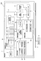
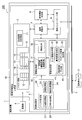
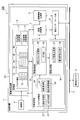
- FIG. 1 is a diagram showing a configuration of a sensing system 100 including an image processing device 50 according to the first embodiment.
- the sensing system 100 is a sensing system that uses an imaging device 1 mounted on a vehicle to image the surroundings of the vehicle, performs image recognition, and detects surrounding objects.
- the sensing system 100 is a system mounted on a motorcycle whose posture changes from moment to moment, but it can also be mounted on a four-wheeled vehicle such as an automobile.
- the sensing system 100 includes an image pickup device 1 that images the surroundings of the vehicle, a tilt angle sensor 2 that detects the tilt angle of the vehicle, and a communication bus 3 that connects the image pickup device 1 and the tilt angle sensor 2.
- the tilt angle sensor 2 is composed of, for example, an inertial measurement unit (IMU).
- the tilt angle sensor 2 detects a three-dimensional angle, angular velocity, and acceleration including the tilt angle of the vehicle.
- the tilt angle of the vehicle is at least one of a roll angle, a pitch angle, and a yaw angle.
- the roll angle indicates the amount of inclination of the vehicle when the vehicle is inclined with the z-axis extending in the front-rear direction of the vehicle as the rotation axis.
- the pitch angle indicates the amount of inclination of the vehicle when the vehicle is inclined with the x-axis extending in the left-right direction of the vehicle as the rotation axis.
- the yaw angle indicates the amount of inclination of the vehicle when the vehicle is inclined with the y-axis extending in the vertical direction of the vehicle as the rotation axis.
- a roll angle in which the vehicle is inclined with the front-rear direction of the vehicle as a rotation axis will be described as an example.
- the tilt angle sensor 2 encodes the detected information such as the tilt angle into a data format conforming to the communication protocol applied to the bus 3 such as CAN (Controller Area Network) and Ethernet, and performs image processing via the bus 3. It is transmitted to the device 50.
- the tilt angle is stored in the buffer area 10 described later in the storage unit 5.
- the tilt angle sensor 2 may be any sensor that can detect the tilt angle in real time, and is not limited to the inertial measurement unit.
- the image pickup device 1 includes an image pickup unit 4, a storage unit 5, an image processing unit 6, an image recognition unit 7, a control information generation unit 8, and a communication interface unit 9.
- the storage unit 5, the image processing unit 6, the image recognition unit 7, the control information generation unit 8, and the communication interface unit 9 are collectively referred to as an “image processing device 50”.
- the image pickup unit 4 is composed of a camera module including an image pickup element such as a CMOS (Complementary Metal Oxide Semiconductor) sensor and a lens unit.
- the camera module constituting the image pickup unit 4 is a so-called monocular camera, but may be a stereo camera.
- the image pickup unit 4 is mounted on the vehicle so as to face forward in the traveling direction of the vehicle, and inclines according to the inclination angle of the vehicle.
- the imaging unit 4 images the surroundings of the vehicle. When the image pickup unit 4 takes an image of the surroundings of the vehicle in a state where the vehicle is tilted, the imaging unit 4 acquires an image tilted according to the tilt angle of the vehicle. In the present embodiment, the image acquired by the imaging unit 4 is also referred to as an “image captured”.
- the image acquired by the image pickup unit 4 that is tilted according to the tilt angle of the vehicle is also referred to as an "image captured in a tilted state".
- the captured image is stored in the buffer area 10 of the
- the image processing device 50 processes the captured image acquired by the imaging unit 4, detects an object existing around the vehicle such as a road, a vehicle, a pedestrian, or an obstacle, and activates a brake or an accelerator. It is a device that generates control information and the like.
- the image processing device 50 is realized by the cooperation of hardware such as a microcomputer, FPGA (field-programmable gate array), and memory, and software including a program describing the contents of various processes.
- the storage unit 5 is composed of a memory that temporarily stores various types of information.
- the storage unit 5 has a plurality of storage areas.
- the plurality of storage areas included in the storage unit 5 include a buffer area 10 and a generated image storage area 11.
- the buffer area 10 is a storage area for storing the captured image acquired by the imaging unit 4 and the tilt angle transmitted by the tilt angle sensor 2.
- the buffer area 10 stores a captured image in an inclined state.
- the buffer area 10 corresponds to an example of the first storage area in the present invention.
- the generated image storage area 11 is a storage area for storing various images generated by the image processing unit 6.
- the image processing unit 6 performs image processing on the captured image stored in the storage unit 5 and generates a recognition image used for image recognition in the image recognition unit 7.
- the image processing unit 6 includes a buffer management unit 20, an image conversion unit 30, and an image generation unit 40.
- the buffer management unit 20 generates and manages the information stored in the buffer area 10 of the storage unit 5. Specifically, the buffer management unit 20 is stored in the buffer area 10, the time generation unit 23 which is composed of a timer and generates a time stamp, the image management unit 21 which manages the captured image stored in the buffer area 10. It has an inclination angle management unit 24 that manages the inclination angle. Further, the buffer management unit 20 has a synchronization management unit 22 that associates the captured image stored in the buffer area 10 with the tilt angle. Details of the processing of the buffer management unit 20 related to the association between the captured image and the tilt angle will be described later with reference to FIGS. 3 and 4.
- the image conversion unit 30 converts the tilted captured image stored in the buffer area 10 into a non-tilted captured image based on the tilt angle associated with the captured image.
- the image conversion unit 30 includes a rotation unit 31 that performs a rotation process for rotating the captured image in the tilted state stored in the buffer area 10, and an invalidation unit that invalidates the pixels whose information has been lost due to the rotation process. 32 and.
- the details of the processing of the image conversion unit 30 that converts the image captured in the tilted state into the captured image in the non-tilted state will be described later with reference to FIG.
- the image generation unit 40 generates a recognition image used for image recognition of the captured image. Specifically, the image generation unit 40 generates an edge image generation unit 41 that performs edge extraction processing on the captured image to generate an edge image, and a light / shade conversion process that performs light / shade conversion processing on the captured image to generate a light / shade image. It has a shading image generation unit 42. Each of the edge image and the light and shade image is one of the recognition images used for image recognition. The generated recognition image is stored in the generated image storage area 11 of the storage unit 5.
- the image generation unit 40 may generate a matching image as a recognition image in addition to the edge image and the shading image.
- the matching image is an image used when the image recognition unit 7 performs image recognition, and is an image obtained by cutting out a part from the captured image.
- the sensing system 100 can be provided with a radar that measures the position and distance of an object existing around the vehicle, and the information of the object including the measurement result of the radar is transmitted to the image processing device 50 via the bus 3. Can be sent.
- the image generation unit 40 identifies an object in the captured image (captured image in a non-tilted state) after the rotation process based on the measurement result of the radar, and captures a predetermined pixel region including the specified object after the rotation process.
- a matching image can be generated by cutting out from an image (captured image in a non-tilted state).
- the image recognition unit 7 uses the recognition image generated by the image processing unit 6 to perform image recognition of the captured image and detect an object around the vehicle. Specifically, the image recognition unit 7 reads out the recognition image stored in the generated image storage area 11 of the storage unit 5 and performs pattern recognition or the like from the characteristics of the recognition image to perform an object reflected in the captured image. To identify. Further, when performing image recognition, the image recognition unit 7 uses a matching image, which is one of the recognition images, to perform matching processing or the like with a machine-learned classifier of the image recognition unit 7. , The object reflected in the captured image can be identified. Further, the image recognition unit 7 tracks the movement of the identified object by performing tracking processing or the like using a plurality of recognition images generated from the plurality of captured images acquired at different imaging timings. As a result, the image recognition unit 7 can detect an object around the vehicle.
- the control information generation unit 8 generates control information necessary for vehicle running control, warning notification, etc., such as control information of an actuator that operates a brake or an accelerator, based on the detection result of the image recognition unit 7.
- the control information generated by the control information generation unit 8 is transmitted to a vehicle control device configured by an ECU (Electronic Control Unit) or the like.
- the communication interface unit 9 communicates with the tilt angle sensor 2 and the vehicle control device via the bus 3.
- the communication interface unit 9 encodes the control information generated by the control information generation unit 8 into a data format conforming to the above communication protocol applied to the bus 3 and transmits the control information to the vehicle control device.
- the communication interface unit 9 receives the message including the tilt angle transmitted from the tilt angle sensor 2, it decodes it into the data format of the image processing device 50 to acquire the tilt angle and outputs it to the image processing unit 6.
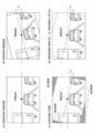
- FIG. 2 is a diagram illustrating the processing of the image conversion unit 30 shown in FIG.
- FIG. 2A is a diagram showing an example of a captured image in a non-tilted state.
- FIG. 2B is a diagram showing an example of a captured image in an inclined state.
- FIG. 2C is a diagram showing an example of an image obtained by rotating the image shown in FIG. 2B.
- FIG. 2D is a diagram showing another example of the image obtained by rotating the image shown in FIG. 2B.
- FIGS. 2A to 2D are captured images obtained by cutting out a part of the pixel area of the imaging unit 4 into a rectangle.
- FIG. 2A shows an image captured in the non-tilted state acquired by the imaging unit 4 when the vehicle is in the non-tilted state, and shows three preceding vehicles.
- FIG. 2B shows a captured image of the tilted state acquired by the imaging unit 4 in a state where the vehicle is tilted by the tilt angle ( ⁇ ) with respect to FIG. 2A. That is, in FIG. 2B, the captured image is tilted counterclockwise by an angle ⁇ with the z-axis extending in the front-rear direction of the vehicle passing through the point at infinity as the rotation axis.
- the captured image in the tilted state is stored in the buffer area 10 in association with the tilt angle ( ⁇ ).
- the rotating unit 31 of the image conversion unit 30 performs a rotation process of rotating the image captured in the tilted state shown in FIG. 2B according to the tilt angle ( ⁇ ) associated with the captured image. Specifically, the rotating unit 31 rotates by an angle ⁇ in the direction opposite to that of FIG. 2B (clockwise) with the z-axis extending in the front-rear direction of the vehicle passing through the point at infinity as the rotation axis.
- the captured image in the tilted state shown in FIG. 2 (b) is converted into the captured image in the non-tilted state as shown in FIG. 2 (c).
- the invalidation unit 32 of the image conversion unit 30 adds an invalid image such as a black image to the pixels whose information has been lost by the rotation processing, so that the information can be obtained by the rotation processing. Disable the lost pixel.
- this invalidation it is possible to suppress the occurrence of erroneous detection when performing image recognition on the captured image in the non-tilted state shown in FIG. 2C.
- the invalidation unit 32 may perform another process instead of the process of adding an invalid image as shown in FIG. 2 (c).
- the invalidation unit 32 is invalidated by cutting out a part of the pixel area of the image pickup unit 4 into a rectangle and setting the size of the cutout area when acquiring the captured image by enlarging it as follows.
- the process of adding an image can be replaced. That is, the invalidation unit 32 rotates the captured image at the maximum tilt angle (-90 degrees, 90 degrees) with the z-axis extending in the front-rear direction of the vehicle passing through the point at infinity as the rotation axis for the size of the cutout region.
- the image conversion unit 30 can convert the captured image in the tilted state into the captured image in the non-tilted state by rotating the captured image in the tilted state according to the tilt angle associated with the captured image.
- the image generation unit 40 can generate a recognition image in the non-tilted state from the captured image in the non-tilted state.
- the image processing device 50 can always perform image recognition of the captured image by using the recognition image in the non-tilted state even if the posture of the vehicle changes from moment to moment.
- the tilted image and the recognition image have many variations depending on the tilt angle even if the image shows the same object.
- the processing load of image recognition also increases because the dictionary becomes enormous. That is, performing image recognition with a captured image or a recognition image in an inclined state has a large burden as compared with performing image recognition with a captured image or a recognition image in a non-tilted state.
- the image processing device 50 can always perform image recognition on a non-tilted captured image or a recognition image even if the posture of the vehicle changes from moment to moment, the burden on image recognition can be reduced. .. Moreover, the image processing device 50 can use an image recognition engine for four-wheeled vehicles, which often performs image recognition based on a non-tilted captured image or a recognition image. Therefore, the image processing device 50 can easily reduce the burden of image recognition even if the posture of the vehicle changes from moment to moment.
- the image processing device 50 can convert the captured image in the tilted state into the captured image in the non-tilted state and generate the recognition image in the non-tilted state by a simple process called rotation processing, the vehicle Even if the posture changes from moment to moment, the burden related to image recognition can be reduced more easily.
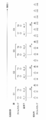
- FIG. 3 is a diagram illustrating the processing of the buffer management unit 20 shown in FIG.
- FIG. 4 is a diagram illustrating the buffer area 10 shown in FIG.
- the imaging unit 4 can acquire a plurality of captured images having different exposure times for each predetermined imaging cycle.
- the imaging unit 4 comprises a normal captured image captured at a normal exposure time at a certain imaging timing and a special captured image captured at a special exposure time different from the normal exposure time.
- Two captured images can be acquired.
- a normal captured image is, for example, an image as shown in FIG. 2A or FIG. 2B, and is an object existing around the vehicle such as a road marking line or shape, a vehicle, a pedestrian, or an obstacle. It is a captured image acquired to detect.
- the special captured image is a captured image acquired to detect color information of a vehicle tail lamp, a traffic light, an electric bulletin board, or the like.
- the normal captured image and the special captured image are stored in the buffer area 10 of the storage unit 5 as shown by reference numeral 15 in FIG.
- the imaging unit 4 can acquire a plurality of captured images in addition to the normal captured image and the special captured image.
- the image management unit 21 of the buffer management unit 20 adds a time stamp generated by the time generation unit 23 to the captured image stored in the buffer area 10.
- the image management unit 21 adds a time stamp indicating the time when the captured image is stored in the buffer area 10 to the captured image.
- FIG. 3 shows an example in which time stamps indicating times T1 to T8 are added to the captured image in the order in which the captured images are stored in the buffer area 10.
- the time stamp added to the captured image is stored in the buffer area 10 of the storage unit 5 in a one-to-one correspondence with the captured image, as shown by reference numeral 14 in FIG.
- the image management unit 21 manages a plurality of captured images acquired at predetermined imaging cycles as a group. That is, the plurality of captured images included in one group are images captured by the imaging unit 4 at the same imaging timing.
- one group includes two captured images, a normal captured image and a special captured image.
- the group G1 includes a normal captured image with a time stamp indicating the time T1 and a special captured image with a time stamp indicating the time T2.
- Group G2 includes a normal captured image with a time stamp indicating the time T3 and a special captured image with a time stamp indicating the time T4.
- Group G3 includes a normal captured image with a time stamp indicating the time T5 and a special captured image with a time stamp indicating the time T6.
- Group G4 includes a normal captured image with a time stamp indicating the time T7 and a special captured image with a time stamp indicating the time T8. The difference between the plurality of groups can be discriminated from the attribute information added to the captured image by the imaging unit 4 when the captured image is acquired, even if the imaging cycle is extremely short.
- the image management unit 21 adds an identifier to the captured image stored in the buffer area 10 so that the group to which the captured image belongs can be identified.
- the identifier i1-1 is added to the normal captured image to which the time stamp indicating the time T1 is added
- the identifier i1-2 is added to the special captured image to which the time stamp indicating the time T2 is added.
- the identifier i2_1 is added to the normal captured image to which the time stamp indicating the time T3 is added
- the identifier i2_1 is added to the special captured image to which the time stamp indicating the time T4 is added.
- the identifier i3_1 is added to the normal captured image to which the time stamp indicating the time T5 is added, and the identifier i3_2 is added to the special captured image to which the time stamp indicating the time T6 is added.
- the identifier i4_1 is added to the normal captured image to which the time stamp indicating the time T7 is added, and the identifier i4-2 is added to the special captured image to which the time stamp indicating the time T8 is added.
- the identifier added to the captured image is stored in the buffer area 10 of the storage unit 5 in a one-to-one correspondence with the captured image, as shown by reference numeral 16 in FIG.
- the tilt angle sensor 2 detects the tilt angle at a predetermined detection cycle and transmits it to the image processing device 50 via the bus 3.
- the detection cycle of the tilt angle sensor 2 may be the same as or different from the imaging cycle of the imaging unit 4. In the present embodiment, the detection cycle of the tilt angle sensor 2 will be described as being shorter than the imaging cycle of the imaging unit 4.
- the tilt angle transmitted from the tilt angle sensor 2 is stored in the buffer area 10 of the storage unit 5 as indicated by reference numeral 13 in FIG.
- the tilt angle management unit 24 of the buffer management unit 20 adds a time stamp generated by the time generation unit 23 to the tilt angle stored in the buffer area 10.
- the tilt angle management unit 24 adds a time stamp indicating the time when the tilt angle is stored in the buffer area 10 to the tilt angle.
- FIG. 3 shows an example in which time stamps indicating times t1 to t16 are added to the tilt angle according to the order in which the tilt angles are stored in the buffer area 10.
- the time stamp added to the tilt angle is stored in the buffer area 10 of the storage unit 5 in a one-to-one correspondence with the tilt angle, as shown by reference numeral 12 in FIG.
- the synchronization management unit 22 of the buffer management unit 20 associates the same tilt angle with a plurality of captured images managed as a group by the image management unit 21. That is, the synchronization management unit 22 associates the same tilt angle with a plurality of images captured by the imaging unit 4 at the same imaging timing.
- the transmission distance of the tilt angle transmitted from the tilt angle sensor 2 via the bus 3 and stored in the buffer area 10 is the transmission of the captured image stored in the buffer area 10 from the imaging unit 4 without passing through the bus 3.
- the first required time required from the detection of the tilt angle by the tilt angle sensor 2 to the storage in the buffer area 10 is from the acquisition of the captured image by the imaging unit 4 to the storage in the buffer area 10. It will be longer than the second required time required for. Assuming that the time obtained by subtracting the second required time from the first required time is the time difference ⁇ t, the tilt angle detected by the tilt angle sensor 2 at the same time as the time when the captured image is acquired by the imaging unit 4 is the captured image.
- the synchronization management unit 22 associates the captured image stored in the buffer area 10 with the tilt angle based on the time difference ⁇ t.
- the synchronization management unit 22 specifies one time from each time when a plurality of captured images managed as a group are stored in the buffer area 10. For example, the synchronization management unit 22 identifies the earliest time among the times when a plurality of captured images managed as a group are stored in the buffer area 10. In the example of FIG. 3, the time T1 is specified for the group G1, the time T3 is specified for the group G2, the time T5 is specified for the group G3, and the time T7 is specified for the group G4. Then, the synchronization management unit 22 calculates a predetermined time for each group by adding the above time difference ⁇ t to the specified time.
- the synchronization management unit 22 compares the calculated predetermined time with the time when the inclination angle is stored in the buffer area 10.
- the synchronization management unit 22 searches for the tilt angle stored in the buffer area 10 at the time closest to the predetermined time among the times when the tilt angle is stored in the buffer area 10.
- the synchronization management unit 22 associates the searched inclination angle with a plurality of captured images included in the group corresponding to a predetermined time.
- the tilt angle (angle3) to which the time stamp indicating the time t3 closest to the predetermined time (T1 + ⁇ t) obtained by adding the time difference ⁇ t to the specified time T1 is added is the predetermined time (angle3). It is associated with an captured image (image1_1) and a special captured image (image1-2) to which a time stamp indicating the time T1 from which T1 + ⁇ t) is calculated is added.
- the synchronization management unit 22 holds the addresses of the locations in the buffer area 10 where the tilt angles associated with each other and the plurality of captured images are stored.
- the synchronization management unit 22 has the time from when the tilt angle is detected by the tilt angle sensor 2 until it is stored in the buffer area 10, and the buffer area after the captured image in the tilt state is acquired by the image pickup unit 4. Based on the time difference ⁇ t from the time until it is stored in 10, the captured image in the tilted state stored in the buffer area 10 and the tilt angle can be associated with each other. As a result, the image processing device 50 can appropriately synchronize the image captured in the tilted state acquired at a certain imaging timing with the tilt angle detected at the detection timing at the same time as the imaging timing.
- the image processing device 50 erroneously recognizes the image captured in the tilted state as a non-tilted captured image, generates an image for recognizing the tilted state, and performs image recognition. There is a high possibility of obtaining the recognition result.
- the image processing device 50 can appropriately synchronize the captured image in the tilted state with the tilted angle, the image processing device 50 converts the captured image in the tilted state into the captured image in the non-tilted state in real time to recognize the non-tilted state.
- the image for use can be generated, and the correct recognition result can always be obtained. Therefore, the image processing device 50 can obtain stable recognition performance even if the posture of the vehicle changes from moment to moment.
- the image processing device 50 manages a plurality of captured images having different exposure times for each imaging cycle as a group, and manages the plurality of captured images as a group and tilts the plurality of captured images managed as a group. It can be associated with a corner. As a result, the image processing device 50 detects the plurality of captured images acquired at a certain imaging timing and the detection at the same time as the imaging timing, even when a plurality of captured images having different exposure times are acquired for each imaging cycle. It is possible to properly synchronize with the tilt angle detected at the timing.
- the image processing device 50 can convert the captured image in the tilted state into the captured image in the non-tilted state in real time to generate the recognition image in the non-tilted state, and can always obtain the correct recognition result. .. Moreover, since image recognition is performed using a plurality of captured images having different exposure times, the recognition performance can be improved. Therefore, the image processing device 50 can obtain stable and high recognition performance even if the posture of the vehicle changes from moment to moment.
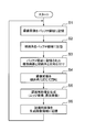
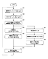
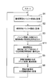
- FIG. 5 is a flowchart showing a flow of processing performed by the image processing device 50 shown in FIG.
- step S1 the image processing device 50 stores the captured image acquired by the imaging unit 4 in the buffer area 10 of the storage unit 5.
- the image processing device 50 adds a time stamp and an identifier to the captured image, and stores the captured image at a predetermined address location in the buffer area 10.
- step S2 the image processing device 50 stores the tilt angle transmitted by the tilt angle sensor 2 in the buffer area 10.
- the image processing device 50 receives the message including the tilt angle transmitted from the tilt angle sensor 2 via the bus 3, the image processing device 50 decodes it by the communication interface unit 9 to acquire the tilt angle and stores it in the buffer area 10.
- the image processing device 50 adds a time stamp to the tilt angle and stores it at a predetermined address location in the buffer area 10.
- step S3 the image processing device 50 associates the captured image stored in the buffer area 10 with the tilt angle based on the predetermined time difference ⁇ t.
- the image processing device 50 searches for the tilt angle stored in the buffer area 10 at the time closest to a predetermined time (T + ⁇ t) obtained by adding the time difference ⁇ t to the time T in which the captured image is stored in the buffer area 10.
- the image processing device 50 associates the searched inclination angle with the captured image stored in the buffer area 10 at the time T that is the calculation source of the predetermined time (T + ⁇ t).
- step S4 the image processing device 50 rotates the captured image in the tilted state stored in the buffer area 10 according to the tilt angle associated with the captured image.
- the image processing device 50 reads out the tilt angles and the captured images associated with each other from the buffer area 10 and performs rotation processing.
- the image processing device 50 specifies the address of the location of the buffer area 10 in which the captured image and the tilt angle associated with each other are stored, and reads out the captured image and the tilt angle.
- the image processing device 50 can convert the captured image in the tilted state into the captured image in the non-tilted state by rotating the read captured image according to the read tilt angle.
- step S5 the image processing device 50 generates a non-tilted state recognition image from the captured image (non-tilted state captured image) after the rotation process.
- the generated recognition image is, for example, an edge image or a shading image, but the image processing device 50 may generate another recognition image such as a matching image.
- step S6 the image processing device 50 stores the generated recognition image in the generated image storage area 11 of the storage unit 5. After that, the image processing device 50 can detect an object around the vehicle by reading out the recognition image stored in the generated image storage area 11 and performing image recognition using the recognition image. The image processing device 50 repeats the processing shown in FIG. 5 at predetermined imaging cycles of the imaging unit 4.
- the image processing apparatus 50 As described above, in the image processing apparatus 50 according to the present embodiment, the time from when the tilt angle is detected by the tilt angle sensor 2 until it is stored in the buffer area 10 and the captured image in the tilted state are captured by the image pickup unit 4. Based on the time difference ⁇ t from the time from acquisition to storage in the buffer area 10, the captured image in the tilted state stored in the buffer area 10 is associated with the tilt angle. Then, the image processing device 50 according to the present embodiment converts the captured image in the tilted state stored in the buffer area 10 into a non-tilted captured image based on the tilt angle associated with the captured image. To generate a recognition image in a non-tilted state.
- the image processing device 50 according to the present embodiment can appropriately synchronize the captured image in the tilted state with the tilt angle even if the posture of the vehicle changes from moment to moment like a motorcycle.
- the image captured in the tilted state can always be converted into the captured image in the non-tilted state to generate the recognition image in the non-tilted state. Therefore, the image processing device 50 according to the present embodiment can always perform image recognition using the recognition image in the non-tilted state even if the posture of the vehicle changes from moment to moment. Therefore, the image processing device 50 according to the present embodiment can easily reduce the burden related to image recognition even if the posture of the vehicle changes from moment to moment, and can obtain stable recognition performance.
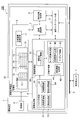
- FIG. 6 is a diagram showing a configuration of a sensing system 100 provided with an image processing device 50 in the second embodiment.
- the imaging unit 4 is composed of a stereo camera. That is, the imaging unit 4 according to the second embodiment is composed of a pair of camera modules arranged at intervals in the left-right direction of the vehicle, and acquires a pair of captured images having parallax.
- the image processing device 50 stores the pair of captured images in the tilted state and the tilt angle in association with each other in the buffer area 10 of the storage unit 5.
- the synchronization management unit 22 of the buffer management unit 20 associates the pair of captured images in the tilted state with the tilt angle.
- the image generation unit 40 has a parallax image generation unit 44.
- the parallax image generation unit 44 acquires the parallax for each pixel in the pair of captured images, and acquires the distance information in the depth direction from the image capturing unit 4 toward the front of the vehicle from the acquired parallax.
- the parallax image generation unit 44 can map the distance information acquired for each pixel and generate a parallax image.
- the parallax image generation unit 44 generates a parallax image in the tilted state from a pair of captured images in the tilted state stored in the buffer area 10.
- the image conversion unit 30 rotates a pair of captured images in a tilted state stored in the buffer area 10 according to a tilt angle associated with the pair of captured images, so that the image conversion unit 30 is in a non-tilted state. Convert to a pair of captured images.
- the image conversion unit 30 converts the tilted parallax image into a non-tilted parallax image by rotating it according to the tilt angle associated with the pair of captured images that are the generation sources of the tilted image.
- the image generation unit 40 has a matching image generation unit 43.
- the matching image generation unit 43 generates the above-mentioned matching image, which is one of the recognition images.
- the matching image generation unit 43 generates a non-tilted matching image by using a pair of non-tilted captured images and a non-tilted parallax image converted by the image conversion unit 30.
- the matching image generation unit 43 identifies the position of an object in one of a pair of non-tilted captured images based on the distance information included in the non-tilted parallax image.
- the matching image generation unit 43 can generate a matching image in a non-tilted state by cutting out a predetermined pixel region including a specified object from one of a pair of non-tilted captured images.
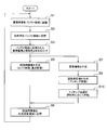
- FIG. 7 is a flowchart showing a flow of processing performed by the image processing device 50 shown in FIG.
- the image processing apparatus 50 performs the same processing as in steps S1 to S6 shown in FIG. 5 in steps S1 to S6 shown in FIG. 7. However, in step S5 shown in FIG. 7, the image processing apparatus 50 uses one of the pair of captured images after the rotation process (one of the pair of captured images in the non-tilted state) as a recognition image such as an edge image or a shading image. To generate. Further, the image processing apparatus 50 performs the processes of steps S7 to S9 in parallel with the processes of steps S4 to S5 after step S3.
- step S7 the image processing device 50 generates a parallax image in the tilted state from the pair of captured images in the tilted state stored in the buffer area 10.
- step S8 the image processing device 50 rotates the generated parallax image in the tilted state according to the tilt angle associated with the pair of captured images that are the generation sources of the parallax image. As a result, the image processing device 50 can convert the parallax image in the tilted state into the parallax image in the non-tilted state.
- step S9 the image processing device 50 uses one of the pair of captured images after the rotation process (one of the pair of non-tilted captured images) and the parallax image after the rotation process (the parallax image in the non-tilted state).
- a matching image is generated as a recognition image.
- the image processing device 50 proceeds to step S6 and stores the matching image, which is one of the generated recognition images, in the generated image storage area 11 of the storage unit 5.
- An edge image, a shading image, and a matching image in a non-tilted state are stored in the generated image storage area 11.
- the image processing device 50 repeats the processing shown in FIG. 7 at each predetermined imaging cycle of the imaging unit 4.
- the image processing device 50 according to the second embodiment is a pair of tilted images stored in the buffer area 10 as in the first embodiment, even when the image pickup unit 4 is configured by a stereo camera. And the tilt angle. Then, as in the first embodiment, the image processing device 50 according to the second embodiment uses the pair of captured images in the tilted state stored in the buffer area 10 based on the tilt angle associated with the pair of captured images. Then, it is converted into a pair of images captured in the non-tilted state to generate a recognition image in the non-tilted state.
- the image processing device 50 according to the second embodiment always performs image recognition with a non-tilted captured image or a recognition image even if the posture of the vehicle changes from moment to moment, as in the first embodiment. Can be done. Therefore, the image processing device 50 according to the second embodiment can easily reduce the burden related to the image recognition and stable recognition even if the posture of the vehicle changes from moment to moment, as in the first embodiment. Performance can be obtained.
- FIG. 8 is a diagram showing a configuration of a sensing system 100 including the image processing device 50 according to the third embodiment.
- the number of pixels of the image pickup element included in the image pickup unit 4 tends to increase like 4K or 8K of the image standard in order to improve the detection accuracy of a distant sign or the like, and the number of pixels of the image pickup image tends to increase. Tends to increase. As the number of pixels of the captured image increases, the processing load related to the rotation processing of the captured image and the parallax image increases, so it is desirable to reduce the rotation processing. On the other hand, if the matching image used when the image recognition unit 7 performs image recognition remains in the tilted state, a huge amount of learning images covering a large number of variations due to the difference in the tilt angle are prepared, and this is image recognition. It is necessary to train the classifier of Part 7 to create a dictionary.
- the image processing device 50 according to the third embodiment maintains the tilted state of the pair of captured images, the parallax image, the edge image, and the shading image, and performs rotation processing only on the matching image. Since the image processing device 50 according to the third embodiment performs rotation processing only on the matching image, it is possible to suppress an increase in the processing load and omit the invalidating unit 32 of the image conversion unit 30, which is simple. Can be configured.
- the image processing device 50 stores the pair of captured images in the tilted state and the tilt angle in association with each other in the buffer area 10 of the storage unit 5, as in the second embodiment.
- a parallax image in the tilted state is generated from a pair of captured images in the tilted state.
- the image generation unit 40 generates a matching image in the tilted state by using the pair of captured images in the tilted state and the parallax image in the tilted state in the matching image generation unit 43.
- the image conversion unit 30 rotates the matching image in the tilted state generated by the image generation unit 40 according to the tilt angle associated with the pair of captured images that are the generation sources of the matching image, thereby causing non-tilt. Convert to a matching image of the state.
- FIG. 9 is a flowchart showing a flow of processing performed by the image processing device 50 shown in FIG.
- the image processing apparatus 50 according to the third embodiment performs the same processing as in steps S1 to S3, S5 to S7, and S9 shown in FIG. 7 in steps S1 to S3, S5 to S7, and S9 shown in FIG.
- the image processing apparatus 50 according to the third embodiment does not perform steps S4 and S8 shown in FIG.
- step S5 shown in FIG. 9 the image processing device 50 generates an edge image or a shading image in the tilted state as a recognition image from one of the pair of captured images in the tilted state.
- step S9 shown in FIG. 9 the image processing device 50 generates a matching image in the tilted state as a recognition image by using the pair of captured images in the tilted state and the parallax image in the tilted state.
- step S10 the image processing device 50 rotates the generated matching image in the tilted state according to the tilt angle associated with the pair of captured images that are the generation sources of the matching image. As a result, the image processing device 50 can convert the matching image in the tilted state into the matching image in the non-tilted state.
- the image processing device 50 proceeds to step S6 and stores the matching image, which is one of the generated recognition images, in the generated image storage area 11 of the storage unit 5. In the generated image storage area 11, an edge image and a shading image in a tilted state, and a matching image in a non-tilted state are stored. After that, the image processing device 50 repeats the processing shown in FIG. 9 at each predetermined imaging cycle of the imaging unit 4.
- the image processing device 50 associates the pair of captured images in the tilted state stored in the buffer area 10 with the tilt angle, as in the second embodiment. Then, unlike the second embodiment, the image processing apparatus 50 according to the third embodiment generates a matching image in the tilted state from a pair of captured images in the tilted state stored in the buffer area 10, and then generates a matching image in the tilted state. Is rotated to convert it into a matching image in a non-tilted state.
- the image processing device 50 according to the third embodiment can always perform image recognition with the recognition image in the non-tilted state even if the posture of the vehicle changes from moment to moment. Further, since the image processing apparatus 50 according to the third embodiment performs rotation processing only on the matching image, it is possible to suppress an increase in the processing load even if the number of pixels of the image sensor increases, and the configuration is simple. Can be done. Therefore, the image processing device 50 according to the third embodiment can more easily reduce the burden related to image recognition and can obtain stable recognition performance.
- FIG. 10 is a diagram showing a configuration of a sensing system 100 including the image processing device 50 according to the fourth embodiment.
- FIG. 11 is a diagram illustrating the processing of the image conversion unit 30 shown in FIG.
- FIG. 11A is a diagram illustrating a method of reading out each pixel value of the pixel region cut out from the captured image in the inclined state.
- FIG. 11B is a diagram illustrating a method of writing each pixel value read by the method shown in FIG. 11A to the storage unit 5.
- the image conversion unit 30 when the image conversion unit 30 performs the image rotation processing, the coordinates of the image are converted according to the tilt angle, so that the image after the rotation processing may be distorted. Therefore, in the image processing device 50 according to the fourth embodiment, the image conversion unit 30 has an inclined address calculation unit 35 and a cutting unit 36 instead of the rotation unit 31 and the invalidation unit 32 that perform rotation processing. Cut out the image. Further, in the image processing device 50 according to the fourth embodiment, the storage unit 5 has a cut-out image storage area 17 which is a storage area different from the buffer area 10. The cut-out image storage area 17 corresponds to an example of the second storage area in the present invention.
- the image conversion unit 30 cuts out a part of the captured image from the captured image in the tilted state stored in the buffer area 10 according to the tilt angle associated with the captured image, and cuts the image. As the output image, it is stored in the cutout image storage area 17.
- the tilt address calculation unit 35 of the image conversion unit 30 calculates the address of the pixel region cut out as a cutout image from the captured image in the tilted state.
- the pixel region to be cut out is a rectangular region, and as shown in FIG. 11A, is a region inclined according to the inclination angle ( ⁇ ) detected by the inclination angle sensor 2.
- the tilted address calculation unit 35 includes the address of the leftmost pixel ( ⁇ 1) and the address of the rightmost pixel ( ⁇ 2) of the pixel area to be cut out, the size ( ⁇ , ⁇ ) of the pixel area to be cut out, and the pixel area to be cut out.
- the reading direction indicating the order of the pixels for reading the pixel value is set.
- the tilt address calculation unit 35 sets the read direction to a direction that is tilted by a tilt angle ( ⁇ ) with respect to the left-right direction (or vertical direction) of the captured image, which is the default horizontal read direction (or vertical read direction). ..
- the arrow directions of (1) to (5) indicate the reading direction, and after the reading of each pixel value is completed in the arrow direction of (1), (2) to (2) to It is shown that each pixel value is read out in order in each arrow direction of (5). Then, the inclined address calculation unit 35 calculates the address of each pixel arranged in order along the set reading direction.
- the cutout unit 36 of the image conversion unit 30 designates the addresses calculated by the inclined address calculation unit 35 in the order along the reading direction, and reads out each pixel value of the cutout pixel area. Then, the cutout unit 36 writes each read pixel value in the cutout image storage area 17 in the order along the read direction.
- the arrow directions (1') to (5') indicate the writing direction, correspond to each of the reading directions (1) to (5), and are the default horizontal. It is set in the same direction as the horizontal direction (or vertical direction) of the captured image, which is the reading direction (or vertical reading direction). In the example of FIG.
- the cutout portion 36 can convert the captured image in the tilted state into the cutout image in the non-tilted state, similar to the image subjected to the rotation processing.
- the image generation unit 40 generates a recognition image such as a non-tilted edge image or a shading image from the non-tilted cutout image stored in the cutout image storage area 17.
- FIG. 12 is a flowchart showing a flow of processing performed by the image processing device 50 shown in FIG.
- the image processing apparatus 50 according to the fourth embodiment performs the same processing as in steps S1 to S3, S5, and S6 shown in FIG. 5 in steps S1 to S3 and S5 and 6 shown in FIG.
- the image processing apparatus 50 according to the fourth embodiment performs step S11 instead of step S4 shown in FIG.
- step S11 the image processing device 50 cuts out a part of the captured image in the tilted state stored in the buffer area 10 according to the tilt angle associated with the captured image, and uses it as a cutout image. Write to the cutout image storage area 17. As a result, the image processing device 50 can convert the captured image in the tilted state into the cutout image in the non-tilted state. After that, the image processing device 50 proceeds to step S5 and generates a non-tilted state recognition image from the non-tilted cutout image stored in the cutout image storage area 17.
- the generated recognition image is, for example, an edge image or a shading image, but the image processing device 50 may generate another recognition image such as a matching image.
- the image processing device 50 proceeds to step S6 and stores the generated recognition image in the generated image storage area 11. After that, the image processing device 50 repeats the processing shown in FIG. 12 at each predetermined imaging cycle of the imaging unit 4.
- the image processing device 50 according to the fourth embodiment associates the captured image in the tilted state stored in the buffer area 10 with the tilt angle, as in the first embodiment. Then, unlike the first embodiment, the image processing device 50 according to the fourth embodiment uses the captured image in the tilted state stored in the buffer area 10 according to the tilt angle associated with the captured image. By cutting out a part of the image and writing it as a cut-out image in the cut-out image storage area 17, the captured image in the tilted state is converted into the cut-out image in the non-tilted state. Then, the image processing device 50 according to the fourth embodiment generates a recognition image in the non-tilted state from the cutout image in the non-tilted state.
- the image processing device 50 according to the fourth embodiment can always perform image recognition with the recognition image in the non-tilted state even if the posture of the vehicle changes from moment to moment. Further, since the image processing apparatus 50 according to the fourth embodiment performs the cutting process instead of the rotation process, it is possible to suppress distortion that occurs in the image after the rotation process. Therefore, the image processing device 50 according to the fourth embodiment can easily reduce the burden related to image recognition and can obtain stable recognition performance.
- the image conversion unit 30 has a tilt address calculation unit 35 and a cutout unit 36 instead of the rotation unit 31 and the invalidation unit 32, instead of the rotation processing.
- the cutout process may be performed in combination with the rotation process, and the image processing device 50 according to the first to third embodiments, together with the rotation unit 31 and the invalidation unit 32, has the inclination address calculation unit 35 and the cutout process. It may have a protrusion 36.
- the present invention is not limited to the above embodiment, and includes various modifications.
- the above-described embodiment has been described in detail in order to explain the present invention in an easy-to-understand manner, and is not necessarily limited to those having all the described configurations.
- it is possible to replace a part of the configuration of one embodiment with the configuration of another embodiment and it is also possible to add the configuration of another embodiment to the configuration of one embodiment.
- each of the above configurations, functions, processing units, processing means, etc. may be realized by hardware by designing a part or all of them by, for example, an integrated circuit. Further, each of the above configurations, functions, and the like may be realized by software by the processor interpreting and executing a program that realizes each function. Information such as programs, tapes, and files that realize each function can be placed in a memory, a hard disk, a recording device such as an SSD (Solid State Drive), or a recording medium such as an IC card, an SD card, or a DVD.
- SSD Solid State Drive
- control lines and information lines indicate what is considered necessary for explanation, and not all control lines and information lines are necessarily shown on the product. In practice, it can be considered that almost all configurations are interconnected.
Landscapes
- Engineering & Computer Science (AREA)
- Physics & Mathematics (AREA)
- General Physics & Mathematics (AREA)
- Theoretical Computer Science (AREA)
- Multimedia (AREA)
- Computer Vision & Pattern Recognition (AREA)
- Traffic Control Systems (AREA)
- Image Processing (AREA)
- Image Analysis (AREA)
Abstract
車両の姿勢が時々刻々と変化しても、画像認識に係る負担を容易に軽減でき、安定した認識性能を得ることが可能な画像処理装置を提供する。画像処理装置50は、車両に搭載された撮像部4により取得された撮像画像と、車両の傾斜角を検出する傾斜角センサ2から送信された傾斜角とを記憶する記憶部5と、撮像画像について画像処理を行う画像処理部6とを備える。画像処理部6は、傾斜状態の撮像画像が撮像部4により取得されてから記憶部5に記憶されるまでの時間と、傾斜角が傾斜角センサ2により検出されてから記憶部5に記憶されるまでの時間との時間差Δtに基づいて、傾斜状態の撮像画像と傾斜角とを対応付ける。画像処理部6は、傾斜状態の撮像画像から、当該撮像画像に対応付けられた傾斜角に基づいて、撮像画像の画像認識に用いられる非傾斜状態の認識用画像を生成することを特徴とする。
Description
本発明は、画像処理装置に関する。
安全且つ快適な車社会を実現するため、運転支援システムや予防安全システムの導入が進んでいる。例えば、設定された車速内にて前方車両との車間距離を保ちながら追従走行を行うACC(Adaptive Cruise Control)は、多くの四輪車に導入されている。これらのシステムでは、車両に搭載された撮像装置により車両の周囲を撮像し、画像認識を行って周囲の物体を検知するセンシング技術が使用されている。
二輪車では、四輪車と異なり、車両を傾けてカーブした道路を走行する等、車両の姿勢が時々刻々と変化する。二輪車に対して上記のセンシング技術を使用する場合、車両の傾斜に伴って撮像装置により取得される画像の傾斜状態が時々刻々と変化するため、画像認識に係る負担が大きい。
撮像装置により取得される画像の傾斜状態が変化する点に対応する技術として、例えば、特許文献1に記載された技術がある。特許文献1には、所定範囲を撮像し撮像データを出力する撮像手段と、撮像データの一部を記憶する記憶手段と、二輪車の傾斜角度を検出し傾斜角データを出力する検出手段と、傾斜角データに応じて記憶手段に記憶させる撮像データの一部を抽出する制御手段とを備えた二輪車用ドライブレコーダ装置が記載されている。
しかしながら、特許文献1に記載の技術には、撮像データと傾斜角データとの対応関係を明らかにする点については何ら考慮されていない。このため、車両の傾斜に伴って撮像データの傾斜状態が時々刻々と変化する場合、特許文献1に記載の技術では、記憶手段に記憶させる撮像データの一部を傾斜角データに応じて適切に抽出することは困難である。
よって、特許文献1に記載の技術を、上記のセンシング技術に適用しても、安定した認識性能を得ることは困難である。
よって、特許文献1に記載の技術を、上記のセンシング技術に適用しても、安定した認識性能を得ることは困難である。
本発明は、上記に鑑みてなされたものであり、車両の姿勢が時々刻々と変化しても、画像認識に係る負担を容易に軽減でき、安定した認識性能を得ることが可能な画像処理装置を提供することを目的とする。
上記課題を解決するために、本発明に係る画像処理装置は、車両に搭載された撮像部により取得された撮像画像と、前記車両の傾斜角を検出する傾斜角センサから送信された前記傾斜角とを記憶する記憶部と、前記記憶部に記憶された前記撮像画像について画像処理を行う画像処理部とを備え、前記記憶部は、前記車両の前記傾斜角に応じて傾斜した前記撮像部により取得された傾斜状態の前記撮像画像を記憶し、前記画像処理部は、前記傾斜角が前記傾斜角センサにより検出されてから前記記憶部に記憶されるまでの時間と、前記傾斜状態の前記撮像画像が前記撮像部により取得されてから前記記憶部に記憶されるまでの時間との時間差に基づいて、前記記憶部に記憶された前記傾斜状態の前記撮像画像と前記傾斜角とを対応付け、前記記憶部に記憶された前記傾斜状態の前記撮像画像から、当該撮像画像に対応付けられた前記傾斜角に基づいて、前記撮像画像の画像認識に用いられる非傾斜状態の認識用画像を生成することを特徴とする。
本発明によれば、車両の姿勢が時々刻々と変化しても、画像認識に係る負担を容易に軽減でき、安定した認識性能を得ることが可能な画像処理装置を提供することができる。
上記以外の課題、構成および効果は、以下の実施形態の説明により明らかにされる。
上記以外の課題、構成および効果は、以下の実施形態の説明により明らかにされる。
以下、本発明の実施形態について図面を用いて説明する。なお、各実施形態において同一の符号を付された構成は、特に言及しない限り、各実施形態において同様の機能を有するため、その説明を省略する。
[実施形態1]
図1は、実施形態1に係る画像処理装置50を備えたセンシングシステム100の構成を示す図である。
図1は、実施形態1に係る画像処理装置50を備えたセンシングシステム100の構成を示す図である。
センシングシステム100は、車両に搭載された撮像装置1により車両の周囲を撮像し、画像認識を行って周囲の物体を検知するセンシングシステムである。センシングシステム100は、車両の姿勢が時々刻々と変化する自動二輪車に搭載されたシステムであるが、自動車等の四輪車に搭載して使用することも可能である。
センシングシステム100は、車両の周囲を撮像する撮像装置1と、車両の傾斜角を検出する傾斜角センサ2と、撮像装置1と傾斜角センサ2とを接続する通信用のバス3とを備える。
傾斜角センサ2は、例えば、慣性計測装置(IMU:Inertial Measurement Unit)により構成される。傾斜角センサ2は、車両の傾斜角を含む3次元の角度、角速度及び加速度を検出する。車両の傾斜角とは、ロール角、ピッチ角及びヨー角の少なくとも1つである。ロール角は、車両の前後方向に延びるz軸を回転軸として車両が傾斜する際の車両の傾斜量を示す。ピッチ角は、車両の左右方向に延びるx軸を回転軸として車両が傾斜する際の車両の傾斜量を示す。ヨー角は、車両の上下方向に延びるy軸を回転軸として車両が傾斜する際の車両の傾斜量を示す。本実施形態では、車両の傾斜角として、車両の前後方向を回転軸として傾斜するロール角を例に挙げて説明する。
傾斜角センサ2は、検出された傾斜角等の情報を、CAN(Controller Area Network)やEthernet等のバス3に適用された通信プロトコルに準じたデータ形式にエンコードし、バス3を介して画像処理装置50へ送信する。傾斜角は、記憶部5の後述するバッファ領域10に記憶される。なお、傾斜角センサ2は、リアルタイムに傾斜角を検出可能なセンサであればよく、慣性計測装置に限定されない。
撮像装置1は、撮像部4と、記憶部5と、画像処理部6と、画像認識部7と、制御情報生成部8と、通信インターフェース部9とを備える。本実施形態では、記憶部5と、画像処理部6と、画像認識部7と、制御情報生成部8と、通信インターフェース部9とを纏めて、「画像処理装置50」とも称する。
撮像部4は、CMOS(Complementary Metal Oxide Semiconductor)センサ等の撮像素子とレンズユニットとを含むカメラモジュールにより構成される。撮像部4を構成するカメラモジュールは、いわゆる単眼カメラであるが、ステレオカメラであってもよい。撮像部4は、車両の進行方向前方を向くように車両に搭載されており、車両の傾斜角に応じて傾斜する。撮像部4は、車両の周囲を撮像する。撮像部4は、車両が傾斜した状態にて車両の周囲を撮像すると、当該車両の傾斜角に応じて傾斜した画像を取得する。本実施形態では、撮像部4により取得された画像を「撮像画像」とも称する。車両の傾斜角に応じて傾斜した撮像部4により取得された画像を「傾斜状態の撮像画像」とも称する。撮像画像は、記憶部5のバッファ領域10に記憶される。
画像処理装置50は、撮像部4により取得された撮像画像を処理して、道路、車両、歩行者又は障害物等の車両の周囲に存在する物体を検知し、ブレーキやアクセルを作動させるアクチュエータの制御情報等を生成する装置である。画像処理装置50は、マイクロコンピュータ、FPGA(field-programmable gate array)、メモリ等のハードウェアと、各種処理の内容を記述したプログラムを含むソフトウェアとの協働によって実現される。
記憶部5は、各種情報を一時的に記憶するメモリにより構成される。記憶部5は、複数の記憶領域を有する。記憶部5が有する複数の記憶領域は、バッファ領域10と、生成画像記憶領域11とを含む。バッファ領域10は、撮像部4により取得された撮像画像と、傾斜角センサ2により送信された傾斜角とを記憶する記憶領域である。バッファ領域10は、傾斜状態の撮像画像を記憶する。バッファ領域10は、本発明における第1記憶領域の一例に該当する。生成画像記憶領域11は、画像処理部6により生成された各種画像を記憶する記憶領域である。
画像処理部6は、記憶部5に記憶された撮像画像について画像処理を行うと共に、画像認識部7での画像認識に用いられる認識用画像を生成する。画像処理部6は、バッファ管理部20と、画像変換部30と、画像生成部40とを有する。
バッファ管理部20は、記憶部5のバッファ領域10に記憶された情報の生成及び管理を行う。具体的には、バッファ管理部20は、タイマーにより構成されタイムスタンプを生成する時刻生成部23と、バッファ領域10に記憶された撮像画像を管理する画像管理部21と、バッファ領域10に記憶された傾斜角を管理する傾斜角管理部24とを有する。更に、バッファ管理部20は、バッファ領域10に記憶された撮像画像と傾斜角とを対応付ける同期管理部22を有する。撮像画像と傾斜角との対応付けに係るバッファ管理部20の処理の詳細については、図3及び図4を用いて後述する。
画像変換部30は、バッファ領域10に記憶された傾斜状態の撮像画像を、当該撮像画像に対応付けられた傾斜角に基づいて、非傾斜状態の撮像画像に変換する。具体的には、画像変換部30は、バッファ領域10に記憶された傾斜状態の撮像画像を回転させる回転処理を行う回転部31と、回転処理によって情報が無くなった画素を無効化する無効化部32とを有する。傾斜状態の撮像画像を非傾斜状態の撮像画像に変換する画像変換部30の処理の詳細については、図2を用いて後述する。
画像生成部40は、撮像画像の画像認識に用いられる認識用画像を生成する。具体的には、画像生成部40は、撮像画像に対してエッジ抽出処理を行ってエッジ画像を生成するエッジ画像生成部41と、撮像画像に対して濃淡変換処理を行って濃淡画像を生成する濃淡画像生成部42とを有する。エッジ画像及び濃淡画像のそれぞれは、画像認識に用いられる認識用画像の1つである。生成された認識用画像は、記憶部5の生成画像記憶領域11に記憶される。
更に、画像生成部40は、認識用画像として、エッジ画像及び濃淡画像の他に、マッチング画像を生成してもよい。マッチング画像は、画像認識部7が画像認識を行う際に用いる画像であり、撮像画像から一部を切り出した画像である。この場合、センシングシステム100は、車両の周囲に存在する物体の位置や距離を測定するレーダを備えることができ、レーダの測定結果を含む物体の情報を、バス3を介して画像処理装置50へ送信することができる。画像生成部40は、レーダの測定結果に基づいて回転処理後の撮像画像(非傾斜状態の撮像画像)における物体を特定し、特定された物体を含む所定の画素領域を、回転処理後の撮像画像(非傾斜状態の撮像画像)から切り出すことによって、マッチング画像を生成することができる。
画像認識部7は、画像処理部6により生成された認識用画像を用いて、撮像画像の画像認識を行い、車両の周囲の物体を検知する。具体的には、画像認識部7は、記憶部5の生成画像記憶領域11に記憶された認識用画像を読み出し、認識用画像の特徴からパターン認識等を行うことによって、撮像画像に映った物体を識別する。また、画像認識部7は、画像認識を行う場合には、認識用画像の1つであるマッチング画像を用いて、画像認識部7の機械学習された識別器にてマッチング処理等を行うことによって、撮像画像に映った物体を識別することができる。更に、画像認識部7は、異なる撮像タイミングにおいて取得された複数の撮像画像から生成された複数の認識用画像を用いてトラッキング処理等を行うことによって、識別された物体の動きを追跡する。これにより、画像認識部7は、車両の周囲の物体を検知することができる。
制御情報生成部8は、画像認識部7の検知結果に基づいて、ブレーキやアクセルを作動させるアクチュエータの制御情報等の、車両の走行制御や警報の報知等に必要な制御情報を生成する。制御情報生成部8により生成された制御情報は、ECU(Electronic Control Unit)等により構成された車両の制御装置へ送信される。
通信インターフェース部9は、バス3を介して、傾斜角センサ2や車両の制御装置との通信を行う。特に、通信インターフェース部9は、制御情報生成部8により生成された制御情報を、バス3に適用された上記の通信プロトコルに準じたデータ形式にエンコードし、車両の制御装置へ送信する。通信インターフェース部9は、傾斜角センサ2から送信された傾斜角を含むメッセージを受信すると、画像処理装置50のデータ形式にデコードして傾斜角を取得し、画像処理部6へ出力する。
図2は、図1に示す画像変換部30の処理を説明する図である。図2(a)は、非傾斜状態の撮像画像の例を示す図である。図2(b)は、傾斜状態の撮像画像の例を示す図である。図2(c)は、図2(b)に示す画像を回転処理した画像の例を示す図である。図2(d)は、図2(b)に示す画像を回転処理した画像の他の例を示す図である。
図2(a)~図2(d)に示す画像は、撮像部4の画素領域の一部を矩形に切り出して取得された撮像画像と仮定する。図2(a)には、車両が非傾斜状態である場合に撮像部4により取得された非傾斜状態の撮像画像が示されており、3台の先行車両が映っている。図2(b)には、図2(a)に対して車両が傾斜角(-θ)だけ傾斜した状態にて撮像部4により取得された傾斜状態の撮像画像が示されている。すなわち、図2(b)において撮像画像は、無限遠点を通り車両の前後方向に延びるz軸を回転軸として反時計回りに角度θだけ傾斜している。図2(b)に示すような傾斜状態の撮像画像が取得された場合、この傾斜状態の撮像画像は、傾斜角(-θ)と対応付けてバッファ領域10に記憶される。
画像変換部30の回転部31は、図2(b)に示す傾斜状態の撮像画像を、当該撮像画像に対応付けられた傾斜角(-θ)に応じて回転させる回転処理を行う。具体的には、回転部31は、無限遠点を通り車両の前後方向に延びるz軸を回転軸として、図2(b)とは逆方向(時計回り)に角度θだけ回転させる。この回転処理によって、図2(b)に示す傾斜状態の撮像画像は、図2(c)に示すように非傾斜状態の撮像画像に変換される。
画像変換部30の無効化部32は、図2(c)に示すように、回転処理によって情報が無くなった画素に対して、黒色画像等の無効画像を付加することによって、回転処理により情報が無くなった画素を無効化する。この無効化によって、図2(c)に示す非傾斜状態の撮像画像について画像認識を行う際に誤検知が発生することを抑制することができる。
なお、無効化部32は、図2(c)に示すように無効画像を付加する処理ではなく、別の処理を行ってもよい。例えば、無効化部32は、撮像部4の画素領域の一部を矩形に切り出して撮像画像を取得する際の切出領域の大きさを、次のように拡大して設定することによって、無効画像を付加する処理を代替することができる。すなわち、無効化部32は、切出領域の大きさを、無限遠点を通り車両の前後方向に延びるz軸を回転軸として最大傾斜角(-90度、90度)にて撮像画像を回転させた場合であっても、情報が無くなる画素が切出領域内に生じない大きさに拡大して設定する。これにより、図2(d)に示すように、回転処理が行われても情報が無くなる画素が生じないため、無効画像を付加する必要が無くなる。
このように、画像変換部30は、傾斜状態の撮像画像を、当該撮像画像に対応付けられた傾斜角に応じて回転させることによって、非傾斜状態の撮像画像に変換することができる。画像生成部40は、非傾斜状態の撮像画像から非傾斜状態の認識用画像を生成することができる。結果的に、画像処理装置50は、車両の姿勢が時々刻々と変化しても常に非傾斜状態の認識用画像を用いて撮像画像の画像認識を行うことができる。
傾斜状態の撮像画像や認識用画像は、非傾斜状態の撮像画像や認識用画像と比べて、同一物を映した画像であっても傾斜角の違いによって多数のバリエーションがある。傾斜状態の撮像画像や認識用画像にて画像認識を行うためには、多数のバリエーションを網羅した膨大な学習用画像を画像認識部7の識別器に学習させて辞書を作成する必要があるため多くのリソースを消費すると共に、辞書が膨大になるため画像認識の処理負荷も大きくなる。すなわち、傾斜状態の撮像画像や認識用画像にて画像認識を行うことは、非傾斜状態の撮像画像や認識用画像にて画像認識を行うことに比べて、様々な負担が大きい。
画像処理装置50は、車両の姿勢が時々刻々と変化しても常に非傾斜状態の撮像画像や認識用画像にて画像認識を行うことができるため、画像認識に係る負担を軽減することができる。しかも、画像処理装置50は、非傾斜状態の撮像画像や認識用画像にて画像認識を行うことが多い四輪車向けの画像認識エンジンを流用することができる。よって、画像処理装置50は、車両の姿勢が時々刻々と変化しても画像認識に係る負担を容易に軽減することができる。また、画像処理装置50は、回転処理という単純な処理によって、傾斜状態の撮像画像を非傾斜状態の撮像画像に変換して、非傾斜状態の認識用画像を生成することができるため、車両の姿勢が時々刻々と変化しても画像認識に係る負担を更に容易に軽減することができる。
図3は、図1に示すバッファ管理部20の処理を説明する図である。図4は、図1に示すバッファ領域10を説明する図である。
撮像部4は、所定の撮像周期ごとに露光時間の異なる複数の撮像画像を取得することができる。例えば、撮像部4は、或る撮像タイミングにおいて、通常の露光時間にて撮像された通常の撮像画像と、通常の露光時間とは異なる特別な露光時間にて撮像された特別な撮像画像との2つの撮像画像を取得することができる。通常の撮像画像は、例えば、図2(a)又は図2(b)に示すような画像であり、道路の区画線や形状、車両、歩行者又は障害物等の車両の周囲に存在する物体を検知するために取得される撮像画像である。特別な撮像画像は、車両のテールランプ、信号機又は電光掲示板等の色情報を検知するために取得される撮像画像である。通常の撮像画像及び特別な撮像画像は、図4の符号15にて示されるように、記憶部5のバッファ領域10に記憶される。なお、撮像部4は、通常の撮像画像及び特別な撮像画像の2つ以外にも、複数の撮像画像を取得することが可能である。
バッファ管理部20の画像管理部21は、バッファ領域10に記憶された撮像画像に対して、時刻生成部23にて生成されたタイムスタンプを付加する。画像管理部21は、撮像画像がバッファ領域10に記憶された時刻を示すタイムスタンプを、当該撮像画像に付加する。図3には、撮像画像がバッファ領域10へ記憶された順番に従って、時刻T1~T8をそれぞれ示すタイムスタンプが撮像画像に付加された例が示されている。撮像画像に付加されるタイムスタンプは、図4の符号14にて示されるように、記憶部5のバッファ領域10において撮像画像と1対1対応にて記憶される。
更に、画像管理部21は、所定の撮像周期ごとに取得された複数の撮像画像を一群として管理する。すなわち、1つの群に含まれる複数の撮像画像は、互いに同一の撮像タイミングにおいて撮像部4により撮像された画像である。図3の例では、1つの群には、通常の撮像画像と特別な撮像画像との2つの撮像画像が含まれる。図3の例では、群G1には、時刻T1を示すタイムスタンプが付加された通常の撮像画像と、時刻T2を示すタイムスタンプが付加された特別な撮像画像とが含まれる。群G2には、時刻T3を示すタイムスタンプが付加された通常の撮像画像と、時刻T4を示すタイムスタンプが付加された特別な撮像画像とが含まれる。群G3には、時刻T5を示すタイムスタンプが付加された通常の撮像画像と、時刻T6を示すタイムスタンプが付加された特別な撮像画像とが含まれる。群G4には、時刻T7を示すタイムスタンプが付加された通常の撮像画像と、時刻T8を示すタイムスタンプが付加された特別な撮像画像とが含まれる。なお、複数の群同士の違いは、撮像周期が極短時間であっても、撮像画像が取得された際に撮像部4によって撮像画像に付加される属性情報から判別することが可能である。
画像管理部21は、バッファ領域10に記憶された撮像画像に対して、当該撮像画像の属する群が分かるような識別子を付加する。図3の例では、時刻T1を示すタイムスタンプが付加された通常の撮像画像には識別子i1_1が付加され、時刻T2を示すタイムスタンプが付加された特別な撮像画像には識別子i1_2が付加されている。時刻T3を示すタイムスタンプが付加された通常の撮像画像には識別子i2_1が付加され、時刻T4を示すタイムスタンプが付加された特別な撮像画像には識別子i2_2が付加されている。時刻T5を示すタイムスタンプが付加された通常の撮像画像には識別子i3_1が付加され、時刻T6を示すタイムスタンプが付加された特別な撮像画像には識別子i3_2が付加されている。時刻T7を示すタイムスタンプが付加された通常の撮像画像には識別子i4_1が付加され、時刻T8を示すタイムスタンプが付加された特別な撮像画像には識別子i4_2が付加されている。撮像画像に付加される識別子は、図4の符号16にて示されるように、記憶部5のバッファ領域10において撮像画像と1対1対応にて記憶される。
一方、傾斜角センサ2は、所定の検出周期にて傾斜角を検出し、バス3を介して、画像処理装置50へ送信する。傾斜角センサ2の検出周期は、撮像部4の撮像周期と同一であってもよいし、異なっていてもよい。本実施形態では、傾斜角センサ2の検出周期が、撮像部4の撮像周期よりも短いものとして説明する。傾斜角センサ2から送信された傾斜角は、図4の符号13にて示されるように、記憶部5のバッファ領域10に記憶される。
バッファ管理部20の傾斜角管理部24は、バッファ領域10に記憶された傾斜角に対して、時刻生成部23にて生成されたタイムスタンプを付加する。傾斜角管理部24は、傾斜角がバッファ領域10に記憶された時刻を示すタイムスタンプを、当該傾斜角に付加する。図3には、傾斜角がバッファ領域10へ記憶された順番に従って、時刻t1~t16をそれぞれ示すタイムスタンプが傾斜角に付加された例が示されている。傾斜角に付加されるタイムスタンプは、図4の符号12にて示されるように、記憶部5のバッファ領域10において傾斜角と1対1対応にて記憶される。
バッファ管理部20の同期管理部22は、画像管理部21により一群として管理される複数の撮像画像に対して同一の傾斜角を対応付ける。すなわち、同期管理部22は、同一の撮像タイミングにおいて撮像部4により撮像された複数の画像に対して、同一の傾斜角を対応付ける。
ここで、傾斜角センサ2からバス3を介して送信されバッファ領域10に記憶される傾斜角の伝送距離は、撮像部4からバス3を介さずにバッファ領域10に記憶される撮像画像の伝送距離よりも長い。このため、傾斜角が傾斜角センサ2により検出されてからバッファ領域10に記憶されるまでに要する第1所要時間は、撮像画像が撮像部4により取得されてからバッファ領域10に記憶されるまでに要する第2所要時間よりも長くなる。第1所要時間から第2所要時間を差し引いた時間を、時間差Δtとすると、撮像画像が撮像部4により取得された時刻と同時期に傾斜角センサ2により検出された傾斜角は、当該撮像画像がバッファ領域10に記憶された時刻に時間差Δtを加えた時刻においてバッファ領域10に記憶されることとなる。言い換えると、或る撮像タイミングにおいて取得された撮像画像がバッファ領域10に記憶された時刻と、この撮像タイミングと同時期の検出タイミングにおいて検出された傾斜角がバッファ領域10に記憶された時刻とには、時間差Δtだけ差異が生じる。時間差Δtは、センシングシステム100の仕様や構造によって予め定められた値である。同期管理部22は、時間差Δtに基づいて、バッファ領域10に記憶された撮像画像と傾斜角とを対応付ける。
具体的には、まず、同期管理部22は、一群として管理される複数の撮像画像がバッファ領域10に記憶されたそれぞれの時刻から、1つの時刻を特定する。例えば、同期管理部22は、一群として管理される複数の撮像画像がバッファ領域10に記憶されたそれぞれの時刻のうちで最も早い時刻を特定する。図3の例では、群G1は時刻T1が特定され、群G2は時刻T3が特定され、群G3は時刻T5が特定され、群G4は時刻T7が特定される。そして、同期管理部22は、特定された時刻に上記の時間差Δtを加えた所定時刻を、群ごとに算出する。同期管理部22は、算出された所定時刻と、傾斜角がバッファ領域10に記憶された時刻とを比較する。同期管理部22は、傾斜角がバッファ領域10に記憶された時刻のうち、所定時刻に最も近い時刻においてバッファ領域10に記憶された傾斜角を探索する。同期管理部22は、探索された傾斜角と、所定時刻に対応する群に含まれる複数の撮像画像とを対応付ける。
図3の例では、群G1の場合、特定された時刻T1に時間差Δtを加えた所定時刻(T1+Δt)に最も近い時刻t3を示すタイムスタンプが付加された傾斜角(angle3)が、所定時刻(T1+Δt)の算出元となった時刻T1を示すタイムスタンプが付加された撮像画像(image1_1)及び特別な撮像画像(image1_2)に対応付けられる。同期管理部22は、バッファ領域10において互いに対応付けられた傾斜角と複数の撮像画像とが記憶された場所のアドレスを保持しておく。
このように、同期管理部22は、傾斜角が傾斜角センサ2により検出されてからバッファ領域10に記憶されるまでの時間と、傾斜状態の撮像画像が撮像部4により取得されてからバッファ領域10に記憶されるまでの時間との時間差Δtに基づいて、バッファ領域10に記憶された傾斜状態の撮像画像と傾斜角とを対応付けることができる。これにより、画像処理装置50は、或る撮像タイミングにおいて取得された傾斜状態の撮像画像と、この撮像タイミングと同時期の検出タイミングにおいて検出された傾斜角との同期を適切に取ることができる。
傾斜状態の撮像画像と傾斜角との同期が適切に取れていない場合、傾斜状態の撮像画像に対して回転処理を行っても、非傾斜状態の撮像画像が得られない可能性が高い。この場合、画像処理装置50は、傾斜状態の撮像画像を非傾斜状態の撮像画像であると誤認して傾斜状態の認識用画像を生成し、画像認識を行ってしまう可能性が高いため、誤った認識結果を得る可能性が高い。
画像処理装置50は、傾斜状態の撮像画像と傾斜角との同期を適切に取ることができるため、傾斜状態の撮像画像をリアルタイムに非傾斜状態の撮像画像へと変換して非傾斜状態の認識用画像を生成することができ、常に正しい認識結果を得ることができる。よって、画像処理装置50は、車両の姿勢が時々刻々と変化しても、安定した認識性能を得ることができる。
特に、画像処理装置50は、撮像周期ごとに露光時間の異なる複数の撮像画像が取得される場合でも、これらの複数の撮像画像を一群として管理し、一群として管理された複数の撮像画像と傾斜角とを対応付けることができる。これにより、画像処理装置50は、撮像周期ごとに露光時間の異なる複数の撮像画像が取得される場合でも、或る撮像タイミングにおいて取得された複数の撮像画像と、この撮像タイミングと同時期の検出タイミングにおいて検出された傾斜角との同期を適切に取ることができる。したがって、画像処理装置50は、傾斜状態の撮像画像をリアルタイムに非傾斜状態の撮像画像へと変換して非傾斜状態の認識用画像を生成することができ、常に正しい認識結果を得ることができる。しかも、露光時間の異なる複数の撮像画像を用いて画像認識を行うため、認識性能を高度化することができる。よって、画像処理装置50は、車両の姿勢が時々刻々と変化しても、安定した高い認識性能を得ることができる。
図5は、図1に示す画像処理装置50により行われる処理の流れを示すフローチャートである。
ステップS1において、画像処理装置50は、撮像部4により取得された撮像画像を記憶部5のバッファ領域10に記憶する。画像処理装置50は、撮像画像に対してタイムスタンプ及び識別子を付加して、バッファ領域10の予め定められたアドレスの場所に記憶する。
ステップS2において、画像処理装置50は、傾斜角センサ2により送信された傾斜角をバッファ領域10に記憶する。画像処理装置50は、傾斜角センサ2からバス3を介して送信された傾斜角を含むメッセージを受信すると、通信インターフェース部9によりデコードして傾斜角を取得し、バッファ領域10に記憶する。画像処理装置50は、傾斜角に対してタイムスタンプを付加して、バッファ領域10の予め定められたアドレスの場所に記憶する。
ステップS3において、画像処理装置50は、予め定められた上記の時間差Δtに基づいて、バッファ領域10に記憶された撮像画像と傾斜角とを対応付ける。画像処理装置50は、撮像画像がバッファ領域10に記憶された時刻Tに時間差Δtを加えた所定時刻(T+Δt)に最も近い時刻にてバッファ領域10に記憶された傾斜角を探索する。画像処理装置50は、探索された傾斜角と、所定時刻(T+Δt)の算出元となった時刻Tにてバッファ領域10に記憶された撮像画像とを対応付ける。
ステップS4において、画像処理装置50は、バッファ領域10に記憶された傾斜状態の撮像画像を、当該撮像画像に対応付けられた傾斜角に応じて回転させる。画像処理装置50は、互いに対応付けられた傾斜角と撮像画像とをバッファ領域10から読み出し、回転処理を行う。画像処理装置50は、互いに対応付けられた撮像画像と傾斜角とが記憶されたバッファ領域10の場所のアドレスを指定して、撮像画像と傾斜角とを読み出す。画像処理装置50は、読み出された撮像画像を、読み出された傾斜角に応じて回転させることによって、傾斜状態の撮像画像を非傾斜状態の撮像画像に変換することができる。
ステップS5において、画像処理装置50は、回転処理後の撮像画像(非傾斜状態の撮像画像)から非傾斜状態の認識用画像を生成する。生成される認識用画像は、例えば、エッジ画像や濃淡画像であるが、画像処理装置50は、マッチング画像等の他の認識用画像を生成してもよい。
ステップS6において、画像処理装置50は、生成された認識用画像を、記憶部5の生成画像記憶領域11に記憶する。その後、画像処理装置50は、生成画像記憶領域11に記憶された認識用画像を読み出し、認識用画像を用いて画像認識を行うことによって、車両の周囲の物体を検知することができる。画像処理装置50は、撮像部4の所定の撮像周期ごとに、図5に示した処理を繰り返す。
以上のように、本実施形態に係る画像処理装置50は、傾斜角が傾斜角センサ2により検出されてからバッファ領域10に記憶されるまでの時間と、傾斜状態の撮像画像が撮像部4により取得されてからバッファ領域10に記憶されるまでの時間との時間差Δtに基づいて、バッファ領域10に記憶された傾斜状態の撮像画像と傾斜角とを対応付ける。そして、本実施形態に係る画像処理装置50は、バッファ領域10に記憶された傾斜状態の撮像画像を、当該撮像画像に対応付けられた傾斜角に基づいて、非傾斜状態の撮像画像に変換して、非傾斜状態の認識用画像を生成する。
これにより、本実施形態に係る画像処理装置50は、自動二輪車のように車両の姿勢が時々刻々と変化しても、傾斜状態の撮像画像と傾斜角との同期を適切に取ることができるため、傾斜状態の撮像画像を常に非傾斜状態の撮像画像に変換して非傾斜状態の認識用画像を生成することができる。このため、本実施形態に係る画像処理装置50は、車両の姿勢が時々刻々と変化しても常に非傾斜状態の認識用画像を用いて画像認識を行うことができる。よって、本実施形態に係る画像処理装置50は、車両の姿勢が時々刻々と変化しても、画像認識に係る負担を容易に軽減することができると共に、安定した認識性能を得ることができる。
[実施形態2]
図6及び図7を用いて、実施形態2に係るセンシングシステム100について説明する。実施形態2に係る説明において、実施形態1と同様の構成及び動作については、説明を省略する。
図6及び図7を用いて、実施形態2に係るセンシングシステム100について説明する。実施形態2に係る説明において、実施形態1と同様の構成及び動作については、説明を省略する。
図6は、実施形態2に画像処理装置50を備えたセンシングシステム100の構成を示す図である。
実施形態2に係るセンシングシステム100は、撮像部4がステレオカメラにより構成される。すなわち、実施形態2に係る撮像部4は、車両の左右方向に間隔を空けて配置される一対のカメラモジュールにより構成され、視差を有する一対の撮像画像を取得する。
実施形態2に係る画像処理装置50は、記憶部5のバッファ領域10において、傾斜状態の一対の撮像画像と傾斜角とを対応付けて記憶する。バッファ管理部20の同期管理部22が、傾斜状態の一対の撮像画像と傾斜角とを対応付ける。
実施形態2に係る画像生成部40は、視差画像生成部44を有する。視差画像生成部44は、一対の撮像画像において画素ごとの視差を取得し、取得された視差から、撮像部4から車両前方に向かう奥行方向の距離情報を取得する。視差画像生成部44は、画素ごとに取得された距離情報をマッピングし、視差画像を生成することができる。視差画像生成部44は、バッファ領域10に記憶された傾斜状態の一対の撮像画像から、傾斜状態の視差画像を生成する。
実施形態2に係る画像変換部30は、バッファ領域10に記憶された傾斜状態の一対の撮像画像を、当該一対の撮像画像に対応付けられた傾斜角に応じて回転させることによって、非傾斜状態の一対の撮像画像に変換する。画像変換部30は、傾斜状態の視差画像を、当該視差画像の生成元である一対の撮像画像に対応付けられた傾斜角に応じて回転させることによって、非傾斜状態の視差画像に変換する。
また、実施形態2に係る画像生成部40は、マッチング画像生成部43を有する。マッチング画像生成部43は、認識用画像の1つである上記のマッチング画像を生成する。
マッチング画像生成部43は、画像変換部30により変換された非傾斜状態の一対の撮像画像及び非傾斜状態の視差画像を用いて、非傾斜状態のマッチング画像を生成する。マッチング画像生成部43は、非傾斜状態の視差画像に含まれる距離情報に基づいて、非傾斜状態の一対の撮像画像の一方における物体の位置を特定する。マッチング画像生成部43は、特定された物体を含む所定の画素領域を、非傾斜状態の一対の撮像画像の一方から切り出すことによって、非傾斜状態のマッチング画像を生成することができる。
図7は、図6に示す画像処理装置50により行われる処理の流れを示すフローチャートである。
実施形態2に係る画像処理装置50は、図7に示すステップS1~S6において、図5に示すステップS1~S6と同様の処理を行う。但し、図7に示すステップS5において、画像処理装置50は、回転処理後の一対の撮像画像の一方(非傾斜状態の一対の撮像画像の一方)から、認識用画像として、エッジ画像や濃淡画像を生成する。また、画像処理装置50は、ステップS3の後、ステップS4~S5の処理と並列して、ステップS7~S9の処理を行う。
ステップS7において、画像処理装置50は、バッファ領域10に記憶された傾斜状態の一対の撮像画像から、傾斜状態の視差画像を生成する。
ステップS8において、画像処理装置50は、生成された傾斜状態の視差画像を、当該視差画像の生成元である一対の撮像画像に対応付けられた傾斜角に応じて回転させる。これにより、画像処理装置50は、傾斜状態の視差画像を非傾斜状態の視差画像に変換することができる。
ステップS9において、画像処理装置50は、回転処理後の一対の撮像画像の一方(非傾斜状態の一対の撮像画像の一方)と回転処理後の視差画像(非傾斜状態の視差画像)とから、認識用画像として、マッチング画像を生成する。その後、画像処理装置50は、ステップS6に移行し、生成された認識用画像の1つであるマッチング画像を、記憶部5の生成画像記憶領域11に記憶する。生成画像記憶領域11には、非傾斜状態のエッジ画像、濃淡画像及びマッチング画像が記憶される。その後、画像処理装置50は、撮像部4の所定の撮像周期ごとに、図7に示した処理を繰り返す。
以上のように、実施形態2に係る画像処理装置50は、撮像部4がステレオカメラにより構成された場合でも、実施形態1と同様に、バッファ領域10に記憶された傾斜状態の一対の撮像画像と傾斜角とを対応付ける。そして、実施形態2に係る画像処理装置50は、実施形態1と同様に、バッファ領域10に記憶された傾斜状態の一対の撮像画像を、当該一対の撮像画像に対応付けられた傾斜角に基づいて、非傾斜状態の一対の撮像画像に変換して、非傾斜状態の認識用画像を生成する。
これにより、実施形態2に係る画像処理装置50は、実施形態1と同様に、車両の姿勢が時々刻々と変化しても常に非傾斜状態の撮像画像や認識用画像にて画像認識を行うことができる。よって、実施形態2に係る画像処理装置50は、実施形態1と同様に、車両の姿勢が時々刻々と変化しても、画像認識に係る負担を容易に軽減することができると共に、安定した認識性能を得ることができる。
[実施形態3]
図8及び図9を用いて、実施形態3に係るセンシングシステム100について説明する。実施形態3に係る説明において、実施形態2と同様の構成及び動作については、説明を省略する。
図8及び図9を用いて、実施形態3に係るセンシングシステム100について説明する。実施形態3に係る説明において、実施形態2と同様の構成及び動作については、説明を省略する。
図8は、実施形態3に係る画像処理装置50を備えたセンシングシステム100の構成を示す図である。
撮像部4は、遠方の標識等の検知精度の向上のため、撮像部4に含まれる撮像素子の画素数が、映像規格の4Kや8Kのように増加する傾向にあり、撮像画像の画素数が増加する傾向にある。撮像画像の画素数が増加すると、撮像画像や視差画像の回転処理に係る処理負荷が大きくなることから、回転処理を減らした方が望ましい。一方、画像認識部7が画像認識を行う際に用いられるマッチング画像は、傾斜状態のままだと、傾斜角の違いによる多数のバリエーションを網羅した膨大な学習用画像を用意し、これを画像認識部7の識別器に学習させて辞書を作成する必要がある。
そこで、実施形態3に係る画像処理装置50は、実施形態2とは異なり、一対の撮像画像、視差画像、エッジ画像及び濃淡画像は傾斜状態を維持し、マッチング画像だけに回転処理を行う。実施形態3に係る画像処理装置50は、マッチング画像だけに回転処理を行うため、処理負荷の増大を抑制することができると共に、画像変換部30の無効化部32を省略することができ、簡素な構成にすることができる。
具体的には、実施形態3に係る画像処理装置50は、実施形態2と同様に、記憶部5のバッファ領域10において、傾斜状態の一対の撮像画像と傾斜角とを対応付けて記憶すると共に、傾斜状態の一対の撮像画像から傾斜状態の視差画像を生成する。
実施形態3に係る画像生成部40は、マッチング画像生成部43において、傾斜状態の一対の撮像画像及び傾斜状態の視差画像を用いて、傾斜状態のマッチング画像を生成する。画像変換部30は、画像生成部40により生成された傾斜状態のマッチング画像を、当該マッチング画像の生成元である一対の撮像画像に対応付けられた傾斜角に応じて回転させることによって、非傾斜状態のマッチング画像に変換する。
図9は、図8に示す画像処理装置50により行われる処理の流れを示すフローチャートである。
実施形態3に係る画像処理装置50は、図9に示すステップS1~S3、S5~S7、S9において、図7に示すステップS1~S3、S5~S7、S9と同様の処理を行う。
実施形態3に係る画像処理装置50は、図7に示すステップS4、S8を行わない。但し、図9に示すステップS5において、画像処理装置50は、傾斜状態の一対の撮像画像の一方から、認識用画像として、傾斜状態のエッジ画像や濃淡画像を生成する。図9に示すステップS9において、画像処理装置50は、傾斜状態の一対の撮像画像及び傾斜状態の視差画像を用いて、認識用画像として、傾斜状態のマッチング画像を生成する。
実施形態3に係る画像処理装置50は、図7に示すステップS4、S8を行わない。但し、図9に示すステップS5において、画像処理装置50は、傾斜状態の一対の撮像画像の一方から、認識用画像として、傾斜状態のエッジ画像や濃淡画像を生成する。図9に示すステップS9において、画像処理装置50は、傾斜状態の一対の撮像画像及び傾斜状態の視差画像を用いて、認識用画像として、傾斜状態のマッチング画像を生成する。
ステップS10において、画像処理装置50は、生成された傾斜状態のマッチング画像を、当該マッチング画像の生成元である一対の撮像画像に対応付けられた傾斜角に応じて回転させる。これにより、画像処理装置50は、傾斜状態のマッチング画像を非傾斜状態のマッチング画像に変換することができる。その後、画像処理装置50は、ステップS6に移行し、生成された認識用画像の1つであるマッチング画像を、記憶部5の生成画像記憶領域11に記憶する。生成画像記憶領域11には、傾斜状態のエッジ画像及び濃淡画像、並びに、非傾斜状態のマッチング画像が記憶される。その後、画像処理装置50は、撮像部4の所定の撮像周期ごとに、図9に示した処理を繰り返す。
以上のように、実施形態3に係る画像処理装置50は、実施形態2と同様に、バッファ領域10に記憶された傾斜状態の一対の撮像画像と傾斜角とを対応付ける。そして、実施形態3に係る画像処理装置50は、実施形態2とは異なり、バッファ領域10に記憶された傾斜状態の一対の撮像画像から傾斜状態のマッチング画像を生成した後、傾斜状態のマッチング画像を回転させて、非傾斜状態のマッチング画像に変換する。
これにより、実施形態3に係る画像処理装置50は、車両の姿勢が時々刻々と変化しても常に非傾斜状態の認識用画像にて画像認識を行うことができる。更に、実施形態3に係る画像処理装置50は、マッチング画像だけに回転処理を行うため、撮像素子の画素数が増加しても処理負荷の増大を抑制することができると共に簡素な構成にすることができる。よって、実施形態3に係る画像処理装置50は、画像認識に係る負担を更に容易に軽減することができると共に、安定した認識性能を得ることができる。
[実施形態4]
図10~図12を用いて、実施形態4に係るセンシングシステム100について説明する。実施形態4に係る説明において、実施形態1と同様の構成及び動作については、説明を省略する。
図10~図12を用いて、実施形態4に係るセンシングシステム100について説明する。実施形態4に係る説明において、実施形態1と同様の構成及び動作については、説明を省略する。
図10は、実施形態4に係る画像処理装置50を備えたセンシングシステム100の構成を示す図である。図11は、図10に示す画像変換部30の処理を説明する図である。図11(a)は、傾斜状態の撮像画像から切り出される画素領域の各画素値の読み出し方法を説明する図である。図11(b)は、図11(a)に示す方法にて読み出された各画素値の記憶部5への書き込み方法を説明する図である。
実施形態1~3において、画像変換部30が画像の回転処理を行う際、傾斜角に応じた画像の座標変換を行っているため、回転処理後の画像には歪みが生じる可能性が有る。そこで、実施形態4に係る画像処理装置50は、画像変換部30が、回転処理を行う回転部31及び無効化部32の代わりに、傾斜アドレス計算部35及び切出部36を有して、画像の切出処理を行う。更に、実施形態4に係る画像処理装置50は、記憶部5が、バッファ領域10とは異なる記憶領域である切出画像記憶領域17を有する。切出画像記憶領域17は、本発明における第2記憶領域の一例に該当する。
実施形態4に係る画像変換部30は、バッファ領域10に記憶された傾斜状態の撮像画像から、当該撮像画像に対応付けられた傾斜角に応じて当該撮像画像の一部を切り出し、これを切出画像として、切出画像記憶領域17に記憶する。
具体的には、実施形態4に係る画像変換部30の傾斜アドレス計算部35は、傾斜状態の撮像画像から切出画像として切り出される画素領域のアドレスを計算する。切り出される画素領域は、矩形の領域であって、図11(a)に示すように、傾斜角センサ2にて検出された傾斜角(-θ)に応じて傾斜した領域である。傾斜アドレス計算部35は、切り出される画素領域の左端の画素(γ1)のアドレス及び右端の画素(γ2)のアドレス、並びに、切り出される画素領域のサイズ(α、β)、切り出される画素領域から各画素値を読み出す画素の順番を示す読み出し方向を設定する。傾斜アドレス計算部35は、読み出し方向として、デフォルトの水平読み出し方向(又は垂直読み出し方向)である撮像画像の左右方向(又は上下方向)に対して傾斜角(-θ)だけ傾斜した方向に設定する。図11(a)の例では、(1)~(5)の矢印方向は、読み出し方向を示しており、(1)の矢印方向にて各画素値の読み出しが終了した後、(2)~(5)のそれぞれの矢印方向にて各画素値の読み出しが順に行われることを示している。そして、傾斜アドレス計算部35は、設定された読み出し方向に沿った順番に並ぶ各画素のアドレスを計算する。
実施形態4に係る画像変換部30の切出部36は、傾斜アドレス計算部35により計算されたアドレスを読み出し方向に沿った順番に指定して、切り出される画素領域の各画素値を読み出す。そして、切出部36は、読み出された各画素値を、読み出し方向に沿った順番にて切出画像記憶領域17に書き込む。図11(b)の例では、(1’)~(5’)の矢印方向は、書き込み方向を示しており、読み出し方向(1)~(5)のそれぞれに対応しており、デフォルトの水平読み出し方向(又は垂直読み出し方向)である撮像画像の左右方向(又は上下方向)と同一方向に設定されている。図11(b)の例では、(1’)の矢印方向にて各画素値の書き込みが終了した後、(2’)~(5’)のそれぞれの矢印方向にて各画素値の書き込みが順に行われることを示している。これにより、切出部36は、結果として、回転処理が行われた画像と同様に、傾斜状態の撮像画像を非傾斜状態の切出画像に変換することができる。
実施形態4に係る画像生成部40は、切出画像記憶領域17に記憶された非傾斜状態の切出画像から、非傾斜状態のエッジ画像や濃淡画像等の認識用画像を生成する。
図12は、図10に示す画像処理装置50により行われる処理の流れを示すフローチャートである。
実施形態4に係る画像処理装置50は、図12に示すステップS1~S3、S5、6において、図5に示すステップS1~S3、S5、S6と同様の処理を行う。実施形態4に係る画像処理装置50は、図5に示すステップS4の代わりに、ステップS11を行う。
ステップS11において、画像処理装置50は、バッファ領域10に記憶された傾斜状態の撮像画像を、当該撮像画像に対応付けられた傾斜角に応じて当該撮像画像の一部を切り出し、切出画像として切出画像記憶領域17に書き込む。これにより、画像処理装置50は、傾斜状態の撮像画像を非傾斜状態の切出画像に変換することができる。その後、画像処理装置50は、ステップS5に移行し、切出画像記憶領域17に記憶された非傾斜状態の切出画像から、非傾斜状態の認識用画像を生成する。生成される認識用画像は、例えば、エッジ画像や濃淡画像であるが、画像処理装置50は、マッチング画像等の他の認識用画像を生成してもよい。その後、画像処理装置50は、ステップS6に移行し、生成された認識用画像を、生成画像記憶領域11に記憶する。その後、画像処理装置50は、撮像部4の所定の撮像周期ごとに、図12に示した処理を繰り返す。
以上のように、実施形態4に係る画像処理装置50は、実施形態1と同様に、バッファ領域10に記憶された傾斜状態の撮像画像と傾斜角とを対応付ける。そして、実施形態4に係る画像処理装置50は、実施形態1とは異なり、バッファ領域10に記憶された傾斜状態の撮像画像から、当該撮像画像に対応付けられた傾斜角に応じて当該撮像画像の一部を切り出し、切出画像として切出画像記憶領域17に書き込むことによって、傾斜状態の撮像画像を非傾斜状態の切出画像に変換する。そして、実施形態4に係る画像処理装置50は、非傾斜状態の切出画像から非傾斜状態の認識用画像を生成する。
これにより、実施形態4に係る画像処理装置50は、車両の姿勢が時々刻々と変化しても常に非傾斜状態の認識用画像にて画像認識を行うことができる。更に、実施形態4に係る画像処理装置50は、回転処理ではなく切出処理を行うため、回転処理後の画像に生じる歪みを抑制することができる。よって、実施形態4に係る画像処理装置50は、画像認識に係る負担を容易に軽減することができると共に、安定した認識性能を得ることができる。
なお、本実施形態に係る画像処理装置50は、画像変換部30が、回転部31及び無効化部32の代わりに、傾斜アドレス計算部35及び切出部36を有して、回転処理の代わりに切出処理を行っていた。しかしながら、切出処理は、回転処理と併せて行われてもよく、実施形態1~3に係る画像処理装置50が、回転部31及び無効化部32と併せて、傾斜アドレス計算部35及び切出部36を有していてもよい。
[その他]
なお、本発明は上記の実施形態に限定されるものではなく、様々な変形例が含まれる。例えば、上記の実施形態は本発明を分かりやすく説明するために詳細に説明したものであり、必ずしも説明した全ての構成を備えるものに限定されるものではない。また、ある実施形態の構成の一部を他の実施形態の構成に置き換えることが可能であり、また、ある実施形態の構成に他の実施形態の構成を加えることも可能である。また、各実施形態の構成の一部について、他の構成の追加・削除・置換をすることが可能である。
なお、本発明は上記の実施形態に限定されるものではなく、様々な変形例が含まれる。例えば、上記の実施形態は本発明を分かりやすく説明するために詳細に説明したものであり、必ずしも説明した全ての構成を備えるものに限定されるものではない。また、ある実施形態の構成の一部を他の実施形態の構成に置き換えることが可能であり、また、ある実施形態の構成に他の実施形態の構成を加えることも可能である。また、各実施形態の構成の一部について、他の構成の追加・削除・置換をすることが可能である。
また、上記の各構成、機能、処理部、処理手段などは、それらの一部又は全部を、例えば集積回路で設計する等によりハードウェアで実現してもよい。また、上記の各構成、機能等は、プロセッサがそれぞれの機能を実現するプログラムを解釈し、実行することによりソフトウェアで実現してもよい。各機能を実現するプログラム、テープ、ファイル等の情報は、メモリや、ハードディスク、SSD(Solid State Drive)等の記録装置、又は、ICカード、SDカード、DVD等の記録媒体に置くことができる。
また、制御線や情報線は説明上必要と考えられるものを示しており、製品上必ずしも全ての制御線や情報線を示しているとは限らない。実際には殆ど全ての構成が相互に接続されていると考えてもよい。
2・・・傾斜角センサ 4・・・撮像部
5・・・記憶部 6・・・画像処理部
10・・・バッファ領域 17・・・切出画像記憶領域
50・・・画像処理装置
5・・・記憶部 6・・・画像処理部
10・・・バッファ領域 17・・・切出画像記憶領域
50・・・画像処理装置
Claims (6)
- 車両に搭載された撮像部により取得された撮像画像と、前記車両の傾斜角を検出する傾斜角センサから送信された前記傾斜角とを記憶する記憶部と、
前記記憶部に記憶された前記撮像画像について画像処理を行う画像処理部と
を備え、
前記記憶部は、前記車両の前記傾斜角に応じて傾斜した前記撮像部により取得された傾斜状態の前記撮像画像を記憶し、
前記画像処理部は、
前記傾斜角が前記傾斜角センサにより検出されてから前記記憶部に記憶されるまでの時間と、前記傾斜状態の前記撮像画像が前記撮像部により取得されてから前記記憶部に記憶されるまでの時間との時間差に基づいて、前記記憶部に記憶された前記傾斜状態の前記撮像画像と前記傾斜角とを対応付け、
前記記憶部に記憶された前記傾斜状態の前記撮像画像から、当該撮像画像に対応付けられた前記傾斜角に基づいて、前記撮像画像の画像認識に用いられる非傾斜状態の認識用画像を生成する
ことを特徴とする画像処理装置。 - 前記撮像部は、所定の撮像周期ごとに露光時間の異なる複数の前記撮像画像を取得し、
前記画像処理部は、前記複数の撮像画像を一群として管理し、前記一群として管理される前記複数の撮像画像に対して同一の前記傾斜角を対応付ける
ことを特徴とする請求項1に記載の画像処理装置。 - 前記画像処理部は、
前記傾斜状態の前記撮像画像を、当該撮像画像に対応付けられた前記傾斜角に応じて回転させることによって、前記非傾斜状態の前記撮像画像に変換し、
前記非傾斜状態の前記撮像画像から、前記非傾斜状態の前記認識用画像を生成する
ことを特徴とする請求項1に記載の画像処理装置。 - 前記撮像部は、ステレオカメラにより構成され、視差を有する一対の前記撮像画像を取得し、
前記記憶部は、前記撮像部により取得された前記傾斜状態の前記一対の撮像画像と前記傾斜角とを記憶し、
前記画像処理部は、
前記記憶部に記憶された前記傾斜状態の前記一対の撮像画像と前記傾斜角とを対応付け、
前記記憶部に記憶された前記傾斜状態の前記一対の撮像画像から、前記傾斜状態の視差画像を生成し、
前記記憶部に記憶された前記傾斜状態の前記一対の撮像画像を、当該一対の撮像画像に対応付けられた前記傾斜角に応じて回転させることによって、前記非傾斜状態の前記一対の撮像画像に変換し、
前記傾斜状態の前記視差画像を、当該視差画像の生成元である前記一対の撮像画像に対応付けられた前記傾斜角に応じて回転させることによって、前記非傾斜状態の前記視差画像に変換し、
前記非傾斜状態の前記一対の撮像画像及び前記視差画像を用いて、前記非傾斜状態の前記認識用画像を生成する
ことを特徴とする請求項1に記載の画像処理装置。 - 前記撮像部は、ステレオカメラにより構成され、視差を有する一対の前記撮像画像を取得し、
前記記憶部は、前記撮像部により取得された前記傾斜状態の前記一対の撮像画像と前記傾斜角とを記憶し、
前記画像処理部は、
前記記憶部に記憶された前記傾斜状態の前記一対の撮像画像と前記傾斜角とを対応付け、
前記記憶部に記憶された前記傾斜状態の前記一対の撮像画像から、前記傾斜状態の視差画像を生成し、
前記傾斜状態の前記一対の撮像画像及び前記視差画像を用いて、前記傾斜状態の前記認識用画像を生成し、
前記傾斜状態の前記認識用画像を、当該認識用画像の生成元である前記一対の撮像画像に対応付けられた前記傾斜角に応じて回転させることによって、前記非傾斜状態の前記認識用画像に変換する
ことを特徴とする請求項1に記載の画像処理装置。 - 前記記憶部は、前記撮像部により取得された前記傾斜状態の前記撮像画像と前記傾斜角とを記憶する第1記憶領域と、前記第1記憶領域とは異なる第2記憶領域とを有し、
前記画像処理部は、
前記第1記憶領域に記憶された前記傾斜状態の前記撮像画像から、当該撮像画像に対応付けられた前記傾斜角に応じて当該撮像画像の一部を切り出し、切出画像として前記第2記憶領域に書き込むことによって、前記傾斜状態の前記撮像画像を、前記非傾斜状態の前記切出画像に変換し、
前記非傾斜状態の前記切出画像から、前記非傾斜状態の前記認識用画像を生成する
ことを特徴とする請求項1に記載の画像処理装置。
Priority Applications (2)
| Application Number | Priority Date | Filing Date | Title |
|---|---|---|---|
| US17/794,898 US12142055B2 (en) | 2020-03-11 | 2020-12-25 | Image processing device |
| JP2022505779A JP7298011B2 (ja) | 2020-03-11 | 2020-12-25 | 画像処理装置 |
Applications Claiming Priority (2)
| Application Number | Priority Date | Filing Date | Title |
|---|---|---|---|
| JP2020-041581 | 2020-03-11 | ||
| JP2020041581 | 2020-03-11 |
Publications (1)
| Publication Number | Publication Date |
|---|---|
| WO2021181825A1 true WO2021181825A1 (ja) | 2021-09-16 |
Family
ID=77671580
Family Applications (1)
| Application Number | Title | Priority Date | Filing Date |
|---|---|---|---|
| PCT/JP2020/048697 Ceased WO2021181825A1 (ja) | 2020-03-11 | 2020-12-25 | 画像処理装置 |
Country Status (3)
| Country | Link |
|---|---|
| US (1) | US12142055B2 (ja) |
| JP (1) | JP7298011B2 (ja) |
| WO (1) | WO2021181825A1 (ja) |
Cited By (1)
| Publication number | Priority date | Publication date | Assignee | Title |
|---|---|---|---|---|
| WO2024247896A1 (ja) * | 2023-05-30 | 2024-12-05 | 株式会社小糸製作所 | 制御装置、車両用前照灯、及びプログラム |
Families Citing this family (1)
| Publication number | Priority date | Publication date | Assignee | Title |
|---|---|---|---|---|
| JP7835113B2 (ja) * | 2022-05-30 | 2026-03-25 | 株式会社デンソー | 画像補正システム |
Citations (3)
| Publication number | Priority date | Publication date | Assignee | Title |
|---|---|---|---|---|
| JP2017100705A (ja) * | 2015-12-01 | 2017-06-08 | ホンダ リサーチ インスティテュート ヨーロッパ ゲーエムベーハーHonda Research Institute Europe GmbH | ステレオカメラセンサを用いた車両用の予測的サスペンション制御 |
| JP2017102928A (ja) * | 2015-12-03 | 2017-06-08 | ローベルト ボツシユ ゲゼルシヤフト ミツト ベシユレンクテル ハフツングRobert Bosch Gmbh | 二輪車における傾斜検出 |
| WO2020039852A1 (ja) * | 2018-08-23 | 2020-02-27 | ヤマハ発動機株式会社 | リーンビークル用障害物検知装置 |
Family Cites Families (2)
| Publication number | Priority date | Publication date | Assignee | Title |
|---|---|---|---|---|
| JP2015018409A (ja) | 2013-07-11 | 2015-01-29 | 日本精機株式会社 | 二輪車用ドライブレコーダ装置 |
| DE112017004968T5 (de) * | 2016-09-30 | 2019-06-13 | Aisin Seiki Kabushiki Kaisha | Umgebungsüberwachungsvorrichtung |
-
2020
- 2020-12-25 US US17/794,898 patent/US12142055B2/en active Active
- 2020-12-25 JP JP2022505779A patent/JP7298011B2/ja active Active
- 2020-12-25 WO PCT/JP2020/048697 patent/WO2021181825A1/ja not_active Ceased
Patent Citations (3)
| Publication number | Priority date | Publication date | Assignee | Title |
|---|---|---|---|---|
| JP2017100705A (ja) * | 2015-12-01 | 2017-06-08 | ホンダ リサーチ インスティテュート ヨーロッパ ゲーエムベーハーHonda Research Institute Europe GmbH | ステレオカメラセンサを用いた車両用の予測的サスペンション制御 |
| JP2017102928A (ja) * | 2015-12-03 | 2017-06-08 | ローベルト ボツシユ ゲゼルシヤフト ミツト ベシユレンクテル ハフツングRobert Bosch Gmbh | 二輪車における傾斜検出 |
| WO2020039852A1 (ja) * | 2018-08-23 | 2020-02-27 | ヤマハ発動機株式会社 | リーンビークル用障害物検知装置 |
Cited By (1)
| Publication number | Priority date | Publication date | Assignee | Title |
|---|---|---|---|---|
| WO2024247896A1 (ja) * | 2023-05-30 | 2024-12-05 | 株式会社小糸製作所 | 制御装置、車両用前照灯、及びプログラム |
Also Published As
| Publication number | Publication date |
|---|---|
| US20230096864A1 (en) | 2023-03-30 |
| US12142055B2 (en) | 2024-11-12 |
| JP7298011B2 (ja) | 2023-06-26 |
| JPWO2021181825A1 (ja) | 2021-09-16 |
Similar Documents
| Publication | Publication Date | Title |
|---|---|---|
| JP7725249B2 (ja) | マルチビュー自動車及びロボット工学システムにおける画像合成 | |
| US11148676B2 (en) | Detection of an anomalous image associated with image data from one or more cameras of a computer-aided or autonomous driving vehicle | |
| US20230110116A1 (en) | Advanced driver assist system, method of calibrating the same, and method of detecting object in the same | |
| CN118820104A (zh) | 从用于自主机器应用的经变换的真实世界传感器数据模拟逼真的测试数据 | |
| CN109003326B (zh) | 一种基于虚拟世界的虚拟激光雷达数据生成方法 | |
| US11035933B2 (en) | Transition map between lidar and high-definition map | |
| CN111754625A (zh) | 用于计算机辅助或自主驾驶车辆的协作式3-d环境地图 | |
| JP2020509494A (ja) | マルチモーダル融合による3dオブジェクト検出と配向推定の結合 | |
| CN113544756A (zh) | Hd地图中危险道路对象的众包检测、标识和共享 | |
| US20140160252A1 (en) | Redundant object detection for driver assistance systems | |
| CN111989541B (zh) | 立体摄像机装置 | |
| CN118823848A (zh) | 具有自适应加权输入的注视确定机器学习系统 | |
| JP7298011B2 (ja) | 画像処理装置 | |
| CN111192329A (zh) | 传感器标定结果的验证方法、装置及存储介质 | |
| CN103959306A (zh) | 用于具有有限内部存储器的处理器的动态线检测系统 | |
| JP7205049B2 (ja) | 移動ベクトル算出方法及び移動ベクトル算出装置 | |
| Tanaka et al. | Vehicle Detection Based on Perspective Transformation Using Rear‐View Camera | |
| CN116665166B (zh) | 一种适用于不平坦路面场景的智能车辆3d目标检测方法 | |
| JP7466695B2 (ja) | 画像処理装置 | |
| JP7436331B2 (ja) | 画像処理装置 | |
| US11636619B2 (en) | System and method for generating basic information for positioning and self-positioning determination device | |
| JP2010205039A (ja) | 障害物検出装置 | |
| CN115179864A (zh) | 移动体的控制装置及控制方法、存储介质以及车辆 | |
| JP7379523B2 (ja) | 画像認識装置 | |
| WO2022208666A1 (ja) | 画像処理装置、画像処理方法、プログラム |
Legal Events
| Date | Code | Title | Description |
|---|---|---|---|
| 121 | Ep: the epo has been informed by wipo that ep was designated in this application |
Ref document number: 20924296 Country of ref document: EP Kind code of ref document: A1 |
|
| ENP | Entry into the national phase |
Ref document number: 2022505779 Country of ref document: JP Kind code of ref document: A |
|
| NENP | Non-entry into the national phase |
Ref country code: DE |
|
| 122 | Ep: pct application non-entry in european phase |
Ref document number: 20924296 Country of ref document: EP Kind code of ref document: A1 |