WO2022208666A1 - 画像処理装置、画像処理方法、プログラム - Google Patents
画像処理装置、画像処理方法、プログラム Download PDFInfo
- Publication number
- WO2022208666A1 WO2022208666A1 PCT/JP2021/013595 JP2021013595W WO2022208666A1 WO 2022208666 A1 WO2022208666 A1 WO 2022208666A1 JP 2021013595 W JP2021013595 W JP 2021013595W WO 2022208666 A1 WO2022208666 A1 WO 2022208666A1
- Authority
- WO
- WIPO (PCT)
- Prior art keywords
- area
- region
- interest
- candidate
- classes
- Prior art date
Links
- 238000003672 processing method Methods 0.000 title claims description 5
- 238000010586 diagram Methods 0.000 description 13
- 238000000605 extraction Methods 0.000 description 12
- 238000000034 method Methods 0.000 description 12
- 238000001514 detection method Methods 0.000 description 9
- 238000004891 communication Methods 0.000 description 5
- 230000006870 function Effects 0.000 description 4
- 238000010801 machine learning Methods 0.000 description 4
- 238000004364 calculation method Methods 0.000 description 2
- 238000005516 engineering process Methods 0.000 description 2
- 239000000284 extract Substances 0.000 description 2
- 230000015654 memory Effects 0.000 description 2
- 238000004590 computer program Methods 0.000 description 1
- 238000002360 preparation method Methods 0.000 description 1
- 239000004065 semiconductor Substances 0.000 description 1
Images


Classifications
-
- G—PHYSICS
- G06—COMPUTING; CALCULATING OR COUNTING
- G06V—IMAGE OR VIDEO RECOGNITION OR UNDERSTANDING
- G06V10/00—Arrangements for image or video recognition or understanding
- G06V10/20—Image preprocessing
- G06V10/25—Determination of region of interest [ROI] or a volume of interest [VOI]
-
- G—PHYSICS
- G08—SIGNALLING
- G08G—TRAFFIC CONTROL SYSTEMS
- G08G1/00—Traffic control systems for road vehicles
- G08G1/16—Anti-collision systems
- G08G1/165—Anti-collision systems for passive traffic, e.g. including static obstacles, trees
-
- G—PHYSICS
- G06—COMPUTING; CALCULATING OR COUNTING
- G06V—IMAGE OR VIDEO RECOGNITION OR UNDERSTANDING
- G06V10/00—Arrangements for image or video recognition or understanding
- G06V10/70—Arrangements for image or video recognition or understanding using pattern recognition or machine learning
- G06V10/764—Arrangements for image or video recognition or understanding using pattern recognition or machine learning using classification, e.g. of video objects
-
- G—PHYSICS
- G06—COMPUTING; CALCULATING OR COUNTING
- G06V—IMAGE OR VIDEO RECOGNITION OR UNDERSTANDING
- G06V10/00—Arrangements for image or video recognition or understanding
- G06V10/70—Arrangements for image or video recognition or understanding using pattern recognition or machine learning
- G06V10/77—Processing image or video features in feature spaces; using data integration or data reduction, e.g. principal component analysis [PCA] or independent component analysis [ICA] or self-organising maps [SOM]; Blind source separation
- G06V10/774—Generating sets of training patterns; Bootstrap methods, e.g. bagging or boosting
-
- G—PHYSICS
- G06—COMPUTING; CALCULATING OR COUNTING
- G06V—IMAGE OR VIDEO RECOGNITION OR UNDERSTANDING
- G06V20/00—Scenes; Scene-specific elements
- G06V20/50—Context or environment of the image
- G06V20/56—Context or environment of the image exterior to a vehicle by using sensors mounted on the vehicle
- G06V20/58—Recognition of moving objects or obstacles, e.g. vehicles or pedestrians; Recognition of traffic objects, e.g. traffic signs, traffic lights or roads
-
- G—PHYSICS
- G06—COMPUTING; CALCULATING OR COUNTING
- G06V—IMAGE OR VIDEO RECOGNITION OR UNDERSTANDING
- G06V20/00—Scenes; Scene-specific elements
- G06V20/50—Context or environment of the image
- G06V20/56—Context or environment of the image exterior to a vehicle by using sensors mounted on the vehicle
- G06V20/588—Recognition of the road, e.g. of lane markings; Recognition of the vehicle driving pattern in relation to the road
-
- G—PHYSICS
- G06—COMPUTING; CALCULATING OR COUNTING
- G06V—IMAGE OR VIDEO RECOGNITION OR UNDERSTANDING
- G06V20/00—Scenes; Scene-specific elements
- G06V20/60—Type of objects
- G06V20/64—Three-dimensional objects
-
- G—PHYSICS
- G06—COMPUTING; CALCULATING OR COUNTING
- G06V—IMAGE OR VIDEO RECOGNITION OR UNDERSTANDING
- G06V20/00—Scenes; Scene-specific elements
- G06V20/70—Labelling scene content, e.g. deriving syntactic or semantic representations
-
- G—PHYSICS
- G08—SIGNALLING
- G08G—TRAFFIC CONTROL SYSTEMS
- G08G1/00—Traffic control systems for road vehicles
- G08G1/16—Anti-collision systems
- G08G1/166—Anti-collision systems for active traffic, e.g. moving vehicles, pedestrians, bikes
-
- G—PHYSICS
- G06—COMPUTING; CALCULATING OR COUNTING
- G06V—IMAGE OR VIDEO RECOGNITION OR UNDERSTANDING
- G06V2201/00—Indexing scheme relating to image or video recognition or understanding
- G06V2201/08—Detecting or categorising vehicles
Definitions
- the present invention relates to an image processing device, an image processing method, and a program.
- Patent Literature 1 and Patent Literature 2 disclose techniques for detecting obstacles as related techniques.
- an object of the present invention is to provide an image processing device, an image processing method, and a program that solve the above problems.
- an image processing device is configured such that each pixel of a depth map image generated based on an acquired photographed image is a specified plurality of different pixels related to an object appearing in the acquired photographed image.
- an area recognition means for recognizing which of the area classes it belongs to;
- a target candidate area specifying means for specifying a recognition area as a target candidate area, and a desired area determination means for determining whether the target candidate area is a predetermined desired area.
- each pixel of a depth map image generated based on an acquired photographed image is a specified plurality of different pixels related to an object appearing in the acquired photographed image. Recognize which of the area classes it belongs to, and pay attention to a class-unrecognized area that does not belong to any of the plurality of area classes in areas in the photographed image that indicate a predetermined area class among the plurality of different area classes. A candidate area is specified, and it is determined whether the target candidate area is a predetermined desired area.
- the program causes the computer of the image processing device to designate each pixel of the depth map image generated based on the acquired photographed image as to the object appearing in the acquired photographed image.
- an area recognition means for recognizing to which of the plurality of different area classes the area belongs to, and an area in the photographed image indicating a predetermined area class among the plurality of different area classes belonging to any of the plurality of area classes. It functions as a target candidate area specifying means for specifying a class unrecognized area to which it does not belong as a target candidate area, and as a desired area determination means for determining whether the target candidate area is a predetermined desired area.
- FIG. 1 is a diagram showing an outline of an image processing system according to this embodiment
- FIG. 2 is a hardware configuration diagram of the image processing apparatus according to the embodiment
- FIG. 1 is a functional block diagram of an image processing apparatus according to this embodiment
- FIG. FIG. 3 is a diagram showing an outline of processing of the image processing apparatus according to the embodiment; It is a figure which shows the processing flow of the image processing apparatus by this embodiment.
- 1 is a diagram showing the minimum configuration of an image processing apparatus according to this embodiment
- FIG. FIG. 3 is a diagram showing a processing flow of the image processing apparatus with the minimum configuration according to the embodiment;
- FIG. 1 is a diagram showing an overview of an image processing system including an image processing apparatus according to this embodiment.
- an image processing system 100 is configured by connecting an image processing device 1 mounted on a vehicle 20 and a camera 2 via a wireless communication network or a wired communication network.
- the image processing system 100 may include the server device 3 .
- the server device 3 may be connected for communication with the image processing device 1 and the camera 2 .
- the camera 2 captures an image including a road and vehicles traveling on the road.
- Camera 2 outputs an image to image processing device 1 .
- the image processing apparatus 1 uses an image acquired from the camera 2 to identify a candidate region of interest that is likely to include a predetermined object, and from the candidate regions of interest, identifies a region of interest that is thought to represent the predetermined object. do.
- the image processing apparatus 1 identifies a region in the image in which an obstacle falling on the road is captured as a region of interest. By specifying an obstacle as a region of interest from an image, it can be used for processing for avoiding obstacles in automatic driving or the like.
- FIG. 2 is a hardware configuration diagram of the image processing apparatus.
- the image processing apparatus 1 includes a CPU (Central Processing Unit) 101, a ROM (Read Only Memory) 102, a RAM (Random Access Memory) 103, an HDD (Hard Disk Drive) 104, a communication module 105, and a database 106. It is a computer provided with each hardware such as. Note that the server device 3 also has a similar configuration.
- FIG. 3 is a functional block diagram of the image processing apparatus.
- the image processing apparatus 1 is activated when the vehicle 20 is powered on, and executes an image processing program stored in advance.
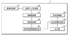
- the image processing apparatus 1 includes an image acquiring unit 11, a depth map generating unit 12, an area recognizing unit 13, a boundary detecting unit 14, a candidate area of interest extracting unit 15, an area of interest determining unit 16, an output unit 17, and a shape grasping unit. 18 functions are exhibited.
- the image acquisition unit 11 acquires images from the camera 2 .
- the depth map generator 12 uses the image acquired from the camera 2 to generate depth map information.
- the region recognizing unit 13 recognizes to which of a plurality of designated different region classes related to an object captured in the captured image each pixel of the acquired captured image belongs.
- a boundary detection unit 14 detects the boundary of each area recognized in photographing.
- the candidate area-of-interest extraction unit 15 identifies, as a candidate area of interest, a class-unrecognized area that does not belong to any of the plurality of area classes in areas in the captured image that indicate a predetermined area class among the plurality of different area classes.
- the region-of-interest determination unit 16 determines whether the candidate region of interest is a desired region of interest.
- the output unit 17 outputs the region of interest.
- the shape grasping unit 18 detects the shape of the road based on the steering angle and the like obtained from the CAN information and the like.
- the region-of-interest determining unit 16 determines whether the candidate region of interest indicates a three-dimensional object based on the depth information indicated by each pixel of the candidate region of interest, and when the candidate region of interest indicates a three-dimensional object, The target candidate area is determined to be the target area.
- the region-of-interest determining unit 16 determines whether the candidate region of interest indicates a stationary object based on the change in depth information indicated by each pixel of the candidate region of interest.
- the region may be determined as the region of interest.
- the area recognition unit 13 recognizes to which of a plurality of designated different area classes related to the object appearing in the captured image each pixel of the captured image including the road and the moving object such as the vehicle 20 traveling on the road belongs. You can At this time, the candidate area-of-interest extracting unit 15 specifies, as a candidate area of interest, a class-unrecognized area at least partially adjacent to an area in the photographed image belonging to a road class indicating a road area among a plurality of area classes. good.
- the region-of-interest determining unit 16 may determine the region of interest from among the candidate regions of interest in the plurality of region classes, excluding the region in the captured image belonging to the moving object.
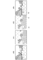
- FIG. 4 is a diagram showing an outline of processing of the image processing apparatus.
- FIG. 4 shows a photographed image (40), a processing result (41) of the region recognition unit 13 using the photographed image, a processing result (42) of the boundary detection unit 14 and the target candidate region extraction unit 15, and a target A processing result (43) of the area determination unit 16 is shown.
- the processing result (42) of the boundary detection unit 14 and the target candidate area extraction unit 15 includes the information B indicating the boundary and the pixel information indicating the target candidate area A1.
- the processing result (43) of the region-of-interest determination unit 16 includes information on pixels indicating the region of interest A2.
- FIG. 5 is a diagram showing the processing flow of the image processing apparatus.
- the processing flow of the image processing apparatus 1 will be described step by step below.
- the camera 2 outputs a photographed image generated by photographing to the image processing device 1 .
- the image acquisition unit 11 of the image processing device 1 acquires the captured image and outputs it to the depth map generation unit 12 .
- the depth map generator 12 generates depth map information based on the captured image (step S101). Note that the image acquisition unit 11 may acquire depth map information generated by the camera 2 in advance. In this case, the depth map generator 12 may not be provided in the image processing device 1 .
- the depth map information is arrangement information of the distance to the subject included in each pixel of each captured image. Depth map information may be generated by a known technique.
- the depth map generation unit 12 outputs the depth map information to the boundary detection unit 14 and the region-of-interest determination unit 16 .
- the area recognition unit 13 acquires the captured image (40).
- the area recognizing unit 13 recognizes the subject in the captured image for each area class such as sky, wall, road, moving body (traffic participant), and person (step S102).
- a known technique may be used as the technique for the area recognition unit 13 to recognize each pixel of the captured image for each area class indicating a plurality of different objects.
- the area recognition unit 13 calculates the probability that each pixel of the captured image belongs to each area class.
- the area recognition unit 13 generates area recognition information that holds information on the probability that each pixel belongs to the class of each area.
- the area recognition information is arrangement information of probability information for each area class for each pixel of the captured image.
- the area recognition unit 13 outputs the area recognition information, which is the processing result (41), to the boundary detection unit 14.
- the region recognition unit 13 receives a captured image as an input and uses a region class calculation model that outputs the probability that each pixel in the captured image belongs to a plurality of predetermined region classes. can be calculated.
- the area class calculation model may be, for example, a model obtained by machine-learning the relationship between a large number of images as input, information indicating the area class of each pixel of the images as correct data, and the relationship therebetween.
- the region recognition unit 13 acquires the steering angle from the CAN information acquired from the shape recognition unit 18, estimates the curve of the road according to the steering angle based on the information, and recognizes the shape of the road from the estimation result.
- the region recognition unit 13 recognizes that the depth map information indicates that the back left corner is turning leftward, and uses the color and luminance in the image as well as the information indicating the turning leftward to calculate the probability of the road class pixel. may be multiplied by a correction factor so that the left side of the center in the image is higher to increase the probability of road class pixels.
- the boundary detection unit 14 acquires area recognition information.
- the boundary detection unit 14 identifies a pixel having a different region class from adjacent pixels based on the probability of the region class corresponding to each pixel of the captured image included in the region recognition information, and holds a boundary flag for that pixel.
- Boundary information is generated (step S103).
- the boundary information is arrangement information of information indicating whether or not the area class of each pixel is a boundary with another area class.
- the boundary detection unit 14 outputs depth map information, region recognition information, and boundary information to the target candidate region extraction unit 15 .
- the candidate area-of-interest extraction unit 15 acquires the captured image, depth map information, area recognition information, and boundary information.
- the candidate area-of-interest extraction unit 15 uses the area recognition information to determine whether an area in the captured image indicating a specified predetermined area class among a plurality of different area classes does not belong to any of the plurality of area classes.
- a class-unrecognized area is identified as a target candidate area (step S104). For example, when a plurality of area classes are area classes such as sky, wall, road, moving object (traffic participant), and person, the candidate area-of-interest extraction unit 15 extracts a specified area class.
- the target candidate region extraction unit 15 identifies the class unrecognized region as the target candidate region.
- the target candidate region extracting unit 15 determines, as a target candidate region, a class-unrecognized region at least partially adjacent to a region in the photographed image belonging to a road class indicating a road region among the specified region classes, and extracts the target candidate region.
- a candidate area may be identified as a target candidate.
- a class-unrecognized area that is at least partially adjacent to an area in the captured image that belongs to a road class indicating a road area among the specified area classes is an area that straddles the boundary between the road class and another class.
- the candidate region-of-interest extraction unit 15 may determine such a region as a class-unrecognized region.
- the candidate region of interest extraction unit 15 After identifying the class-unrecognized region as the candidate region of interest, the candidate region of interest extraction unit 15 generates candidate region of interest information indicating the arrangement information of pixels indicating the candidate region of interest.
- the candidate area-of-interest extraction unit 15 outputs the captured image, the depth map information, the area recognition information, the boundary information, and the candidate area of interest information to the area-of-interest determination unit 16 .
- the region-of-interest determination unit 16 acquires the captured image, depth map information, region recognition information, boundary information, and candidate region-of-interest information.
- the region-of-interest determination unit 16 identifies a region of interest from the candidate regions of interest indicated by the candidate-of-interest region information (step S105). Specifically, the region-of-interest determination unit 16 acquires depth information indicated by each pixel of the candidate region of interest from the depth map information, and determines whether the candidate region of interest indicates a three-dimensional object based on the depth information. do. When determining that the candidate region of interest indicates a three-dimensional object, the region-of-interest determination unit 16 determines that the candidate region of interest is the region of interest.
- the region of interest determination unit 16 determines that the region is a three-dimensional object because these regions form a surface. Then, the target candidate area is determined as the target area.
- the fact that the depth information is uniform in the vertical and horizontal directions means, for example, that an error in the depth information of each adjacent pixel with respect to a certain pixel as a reference is a predetermined value compared with the depth information of the reference pixel. is less than the value.
- the region-of-interest determination unit 16 determines that the area including these pixels is not a horizontal plane but a three-dimensional object, the area may be determined as the target area. For example, the region-of-interest determination unit 16 may determine that a three-dimensional object is present in the region of interest when the difference in depth information between a reference pixel and an adjacent pixel is such that the difference indicates a continuous plane. .
- the region-of-interest determining unit 16 determines whether the candidate region of interest indicates a stationary object based on the change in depth information indicated by each pixel of the candidate region of interest.
- the region may be determined as the region of interest.
- the region-of-interest determination unit 16 calculates a change in the distance of the candidate region of interest in a predetermined period from a change in depth information of the region.
- the region-of-interest determining unit 16 also calculates changes in the distance of pixels in the region determined as the moving object in the same period from changes in the depth information of the region.
- the region-of-interest determination unit 16 determines that the difference between the change in the absolute value of the change in the distance of the target candidate region in a predetermined period and the change in the absolute value of the change in the distance of pixels in the same period in the region determined as the moving object is a predetermined value. If it is equal to or greater than the change threshold, it is determined that the target candidate area is a stationary object. When the camera 2 of the moving object is used as a reference, the distance of other moving objects running at the same speed as the moving object equipped with the camera 2 does not change greatly, and the distance of the stationary object changes greatly.
- the candidate area of interest can be determined to be a stationary object.
- the target region determining unit 16 may determine the target candidate region to be the target region.
- the region-of-interest determining unit 16 may determine the candidate region of interest as the region of interest when determining that the candidate region of interest is a stationary object even when the candidate region of interest is not determined to be a three-dimensional object.
- the region-of-interest determining unit 16 may determine a candidate region of interest in a region excluding a region in a captured image belonging to a class including a moving body as a region of interest.
- An area belonging to the class including the moving object is an area in which the probability of the class included in the value in the area recognition information corresponding to each pixel of the captured image is equal to or greater than a predetermined probability.
- the region-of-interest determination unit 16 may determine the region of interest from candidate regions of interest excluding regions recognized as regions of a class including such a moving object.
- the region-of-interest determining unit 16 acquires the steering angle from the CAN information acquired from the shape grasping unit 18, estimates the curve of the road according to the steering angle based on the information, and recognizes the shape of the road from the estimation result.
- the recognition result of the region recognition unit 13 may be corrected by doing so. For example, if the steering angle is 15 degrees to the left, the road is turning left.
- the region recognition unit 13 recognizes that the depth map information indicates that the back left corner is turning leftward, and uses the color and luminance in the image as well as the information indicating the turning leftward to calculate the probability of the road class pixel. may be multiplied by a correction factor so that the left side of the center in the image is higher to increase the probability of road class pixels.
- the region-of-interest determining unit 16 may determine the region of interest from among the candidate regions of interest using region recognition information obtained by correcting the recognition result of the region recognizing unit 13 .
- the region-of-interest determination unit 16 may determine the region of interest from among the candidate regions of interest, but does not have to immediately output the region as the region of interest. For example, the region-of-interest determination unit 16 uses a plurality of captured images to determine regions of interest with little positional deviation, such as a threshold value or less, to be the same region of interest. If the region of interest is included, the region may be determined as the region of interest. For example, if the same region of interest is included in a predetermined number of consecutive captured images, it may be determined to output that region of interest. The region-of-interest determining unit 16 may determine that the candidate region of interest is the region of interest when the size of the candidate region of interest is equal to or greater than a predetermined size.
- the region-of-interest determining unit 16 After identifying the region of interest, the region-of-interest determining unit 16 generates region-of-interest information indicating arrangement information of pixels indicating the region of interest. The region-of-interest determination unit 16 outputs the region-of-interest information to the output unit 17 .
- the output unit 17 outputs the captured image and the region-of-interest information to a predetermined device (step S106). For example, if the region of interest does not belong to any of a plurality of region classes designated in advance, there is a high possibility that the region of interest is an obstacle. Therefore, for example, if the output destination is an automatic driving processing device, it is possible to recognize an obstacle and control the stopping operation of the vehicle 20 .
- the image processing device 1 determines the region of interest.
- the image processing device 1 may transmit the image acquired from the camera 2 to the server device 3, and the server device 3 may determine the region of interest from the acquired image in the same manner as the above-described processing.
- the server device 3 performs only a part of the above-described processing, the server device 3 transmits the result to the image processing device 1, and the image processing device 1 performs the subsequent processing in the same manner as the above-described processing to obtain the region of interest. may be determined.
- the image processing apparatus 1 may determine an image area such as an obstacle in a photographed image of the front of a moving moving object captured by a camera 2 provided on a moving moving object such as an aircraft. Also, the image processing apparatus 1 may similarly determine a desired region of interest in a desired image.
- FIG. 6 is a diagram showing the minimum configuration of the image processing apparatus.
- FIG. 7 is a diagram showing the processing flow of the image processing apparatus with the minimum configuration.
- the image processing apparatus 1 includes at least a target candidate area specifying unit 61 and a target area determination unit 62 .
- the candidate area-of-interest identifying means 61 identifies, as a candidate area of interest, a class-unrecognized area that does not belong to any of the plurality of area classes in an area in the captured image that indicates a predetermined area class among a plurality of different area classes (step S701).
- the region-of-interest determining means 62 determines whether the candidate region of interest is a desired region of interest (step S702).
- Each of the devices mentioned above has a computer system inside.
- Each process described above is stored in a computer-readable recording medium in the form of a program, and the above process is performed by reading and executing this program by a computer.
- the computer-readable recording medium refers to magnetic disks, magneto-optical disks, CD-ROMs, DVD-ROMs, semiconductor memories, and the like.
- the computer program may be distributed to a computer via a communication line, and the computer receiving the distribution may execute the program.
- the above program may be for realizing part of the functions described above. Further, it may be a so-called difference file (difference program) that can realize the above-described functions in combination with a program already recorded in the computer system.
- difference file difference program
- Reference Signs List 1 image processing device 2 camera 3 server device 11 image acquisition unit 12 depth map generation unit 13 region recognition unit 14 boundary detection unit 15 - Candidate-of-interest region extraction unit (candidate-of-interest region specifying means) 16 ... Region-of-interest determination unit (region-of-interest determination means) 17... Output unit 18... Shape grasping unit
Landscapes
- Engineering & Computer Science (AREA)
- Theoretical Computer Science (AREA)
- Physics & Mathematics (AREA)
- General Physics & Mathematics (AREA)
- Multimedia (AREA)
- Computer Vision & Pattern Recognition (AREA)
- Health & Medical Sciences (AREA)
- Artificial Intelligence (AREA)
- Computing Systems (AREA)
- Databases & Information Systems (AREA)
- Evolutionary Computation (AREA)
- General Health & Medical Sciences (AREA)
- Medical Informatics (AREA)
- Software Systems (AREA)
- Computational Linguistics (AREA)
- Image Processing (AREA)
- Image Analysis (AREA)
- Traffic Control Systems (AREA)
Abstract
Description
図1は本実施形態による画像処理装置を含む画像処理システムの概要を示す図である。
図1で示すように画像処理システム100は、車両20に搭載された画像処理装置1とカメラ2とが、無線通信ネットワークや有線通信ネットワークを介して接続されることにより構成される。画像処理システム100にはサーバ装置3が含まれてよい。サーバ装置3は、画像処理装置1やカメラ2と通信接続してよい。カメラ2は本実施形態においては、道路と当該道路を走行する車両を含む画像を撮影する。カメラ2は画像を画像処理装置1へ出力する。画像処理装置1はカメラ2から取得した画像を用いて、所定の物体が含まれる可能性のある着目候補領域を特定し、その着目候補領域から所定の物体などを示すと思われる着目領域を特定する。本実施形態において画像処理装置1は、道路に落ちている障害物の写る画像内領域を着目領域と特定する。画像から障害物を着目領域と特定することにより、自動運転などにおける障害物を避けるための処理などに利用することができる。
この図が示すように画像処理装置1は、CPU(Central Processing Unit)101、ROM(Read Only Memory)102、RAM(Random Access Memory)103、HDD(Hard Disk Drive)104、通信モジュール105、データベース106等の各ハードウェアを備えたコンピュータである。なおサーバ装置3も同様の構成を備える。
画像処理装置1は車両20の始動に基づいて電源が投入されると起動し、予め記憶する画像処理プログラムを実行する。これにより画像処理装置1には、画像取得部11、深度マップ生成部12、領域認識部13、境界検出部14、着目候補領域抽出部15、着目領域判定部16、出力部17、形状把握部18の各機能を発揮する。
深度マップ生成部12は、カメラ2から取得した画像を用いて深度マップ情報を生成する。
領域認識部13は、取得した撮影画像の各画素が、当該撮影画像に写る対象物に関する指定された複数の異なる領域クラスの何れに属するかを認識する。
境界検出部14は、撮影において認識した各領域の境界を検出する。
着目候補領域抽出部15は、複数の異なる領域クラスのうちの所定の領域クラスを示す撮影画像中の領域において複数の領域クラスの何れにも属さないクラス未認識領域を着目候補領域と特定する。
着目領域判定部16は、着目候補領域が所望の着目領域であるかを判定する。
出力部17は着目領域を出力する。
形状把握部18はCAN情報などから得られたステアリング角度などに基づいて道路の形状を検出する。
図4には、撮影画像(40)と、その撮影画像を用いた領域認識部13の処理結果(41)と、境界検出部14と着目候補領域抽出部15の処理結果(42)と、着目領域判定部16の処理結果(43)を示す。境界検出部14と着目候補領域抽出部15の処理結果(42)には、境界を示す情報Bと着目候補領域A1を示す画素の情報が含まれる。さらに、着目領域判定部16の処理結果(43)には着目領域A2を示す画素の情報が含まれる。
以下、画像処理装置1の処理フローについて順を追って説明する。
車両20が走行中、カメラ2は撮影により生成した撮影画像を画像処理装置1へ出力する。画像処理装置1の画像取得部11は撮影画像を取得して深度マップ生成部12へ出力する。深度マップ生成部12は、取得した撮影画像に基づいて深度マップ情報を生成する(ステップS101)。なお画像取得部11は、予めカメラ2が生成した深度マップ情報を取得してよい。この場合、画像処理装置1に深度マップ生成部12は設けなくてもよい。深度マップ情報は、各撮影画像の各画素に含まれる被写体までの距離の配列情報である。深度マップ情報の生成は公知の技術により行われてよい。深度マップ生成部12は深度マップ情報を、境界検出部14、着目領域判定部16へ出力する。
図7は最小構成の画像処理装置の処理フローを示す図である。
画像処理装置1は、少なくとも着目候補領域特定手段61、着目領域判定手段62と、を備える。
着目候補領域特定手段61は、複数の異なる領域クラスのうちの所定の領域クラスを示す撮影画像中の領域において複数の領域クラスの何れにも属さないクラス未認識領域を着目候補領域と特定する(ステップS701)。
着目領域判定手段62は、着目候補領域が所望の着目領域であるかを判定する(ステップS702)。
2・・・カメラ
3・・・サーバ装置
11・・・画像取得部
12・・・深度マップ生成部
13・・・領域認識部
14・・・境界検出部
15・・・着目候補領域抽出部(着目候補領域特定手段)
16・・・着目領域判定部(着目領域判定手段)
17・・・出力部
18・・・形状把握部
Claims (7)
- 取得した撮影画像の各画素が、当該撮影画像に写る対象物に関する指定された複数の異なる領域クラスの何れに属するかを認識する領域認識手段と、
前記複数の異なる領域クラスのうちの所定の領域クラスを示す前記撮影画像中の領域において前記複数の領域クラスの何れにも属さないクラス未認識領域を着目候補領域と特定する着目候補領域特定手段と、
前記着目候補領域が所定の所望領域であるかを判定する着目領域判定手段と、
を備える画像処理装置。 - 前記着目領域判定手段は、前記着目候補領域の各画素が示す深度情報に基づいて当該着目候補領域が立体物を示すかを判定し、当該着目候補領域が立体物を示す時に、当該着目候補領域を前記着目領域と判定する
請求項1に記載の画像処理装置。 - 前記着目領域判定手段は、前記着目候補領域の各画素が示す深度情報の変化に基づいて当該着目候補領域が静止物を示すかを判定し、当該着目候補領域が静止物を示す時に、当該着目候補領域を前記着目領域と判定する
請求項1または請求項2に記載の画像処理装置。 - 前記領域認識手段は、道路と当該道路を走行する移動体を含む前記撮影画像の各画素が、前記撮影画像に写る対象物に関する指定された複数の異なる領域クラスの何れに属するかを認識し、
前記着目候補領域特定手段は、前記複数の領域クラスのうち道路の領域を示す道路クラスに属する前記撮影画像中の領域に少なくとも一部が隣接する前記クラス未認識領域を前記着目候補領域と特定する
請求項1から請求項3の何れか一項に記載の画像処理装置。 - 前記着目領域判定手段は、前記複数の領域クラスのうち移動体に属する前記撮影画像中の領域を除く領域における前記着目候補領域の中から前記着目領域を判定する
請求項1から請求項4の何れか一項に記載の画像処理装置。 - 取得した撮影画像の各画素が、当該撮影画像に写る対象物に関する指定された複数の異なる領域クラスの何れに属するかを認識し、
前記複数の異なる領域クラスのうちの所定の領域クラスを示す前記撮影画像中の領域において前記複数の領域クラスの何れにも属さないクラス未認識領域を着目候補領域と特定し、
前記着目候補領域が所定の所望領域であるかを判定する
画像処理方法。 - 画像処理装置のコンピュータを、
取得した撮影画像の各画素が、当該撮影画像に写る対象物に関する指定された複数の異なる領域クラスの何れに属するかを認識する領域認識手段、
前記複数の異なる領域クラスのうちの所定の領域クラスを示す前記撮影画像中の領域において前記複数の領域クラスの何れにも属さないクラス未認識領域を着目候補領域と特定する着目候補領域特定手段、
前記着目候補領域が所定の所望領域であるかを判定する着目領域判定手段、
として機能させるプログラム。
Priority Applications (4)
| Application Number | Priority Date | Filing Date | Title |
|---|---|---|---|
| EP21934837.2A EP4258243A4 (en) | 2021-03-30 | 2021-03-30 | IMAGE PROCESSING DEVICE, IMAGE PROCESSING METHOD AND PROGRAM |
| US18/270,674 US20240062505A1 (en) | 2021-03-30 | 2021-03-30 | Image processing device, image processing method, and program |
| JP2023509971A JPWO2022208666A1 (ja) | 2021-03-30 | 2021-03-30 | |
| PCT/JP2021/013595 WO2022208666A1 (ja) | 2021-03-30 | 2021-03-30 | 画像処理装置、画像処理方法、プログラム |
Applications Claiming Priority (1)
| Application Number | Priority Date | Filing Date | Title |
|---|---|---|---|
| PCT/JP2021/013595 WO2022208666A1 (ja) | 2021-03-30 | 2021-03-30 | 画像処理装置、画像処理方法、プログラム |
Publications (1)
| Publication Number | Publication Date |
|---|---|
| WO2022208666A1 true WO2022208666A1 (ja) | 2022-10-06 |
Family
ID=83455798
Family Applications (1)
| Application Number | Title | Priority Date | Filing Date |
|---|---|---|---|
| PCT/JP2021/013595 WO2022208666A1 (ja) | 2021-03-30 | 2021-03-30 | 画像処理装置、画像処理方法、プログラム |
Country Status (4)
| Country | Link |
|---|---|
| US (1) | US20240062505A1 (ja) |
| EP (1) | EP4258243A4 (ja) |
| JP (1) | JPWO2022208666A1 (ja) |
| WO (1) | WO2022208666A1 (ja) |
Citations (5)
| Publication number | Priority date | Publication date | Assignee | Title |
|---|---|---|---|---|
| JP2003030776A (ja) * | 2001-07-17 | 2003-01-31 | Japan Radio Co Ltd | 物体検知システムおよびその方法 |
| JP2004326270A (ja) * | 2003-04-22 | 2004-11-18 | Koito Ind Ltd | 路上落下物検出装置 |
| JP2008529183A (ja) | 2005-02-04 | 2008-07-31 | フィコ ミラーズ,エスエー | 自動車の前方にある障害物を検知するシステム |
| JP2016062356A (ja) * | 2014-09-18 | 2016-04-25 | トヨタ自動車株式会社 | 立体物検出装置 |
| JP2016224797A (ja) | 2015-06-02 | 2016-12-28 | 株式会社デンソー | 落下物検出装置 |
Family Cites Families (1)
| Publication number | Priority date | Publication date | Assignee | Title |
|---|---|---|---|---|
| WO2020031812A1 (ja) * | 2018-08-09 | 2020-02-13 | ソニー株式会社 | 情報処理装置、情報処理方法、情報処理プログラム、及び移動体 |
-
2021
- 2021-03-30 US US18/270,674 patent/US20240062505A1/en active Pending
- 2021-03-30 WO PCT/JP2021/013595 patent/WO2022208666A1/ja active Application Filing
- 2021-03-30 JP JP2023509971A patent/JPWO2022208666A1/ja active Pending
- 2021-03-30 EP EP21934837.2A patent/EP4258243A4/en active Pending
Patent Citations (5)
| Publication number | Priority date | Publication date | Assignee | Title |
|---|---|---|---|---|
| JP2003030776A (ja) * | 2001-07-17 | 2003-01-31 | Japan Radio Co Ltd | 物体検知システムおよびその方法 |
| JP2004326270A (ja) * | 2003-04-22 | 2004-11-18 | Koito Ind Ltd | 路上落下物検出装置 |
| JP2008529183A (ja) | 2005-02-04 | 2008-07-31 | フィコ ミラーズ,エスエー | 自動車の前方にある障害物を検知するシステム |
| JP2016062356A (ja) * | 2014-09-18 | 2016-04-25 | トヨタ自動車株式会社 | 立体物検出装置 |
| JP2016224797A (ja) | 2015-06-02 | 2016-12-28 | 株式会社デンソー | 落下物検出装置 |
Non-Patent Citations (1)
| Title |
|---|
| See also references of EP4258243A4 |
Also Published As
| Publication number | Publication date |
|---|---|
| EP4258243A1 (en) | 2023-10-11 |
| US20240062505A1 (en) | 2024-02-22 |
| EP4258243A4 (en) | 2024-01-03 |
| JPWO2022208666A1 (ja) | 2022-10-06 |
Similar Documents
| Publication | Publication Date | Title |
|---|---|---|
| US10885398B2 (en) | Joint 3D object detection and orientation estimation via multimodal fusion | |
| JP5926228B2 (ja) | 自律車両用の奥行き検知方法及びシステム | |
| JP5870273B2 (ja) | 物体検出装置、物体検出方法及びプログラム | |
| JP5663352B2 (ja) | 画像処理装置、画像処理方法、及び画像処理プログラム | |
| JP7135665B2 (ja) | 車両制御システム、車両の制御方法及びコンピュータプログラム | |
| US10803605B2 (en) | Vehicle exterior environment recognition apparatus | |
| US20180336701A1 (en) | Image processing device, object recognizing device, device control system, moving object, image processing method, and computer-readable medium | |
| Kowsari et al. | Real-time vehicle detection and tracking using stereo vision and multi-view AdaBoost | |
| EP3115933B1 (en) | Image processing device, image capturing device, mobile body control system, image processing method, and computer-readable recording medium | |
| JP2014137815A (ja) | 歪みのあるカメラ画像を補正するシステム及び方法 | |
| US20200074212A1 (en) | Information processing device, imaging device, equipment control system, mobile object, information processing method, and computer-readable recording medium | |
| WO2020154990A1 (zh) | 目标物体运动状态检测方法、设备及存储介质 | |
| KR102013781B1 (ko) | 다른 초점 거리를 갖는 두 개의 카메라를 이용한 객체 검출 방법 및 그 장치 | |
| US20210326612A1 (en) | Vehicle detection method and device | |
| JPWO2017134936A1 (ja) | 物体検出装置、機器制御システム、撮像装置、物体検出方法、及びプログラム | |
| Gu et al. | Histograms of the normalized inverse depth and line scanning for urban road detection | |
| JP2020061140A (ja) | ブラインドスポットモニタリングのためのcnnの学習方法、テスティング方法、学習装置、及びテスティング装置 | |
| KR102372296B1 (ko) | 영상 기반 주행 차로 판단 장치 및 방법 | |
| Geiger et al. | Object flow: A descriptor for classifying traffic motion | |
| Dornaika et al. | A new framework for stereo sensor pose through road segmentation and registration | |
| JP2004038624A (ja) | 車両認識方法、車両認識装置及び車両認識用プログラム | |
| JP2018073275A (ja) | 画像認識装置 | |
| JP2020077293A (ja) | 区画線検出装置及び区画線検出方法 | |
| Kim et al. | MOD: Multi-camera based local position estimation for moving objects detection | |
| US10810757B2 (en) | Vehicle exterior environment recognition apparatus |
Legal Events
| Date | Code | Title | Description |
|---|---|---|---|
| 121 | Ep: the epo has been informed by wipo that ep was designated in this application |
Ref document number: 21934837 Country of ref document: EP Kind code of ref document: A1 |
|
| WWE | Wipo information: entry into national phase |
Ref document number: 18270674 Country of ref document: US |
|
| ENP | Entry into the national phase |
Ref document number: 2021934837 Country of ref document: EP Effective date: 20230704 |
|
| WWE | Wipo information: entry into national phase |
Ref document number: 2023509971 Country of ref document: JP |
|
| NENP | Non-entry into the national phase |
Ref country code: DE |