WO2021181663A1 - 超臨界流体発電システム - Google Patents
超臨界流体発電システム Download PDFInfo
- Publication number
- WO2021181663A1 WO2021181663A1 PCT/JP2020/011142 JP2020011142W WO2021181663A1 WO 2021181663 A1 WO2021181663 A1 WO 2021181663A1 JP 2020011142 W JP2020011142 W JP 2020011142W WO 2021181663 A1 WO2021181663 A1 WO 2021181663A1
- Authority
- WO
- WIPO (PCT)
- Prior art keywords
- heat
- supercritical fluid
- power generation
- heat exchanger
- fluid power
- Prior art date
- Legal status (The legal status is an assumption and is not a legal conclusion. Google has not performed a legal analysis and makes no representation as to the accuracy of the status listed.)
- Ceased
Links
Images
Classifications
-
- F—MECHANICAL ENGINEERING; LIGHTING; HEATING; WEAPONS; BLASTING
- F01—MACHINES OR ENGINES IN GENERAL; ENGINE PLANTS IN GENERAL; STEAM ENGINES
- F01K—STEAM ENGINE PLANTS; STEAM ACCUMULATORS; ENGINE PLANTS NOT OTHERWISE PROVIDED FOR; ENGINES USING SPECIAL WORKING FLUIDS OR CYCLES
- F01K25/00—Plants or engines characterised by use of special working fluids, not otherwise provided for; Plants operating in closed cycles and not otherwise provided for
- F01K25/08—Plants or engines characterised by use of special working fluids, not otherwise provided for; Plants operating in closed cycles and not otherwise provided for using special vapours
- F01K25/10—Plants or engines characterised by use of special working fluids, not otherwise provided for; Plants operating in closed cycles and not otherwise provided for using special vapours the vapours being cold, e.g. ammonia, carbon dioxide, ether
-
- F—MECHANICAL ENGINEERING; LIGHTING; HEATING; WEAPONS; BLASTING
- F01—MACHINES OR ENGINES IN GENERAL; ENGINE PLANTS IN GENERAL; STEAM ENGINES
- F01K—STEAM ENGINE PLANTS; STEAM ACCUMULATORS; ENGINE PLANTS NOT OTHERWISE PROVIDED FOR; ENGINES USING SPECIAL WORKING FLUIDS OR CYCLES
- F01K7/00—Steam engine plants characterised by the use of specific types of engine; Plants or engines characterised by their use of special steam systems, cycles or processes; Control means specially adapted for such systems, cycles or processes; Use of withdrawn or exhaust steam for feed-water heating
- F01K7/32—Steam engine plants characterised by the use of specific types of engine; Plants or engines characterised by their use of special steam systems, cycles or processes; Control means specially adapted for such systems, cycles or processes; Use of withdrawn or exhaust steam for feed-water heating the engines using steam of critical or overcritical pressure
Definitions
- the present invention relates to a supercritical fluid power generation system that uses a supercritical fluid as a working fluid.
- the present invention has been made in view of this point, and one of the objects of the present invention is to provide a supercritical fluid power generation system capable of achieving both high efficiency of the system and suppression of increase in equipment cost.
- One aspect of the supercritical fluid power generation system of the present invention includes a heat source and a supercritical fluid power generation unit using a closed cycle in which a supercritical fluid is used as a working fluid, including a turbine, a cooler, and a compression device. It further includes an intermediate heat medium circulation unit that circulates a liquid heat medium heated by a high temperature gas heated by a heat source, and the intermediate heat medium circulation unit exchanges heat between the high temperature gas and the heat medium. It is characterized by including a heat recovery heat exchanger and an intermediate heat exchanger that exchanges heat between the heat medium and the supercritical fluid.
- the heat of the heat source can be transferred to the supercritical fluid of the supercritical fluid power generation section through the liquid heat medium of the intermediate heat medium circulation section.
- the heat recovery heat exchanger of the intermediate heat medium circulation part does not use a supercritical fluid, in other words, it is not necessary to use an expensive material for corrosion countermeasures, so that it is possible to suppress an increase in equipment cost. can.
- the intermediate heat exchanger since the heat medium becomes liquid and exchanges heat with the supercritical fluid, the heat transfer area between them can be reduced.
- the amount of expensive materials used in the intermediate heat exchanger can be reduced, and even in a configuration in which the intermediate heat exchanger and the heat recovery heat exchanger are combined, heat is recovered from the high temperature gas of the heat medium with a supercritical fluid. It is possible to suppress an increase in equipment cost as compared with. Moreover, while suppressing the increase in equipment cost, the heat transfer area of the heat recovery heat exchanger can be increased to raise the temperature of the heat medium and thus the supercritical fluid flowing through the intermediate heat exchanger, so that the supercritical fluid power generation unit can raise the temperature. High efficiency can be achieved. As described above, in the present invention, it is possible to suppress the increase in equipment cost and to improve the efficiency of the system in which the supercritical fluid is heated to a high temperature.
- the supercritical fluid power generation system according to the present invention is not limited to the following embodiments, and can be variously modified and implemented within the scope of the purpose.
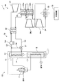
- FIG. 1 is a schematic configuration diagram of a supercritical fluid power generation system according to an embodiment.
- the supercritical fluid power generation system 1 includes a boiler facility 10 having a heat source 11, a supercritical fluid power generation unit 30, an intermediate heat medium circulation unit 50, and a control device 70.
- the supercritical fluid power generation system 1 uses a closed cycle in which the working fluid is a supercritical fluid, specifically, supercritical carbon dioxide (CO 2).
- CO 2 supercritical carbon dioxide
- the boiler equipment 10 burns fuel such as biomass or fossil fuel to serve as a heat source 11, and air is supplied to the heat source 11 via an air heater 12.
- the boiler equipment 10 generates a high-temperature gas (combustion gas) 13 whose temperature has been raised by the heat source 11, and the high-temperature gas 13 is discharged to the outside of the system 1 via the flow path 14.
- the flow path 14 is provided with an air heater 12 and a heat recovery heat exchanger 51, which will be described later, of an intermediate heat medium circulation unit 50 on the upstream side of the air heater 12.
- the air heater 12 is configured as a regenerative heat exchanger that exchanges heat between the high temperature gas 13 heated by the heat source 11 and the air supplied to the heat source 11.
- the heat source 11 is not particularly limited, and various well-known heat sources such as geothermal heat, solar heat, and biomass can be used in addition to thermal power and nuclear power.
- the supercritical fluid power generation unit 30 uses a closed cycle in which the working fluid is a supercritical fluid, specifically, supercritical carbon dioxide (CO 2).
- the supercritical fluid power generation unit 30 includes a turbine 31, a regenerative heat exchanger 32, a cooler 33, and a compression device 34.
- supercritical carbon dioxide heated by the intermediate heat exchanger 52 described later in the intermediate heat medium circulation unit 50 flows in, and while passing through, the supercritical carbon dioxide is expanded to generate mechanical power.
- the turbine 31 can, for example, rotate a drive shaft to drive a generator (none of which is shown), and the generator can generate electricity.
- the supercritical carbon dioxide that has been expanded and worked in the turbine 31 flows out to the regenerated heat exchanger 32.
- the regenerated heat exchanger 32 exchanges heat between the high-temperature supercritical carbon dioxide that flows out to the cooler 33 side via the turbine 31 and the low-temperature supercritical carbon dioxide that has passed through the cooler 33 and the compressor 34. By such heat exchange, the regenerative heat exchanger 32 cools the supercritical carbon dioxide flowing from the turbine 31 to the cooler 33, and heats the supercritical carbon dioxide after passing through the compression device 34.
- the regenerative heat exchanger 32 includes a high-temperature regenerative heat exchanger 32a and a low-temperature regenerative heat exchanger 32b, and performs heat exchange in two stages. The supercritical carbon dioxide heat exchanged by the regenerative heat exchanger 32 flows out to the cooler 33.
- the cooler 33 cools the supercritical carbon dioxide flowing in through the regenerated heat exchanger 32 by the outside air.
- the supercritical carbon dioxide cooled by the cooler 33 flows out to the compression device 34.
- the compression device 34 compresses the supercritical carbon dioxide expanded by the turbine 31 via a predetermined driving force while the supercritical carbon dioxide flows in and passes therethrough.
- the compressor 34 includes a main compressor 34a and a bypass compressor 34b.
- the main compressor 34a compresses supercritical carbon dioxide that has been expanded by the turbine 31 and then cooled through the regenerative heat exchanger 32 and the cooler 33.
- the supercritical carbon dioxide compressed by the main compressor 34a flows out to the high temperature regenerative heat exchanger 32a of the regenerated heat exchanger 32.
- the bypass compressor 34b extracts and compresses supercritical carbon dioxide flowing from the low temperature regenerative heat exchanger 32b to the cooler 33.
- the supercritical carbon dioxide compressed by the bypass compressor 34b flows out to the high temperature regenerative heat exchanger 32a of the regenerative heat exchanger 32.
- the supercritical carbon dioxide that has passed through the high-temperature regenerative heat exchanger 32a flows into the intermediate heat exchanger 52 described later in the intermediate heat medium circulation unit 50 and flows into the turbine 31 again. In this way, supercritical carbon dioxide is circulated in the supercritical fluid power generation unit 30.
- the intermediate heat medium circulation unit 50 includes a heat recovery heat exchanger 51 and an intermediate heat exchanger 52 that circulate a liquid heat medium and transfer the heat of the boiler equipment 10 to the supercritical fluid power generation unit 30.
- a chemically inert molten salt hereinafter, simply referred to as “molten salt”
- thermal oil is used in addition to the molten salt.
- the heat recovery heat exchanger 51 exchanges heat between the molten salt passing through the inside and the high temperature gas 13 heated by the heat source 11. Therefore, the molten salt circulated in the intermediate heat medium circulation unit 50 is heated by the high temperature gas 13.
- the intermediate heat exchanger 52 exchanges heat between the molten salt passing through the inside and the supercritical carbon dioxide heated by the regenerated heat exchanger 32. Therefore, the intermediate heat medium circulation unit 50 can recover the heat of the heat source 11 by the heat recovery heat exchanger 51, and transfer the recovered heat to the supercritical fluid power generation unit 30 by the intermediate heat exchanger 52.
- the outlet of the heat recovery heat exchanger 51 and the inlet of the intermediate heat exchanger 52 are connected by a high temperature side flow path 53, and a pump 54 for pumping molten salt is provided in the middle of the high temperature side flow path 53.
- the outlet of the intermediate heat exchanger 52 and the inlet of the heat recovery heat exchanger 51 are connected by a low temperature side flow path 56.
- a three-way valve (adjustment valve) 57 is provided in the middle of the low temperature side flow path 56.
- the three-way valve 57 and the downstream side of the pump 54 in the high temperature side flow path 53 are connected by a bypass flow path 58.
- the bypass flow path 58 connects the upstream side and the downstream side of the intermediate heat exchanger 52, and connects the upstream side and the downstream side of the heat recovery heat exchanger 51.
- the three-way valve 57 switches between the presence / absence of circulation of molten salt in the bypass flow path 58 and the presence / absence of circulation of molten salt in the intermediate heat exchanger 52, and the molten salt passing through the intermediate heat exchanger 52 is the heat recovery heat exchanger 51. It is possible to switch which of the bypass flow path 58 and the bypass flow path 58.
- the molten salt in the three-way valve 57 when the outflow destination of the molten salt in the three-way valve 57 is switched to the heat recovery heat exchanger 51 to drive the pump 54, the molten salt is circulated in the heat recovery heat exchanger 51 and the intermediate heat exchanger 52.
- the molten salt flows through the heat recovery heat exchanger 51 and is heated by the high temperature gas 13 generated in the boiler equipment 10.
- the heated molten salt flows into the intermediate heat exchanger 52 via the high temperature side flow path 53, and transfers heat to the supercritical carbon dioxide circulating in the supercritical fluid power generation unit 30.
- the molten salt that has transferred heat through the intermediate heat exchanger 52 returns to the heat recovery heat exchanger 51 through the low temperature side flow path 56.
- the intermediate heat medium circulation unit 50 since the heat medium is a molten salt, high corrosion resistance in piping or the like is not required. Therefore, an inexpensive carbon steel pipe used in a conventional steam power generation system can be used for each part of the intermediate heat medium circulation part 50 to suppress an increase in equipment cost.
- the heat recovery heat exchanger 51 since heat is exchanged between the high temperature gas that becomes a gas and the molten salt that becomes a liquid, it is necessary to increase the heat transfer area in order to improve the heat recovery efficiency. By using it, it is possible to suppress an increase in cost. In other words, heat recovery can be made highly efficient, and an increase in equipment cost can be suppressed.
- the intermediate heat exchanger 52 heat exchange occurs between the molten salt that becomes a liquid and supercritical carbon dioxide, and since both of them have a high density, the heat recovery efficiency should be maintained well even if the heat transfer area is small. Can be done. Specifically, the heat transfer from the molten salt to the supercritical carbon dioxide is about 10 times higher than that from the case where the heat is transferred from the high temperature gas to the supercritical carbon dioxide.
- the heat transfer part such as the pipe through which supercritical carbon dioxide flows can be made small and compact. Since high-temperature supercritical carbon dioxide flows in such a heat transfer section, it is necessary to use an expensive material having high corrosion resistance. The amount used can be significantly reduced. As a result, the supercritical fluid power generation unit 30 using high-temperature supercritical carbon dioxide can improve the efficiency of power generation and suppress the cost increase for corrosion countermeasures.
- the circulation of the molten salt to the heat recovery heat exchanger 51 can be stopped.
- the molten salt delivered to the intermediate heat exchanger 52 is not heated, and the temperature of the molten salt is lowered, so that the output of the supercritical fluid power generation unit 30 can be lowered.
- the temperature of the molten salt rises and the output of the supercritical fluid power generation unit 30 can be increased.
- the embodiment of the present invention is not limited to the above embodiment, and may be variously modified, replaced, or modified without departing from the spirit of the technical idea of the present invention. Furthermore, if the technical idea of the present invention can be realized in another way by the advancement of technology or another technology derived from it, it may be carried out by using that method. Therefore, the scope of claims covers all embodiments that may be included within the scope of the technical idea of the present invention.
- the regenerative heat exchanger 32 is provided with the two-stage regenerated heat exchangers 32a and 32b, but the present invention is not limited to this, and one of them may be omitted, or the regenerated heat exchanger 32 may be further regenerated. A heat exchanger may be added. Further, the supercritical fluid power generation system 1 may be configured without the regenerated heat exchanger 32 itself. However, since the supercritical fluid power generation system 1 has the regenerated heat exchanger 32, it is advantageous in that the supercritical carbon dioxide introduced into the intermediate heat exchanger 52 can be efficiently heated.
- bypass compressor 34b in the compression device 34 may be omitted.
- the adjusting valve in the intermediate heat medium circulation unit 50 is not limited to the above-mentioned three-way valve 57, and other ones capable of simultaneously adjusting the flow rate of the molten salt to the bypass flow path 58 and the flow rate of the molten salt to the intermediate heat exchanger 52. It may be a configuration or the like.
- the supercritical fluid is not limited to supercritical carbon dioxide as long as the supercritical fluid power generation system 1 can be operated as in each of the above embodiments.
Landscapes
- Engineering & Computer Science (AREA)
- Chemical & Material Sciences (AREA)
- Combustion & Propulsion (AREA)
- Mechanical Engineering (AREA)
- General Engineering & Computer Science (AREA)
- Engine Equipment That Uses Special Cycles (AREA)
Abstract
システムの高効率化と設備コストの上昇抑制とを両立できる超臨界流体発電システムを提供すること。超臨界流体発電システム(1)は、熱源(11)と、タービン(31)、冷却器(33)及び圧縮装置(34)を備えて超臨界二酸化炭素を作動流体とする閉サイクルを用いた超臨界流体発電部(30)と、熱源によって昇温された高温ガス(13)で加熱される液状の溶融塩を循環する中間熱媒循環部(50)とを有している。中間熱媒循環部は、高温ガスと溶融塩との間で熱交換する熱回収熱交換器(51)と、溶融塩と超臨界二酸化炭素との間で熱交換する中間熱交換器(52)とを備えている。
Description
本発明は、超臨界流体を作動流体として用いる超臨界流体発電システムに関する。
火力発電をはじめとする従来の蒸気発電システムに対し、高効率且つコンパクト化が期待される超臨界二酸化炭素発電サイクル(特許文献1参照)が盛んに研究されている。かかる研究において、様々な構成のサイクルが比較され分流再圧サイクルが高効率であるとする研究成果がある。
超臨界流体を用いたシステムでは、超臨界流体を高温とする程、高効率になる一方、超臨界流体、特に超臨界二酸化炭素にあっては高温で腐食性を有する。従って、ボイラ等で高温高圧な蒸気を流す炭素鋼鋼管に高温の超臨界二酸化炭素を流すと腐食する可能性が高くなる。このため、超臨界二酸化炭素をボイラにて高温に加熱して利用する場合、炭素鋼鋼管より高価で耐食性が高い材料を用いる必要があり、腐食対策用に設備コストが上昇する、という問題がある。
また、熱源からの高温ガス(気体)を超臨界二酸化炭素にて十分に熱回収して高効率とするには、ボイラにて高温ガスと接触する熱交換部等の伝熱面積を大きくする必要がある。伝熱面積が大きくなると設備コストが上昇し、特に、高価な材料を用いる超臨界二酸化炭素を用いたシステムでは、設備コストの上昇が顕著になる。従って、高効率化を図る程、設備コストが上昇し、設備コストを安価にしようとするとシステムの効率が低下する。このように、システムの高効率化と設備コストの上昇抑制とはトレードオフの関係にあり、それらを両方とも改善することが超臨界流体を用いることでより困難となっている。
本発明は、かかる点に鑑みてなされたものであり、システムの高効率化と設備コストの上昇抑制とを両立することができる超臨界流体発電システムを提供することを目的の一つとする。
本発明における一態様の超臨界流体発電システムは、熱源と、タービン、冷却器及び圧縮装置を備えて超臨界流体を作動流体とする閉サイクルを用いた超臨界流体発電部とを有し、前記熱源によって昇温された高温ガスで加熱される液状の熱媒を循環する中間熱媒循環部を更に含み、前記中間熱媒循環部は、前記高温ガスと前記熱媒との間で熱交換する熱回収熱交換器と、前記熱媒と前記超臨界流体との間で熱交換する中間熱交換器とを備えていることを特徴とする。
本発明によれば、中間熱媒循環部の液状の熱媒を介して、熱源の熱を超臨界流体発電部の超臨界流体に伝達することができる。かかる伝達において、中間熱媒循環部の熱回収熱交換器は超臨界流体を用いない、言い換えると腐食対策用に高価な材料を用いなくてもよくなるので、設備コストが高くなることを抑えることができる。一方、中間熱交換器では、熱媒が液状となって超臨界流体と熱交換するので、それらの間での伝熱面積を小さくすることができる。これにより、中間熱交換器での高価な材料の使用量を少なくでき、中間熱交換器と熱回収熱交換器とを合わせた構成でも、熱媒の高温ガスから超臨界流体で熱回収する構造に比べて設備コストの上昇を抑制することができる。しかも、かかる設備コストの上昇を抑制しつつ、熱回収熱交換器の伝熱面積を大きくして中間熱交換器に流れる熱媒ひいては超臨界流体の温度を高くでき、超臨界流体発電部での高効率化を図ることができる。このように、本発明においては、設備コストの上昇抑制と、超臨界流体を高温としたシステムの高効率化とを両立することができる。
以下、本発明の一実施の形態に係る超臨界流体発電システムについて、添付の図面を参照しながら詳細に説明する。なお、本発明に係る超臨界流体発電システムについては、以下の実施の形態に限定されるものではなく、その趣旨の範囲内で種々変形して実施することができる。
図1は、実施の形態に係る超臨界流体発電システムの概略構成図である。図1に示すように、超臨界流体発電システム1は、熱源11を有するボイラ設備10と、超臨界流体発電部30と、中間熱媒循環部50と、制御装置70とを備えている。超臨界流体発電システム1は、作動流体を超臨界流体、具体的には、超臨界二酸化炭素(CO2)とする閉サイクルを用いている。
ボイラ設備10は、バイオマスや化石燃料等の燃料を燃焼して熱源11とし、熱源11にはエアヒータ12を介して空気が供給される。ボイラ設備10では熱源11によって昇温された高温ガス(燃焼ガス)13を発生し、該高温ガス13が流路14を経てシステム1の外部に排出される。流路14には、エアヒータ12と、エアヒータ12より上流側に中間熱媒循環部50の後述する熱回収熱交換器51とが設けられている。エアヒータ12は、熱源11で昇温された高温ガス13と、熱源11に供給する空気とで熱交換を行う再生熱交換器として構成される。熱源11は、特に限定されるものでなく、火力や原子力の他、地熱や太陽熱、バイオマス等の周知の各種熱源を用いることができる。
超臨界流体発電部30は、作動流体を超臨界流体、具体的には、超臨界二酸化炭素(CO2)とする閉サイクルを用いている。超臨界流体発電部30は、タービン31と、再生熱交換器32と、冷却器33と、圧縮装置34とを備えている。
タービン31は、中間熱媒循環部50の後述する中間熱交換器52で加熱された超臨界二酸化炭素が流入し、通過する間に超臨界二酸化炭素を膨張させて機械的動力を生成する。タービン31は、例えば、駆動軸を回転して発電機(何れも不図示)を駆動し、該発電機にて発電を行うことができる。タービン31で膨張されて仕事を行った超臨界二酸化炭素は、再生熱交換器32に流出される。
再生熱交換器32は、タービン31を経て冷却器33側へ流出する高温の超臨界二酸化炭素と、冷却器33や圧縮装置34を経た低温の超臨界二酸化炭素との間で熱交換する。かかる熱交換によって、再生熱交換器32は、タービン31から冷却器33に流れる超臨界二酸化炭素を冷却したり、圧縮装置34を経た後の超臨界二酸化炭素を加熱する。再生熱交換器32は、高温再生熱交換器32aと、低温再生熱交換器32bとを備えて2段階で熱交換を行っている。再生熱交換器32で熱交換された超臨界二酸化炭素は、冷却器33に流出される。
冷却器33は、再生熱交換器32を経て流入する超臨界二酸化炭素を外気によって冷却する。冷却器33で冷却された超臨界二酸化炭素は、圧縮装置34に流出される。
圧縮装置34は、タービン31で膨張された超臨界二酸化炭素が流入し、通過する間に該超臨界二酸化炭素を所定の駆動力を介して圧縮する。圧縮装置34は、主圧縮機34aと、バイパス圧縮機34bとを備えている。
主圧縮機34aは、タービン31で膨張されてから再生熱交換器32及び冷却器33を経て冷却された超臨界二酸化炭素を圧縮する。主圧縮機34aで圧縮された超臨界二酸化炭素は、再生熱交換器32の高温再生熱交換器32aに流出される。
バイパス圧縮機34bは、低温再生熱交換器32bから冷却器33に流れる超臨界二酸化炭素を抽気して圧縮する。バイパス圧縮機34bで圧縮された超臨界二酸化炭素は、再生熱交換器32の高温再生熱交換器32aに流出される。高温再生熱交換器32aを経た超臨界二酸化炭素は、中間熱媒循環部50の後述する中間熱交換器52に流入してタービン31に再度流入される。このように超臨界二酸化炭素が超臨界流体発電部30において循環されるようになる。
中間熱媒循環部50は、液状の熱媒を循環してボイラ設備10の熱を超臨界流体発電部30に伝達する熱回収熱交換器51及び中間熱交換器52を備えている。本実施の形態では、液状の熱媒として化学的に不活性な溶融塩(以下、単に「溶融塩」とする)を用い、溶融塩の他にサーマルオイルを用いることを例示できる。
熱回収熱交換器51は、内部を通過する溶融塩と熱源11によって昇温された高温ガス13との間で熱交換する。よって、中間熱媒循環部50で循環される溶融塩は高温ガス13によって加熱される。中間熱交換器52は、内部を通過する溶融塩と再生熱交換器32で加熱を行った超臨界二酸化炭素との間で熱交換する。よって、中間熱媒循環部50は、熱源11の熱を熱回収熱交換器51にて回収し、回収した熱を中間熱交換器52にて超臨界流体発電部30に受け渡すことができる。
熱回収熱交換器51の出口と中間熱交換器52の入口とが高温側流路53によって接続され、高温側流路53の中間に溶融塩を圧送するポンプ54が設けられている。中間熱交換器52の出口と熱回収熱交換器51の入口とが低温側流路56によって接続されている。これにより、熱回収熱交換器51、高温側流路53、中間熱交換器52及び低温側流路56で閉サイクルが構成され、ポンプ54の作動によって溶融塩が圧送及び循環される。
低温側流路56の中間には三方弁(調整弁)57が設けられている。三方弁57と高温側流路53におけるポンプ54の下流側とはバイパス流路58によって接続されている。言い換えると、バイパス流路58は、中間熱交換器52の上流側及び下流側を接続し、熱回収熱交換器51の上流側及び下流側を接続している。三方弁57は、バイパス流路58への溶融塩の循環の有無、中間熱交換器52への溶融塩の循環の有無を切り替え、中間熱交換器52を経た溶融塩が熱回収熱交換器51及びバイパス流路58の何れに流れるかを切り替えることができる。
以上の構成において、三方弁57での溶融塩の流出先を熱回収熱交換器51に切り替えてポンプ54を駆動すると、熱回収熱交換器51及び中間熱交換器52にて溶融塩が循環される。溶融塩は、熱回収熱交換器51を流れることで、ボイラ設備10にて発生した高温ガス13によって加熱される。加熱された溶融塩は、高温側流路53を経て中間熱交換器52に流入し、超臨界流体発電部30を循環する超臨界二酸化炭素に熱を受け渡す。中間熱交換器52を経て熱を受け渡した溶融塩は、低温側流路56を通じて熱回収熱交換器51に戻るようになる。
ここで、中間熱媒循環部50においては、熱媒が溶融塩となるので配管等での高い耐食性が要求されなくなる。よって、従来の蒸気発電システムにて用いられる安価な炭素鋼鋼管を中間熱媒循環部50の各部に用いて設備コスト上昇を抑制することができる。特に熱回収熱交換器51では、気体となる高温ガスと液体となる溶融塩との間で熱交換するため、熱回収効率を高めるべく伝熱面積を大きくする必要があるが、炭素鋼鋼管を用いることでコストアップを抑制することができる。言い換えると、熱回収を高効率化することができ、設備コストの上昇を抑えることができる。
一方、中間熱交換器52では、液体となる溶融塩と超臨界二酸化炭素との熱交換となり、それらは両方とも密度が大きいので、伝熱面積が小さくても熱回収効率を良好に維持することができる。具体的には、高温ガスから超臨界二酸化炭素に熱伝達する場合に比べ、溶融塩から超臨界二酸化炭素に熱伝達する場合の方が、約10倍熱伝達が高くなる。
よって、中間熱交換器52にて超臨界二酸化炭素が流れる配管等の伝熱部を小さくコンパクトにすることができる。かかる伝熱部では、高温の超臨界二酸化炭素が流れるので、耐食性が高く高価な材料によって構成する必要があるが、高温ガスから超臨界二酸化炭素に熱伝達する場合に比べると、高価な材料の使用量を大幅に削減できる。これにより、高温の超臨界二酸化炭素を用いた超臨界流体発電部30によって発電の高効率化を図りつつ、腐食対策用のコストアップを抑制することができる。
また、上記実施の形態において、三方弁57での溶融塩の流出先をバイパス流路58に切り替えることで、熱回収熱交換器51への溶融塩の循環を停止することができる。これにより、中間熱交換器52に送出される溶融塩が加熱されなくなり、溶融塩が温度低下して超臨界流体発電部30の出力を低下させることができる。また、この状態から、三方弁57での溶融塩の流出先を熱回収熱交換器51に切り替えることで、溶融塩が昇温して超臨界流体発電部30の出力を上昇させることができる。
ここで、ボイラ設備10にあっては、熱源11への燃料や空気の供給量を制御しても、熱源11及び高温ガス13の温度をレスポンス良く制御することが困難となる。この点、上述した三方弁57での切り替えにより、超臨界流体発電部30の出力をレスポンス良く容易に制御でき、該制御の負担を軽減することができる。
本発明の実施の形態は上記の実施の形態に限定されるものではなく、本発明の技術的思想の趣旨を逸脱しない範囲において様々に変更、置換、変形されてもよい。さらには、技術の進歩又は派生する別技術によって、本発明の技術的思想を別の仕方で実現することができれば、その方法を用いて実施されてもよい。したがって、特許請求の範囲は、本発明の技術的思想の範囲内に含まれ得る全ての実施態様をカバーしている。
上記実施の形態では、再生熱交換器32が2段階の再生熱交換器32a、32bを備えた構成としたが、これに限られるものでなく、何れか一方を省略した構成としたり、更に再生熱交換器を増設したりしてもよい。また、超臨界流体発電システム1において、再生熱交換器32自体がない構成としてもよい。但し、超臨界流体発電システム1が再生熱交換器32を有することで、中間熱交換器52に導入される超臨界二酸化炭素を効率良く昇温できる点で有利となる。
また、超臨界流体発電部30においては、圧縮装置34におけるバイパス圧縮機34bを省略した構成としてもよい。
また、中間熱媒循環部50における調整弁は上記三方弁57に限られず、バイパス流路58への溶融塩の流量と、中間熱交換器52への溶融塩の流量とを同時に調整できる他の構成等としてもよい。
また、超臨界流体は、上記各実施の形態と同様に超臨界流体発電システム1を運転できれば、超臨界二酸化炭素に限定されるものでない。
Claims (4)
- 熱源と、
タービン、冷却器及び圧縮装置を備えて超臨界流体を作動流体とする閉サイクルを用いた超臨界流体発電部とを有し、
前記熱源によって昇温された高温ガスで加熱される液状の熱媒を循環する中間熱媒循環部を更に含み、
前記中間熱媒循環部は、前記高温ガスと前記熱媒との間で熱交換する熱回収熱交換器と、
前記熱媒と前記超臨界流体との間で熱交換する中間熱交換器とを備えていることを特徴とする超臨界流体発電システム。 - 前記中間熱媒循環部は、前記中間熱交換器の上流側及び下流側の間を接続するバイパス流路と、
前記バイパス流路への前記熱媒の循環の有無を切り替える調整弁とを備えていることを特徴とする請求項1に記載の超臨界流体発電システム。 - 前記熱媒は溶融塩であることを特徴とする請求項1または請求項2に記載の超臨界流体発電システム。
- 前記超臨界流体は超臨界二酸化炭素であることを特徴とする請求項1ないし請求項3のいずれかに記載の超臨界流体発電システム。
Priority Applications (1)
| Application Number | Priority Date | Filing Date | Title |
|---|---|---|---|
| PCT/JP2020/011142 WO2021181663A1 (ja) | 2020-03-13 | 2020-03-13 | 超臨界流体発電システム |
Applications Claiming Priority (1)
| Application Number | Priority Date | Filing Date | Title |
|---|---|---|---|
| PCT/JP2020/011142 WO2021181663A1 (ja) | 2020-03-13 | 2020-03-13 | 超臨界流体発電システム |
Publications (1)
| Publication Number | Publication Date |
|---|---|
| WO2021181663A1 true WO2021181663A1 (ja) | 2021-09-16 |
Family
ID=77672159
Family Applications (1)
| Application Number | Title | Priority Date | Filing Date |
|---|---|---|---|
| PCT/JP2020/011142 Ceased WO2021181663A1 (ja) | 2020-03-13 | 2020-03-13 | 超臨界流体発電システム |
Country Status (1)
| Country | Link |
|---|---|
| WO (1) | WO2021181663A1 (ja) |
Cited By (2)
| Publication number | Priority date | Publication date | Assignee | Title |
|---|---|---|---|---|
| CN108487951A (zh) * | 2018-04-19 | 2018-09-04 | 安徽工业大学 | 一种利用钢渣热能、燃气-超临界二氧化碳联合发电方法 |
| CN119467082A (zh) * | 2024-11-20 | 2025-02-18 | 上海电气集团股份有限公司 | 一种基于绿碳循环的能源系统及其运行方法和控制方法 |
Citations (4)
| Publication number | Priority date | Publication date | Assignee | Title |
|---|---|---|---|---|
| JP2017504744A (ja) * | 2013-11-22 | 2017-02-09 | ザ ケマーズ カンパニー エフシー リミテッド ライアビリティ カンパニー | テトラフルオロプロペン及びテトラフルオロエタンを含む組成物、動力サイクルにおけるその使用、並びに動力サイクル装置 |
| JP2018519454A (ja) * | 2015-05-04 | 2018-07-19 | ドゥサン ヘヴィー インダストリーズ アンド コンストラクション カンパニー リミテッド | 超臨界二酸化炭素発電システム |
| JP2019124188A (ja) * | 2018-01-18 | 2019-07-25 | 株式会社神戸製鋼所 | 熱エネルギー回収装置 |
| JP3223710U (ja) * | 2019-08-16 | 2019-10-24 | 四季洋圃生物機電股▲ふん▼有限公司 | 超臨界発電構造 |
-
2020
- 2020-03-13 WO PCT/JP2020/011142 patent/WO2021181663A1/ja not_active Ceased
Patent Citations (4)
| Publication number | Priority date | Publication date | Assignee | Title |
|---|---|---|---|---|
| JP2017504744A (ja) * | 2013-11-22 | 2017-02-09 | ザ ケマーズ カンパニー エフシー リミテッド ライアビリティ カンパニー | テトラフルオロプロペン及びテトラフルオロエタンを含む組成物、動力サイクルにおけるその使用、並びに動力サイクル装置 |
| JP2018519454A (ja) * | 2015-05-04 | 2018-07-19 | ドゥサン ヘヴィー インダストリーズ アンド コンストラクション カンパニー リミテッド | 超臨界二酸化炭素発電システム |
| JP2019124188A (ja) * | 2018-01-18 | 2019-07-25 | 株式会社神戸製鋼所 | 熱エネルギー回収装置 |
| JP3223710U (ja) * | 2019-08-16 | 2019-10-24 | 四季洋圃生物機電股▲ふん▼有限公司 | 超臨界発電構造 |
Cited By (3)
| Publication number | Priority date | Publication date | Assignee | Title |
|---|---|---|---|---|
| CN108487951A (zh) * | 2018-04-19 | 2018-09-04 | 安徽工业大学 | 一种利用钢渣热能、燃气-超临界二氧化碳联合发电方法 |
| CN108487951B (zh) * | 2018-04-19 | 2023-09-15 | 安徽工业大学 | 一种利用钢渣热能、燃气-超临界二氧化碳联合发电方法 |
| CN119467082A (zh) * | 2024-11-20 | 2025-02-18 | 上海电气集团股份有限公司 | 一种基于绿碳循环的能源系统及其运行方法和控制方法 |
Similar Documents
| Publication | Publication Date | Title |
|---|---|---|
| RU2673959C2 (ru) | Система и способ регенерации энергии отходящего тепла | |
| US10400636B2 (en) | Supercritical CO2 generation system applying plural heat sources | |
| US10344626B2 (en) | Hybrid power generation system | |
| US10287926B2 (en) | Supercritical CO2 generation system applying recuperator per each heat source | |
| CN112343680A (zh) | 超临界二氧化碳发电系统及其运行控制方法 | |
| EP3008297B1 (en) | Arrangement and method for the utilization of waste heat | |
| WO2021181663A1 (ja) | 超臨界流体発電システム | |
| US10731515B2 (en) | Hybrid type power generation system | |
| KR101812919B1 (ko) | 복합 초임계 이산화탄소 발전 시스템 | |
| US9982571B2 (en) | Arrangement and method for the utilization of waste heat | |
| RU106307U1 (ru) | Станция регулирования давления системы распределения природного газа (варианты) | |
| US10273832B2 (en) | Supercritical carbon dioxide power generation system utilizing plural heat sources | |
| KR101864983B1 (ko) | 초임계 이산화탄소 발전 시스템 | |
| JP6858821B2 (ja) | ガスタービンの吸気温調システムおよび発電プラント | |
| KR20160017283A (ko) | 초임계 이산화탄소 발전시스템 | |
| WO2021181483A1 (ja) | 超臨界流体発電システム | |
| US20170234169A1 (en) | Supercritical CO2 Generation System Applying Plural Heat Sources | |
| JP4936966B2 (ja) | 復水熱交換システムおよび復水熱交換器の制御方法 | |
| KR20160066539A (ko) | 초임계 이산화탄소 발전시스템 | |
| KR102021901B1 (ko) | 병렬 히터를 적용한 초임계 이산화탄소 발전 시스템 | |
| KR102116815B1 (ko) | 초임계 사이클 시스템 | |
| CN116282375B (zh) | 一种基于超临界二氧化碳布雷顿循环的余热回收系统 | |
| KR101939029B1 (ko) | 복수의 열원을 활용한 초임계 이산화탄소 발전 시스템 | |
| KR102153458B1 (ko) | 초임계 랭킨 사이클 시스템 | |
| CN120845951A (zh) | 超临界二氧化碳逆布雷顿循环热泵系统及其控制方法 |
Legal Events
| Date | Code | Title | Description |
|---|---|---|---|
| 121 | Ep: the epo has been informed by wipo that ep was designated in this application |
Ref document number: 20924254 Country of ref document: EP Kind code of ref document: A1 |
|
| NENP | Non-entry into the national phase |
Ref country code: DE |
|
| 122 | Ep: pct application non-entry in european phase |
Ref document number: 20924254 Country of ref document: EP Kind code of ref document: A1 |
|
| NENP | Non-entry into the national phase |
Ref country code: JP |