WO2021181663A1 - Système de production d'énergie à fluide supercritique - Google Patents
Système de production d'énergie à fluide supercritique Download PDFInfo
- Publication number
- WO2021181663A1 WO2021181663A1 PCT/JP2020/011142 JP2020011142W WO2021181663A1 WO 2021181663 A1 WO2021181663 A1 WO 2021181663A1 JP 2020011142 W JP2020011142 W JP 2020011142W WO 2021181663 A1 WO2021181663 A1 WO 2021181663A1
- Authority
- WO
- WIPO (PCT)
- Prior art keywords
- supercritical fluid
- heat
- heat exchanger
- power generation
- fluid power
- Prior art date
- Legal status (The legal status is an assumption and is not a legal conclusion. Google has not performed a legal analysis and makes no representation as to the accuracy of the status listed.)
- Ceased
Links
Images
Classifications
-
- F—MECHANICAL ENGINEERING; LIGHTING; HEATING; WEAPONS; BLASTING
- F01—MACHINES OR ENGINES IN GENERAL; ENGINE PLANTS IN GENERAL; STEAM ENGINES
- F01K—STEAM ENGINE PLANTS; STEAM ACCUMULATORS; ENGINE PLANTS NOT OTHERWISE PROVIDED FOR; ENGINES USING SPECIAL WORKING FLUIDS OR CYCLES
- F01K25/00—Plants or engines characterised by use of special working fluids, not otherwise provided for; Plants operating in closed cycles and not otherwise provided for
- F01K25/08—Plants or engines characterised by use of special working fluids, not otherwise provided for; Plants operating in closed cycles and not otherwise provided for using special vapours
- F01K25/10—Plants or engines characterised by use of special working fluids, not otherwise provided for; Plants operating in closed cycles and not otherwise provided for using special vapours the vapours being cold, e.g. ammonia, carbon dioxide, ether
-
- F—MECHANICAL ENGINEERING; LIGHTING; HEATING; WEAPONS; BLASTING
- F01—MACHINES OR ENGINES IN GENERAL; ENGINE PLANTS IN GENERAL; STEAM ENGINES
- F01K—STEAM ENGINE PLANTS; STEAM ACCUMULATORS; ENGINE PLANTS NOT OTHERWISE PROVIDED FOR; ENGINES USING SPECIAL WORKING FLUIDS OR CYCLES
- F01K7/00—Steam engine plants characterised by the use of specific types of engine; Plants or engines characterised by their use of special steam systems, cycles or processes; Control means specially adapted for such systems, cycles or processes; Use of withdrawn or exhaust steam for feed-water heating
- F01K7/32—Steam engine plants characterised by the use of specific types of engine; Plants or engines characterised by their use of special steam systems, cycles or processes; Control means specially adapted for such systems, cycles or processes; Use of withdrawn or exhaust steam for feed-water heating the engines using steam of critical or overcritical pressure
Definitions
- the present invention relates to a supercritical fluid power generation system that uses a supercritical fluid as a working fluid.
- the present invention has been made in view of this point, and one of the objects of the present invention is to provide a supercritical fluid power generation system capable of achieving both high efficiency of the system and suppression of increase in equipment cost.
- One aspect of the supercritical fluid power generation system of the present invention includes a heat source and a supercritical fluid power generation unit using a closed cycle in which a supercritical fluid is used as a working fluid, including a turbine, a cooler, and a compression device. It further includes an intermediate heat medium circulation unit that circulates a liquid heat medium heated by a high temperature gas heated by a heat source, and the intermediate heat medium circulation unit exchanges heat between the high temperature gas and the heat medium. It is characterized by including a heat recovery heat exchanger and an intermediate heat exchanger that exchanges heat between the heat medium and the supercritical fluid.
- the heat of the heat source can be transferred to the supercritical fluid of the supercritical fluid power generation section through the liquid heat medium of the intermediate heat medium circulation section.
- the heat recovery heat exchanger of the intermediate heat medium circulation part does not use a supercritical fluid, in other words, it is not necessary to use an expensive material for corrosion countermeasures, so that it is possible to suppress an increase in equipment cost. can.
- the intermediate heat exchanger since the heat medium becomes liquid and exchanges heat with the supercritical fluid, the heat transfer area between them can be reduced.
- the amount of expensive materials used in the intermediate heat exchanger can be reduced, and even in a configuration in which the intermediate heat exchanger and the heat recovery heat exchanger are combined, heat is recovered from the high temperature gas of the heat medium with a supercritical fluid. It is possible to suppress an increase in equipment cost as compared with. Moreover, while suppressing the increase in equipment cost, the heat transfer area of the heat recovery heat exchanger can be increased to raise the temperature of the heat medium and thus the supercritical fluid flowing through the intermediate heat exchanger, so that the supercritical fluid power generation unit can raise the temperature. High efficiency can be achieved. As described above, in the present invention, it is possible to suppress the increase in equipment cost and to improve the efficiency of the system in which the supercritical fluid is heated to a high temperature.
- the supercritical fluid power generation system according to the present invention is not limited to the following embodiments, and can be variously modified and implemented within the scope of the purpose.
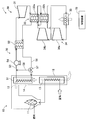
- FIG. 1 is a schematic configuration diagram of a supercritical fluid power generation system according to an embodiment.
- the supercritical fluid power generation system 1 includes a boiler facility 10 having a heat source 11, a supercritical fluid power generation unit 30, an intermediate heat medium circulation unit 50, and a control device 70.
- the supercritical fluid power generation system 1 uses a closed cycle in which the working fluid is a supercritical fluid, specifically, supercritical carbon dioxide (CO 2).
- CO 2 supercritical carbon dioxide
- the boiler equipment 10 burns fuel such as biomass or fossil fuel to serve as a heat source 11, and air is supplied to the heat source 11 via an air heater 12.
- the boiler equipment 10 generates a high-temperature gas (combustion gas) 13 whose temperature has been raised by the heat source 11, and the high-temperature gas 13 is discharged to the outside of the system 1 via the flow path 14.
- the flow path 14 is provided with an air heater 12 and a heat recovery heat exchanger 51, which will be described later, of an intermediate heat medium circulation unit 50 on the upstream side of the air heater 12.
- the air heater 12 is configured as a regenerative heat exchanger that exchanges heat between the high temperature gas 13 heated by the heat source 11 and the air supplied to the heat source 11.
- the heat source 11 is not particularly limited, and various well-known heat sources such as geothermal heat, solar heat, and biomass can be used in addition to thermal power and nuclear power.
- the supercritical fluid power generation unit 30 uses a closed cycle in which the working fluid is a supercritical fluid, specifically, supercritical carbon dioxide (CO 2).
- the supercritical fluid power generation unit 30 includes a turbine 31, a regenerative heat exchanger 32, a cooler 33, and a compression device 34.
- supercritical carbon dioxide heated by the intermediate heat exchanger 52 described later in the intermediate heat medium circulation unit 50 flows in, and while passing through, the supercritical carbon dioxide is expanded to generate mechanical power.
- the turbine 31 can, for example, rotate a drive shaft to drive a generator (none of which is shown), and the generator can generate electricity.
- the supercritical carbon dioxide that has been expanded and worked in the turbine 31 flows out to the regenerated heat exchanger 32.
- the regenerated heat exchanger 32 exchanges heat between the high-temperature supercritical carbon dioxide that flows out to the cooler 33 side via the turbine 31 and the low-temperature supercritical carbon dioxide that has passed through the cooler 33 and the compressor 34. By such heat exchange, the regenerative heat exchanger 32 cools the supercritical carbon dioxide flowing from the turbine 31 to the cooler 33, and heats the supercritical carbon dioxide after passing through the compression device 34.
- the regenerative heat exchanger 32 includes a high-temperature regenerative heat exchanger 32a and a low-temperature regenerative heat exchanger 32b, and performs heat exchange in two stages. The supercritical carbon dioxide heat exchanged by the regenerative heat exchanger 32 flows out to the cooler 33.
- the cooler 33 cools the supercritical carbon dioxide flowing in through the regenerated heat exchanger 32 by the outside air.
- the supercritical carbon dioxide cooled by the cooler 33 flows out to the compression device 34.
- the compression device 34 compresses the supercritical carbon dioxide expanded by the turbine 31 via a predetermined driving force while the supercritical carbon dioxide flows in and passes therethrough.
- the compressor 34 includes a main compressor 34a and a bypass compressor 34b.
- the main compressor 34a compresses supercritical carbon dioxide that has been expanded by the turbine 31 and then cooled through the regenerative heat exchanger 32 and the cooler 33.
- the supercritical carbon dioxide compressed by the main compressor 34a flows out to the high temperature regenerative heat exchanger 32a of the regenerated heat exchanger 32.
- the bypass compressor 34b extracts and compresses supercritical carbon dioxide flowing from the low temperature regenerative heat exchanger 32b to the cooler 33.
- the supercritical carbon dioxide compressed by the bypass compressor 34b flows out to the high temperature regenerative heat exchanger 32a of the regenerative heat exchanger 32.
- the supercritical carbon dioxide that has passed through the high-temperature regenerative heat exchanger 32a flows into the intermediate heat exchanger 52 described later in the intermediate heat medium circulation unit 50 and flows into the turbine 31 again. In this way, supercritical carbon dioxide is circulated in the supercritical fluid power generation unit 30.
- the intermediate heat medium circulation unit 50 includes a heat recovery heat exchanger 51 and an intermediate heat exchanger 52 that circulate a liquid heat medium and transfer the heat of the boiler equipment 10 to the supercritical fluid power generation unit 30.
- a chemically inert molten salt hereinafter, simply referred to as “molten salt”
- thermal oil is used in addition to the molten salt.
- the heat recovery heat exchanger 51 exchanges heat between the molten salt passing through the inside and the high temperature gas 13 heated by the heat source 11. Therefore, the molten salt circulated in the intermediate heat medium circulation unit 50 is heated by the high temperature gas 13.
- the intermediate heat exchanger 52 exchanges heat between the molten salt passing through the inside and the supercritical carbon dioxide heated by the regenerated heat exchanger 32. Therefore, the intermediate heat medium circulation unit 50 can recover the heat of the heat source 11 by the heat recovery heat exchanger 51, and transfer the recovered heat to the supercritical fluid power generation unit 30 by the intermediate heat exchanger 52.
- the outlet of the heat recovery heat exchanger 51 and the inlet of the intermediate heat exchanger 52 are connected by a high temperature side flow path 53, and a pump 54 for pumping molten salt is provided in the middle of the high temperature side flow path 53.
- the outlet of the intermediate heat exchanger 52 and the inlet of the heat recovery heat exchanger 51 are connected by a low temperature side flow path 56.
- a three-way valve (adjustment valve) 57 is provided in the middle of the low temperature side flow path 56.
- the three-way valve 57 and the downstream side of the pump 54 in the high temperature side flow path 53 are connected by a bypass flow path 58.
- the bypass flow path 58 connects the upstream side and the downstream side of the intermediate heat exchanger 52, and connects the upstream side and the downstream side of the heat recovery heat exchanger 51.
- the three-way valve 57 switches between the presence / absence of circulation of molten salt in the bypass flow path 58 and the presence / absence of circulation of molten salt in the intermediate heat exchanger 52, and the molten salt passing through the intermediate heat exchanger 52 is the heat recovery heat exchanger 51. It is possible to switch which of the bypass flow path 58 and the bypass flow path 58.
- the molten salt in the three-way valve 57 when the outflow destination of the molten salt in the three-way valve 57 is switched to the heat recovery heat exchanger 51 to drive the pump 54, the molten salt is circulated in the heat recovery heat exchanger 51 and the intermediate heat exchanger 52.
- the molten salt flows through the heat recovery heat exchanger 51 and is heated by the high temperature gas 13 generated in the boiler equipment 10.
- the heated molten salt flows into the intermediate heat exchanger 52 via the high temperature side flow path 53, and transfers heat to the supercritical carbon dioxide circulating in the supercritical fluid power generation unit 30.
- the molten salt that has transferred heat through the intermediate heat exchanger 52 returns to the heat recovery heat exchanger 51 through the low temperature side flow path 56.
- the intermediate heat medium circulation unit 50 since the heat medium is a molten salt, high corrosion resistance in piping or the like is not required. Therefore, an inexpensive carbon steel pipe used in a conventional steam power generation system can be used for each part of the intermediate heat medium circulation part 50 to suppress an increase in equipment cost.
- the heat recovery heat exchanger 51 since heat is exchanged between the high temperature gas that becomes a gas and the molten salt that becomes a liquid, it is necessary to increase the heat transfer area in order to improve the heat recovery efficiency. By using it, it is possible to suppress an increase in cost. In other words, heat recovery can be made highly efficient, and an increase in equipment cost can be suppressed.
- the intermediate heat exchanger 52 heat exchange occurs between the molten salt that becomes a liquid and supercritical carbon dioxide, and since both of them have a high density, the heat recovery efficiency should be maintained well even if the heat transfer area is small. Can be done. Specifically, the heat transfer from the molten salt to the supercritical carbon dioxide is about 10 times higher than that from the case where the heat is transferred from the high temperature gas to the supercritical carbon dioxide.
- the heat transfer part such as the pipe through which supercritical carbon dioxide flows can be made small and compact. Since high-temperature supercritical carbon dioxide flows in such a heat transfer section, it is necessary to use an expensive material having high corrosion resistance. The amount used can be significantly reduced. As a result, the supercritical fluid power generation unit 30 using high-temperature supercritical carbon dioxide can improve the efficiency of power generation and suppress the cost increase for corrosion countermeasures.
- the circulation of the molten salt to the heat recovery heat exchanger 51 can be stopped.
- the molten salt delivered to the intermediate heat exchanger 52 is not heated, and the temperature of the molten salt is lowered, so that the output of the supercritical fluid power generation unit 30 can be lowered.
- the temperature of the molten salt rises and the output of the supercritical fluid power generation unit 30 can be increased.
- the embodiment of the present invention is not limited to the above embodiment, and may be variously modified, replaced, or modified without departing from the spirit of the technical idea of the present invention. Furthermore, if the technical idea of the present invention can be realized in another way by the advancement of technology or another technology derived from it, it may be carried out by using that method. Therefore, the scope of claims covers all embodiments that may be included within the scope of the technical idea of the present invention.
- the regenerative heat exchanger 32 is provided with the two-stage regenerated heat exchangers 32a and 32b, but the present invention is not limited to this, and one of them may be omitted, or the regenerated heat exchanger 32 may be further regenerated. A heat exchanger may be added. Further, the supercritical fluid power generation system 1 may be configured without the regenerated heat exchanger 32 itself. However, since the supercritical fluid power generation system 1 has the regenerated heat exchanger 32, it is advantageous in that the supercritical carbon dioxide introduced into the intermediate heat exchanger 52 can be efficiently heated.
- bypass compressor 34b in the compression device 34 may be omitted.
- the adjusting valve in the intermediate heat medium circulation unit 50 is not limited to the above-mentioned three-way valve 57, and other ones capable of simultaneously adjusting the flow rate of the molten salt to the bypass flow path 58 and the flow rate of the molten salt to the intermediate heat exchanger 52. It may be a configuration or the like.
- the supercritical fluid is not limited to supercritical carbon dioxide as long as the supercritical fluid power generation system 1 can be operated as in each of the above embodiments.
Landscapes
- Engineering & Computer Science (AREA)
- Chemical & Material Sciences (AREA)
- Combustion & Propulsion (AREA)
- Mechanical Engineering (AREA)
- General Engineering & Computer Science (AREA)
- Engine Equipment That Uses Special Cycles (AREA)
Priority Applications (1)
| Application Number | Priority Date | Filing Date | Title |
|---|---|---|---|
| PCT/JP2020/011142 WO2021181663A1 (fr) | 2020-03-13 | 2020-03-13 | Système de production d'énergie à fluide supercritique |
Applications Claiming Priority (1)
| Application Number | Priority Date | Filing Date | Title |
|---|---|---|---|
| PCT/JP2020/011142 WO2021181663A1 (fr) | 2020-03-13 | 2020-03-13 | Système de production d'énergie à fluide supercritique |
Publications (1)
| Publication Number | Publication Date |
|---|---|
| WO2021181663A1 true WO2021181663A1 (fr) | 2021-09-16 |
Family
ID=77672159
Family Applications (1)
| Application Number | Title | Priority Date | Filing Date |
|---|---|---|---|
| PCT/JP2020/011142 Ceased WO2021181663A1 (fr) | 2020-03-13 | 2020-03-13 | Système de production d'énergie à fluide supercritique |
Country Status (1)
| Country | Link |
|---|---|
| WO (1) | WO2021181663A1 (fr) |
Cited By (2)
| Publication number | Priority date | Publication date | Assignee | Title |
|---|---|---|---|---|
| CN108487951A (zh) * | 2018-04-19 | 2018-09-04 | 安徽工业大学 | 一种利用钢渣热能、燃气-超临界二氧化碳联合发电方法 |
| CN119467082A (zh) * | 2024-11-20 | 2025-02-18 | 上海电气集团股份有限公司 | 一种基于绿碳循环的能源系统及其运行方法和控制方法 |
Citations (4)
| Publication number | Priority date | Publication date | Assignee | Title |
|---|---|---|---|---|
| JP2017504744A (ja) * | 2013-11-22 | 2017-02-09 | ザ ケマーズ カンパニー エフシー リミテッド ライアビリティ カンパニー | テトラフルオロプロペン及びテトラフルオロエタンを含む組成物、動力サイクルにおけるその使用、並びに動力サイクル装置 |
| JP2018519454A (ja) * | 2015-05-04 | 2018-07-19 | ドゥサン ヘヴィー インダストリーズ アンド コンストラクション カンパニー リミテッド | 超臨界二酸化炭素発電システム |
| JP2019124188A (ja) * | 2018-01-18 | 2019-07-25 | 株式会社神戸製鋼所 | 熱エネルギー回収装置 |
| JP3223710U (ja) * | 2019-08-16 | 2019-10-24 | 四季洋圃生物機電股▲ふん▼有限公司 | 超臨界発電構造 |
-
2020
- 2020-03-13 WO PCT/JP2020/011142 patent/WO2021181663A1/fr not_active Ceased
Patent Citations (4)
| Publication number | Priority date | Publication date | Assignee | Title |
|---|---|---|---|---|
| JP2017504744A (ja) * | 2013-11-22 | 2017-02-09 | ザ ケマーズ カンパニー エフシー リミテッド ライアビリティ カンパニー | テトラフルオロプロペン及びテトラフルオロエタンを含む組成物、動力サイクルにおけるその使用、並びに動力サイクル装置 |
| JP2018519454A (ja) * | 2015-05-04 | 2018-07-19 | ドゥサン ヘヴィー インダストリーズ アンド コンストラクション カンパニー リミテッド | 超臨界二酸化炭素発電システム |
| JP2019124188A (ja) * | 2018-01-18 | 2019-07-25 | 株式会社神戸製鋼所 | 熱エネルギー回収装置 |
| JP3223710U (ja) * | 2019-08-16 | 2019-10-24 | 四季洋圃生物機電股▲ふん▼有限公司 | 超臨界発電構造 |
Cited By (3)
| Publication number | Priority date | Publication date | Assignee | Title |
|---|---|---|---|---|
| CN108487951A (zh) * | 2018-04-19 | 2018-09-04 | 安徽工业大学 | 一种利用钢渣热能、燃气-超临界二氧化碳联合发电方法 |
| CN108487951B (zh) * | 2018-04-19 | 2023-09-15 | 安徽工业大学 | 一种利用钢渣热能、燃气-超临界二氧化碳联合发电方法 |
| CN119467082A (zh) * | 2024-11-20 | 2025-02-18 | 上海电气集团股份有限公司 | 一种基于绿碳循环的能源系统及其运行方法和控制方法 |
Similar Documents
| Publication | Publication Date | Title |
|---|---|---|
| RU2673959C2 (ru) | Система и способ регенерации энергии отходящего тепла | |
| US10400636B2 (en) | Supercritical CO2 generation system applying plural heat sources | |
| US10344626B2 (en) | Hybrid power generation system | |
| CN112343680A (zh) | 超临界二氧化碳发电系统及其运行控制方法 | |
| US10287926B2 (en) | Supercritical CO2 generation system applying recuperator per each heat source | |
| EP3008297B1 (fr) | Agencement et procédé d'utilisation de chaleur perdue | |
| WO2021181663A1 (fr) | Système de production d'énergie à fluide supercritique | |
| US10731515B2 (en) | Hybrid type power generation system | |
| KR101812919B1 (ko) | 복합 초임계 이산화탄소 발전 시스템 | |
| US9982571B2 (en) | Arrangement and method for the utilization of waste heat | |
| RU106307U1 (ru) | Станция регулирования давления системы распределения природного газа (варианты) | |
| US10273832B2 (en) | Supercritical carbon dioxide power generation system utilizing plural heat sources | |
| KR101864983B1 (ko) | 초임계 이산화탄소 발전 시스템 | |
| JP6858821B2 (ja) | ガスタービンの吸気温調システムおよび発電プラント | |
| JP5511429B2 (ja) | 熱利用システム | |
| WO2021181483A1 (fr) | Système de génération d'énergie à fluide supercritique | |
| US10202873B2 (en) | Supercritical CO2 generation system applying plural heat sources | |
| JP2019007379A (ja) | 熱エネルギー回収システム及びそれを搭載する船舶 | |
| KR20160017283A (ko) | 초임계 이산화탄소 발전시스템 | |
| KR102021901B1 (ko) | 병렬 히터를 적용한 초임계 이산화탄소 발전 시스템 | |
| KR20160066539A (ko) | 초임계 이산화탄소 발전시스템 | |
| JP4936966B2 (ja) | 復水熱交換システムおよび復水熱交換器の制御方法 | |
| CN116282375B (zh) | 一种基于超临界二氧化碳布雷顿循环的余热回收系统 | |
| KR101939029B1 (ko) | 복수의 열원을 활용한 초임계 이산화탄소 발전 시스템 | |
| JP7449712B2 (ja) | ランキンサイクル装置およびその運転方法 |
Legal Events
| Date | Code | Title | Description |
|---|---|---|---|
| 121 | Ep: the epo has been informed by wipo that ep was designated in this application |
Ref document number: 20924254 Country of ref document: EP Kind code of ref document: A1 |
|
| NENP | Non-entry into the national phase |
Ref country code: DE |
|
| 122 | Ep: pct application non-entry in european phase |
Ref document number: 20924254 Country of ref document: EP Kind code of ref document: A1 |
|
| NENP | Non-entry into the national phase |
Ref country code: JP |