WO2021181452A1 - 商品検出装置、商品検出方法、及びプログラム - Google Patents
商品検出装置、商品検出方法、及びプログラム Download PDFInfo
- Publication number
- WO2021181452A1 WO2021181452A1 PCT/JP2020/009985 JP2020009985W WO2021181452A1 WO 2021181452 A1 WO2021181452 A1 WO 2021181452A1 JP 2020009985 W JP2020009985 W JP 2020009985W WO 2021181452 A1 WO2021181452 A1 WO 2021181452A1
- Authority
- WO
- WIPO (PCT)
- Prior art keywords
- product
- output
- state
- images
- detection device
- Prior art date
Links
Images


Classifications
-
- G—PHYSICS
- G06—COMPUTING; CALCULATING OR COUNTING
- G06Q—INFORMATION AND COMMUNICATION TECHNOLOGY [ICT] SPECIALLY ADAPTED FOR ADMINISTRATIVE, COMMERCIAL, FINANCIAL, MANAGERIAL OR SUPERVISORY PURPOSES; SYSTEMS OR METHODS SPECIALLY ADAPTED FOR ADMINISTRATIVE, COMMERCIAL, FINANCIAL, MANAGERIAL OR SUPERVISORY PURPOSES, NOT OTHERWISE PROVIDED FOR
- G06Q30/00—Commerce
- G06Q30/02—Marketing; Price estimation or determination; Fundraising
- G06Q30/0281—Customer communication at a business location, e.g. providing product or service information, consulting
-
- G—PHYSICS
- G06—COMPUTING; CALCULATING OR COUNTING
- G06Q—INFORMATION AND COMMUNICATION TECHNOLOGY [ICT] SPECIALLY ADAPTED FOR ADMINISTRATIVE, COMMERCIAL, FINANCIAL, MANAGERIAL OR SUPERVISORY PURPOSES; SYSTEMS OR METHODS SPECIALLY ADAPTED FOR ADMINISTRATIVE, COMMERCIAL, FINANCIAL, MANAGERIAL OR SUPERVISORY PURPOSES, NOT OTHERWISE PROVIDED FOR
- G06Q30/00—Commerce
- G06Q30/02—Marketing; Price estimation or determination; Fundraising
-
- G—PHYSICS
- G06—COMPUTING; CALCULATING OR COUNTING
- G06T—IMAGE DATA PROCESSING OR GENERATION, IN GENERAL
- G06T7/00—Image analysis
- G06T7/0002—Inspection of images, e.g. flaw detection
- G06T7/0004—Industrial image inspection
-
- G—PHYSICS
- G06—COMPUTING; CALCULATING OR COUNTING
- G06V—IMAGE OR VIDEO RECOGNITION OR UNDERSTANDING
- G06V20/00—Scenes; Scene-specific elements
- G06V20/50—Context or environment of the image
- G06V20/52—Surveillance or monitoring of activities, e.g. for recognising suspicious objects
Definitions
- the present invention relates to a product detection device, a product detection method, and a program.
- Documents aimed at detecting this behavior include, for example, Patent Documents 1 and 2.
- Patent Document 1 describes that the position of a customer's hand and the position of a product are specified by processing an image, and the number of times the customer reaches out is totaled for each product using these positions. There is. Patent Document 1 also describes that the time from when a customer picks up a product to when the product is returned is displayed on a display unit.
- Patent Document 2 describes that by processing an image, the attitude of the customer is estimated and the display state of the product is analyzed, thereby determining that the product has been returned to the display location.
- One of an object of the present invention is to enable it to detect that a customer has returned a product to the product placement area without detecting the customer.
- the acquisition means for acquiring a plurality of first images generated by the first imaging means for photographing the product mounting area at different timings, and An image processing means for detecting a first state in which a new product is continuously present in the product placement area for a reference time or longer by processing the plurality of first images.
- An output means that outputs the first output when the first state is detected, and A product detection device comprising the above is provided.
- the computer The first imaging means for photographing the product mounting area acquires a plurality of first images generated at different timings, and obtains a plurality of first images.
- a first state in which a new product is continuously present in the product placement area for a reference time or longer is detected.
- a product detection method for performing a first output when the first state is detected is provided.
- the present invention it is possible to detect that a customer has returned a product to the product placement area without detecting the customer.
- FIG. 1 is a diagram for explaining a usage environment of the product detection device 10 according to the present embodiment.
- the product detection device 10 is used together with the image pickup unit 20 (an example of the first image pickup unit).
- the image pickup unit 20 repeatedly takes an image of the product placement area, for example, the product shelf 40.
- the frame rate of the imaging unit 20 is arbitrary, but is, for example, 10 frames / sec or more.
- the product 50 is placed on the product shelf 40.
- the product detection device 10 detects that the product 50 has been returned to the product shelf 40 after the product 50 has been taken out from the product shelf 40 by the customer by processing the image generated by the imaging unit 20.
- the store in which the image pickup unit 20 and the product shelf 40 are arranged may be a general store such as a convenience store or a supermarket, or a corner of a place other than the general store such as an office (for example, a so-called micro store). It may be.
- a plurality of imaging units 20 may be provided for one product shelf 40. In this case, each of the plurality of imaging units 20 may image different regions of the product shelf 40. Further, a plurality of imaging units 20 may be provided for one product mounting area. In any case, the image pickup unit 20 transmits the image generated by the image pickup unit 20 to the product detection device 10 in association with the image pickup unit identification information assigned to the image pickup unit 20 and the generation date and time of the image. ..
- the detection result by the product detection device 10 is output to the information processing device 30.
- the user of the information processing device 30 can determine the products to be arranged on the product shelf 40 by statistically processing the detection result by the product detection device 10 using the information processing device 30, and determine the products 50 and / or the products 50. Determine the package of.
- FIG. 2 is a diagram showing an example of the functional configuration of the product detection device 10.
- the product detection device 10 includes an acquisition unit 110, an image processing unit 120, and an output unit 130.
- the acquisition unit 110 acquires a plurality of images (an example of the first image) generated by the imaging unit 20 in association with the generation date and time of the image. As described above, these plurality of images are generated at different timings from each other.
- the image processing unit 120 By processing a plurality of images, the image processing unit 120 detects that a new product has been continuously present on the product shelf 40 for a reference time or longer (hereinafter referred to as the first state). ..
- the reference time used here is preferably, for example, 0.5 seconds or more.
- the reference time may be counted by the number of frames.
- the output unit 130 outputs the first output when the first state is detected.
- the first output indicates that the product 50 was returned to the product shelf 40 after the product 50 was taken out from the product shelf 40 by the customer.
- the output unit 130 performs the first output when the first state is detected at the timing when the store clerk does not replenish the product shelf 40 with the product.
- the image processing unit 120 may store the date and time when the store clerk replenishes the product, and may use the image taken at a timing other than this time. Further, the image processing unit 120 determines that when a plurality of products 50 (for example, two or more or three or more) are continuously placed on the product shelf 40, the clerk replenishes the product shelf 40 with the product 50. , May be excluded from the subject of the first state. At this time, the image processing unit 120 may set a condition for excluding the products 50 that are continuously placed on the product shelves 40 from each other with the same product name from the target of the first state.
- the image processing unit 120 specifies the product name of the product 50 returned to the product shelf 40 by processing the image generated by the imaging unit 20. This identification is performed, for example, by feature matching.
- the image processing result of the image processing unit 120 is stored in the detection result storage unit 122.
- An example of the information stored in the detection result storage unit 122 will be described later with reference to FIG.
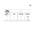
- FIG. 3 shows an example of the information stored in the detection result storage unit 122.
- the detection result storage unit 122 stores information indicating the product name of the product (for example, product code: hereinafter referred to as the product name), the arrangement position of the product on the product shelf 40, and the product for each product. It stores the number of detections and information indicating whether or not the product has already been installed (described as "installed” in FIG. 3).
- installed becomes "true”
- installed becomes "false”.
- the detection result storage unit 122 stores the above-mentioned information for each of the plurality of imaging units 20 in association with the imaging unit identification information of the imaging unit 20. doing.
- FIG. 4 is a diagram showing a hardware configuration example of the product detection device 10.
- the product detection device 10 includes a bus 1010, a processor 1020, a memory 1030, a storage device 1040, an input / output interface 1050, and a network interface 1060.
- the bus 1010 is a data transmission path for the processor 1020, the memory 1030, the storage device 1040, the input / output interface 1050, and the network interface 1060 to transmit and receive data to and from each other.
- the method of connecting the processors 1020 and the like to each other is not limited to the bus connection.
- the processor 1020 is a processor realized by a CPU (Central Processing Unit), a GPU (Graphics Processing Unit), or the like.
- the memory 1030 is a main storage device realized by a RAM (Random Access Memory) or the like.
- the storage device 1040 is an auxiliary storage device realized by an HDD (Hard Disk Drive), an SSD (Solid State Drive), a memory card, a ROM (Read Only Memory), or the like.
- the storage device 1040 stores a program module that realizes each function of the product detection device 10 (for example, an acquisition unit 110, an image processing unit 120, and an output unit 130).
- the processor 1020 reads each of these program modules into the memory 1030 and executes them, each function corresponding to the program module is realized.
- the storage device 1040 also functions as a detection result storage unit 122.
- the input / output interface 1050 is an interface for connecting the product detection device 10 and various input / output devices.
- the network interface 1060 is an interface for connecting the product detection device 10 to the network.
- This network is, for example, LAN (Local Area Network) or WAN (Wide Area Network).
- the method of connecting the network interface 1060 to the network may be a wireless connection or a wired connection.
- the product detection device 10 communicates with the image pickup unit 20 and the information processing device 30 via, for example, the network interface 1060.
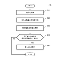
- FIG. 5 is a diagram showing a first example of processing performed by the product detection device 10.
- the product detection device 10 performs the processing shown in this figure for each of a plurality of images generated by the imaging unit 20. It should be noted that this process may be performed every time the acquisition unit 110 acquires an image, or may be performed in a batch system.
- the image processing unit 120 of the product detection device 10 processes the image to be processed, and for each product 50 placed on the product shelf 40, the product name (an example of product identification information) of the product and the product thereof. Recognize the position (step S10). Then, the image processing unit 120 determines whether or not the new product 50 is placed on the product shelf 40 by using the processing result of step S10 and the information stored in the detection result storage unit 122 (step S20). ).
- the image processing unit 120 when the image processing unit 120 has a combination of product names and positions of the product 50 generated in step S10 that is not stored in the detection result storage unit 122, the image processing unit 120 selects the product 50 corresponding to the combination. , It is determined that the product is newly placed on the product shelf 40. Then, the image processing unit 120 stores the combination in the detection result storage unit 122 (step S30). At this time, in the combination, the number of product detections is "1", and "installed” is "false” (step S30).
- the image processing unit 120 when the image processing unit 120 stores the combination of the product name and the position of the product 50 generated in step S10 in the detection result storage unit 122, the image processing unit 120 receives the detection result storage unit 122. Of these, increase the number of detections of the product by one. Here, the image processing unit 120 does not have to increase the number of detections for products whose "installed” is “true”. Then, the image processing unit 120 determines that the product 50 whose number of detections after the change is equal to or greater than the standard has been placed on the product shelf 40 before that, and "installs” the product in the detection result storage unit 122. Change “completed” from “false” to "true” (step S30).
- the area corresponding to the product in the image is specified by a rectangle. Then, "whether or not they are at the same position" is determined by the overlap rate of this rectangle. For example, when the duplication rate is equal to or higher than the reference value, it is determined that the positions are the same.
- the image processing unit 120 means that the product 50 is continuously detected for the reference time (step). S40: Yes). Then, the product 50 is returned to the product shelf 40 by the first state described above, that is, the customer. Therefore, the output unit 130 outputs the first output to the information processing device 30 (step S50).
- the output unit 130 includes information for identifying the product 50 whose elapsed time is equal to or longer than the reference time, for example, information indicating the product name of the product 50 in the first output.
- the image processing unit 120 among the information about the product 50 stored in the detection result storage unit 122, the product 50 whose "installed” is “true”, the newly registered product 50, and the number of detections are Information other than the product 50, which has been increased by one, may be deleted. In this way, information that becomes noise is erased from the detection result storage unit 122.
- the product detection device 10 captures the process shown in FIG. This is done for each section 20, that is, for each product placement area.
- the output unit 130 includes information for specifying the product placement area in which the first state is detected in the first output.
- FIG. 6 is a diagram showing a second example of processing performed by the product detection device 10.
- two imaging units 20 are installed for one product mounting area. Both of these two imaging units 20 repeatedly image the product mounting area. Further, also in the example shown in this figure, the product detection device 10 performs the processing shown in this figure for each product placement area. It should be noted that this process may be performed every time the acquisition unit 110 acquires an image, or may be performed in a batch system.
- the acquisition unit 110 acquires an image generated by one imaging unit 20 (hereinafter referred to as a first image) and an image generated by the other imaging unit 20 (hereinafter referred to as a second image), and first.
- the processing shown in steps S10 to S40 of FIG. 5 is performed using the image, and the processing shown in steps S10 to S40 of FIG. 5 is performed using the second image (step S110).
- the generation timing of the first image is the same as the generation timing of the second image.
- the image processing unit 120 uses the first image to determine whether or not the above-mentioned first state has been reached, and uses the second image to determine whether or not the above-mentioned first state has been reached. do.
- step S120: Yes when the processing result using the first image and the processing result using the second image match (step S120: Yes), the output unit 130 outputs the first output in the same manner as in step S50 of FIG. (Step S130).
- step S120: No if the processing result using the first image and the processing result using the second image do not match (step S120: No), the output unit 130 has a high possibility that some abnormality has occurred.
- An output different from the first output (hereinafter referred to as the second output) is performed (step S140).
- the processing result using the first image shows the first state
- the processing result using the second image does not show the first state.
- the product name of the product 50 recognized using the first image is different from the product name of the product 50 recognized using the second image.
- the second output contains information indicating that, for example, some abnormality has occurred.
- the second output may include the first image and the second image. In this way, the user of the information processing apparatus 30 can determine the content of the abnormality by visually recognizing the first image and the second image.
- step S170 the image processing unit 120 updates the detection result storage unit 122 (step S170).
- the details of the processing performed here are the same as in step S50 of FIG.
- the present embodiment it is determined whether or not the product 50 has been returned to the product shelf 40 by the customer by using the elapsed time since the product 50 was placed on the product shelf 40. Therefore, it is possible to detect that the customer has returned the product to the product placement area without detecting the customer.
- FIG. 7 is a diagram showing an imaging unit 20 according to the second embodiment.
- FIG. 8 is a diagram showing how to use the imaging unit 20.
- the image pickup unit 20 used together with the product detection device 10 is a part of the image pickup device 200.
- the imaging device 200 has two imaging units 210.
- Each of the two imaging units 210 has an illumination unit 220 and an imaging unit 20.
- the light emitting surface of the lighting unit 220 extends in one direction, and has a light emitting unit and a cover that covers the light emitting unit.
- the illumination unit 220 mainly emits light in a direction orthogonal to the extending direction of the light emitting surface.
- the light emitting unit has a light emitting element such as an LED, and emits light in a direction not covered by the cover.
- the light emitting element is an LED, a plurality of LEDs are arranged in a direction in which the illumination unit 220 extends (vertical direction in the drawing).
- the image pickup unit 20 is provided on one end side of the illumination unit 220, and the imaging range is the direction in which the light of the illumination unit 220 is radiated.
- the imaging range is the direction in which the light of the illumination unit 220 is radiated.
- the image pickup unit 20 has an image pickup range of downward and diagonally lower right.
- the image pickup unit 20 has an image pickup range above and diagonally above the left.
- the two imaging units 210 are attached to the front frame (or the front of the side walls on both sides) 42 of the product shelf 40.
- the first imaging unit 210 is attached to one front frame 42 in a direction in which the imaging unit 20 is located downward, and the second imaging unit 210 is on the opposite side of the first imaging unit 210.
- the imaging unit 20 is attached to the front frame 42 so as to be located upward.
- the imaging unit 20 of the first imaging unit 210 images the upper side and the diagonally upper side so as to include the opening of the product shelf 40 in the imaging range.
- the imaging unit 20 of the second imaging unit 210 images downward and diagonally downward so as to include the opening of the product shelf 40 in the imaging range.
- the product detection device 10 generates various information shown in the above embodiment by processing the images captured by the imaging units 20 of the two imaging units 210, that is, the images captured by the two imaging units 20. ..
- An acquisition means for acquiring a plurality of first images generated at different timings by the first imaging means for photographing the product mounting area, and an acquisition means.
- An image processing means for detecting a first state in which a new product is continuously present in the product placement area for a reference time or longer by processing the plurality of first images.
- An output means that outputs the first output when the first state is detected, and Commodity detection device. 2.
- the output means is a product detection device that outputs the first output when the first state is detected at a timing when the store clerk does not replenish the product in the product placement area. 3. 3.
- the first imaging means is provided for each of the plurality of product mounting areas.
- the image processing means detects the first state by processing the plurality of first images generated by the first imaging means corresponding to the product mounting area for each product mounting area.
- the output means is a product detection device that includes information for identifying the product placement area in which the first state is detected in the first output. 4.
- the image processing means generates product identification information that identifies the product name of the new product, and generates product identification information.
- the output means is a product detection device that includes the product identification information in the first output. 5.
- the acquisition means acquires a plurality of second images generated by the second imaging means that captures the same product mounting area as the first imaging means at different timings.
- the image processing means further processes the second image to generate the product identification information of the new product.
- the output means is different from the first output when the product identification information generated by using the first image is different from the product identification information generated by using the second image.
- a product detection device that outputs. 6.
- the acquisition means acquires a plurality of second images generated by the second imaging means that captures the same product mounting area as the first imaging means at different timings.
- the image processing means further detects the first state by processing the plurality of second images, and obtains the first state.
- the output means The first result, which is the processing result of the plurality of first images, indicates the first state, and is generated at the same time as the plurality of first images used when the first state is detected.
- the second result which is the processing result of the plurality of second images
- the first output is performed.
- a product detection device that outputs a second output different from the first output when the first result indicates the first state and the second result does not indicate the first state.
- the computer The first imaging means for photographing the product mounting area acquires a plurality of first images generated at different timings, and obtains a plurality of first images. By processing the plurality of first images, a first state in which a new product is continuously present in the product placement area for a reference time or longer is detected.
- a product detection method that outputs a first output when the first state is detected.
- the computer is a product detection method that outputs the first output when the first state is detected at a timing when the store clerk does not replenish the product in the product placement area.
- the first imaging means is provided for each of the plurality of product mounting areas.
- the computer The first state is detected by processing the plurality of first images generated by the first imaging means corresponding to the product mounting area for each product mounting area.
- a product detection method in which the first output includes information for identifying the product placement area in which the first state is detected. 10.
- the computer Generate product identification information that identifies the product name of the new product, A product detection method that includes the product identification information in the first output. 11.
- the computer A plurality of second images generated by the second imaging means for photographing the same product mounting area as the first imaging means at different timings are acquired. Further, by processing the second image, the product identification information of the new product is generated, and the product identification information is generated. Product detection that performs a second output different from the first output when the product identification information generated using the first image is different from the product identification information generated using the second image. Method. 12.
- the computer A plurality of second images generated by the second imaging means for photographing the same product mounting area as the first imaging means at different timings are acquired. Further, the first state is detected by processing the plurality of second images, and the first state is detected.
- the first result which is the processing result of the plurality of first images, indicates the first state, and is generated at the same time as the plurality of first images used when the first state is detected.
- the second result which is the processing result of the plurality of second images
- indicates the first state the first output is performed.
- the output function is a program that outputs the first output when the first state is detected at a timing when the store clerk does not replenish the product in the product placement area. 15.
- the first imaging means is provided for each of the plurality of product mounting areas.
- the image processing function detects the first state by processing the plurality of first images generated by the first imaging means corresponding to the product mounting area for each product mounting area.
- the output function is a program that includes information for specifying the product placement area in which the first state is detected in the first output. 16.
- the image processing function generates product identification information that identifies the product name of the new product, and generates product identification information.
- the output function is a program that includes the product identification information in the first output. 17.
- the acquisition function acquires a plurality of second images generated by the second imaging means for photographing the same product mounting area as the first imaging means at different timings.
- the image processing function further processes the second image to generate the product identification information of the new product.
- the output function is different from the first output when the product identification information generated by using the first image is different from the product identification information generated by using the second image.
- the acquisition function acquires a plurality of second images generated by the second imaging means for photographing the same product mounting area as the first imaging means at different timings.
- the image processing function detects the first state by further processing the plurality of second images.
- the output function is The first result, which is the processing result of the plurality of first images, indicates the first state, and is generated at the same time as the plurality of first images used when the first state is detected.
- the second result which is the processing result of the plurality of second images, indicates the first state
- the first output is performed.
- a program that outputs a second output different from the first output when the first result indicates the first state and the second result does not indicate the first state.
Landscapes
- Engineering & Computer Science (AREA)
- Business, Economics & Management (AREA)
- Accounting & Taxation (AREA)
- Development Economics (AREA)
- Finance (AREA)
- Strategic Management (AREA)
- Physics & Mathematics (AREA)
- Theoretical Computer Science (AREA)
- General Physics & Mathematics (AREA)
- Entrepreneurship & Innovation (AREA)
- Marketing (AREA)
- General Business, Economics & Management (AREA)
- Economics (AREA)
- Game Theory and Decision Science (AREA)
- Quality & Reliability (AREA)
- Computer Vision & Pattern Recognition (AREA)
- Multimedia (AREA)
- Management, Administration, Business Operations System, And Electronic Commerce (AREA)
Abstract
商品検出装置(10)は、取得部(110)、画像処理部(120)、及び出力部(130)を備えている。取得部(110)は、撮像部(20)が生成した複数の画像(第1画像の一例)を、当該画像の生成日時に対応付けて取得する。これら複数の画像は、互いに異なるタイミングで生成されている。画像処理部(120)は、複数の画像を処理することにより、新たな商品が基準時間以上連続して商品棚(40)に存在している状態(以下、第1状態と記載)になったことを検知する。出力部(130)は、第1状態が検知された場合に第1出力を行う。第1出力は、顧客によって商品棚(40)から商品(50)が取り出された後に、その商品(50)が商品棚(40)に戻されたことを示している。
Description
本発明は、商品検出装置、商品検出方法、及びプログラムに関する。
店舗における顧客の行動の一つに、手に取った商品を商品棚に戻すことがある。この行動を検出することを目的とした文献として、例えば特許文献1及び2がある。
特許文献1には、画像を処理することにより顧客の手の位置及び商品の位置を特定し、これらの位置を用いて、顧客が手を伸ばした回数を商品ごとに集計することが記載されている。特許文献1では、顧客が商品を手に取ってから当該商品を戻すまでの時間を表示部に表示することも記載されている。
特許文献2には、画像を処理することにより、顧客の姿勢を推定するとともに商品の陳列状態を解析し、これにより、商品を陳列場所に戻す行動があったと判定することが記載されている。
上記した2つの特許文献では、顧客が商品を商品載置領域に戻したことを検知するためには、画像処理により顧客を検出する必要がある。本発明の目的の一つは、顧客を検出しなくても、顧客が商品を商品載置領域に戻したことを検知できるようにすることにある。
本発明によれば、商品載置領域を撮影する第1撮像手段が互いに異なるタイミングで生成した複数の第1画像を取得する取得手段と、
前記複数の第1画像を処理することにより、新たな商品が基準時間以上連続して前記商品載置領域に存在している状態である第1状態を検知する画像処理手段と、
前記第1状態が検知された場合に第1出力を行う出力手段と、
を備える商品検出装置が提供される。
前記複数の第1画像を処理することにより、新たな商品が基準時間以上連続して前記商品載置領域に存在している状態である第1状態を検知する画像処理手段と、
前記第1状態が検知された場合に第1出力を行う出力手段と、
を備える商品検出装置が提供される。
本発明によれば、コンピュータが、
商品載置領域を撮影する第1撮像手段が互いに異なるタイミングで生成した複数の第1画像を取得し、
前記複数の第1画像を処理することにより、新たな商品が基準時間以上連続して前記商品載置領域に存在している状態である第1状態を検知し、
前記第1状態が検知された場合に第1出力を行う商品検出方法が提供される。
商品載置領域を撮影する第1撮像手段が互いに異なるタイミングで生成した複数の第1画像を取得し、
前記複数の第1画像を処理することにより、新たな商品が基準時間以上連続して前記商品載置領域に存在している状態である第1状態を検知し、
前記第1状態が検知された場合に第1出力を行う商品検出方法が提供される。
本発明によれば、コンピュータに、
商品載置領域を撮影する第1撮像手段が互いに異なるタイミングで生成した複数の第1画像を取得する機能と、
前記複数の第1画像を処理することにより、新たな商品が基準時間以上連続して前記商品載置領域に存在している状態である第1状態を検知する機能と、
前記第1状態が検知された場合に第1出力を行う機能と、
を行わせるプログラムが提供される。
商品載置領域を撮影する第1撮像手段が互いに異なるタイミングで生成した複数の第1画像を取得する機能と、
前記複数の第1画像を処理することにより、新たな商品が基準時間以上連続して前記商品載置領域に存在している状態である第1状態を検知する機能と、
前記第1状態が検知された場合に第1出力を行う機能と、
を行わせるプログラムが提供される。
本発明によれば、顧客を検出しなくても、顧客が商品を商品載置領域に戻したことを検知できるようにすることができる。
上述した目的、およびその他の目的、特徴および利点は、以下に述べる好適な実施の形態、およびそれに付随する以下の図面によってさらに明らかになる。
以下、本発明の実施の形態について、図面を用いて説明する。尚、すべての図面において、同様な構成要素には同様の符号を付し、適宜説明を省略する。
[第1実施形態]
図1は、本実施形態に係る商品検出装置10の使用環境を説明するための図である。商品検出装置10は、撮像部20(第1撮像部の一例)と共に使用される。撮像部20は、商品載置領域、例えば商品棚40を繰り返し撮像する。以下、商品載置領域が商品棚40の少なくとも一部であるとして説明を行う。撮像部20のフレームレートは任意であるが、例えば10フレーム/秒以上である。
図1は、本実施形態に係る商品検出装置10の使用環境を説明するための図である。商品検出装置10は、撮像部20(第1撮像部の一例)と共に使用される。撮像部20は、商品載置領域、例えば商品棚40を繰り返し撮像する。以下、商品載置領域が商品棚40の少なくとも一部であるとして説明を行う。撮像部20のフレームレートは任意であるが、例えば10フレーム/秒以上である。
商品棚40には商品50が載置されている。商品検出装置10は、撮像部20が生成した画像を処理することにより、顧客によって商品棚40から商品50が取り出された後に、その商品50が商品棚40に戻されたことを検知する。撮像部20及び商品棚40が配置されている店舗は、コンビニエンスストアやスーパーマーケットなどの一般的な店舗であってもよいし、オフィスなど、一般的な店舗以外の場所の一角(例えばいわゆるマイクロ店舗)であってもよい。
なお、一つの商品棚40について複数の撮像部20が設けられていてもよい。この場合、複数の撮像部20のそれぞれは、商品棚40のうち互いに異なる領域を撮像してもよい。また、一つの商品載置領域に対して複数の撮像部20が設けられていてもよい。いずれの場合においても、撮像部20は、その撮像部20が生成した画像を、その撮像部20に割り振られた撮像部識別情報及びその画像の生成日時に対応付けて商品検出装置10に送信する。
なお、商品検出装置10による検知結果は、情報処理装置30に出力される。情報処理装置30のユーザは、情報処理装置30を用いて商品検出装置10による検知結果を統計的に処理することにより、商品棚40に配置する商品を決定したり、商品50及び/または商品50のパッケージを決定する。
図2は、商品検出装置10の機能構成の一例を示す図である。本図に示す例において、商品検出装置10は、取得部110、画像処理部120、及び出力部130を備えている。
取得部110は、撮像部20が生成した複数の画像(第1画像の一例)を、当該画像の生成日時に対応付けて取得する。上記したように、これら複数の画像は、互いに異なるタイミングで生成されている。
画像処理部120は、複数の画像を処理することにより、新たな商品が基準時間以上連続して商品棚40に存在している状態(以下、第1状態と記載)になったことを検知する。ここで用いられる基準時間は、例えば0.5秒以上であるのが好ましい。なお、基準時間はフレーム数でカウントされてもよい。
出力部130は、第1状態が検知された場合に第1出力を行う。第1出力は、顧客によって商品棚40から商品50が取り出された後に、その商品50が商品棚40に戻されたことを示している。
ここで、出力部130は、店員が商品棚40に商品を補充していないタイミングで前記第1状態が検知された時に、第1出力を行うようにするのが好ましい。例えば画像処理部120は、店員が商品を補充する日時を記憶しておき、この時刻以外のタイミングで撮影された画像を用いるようにしてもよい。また画像処理部120は、商品50が複数(例えば2個以上または3個以上)連続して商品棚40に載置された場合、店員が商品棚40に商品50を補充していると判断し、第1状態の対象から除いてもよい。この際、画像処理部120は、連続して商品棚40に載置された商品50が互いに同一の品名であることを、第1状態の対象から除くための条件にしてもよい。
また、画像処理部120は、撮像部20が生成した画像を処理することにより、商品棚40に戻された商品50の品名を特定する。この特定は、例えば特徴量マッチングにより行われる。
画像処理部120による画像の処理結果は、検出結果記憶部122に記憶される。検出結果記憶部122が記憶している情報の一例については、図3を用いて後述する。
図3は、検出結果記憶部122が記憶している情報の一例を示している。本図に示す例において、検出結果記憶部122は、商品別に、その商品の品名を示す情報(例えば商品コード:以下、品名と記載)、商品棚40におけるその商品の配置位置、及びその商品を検知した回数、及びすでに設置されていた商品であるか否かを示す情報(図3では「設置済み」と記載)を記憶している。ここで、商品の検知回数が基準を満たしたとき、「設置済み」は「true」になり、検知回数が基準を満たしていないとき、「設置済み」は「false」になる。
なお、商品検出装置10が複数の撮像部20と通信する場合、検出結果記憶部122は、複数の撮像部20別に、上記した情報を、その撮像部20の撮像部識別情報に対応付けて記憶している。
図4は、商品検出装置10のハードウェア構成例を示す図である。商品検出装置10は、バス1010、プロセッサ1020、メモリ1030、ストレージデバイス1040、入出力インタフェース1050、及びネットワークインタフェース1060を有する。
バス1010は、プロセッサ1020、メモリ1030、ストレージデバイス1040、入出力インタフェース1050、及びネットワークインタフェース1060が、相互にデータを送受信するためのデータ伝送路である。ただし、プロセッサ1020などを互いに接続する方法は、バス接続に限定されない。
プロセッサ1020は、CPU(Central Processing Unit) やGPU(Graphics Processing Unit)などで実現されるプロセッサである。
メモリ1030は、RAM(Random Access Memory)などで実現される主記憶装置である。
ストレージデバイス1040は、HDD(Hard Disk Drive)、SSD(Solid State Drive)、メモリカード、又はROM(Read Only Memory)などで実現される補助記憶装置である。ストレージデバイス1040は商品検出装置10の各機能(例えば取得部110、画像処理部120、及び出力部130)を実現するプログラムモジュールを記憶している。プロセッサ1020がこれら各プログラムモジュールをメモリ1030上に読み込んで実行することで、そのプログラムモジュールに対応する各機能が実現される。また、ストレージデバイス1040は検出結果記憶部122としても機能する。
入出力インタフェース1050は、商品検出装置10と各種入出力機器とを接続するためのインタフェースである。
ネットワークインタフェース1060は、商品検出装置10をネットワークに接続するためのインタフェースである。このネットワークは、例えばLAN(Local Area Network)やWAN(Wide Area Network)である。ネットワークインタフェース1060がネットワークに接続する方法は、無線接続であってもよいし、有線接続であってもよい。商品検出装置10は、例えばネットワークインタフェース1060を介して撮像部20及び情報処理装置30と通信する。
図5は、商品検出装置10が行う処理の第1例を示す図である。商品検出装置10は、撮像部20が生成した複数の画像別に本図に示す処理を行う。なお、この処理は、取得部110が画像を取得するたびに行われてもよいし、バッチ式で行われてもよい。
まず商品検出装置10の画像処理部120は、処理対象となっている画像を処理し、商品棚40に載置されている商品50毎に、その商品の品名(商品特定情報の一例)及びその位置を認識する(ステップS10)。そして画像処理部120は、ステップS10の処理結果と、検出結果記憶部122に記憶されている情報を用いて、新たな商品50が商品棚40に載置されたか否かを判断する(ステップS20)。
例えば画像処理部120は、ステップS10で生成した商品50の品名及び位置の組み合わせのうち、当該組み合わせが検出結果記憶部122に記憶されていない組み合わせがあったとき、その組み合わせに対応する商品50を、新たに商品棚40に載置された商品と判断する。そして、画像処理部120は、当該組み合わせを検出結果記憶部122に記憶させる(ステップS30)。この際、その組み合わせにおいて、商品検出回数は「1」となり、「設置済み」は「false」となる(ステップS30)。
また画像処理部120は、ステップS10で生成した商品50の品名及び位置の組み合わせのうち、当該組み合わせが検出結果記憶部122に記憶されていたとき、画像処理部120は、検出結果記憶部122のうち当該商品の検出回数を一つ増やす。ここで、画像処理部120は、「設置済み」が「true」になっている商品については、検出回数を増やさなくてもよい。そして画像処理部120は、変更後の検出回数が基準以上となった商品50はそれ以前から商品棚40の上に載置されていたと判断し、検出結果記憶部122のうち当該商品の「設置済み」を「false」から「true」に変更する(ステップS30)。
なお、上記した処理において、例えば画像のうち当該商品に該当する領域は、矩形で特定される。そして、「同じ位置であるか否か」は、この矩形の重複率で判断される。例えば重複率が基準値以上の場合、同じ位置であると判断される。
そして画像処理部120は、「設置済み」欄が「false」から「true」に変更された商品50があったとき、その商品50は、基準時間連続して検出されていることになる(ステップS40:Yes)。そしてこの商品50は、上記した第1状態すなわち顧客によって商品棚40に戻されたことになる。そこで、出力部130は、第1出力を情報処理装置30に出力する(ステップS50)。ここで出力部130は、経過時間が基準時間以上になった商品50を特定する情報、例えばその商品50の品名を示す情報を、第1出力に含める。
なお、画像処理部120は、検出結果記憶部122に記憶されている商品50に関する情報のうち、「設置済み」が「true」である商品50、新規に登録された商品50、及び検出回数が一つ増やされた商品50以外の情報を消去してもよい。このようにすると、検出結果記憶部122からノイズとなる情報が消去される。
また、商品棚40が複数の商品載置領域に区分けされており、かつこの商品載置領域別に撮像部20が設けられている場合、商品検出装置10は、図5に示した処理を、撮像部20別、すなわち商品載置領域別に行う。この場合、ステップS50において、出力部130は、第1出力に、第1状態が検知された商品載置領域を特定する情報を含めるのが好ましい。
図6は、商品検出装置10が行う処理の第2例を示す図である。本図に示す例において、一つの商品載置領域に対して2つの撮像部20が設置されている。これら2つの撮像部20は、いずれも繰り返し商品載置領域を撮像している。そして本図に示す例においても、商品検出装置10は、商品載置領域別に本図に示す処理を行う。なお、この処理は、取得部110が画像を取得するたびに行われてもよいし、バッチ式で行われてもよい。
まず、取得部110は、一方の撮像部20が生成した画像(以下、第1画像と記載)、及び、他方の撮像部20が生成した画像(以下、第2画像)を取得し、第1画像を用いて図5のステップS10~S40に示した処理を行うとともに、第2画像を用いて図5のステップS10~S40に示した処理を行う(ステップS110)。ここで、第1画像の生成タイミングは、第2画像の生成タイミングと同じである。ここで、2つの生成タイミングに多少の差、例えば1フレームレートに相当する時間以下の差があったとしても、これら2つの生成タイミングは同一であるとする。言い換えると、画像処理部120は、第1画像を用いて、上記した第1状態になったか否かを判断するとともに、第2画像を用いて、上記した第1状態になったか否かを判断する。
そして出力部130は、第1画像を用いた処理結果と、第2画像を用いた処理結果が一致していた場合(ステップS120:Yes)、図5のステップS50と同様に、第1出力を行う(ステップS130)。一方、出力部130は、第1画像を用いた処理結果と、第2画像を用いた処理結果が一致しなかった場合(ステップS120:No)、何らかの異常が生じている可能性が高いため、第1出力とは異なる出力(以下、第2出力と記載)を行う(ステップS140)。
ここで、処理結果が一致しない第1例としては、第1画像を用いた処理結果が第1状態を示しているが、第2画像を用いた処理結果が第1状態を示していなかった場合である。また、処理結果が一致しない第2例としては、第1画像を用いて認識された商品50の品名が、第2画像を用いて認識された商品50の品名と異なっていた場合である。
なお、第2出力は、例えば何らかの異常が生じていることを示す情報を含んでいる。また、第2出力は、第1画像及び第2画像を含んでいてもよい。このようにすると、情報処理装置30の使用者は、第1画像及び第2画像を視認することにより、異常の内容を判断することができる。
その後、画像処理部120は検出結果記憶部122を更新する(ステップS170)。ここで行われる処理の詳細は、図5のステップS50と同様である。
以上、本実施形態によれば、商品50が商品棚40に載置されてからの経過時間を用いて、その商品50が顧客によって商品棚40に戻されたか否かを判断する。このため、顧客を検出しなくても、顧客が商品を商品載置領域に戻したことを検知できる。
[第2実施形態]
図7は、第2実施形態に係る撮像部20を示す図である。図8は、この撮像部20の使用方法を示す図である。本実施形態において、商品検出装置10と共に使用される撮像部20は、撮像装置200の一部となっている。
図7は、第2実施形態に係る撮像部20を示す図である。図8は、この撮像部20の使用方法を示す図である。本実施形態において、商品検出装置10と共に使用される撮像部20は、撮像装置200の一部となっている。
詳細には、撮像装置200は2つの撮像ユニット210を有している。2つの撮像ユニット210は、いずれも照明部220及び撮像部20を有している。
照明部220の光放射面は一方向に延在しており、発光部及び発光部を覆うカバーを有している。照明部220は、主に、光放射面の延在方向に直交する方向に光を放射する。発光部は、LEDなどの発光素子を有しており、カバーによって覆われていない方向に光を放射する。なお、発光素子がLEDの場合、照明部220が延在する方向(図において上下方向)に、複数のLEDが並んでいる。
そして撮像部20は、照明部220の一端側に設けられており、照明部220の光が放射される方向を撮像範囲としている。例えば図7の左側の撮像ユニット210において、撮像部20は下方及び右斜め下を撮像範囲としている。また、図7の右側の撮像ユニット210において、撮像部20は上方及び左斜め上を撮像範囲としている。
図8に示すように、2つの撮像ユニット210は、商品棚40の前面フレーム(又は両側の側壁の前面)42に取り付けられる。この際、第1の撮像ユニット210は、一方の前面フレーム42に、撮像部20が下方に位置する向きに取り付けられ、第2の撮像ユニット210は、第1の撮像ユニット210とは逆側の前面フレーム42に、撮像部20が上方に位置する向きに取り付けられる。そして第1の撮像ユニット210の撮像部20は、商品棚40の開口部を撮像範囲に含むように、上方及び斜め上方を撮像する。一方、第2の撮像ユニット210の撮像部20は、商品棚40の開口部を撮像範囲に含むように、下方及び斜め下方を撮像する。このように2つの撮像ユニット210を用いることで、商品棚40の開口部の全範囲を撮影することができる。
そして商品検出装置10は、2つの撮像ユニット210それぞれの撮像部20が撮像した画像、すなわち2つの撮像部20が撮像した画像を処理することにより、上記実施形態に示した各種の情報を生成する。
本実施形態によっても、第1実施形態と同様の効果が得られる。
以上、図面を参照して本発明の実施形態について述べたが、これらは本発明の例示であり、上記以外の様々な構成を採用することもできる。
また、上述の説明で用いた複数のフローチャートでは、複数の工程(処理)が順番に記載されているが、各実施形態で実行される工程の実行順序は、その記載の順番に制限されない。各実施形態では、図示される工程の順番を内容的に支障のない範囲で変更することができる。また、上述の各実施形態は、内容が相反しない範囲で組み合わせることができる。
上記の実施形態の一部または全部は、以下の付記のようにも記載されうるが、以下に限られない。
1.商品載置領域を撮影する第1撮像手段が互いに異なるタイミングで生成した複数の第1画像を取得する取得手段と、
前記複数の第1画像を処理することにより、新たな商品が基準時間以上連続して前記商品載置領域に存在している状態である第1状態を検知する画像処理手段と、
前記第1状態が検知された場合に第1出力を行う出力手段と、
を備える商品検出装置。
2.上記1に記載の商品検出装置において、
前記出力手段は、店員が前記商品載置領域に商品を補充していないタイミングで前記第1状態が検知された時に、前記第1出力を行う商品検出装置。
3.上記1又は2に記載の商品検出装置において、
複数の前記商品載置領域別に前記第1撮像手段は設けられており、
前記画像処理手段は、前記商品載置領域別に、当該商品載置領域に対応している前記第1撮像手段が生成した前記複数の第1画像を処理することにより前記第1状態を検知し、
前記出力手段は、前記第1出力に、前記第1状態が検知された前記商品載置領域を特定する情報を含める商品検出装置。
4.上記1~3のいずれか一項に記載の商品検出装置において、
前記画像処理手段は、前記新たな商品の品名を特定する商品特定情報を生成し、
前記出力手段は、前記第1出力に前記商品特定情報を含める商品検出装置。
5.上記4に記載の商品検出装置において、
前記取得手段は、前記第1撮像手段と同一の前記商品載置領域を撮影する第2撮像手段が互いに異なるタイミングで生成した複数の第2画像を取得し、
前記画像処理手段は、さらに前記第2画像を処理することにより、前記新たな商品の前記商品特定情報を生成し、
前記出力手段は、前記第1画像を用いて生成された前記商品特定情報が、前記第2画像を用いて生成された前記商品特定情報と異なっていた時に、前記第1出力とは異なる第2出力を行う商品検出装置。
6.上記1~4のいずれか一項に記載の商品検出装置において、
前記取得手段は、前記第1撮像手段と同一の前記商品載置領域を撮影する第2撮像手段が互いに異なるタイミングで生成した複数の第2画像を取得し、
前記画像処理手段は、さらに前記複数の第2画像を処理することにより前記第1状態を検知し、
前記出力手段は、
前記複数の第1画像の処理結果である第1結果が前記第1状態を示しており、かつ当該第1状態を検知したときに用いられた前記複数の第1画像と同じ時刻に生成された前記複数の第2画像の処理結果である第2結果が前記第1状態を示していたときに、前記第1出力を行い、
前記第1結果が前記第1状態を示しており、かつ前記第2結果が前記第1状態を示していなかったときに、前記第1出力とは異なる第2出力を行う商品検出装置。
7.コンピュータが、
商品載置領域を撮影する第1撮像手段が互いに異なるタイミングで生成した複数の第1画像を取得し、
前記複数の第1画像を処理することにより、新たな商品が基準時間以上連続して前記商品載置領域に存在している状態である第1状態を検知し、
前記第1状態が検知された場合に第1出力を行う商品検出方法。
8.上記7に記載の商品検出方法において、
前記コンピュータは、店員が前記商品載置領域に商品を補充していないタイミングで前記第1状態が検知された時に、前記第1出力を行う商品検出方法。
9.上記7又は8に記載の商品検出方法において、
複数の前記商品載置領域別に前記第1撮像手段は設けられており、
前記コンピュータは、
前記商品載置領域別に、当該商品載置領域に対応している前記第1撮像手段が生成した前記複数の第1画像を処理することにより前記第1状態を検知し、
前記第1出力に、前記第1状態が検知された前記商品載置領域を特定する情報を含める商品検出方法。
10.上記7~9のいずれか一項に記載の商品検出方法において、
前記コンピュータは、
前記新たな商品の品名を特定する商品特定情報を生成し、
前記第1出力に前記商品特定情報を含める商品検出方法。
11.上記10に記載の商品検出方法において、
前記コンピュータは、
前記第1撮像手段と同一の前記商品載置領域を撮影する第2撮像手段が互いに異なるタイミングで生成した複数の第2画像を取得し、
さらに前記第2画像を処理することにより、前記新たな商品の前記商品特定情報を生成し、
前記第1画像を用いて生成された前記商品特定情報が、前記第2画像を用いて生成された前記商品特定情報と異なっていた時に、前記第1出力とは異なる第2出力を行う商品検出方法。
12.上記7~10のいずれか一項に記載の商品検出方法において、
前記コンピュータは、
前記第1撮像手段と同一の前記商品載置領域を撮影する第2撮像手段が互いに異なるタイミングで生成した複数の第2画像を取得し、
さらに前記複数の第2画像を処理することにより前記第1状態を検知し、
前記複数の第1画像の処理結果である第1結果が前記第1状態を示しており、かつ当該第1状態を検知したときに用いられた前記複数の第1画像と同じ時刻に生成された前記複数の第2画像の処理結果である第2結果が前記第1状態を示していたときに、前記第1出力を行い、
前記第1結果が前記第1状態を示しており、かつ前記第2結果が前記第1状態を示していなかったときに、前記第1出力とは異なる第2出力を行う商品検出方法。
13.コンピュータに、
商品載置領域を撮影する第1撮像手段が互いに異なるタイミングで生成した複数の第1画像を取得する取得機能と、
前記複数の第1画像を処理することにより、新たな商品が基準時間以上連続して前記商品載置領域に存在している状態である第1状態を検知する検知機能と、
前記第1状態が検知された場合に第1出力を行う出力機能と、
を行わせるプログラム。
14.上記13に記載のプログラムにおいて、
前記出力機能は、店員が前記商品載置領域に商品を補充していないタイミングで前記第1状態が検知された時に、前記第1出力を行うプログラム。
15.上記13又は14に記載のプログラムにおいて、
複数の前記商品載置領域別に前記第1撮像手段は設けられており、
前記画像処理機能は、前記商品載置領域別に、当該商品載置領域に対応している前記第1撮像手段が生成した前記複数の第1画像を処理することにより前記第1状態を検知し、
前記出力機能は、前記第1出力に、前記第1状態が検知された前記商品載置領域を特定する情報を含めるプログラム。
16.上記13~15のいずれか一項に記載のプログラムにおいて、
前記画像処理機能は、前記新たな商品の品名を特定する商品特定情報を生成し、
前記出力機能は、前記第1出力に前記商品特定情報を含めるプログラム。
17.上記16に記載のプログラムにおいて、
前記取得機能は、前記第1撮像手段と同一の前記商品載置領域を撮影する第2撮像手段が互いに異なるタイミングで生成した複数の第2画像を取得し、
前記画像処理機能は、さらに前記第2画像を処理することにより、前記新たな商品の前記商品特定情報を生成し、
前記出力機能は、前記第1画像を用いて生成された前記商品特定情報が、前記第2画像を用いて生成された前記商品特定情報と異なっていた時に、前記第1出力とは異なる第2出力を行うプログラム。
18.上記13~16のいずれか一項に記載のプログラムにおいて、
前記取得機能は、前記第1撮像手段と同一の前記商品載置領域を撮影する第2撮像手段が互いに異なるタイミングで生成した複数の第2画像を取得し、
前記画像処理機能は、さらに前記複数の第2画像を処理することにより前記第1状態を検知し、
前記出力機能は、
前記複数の第1画像の処理結果である第1結果が前記第1状態を示しており、かつ当該第1状態を検知したときに用いられた前記複数の第1画像と同じ時刻に生成された前記複数の第2画像の処理結果である第2結果が前記第1状態を示していたときに、前記第1出力を行い、
前記第1結果が前記第1状態を示しており、かつ前記第2結果が前記第1状態を示していなかったときに、前記第1出力とは異なる第2出力を行うプログラム。
10 商品検出装置
20 撮像部
30 情報処理装置
40 商品棚
42 前面フレーム
50 商品
110 取得部
120 画像処理部
122 検出結果記憶部
130 出力部
200 撮像装置
210 撮像ユニット
210 第1の撮像ユニット
210 第2の撮像ユニット
220 照明部
20 撮像部
30 情報処理装置
40 商品棚
42 前面フレーム
50 商品
110 取得部
120 画像処理部
122 検出結果記憶部
130 出力部
200 撮像装置
210 撮像ユニット
210 第1の撮像ユニット
210 第2の撮像ユニット
220 照明部
Claims (8)
- 商品載置領域を撮影する第1撮像手段が互いに異なるタイミングで生成した複数の第1画像を取得する取得手段と、
前記複数の第1画像を処理することにより、新たな商品が基準時間以上連続して前記商品載置領域に存在している状態である第1状態を検知する画像処理手段と、
前記第1状態が検知された場合に第1出力を行う出力手段と、
を備える商品検出装置。 - 請求項1に記載の商品検出装置において、
前記出力手段は、店員が前記商品載置領域に商品を補充していないタイミングで前記第1状態が検知された時に、前記第1出力を行う商品検出装置。 - 請求項1又は2に記載の商品検出装置において、
複数の前記商品載置領域別に前記第1撮像手段は設けられており、
前記画像処理手段は、前記商品載置領域別に、当該商品載置領域に対応している前記第1撮像手段が生成した前記複数の第1画像を処理することにより前記第1状態を検知し、
前記出力手段は、前記第1出力に、前記第1状態が検知された前記商品載置領域を特定する情報を含める商品検出装置。 - 請求項1~3のいずれか一項に記載の商品検出装置において、
前記画像処理手段は、前記新たな商品の品名を特定する商品特定情報を生成し、
前記出力手段は、前記第1出力に前記商品特定情報を含める商品検出装置。 - 請求項4に記載の商品検出装置において、
前記取得手段は、前記第1撮像手段と同一の前記商品載置領域を撮影する第2撮像手段が互いに異なるタイミングで生成した複数の第2画像を取得し、
前記画像処理手段は、さらに前記第2画像を処理することにより、前記新たな商品の前記商品特定情報を生成し、
前記出力手段は、前記第1画像を用いて生成された前記商品特定情報が、前記第2画像を用いて生成された前記商品特定情報と異なっていた時に、前記第1出力とは異なる第2出力を行う商品検出装置。 - 請求項1~4のいずれか一項に記載の商品検出装置において、
前記取得手段は、前記第1撮像手段と同一の前記商品載置領域を撮影する第2撮像手段が互いに異なるタイミングで生成した複数の第2画像を取得し、
前記画像処理手段は、さらに前記複数の第2画像を処理することにより前記第1状態を検知し、
前記出力手段は、
前記複数の第1画像の処理結果である第1結果が前記第1状態を示しており、かつ当該第1状態を検知したときに用いられた前記複数の第1画像と同じ時刻に生成された前記複数の第2画像の処理結果である第2結果が前記第1状態を示していたときに、前記第1出力を行い、
前記第1結果が前記第1状態を示しており、かつ前記第2結果が前記第1状態を示していなかったときに、前記第1出力とは異なる第2出力を行う商品検出装置。 - コンピュータが、
商品載置領域を撮影する第1撮像手段が互いに異なるタイミングで生成した複数の第1画像を取得し、
前記複数の第1画像を処理することにより、新たな商品が基準時間以上連続して前記商品載置領域に存在している状態である第1状態を検知し、
前記第1状態が検知された場合に第1出力を行う商品検出方法。 - コンピュータに、
商品載置領域を撮影する第1撮像手段が互いに異なるタイミングで生成した複数の第1画像を取得する機能と、
前記複数の第1画像を処理することにより、新たな商品が基準時間以上連続して前記商品載置領域に存在している状態である第1状態を検知する機能と、
前記第1状態が検知された場合に第1出力を行う機能と、
を行わせるプログラム。
Priority Applications (3)
| Application Number | Priority Date | Filing Date | Title |
|---|---|---|---|
| US17/908,392 US20230087980A1 (en) | 2020-03-09 | 2020-03-09 | Product detection apparatus, product detection method, and non-transitory storage medium |
| JP2022506995A JP7367846B2 (ja) | 2020-03-09 | 2020-03-09 | 商品検出装置、商品検出方法、及びプログラム |
| PCT/JP2020/009985 WO2021181452A1 (ja) | 2020-03-09 | 2020-03-09 | 商品検出装置、商品検出方法、及びプログラム |
Applications Claiming Priority (1)
| Application Number | Priority Date | Filing Date | Title |
|---|---|---|---|
| PCT/JP2020/009985 WO2021181452A1 (ja) | 2020-03-09 | 2020-03-09 | 商品検出装置、商品検出方法、及びプログラム |
Publications (1)
| Publication Number | Publication Date |
|---|---|
| WO2021181452A1 true WO2021181452A1 (ja) | 2021-09-16 |
Family
ID=77670486
Family Applications (1)
| Application Number | Title | Priority Date | Filing Date |
|---|---|---|---|
| PCT/JP2020/009985 WO2021181452A1 (ja) | 2020-03-09 | 2020-03-09 | 商品検出装置、商品検出方法、及びプログラム |
Country Status (3)
| Country | Link |
|---|---|
| US (1) | US20230087980A1 (ja) |
| JP (1) | JP7367846B2 (ja) |
| WO (1) | WO2021181452A1 (ja) |
Citations (4)
| Publication number | Priority date | Publication date | Assignee | Title |
|---|---|---|---|---|
| JP2015088166A (ja) * | 2013-09-26 | 2015-05-07 | パナソニックIpマネジメント株式会社 | 情報提供方法 |
| JP2015176227A (ja) * | 2014-03-13 | 2015-10-05 | 富士通株式会社 | 監視方法、監視装置および監視プログラム |
| JP2016071471A (ja) * | 2014-09-29 | 2016-05-09 | 京セラドキュメントソリューションズ株式会社 | 物品情報提供装置、物品情報提供システム、物品情報提供方法及び物品情報提供プログラム |
| WO2019111501A1 (ja) * | 2017-12-04 | 2019-06-13 | 日本電気株式会社 | 画像処理装置 |
-
2020
- 2020-03-09 JP JP2022506995A patent/JP7367846B2/ja active Active
- 2020-03-09 WO PCT/JP2020/009985 patent/WO2021181452A1/ja active Application Filing
- 2020-03-09 US US17/908,392 patent/US20230087980A1/en active Pending
Patent Citations (4)
| Publication number | Priority date | Publication date | Assignee | Title |
|---|---|---|---|---|
| JP2015088166A (ja) * | 2013-09-26 | 2015-05-07 | パナソニックIpマネジメント株式会社 | 情報提供方法 |
| JP2015176227A (ja) * | 2014-03-13 | 2015-10-05 | 富士通株式会社 | 監視方法、監視装置および監視プログラム |
| JP2016071471A (ja) * | 2014-09-29 | 2016-05-09 | 京セラドキュメントソリューションズ株式会社 | 物品情報提供装置、物品情報提供システム、物品情報提供方法及び物品情報提供プログラム |
| WO2019111501A1 (ja) * | 2017-12-04 | 2019-06-13 | 日本電気株式会社 | 画像処理装置 |
Also Published As
| Publication number | Publication date |
|---|---|
| JPWO2021181452A1 (ja) | 2021-09-16 |
| JP7367846B2 (ja) | 2023-10-24 |
| US20230087980A1 (en) | 2023-03-23 |
Similar Documents
| Publication | Publication Date | Title |
|---|---|---|
| US11640576B2 (en) | Shelf monitoring device, shelf monitoring method, and shelf monitoring program | |
| JP7147921B2 (ja) | 画像処理装置、画像処理方法及びプログラム | |
| JP2020194565A (ja) | 情報処理装置、制御方法、及びプログラム | |
| US11023908B2 (en) | Information processing apparatus for performing customer gaze analysis | |
| JP6342039B1 (ja) | 商品を管理するためのシステム、方法、及びプログラム | |
| JP2018048024A (ja) | 物品管理装置 | |
| JP2019094191A (ja) | 棚割生成プログラム、棚割生成方法及び棚割生成装置 | |
| JP2022162153A (ja) | システム、処理方法及びプログラム | |
| JP7476938B2 (ja) | 情報処理装置、情報処理方法、およびプログラム | |
| JP2024040297A (ja) | 物品推定装置、物品推定方法、及びプログラム | |
| JP2017097622A (ja) | 情報処理装置、情報処理方法、及びプログラム | |
| WO2021181452A1 (ja) | 商品検出装置、商品検出方法、及びプログラム | |
| JP7130945B2 (ja) | 在庫検出プログラム、在庫検出方法及び在庫検出装置 | |
| WO2021166146A1 (ja) | 物品特定装置、物品特定方法、及びプログラム | |
| JP7428244B2 (ja) | 商品特定装置、商品特定方法、およびプログラム | |
| WO2021214880A1 (ja) | 処理装置、処理方法及びプログラム | |
| WO2021181597A1 (ja) | 認知度推定装置、認知度推定方法、及び、記録媒体 | |
| WO2021149221A1 (ja) | 価格情報決定装置、価格決定方法、及びプログラム | |
| JP7215474B2 (ja) | 登録システム、登録方法及びプログラム | |
| JP2020115327A5 (ja) | 拡張現実の文書編集方法、プログラム及びシステム | |
| JP7428241B2 (ja) | 処理装置、処理方法及びプログラム | |
| JP7435771B2 (ja) | 制御装置、制御方法、およびプログラム | |
| US20230222685A1 (en) | Processing apparatus, processing method, and non-transitory storage medium | |
| JP7491366B2 (ja) | 身長推定装置、身長推定方法、及びプログラム | |
| WO2021186704A1 (ja) | 身長推定装置、身長推定方法、及びプログラム |
Legal Events
| Date | Code | Title | Description |
|---|---|---|---|
| 121 | Ep: the epo has been informed by wipo that ep was designated in this application |
Ref document number: 20923748 Country of ref document: EP Kind code of ref document: A1 |
|
| ENP | Entry into the national phase |
Ref document number: 2022506995 Country of ref document: JP Kind code of ref document: A |
|
| NENP | Non-entry into the national phase |
Ref country code: DE |
|
| 122 | Ep: pct application non-entry in european phase |
Ref document number: 20923748 Country of ref document: EP Kind code of ref document: A1 |