WO2021179473A1 - Sit-stand chair - Google Patents
Sit-stand chair Download PDFInfo
- Publication number
- WO2021179473A1 WO2021179473A1 PCT/CN2020/097555 CN2020097555W WO2021179473A1 WO 2021179473 A1 WO2021179473 A1 WO 2021179473A1 CN 2020097555 W CN2020097555 W CN 2020097555W WO 2021179473 A1 WO2021179473 A1 WO 2021179473A1
- Authority
- WO
- WIPO (PCT)
- Prior art keywords
- sitting
- standing
- support body
- support
- side support
- Prior art date
Links
Images


Classifications
-
- A—HUMAN NECESSITIES
- A47—FURNITURE; DOMESTIC ARTICLES OR APPLIANCES; COFFEE MILLS; SPICE MILLS; SUCTION CLEANERS IN GENERAL
- A47C—CHAIRS; SOFAS; BEDS
- A47C3/00—Chairs characterised by structural features; Chairs or stools with rotatable or vertically-adjustable seats
- A47C3/20—Chairs or stools with vertically-adjustable seats
- A47C3/30—Chairs or stools with vertically-adjustable seats with vertically-acting fluid cylinder
-
- A—HUMAN NECESSITIES
- A47—FURNITURE; DOMESTIC ARTICLES OR APPLIANCES; COFFEE MILLS; SPICE MILLS; SUCTION CLEANERS IN GENERAL
- A47C—CHAIRS; SOFAS; BEDS
- A47C7/00—Parts, details, or accessories of chairs or stools
- A47C7/02—Seat parts
Definitions
- the invention relates to the field of seats, in particular to a sitting and standing chair.
- the Chinese invention patent of CN201410106815.8 discloses a chair capable of sitting and standing.
- the chair realizes the conversion between sitting and standing through the cooperation of the left flap 10, the right flap 11 and the cross beam 9, and the left flap 10 ,
- the right flap 11 is not synchronized flipped, so the use value is not high;
- the left flap 10 and the right flap 11 cannot change with the up and down movement of the chair seat, and the experience of use is poor; moreover, The turning adjustment of the left flap 10 and the right flap 11 of the chair is not simple and convenient.
- the Chinese invention patent of CN201910970699.7 discloses a chair unit and a chair, including a base, a slide rail assembly with a moving rail and a static rail, the static rail and the base are fixedly connected; a seat support, the seat support includes a middle seat and The side seat, the middle seat is configured to always remain roughly horizontal or at an acute angle to the horizontal plane, the middle seat and the moving rail are relatively fixed; the side seat and the middle seat are hinged; the moving rail is connected to the back support that moves up and down with the moving rail Piece, a linkage mechanism that responds to the lifting movement of the middle seat, and the linkage mechanism acts on the side seat to make it flip relative to the middle seat; the chair unit has two states: a flat sitting state and a standing state, and a seat changing mechanism It can be freely switched between the two states; the conversion of the chair in the present invention is that the seat back drives the middle seat to rise synchronously, and the side seats on both sides turn down accordingly, so a slide rail needs to be set on the back
- the present invention provides a sitting chair, the key is that the left and right sides of the main support are provided with rotatable side supports; when the side supports are in a flat position, the sitting chair is in a sitting state , The main and side supports form the seat surface for the user to sit flat; the side supports rotate relative to the main support and turn the side supports up to an upright posture.
- the sitting chair is in a standing state and the outer part of the side support Elevated to cater for the user to sit or lean on.
- a standing chair including:
- the main support body is configured as the main body support of the seat surface of the sitting and standing chair;
- the side supports are symmetrically arranged on the left and right sides of the main support, and the side supports are configured to rotate around the main support; along the width direction, the side supports have an inner part close to the main support and an outer part far away from the main support;
- the sitting and standing chair has a sitting state and a standing state; in the sitting state: the side supports are in a flat position, forming a seat surface for the user to sit flat; standing state: the side supports rotate relative to the main support
- the side support body is turned up to an upright posture, and at the same time, the outer part of the side support body is raised to cater for the user to sit or lean on.
- the sitting and standing chair realizes the switch between sitting and standing postures through the flat and upturning of the side supports.
- the structure is simple and easy to operate.
- the height of the foundation is increased when the side supports are upturned, which is conducive to use in the standing state.
- the support leg part of the sitting chair can be equipped with a standardized lifting air rod mechanism, which can be lifted and lowered without additional cost.
- the outer part of the side support body extends downward to extend the standing position support part;
- the standing position support part is in the shape of a drop ear and is used to support the sitting or leaning of the user in the standing position.
- the ear-shaped standing support part improves the comfort and experience of using the chair in the standing state.
- the two standing posture supporting parts are close to each other and jointly form a flat supporting surface to support the user.
- the user can ride on the standing support part like riding a bicycle.
- the outer part of the side support body extends downward and toward the inner part of the side support body to extend out of the stance support part, and the angle between the stance support part and the side support is an acute angle.
- the standing support part improves the experience of using the chair in the standing state, and the angle between the standing support part and the side support is small, which is more suitable for the user to lean in the standing state.
- the upper ends of the two side supports approach or touch each other, and the two standing support portions and the upper ends of the two side supports together form an arch that is convenient for the user to ride. Physique.
- the user can place the thighs on both sides of the turned-up support seat and straddle or ride on the arch.
- the side support body and the stance supporting portion are integrally formed as a plate-shaped body.
- the integrally formed plate-shaped body has low cost and sufficient supporting strength.
- the surface of the side support body is covered with sponge, and the sponge crosses the outer part from the upper surface of the side support body and extends to the lower surface of the side support body, so that the outer part of the side support body is flexible in a standing posture.
- Supporting Department The flexible supporting part improves the comfort of the chair in sitting and standing states.
- the upper ends of the two side supports approach or abut together, and the two flexible supporting parts and the upper ends of the side supports together form a support for the user to ride on.
- the inner thigh touches the flexible supporting part, and the comfort is better.
- the main support in the sitting state and the standing state, is always in a flat state; in the sitting state, the main support and the side support jointly form a seat surface for the user to sit flat; the side support
- the rotating connection position of the body is located at the inner side of the front and rear ends of the main support body.
- the rotation connection between the two side supports and the main support is closer.
- the side support body is narrow, but the distance between the inner part of the rotating connection is larger, which increases the height of the side support body after being turned up, and at the same time reduces the cost.
- an auxiliary support body extends from the front or rear part of the side support body toward the middle of the main support body.
- the auxiliary support body and the side support body surround the main support body.
- the auxiliary support body increases the seat depth and support area of the chair in the sitting state, and improves the comfort of the seat; at the same time, it can shield the rotating connection part of the side support body and the main support body, and improve the aesthetics.
- a hollow support seat is provided under the main support body, and the support seat is configured to be connected to the seat support assembly.
- the front and rear ends of the seat are supported, and the side support body is rotatably connected with the main support body or the support seat.
- the support seat Preferably, it also includes a limiting mechanism that limits the side support body to a flat posture or an upright posture.
- the limit mechanism enables the support seat to be kept in a flat or upright posture, so as to realize the stable use of the seat in the sitting and standing postures.
- the limiting mechanism includes a limiting member and a locking component.
- the limiting member is installed on one of the main support or the side support.
- the limiting member has at least two locking positions; the locking component is installed on the main support or the side support.
- the locking assembly includes a locking pin that is selectively movable; when the side supporting body is in a flat or upright position, the locking pin is locked and matched with a corresponding locking position to limit and lock the limit member.
- a stopper and a locking assembly In order to lock the main support body and the side support body to maintain the sitting state or standing state of the sitting chair, it is achieved by using a stopper and a locking assembly, and the lock pin can be matched with the corresponding locking position.
- Limit locking simple structure and operation, convenient for users to switch between sitting and standing postures.
- the limiting member is a disk-shaped body
- the locking position is a locking groove or a locking hole opened on the limiting member
- the locking pin moves in the depth direction of the seat.
- the disc-shaped stopper will not get stuck when rotating with the side support, which ensures the smooth rotation of the side support; the lock pin moves along the depth of the seat, and when the lock pin is inserted into the locking groove or locking hole, the limit can be locked.
- the positioning member rotates, when the lock pin exits the locking groove or the locking hole, the rotation of the limiting member and the side support body will not be hindered.
- the disc-shaped body is arranged to face the moving direction of the lock pin.
- the disc-shaped body is arranged in such a way that a plurality of locking grooves or locking holes opened on the disc-shaped body can be matched with the lock pin.
- the front or rear of the side support extends toward the middle of the main support with an auxiliary support.
- the auxiliary support and the side support connect the The supporting body surrounds it; the auxiliary supporting body is configured to install a locking component or a limit piece. Install the locking assembly or limiter under the auxiliary support body to make the rotation points of the two side supports and the main support body close. , And the experience is better; on the other hand, the side supports are narrower, but the distance between the inner part of the rotating connection is larger, which increases the height of the side supports after turning up, and at the same time reduces the cost; and it is set in the auxiliary The locking or limiting member under the support body will not appear abrupt.
- the limiting member is connected and fixed with the side support body, and the limiting member rotates with the side support body; and the locking assembly is installed on the main support body.
- the locking assembly is installed on the main support body.
- the limiting member is rotatably connected with the main support body through a rotating shaft to realize the turning of the side support body.
- the locking assembly includes a mounting seat and a paddle
- the mounting seat is installed on the main support body or the side support body, and the lock pin passes through the mounting seat
- the paddle is rotatably connected with the mounting seat, and one end of the paddle It is connected with the lock pin, and the other end is connected with a control assembly.
- the control assembly controls the paddle to rotate relative to the mounting seat, and the paddle drives the lock pin to move at the same time.
- the rotation of the paddle is controlled by the control component, and the movement of the lock pin is driven by the rotation of the paddle, so that multiple lock pins can lock or unlock the corresponding limit disk at the same time.
- the lock pin at the front of the paddle cuts a ring groove radially inward, and an elastic card is provided on the ring groove, and the paddle pushes the elastic card to push the lock pin to move.
- the elastic card not only realizes that the paddle drives the lock pin to rotate, but also realizes the limitation of the lock pin in the mounting seat.
- a return spring is provided in front of the elastic card, and the return spring abuts on the mounting seat and acts on the elastic card.
- the return spring acts on the elastic card to realize that the lock pin can be withdrawn from the locking groove or the locking hole.
- the elastic card is a ring-shaped body with an opening on the circumference, the ring-shaped body has two symmetrically arranged elastic clamping arms, the elastic clamping arms are clamped into the ring groove of the lock pin and the whole is projected outside The outer peripheral surface of the lock pin.
- the elastic card is locked into the ring groove so that when the elastic card is pushed by the pick, the elastic card can drive the lock pin to move through the ring groove.
- a linkage mechanism is provided between the side supports, so that when one side support rotates, the other side support rotates synchronously.
- the side supports on both sides can be turned over synchronously, simplifying the operation of the user; the setting of the linkage mechanism can reduce the number of locking mechanisms, thereby reducing the parts of the seat and reducing the cost It also saves assembly time and improves production efficiency.
- the linkage mechanism may be a gear transmission mechanism.
- the gear transmission structure is low in cost, simple in assembly, improves the efficiency of production and assembly, and is easier to accomplish the realization of the required functions.
- the present invention provides a sitting and standing chair. Compared with the prior art:
- the key to achieving the conversion between sitting and standing is to increase the height of sitting, and adjust between the effect of sitting and standing conversion and the comfort of use, so that The balance between the two is particularly important; in the prior art, the technology that only uses the lifting air rod to realize the conversion between sitting and standing, usually requires the use of a longer stroke air rod, and even cannot be equipped with a chair back, such as some bar chairs; or other There are structural innovations.
- the seat in the standing position can only be leaned against, and the sitting function is missing.
- the effect of the sitting-to-stand conversion is poor and the comfort is greatly reduced.
- the present invention utilizes the way that the side support body originally used as the seat surface is flipped upward and locked into an upright posture, thereby increasing the basic sitting height in the standing posture, and the basic sitting height is achievable by the seat itself through a mechanical mechanism
- the sitting height can already be applied to some people; the seat height can be adjusted again by the lifting air rod of the seat itself to meet the needs of people of different heights for the sitting height.
- the effect of sitting and standing conversion is high.
- the sitting and standing chair itself has a chair back, and when the sitting position is converted to the standing position, the back of the chair remains stationary, and the upper part of the chair back
- the half part can still support the user's waist and back, which not only improves the comfort but also ensures the safety of use in the standing state.
- the outer part is close to form an abrupt ridge-like body.
- the standing support part or covering sponge is extended on the outer part of the side support, which can be shaped by different sponges Designed to meet the ergonomics of sitting in a standing position; the standing support part similar to a bicycle saddle allows the user to ride up in a standing position.
- the support plane formed by the standing support part is opposite The user’s pressure is much smaller, which improves comfort; and when the angle between the standing support part and the side support is small, the user can both ride and lean on either side of the left and right sides. .
- the sitting-standing chair does not need to be dismantled and then installed after adjusting the height. It can be completed by simply turning the side support body and selectively adjusting the lifting air rod. Standing change.
- the sitting height is increased after the side support body is turned up. It only needs to be equipped with a lifting air rod to better meet the height needs of the user; the lifting air rod does not need to be specially made, and it does not need to be used too much.
- the standardized air rods used in common seats can meet the needs, reduce material costs, reduce weight, and reduce transportation costs; in addition, compared with ordinary seats, To improve the convenience and safety of use, it can be equipped with a limit mechanism, especially to lock the side support in the standing state.
- the present invention does not need to be equipped with different limit mechanisms for the standing state and the sitting state. It only needs the same limit mechanism to complete the locking in the standing state and the sitting state.
- the structure is simple and ingenious, and the mechanism is simplified. Saved costs.
- the main support body can be set under the side support body, and the main support body has a hollow shape, which is conducive to the simple and smooth design of the seat; the side supports are arranged symmetrically, forming a straight line between the two A cover can be set outside to cover the slits.
- the appearance of the seat is no different from that of a normal seat; uncover the cover and turn the side support to an upright position, and the sitting chair can be switched to a standing state.
- the sitting and standing chair thus arranged has a simple structure and a concise appearance, which is more aesthetically pleasing.
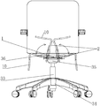
- FIG. 1 is a schematic diagram of the three-dimensional structure of the conversion between the sitting state and the standing state in Embodiment 1 of the present invention
- FIG. 2 is a schematic diagram of the three-dimensional structure of the main support body and the side support body in the sitting state of the present invention in the first embodiment
- FIG. 3 is a schematic diagram of the three-dimensional structure of the rotational connection between the rear end of the main support body and the side support body in Embodiment 1 of the present invention
- Figure 4 is a top view of the standing chair in a sitting state in the first embodiment of the present invention.
- FIG. 5 is a schematic diagram 1 of the three-dimensional structure of the main support body and the side support body in the sitting state of the present invention in the second embodiment;
- FIG. 6 is a schematic diagram 1 of the three-dimensional structure of the main support body and the side support body in the stance state of the present invention in the second embodiment;
- FIG. 7 is a second schematic diagram of the three-dimensional structure of the main support body and the side support body in the stance state of the present invention in the second embodiment;
- FIG 8 is the second three-dimensional structural schematic diagram of the main support body and the side support body in the sitting state of the present invention in the second embodiment;
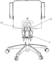
- FIG. 9 is a schematic diagram of a three-dimensional structure of a standing chair in a sitting state in Embodiment 3 of the present invention.
- Figure 10 is a top view of the standing chair in a sitting state in the third embodiment of the present invention.
- Figure 11 is a front view of the standing chair in a sitting state in the third embodiment of the present invention.
- FIG. 12 is a schematic diagram of the three-dimensional structure of the standing chair in the standing state in Embodiment 3 of the present invention.
- Figure 13 is a cross-sectional view in the direction C in Figure 18;
- FIG. 14 is a schematic diagram of the three-dimensional structure of the conversion between the sitting state and the standing state in Embodiment 3 of the present invention.
- 15 is a schematic diagram of the three-dimensional structure of the position-limiting member and the locking assembly in the sitting state in the fourth embodiment of the present invention.
- FIG. 16 is a schematic diagram of the three-dimensional structure of the restraint member and the locking assembly in the stance state of the present invention in Embodiment 4;
- Figure 17 is a rear view of the main and side support bodies and the lock pin cooperated with the limit disk in the sitting state in the fourth embodiment of the present invention.
- Figure 18 is a front view of the main and side support bodies and the lock pin and the limit plate in the sitting state in the fourth embodiment of the present invention.
- Figure 19 is a rear view of the main and side support bodies and the lock pin and the limit plate in the standing state in the fourth embodiment of the present invention.
- Fig. 20 is a front view of the main and side support bodies and the locking pin and the stop disc in the standing state in the fourth embodiment of the present invention.
- Figure 21 is a bottom view of the locking assembly in Embodiment 4 of the present invention.
- Figure 22 is a side view of the locking assembly in Embodiment 4 of the present invention.
- FIG. 23 is a schematic diagram of a three-dimensional structure of an elastic card in Embodiment 4 of the present invention.
- FIG. 25 is a schematic diagram of the conversion of sitting and standing postures in Embodiment 4 of the present invention.
- 26 is a schematic diagram of the three-dimensional structure of the main and side supports in a sitting state in Embodiment 4 of the present invention.
- FIG. 27 is a schematic diagram of the three-dimensional structure of the main and side supports in the standing state in Embodiment 4 of the present invention.
- Fig. 28 is a partial enlarged view of part D in Fig. 21;
- Figure 29 is a partial enlarged view of part E in Figure 28;
- Figure 30 is a rear view of the main and side supports and the gear set in a sitting state of the present invention in Embodiment 5;
- Figure 31 is a schematic diagram of the three-dimensional structure of the transmission member and the locking pin in embodiment 5 of the present invention.
- Figure 32 is a rear view of the coupling of the transmission member and the locking pin in Embodiment 5 of the present invention.
- Figure 33 is a rear view of the transmission assembly in Embodiment 5 of the present invention.
- Figure 34 is a three-dimensional schematic diagram of the present invention with a first-stage gear and a transmission element on the long shaft in Embodiment 5;
- FIG. 36 is a schematic diagram of the three-dimensional structure of the support seat in the flat posture in Embodiment 6 of the present invention.
- FIG. 37 is a schematic diagram of the three-dimensional structure of the support base in an upright posture in Embodiment 6 of the present invention.
- the reference signs are: main support body 1; side support body 2; inner part 3; outer part 4; rotating shaft seat 5; rotating shaft 7; mounting plate 8; auxiliary support body 9; 11; lifting air rod 33; five-star foot 34; seat chassis 35; connecting rod 36; outer contour line 37; arched body 40; sponge extension 41; main support sponge 42; side support sponge 43; limiter 53 ; Locking component 54; Limiting plate 57; Lock pin 58; Sitting position locking groove 59; Standing position locking groove 510; Seat block 511; Base 512; Rotating shaft seat plate 513; Base plate seat 514; Connecting plate 515; Mounting seat 517; Piece 518; connecting part 519; vertical part 520; guide hole 521; control cable assembly 522; U-shaped groove 523; ring groove 524; elastic card 525; gasket 526; lock pin reset spring 527; elastic clamping arm 528; Gear set 74; mounting plate 75; primary gear 76; driven gear 77; rotating shaft hole 78; rotating shaft 79; long shaft 710
- the term "at least one” refers to one or more than one unless specifically defined otherwise.
- the terms “first”, “second”, “third”, etc. are only used for descriptive purposes, and cannot be understood as indicating or implying relative importance.
- the present invention provides a sitting and standing chair, comprising: a main support 1 and side supports 2 symmetrically arranged on both sides of the main support 1, and the side supports 2 can be opposite to the main support 1. Relative rotation occurs.
- the main support 1 is a seat plate, and a seat support assembly is provided under the main support 1.
- the seat support assembly includes a lifting air rod 33 and a five-star foot 34 and the seat chassis 35, the lifting air rod 33 is connected between the five-star foot 34 and the seat chassis 35, the main support body 1 is connected to the upper end of the seat chassis 35, and the main support body 1 can be raised and lowered by the lifting air rod 33.
- the side support 2 is a plate-shaped body. Along the width direction, the side support 2 has an inner part 3 close to the main support 1 and an outer part 4 away from the main support 1.
- the outer part 4 is the outer side of the side support 2.
- Partial margin refers to the outer partial marginal area of the side support 2 in a broad sense, and generally refers to the part that can support the human body to sit in the standing posture.
- the sitting and standing chair has a sitting state and a standing state; in the sitting state: the main support body 1 and the side support body 2 are in a flat posture, forming a seat surface for the user to sit flat, the seat surface can also be flat It can be an ergonomic curved surface; when transitioning from a sitting state to a standing state, turn the side supports 2 on both sides up to an upright position, which does not necessarily limit the side supports 2 to remain strictly perpendicular to the horizontal plane , More refers to the fact that after the side support 2 is turned up, the outer part 4 of the side support 2 can be at a higher height. During the upturning process, the main support 1 can remain fixed.
- the side support 2 In the upright posture, it can meet the height use requirements of most people in the standing posture; and when the side supports are in the upright posture, it cannot meet the sitting requirements of the human body in the standing posture, such as the user is too high Or if it is too short, the height of the main support 1 can be controlled by lifting the air rod 33, so as to meet the needs of the user.
- the inner part 3 of the side support body 2 can be connected to the left and right sides of the main support body 1 by hinge rotation, but at this time, in order to satisfy that the side support body 2 has a reasonable height after being turned up, and the two side support bodies 2 can be brought together
- the width of the main support 1 is usually reduced, which may make the contact surface between the main support 1 and the seat chassis 35 smaller and difficult to configure; in order to solve this problem, the side support The rotation connection of 2 is set at the inner side of the front and rear ends of the main support 1, so that the main support 1 and the seat chassis 35 under the main support 1 can maintain a sufficient contact area, and the side support The body 2 has a reasonable height after being turned upwards, and at the same time, the two side support bodies 2 can be as close as possible to facilitate the user to ride.
- the above-mentioned rotation connection is realized as follows: the side support body 2 is welded with a connecting rod 36 at the front and rear. 7 Rotate the connection.
- the above paragraphs describe the core idea of the present invention.
- the purpose of sitting-to-stand conversion is achieved through the upward turning of the side support 2; in actual use, in order to improve the comfort of use and the consideration of the sitting posture of the human body in the standing state, Optimize the design of the side support body 2.
- the outer part 4 extends downwards out of the standing support part 10, which is in the shape of a hanging ear and has a curved surface.
- the side support body 2 and the standing support part 10 are integrally formed; when the side support body 2 is turned up and fixed, the two standing support parts 10 are close together, and the standing support part 10 hangs down at the same time.
- the state is converted to a substantially horizontal state that is good for supporting the human body.
- the two standing support parts 10 form a saddle with a narrower width than the seat surface in the sitting state for the user to sit on.
- the side support body 2 needs to be limited in the sitting and standing states. There can be many such limiting methods.
- the following examples are as follows:
- the front and rear ends of the main support body 1 are provided with a rotating shaft seat 5, the side support body 2 and the rotating shaft seat 5 are connected by a connecting rod 36, and the same rotating shaft is penetrated on the rotating shaft seat 5 and the connecting rod 36 7.
- One end of the connecting rod 36 is provided with a mounting plate 8, which is connected and fixed to the lower surface of the side support 2 close to the inner part 3; the side support 2 drives the mounting plate 8 to rotate synchronously, so that the connecting rod 36 rotates around the shaft 7 .
- An auxiliary support 9 extends from the front of the side support 2 toward the middle of the main support 1.
- the auxiliary support 9 is used to increase the depth of the seat. In a sitting state, the side support 2 and the auxiliary support are viewed from above.
- the bodies 9 together form an L-shaped plate, and the outer contour line 37 of the formed L-shaped plate is curved, which makes the side support body 2 in an upright posture, making it easier for people to ride up;
- An auxiliary support 9 extends from the rear of the support 2.
- the auxiliary support 9 can be co-extended from the front and rear of the side support 2, so that the side support 2 and the auxiliary support 9 together form a U-shaped plate; whether it is a U-shaped plate or an L-shaped plate , It depends on the overall arrangement of the seat.
- the rotation of the side support 2 is controlled by the stop mechanism 11 to lock the side support 2 in the flat or upright position; the specific structure of the stop mechanism 11 is described in detail in the fourth embodiment.
- the main support body 1 and the side support body 2 are in a flat posture, forming a seat surface for the user to sit flat, the standing support portion 10 hangs on the left and right sides of the seat surface, and the side support body 2 is
- the limit mechanism 11 is locked and cannot be rotated; standing position: the limit mechanism 11 unlocks the side support body 2, and the side support body 2 rotates relative to the main support body 1 and turns the side support body 2 up to an upright position, while the side support body
- the outer part 4 of 2 is raised, the two standing support parts 10 are close to and form a saddle with the auxiliary support 9 to cater for the user to sit or lean on, and the side support 2 is locked by the stop mechanism 11 here;
- the lifting air rod 33 is controlled to raise or lower the main support body 1 and the side support body 2 in an upright posture to achieve a proper standing and sitting height.
- Embodiment 2 The difference between this embodiment and embodiment 1 is that in the standing state, considering the user’s sitting posture and meeting the user’s riding needs, a new design is made for the standing support part 10 .
- the outer part 4 of the side support body 2 extends downward and toward the inner part 3 of the side support body 2 to extend out of the standing posture support part 10, the standing posture support part 10 and the side support body 2
- the included angle is 10°-30°, so that in the sitting state, the standing support portion 10 does not appear to have a strong downward abrupt feeling.
- the two side supports 2 are in an upright position and are close to each other, the two The upper ends of the two side supports 2 are close to or close to each other, and the two standing support portions 10 and the upper ends of the two side supports 2 together form an arch body 40 that is convenient for the user to ride.
- the arch body 40 is in the shape of a saddle. It is convenient for users to ride and sit up, and at the same time, it has an ergonomic effect.
- Embodiment 3 The difference between this embodiment and Embodiments 1 and 2 is that in the standing state, considering the user’s sitting posture and meeting the user’s riding needs, the standing support part 10 has been updated. design.
- the above-mentioned stance supporting portion 10 and the side support body 2 are made of materials with strong plasticity.
- plasticity refers to the ability of the material to be bent and able to maintain this deformation, for example, but It is not limited to plastic; when the side support 2 is made of materials with poor plasticity, such as wood board, in order to ensure the comfort of use in the sitting state, the main support sponge 42 is laid on the upper surface of the main support, and the upper surface of the side support 2 is laid The side support sponge 43, while the sponge straddles the outer part 4 of the side support 2 and extends toward the inner part 3 of the side support 2, forming a sponge extension 41.
- the width of the sponge extension 41 can be determined according to actual conditions.
- the purpose is to make the user’s inner thigh contact with the sponge extension 41 after the user rides up in the standing posture, thereby improving the comfort of sitting; when the two side supports 2 are in an upright posture, the two side supports 2 The upper ends are close to or close to each other, and the two sponge extension bodies 41 and the upper ends of the side supports 2 together form a flexible support for the user to sit on.
- Embodiment 4 This embodiment describes in detail the limiting mechanism in Embodiment 1. It should be noted that the appearance of the seat in this embodiment is different from that in Embodiment 1, but the technical features are the same, such as the main support body 1 and the side supports The appearance of the body 2 has been changed; and the limit disk 57 can function as the connecting rod 36 in the first embodiment, so the connecting rod 36 can be omitted in this embodiment.
- the limiting mechanism of this embodiment includes a main support 1, a side support 2, a limiting member 53 and a locking assembly 54.
- the sitting and standing chair realizes the conversion of sitting and standing posture as follows: the main support body 1 is configured as the main body support of the seat surface of the sitting and standing chair; The supporting body 1 is rotatably connected; in the width direction, the side supporting body 2 has an inner part close to the main supporting body 1 and an outer part away from the main supporting body 1.
- the sitting and standing chair has a sitting state and a standing state; in the sitting state: the main support body 1 and the side support body 2 are in a flat posture, that is, the side support body 2 is flat. Spread on both sides of the main support body 1 to form a seat surface for the user to sit flat; standing position: the side support body 2 rotates relative to the main support body 1 and the side support body 2 is turned up to an upright position, and two The outer part of the side support 2 is raised and approached to a set distance to cater for the user to sit or lean on.
- the limiting member 53 as shown in Figures 15-20 is a disk-shaped body, called a limiting disk 57, the limiting disk 57 is provided with two locking grooves, and the limiting disk 57 is arranged on the side support 2;
- the locking assembly 54 is installed on the main support 1, and the locking assembly 54 includes a lock pin 58 that is selectively movable; when the side support 2 is turned over to a preset position relative to the main support 1, the lock pin 58 is locked with the corresponding lock pin 58.
- the groove lock cooperates to limit and lock the limit disk 57.
- An auxiliary support 9 extends from the front or rear of the side support 2 toward the middle of the main support 1.
- the auxiliary support 9 and the side support The body 2 surrounds the main support body 1; the auxiliary support body 9 is a part of the side support body 2, and the limit disc 57 is installed on the side support body 2; the lock pin 58 moves in the seat depth direction, and The limit disc 57 is arranged to face the moving direction of the lock pin 58.
- limit disks 57 There are a total of four limit disks 57, two at the front and rear.
- the limit disks 57 are respectively connected and fixed on the auxiliary support body 9 extended from the two side supports 2 and are rotatably connected with the main support body 1 through a rotating shaft;
- the position disk 57 is provided with a lock pin 58 correspondingly, and the lock pin 58 can be inserted into or withdrawn from the locking groove to lock or unlock the limit disk 57;
- the two locking grooves are the sitting position locking groove 59 and the standing position locking groove 510.
- the side supports 2 are laid flat on both sides of the main support 1, and the sitting locking groove 59 on the limit plate 57 is aligned with the lock pin 58.
- the lock pin 58 moves in the seat depth direction and is inserted into the sitting position lock In the groove 59, the sitting chair can be locked in the sitting state; in the standing state, the side support 2 is turned up to the upright position, and the stance locking groove 510 on the limit plate 57 is aligned with the locking pin 58, and the lock is now locked
- the pin 58 moves along the seat depth direction and inserts it into the standing position locking groove 510 to lock the sitting and standing chair in the standing position; when the sitting and standing chair needs to switch between sitting and standing positions, the locking pin 58 moves in the seat depth direction and moves from Withdraw from the locking groove, so that the side support 2 can rotate relative to the main support 1 to switch the desired sitting and standing chair state.
- the front and rear ends of the main support 1 extend downwards from a seat block 511.
- the seat block 511 is provided with a base 512.
- the base 512 includes a shaft seat plate 513 attached to the front or rear face of the seat block 511 and attached to the bottom surface of the seat block 511.
- the closed bottom plate seat 514; the limit disk 57 and the rotating shaft seat plate 513 are rotatably connected by the rotating shaft;
- the limit disk 57 is a semi-circular disk, and a connecting plate provided with a threaded hole extends in the direction of the limit disk 57 away from the arc 515, the connecting plate 515 and the limiting disk 57 are bent, the limiting disk 57 and the connecting plate 515 are integrally formed, and the limiting disk 57 is connected and fixed to the bottom surface of the auxiliary support body 9 through the connecting plate 515.
- the limit disc 57 is arranged on the bottom surface of the auxiliary support body 9, and the rotation point of the limit disc 57 and the main support body 1 is located below the main support body 1, that is, on the shaft seat plate 513 of the seat block 511. 57 is hidden under the seat surface, so that in the sitting state, the side support body 2 can be kept on the same level as the main support body 1, and the limit disk 57 is not obtrusive.
- the lock pin 58 performs the limit lock on the limit disk 57, and the lock pin 58 needs to move along the seat depth direction, specifically:
- the locking assembly 54 includes a mounting seat 517 and a paddle 518.
- the mounting seat 517 is disposed on the bottom plate seat 514, and the mounting seat 517 includes a connecting portion connected to the bottom plate seat 514. 519 and two vertical parts 520 arranged in parallel with the limit disk 57, and the vertical part 520 is integrally formed with the connecting part 519, the vertical part 520 is provided with a guide hole 521, and the lock pin 58 is arranged in the guide hole 521 Middle;
- the paddle 518 is vertically arranged and rotatably connected to the connecting portion 519, one end of the paddle 518 is connected to the lock pin 58, and the other end is connected with a control assembly, the control assembly controls the paddle 518 to rotate relative to the mounting seat 517, while dialing
- the piece 518 drives the lock pin 58 to move;
- the control component is a control cable component 522.
- the paddle 518 is connected to the lock pin 58 between the vertical portions 520.
- a U-shaped groove 523 is opened at one end of the paddle 518 connected to the lock pin 58.
- the U-shaped groove 523 connects the lock pin 58 is half-enclosed, the lock pin 58 in front of the U-shaped groove 523 is cut radially inward at a ring groove 524, and an elastic card 525 is provided on the ring groove 524; the paddle 518 drives the lock pin 58 to move by pushing the elastic card 525
- a gasket 526 is provided between the elastic card 525 and the paddle 518, and the gasket 526 is sleeved on the lock pin 58; a locking pin reset spring 527 is also sleeved on the lock pin 58 in front of the elastic card 525 to reset the lock pin.
- the spring 527 abuts on the vertical portion 520 of the mounting seat 517 and acts on the elastic card 525.
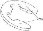
- the elastic card 525 is a ring-shaped body with an opening on the circumference.
- the ring-shaped body has two symmetrically arranged elastic clamping arms 528. It protrudes from the outer peripheral surface of the lock pin 58.
- the paddle 518 pushes the elastic card 525 to move the lock pin 58 in the direction of the guide hole 521, that is, in the seat depth direction, and the lock pin 58 is inserted to lock In the groove, the elastic card 525 compresses the lock pin return spring 527 at the same time; when the control cable assembly 522 is released, the lock pin return spring 527 rebounds to push the elastic card 525 so that the lock pin 58 exits the locking groove and returns to the initial position, while the paddle 518 Also rotate back to the initial position.
- a linkage mechanism is required. Including transmission components; when the sitting chair switches between the sitting state and the standing state, the transmission components act on the side supports 2 and cause the two side supports 2 to rotate synchronously; as shown in Figure 30-34, stand opposite
- the linkage mechanism of the chair is introduced as follows:
- the side support body 2 has a C-shape as a whole and surrounds the main support body 1; the transmission assembly is arranged between the two side supports 2 and the transmission assembly is located at the rear of the main support body 1. It is configured to transmit the rotating torque of the side support body 2 to the other side support body 2 when the one side support body 2 rotates and make the two side supports 2 rotate synchronously; there are many ways to realize the transmission assembly.
- the embodiment specifically introduces the transmission assembly of the gear transmission structure.
- the transmission assembly adopts a gear transmission structure, that is, the transmission assembly includes a gear set 74.
- the gear set 74 is arranged on the main support 1 through a mounting plate 75.
- the gear set 74 includes a side support
- the first-stage gear 76 of the body 2 rotates synchronously and the driven gear 77 that is meshed and arranged between the two first-stage gears 76; there are two driven gears 77 in total and mesh with each other; the mounting plate 75 and the main support 1
- the connection is fixed, the mounting plate 75 is provided with a rotating shaft hole 78, and the first-stage gear 76 and the driven gear 77 are both arranged on the mounting plate 75 through the rotating shaft 79 and are rotatably connected with the main support 1;
- the plate 75 separates the gear from the main support 1.
- the side support body 2 and the main support body 1 are rotatably connected by a long shaft 710.
- the long shaft 710 penetrates the main support body 1 back and forth and is inserted into the side support body 2.
- the primary gear 76 and the side support body 2 are both penetrated in The long axis 710.
- the transmission assembly further includes a transmission member 711, which is respectively fixedly connected to the primary gear 76 and the side support 2; specifically:
- the transmission member 711 is roughly a strip-shaped body, and the transmission member 711 penetrates the long shaft 710; the transmission member 711 includes a fixed portion 712 connected and fixed with the side support 2 and a limiting tip 713; In the width direction, the fixing portion 712 is located outside the long shaft 710, the fixing portion 712 is a rectangular plate-shaped body, and the lower end of the fixing portion 712 is bent to form an L-shaped plate-shaped body.
- the fixing portion 712 of the spool at the same time plays the role of connecting with the supporting side support 2; in the width direction of the seat, the limiting tip 713 is located on the inner side of the long axis 710, and the limiting tip 713 is a hook-shaped plate-shaped body , Its tip faces the inner side of the long shaft 710; the linkage mechanism also includes a locking pin 714 that is relatively fixed to the main support 1 and cooperates with the limiting tip 713, the locking pin 714 is arranged above the limiting tip 713; The pin 714 is configured to limit the limit tip 713 when it rotates to a preset position; that is, when the side support 2 is in a flat posture, the limit tip 713 abuts against the locking pin 714 above it, thereby acting Until the side support body 2 is prevented from turning downward.
- the first gear 76 has a transmission lug 715 extending outward in the radial direction.
- the transmission lug 715 is located between the mounting plate 75 and the fixing portion 712.
- the transmission member 711 and the transmission lug 715 are connected by a pin shaft. .
- the side support body 2 on one side rotates around the long shaft 710, it drives the transmission member 711 fixedly connected to it to rotate in the same direction.
- the fixed member drives the primary gear 76 to rotate in the same direction, because the two driven gears 77 mesh with each other.
- the supporting body 2 rotates in the reverse direction, so that the side supporting bodies 2 on both sides are turned up or down synchronously.
- the main support body 1 is always in a flat position, and a hollow support seat 90 is provided below the main support body 1.
- the support seat 90 is configured to connect to the seat support assembly, and the support seat The middle part of 90 sinks, the front and rear ends of the support base 90 are upturned, the main support body 1 is supported by the front and rear ends of the support base 90, and the side support body 1 is rotatably connected with the main support body 1; of course, the side support body 1 is also It can optionally be connected to the support base 90 in rotation.
- the main support 1 itself is a base, that is, a support seat.
- the main support 1 can be arranged under the side supports 2, and the main support 1 is in a hollow shape.
- the middle part of the main support body 1 sinks, the front and rear ends are upturned, and the side support body 2 is rotatably connected to the front and rear ends of the main support body 1, which is conducive to the simple and smooth design of the seat; the side support body 2 is arranged symmetrically, one of the two A straight slit 81 is formed between it, and an outer cover can be provided to cover the slit 81.
- the appearance of the seat is no different from that of a normal seat; uncover the outer cover and turn the side support 2 to an upright position to make the sitting stand
- the chair is switched to the standing state for the user to ride or lean on; the sitting and standing chair thus arranged has a simple structure and a simple appearance, which is more aesthetically pleasing.
Abstract
A sit-stand chair, comprising a main support body (1), and side support bodies (2) symmetrically arranged on the left and right sides of the main support body (1). The side support bodies (2) are configured to rotate around the main support body (1). In the width direction, each side support body (2) has an inner side portion (3) close to the main support body (1) and an outer side portion (4) distant from the main support body (1). The sit-stand chair has a sitting posture state and a standing posture state. In the sitting posture state, both the main support body (1) and the side support bodies (2) are in a flat posture to form a seat surface allowing a user to sit down; in the standing posture state, the side support bodies (2) are rotated with respect to the main support body (1) and are turned upwards to an upright posture, and the outer side portions (4) of the side support bodies (2) are raised to cater for the user to sit or lean on. Compared with the prior art, the sit-stand chair can switch between the sitting posture and the standing posture by laying the side support bodies (2) flat or turning same upwards, and is simple in structure and easy to operate; moreover, the basic height is increased when the side support bodies (2) are turned upwards, thereby facilitating the user in sitting or leaning in the standing posture state.
Description
本发明涉及座椅领域,特别涉及一种坐站椅。The invention relates to the field of seats, in particular to a sitting and standing chair.
座具在现代人学习和工作中广泛使用,对于大多数办公椅或学习椅而言,只具备坐的功能;从生理学角度来说,一个人站久了腿部负荷过重使人易感到劳累;而坐久了人也会感到难受或疲劳,同时还会因为脑供血不足、全身重量压在脊椎底端等引发诸如记忆力减退、头痛头晕、腰椎颈椎等各种疾病,对身体不利。久坐对身体不利已有许多研究和报道,一个人站久了就希望能坐坐,而坐久了又希望能够站站。Seats are widely used in modern people's study and work. For most office chairs or study chairs, they only have the function of sitting; from a physiological point of view, a person standing for a long time with heavy legs makes people feel tired easily ; People who sit for a long time will also feel uncomfortable or tired. At the same time, they will cause various diseases such as memory loss, headache, dizziness, lumbar spine and cervical spine due to insufficient blood supply to the brain and weight of the whole body on the bottom of the spine, which is harmful to the body. There have been many studies and reports that sitting for a long time is bad for the body. After standing for a long time, a person hopes to be able to sit, and after sitting for a long time, he hopes to be able to stand.
在久坐的人中间,似乎办公室白领和在校学习的学生坐的时间最长,他们几乎整小时整天地坐着工作或者学习,很难进行姿势的调节,不仅人很容易产生疲劳,而且身体容易受到影响。解决该问题的方法是最好让人的“坐”和“站”能够交替进行。Among sedentary people, it seems that office white-collar workers and school-student students spend the longest time sitting. They sit for almost all hours to work or study. It is difficult to adjust their postures. Not only people are prone to fatigue, but also The body is easily affected. The solution to this problem is that it is best for people to alternate between "sit" and "stand".
CN201410106815.8的中国发明专利公开了一种可坐可站的椅子,该椅子是通过左翻板10、右翻板11和横梁9的配合来实现坐站之间的转换,且左翻板10、右翻板11二者不同步翻转,因此使用价值不高;此外,左翻板10、右翻板11不能够随椅座上、下移动而产生变化,使用体验感较差;再有,该椅子的左翻板10、右翻板11翻转调节不够简单、方便。The Chinese invention patent of CN201410106815.8 discloses a chair capable of sitting and standing. The chair realizes the conversion between sitting and standing through the cooperation of the left flap 10, the right flap 11 and the cross beam 9, and the left flap 10 , The right flap 11 is not synchronized flipped, so the use value is not high; In addition, the left flap 10 and the right flap 11 cannot change with the up and down movement of the chair seat, and the experience of use is poor; moreover, The turning adjustment of the left flap 10 and the right flap 11 of the chair is not simple and convenient.
CN201910970699.7的中国发明专利公开了一种椅具单元及椅具,包括底座,具有动轨与静轨的滑轨组件,静轨与底座固定连接;座支撑件,座支撑件包括中座及侧座,中座被配置为总是保持在大致水平状态或与水平面呈锐角,中座 与动轨相对固定;侧座与中座相铰接;动轨相连并随动轨一起上下移动的背支撑件,响应于中座的升降移动的联动机构,并且联动机构作用于侧座使其相对于中座翻转;该椅具单元具有两个状态:平坐状态与站姿状态,且座椅变换机构可以在两个状态自由转换间;该发明中的椅具坐站姿的转换是靠椅背带动中座同步上升,两边的侧座随之向下翻转,所以椅背后方需要设置滑轨来对椅背进行导引,并且还需要配备一个气杆来对椅背进行驱动,整体提高了座椅的重量,增加了成本。The Chinese invention patent of CN201910970699.7 discloses a chair unit and a chair, including a base, a slide rail assembly with a moving rail and a static rail, the static rail and the base are fixedly connected; a seat support, the seat support includes a middle seat and The side seat, the middle seat is configured to always remain roughly horizontal or at an acute angle to the horizontal plane, the middle seat and the moving rail are relatively fixed; the side seat and the middle seat are hinged; the moving rail is connected to the back support that moves up and down with the moving rail Piece, a linkage mechanism that responds to the lifting movement of the middle seat, and the linkage mechanism acts on the side seat to make it flip relative to the middle seat; the chair unit has two states: a flat sitting state and a standing state, and a seat changing mechanism It can be freely switched between the two states; the conversion of the chair in the present invention is that the seat back drives the middle seat to rise synchronously, and the side seats on both sides turn down accordingly, so a slide rail needs to be set on the back of the chair. The seat back is guided, and an air rod is also required to drive the seat back, which increases the weight of the seat as a whole and increases the cost.
发明内容Summary of the invention
为了解决上述的技术问题,本发明提供了一种坐站椅,其关键在于主支撑体左右两侧设置了可以转动的侧支撑体;侧支撑体处于平铺姿态时,坐站椅为坐姿状态,主、侧支撑体形成供使用者平坐的座位面;侧支撑体相对于主支撑体转动并使侧支撑体上翻至直立姿态,坐站椅为站姿状态同时侧支撑体的外侧部分升高以迎合使用者就坐或倚靠。In order to solve the above technical problems, the present invention provides a sitting chair, the key is that the left and right sides of the main support are provided with rotatable side supports; when the side supports are in a flat position, the sitting chair is in a sitting state , The main and side supports form the seat surface for the user to sit flat; the side supports rotate relative to the main support and turn the side supports up to an upright posture. The sitting chair is in a standing state and the outer part of the side support Elevated to cater for the user to sit or lean on.
本发明的技术方案是这样实现的:The technical scheme of the present invention is realized as follows:
一种坐站椅,包括:A standing chair, including:
主支撑体,配置为坐站椅座面的主体支撑;The main support body is configured as the main body support of the seat surface of the sitting and standing chair;
侧支撑体,对称设置在主支撑体的左右两侧,侧支撑体配置为绕主支撑体转动;沿宽度方向,侧支撑体具有靠近主支撑体的内侧部分以及远离主支撑体的外侧部分;The side supports are symmetrically arranged on the left and right sides of the main support, and the side supports are configured to rotate around the main support; along the width direction, the side supports have an inner part close to the main support and an outer part far away from the main support;
该坐站椅具有坐姿状态与站姿状态;在坐姿状态下:侧支撑体均处于平铺姿态,形成一个供使用者平坐的座位面;站姿状态:侧支撑体相对于主支撑体转动并使侧支撑体上翻至直立姿态,同时侧支撑体的外侧部分升高以迎合使用者就坐或倚靠。该坐站椅通过侧支撑体平铺与上翻的变动实现了坐姿与站姿的 切换,结构简单,操作方便,并且在侧支撑体上翻时增加了基础高度,有利于站姿状态下使用者骑坐或倚靠;该坐站椅的支撑腿部分可配备标准化的升降气杆机构,既能做到升降,又不需增加额外的成本。The sitting and standing chair has a sitting state and a standing state; in the sitting state: the side supports are in a flat position, forming a seat surface for the user to sit flat; standing state: the side supports rotate relative to the main support The side support body is turned up to an upright posture, and at the same time, the outer part of the side support body is raised to cater for the user to sit or lean on. The sitting and standing chair realizes the switch between sitting and standing postures through the flat and upturning of the side supports. The structure is simple and easy to operate. The height of the foundation is increased when the side supports are upturned, which is conducive to use in the standing state. The support leg part of the sitting chair can be equipped with a standardized lifting air rod mechanism, which can be lifted and lowered without additional cost.
作为优选,所述的侧支撑体的外侧部分向下延伸出站姿承托部;站姿承托部呈垂耳状,用以在站姿状态下承托使用者的就坐或倚靠。垂耳状的站姿承托部提高了该椅在站姿状态下使用的舒适性与体验感。Preferably, the outer part of the side support body extends downward to extend the standing position support part; the standing position support part is in the shape of a drop ear and is used to support the sitting or leaning of the user in the standing position. The ear-shaped standing support part improves the comfort and experience of using the chair in the standing state.
作为优选,两个侧支撑体均处于直立姿态时,两个站姿承托部相互靠近并共同构成一个平铺状态的支撑面以承托使用者。此时使用者可像骑自行车一样骑坐在站姿承托部上。Preferably, when the two side supports are in an upright posture, the two standing posture supporting parts are close to each other and jointly form a flat supporting surface to support the user. At this time, the user can ride on the standing support part like riding a bicycle.
作为优选,侧支撑体的外侧部分向下并朝向侧支撑体的内侧部分方向延伸出站姿承托部,站姿承托部与侧支撑体之间的夹角为锐角。站姿承托部提高了该椅在站姿状态下使用的体验感,并且站姿承托部与侧支撑体之间的夹角小,更加适合使用者在站姿状态下倚靠。Preferably, the outer part of the side support body extends downward and toward the inner part of the side support body to extend out of the stance support part, and the angle between the stance support part and the side support is an acute angle. The standing support part improves the experience of using the chair in the standing state, and the angle between the standing support part and the side support is small, which is more suitable for the user to lean in the standing state.
作为优选,两个侧支撑体均处于直立姿态时,两个侧支撑体上端趋近或相贴,两个站姿承托部与两个侧支撑体上端共同构成一个利于使用者骑坐的拱形体。此时使用者可将大腿置于翻起的支撑座两侧并跨坐或者骑坐在拱形体上。Preferably, when the two side supports are in an upright posture, the upper ends of the two side supports approach or touch each other, and the two standing support portions and the upper ends of the two side supports together form an arch that is convenient for the user to ride. Physique. At this time, the user can place the thighs on both sides of the turned-up support seat and straddle or ride on the arch.
作为优选,所述的侧支撑体与站姿承托部为一体成型的板状体。一体成型的板状体成本低且有足够的支撑强度。Preferably, the side support body and the stance supporting portion are integrally formed as a plate-shaped body. The integrally formed plate-shaped body has low cost and sufficient supporting strength.
作为优选,在侧支撑体表面上包覆有海绵,海绵从侧支撑体上表面跨过外侧部分并延至侧支撑体的下表面,从而使侧支撑体外侧部分处形成在站姿状态下的柔性承托部。柔性承托部提高了该椅在坐姿状态与站姿状态下使用的舒适性。Preferably, the surface of the side support body is covered with sponge, and the sponge crosses the outer part from the upper surface of the side support body and extends to the lower surface of the side support body, so that the outer part of the side support body is flexible in a standing posture. Supporting Department. The flexible supporting part improves the comfort of the chair in sitting and standing states.
作为优选,两个侧支撑体均处于直立姿态时,两个侧支撑体上端趋近或相 贴,两个柔性承托部与侧支撑体上端共同构成供使用者骑坐的支撑体。此时使用者骑坐在支撑体上时,大腿内侧接触柔性承托部,舒适性更好。Preferably, when the two side supports are in an upright posture, the upper ends of the two side supports approach or abut together, and the two flexible supporting parts and the upper ends of the side supports together form a support for the user to ride on. At this time, when the user rides on the support body, the inner thigh touches the flexible supporting part, and the comfort is better.
作为优选,在坐姿状态与站姿状态下,主支撑体始终处于平铺状态;在坐姿状态下,主支撑体与侧支撑体共同形成一个供使用者平坐的座位面;所述的侧支撑体的转动连接位置位于主支撑体前后两端各自靠内侧的位置。两个侧支撑体与主支撑体的转动连接处靠得较近,一方面使两个侧支撑体上翻后,两者的间距小,方便使用者骑坐,并且体验感更好;另一方面,侧支撑体较窄,但转动连接处于内侧部分间距较大,使侧支撑体上翻后的高度有所增加,同时又能减少成本。Preferably, in the sitting state and the standing state, the main support is always in a flat state; in the sitting state, the main support and the side support jointly form a seat surface for the user to sit flat; the side support The rotating connection position of the body is located at the inner side of the front and rear ends of the main support body. The rotation connection between the two side supports and the main support is closer. On the one hand, after the two side supports are turned up, the distance between the two is small, which is convenient for the user to ride and has a better experience; on the other hand, On the one hand, the side support body is narrow, but the distance between the inner part of the rotating connection is larger, which increases the height of the side support body after being turned up, and at the same time reduces the cost.
作为优选,所述的侧支撑体的前部或后部朝向主支撑体的中间延伸出辅助支撑体,在坐姿状态下,辅助支撑体与侧支撑体将主支撑体包围其中。辅助支撑体增加了该椅在坐姿状态下的座深和支撑面积,提升了座椅舒适度;同时又能遮挡侧支撑体与主支撑体的转动连接部分,提升了美观度。Preferably, an auxiliary support body extends from the front or rear part of the side support body toward the middle of the main support body. In the sitting state, the auxiliary support body and the side support body surround the main support body. The auxiliary support body increases the seat depth and support area of the chair in the sitting state, and improves the comfort of the seat; at the same time, it can shield the rotating connection part of the side support body and the main support body, and improve the aesthetics.
作为优选,在主支撑体下方设有挑空的支撑座,该支撑座配置为连接椅座支撑组件,该支撑座的中间部分下沉,支撑座的前后两端上翘,主支撑体由支撑座的前后两端支撑,侧支撑体与主支撑体或支撑座转动连接。Preferably, a hollow support seat is provided under the main support body, and the support seat is configured to be connected to the seat support assembly. The front and rear ends of the seat are supported, and the side support body is rotatably connected with the main support body or the support seat.
作为优选,还包括有将侧支撑体限定于平铺姿态或直立姿态的限位机构。通过限位机构使得支撑座能保持在平铺或直立姿态下,从而实现坐、站姿状态下座椅的稳定使用。Preferably, it also includes a limiting mechanism that limits the side support body to a flat posture or an upright posture. The limit mechanism enables the support seat to be kept in a flat or upright posture, so as to realize the stable use of the seat in the sitting and standing postures.
作为优选,限位机构包括限位件与锁定组件,限位件安装于主支撑体或侧支撑体的其中一个上,限位件具有至少两个锁定位;锁定组件安装在主支撑体或侧支撑体的另外一个上,所述锁定组件包括有选择性移动的锁销;侧支撑体处于平铺姿态或直立姿态时,锁销与相应的锁定位锁定配合,对限位件限位锁 定。为了能让主支撑体与侧支撑体之间锁定以保持坐站椅的坐姿状态或站姿状态,故配合使用限位件与锁定组件来实现,使锁销与相应的锁定位配合即可完成限位锁定,结构与操作简单,便于使用者切换坐站姿状态。Preferably, the limiting mechanism includes a limiting member and a locking component. The limiting member is installed on one of the main support or the side support. The limiting member has at least two locking positions; the locking component is installed on the main support or the side support. On the other one of the supporting bodies, the locking assembly includes a locking pin that is selectively movable; when the side supporting body is in a flat or upright position, the locking pin is locked and matched with a corresponding locking position to limit and lock the limit member. In order to lock the main support body and the side support body to maintain the sitting state or standing state of the sitting chair, it is achieved by using a stopper and a locking assembly, and the lock pin can be matched with the corresponding locking position. Limit locking, simple structure and operation, convenient for users to switch between sitting and standing postures.
作为优选,所述的限位件为盘状体,锁定位为开设在限位件上的锁定槽或锁定孔,所述的锁销沿座深方向移动。盘状体的限位件不会在随侧支撑体转动时卡住,保证了侧支撑体转动的顺畅;锁销沿座深方向移动,在锁销插入锁定槽或锁定孔时,可以锁定限位件转动,在锁销退出锁定槽或锁定孔时,又不会妨碍限位件和侧支撑体转动。Preferably, the limiting member is a disk-shaped body, the locking position is a locking groove or a locking hole opened on the limiting member, and the locking pin moves in the depth direction of the seat. The disc-shaped stopper will not get stuck when rotating with the side support, which ensures the smooth rotation of the side support; the lock pin moves along the depth of the seat, and when the lock pin is inserted into the locking groove or locking hole, the limit can be locked. When the positioning member rotates, when the lock pin exits the locking groove or the locking hole, the rotation of the limiting member and the side support body will not be hindered.
作为优选,所述的盘状体迎着锁销移动方向设置。盘状体如此设置使得盘状体上开设的多个锁定槽或锁定孔都可以与锁销进行配合。Preferably, the disc-shaped body is arranged to face the moving direction of the lock pin. The disc-shaped body is arranged in such a way that a plurality of locking grooves or locking holes opened on the disc-shaped body can be matched with the lock pin.
作为优选,所述的侧支撑体的前部或后部朝向主支撑体的中间延伸出辅助支撑体,侧支撑体平铺于主支撑体左右两侧时,辅助支撑体与侧支撑体将主支撑体包围其中;辅助支撑体配置为安装锁定组件或限位件。在辅助支撑体下方安装锁定组件或限位件使得两个侧支撑体与主支撑体的转动点靠近,一方面使两个侧支撑体上翻后,两者的间距小,方便使用者骑坐,并且体验感更好;另一方面,侧支撑体较窄,但转动连接处于内侧部分间距较大,使侧支撑体上翻后的高度有所增加,同时又能减少成本;并且设置在辅助支撑体下方的锁定锁紧或限位件不会显得突兀。Preferably, the front or rear of the side support extends toward the middle of the main support with an auxiliary support. When the side supports are flat on the left and right sides of the main support, the auxiliary support and the side support connect the The supporting body surrounds it; the auxiliary supporting body is configured to install a locking component or a limit piece. Install the locking assembly or limiter under the auxiliary support body to make the rotation points of the two side supports and the main support body close. , And the experience is better; on the other hand, the side supports are narrower, but the distance between the inner part of the rotating connection is larger, which increases the height of the side supports after turning up, and at the same time reduces the cost; and it is set in the auxiliary The locking or limiting member under the support body will not appear abrupt.
作为优选,所述的限位件与侧支撑体连接固定,限位件跟随侧支撑体转动;所述的锁定组件安装在主支撑体上。相较于锁定组件跟随侧支撑体转动来说,锁定组件上伴随的零部件太多,跟随侧支撑体转动不方便,而限位件随侧支撑体转动更加方便,在生产装配时也更简单。Preferably, the limiting member is connected and fixed with the side support body, and the limiting member rotates with the side support body; and the locking assembly is installed on the main support body. Compared with the rotation of the locking assembly following the side support body, there are too many components on the locking assembly, which is inconvenient to follow the side support body to rotate. It is more convenient for the stopper to rotate with the side support body, and it is simpler in production and assembly. .
作为优选,限位件通过转轴与主支撑体转动连接以实现侧支撑体的翻转。Preferably, the limiting member is rotatably connected with the main support body through a rotating shaft to realize the turning of the side support body.
作为优选,所述的锁定组件包括安装座与拨片,安装座安装在主支撑体或侧支撑体上,锁销穿设在安装座上;拨片与安装座转动连接,且拨片的一端与锁销连接,另一端连接有控制组件,控制组件控制拨片相对于安装座转动,同时拨片带动锁销移动。通过控制组件来控制拨片转动,再通过拨片的转动来驱动锁销的移动,从而实现多个锁销同时对相应的限位盘进行锁定或解锁。Preferably, the locking assembly includes a mounting seat and a paddle, the mounting seat is installed on the main support body or the side support body, and the lock pin passes through the mounting seat; the paddle is rotatably connected with the mounting seat, and one end of the paddle It is connected with the lock pin, and the other end is connected with a control assembly. The control assembly controls the paddle to rotate relative to the mounting seat, and the paddle drives the lock pin to move at the same time. The rotation of the paddle is controlled by the control component, and the movement of the lock pin is driven by the rotation of the paddle, so that multiple lock pins can lock or unlock the corresponding limit disk at the same time.
作为优选,拨片前方的锁销沿径向向内切削出一条环槽,在环槽上设有弹性卡片,拨片推动弹性卡片从而推动锁销移动。弹性卡片既实现了拨片带动锁销转动,又实现了对锁销在安装座内的限位。Preferably, the lock pin at the front of the paddle cuts a ring groove radially inward, and an elastic card is provided on the ring groove, and the paddle pushes the elastic card to push the lock pin to move. The elastic card not only realizes that the paddle drives the lock pin to rotate, but also realizes the limitation of the lock pin in the mounting seat.
作为优选,在弹性卡片前方设有复位弹簧,复位弹簧抵在安装座上并作用于弹性卡片。复位弹簧作用在弹性卡片上实现了锁销可以从锁定槽或锁定孔中退出。Preferably, a return spring is provided in front of the elastic card, and the return spring abuts on the mounting seat and acts on the elastic card. The return spring acts on the elastic card to realize that the lock pin can be withdrawn from the locking groove or the locking hole.
作为优选,所述的弹性卡片为圆周上设有开口的环状体,环状体具有两个对称设置的弹性卡接臂,弹性卡接臂卡入锁销的环槽中且整体外凸于锁销的外周面。弹性卡片卡入环槽使得弹性卡片被拨片推动时,弹性卡片能通过环槽带动锁销移动。Preferably, the elastic card is a ring-shaped body with an opening on the circumference, the ring-shaped body has two symmetrically arranged elastic clamping arms, the elastic clamping arms are clamped into the ring groove of the lock pin and the whole is projected outside The outer peripheral surface of the lock pin. The elastic card is locked into the ring groove so that when the elastic card is pushed by the pick, the elastic card can drive the lock pin to move through the ring groove.
作为优选,侧支撑体之间设有联动机构,使得当一块侧支撑体转动时,另一块侧支撑体同步转动。实现了座椅在切换坐、站姿状态时,两侧的侧支撑体同步翻转,简化使用者的操作;联动机构的设置又能减少锁定机构的数量,从而减少座椅的零配件,降低成本并节省装配时间,提高了生产效益。Preferably, a linkage mechanism is provided between the side supports, so that when one side support rotates, the other side support rotates synchronously. When the seat is switched between sitting and standing state, the side supports on both sides can be turned over synchronously, simplifying the operation of the user; the setting of the linkage mechanism can reduce the number of locking mechanisms, thereby reducing the parts of the seat and reducing the cost It also saves assembly time and improves production efficiency.
作为优选,所述的联动机构可以是齿轮传动机构。采用齿轮传动结构成本低、装配简单、提高生产装配的效率,并且更容易完成所需功能的实现。Preferably, the linkage mechanism may be a gear transmission mechanism. The gear transmission structure is low in cost, simple in assembly, improves the efficiency of production and assembly, and is easier to accomplish the realization of the required functions.
采用了上述技术方案的本发明的设计出发点、理念及有益效果是:The design starting point, concept and beneficial effects of the present invention adopting the above technical solutions are:
本发明提供了一种坐站椅,相比现有技术而言:The present invention provides a sitting and standing chair. Compared with the prior art:
1、从坐姿状态与站姿状态转换的实现效果和舒适性出发,实现坐站姿转换的关键所在是增加就坐的高度,在坐站姿转换的实现效果和使用舒适性之间进行调整,使两者达到平衡尤其重要;在现有技术中,只使用升降气杆实现坐站姿转换的技术,通常需要使用更长行程的气杆,甚至无法配备椅背,例如某些吧台椅;或者其他有做出结构创新的技术,在站姿状态下的座椅只能倚靠,缺失了就坐的功能,坐站姿转换的实现效果差且舒适性也大打折扣。1. Starting from the effect and comfort of the conversion between sitting and standing states, the key to achieving the conversion between sitting and standing is to increase the height of sitting, and adjust between the effect of sitting and standing conversion and the comfort of use, so that The balance between the two is particularly important; in the prior art, the technology that only uses the lifting air rod to realize the conversion between sitting and standing, usually requires the use of a longer stroke air rod, and even cannot be equipped with a chair back, such as some bar chairs; or other There are structural innovations. The seat in the standing position can only be leaned against, and the sitting function is missing. The effect of the sitting-to-stand conversion is poor and the comfort is greatly reduced.
本发明利用本来是作为椅面的侧支撑体进行向上翻转并使其锁定为直立姿态的方式,提高了站姿状态下基础就坐高度,而且此基础就坐高度是座椅本身通过机械机构可达到的就坐高度,已经可以适用部分人群;再利用座椅本身具备的升降气杆对就坐高度进行再次调节,以适应不同身高的人群对就坐高度的需求,坐站姿转换的实现效果完成度高,通过调节升降气杆达到适合不同身高使用者的就坐高度,提升了舒适性;同时本坐站椅本身带有椅背,并且由坐姿转换到站姿状态时,椅背保持不动,椅背的上半部分仍可以对使用者的腰背部进行支撑,既提升了舒适性又保证站姿状态下的使用安全性。The present invention utilizes the way that the side support body originally used as the seat surface is flipped upward and locked into an upright posture, thereby increasing the basic sitting height in the standing posture, and the basic sitting height is achievable by the seat itself through a mechanical mechanism The sitting height can already be applied to some people; the seat height can be adjusted again by the lifting air rod of the seat itself to meet the needs of people of different heights for the sitting height. The effect of sitting and standing conversion is high. Adjust the lifting air rod to reach the sitting height suitable for users of different heights, which improves the comfort; at the same time, the sitting and standing chair itself has a chair back, and when the sitting position is converted to the standing position, the back of the chair remains stationary, and the upper part of the chair back The half part can still support the user's waist and back, which not only improves the comfort but also ensures the safety of use in the standing state.
两块侧支撑体上翻后,外侧部分靠近形成突兀的山脊状体,考虑到使用舒适性,在侧支撑体外侧部分上延伸出站姿承托部或包覆海绵,可以通过不同的海绵定型设计以满足站姿状态下就坐的人体工学;类似自行车鞍座的站姿承托部能够让使用者以站姿骑坐上去,相对山脊状体而言,站姿承托部形成的支撑平面对使用者的压迫感小的多,提升了舒适性;而在站姿承托部与侧支撑体之间的夹角较小时,使用者既可骑坐又可从左右两侧的任一侧倚靠。After the two side supports are turned up, the outer part is close to form an abrupt ridge-like body. Considering the comfort of use, the standing support part or covering sponge is extended on the outer part of the side support, which can be shaped by different sponges Designed to meet the ergonomics of sitting in a standing position; the standing support part similar to a bicycle saddle allows the user to ride up in a standing position. Compared with the ridge-like body, the support plane formed by the standing support part is opposite The user’s pressure is much smaller, which improves comfort; and when the angle between the standing support part and the side support is small, the user can both ride and lean on either side of the left and right sides. .
2、从坐站姿转换的操作难易性出发,本坐站椅不需要将部件拆除再在调整高度后安装,只需简单地上翻侧支撑体再选择性地调节升降气杆就可以完成坐站姿转换。2. Starting from the ease of operation of the sitting-to-stand conversion, the sitting-standing chair does not need to be dismantled and then installed after adjusting the height. It can be completed by simply turning the side support body and selectively adjusting the lifting air rod. Standing change.
3、从成本出发,侧支撑体上翻后增加了就坐高度,只需配备一根升降气杆以更好地适应使用者的高度需求;该升降气杆不需要特制,也不需要用到多根升降气杆或者其他升降装置,常见座椅使用的标准化气杆即可满足需要,降低了材料成本,同时减轻了重量,降低了运输成本;此外,本坐站椅相对于普通座椅,为了提高使用便利性及安全性,可以再配备一个限位机构,尤其对站姿状态下的侧支撑体进行锁定。3. From the perspective of cost, the sitting height is increased after the side support body is turned up. It only needs to be equipped with a lifting air rod to better meet the height needs of the user; the lifting air rod does not need to be specially made, and it does not need to be used too much. With a lifting air rod or other lifting device, the standardized air rods used in common seats can meet the needs, reduce material costs, reduce weight, and reduce transportation costs; in addition, compared with ordinary seats, To improve the convenience and safety of use, it can be equipped with a limit mechanism, especially to lock the side support in the standing state.
4、本发明无需对站姿状态与坐姿状态各自配备不同的限位机构,只需要同一个限位机构就可以完成在站姿状态和坐姿状态下的锁定,结构简单且巧妙,精简了机构,节约了成本。4. The present invention does not need to be equipped with different limit mechanisms for the standing state and the sitting state. It only needs the same limit mechanism to complete the locking in the standing state and the sitting state. The structure is simple and ingenious, and the mechanism is simplified. Saved costs.
5、从座椅的结构出发,主支撑体可设置在侧支撑体下方,且主支撑体为挑空造型,利于座椅简洁流畅设计;侧支撑体左右对称设置,两者之间形成直线狭缝,在外可以罩设外罩遮盖狭缝,在坐姿状态下座部外观与普通座椅无异;将外罩揭开并翻转侧支撑体至直立姿态,即可使坐站椅切换到站姿状态,供使用者骑坐或倚靠;如此设置的坐站椅结构简单且外观简洁,更具有美感。5. Starting from the structure of the seat, the main support body can be set under the side support body, and the main support body has a hollow shape, which is conducive to the simple and smooth design of the seat; the side supports are arranged symmetrically, forming a straight line between the two A cover can be set outside to cover the slits. In the sitting state, the appearance of the seat is no different from that of a normal seat; uncover the cover and turn the side support to an upright position, and the sitting chair can be switched to a standing state. For the user to ride or lean on; the sitting and standing chair thus arranged has a simple structure and a concise appearance, which is more aesthetically pleasing.
图1为本发明在实施例1中坐姿状态与站姿状态转换的立体结构示意图;FIG. 1 is a schematic diagram of the three-dimensional structure of the conversion between the sitting state and the standing state in Embodiment 1 of the present invention;
图2为本发明在实施例1中坐姿状态下主支撑体与侧支撑体配合的立体结构示意图;2 is a schematic diagram of the three-dimensional structure of the main support body and the side support body in the sitting state of the present invention in the first embodiment;
图3为本发明在实施例1中主支撑体后端与侧支撑体转动连接的立体结构示意图;3 is a schematic diagram of the three-dimensional structure of the rotational connection between the rear end of the main support body and the side support body in Embodiment 1 of the present invention;
图4为本发明在实施例1中坐姿状态下坐站椅的俯视图;Figure 4 is a top view of the standing chair in a sitting state in the first embodiment of the present invention;
图5为本发明在实施例2中坐姿状态下主支撑体与侧支撑体配合的立体结构示意图一;5 is a schematic diagram 1 of the three-dimensional structure of the main support body and the side support body in the sitting state of the present invention in the second embodiment;
图6为本发明在实施例2中站姿状态下主支撑体与侧支撑体配合的立体结构示意图一;6 is a schematic diagram 1 of the three-dimensional structure of the main support body and the side support body in the stance state of the present invention in the second embodiment;
图7为本发明在实施例2中站姿状态下主支撑体与侧支撑体配合的立体结构示意图二;FIG. 7 is a second schematic diagram of the three-dimensional structure of the main support body and the side support body in the stance state of the present invention in the second embodiment;
图8为本发明在实施例2中坐姿状态下主支撑体与侧支撑体配合的立体结构示意图二;8 is the second three-dimensional structural schematic diagram of the main support body and the side support body in the sitting state of the present invention in the second embodiment;
图9为本发明在实施例3中坐姿状态下坐站椅的立体结构示意图;9 is a schematic diagram of a three-dimensional structure of a standing chair in a sitting state in Embodiment 3 of the present invention;
图10为本发明在实施例3中坐姿状态下坐站椅的俯视图;Figure 10 is a top view of the standing chair in a sitting state in the third embodiment of the present invention;
图11为本发明在实施例3中坐姿状态下坐站椅的前视图;Figure 11 is a front view of the standing chair in a sitting state in the third embodiment of the present invention;
图12为本发明在实施例3中站姿状态下坐站椅的立体结构示意图;FIG. 12 is a schematic diagram of the three-dimensional structure of the standing chair in the standing state in Embodiment 3 of the present invention;
图13为图18中在C方向上的剖视图;Figure 13 is a cross-sectional view in the direction C in Figure 18;
图14为本发明在实施例3中坐姿状态与站姿状态转换的立体结构示意图;14 is a schematic diagram of the three-dimensional structure of the conversion between the sitting state and the standing state in Embodiment 3 of the present invention;
图15为本发明在实施例4中坐姿状态下限位件与锁定组件配合的立体结构示意图;15 is a schematic diagram of the three-dimensional structure of the position-limiting member and the locking assembly in the sitting state in the fourth embodiment of the present invention;
图16为本发明在实施例4中站姿状态下限位件与锁定组件配合的立体结构示意图;16 is a schematic diagram of the three-dimensional structure of the restraint member and the locking assembly in the stance state of the present invention in Embodiment 4;
图17为本发明在实施例4中坐姿状态下主、侧支撑体以及锁销与限位盘配合的后视图;Figure 17 is a rear view of the main and side support bodies and the lock pin cooperated with the limit disk in the sitting state in the fourth embodiment of the present invention;
图18为本发明在实施例4中坐姿状态下主、侧支撑体以及锁销与限位盘配合的前视图;Figure 18 is a front view of the main and side support bodies and the lock pin and the limit plate in the sitting state in the fourth embodiment of the present invention;
图19为本发明在实施例4中站姿状态下主、侧支撑体以及锁销与限位盘配合的后视图;Figure 19 is a rear view of the main and side support bodies and the lock pin and the limit plate in the standing state in the fourth embodiment of the present invention;
图20为本发明在实施例4中站姿状态下主、侧支撑体以及锁销与限位盘配 合的前视图;Fig. 20 is a front view of the main and side support bodies and the locking pin and the stop disc in the standing state in the fourth embodiment of the present invention;
图21为本发明在实施例4中锁定组件的仰视图;Figure 21 is a bottom view of the locking assembly in Embodiment 4 of the present invention;
图22为本发明在实施例4中锁定组件的侧视图;Figure 22 is a side view of the locking assembly in Embodiment 4 of the present invention;
图23为本发明在实施例4中弹性卡片的立体结构示意图;FIG. 23 is a schematic diagram of a three-dimensional structure of an elastic card in Embodiment 4 of the present invention;
图24为本发明在实施例4中拨片的立体结构示意图;24 is a schematic diagram of the three-dimensional structure of the pick in Embodiment 4 of the present invention;
图25为本发明在实施例4中坐、站姿转换的示意图;25 is a schematic diagram of the conversion of sitting and standing postures in Embodiment 4 of the present invention;
图26为本发明在实施例4中坐姿状态下主、侧支撑体的立体结构示意图;26 is a schematic diagram of the three-dimensional structure of the main and side supports in a sitting state in Embodiment 4 of the present invention;
图27为本发明在实施例4中站姿状态下主、侧支撑体的立体结构示意图;FIG. 27 is a schematic diagram of the three-dimensional structure of the main and side supports in the standing state in Embodiment 4 of the present invention; FIG.
图28为图21中D部的局部放大图;Fig. 28 is a partial enlarged view of part D in Fig. 21;
图29为图28中E部的局部放大图;Figure 29 is a partial enlarged view of part E in Figure 28;
图30为本发明在实施例5中坐姿状态下主、侧支撑体以及齿轮组的后视图;Figure 30 is a rear view of the main and side supports and the gear set in a sitting state of the present invention in Embodiment 5;
图31为本发明在实施例5中传动件与锁止销配合的立体结构示意图;Figure 31 is a schematic diagram of the three-dimensional structure of the transmission member and the locking pin in embodiment 5 of the present invention;
图32为本发明在实施例5中传动件与锁止销配合的后视图;Figure 32 is a rear view of the coupling of the transmission member and the locking pin in Embodiment 5 of the present invention;
图33为本发明在实施例5中传动组件的后视图;Figure 33 is a rear view of the transmission assembly in Embodiment 5 of the present invention;
图34为本发明在实施例5中长轴上穿设有一级齿轮和传动件的立体结构示意图;Figure 34 is a three-dimensional schematic diagram of the present invention with a first-stage gear and a transmission element on the long shaft in Embodiment 5;
图35为本发明在实施例6中坐姿状态与站姿状态转换的前视图;35 is a front view of the transition between the sitting state and the standing state in Embodiment 6 of the present invention;
图36为本发明在实施例6中支撑座在平铺姿态下的立体结构示意图;36 is a schematic diagram of the three-dimensional structure of the support seat in the flat posture in Embodiment 6 of the present invention;
图37为本发明在实施例6中支撑座在直立姿态下的立体结构示意图。FIG. 37 is a schematic diagram of the three-dimensional structure of the support base in an upright posture in Embodiment 6 of the present invention.
各附图标记为:主支撑体1;侧支撑体2;内侧部分3;外侧部分4;转轴座5;转轴7;安装板8;辅助支撑体9;站姿承托部10;限位机构11;升降气杆33;五星脚34;座椅底盘35;连杆36;外轮廓线37;拱形体40;海绵延伸体41;主支撑体海绵42;侧支撑体海绵43;限位件53;锁定组件54;限位盘 57;锁销58;坐姿锁定槽59;站姿锁定槽510;座块511;底座512;转轴座板513;底板座514;连板515;安装座517;拨片518;连接部519;竖直部520;导向孔521;控制拉线组件522;U型槽523;环槽524;弹性卡片525;垫片526;锁销复位弹簧527;弹性卡接臂528;齿轮组74;安装片板75;一级齿轮76;从动齿轮77;转动轴孔78;转动轴79;长轴710;传动件711;固定部712;限位尖端713;锁止销714;传动凸耳715;狭缝81;支撑座90。The reference signs are: main support body 1; side support body 2; inner part 3; outer part 4; rotating shaft seat 5; rotating shaft 7; mounting plate 8; auxiliary support body 9; 11; lifting air rod 33; five-star foot 34; seat chassis 35; connecting rod 36; outer contour line 37; arched body 40; sponge extension 41; main support sponge 42; side support sponge 43; limiter 53 ; Locking component 54; Limiting plate 57; Lock pin 58; Sitting position locking groove 59; Standing position locking groove 510; Seat block 511; Base 512; Rotating shaft seat plate 513; Base plate seat 514; Connecting plate 515; Mounting seat 517; Piece 518; connecting part 519; vertical part 520; guide hole 521; control cable assembly 522; U-shaped groove 523; ring groove 524; elastic card 525; gasket 526; lock pin reset spring 527; elastic clamping arm 528; Gear set 74; mounting plate 75; primary gear 76; driven gear 77; rotating shaft hole 78; rotating shaft 79; long shaft 710; transmission member 711; fixed portion 712; limit tip 713; locking pin 714; Transmission lug 715; slit 81; support seat 90.
为了能够更清楚地理解本发明的上述目的、特征和优点,下面结合附图和具体实施方式对本发明进行进一步的详细描述。需要说明的是,在不冲突的情况下,本申请的实施例及实施例中的特征可以相互组合。In order to be able to understand the above objectives, features and advantages of the present invention more clearly, the present invention will be further described in detail below with reference to the accompanying drawings and specific embodiments. It should be noted that the embodiments of the application and the features in the embodiments can be combined with each other if there is no conflict.
在下面的描述中阐述了很多具体细节以便于充分理解本发明,但是,本发明还可以采用其他不同于在此描述的其他方式来实施,因此,本发明的保护范围并不受下面公开的具体实施例的限制。In the following description, many specific details are set forth in order to fully understand the present invention. However, the present invention can also be implemented in other ways different from those described here. Therefore, the protection scope of the present invention is not limited to the specific details disclosed below. Limitations of the embodiment.
在本发明的描述中,术语“至少一个”指一个或一个以上,除非另有明确的限定。术语“第一”、“第二”、“第三”等仅用于描述的目的,而不能理解为指示或暗示相对重要性。In the description of the present invention, the term "at least one" refers to one or more than one unless specifically defined otherwise. The terms "first", "second", "third", etc. are only used for descriptive purposes, and cannot be understood as indicating or implying relative importance.
本发明的具体实施方式如下:The specific implementation of the present invention is as follows:
实施例1:Example 1:
如图1所示,本发明提供了一种坐站椅,包括:主支撑体1和对称设置在主支撑体1两侧的侧支撑体2,且侧支撑体2可以相对于主支撑体1发生相对转动。As shown in Figure 1, the present invention provides a sitting and standing chair, comprising: a main support 1 and side supports 2 symmetrically arranged on both sides of the main support 1, and the side supports 2 can be opposite to the main support 1. Relative rotation occurs.
如图1、2所示,所述的主支撑体1为一块座板,在主支撑体1下方设有椅座支撑组件,在本实施例中椅座支撑组件包括升降气杆33和五星脚34以及座 椅底盘35,升降气杆33连接于五星脚34与座椅底盘35之间,主支撑体1连接在座椅底盘35上端并且主支撑体1可通过升降气杆33进行升降。As shown in Figures 1 and 2, the main support 1 is a seat plate, and a seat support assembly is provided under the main support 1. In this embodiment, the seat support assembly includes a lifting air rod 33 and a five-star foot 34 and the seat chassis 35, the lifting air rod 33 is connected between the five-star foot 34 and the seat chassis 35, the main support body 1 is connected to the upper end of the seat chassis 35, and the main support body 1 can be raised and lowered by the lifting air rod 33.
所述的侧支撑体2为板状体,沿宽度方向,侧支撑体2具有靠近主支撑体1的内侧部分3以及远离主支撑体1的外侧部分4,外侧部分4是侧支撑体2外侧部分缘,广义上是指侧支撑体2的外侧部分缘区域,总体上是指在站姿状态下能够支撑人体就坐的部分。The side support 2 is a plate-shaped body. Along the width direction, the side support 2 has an inner part 3 close to the main support 1 and an outer part 4 away from the main support 1. The outer part 4 is the outer side of the side support 2. Partial margin refers to the outer partial marginal area of the side support 2 in a broad sense, and generally refers to the part that can support the human body to sit in the standing posture.
该坐站椅具有坐姿状态与站姿状态;在坐姿状态下:主支撑体1与侧支撑体2均处于平铺姿态,形成一个供使用者平坐的座位面,该座位面可以是平面也可以是符合人体工学的曲面;由坐姿状态向站姿状态转换时,将两侧的侧支撑体2各自向上翻转至直立姿态,该直立姿态并不一定限定侧支撑体2保持严格地垂直于水平面,更多的是指侧支撑体2向上翻转后能够使侧支撑体2的外侧部分4处于较高的高度,在向上翻转过程中,主支撑体1可以保持固定不动,此时侧支撑体2在直立姿态下可以满足大部分人在站姿状态下的高度使用需求;而当侧支撑体处2于直立姿态下还不能满足人体在站姿状态下的就坐需求时,比如使用者过高或者偏矮,则可以通过升降气杆33来控制主支撑体1的高度,从而能够满足使用者的需求。The sitting and standing chair has a sitting state and a standing state; in the sitting state: the main support body 1 and the side support body 2 are in a flat posture, forming a seat surface for the user to sit flat, the seat surface can also be flat It can be an ergonomic curved surface; when transitioning from a sitting state to a standing state, turn the side supports 2 on both sides up to an upright position, which does not necessarily limit the side supports 2 to remain strictly perpendicular to the horizontal plane , More refers to the fact that after the side support 2 is turned up, the outer part 4 of the side support 2 can be at a higher height. During the upturning process, the main support 1 can remain fixed. At this time, the side support 2 In the upright posture, it can meet the height use requirements of most people in the standing posture; and when the side supports are in the upright posture, it cannot meet the sitting requirements of the human body in the standing posture, such as the user is too high Or if it is too short, the height of the main support 1 can be controlled by lifting the air rod 33, so as to meet the needs of the user.
侧支撑体2的内侧部分3可以通过铰链转动连接于主支撑体1的左右两侧,但此时为了满足侧支撑体2向上翻转后具有合理的高度,并且使两个侧支撑体2能够靠拢使得使用者可以骑坐,通常会减少主支撑体1的宽度,这样可能会使主支撑体1与座椅底盘35的接触面变小,变得难以配置;为了解决这个问题,将侧支撑体2的转动连接处设置在主支撑体1前后两端各自靠内侧的位置,这样既能够使主支撑体1与主支撑体1下方的座椅底盘35保持足够的接触面积,又能使侧支撑体2在向上翻转后具有合理的高度,同时又使两个侧支撑体2能 尽可能靠拢,以方便使用者骑坐。The inner part 3 of the side support body 2 can be connected to the left and right sides of the main support body 1 by hinge rotation, but at this time, in order to satisfy that the side support body 2 has a reasonable height after being turned up, and the two side support bodies 2 can be brought together To enable the user to ride, the width of the main support 1 is usually reduced, which may make the contact surface between the main support 1 and the seat chassis 35 smaller and difficult to configure; in order to solve this problem, the side support The rotation connection of 2 is set at the inner side of the front and rear ends of the main support 1, so that the main support 1 and the seat chassis 35 under the main support 1 can maintain a sufficient contact area, and the side support The body 2 has a reasonable height after being turned upwards, and at the same time, the two side support bodies 2 can be as close as possible to facilitate the user to ride.
上述转动连接是这样实现的:侧支撑体2前后各焊接有一个连杆36,该连杆36沿坐站椅宽度方向探至主支撑体1前后两端靠内侧的位置并以该位置通过转轴7转动连接。The above-mentioned rotation connection is realized as follows: the side support body 2 is welded with a connecting rod 36 at the front and rear. 7 Rotate the connection.
上面段落叙述了本发明的核心思想,通过侧支撑体2的向上翻转来达到坐站转换的目的;在实际使用之中,为了提高使用的舒适性与人体在站姿状态下就坐姿态的考虑,对侧支撑体2进行优化设计,具体的说,如图1、2所示,外侧部分4向下延伸出站姿承托部10,站姿承托部10是呈垂耳状且带有曲面的弯曲板,侧支撑体2与站姿承托部10一体成型;当侧支撑体2上翻并固定时,两块站姿承托部10靠近在一起,同时站姿承托部10由下垂状态转换为利于承托人体的大致水平状态,此时两个站姿承托部10形成一个相比较于坐姿状态下座位面而言宽度较窄的鞍座供使用者就坐。The above paragraphs describe the core idea of the present invention. The purpose of sitting-to-stand conversion is achieved through the upward turning of the side support 2; in actual use, in order to improve the comfort of use and the consideration of the sitting posture of the human body in the standing state, Optimize the design of the side support body 2. Specifically, as shown in Figs. 1 and 2, the outer part 4 extends downwards out of the standing support part 10, which is in the shape of a hanging ear and has a curved surface. The side support body 2 and the standing support part 10 are integrally formed; when the side support body 2 is turned up and fixed, the two standing support parts 10 are close together, and the standing support part 10 hangs down at the same time. The state is converted to a substantially horizontal state that is good for supporting the human body. At this time, the two standing support parts 10 form a saddle with a narrower width than the seat surface in the sitting state for the user to sit on.
上面段落阐述了本发明的设计重点,在实际使用之中,侧支撑体2在坐姿与站姿状态下需加以限位,这种限位方式可以有多种,接下来举例如下:The above paragraphs explain the design focus of the present invention. In actual use, the side support body 2 needs to be limited in the sitting and standing states. There can be many such limiting methods. The following examples are as follows:
如图2-4所示,在主支撑体1的前后端设有转轴座5,侧支撑体2与转轴座5通过连杆36连接,转轴座5与连杆36上穿设有同一根转轴7,连杆36的一端设有安装板8,安装板8连接固定在侧支撑体2靠近内侧部分3的下表面;侧支撑体2带动安装板8同步转动,使连杆36绕转轴7转动。As shown in Figures 2-4, the front and rear ends of the main support body 1 are provided with a rotating shaft seat 5, the side support body 2 and the rotating shaft seat 5 are connected by a connecting rod 36, and the same rotating shaft is penetrated on the rotating shaft seat 5 and the connecting rod 36 7. One end of the connecting rod 36 is provided with a mounting plate 8, which is connected and fixed to the lower surface of the side support 2 close to the inner part 3; the side support 2 drives the mounting plate 8 to rotate synchronously, so that the connecting rod 36 rotates around the shaft 7 .
所述的侧支撑体2的前部朝向主支撑体1的中间延伸出辅助支撑体9,辅助支撑体9用于增加座深,在坐姿状态下从上往下看侧支撑体2与辅助支撑体9共同构成L形板,构成的L形板折弯处的外轮廓线37成弧形,这使得侧支撑体2处于直立姿态下使人更容易骑坐上去;当然也可以选择仅仅从侧支撑体2的后部延伸出辅助支撑体9。An auxiliary support 9 extends from the front of the side support 2 toward the middle of the main support 1. The auxiliary support 9 is used to increase the depth of the seat. In a sitting state, the side support 2 and the auxiliary support are viewed from above. The bodies 9 together form an L-shaped plate, and the outer contour line 37 of the formed L-shaped plate is curved, which makes the side support body 2 in an upright posture, making it easier for people to ride up; An auxiliary support 9 extends from the rear of the support 2.
再或者也可以从侧支撑体2的前部和后部共同延伸出辅助支撑体9,这样侧支撑体2与辅助支撑体9共同构成一个U形板;无论是构成U形板还是L形板,这取决于座椅的整体布置。Alternatively, the auxiliary support 9 can be co-extended from the front and rear of the side support 2, so that the side support 2 and the auxiliary support 9 together form a U-shaped plate; whether it is a U-shaped plate or an L-shaped plate , It depends on the overall arrangement of the seat.
侧支撑体2的转动由限位机构11控制,以此来锁定平铺姿态或直立姿态下的侧支撑体2;该限位机构11的具体结构在实施例4中作详细介绍。The rotation of the side support 2 is controlled by the stop mechanism 11 to lock the side support 2 in the flat or upright position; the specific structure of the stop mechanism 11 is described in detail in the fourth embodiment.
在坐姿状态下:主支撑体1与侧支撑体2均处于平铺姿态,形成一个供使用者平坐的座位面,站姿承托部10垂于座位面左右两侧,侧支撑体2被限位机构11锁定而无法转动;站姿状态:限位机构11解锁侧支撑体2,侧支撑体2相对于主支撑体1转动并使侧支撑体2上翻至直立姿态,同时侧支撑体2的外侧部分4升高,两块站姿承托部10靠近并与辅助支撑体9形成一个鞍座,以迎合使用者就坐或倚靠,侧支撑体2在此被限位机构11锁定;如此时侧支撑体2高度仍不能满足使用者高度需求时,再控制升降气杆33升高或降低主支撑体1与直立姿态的侧支撑体2,以达到合适的站姿就坐高度。In the sitting state: the main support body 1 and the side support body 2 are in a flat posture, forming a seat surface for the user to sit flat, the standing support portion 10 hangs on the left and right sides of the seat surface, and the side support body 2 is The limit mechanism 11 is locked and cannot be rotated; standing position: the limit mechanism 11 unlocks the side support body 2, and the side support body 2 rotates relative to the main support body 1 and turns the side support body 2 up to an upright position, while the side support body The outer part 4 of 2 is raised, the two standing support parts 10 are close to and form a saddle with the auxiliary support 9 to cater for the user to sit or lean on, and the side support 2 is locked by the stop mechanism 11 here; When the height of the side support body 2 still cannot meet the user's height requirement, the lifting air rod 33 is controlled to raise or lower the main support body 1 and the side support body 2 in an upright posture to achieve a proper standing and sitting height.
实施例2:本实施例与实施例1的区别之处在于在站姿状态下,考虑到使用者的就坐姿势,并满足使用者的骑坐需要,对站姿承托部10进行了新设计。Embodiment 2: The difference between this embodiment and embodiment 1 is that in the standing state, considering the user’s sitting posture and meeting the user’s riding needs, a new design is made for the standing support part 10 .
如图5-8所示,侧支撑体2的外侧部分4向下并朝向侧支撑体2的内侧部分3方向延伸出站姿承托部10,站姿承托部10与侧支撑体2的夹角为10°-30°,使得在坐姿状态下站姿承托部10不会显得有较强的向下突兀感,同时当两个侧支撑体2处于直立姿态下并相互靠近时,两个侧支撑体2上端趋近或相贴,两个站姿承托部10与两个侧支撑体2上端共同构成一个利于使用者骑坐的拱形体40,该拱形体40呈马鞍造型,以供使用者方便骑坐上去,同时起到人体工学效果。As shown in Figures 5-8, the outer part 4 of the side support body 2 extends downward and toward the inner part 3 of the side support body 2 to extend out of the standing posture support part 10, the standing posture support part 10 and the side support body 2 The included angle is 10°-30°, so that in the sitting state, the standing support portion 10 does not appear to have a strong downward abrupt feeling. At the same time, when the two side supports 2 are in an upright position and are close to each other, the two The upper ends of the two side supports 2 are close to or close to each other, and the two standing support portions 10 and the upper ends of the two side supports 2 together form an arch body 40 that is convenient for the user to ride. The arch body 40 is in the shape of a saddle. It is convenient for users to ride and sit up, and at the same time, it has an ergonomic effect.
实施例3:本实施例与实施例1、2区别之处在于在站姿状态下,考虑到使 用者的就坐姿势,并满足使用者的骑坐需要,对站姿承托部10进行了新设计。Embodiment 3: The difference between this embodiment and Embodiments 1 and 2 is that in the standing state, considering the user’s sitting posture and meeting the user’s riding needs, the standing support part 10 has been updated. design.
如图9-14所示,上述站姿承托部10与侧支撑体2采用可塑性较强的材料,本实施例中可塑性指的是材料可被折弯并能保持此形变的能力,例如但不限于塑料;当侧支撑体2采用可塑性差的材料时,比如采用木板,为了保证坐姿状态下的使用舒适性,主支撑体上表面铺设主支撑体海绵42,侧支撑体2的上表面铺设侧支撑体海绵43,同时海绵跨过侧支撑体2的外侧部分4并朝侧支撑体2的内侧部分3方向延伸,形成海绵延伸体41,海绵延伸体41的宽度可根据实际情况而定,宗旨是使得在站姿状态下,使用者骑坐上去后,大腿内侧与海绵延伸体41接触,从而提高就坐的舒适感;当两个侧支撑2体均处于直立姿态时,两个侧支撑体2上端趋近或相贴,两个海绵延伸体41与侧支撑体2上端共同构成供使用者骑坐的柔性支撑体。As shown in Figures 9-14, the above-mentioned stance supporting portion 10 and the side support body 2 are made of materials with strong plasticity. In this embodiment, plasticity refers to the ability of the material to be bent and able to maintain this deformation, for example, but It is not limited to plastic; when the side support 2 is made of materials with poor plasticity, such as wood board, in order to ensure the comfort of use in the sitting state, the main support sponge 42 is laid on the upper surface of the main support, and the upper surface of the side support 2 is laid The side support sponge 43, while the sponge straddles the outer part 4 of the side support 2 and extends toward the inner part 3 of the side support 2, forming a sponge extension 41. The width of the sponge extension 41 can be determined according to actual conditions. The purpose is to make the user’s inner thigh contact with the sponge extension 41 after the user rides up in the standing posture, thereby improving the comfort of sitting; when the two side supports 2 are in an upright posture, the two side supports 2 The upper ends are close to or close to each other, and the two sponge extension bodies 41 and the upper ends of the side supports 2 together form a flexible support for the user to sit on.
实施例4:本实施例详细描述实施例1中的限位机构,需要说明的是,本实施例中座椅外观与实施例1有所不同但技术特征相同,如主支撑体1与侧支撑体2的外观有所改变;而限位盘57可起到实施例1中连杆36的作用,因此本实施例中可省去连杆36。Embodiment 4: This embodiment describes in detail the limiting mechanism in Embodiment 1. It should be noted that the appearance of the seat in this embodiment is different from that in Embodiment 1, but the technical features are the same, such as the main support body 1 and the side supports The appearance of the body 2 has been changed; and the limit disk 57 can function as the connecting rod 36 in the first embodiment, so the connecting rod 36 can be omitted in this embodiment.
如图15、16所示,本实施例的限位机构,包括主支撑体1、侧支撑体2、限位件53以及锁定组件54。As shown in FIGS. 15 and 16, the limiting mechanism of this embodiment includes a main support 1, a side support 2, a limiting member 53 and a locking assembly 54.
该坐站椅实现坐站姿转换的方式如下:主支撑体1配置为坐站椅座面的主体支撑,侧支撑体2对称设置在主支撑体1的左右两侧,侧支撑体2与主支撑体1转动连接;沿宽度方向,侧支撑体2具有靠近主支撑体1的内侧部分以及远离主支撑体1的外侧部分。The sitting and standing chair realizes the conversion of sitting and standing posture as follows: the main support body 1 is configured as the main body support of the seat surface of the sitting and standing chair; The supporting body 1 is rotatably connected; in the width direction, the side supporting body 2 has an inner part close to the main supporting body 1 and an outer part away from the main supporting body 1.
如图15、16以及25-27所示,该坐站椅具有坐姿状态与站姿状态;在坐姿状态下:主支撑体1与侧支撑体2均处于平铺姿态,即侧支撑体2平铺在主支 撑体1两侧,形成一个供使用者平坐的座位面;站姿状态:侧支撑体2相对于主支撑体1转动并使侧支撑体2上翻至直立姿态,同时两个侧支撑体2的外侧部分升高并靠近至设定距离以迎合使用者就坐或倚靠。As shown in Figures 15, 16 and 25-27, the sitting and standing chair has a sitting state and a standing state; in the sitting state: the main support body 1 and the side support body 2 are in a flat posture, that is, the side support body 2 is flat. Spread on both sides of the main support body 1 to form a seat surface for the user to sit flat; standing position: the side support body 2 rotates relative to the main support body 1 and the side support body 2 is turned up to an upright position, and two The outer part of the side support 2 is raised and approached to a set distance to cater for the user to sit or lean on.
为了使该坐站椅在坐、站姿状态下可以使用,需要锁定机构对坐、站姿状态进行锁定,在需要转换坐、站姿状态时又能解锁;对坐站椅的锁定机构具体介绍如下:In order to make the sitting and standing chair usable in the sitting and standing states, a locking mechanism is needed to lock the sitting and standing states, and it can be unlocked when the sitting and standing states need to be changed; the locking mechanism of the sitting and standing chair is introduced in detail as follows:
如图15-20所述的限位件53为盘状体,称之为限位盘57,限位盘57上开设有两个锁定槽,限位盘57设置在侧支撑体2上;所述的锁定组件54安装在主支撑体1上,锁定组件54包括有选择性移动的锁销58;侧支撑体2相对于主支撑体1翻转至预设位置时,锁销58与相应的锁定槽锁定配合,对限位盘57限位锁定。The limiting member 53 as shown in Figures 15-20 is a disk-shaped body, called a limiting disk 57, the limiting disk 57 is provided with two locking grooves, and the limiting disk 57 is arranged on the side support 2; The locking assembly 54 is installed on the main support 1, and the locking assembly 54 includes a lock pin 58 that is selectively movable; when the side support 2 is turned over to a preset position relative to the main support 1, the lock pin 58 is locked with the corresponding lock pin 58. The groove lock cooperates to limit and lock the limit disk 57.
所述的侧支撑体2的前部或后部朝向主支撑体1的中间延伸出辅助支撑体9,侧支撑体2平铺于主支撑体1左右两侧时,辅助支撑体9与侧支撑体2将主支撑体1包围其中;辅助支撑体9是侧支撑体2的一部分,所述的限位盘57安装在侧支撑体2上;所述的锁销58沿座深方向移动,并且限位盘57迎着锁销58移动方向设置。An auxiliary support 9 extends from the front or rear of the side support 2 toward the middle of the main support 1. When the side support 2 is laid flat on the left and right sides of the main support 1, the auxiliary support 9 and the side support The body 2 surrounds the main support body 1; the auxiliary support body 9 is a part of the side support body 2, and the limit disc 57 is installed on the side support body 2; the lock pin 58 moves in the seat depth direction, and The limit disc 57 is arranged to face the moving direction of the lock pin 58.
共有四个限位盘57,前后各两个,限位盘57分别连接固定在两个侧支撑体2所延伸出的辅助支撑体9上并与主支撑体1通过转轴转动连接;每个限位盘57都对应设置一个锁销58,锁销58可插入或退出锁定槽以对限位盘57进行锁定或解锁;所述的两个锁定槽分别为坐姿锁定槽59与站姿锁定槽510,在坐姿状态下,侧支撑体2平铺在主支撑体1两侧,限位盘57上的坐姿锁定槽59与锁销58对齐,此时锁销58沿座深方向移动并插入坐姿锁定槽59中即可将坐站椅锁定在坐姿状态;在站姿状态下,侧支撑体2上翻至直立姿态,限位盘57上 的站姿锁定槽510与锁销58对齐,此时锁销58沿座深方向移动并插入站姿锁定槽510中即可将坐站椅锁定在站姿状态;当坐站椅需要转换坐、站姿状态时,锁销58沿座深方向移动并从锁定槽中退出,使侧支撑体2可以相对主支撑体1转动以切换想要的坐站椅状态。There are a total of four limit disks 57, two at the front and rear. The limit disks 57 are respectively connected and fixed on the auxiliary support body 9 extended from the two side supports 2 and are rotatably connected with the main support body 1 through a rotating shaft; The position disk 57 is provided with a lock pin 58 correspondingly, and the lock pin 58 can be inserted into or withdrawn from the locking groove to lock or unlock the limit disk 57; the two locking grooves are the sitting position locking groove 59 and the standing position locking groove 510. In the sitting state, the side supports 2 are laid flat on both sides of the main support 1, and the sitting locking groove 59 on the limit plate 57 is aligned with the lock pin 58. At this time, the lock pin 58 moves in the seat depth direction and is inserted into the sitting position lock In the groove 59, the sitting chair can be locked in the sitting state; in the standing state, the side support 2 is turned up to the upright position, and the stance locking groove 510 on the limit plate 57 is aligned with the locking pin 58, and the lock is now locked The pin 58 moves along the seat depth direction and inserts it into the standing position locking groove 510 to lock the sitting and standing chair in the standing position; when the sitting and standing chair needs to switch between sitting and standing positions, the locking pin 58 moves in the seat depth direction and moves from Withdraw from the locking groove, so that the side support 2 can rotate relative to the main support 1 to switch the desired sitting and standing chair state.
主支撑体1前后端部向下延伸出座块511,座块511上设有底座512,底座512包括与座块511前端面或后端面贴合的转轴座板513以及与座块511底面贴合的底板座514;所述的限位盘57与转轴座板513通过转轴转动连接;限位盘57为半圆盘,在限位盘57远离圆弧方向延伸出开设有螺纹孔的连板515,并将连板515与限位盘57折弯,限位盘57与连板515一体成型,且限位盘57通过连板515连接固定在辅助支撑体9底面。The front and rear ends of the main support 1 extend downwards from a seat block 511. The seat block 511 is provided with a base 512. The base 512 includes a shaft seat plate 513 attached to the front or rear face of the seat block 511 and attached to the bottom surface of the seat block 511. The closed bottom plate seat 514; the limit disk 57 and the rotating shaft seat plate 513 are rotatably connected by the rotating shaft; the limit disk 57 is a semi-circular disk, and a connecting plate provided with a threaded hole extends in the direction of the limit disk 57 away from the arc 515, the connecting plate 515 and the limiting disk 57 are bent, the limiting disk 57 and the connecting plate 515 are integrally formed, and the limiting disk 57 is connected and fixed to the bottom surface of the auxiliary support body 9 through the connecting plate 515.
限位盘57设置在辅助支撑体9底面,且限位盘57与主支撑体1的转动点位于主支撑体1下方,即座块511的转轴座板513上,这样设置是为了将限位盘57隐藏在座位面的下方,既使得坐姿状态下,侧支撑体2能与主支撑体1保持在同一水平面上,又让限位盘57不显得突兀。The limit disc 57 is arranged on the bottom surface of the auxiliary support body 9, and the rotation point of the limit disc 57 and the main support body 1 is located below the main support body 1, that is, on the shaft seat plate 513 of the seat block 511. 57 is hidden under the seat surface, so that in the sitting state, the side support body 2 can be kept on the same level as the main support body 1, and the limit disk 57 is not obtrusive.
锁销58对限位盘57进行限位锁定需要锁销58沿座深方向移动,具体地说:The lock pin 58 performs the limit lock on the limit disk 57, and the lock pin 58 needs to move along the seat depth direction, specifically:
如图21-24以及9所示,所述的锁定组件54包括安装座517与拨片518,安装座517设置在所述的底板座514上,安装座517包括与底板座514连接的连接部519以及两个与限位盘57平行设置的竖直部520,且竖直部520与连接部519一体成型,竖直部520开设有导向孔521,所述的锁销58设置在导向孔521中;拨片518竖直设置并转动连接在连接部519上,拨片518的一端与锁销58连接,另一端连接有控制组件,控制组件控制拨片518相对于安装座517转动,同时拨片518带动锁销58移动;该控制组件为控制拉线组件522。As shown in Figures 21-24 and 9, the locking assembly 54 includes a mounting seat 517 and a paddle 518. The mounting seat 517 is disposed on the bottom plate seat 514, and the mounting seat 517 includes a connecting portion connected to the bottom plate seat 514. 519 and two vertical parts 520 arranged in parallel with the limit disk 57, and the vertical part 520 is integrally formed with the connecting part 519, the vertical part 520 is provided with a guide hole 521, and the lock pin 58 is arranged in the guide hole 521 Middle; the paddle 518 is vertically arranged and rotatably connected to the connecting portion 519, one end of the paddle 518 is connected to the lock pin 58, and the other end is connected with a control assembly, the control assembly controls the paddle 518 to rotate relative to the mounting seat 517, while dialing The piece 518 drives the lock pin 58 to move; the control component is a control cable component 522.
拨片518连接在竖直部520之间的锁销58上,拨片518连接锁销58的一 端开设有U型槽523,拨片518与锁销58连接时,U型槽523将锁销58半包围,U型槽523前方的锁销58沿径向向内切削处一条环槽524,在环槽524上设有弹性卡片525;拨片518通过推动弹性卡片525从而带动锁销58移动,弹性卡片525与拨片518之间设有垫片526,垫片526套设在锁销58上;在弹性卡片525前方的锁销58上还套设有锁销复位弹簧527,锁销复位弹簧527抵在安装座517的竖直部520上并作用于弹性卡片525上。The paddle 518 is connected to the lock pin 58 between the vertical portions 520. A U-shaped groove 523 is opened at one end of the paddle 518 connected to the lock pin 58. When the paddle 518 is connected to the lock pin 58, the U-shaped groove 523 connects the lock pin 58 is half-enclosed, the lock pin 58 in front of the U-shaped groove 523 is cut radially inward at a ring groove 524, and an elastic card 525 is provided on the ring groove 524; the paddle 518 drives the lock pin 58 to move by pushing the elastic card 525 A gasket 526 is provided between the elastic card 525 and the paddle 518, and the gasket 526 is sleeved on the lock pin 58; a locking pin reset spring 527 is also sleeved on the lock pin 58 in front of the elastic card 525 to reset the lock pin. The spring 527 abuts on the vertical portion 520 of the mounting seat 517 and acts on the elastic card 525.
所述的弹性卡片525为圆周上设有开口的环状体,环状体具有两个对称设置的弹性卡接臂528,弹性卡接臂528卡入锁销58的环槽524中且整体外凸于锁销58的外周面。The elastic card 525 is a ring-shaped body with an opening on the circumference. The ring-shaped body has two symmetrically arranged elastic clamping arms 528. It protrudes from the outer peripheral surface of the lock pin 58.
当控制拉线组件522控制拨片518相对于安装座517旋转时,拨片518推动弹性卡片525,使锁销58沿导向孔521方向移动,也就是沿座深方向移动,锁销58插入至锁定槽中,同时弹性卡片525压缩锁销复位弹簧527;松开控制拉线组件522,锁销复位弹簧527回弹推动弹性卡片525,使得锁销58退出锁定槽并回到初始位置,同时拨片518也转动回到初始位置。When the control cable assembly 522 controls the paddle 518 to rotate relative to the mounting seat 517, the paddle 518 pushes the elastic card 525 to move the lock pin 58 in the direction of the guide hole 521, that is, in the seat depth direction, and the lock pin 58 is inserted to lock In the groove, the elastic card 525 compresses the lock pin return spring 527 at the same time; when the control cable assembly 522 is released, the lock pin return spring 527 rebounds to push the elastic card 525 so that the lock pin 58 exits the locking groove and returns to the initial position, while the paddle 518 Also rotate back to the initial position.
实施例5:Example 5:
为了使该坐站椅在切换坐、站姿状态时,更加方便快捷,同时使坐站椅上的限位机构11数量减少进而降低生产成本与节省装配实践,故需设置一联动机构,联动机构包括传动组件;该坐站椅在坐姿状态与站姿状态之间切换时,传动组件作用于侧支撑体2并使两个侧支撑体2同步转动;如图30-34所示,对坐站椅的联动机构介绍如下:In order to make the sitting and standing chair more convenient and quicker when switching between sitting and standing postures, and to reduce the number of limit mechanisms 11 on the sitting and standing chair, thereby reducing production costs and saving assembly practices, a linkage mechanism is required. Including transmission components; when the sitting chair switches between the sitting state and the standing state, the transmission components act on the side supports 2 and cause the two side supports 2 to rotate synchronously; as shown in Figure 30-34, stand opposite The linkage mechanism of the chair is introduced as follows:
所述的侧支撑体2整体呈C型并将主支撑体1包围在内;所述的传动组件设置在两个侧支撑体2之间且传动组件位于主支撑体1的后部,传动组件配置为在一侧支撑体2转动时将该侧支撑体2转动的扭矩传递到另一侧支撑体2上 并使两个侧支撑体2同步转动;该传动组件的实现方式有多种,本实施例中具体介绍为齿轮传动结构的传动组件。The side support body 2 has a C-shape as a whole and surrounds the main support body 1; the transmission assembly is arranged between the two side supports 2 and the transmission assembly is located at the rear of the main support body 1. It is configured to transmit the rotating torque of the side support body 2 to the other side support body 2 when the one side support body 2 rotates and make the two side supports 2 rotate synchronously; there are many ways to realize the transmission assembly. The embodiment specifically introduces the transmission assembly of the gear transmission structure.
具体地说,所述的传动组件采用齿轮传动结构,即所述的传动组件包括齿轮组74,齿轮组74通过一安装片板75设置在主支撑体1上,该齿轮组74包括与侧支撑体2同步转动的一级齿轮76以及啮合设置于两个一级齿轮76之间的从动齿轮77;所述的从动齿轮77共有两个且互相啮合;安装片板75与主支撑体1连接固定,安装片板75上开设有转动轴孔78,所述的一级齿轮76与从动齿轮77均通过转动轴79设置在安装片板75上并与主支撑体1转动连接;而且安装片板75将齿轮与主支撑体1隔开。Specifically, the transmission assembly adopts a gear transmission structure, that is, the transmission assembly includes a gear set 74. The gear set 74 is arranged on the main support 1 through a mounting plate 75. The gear set 74 includes a side support The first-stage gear 76 of the body 2 rotates synchronously and the driven gear 77 that is meshed and arranged between the two first-stage gears 76; there are two driven gears 77 in total and mesh with each other; the mounting plate 75 and the main support 1 The connection is fixed, the mounting plate 75 is provided with a rotating shaft hole 78, and the first-stage gear 76 and the driven gear 77 are both arranged on the mounting plate 75 through the rotating shaft 79 and are rotatably connected with the main support 1; The plate 75 separates the gear from the main support 1.
侧支撑体2与主支撑体1通过一长轴710转动连接,该长轴710前后贯穿主支撑体1并插入至侧支撑体2中,而一级齿轮76与侧支撑体2共同穿设在该长轴710上。The side support body 2 and the main support body 1 are rotatably connected by a long shaft 710. The long shaft 710 penetrates the main support body 1 back and forth and is inserted into the side support body 2. The primary gear 76 and the side support body 2 are both penetrated in The long axis 710.
所述的传动组件还包括传动件711,传动件711分别与一级齿轮76、侧支撑体2固定连接;具体地说:The transmission assembly further includes a transmission member 711, which is respectively fixedly connected to the primary gear 76 and the side support 2; specifically:
传动件711大致为一条型板状体,并且传动件711穿设在所述的长轴710上;传动件711包括与侧支撑体2连接固定的固定部712以及限位尖端713;在座椅的宽度方向上,所述的固定部712位于长轴710的外侧,固定部712为长方型板状体,且将固定部712的下端部折弯后形成一L型板状体,此时的固定部712同时起到连接与承托侧支撑体2的作用;在座椅的宽度方向上,所述的限位尖端713位于长轴710的内侧,限位尖端713为钩型板状体,其尖端朝向长轴710内侧;该联动机构还包括有与主支撑体1相对固定且与限位尖端713相互配合的锁止销714,锁止销714设置在限位尖端713上方;锁止销714配置为当限位尖端713转动到预设位置时对其进行限位;即当侧支撑体2处于平铺 姿态时,限位尖端713与处于其上方的锁止销714相抵,从而起到阻止侧支撑体2继续向下翻转。The transmission member 711 is roughly a strip-shaped body, and the transmission member 711 penetrates the long shaft 710; the transmission member 711 includes a fixed portion 712 connected and fixed with the side support 2 and a limiting tip 713; In the width direction, the fixing portion 712 is located outside the long shaft 710, the fixing portion 712 is a rectangular plate-shaped body, and the lower end of the fixing portion 712 is bent to form an L-shaped plate-shaped body. The fixing portion 712 of the spool at the same time plays the role of connecting with the supporting side support 2; in the width direction of the seat, the limiting tip 713 is located on the inner side of the long axis 710, and the limiting tip 713 is a hook-shaped plate-shaped body , Its tip faces the inner side of the long shaft 710; the linkage mechanism also includes a locking pin 714 that is relatively fixed to the main support 1 and cooperates with the limiting tip 713, the locking pin 714 is arranged above the limiting tip 713; The pin 714 is configured to limit the limit tip 713 when it rotates to a preset position; that is, when the side support 2 is in a flat posture, the limit tip 713 abuts against the locking pin 714 above it, thereby acting Until the side support body 2 is prevented from turning downward.
所述的一级齿轮76上沿径向方向向外延伸有传动凸耳715,传动凸耳715位于安装片板75与固定部712之间,传动件711与传动凸耳715通过一销轴连接。The first gear 76 has a transmission lug 715 extending outward in the radial direction. The transmission lug 715 is located between the mounting plate 75 and the fixing portion 712. The transmission member 711 and the transmission lug 715 are connected by a pin shaft. .
某一侧的侧支撑体2绕长轴710转动时,带动与之固定连接的传动件711同向转动,同时固定件又带动一级齿轮76同向转动,由于两个从动齿轮77互相啮合同时又与两边的一级齿轮76啮合,又因为每两个互相啮合的齿轮转动方向不同,所以,经过两个从动齿轮77的传递后,另一侧的一级齿轮76带动该侧的侧支撑体2进行反向转动,从而实现两侧的侧支撑体2同步上翻或下翻。When the side support body 2 on one side rotates around the long shaft 710, it drives the transmission member 711 fixedly connected to it to rotate in the same direction. At the same time, the fixed member drives the primary gear 76 to rotate in the same direction, because the two driven gears 77 mesh with each other. At the same time, it meshes with the primary gears 76 on both sides, and because every two meshing gears rotate in different directions, after the transmission of the two driven gears 77, the primary gear 76 on the other side drives the side of that side. The supporting body 2 rotates in the reverse direction, so that the side supporting bodies 2 on both sides are turned up or down synchronously.
再进一步说,如图31所示,主支撑体1始终处于平铺姿态,在主支撑体1下方设有挑空的支撑座90,该支撑座90配置为连接椅座支撑组件,该支撑座90的中间部分下沉,支撑座90的前后两端上翘,主支撑体1由支撑座90的前后两端支撑,侧支撑体1与主支撑体1转动连接;当然,侧支撑体1也可以选择与支撑座90转动连接。Furthermore, as shown in Figure 31, the main support body 1 is always in a flat position, and a hollow support seat 90 is provided below the main support body 1. The support seat 90 is configured to connect to the seat support assembly, and the support seat The middle part of 90 sinks, the front and rear ends of the support base 90 are upturned, the main support body 1 is supported by the front and rear ends of the support base 90, and the side support body 1 is rotatably connected with the main support body 1; of course, the side support body 1 is also It can optionally be connected to the support base 90 in rotation.
实施例6:Example 6:
如图35-37所示,所述的主支撑体1自身为一个底座,也就是一个支撑座,主支撑体1可设置在侧支撑体2下方,且主支撑体1为挑空造型,该主支撑体1的中间部分下沉,前后两端上翘,侧支撑体2与主支撑体1的前后两端转动连接,利于座椅简洁流畅设计;侧支撑体2左右对称设置,两者之间形成直线狭缝81,在外可以罩设外罩遮盖狭缝81,在坐姿状态下座部外观与普通座椅无异;将外罩揭开并翻转侧支撑体2至直立姿态,即可使坐站椅切换到站姿状态,供使用者骑坐或倚靠;如此设置的坐站椅结构简单且外观简洁,更具有美感。As shown in Figures 35-37, the main support 1 itself is a base, that is, a support seat. The main support 1 can be arranged under the side supports 2, and the main support 1 is in a hollow shape. The middle part of the main support body 1 sinks, the front and rear ends are upturned, and the side support body 2 is rotatably connected to the front and rear ends of the main support body 1, which is conducive to the simple and smooth design of the seat; the side support body 2 is arranged symmetrically, one of the two A straight slit 81 is formed between it, and an outer cover can be provided to cover the slit 81. In the sitting state, the appearance of the seat is no different from that of a normal seat; uncover the outer cover and turn the side support 2 to an upright position to make the sitting stand The chair is switched to the standing state for the user to ride or lean on; the sitting and standing chair thus arranged has a simple structure and a simple appearance, which is more aesthetically pleasing.
Claims (20)
- 一种坐站椅,其特征在于包括:A sitting and standing chair, which is characterized by comprising:主支撑体,配置为坐站椅座面的主体支撑;The main support body is configured as the main body support of the seat surface of the sitting and standing chair;侧支撑体,对称设置在主支撑体的左右两侧,侧支撑体配置为绕主支撑体转动;沿宽度方向,侧支撑体具有靠近主支撑体的内侧部分以及远离主支撑体的外侧部分;The side supports are symmetrically arranged on the left and right sides of the main support, and the side supports are configured to rotate around the main support; along the width direction, the side supports have an inner part close to the main support and an outer part far away from the main support;该坐站椅具有坐姿状态与站姿状态;在坐姿状态下:侧支撑体均处于平铺姿态,形成一个供使用者平坐的座位面;站姿状态:侧支撑体相对于主支撑体转动并使侧支撑体上翻至直立姿态,同时侧支撑体的外侧部分升高以迎合使用者就坐或倚靠。The sitting and standing chair has a sitting state and a standing state; in the sitting state: the side supports are in a flat position, forming a seat surface for the user to sit flat; standing state: the side supports rotate relative to the main support The side support body is turned up to an upright posture, and at the same time, the outer part of the side support body is raised to cater for the user to sit or lean on.
- 根据权利要求1所述的坐站椅,其特征在于:所述的侧支撑体的外侧部分向下延伸出站姿承托部;站姿承托部呈垂耳状,用以在站姿状态下承托使用者的就坐或倚靠。The sitting and standing chair according to claim 1, characterized in that: the outer part of the side support body extends downwardly out of the standing support part; the standing support part is in the shape of a hanging ear for standing Sitting or leaning under the support of the user.
- 根据权利要求2所述的坐站椅,其特征在于:两个侧支撑体均处于直立姿态时,两个站姿承托部相互靠近并共同构成一个平铺状态的支撑面以承托使用者。The sitting and standing chair according to claim 2, wherein when the two side supports are in an upright position, the two standing support parts are close to each other and together form a flat supporting surface to support the user .
- 根据权利要求1所述的坐站椅,其特征在于:侧支撑体的外侧部分向下并朝向侧支撑体的内侧部分方向延伸出站姿承托部,站姿承托部与侧支撑体之间的夹角为锐角。The sitting and standing chair according to claim 1, wherein the outer part of the side support extends downward and toward the inner part of the side support to extend out of the standing support part, and the standing support part and the side support The angle between is acute.
- 根据权利要求4所述的坐站椅,其特征在于:两个侧支撑体均处于直立姿态时,两个侧支撑体上端趋近或相贴,两个站姿承托部与两个侧支撑体上端共同构成一个利于使用者骑坐的拱形体。The sitting and standing chair according to claim 4, characterized in that when the two side supports are in an upright position, the upper ends of the two side supports are close to or close to each other, and the two standing support parts and the two side supports The upper ends of the body together form an arch body that is conducive to the user's riding.
- 根据权利要求2或4所述的坐站椅,其特征在于:所述的侧支撑体与站姿承托部为一体成型的板状体。The sitting and standing chair according to claim 2 or 4, wherein the side support body and the standing posture supporting portion are integrally formed as a plate-shaped body.
- 根据权利要求1所述的坐站椅,其特征在于:在侧支撑体表面上包覆有海绵,海绵从侧支撑体上表面跨过外侧部分并延至侧支撑体的下表面,从而使侧支撑体外侧部分处形成在站姿状态下的柔性承托部。The seat and standing chair according to claim 1, characterized in that: the surface of the side support is covered with sponge, and the sponge crosses the outer part from the upper surface of the side support and extends to the lower surface of the side support, thereby making the side support The outer part of the body forms a flexible supporting part in a standing state.
- 根据权利要求7所述的坐站椅,其特征在于:两个侧支撑体均处于直立姿态时,两个侧支撑体上端趋近或相贴,两个柔性承托部与侧支撑体上端共同构成供使用者骑坐的支撑体。The sitting and standing chair according to claim 7, characterized in that: when the two side supports are in an upright position, the upper ends of the two side supports are close to or close to each other, and the two flexible supporting parts are shared with the upper ends of the side supports It constitutes a support for the user to ride on.
- 根据权利要求1所述的坐站椅,其特征在于:在坐姿状态与站姿状态下,主支撑体始终处于平铺状态;在坐姿状态下,主支撑体与侧支撑体共同形成一个供使用者平坐的座位面;所述的侧支撑体的转动连接位置位于主支撑体前后两端各自靠内侧的位置。The sitting and standing chair according to claim 1, characterized in that: in the sitting state and the standing state, the main support is always in a flat state; in the sitting state, the main support and the side support together form a single body for use The seat surface where the person sits flat; the rotational connection position of the side support body is located at the inner side of the front and rear ends of the main support body.
- 根据权利要求9所述的坐站椅,其特征在于:所述的侧支撑体的前部或后部朝向主支撑体的中间延伸出辅助支撑体,在坐姿状态下,辅助支撑体与侧支撑体将主支撑体包围其中。The sitting chair according to claim 9, characterized in that: the front or rear of the side support extends toward the middle of the main support to extend the auxiliary support, and in the sitting state, the auxiliary support and the side support The body surrounds the main support body.
- 根据权利要求9所述的坐站椅,其特征在于:在主支撑体下方设有挑空的支撑座,该支撑座配置为连接椅座支撑组件,该支撑座的中间部分下沉,支撑座的前后两端上翘,主支撑体由支撑座的前后两端支撑,侧支撑体与主支撑体或支撑座转动连接。The sitting and standing chair according to claim 9, characterized in that: under the main support body is provided a hollow support seat, the support seat is configured to be connected to the seat support assembly, the middle part of the support seat sinks, and the support seat The front and rear ends of the support body are upturned, the main support body is supported by the front and rear ends of the support base, and the side support body is rotatably connected with the main support body or the support base.
- 根据权利要求1所述的坐站椅,其特征在于:还包括有将侧支撑体限定于平铺姿态或直立姿态的限位机构;所述限位机构包括限位件与锁定组件,限位件安装于主支撑体或侧支撑体的其中一个上,限位件具有至少两个锁定位;锁定组件安装在主支撑体或侧支撑体的另外一个上,所述锁定组件包括有选择性移动的锁销;侧支撑体处于平铺姿态或直立姿态时,锁销与相应的锁定位锁定配合,对限位件限位锁定。The sitting and standing chair according to claim 1, further comprising a limit mechanism that limits the side support body in a flat or upright posture; the limit mechanism includes a limit member and a locking assembly, and the limit mechanism Is mounted on one of the main support body or the side support body, the limiting member has at least two locking positions; the locking assembly is mounted on the other of the main support body or the side support body, and the locking assembly includes selective movement The lock pin; when the side support body is in a flat or upright posture, the lock pin is locked and matched with the corresponding locking position to limit and lock the limit member.
- 根据权利要求12所述的坐站椅,其特征在于:所述的限位件为盘状体,所述的盘状体迎着锁销移动方向设置;锁定位为开设在限位件上的锁定槽或锁定孔,所述的锁销沿座深方向移动。The sitting and standing chair according to claim 12, wherein the limiting member is a disk-shaped body, and the disk-shaped body is arranged to face the moving direction of the lock pin; and the locking position is provided on the limiting member. For locking grooves or locking holes, the lock pin moves along the depth of the seat.
- 根据权利要求12所述的坐站椅,其特征在于:所述的侧支撑体的前部或后部朝向主支撑体的中间延伸出辅助支撑体,侧支撑体平铺于主支撑体左右两侧时,辅助支撑体与侧支撑体将主支撑体包围其中;辅助支撑体配置为安装锁定组件或限位件。The sitting and standing chair according to claim 12, characterized in that: the front part or the rear part of the side support body extends toward the middle of the main support body to extend the auxiliary support body, and the side support body is flat on the left and right sides of the main support body. When it is sideways, the auxiliary support body and the side support body surround the main support body; the auxiliary support body is configured to install a locking component or a limiter.
- 根据权利要求12所述的坐站椅,其特征在于:所述的限位件与侧支撑体连接固定,限位件跟随侧支撑体转动,限位件通过转轴与主支撑体转动连接以实现侧支撑体的翻转;所述的锁定组件安装在主支撑体上。The seat and standing chair according to claim 12, characterized in that: the limiting member is connected and fixed with the side support, the limiting member rotates with the side support, and the limiting member is connected to the main support through a rotating shaft to achieve The side support body is turned over; the locking assembly is installed on the main support body.
- 根据权利要求12所述的坐站椅,其特征在于:所述的锁定组件包括安装座与拨片,安装座安装在主支撑体或侧支撑体上,锁销穿设在安装座上;拨片与安装座转动连接,且拨片的一端与锁销连接,另一端连接有控制组件,控制组件控制拨片相对于安装座转动,同时拨片带动锁销移动。The sitting and standing chair according to claim 12, wherein the locking assembly comprises a mounting seat and a paddle, the mounting seat is installed on the main support body or the side support body, and the lock pin is penetrated on the mounting seat; The paddle is rotatably connected with the mounting base, and one end of the paddle is connected with the lock pin, and the other end is connected with a control assembly. The control assembly controls the paddle to rotate relative to the mounting base, and the paddle drives the lock pin to move at the same time.
- 根据权利要求16所述的坐站椅,其特征在于:拨片前方的锁销沿径向向内切削出一条环槽,在环槽上设有弹性卡片,拨片推动弹性卡片从而推动锁销移动。The seat and standing chair according to claim 16, wherein the lock pin in front of the paddle cuts a ring groove radially inward, and an elastic card is provided on the ring groove, and the paddle pushes the elastic card to push the lock pin move.
- 根据权利要求17所述的坐站椅,其特征在于:在弹性卡片前方设有锁销复位弹簧,锁销复位弹簧抵在安装座上并作用于弹性卡片。17. The sitting chair according to claim 17, wherein a lock pin reset spring is provided in front of the elastic card, and the lock pin reset spring abuts on the mounting seat and acts on the elastic card.
- 根据权利要求17所述的坐站椅,其特征在于:所述的弹性卡片为圆周上设有开口的环状体,环状体具有两个对称设置的弹性卡接臂,弹性卡接臂卡入锁销的环槽中且整体外凸于锁销的外周面。The sitting and standing chair according to claim 17, wherein the elastic card is a ring-shaped body with an opening on the circumference, the ring-shaped body has two symmetrically arranged elastic clamping arms, and the elastic clamping arm clamps It enters into the ring groove of the lock pin and protrudes from the outer peripheral surface of the lock pin as a whole.
- 根据权利要求1所述的坐站椅,其特征在于:侧支撑体之间设有联动机构, 所述的联动机构为齿轮传动机构,使得当一块侧支撑体转动时,另一块侧支撑体同步转动。The sitting and standing chair according to claim 1, characterized in that: a linkage mechanism is provided between the side supports, and the linkage mechanism is a gear transmission mechanism, so that when one side support rotates, the other side support is synchronized Rotate.
Applications Claiming Priority (2)
| Application Number | Priority Date | Filing Date | Title |
|---|---|---|---|
| CN202010155043.2 | 2020-03-09 | ||
| CN202010155043 | 2020-03-09 |
Publications (1)
| Publication Number | Publication Date |
|---|---|
| WO2021179473A1 true WO2021179473A1 (en) | 2021-09-16 |
Family
ID=72757024
Family Applications (1)
| Application Number | Title | Priority Date | Filing Date |
|---|---|---|---|
| PCT/CN2020/097555 WO2021179473A1 (en) | 2020-03-09 | 2020-06-22 | Sit-stand chair |
Country Status (2)
| Country | Link |
|---|---|
| CN (4) | CN212878506U (en) |
| WO (1) | WO2021179473A1 (en) |
Families Citing this family (1)
| Publication number | Priority date | Publication date | Assignee | Title |
|---|---|---|---|---|
| CN212878506U (en) * | 2020-03-09 | 2021-04-06 | 永艺家具股份有限公司 | Chair for sitting and standing |
Citations (7)
| Publication number | Priority date | Publication date | Assignee | Title |
|---|---|---|---|---|
| CN202981015U (en) * | 2012-12-10 | 2013-06-12 | 张建卿 | Multifunctional body-building playing chair |
| CN103829629A (en) * | 2014-03-21 | 2014-06-04 | 上海电机学院 | Chair capable of being sitten and standing |
| US9131775B1 (en) * | 2012-12-05 | 2015-09-15 | Joel H. Eisenberg | Adjustable seating |
| CN106690963A (en) * | 2016-12-17 | 2017-05-24 | 蒲若飞 | Variable saddle chair face |
| CN110664151A (en) * | 2019-10-13 | 2020-01-10 | 永艺家具股份有限公司 | Seat surface form change control device of chair for sitting and standing |
| CN110680107A (en) * | 2019-10-13 | 2020-01-14 | 永艺家具股份有限公司 | High-safety working chair for sitting and standing |
| CN111772402A (en) * | 2020-03-09 | 2020-10-16 | 永艺家具股份有限公司 | Chair for sitting and standing |
Family Cites Families (13)
| Publication number | Priority date | Publication date | Assignee | Title |
|---|---|---|---|---|
| JP3586300B2 (en) * | 1994-11-12 | 2004-11-10 | 天龍工業株式会社 | Standing seat |
| ES2308935B1 (en) * | 2007-05-23 | 2009-10-26 | Juan Luis Bellvis Castillo | ERGONOMIC SUPPORT / SEAT DEVICE. |
| US8317267B2 (en) * | 2009-07-20 | 2012-11-27 | Jay Stuart Wallace | Ergonomic saddle chair |
| CN106714760B (en) * | 2014-07-14 | 2019-06-04 | 埃克斯凯尼缇克斯有限公司 | Lift walking aid chair |
| CN206621104U (en) * | 2016-12-17 | 2017-11-10 | 蒲若飞 | Rotatable two-seater face saddle chair |
| JP6248264B1 (en) * | 2017-07-26 | 2017-12-20 | 豊充 品谷 | Standing chair |
| JP6920156B2 (en) * | 2017-09-28 | 2021-08-18 | 株式会社オカムラ | Chair |
| CN109953540B (en) * | 2018-01-30 | 2024-01-23 | 永艺家具股份有限公司 | Sitting station working chair |
| JP2019202626A (en) * | 2018-05-23 | 2019-11-28 | トヨタ紡織株式会社 | Vehicle seat device |
| JP2019202625A (en) * | 2018-05-23 | 2019-11-28 | トヨタ紡織株式会社 | seat |
| CN210077162U (en) * | 2019-04-10 | 2020-02-18 | 赵云超 | Semi-standing type cushion |
| CN210114225U (en) * | 2019-07-20 | 2020-02-28 | 蒲若飞 | Novel double-wing adjustable seat |
| CN110547624A (en) * | 2019-09-05 | 2019-12-10 | 永艺家具股份有限公司 | Seat unit and seat |
-
2020
- 2020-06-22 CN CN202021173902.2U patent/CN212878506U/en active Active
- 2020-06-22 CN CN202010576526.XA patent/CN111772402A/en active Pending
- 2020-06-22 WO PCT/CN2020/097555 patent/WO2021179473A1/en active Application Filing
- 2020-09-16 CN CN202022023296.2U patent/CN213820632U/en active Active
- 2020-09-16 CN CN202010971682.6A patent/CN112220261B/en active Active
Patent Citations (7)
| Publication number | Priority date | Publication date | Assignee | Title |
|---|---|---|---|---|
| US9131775B1 (en) * | 2012-12-05 | 2015-09-15 | Joel H. Eisenberg | Adjustable seating |
| CN202981015U (en) * | 2012-12-10 | 2013-06-12 | 张建卿 | Multifunctional body-building playing chair |
| CN103829629A (en) * | 2014-03-21 | 2014-06-04 | 上海电机学院 | Chair capable of being sitten and standing |
| CN106690963A (en) * | 2016-12-17 | 2017-05-24 | 蒲若飞 | Variable saddle chair face |
| CN110664151A (en) * | 2019-10-13 | 2020-01-10 | 永艺家具股份有限公司 | Seat surface form change control device of chair for sitting and standing |
| CN110680107A (en) * | 2019-10-13 | 2020-01-14 | 永艺家具股份有限公司 | High-safety working chair for sitting and standing |
| CN111772402A (en) * | 2020-03-09 | 2020-10-16 | 永艺家具股份有限公司 | Chair for sitting and standing |
Also Published As
| Publication number | Publication date |
|---|---|
| CN111772402A (en) | 2020-10-16 |
| CN112220261A (en) | 2021-01-15 |
| CN212878506U (en) | 2021-04-06 |
| CN213820632U (en) | 2021-07-30 |
| CN112220261B (en) | 2023-07-25 |
Similar Documents
| Publication | Publication Date | Title |
|---|---|---|
| CA1287291C (en) | Multi-position convertible therapeutic chair | |
| RU2437605C2 (en) | Armchair with rocking back | |
| US4765684A (en) | Multi-purpose chair with retractable knee rest | |
| TWI235645B (en) | Ergonomic chair | |
| US20090091174A1 (en) | Ergonomic Armrest | |
| JPH0793898B2 (en) | Chair equipment | |
| US20080100119A1 (en) | Seating Furniture, In Particular Office Chairs | |
| WO2021179473A1 (en) | Sit-stand chair | |
| CN109363367A (en) | A kind of method and sitting-lying double-purpose desk and chair for realizing afternoon nap function on desk and chair | |
| JP2024031988A (en) | Function single chair with self-adaptive interlocking control | |
| CN210520537U (en) | Easy-to-produce and-use leisure chair | |
| WO2023061066A1 (en) | Seat | |
| CN213429200U (en) | Chair for sitting and standing | |
| KR101056745B1 (en) | A board to sit tilting device for chair | |
| CN212878533U (en) | Seat surface structure of chair | |
| CN113100598A (en) | Multipurpose chair | |
| CN212630358U (en) | Multifunctional chair | |
| WO2018196480A1 (en) | Multifunctional balance chair | |
| CN219594118U (en) | Noon break chair capable of rapidly and simultaneously controlling seat board backrest linkage | |
| CN205963485U (en) | A flexible frame and seat unit for seat unit | |
| CN218419065U (en) | Self-adaptive linkage control functional single chair | |
| CN220212410U (en) | Supporting mechanism of sitting and standing chair and chair | |
| JP3244406U (en) | Drive-by-wire trays and chairs | |
| CN215456817U (en) | Children's seat | |
| CN219594114U (en) | Noon break type seat |
Legal Events
| Date | Code | Title | Description |
|---|---|---|---|
| 121 | Ep: the epo has been informed by wipo that ep was designated in this application |
Ref document number: 20923950 Country of ref document: EP Kind code of ref document: A1 |
|
| NENP | Non-entry into the national phase |
Ref country code: DE |
|
| 122 | Ep: pct application non-entry in european phase |
Ref document number: 20923950 Country of ref document: EP Kind code of ref document: A1 |