WO2021179473A1 - Chaise assis-debout - Google Patents
Chaise assis-debout Download PDFInfo
- Publication number
- WO2021179473A1 WO2021179473A1 PCT/CN2020/097555 CN2020097555W WO2021179473A1 WO 2021179473 A1 WO2021179473 A1 WO 2021179473A1 CN 2020097555 W CN2020097555 W CN 2020097555W WO 2021179473 A1 WO2021179473 A1 WO 2021179473A1
- Authority
- WO
- WIPO (PCT)
- Prior art keywords
- sitting
- standing
- support body
- support
- side support
- Prior art date
Links
Images


Classifications
-
- A—HUMAN NECESSITIES
- A47—FURNITURE; DOMESTIC ARTICLES OR APPLIANCES; COFFEE MILLS; SPICE MILLS; SUCTION CLEANERS IN GENERAL
- A47C—CHAIRS; SOFAS; BEDS
- A47C3/00—Chairs characterised by structural features; Chairs or stools with rotatable or vertically-adjustable seats
- A47C3/20—Chairs or stools with vertically-adjustable seats
- A47C3/30—Chairs or stools with vertically-adjustable seats with vertically-acting fluid cylinder
-
- A—HUMAN NECESSITIES
- A47—FURNITURE; DOMESTIC ARTICLES OR APPLIANCES; COFFEE MILLS; SPICE MILLS; SUCTION CLEANERS IN GENERAL
- A47C—CHAIRS; SOFAS; BEDS
- A47C7/00—Parts, details, or accessories of chairs or stools
- A47C7/02—Seat parts
Definitions
- the invention relates to the field of seats, in particular to a sitting and standing chair.
- the Chinese invention patent of CN201410106815.8 discloses a chair capable of sitting and standing.
- the chair realizes the conversion between sitting and standing through the cooperation of the left flap 10, the right flap 11 and the cross beam 9, and the left flap 10 ,
- the right flap 11 is not synchronized flipped, so the use value is not high;
- the left flap 10 and the right flap 11 cannot change with the up and down movement of the chair seat, and the experience of use is poor; moreover, The turning adjustment of the left flap 10 and the right flap 11 of the chair is not simple and convenient.
- the Chinese invention patent of CN201910970699.7 discloses a chair unit and a chair, including a base, a slide rail assembly with a moving rail and a static rail, the static rail and the base are fixedly connected; a seat support, the seat support includes a middle seat and The side seat, the middle seat is configured to always remain roughly horizontal or at an acute angle to the horizontal plane, the middle seat and the moving rail are relatively fixed; the side seat and the middle seat are hinged; the moving rail is connected to the back support that moves up and down with the moving rail Piece, a linkage mechanism that responds to the lifting movement of the middle seat, and the linkage mechanism acts on the side seat to make it flip relative to the middle seat; the chair unit has two states: a flat sitting state and a standing state, and a seat changing mechanism It can be freely switched between the two states; the conversion of the chair in the present invention is that the seat back drives the middle seat to rise synchronously, and the side seats on both sides turn down accordingly, so a slide rail needs to be set on the back
- the present invention provides a sitting chair, the key is that the left and right sides of the main support are provided with rotatable side supports; when the side supports are in a flat position, the sitting chair is in a sitting state , The main and side supports form the seat surface for the user to sit flat; the side supports rotate relative to the main support and turn the side supports up to an upright posture.
- the sitting chair is in a standing state and the outer part of the side support Elevated to cater for the user to sit or lean on.
- a standing chair including:
- the main support body is configured as the main body support of the seat surface of the sitting and standing chair;
- the side supports are symmetrically arranged on the left and right sides of the main support, and the side supports are configured to rotate around the main support; along the width direction, the side supports have an inner part close to the main support and an outer part far away from the main support;
- the sitting and standing chair has a sitting state and a standing state; in the sitting state: the side supports are in a flat position, forming a seat surface for the user to sit flat; standing state: the side supports rotate relative to the main support
- the side support body is turned up to an upright posture, and at the same time, the outer part of the side support body is raised to cater for the user to sit or lean on.
- the sitting and standing chair realizes the switch between sitting and standing postures through the flat and upturning of the side supports.
- the structure is simple and easy to operate.
- the height of the foundation is increased when the side supports are upturned, which is conducive to use in the standing state.
- the support leg part of the sitting chair can be equipped with a standardized lifting air rod mechanism, which can be lifted and lowered without additional cost.
- the outer part of the side support body extends downward to extend the standing position support part;
- the standing position support part is in the shape of a drop ear and is used to support the sitting or leaning of the user in the standing position.
- the ear-shaped standing support part improves the comfort and experience of using the chair in the standing state.
- the two standing posture supporting parts are close to each other and jointly form a flat supporting surface to support the user.
- the user can ride on the standing support part like riding a bicycle.
- the outer part of the side support body extends downward and toward the inner part of the side support body to extend out of the stance support part, and the angle between the stance support part and the side support is an acute angle.
- the standing support part improves the experience of using the chair in the standing state, and the angle between the standing support part and the side support is small, which is more suitable for the user to lean in the standing state.
- the upper ends of the two side supports approach or touch each other, and the two standing support portions and the upper ends of the two side supports together form an arch that is convenient for the user to ride. Physique.
- the user can place the thighs on both sides of the turned-up support seat and straddle or ride on the arch.
- the side support body and the stance supporting portion are integrally formed as a plate-shaped body.
- the integrally formed plate-shaped body has low cost and sufficient supporting strength.
- the surface of the side support body is covered with sponge, and the sponge crosses the outer part from the upper surface of the side support body and extends to the lower surface of the side support body, so that the outer part of the side support body is flexible in a standing posture.
- Supporting Department The flexible supporting part improves the comfort of the chair in sitting and standing states.
- the upper ends of the two side supports approach or abut together, and the two flexible supporting parts and the upper ends of the side supports together form a support for the user to ride on.
- the inner thigh touches the flexible supporting part, and the comfort is better.
- the main support in the sitting state and the standing state, is always in a flat state; in the sitting state, the main support and the side support jointly form a seat surface for the user to sit flat; the side support
- the rotating connection position of the body is located at the inner side of the front and rear ends of the main support body.
- the rotation connection between the two side supports and the main support is closer.
- the side support body is narrow, but the distance between the inner part of the rotating connection is larger, which increases the height of the side support body after being turned up, and at the same time reduces the cost.
- an auxiliary support body extends from the front or rear part of the side support body toward the middle of the main support body.
- the auxiliary support body and the side support body surround the main support body.
- the auxiliary support body increases the seat depth and support area of the chair in the sitting state, and improves the comfort of the seat; at the same time, it can shield the rotating connection part of the side support body and the main support body, and improve the aesthetics.
- a hollow support seat is provided under the main support body, and the support seat is configured to be connected to the seat support assembly.
- the front and rear ends of the seat are supported, and the side support body is rotatably connected with the main support body or the support seat.
- the support seat Preferably, it also includes a limiting mechanism that limits the side support body to a flat posture or an upright posture.
- the limit mechanism enables the support seat to be kept in a flat or upright posture, so as to realize the stable use of the seat in the sitting and standing postures.
- the limiting mechanism includes a limiting member and a locking component.
- the limiting member is installed on one of the main support or the side support.
- the limiting member has at least two locking positions; the locking component is installed on the main support or the side support.
- the locking assembly includes a locking pin that is selectively movable; when the side supporting body is in a flat or upright position, the locking pin is locked and matched with a corresponding locking position to limit and lock the limit member.
- a stopper and a locking assembly In order to lock the main support body and the side support body to maintain the sitting state or standing state of the sitting chair, it is achieved by using a stopper and a locking assembly, and the lock pin can be matched with the corresponding locking position.
- Limit locking simple structure and operation, convenient for users to switch between sitting and standing postures.
- the limiting member is a disk-shaped body
- the locking position is a locking groove or a locking hole opened on the limiting member
- the locking pin moves in the depth direction of the seat.
- the disc-shaped stopper will not get stuck when rotating with the side support, which ensures the smooth rotation of the side support; the lock pin moves along the depth of the seat, and when the lock pin is inserted into the locking groove or locking hole, the limit can be locked.
- the positioning member rotates, when the lock pin exits the locking groove or the locking hole, the rotation of the limiting member and the side support body will not be hindered.
- the disc-shaped body is arranged to face the moving direction of the lock pin.
- the disc-shaped body is arranged in such a way that a plurality of locking grooves or locking holes opened on the disc-shaped body can be matched with the lock pin.
- the front or rear of the side support extends toward the middle of the main support with an auxiliary support.
- the auxiliary support and the side support connect the The supporting body surrounds it; the auxiliary supporting body is configured to install a locking component or a limit piece. Install the locking assembly or limiter under the auxiliary support body to make the rotation points of the two side supports and the main support body close. , And the experience is better; on the other hand, the side supports are narrower, but the distance between the inner part of the rotating connection is larger, which increases the height of the side supports after turning up, and at the same time reduces the cost; and it is set in the auxiliary The locking or limiting member under the support body will not appear abrupt.
- the limiting member is connected and fixed with the side support body, and the limiting member rotates with the side support body; and the locking assembly is installed on the main support body.
- the locking assembly is installed on the main support body.
- the limiting member is rotatably connected with the main support body through a rotating shaft to realize the turning of the side support body.
- the locking assembly includes a mounting seat and a paddle
- the mounting seat is installed on the main support body or the side support body, and the lock pin passes through the mounting seat
- the paddle is rotatably connected with the mounting seat, and one end of the paddle It is connected with the lock pin, and the other end is connected with a control assembly.
- the control assembly controls the paddle to rotate relative to the mounting seat, and the paddle drives the lock pin to move at the same time.
- the rotation of the paddle is controlled by the control component, and the movement of the lock pin is driven by the rotation of the paddle, so that multiple lock pins can lock or unlock the corresponding limit disk at the same time.
- the lock pin at the front of the paddle cuts a ring groove radially inward, and an elastic card is provided on the ring groove, and the paddle pushes the elastic card to push the lock pin to move.
- the elastic card not only realizes that the paddle drives the lock pin to rotate, but also realizes the limitation of the lock pin in the mounting seat.
- a return spring is provided in front of the elastic card, and the return spring abuts on the mounting seat and acts on the elastic card.
- the return spring acts on the elastic card to realize that the lock pin can be withdrawn from the locking groove or the locking hole.
- the elastic card is a ring-shaped body with an opening on the circumference, the ring-shaped body has two symmetrically arranged elastic clamping arms, the elastic clamping arms are clamped into the ring groove of the lock pin and the whole is projected outside The outer peripheral surface of the lock pin.
- the elastic card is locked into the ring groove so that when the elastic card is pushed by the pick, the elastic card can drive the lock pin to move through the ring groove.
- a linkage mechanism is provided between the side supports, so that when one side support rotates, the other side support rotates synchronously.
- the side supports on both sides can be turned over synchronously, simplifying the operation of the user; the setting of the linkage mechanism can reduce the number of locking mechanisms, thereby reducing the parts of the seat and reducing the cost It also saves assembly time and improves production efficiency.
- the linkage mechanism may be a gear transmission mechanism.
- the gear transmission structure is low in cost, simple in assembly, improves the efficiency of production and assembly, and is easier to accomplish the realization of the required functions.
- the present invention provides a sitting and standing chair. Compared with the prior art:
- the key to achieving the conversion between sitting and standing is to increase the height of sitting, and adjust between the effect of sitting and standing conversion and the comfort of use, so that The balance between the two is particularly important; in the prior art, the technology that only uses the lifting air rod to realize the conversion between sitting and standing, usually requires the use of a longer stroke air rod, and even cannot be equipped with a chair back, such as some bar chairs; or other There are structural innovations.
- the seat in the standing position can only be leaned against, and the sitting function is missing.
- the effect of the sitting-to-stand conversion is poor and the comfort is greatly reduced.
- the present invention utilizes the way that the side support body originally used as the seat surface is flipped upward and locked into an upright posture, thereby increasing the basic sitting height in the standing posture, and the basic sitting height is achievable by the seat itself through a mechanical mechanism
- the sitting height can already be applied to some people; the seat height can be adjusted again by the lifting air rod of the seat itself to meet the needs of people of different heights for the sitting height.
- the effect of sitting and standing conversion is high.
- the sitting and standing chair itself has a chair back, and when the sitting position is converted to the standing position, the back of the chair remains stationary, and the upper part of the chair back
- the half part can still support the user's waist and back, which not only improves the comfort but also ensures the safety of use in the standing state.
- the outer part is close to form an abrupt ridge-like body.
- the standing support part or covering sponge is extended on the outer part of the side support, which can be shaped by different sponges Designed to meet the ergonomics of sitting in a standing position; the standing support part similar to a bicycle saddle allows the user to ride up in a standing position.
- the support plane formed by the standing support part is opposite The user’s pressure is much smaller, which improves comfort; and when the angle between the standing support part and the side support is small, the user can both ride and lean on either side of the left and right sides. .
- the sitting-standing chair does not need to be dismantled and then installed after adjusting the height. It can be completed by simply turning the side support body and selectively adjusting the lifting air rod. Standing change.
- the sitting height is increased after the side support body is turned up. It only needs to be equipped with a lifting air rod to better meet the height needs of the user; the lifting air rod does not need to be specially made, and it does not need to be used too much.
- the standardized air rods used in common seats can meet the needs, reduce material costs, reduce weight, and reduce transportation costs; in addition, compared with ordinary seats, To improve the convenience and safety of use, it can be equipped with a limit mechanism, especially to lock the side support in the standing state.
- the present invention does not need to be equipped with different limit mechanisms for the standing state and the sitting state. It only needs the same limit mechanism to complete the locking in the standing state and the sitting state.
- the structure is simple and ingenious, and the mechanism is simplified. Saved costs.
- the main support body can be set under the side support body, and the main support body has a hollow shape, which is conducive to the simple and smooth design of the seat; the side supports are arranged symmetrically, forming a straight line between the two A cover can be set outside to cover the slits.
- the appearance of the seat is no different from that of a normal seat; uncover the cover and turn the side support to an upright position, and the sitting chair can be switched to a standing state.
- the sitting and standing chair thus arranged has a simple structure and a concise appearance, which is more aesthetically pleasing.
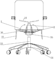
- FIG. 1 is a schematic diagram of the three-dimensional structure of the conversion between the sitting state and the standing state in Embodiment 1 of the present invention
- FIG. 2 is a schematic diagram of the three-dimensional structure of the main support body and the side support body in the sitting state of the present invention in the first embodiment
- FIG. 3 is a schematic diagram of the three-dimensional structure of the rotational connection between the rear end of the main support body and the side support body in Embodiment 1 of the present invention
- Figure 4 is a top view of the standing chair in a sitting state in the first embodiment of the present invention.
- FIG. 5 is a schematic diagram 1 of the three-dimensional structure of the main support body and the side support body in the sitting state of the present invention in the second embodiment;
- FIG. 6 is a schematic diagram 1 of the three-dimensional structure of the main support body and the side support body in the stance state of the present invention in the second embodiment;
- FIG. 7 is a second schematic diagram of the three-dimensional structure of the main support body and the side support body in the stance state of the present invention in the second embodiment;
- FIG 8 is the second three-dimensional structural schematic diagram of the main support body and the side support body in the sitting state of the present invention in the second embodiment;
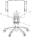
- FIG. 9 is a schematic diagram of a three-dimensional structure of a standing chair in a sitting state in Embodiment 3 of the present invention.
- Figure 10 is a top view of the standing chair in a sitting state in the third embodiment of the present invention.
- Figure 11 is a front view of the standing chair in a sitting state in the third embodiment of the present invention.
- FIG. 12 is a schematic diagram of the three-dimensional structure of the standing chair in the standing state in Embodiment 3 of the present invention.
- Figure 13 is a cross-sectional view in the direction C in Figure 18;
- FIG. 14 is a schematic diagram of the three-dimensional structure of the conversion between the sitting state and the standing state in Embodiment 3 of the present invention.
- 15 is a schematic diagram of the three-dimensional structure of the position-limiting member and the locking assembly in the sitting state in the fourth embodiment of the present invention.
- FIG. 16 is a schematic diagram of the three-dimensional structure of the restraint member and the locking assembly in the stance state of the present invention in Embodiment 4;
- Figure 17 is a rear view of the main and side support bodies and the lock pin cooperated with the limit disk in the sitting state in the fourth embodiment of the present invention.
- Figure 18 is a front view of the main and side support bodies and the lock pin and the limit plate in the sitting state in the fourth embodiment of the present invention.
- Figure 19 is a rear view of the main and side support bodies and the lock pin and the limit plate in the standing state in the fourth embodiment of the present invention.
- Fig. 20 is a front view of the main and side support bodies and the locking pin and the stop disc in the standing state in the fourth embodiment of the present invention.
- Figure 21 is a bottom view of the locking assembly in Embodiment 4 of the present invention.
- Figure 22 is a side view of the locking assembly in Embodiment 4 of the present invention.
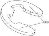
- FIG. 23 is a schematic diagram of a three-dimensional structure of an elastic card in Embodiment 4 of the present invention.
- FIG. 25 is a schematic diagram of the conversion of sitting and standing postures in Embodiment 4 of the present invention.
- 26 is a schematic diagram of the three-dimensional structure of the main and side supports in a sitting state in Embodiment 4 of the present invention.
- FIG. 27 is a schematic diagram of the three-dimensional structure of the main and side supports in the standing state in Embodiment 4 of the present invention.
- Fig. 28 is a partial enlarged view of part D in Fig. 21;
- Figure 29 is a partial enlarged view of part E in Figure 28;
- Figure 30 is a rear view of the main and side supports and the gear set in a sitting state of the present invention in Embodiment 5;
- Figure 31 is a schematic diagram of the three-dimensional structure of the transmission member and the locking pin in embodiment 5 of the present invention.
- Figure 32 is a rear view of the coupling of the transmission member and the locking pin in Embodiment 5 of the present invention.
- Figure 33 is a rear view of the transmission assembly in Embodiment 5 of the present invention.
- Figure 34 is a three-dimensional schematic diagram of the present invention with a first-stage gear and a transmission element on the long shaft in Embodiment 5;
- FIG. 36 is a schematic diagram of the three-dimensional structure of the support seat in the flat posture in Embodiment 6 of the present invention.
- FIG. 37 is a schematic diagram of the three-dimensional structure of the support base in an upright posture in Embodiment 6 of the present invention.
- the reference signs are: main support body 1; side support body 2; inner part 3; outer part 4; rotating shaft seat 5; rotating shaft 7; mounting plate 8; auxiliary support body 9; 11; lifting air rod 33; five-star foot 34; seat chassis 35; connecting rod 36; outer contour line 37; arched body 40; sponge extension 41; main support sponge 42; side support sponge 43; limiter 53 ; Locking component 54; Limiting plate 57; Lock pin 58; Sitting position locking groove 59; Standing position locking groove 510; Seat block 511; Base 512; Rotating shaft seat plate 513; Base plate seat 514; Connecting plate 515; Mounting seat 517; Piece 518; connecting part 519; vertical part 520; guide hole 521; control cable assembly 522; U-shaped groove 523; ring groove 524; elastic card 525; gasket 526; lock pin reset spring 527; elastic clamping arm 528; Gear set 74; mounting plate 75; primary gear 76; driven gear 77; rotating shaft hole 78; rotating shaft 79; long shaft 710
- the term "at least one” refers to one or more than one unless specifically defined otherwise.
- the terms “first”, “second”, “third”, etc. are only used for descriptive purposes, and cannot be understood as indicating or implying relative importance.
- the present invention provides a sitting and standing chair, comprising: a main support 1 and side supports 2 symmetrically arranged on both sides of the main support 1, and the side supports 2 can be opposite to the main support 1. Relative rotation occurs.
- the main support 1 is a seat plate, and a seat support assembly is provided under the main support 1.
- the seat support assembly includes a lifting air rod 33 and a five-star foot 34 and the seat chassis 35, the lifting air rod 33 is connected between the five-star foot 34 and the seat chassis 35, the main support body 1 is connected to the upper end of the seat chassis 35, and the main support body 1 can be raised and lowered by the lifting air rod 33.
- the side support 2 is a plate-shaped body. Along the width direction, the side support 2 has an inner part 3 close to the main support 1 and an outer part 4 away from the main support 1.
- the outer part 4 is the outer side of the side support 2.
- Partial margin refers to the outer partial marginal area of the side support 2 in a broad sense, and generally refers to the part that can support the human body to sit in the standing posture.
- the sitting and standing chair has a sitting state and a standing state; in the sitting state: the main support body 1 and the side support body 2 are in a flat posture, forming a seat surface for the user to sit flat, the seat surface can also be flat It can be an ergonomic curved surface; when transitioning from a sitting state to a standing state, turn the side supports 2 on both sides up to an upright position, which does not necessarily limit the side supports 2 to remain strictly perpendicular to the horizontal plane , More refers to the fact that after the side support 2 is turned up, the outer part 4 of the side support 2 can be at a higher height. During the upturning process, the main support 1 can remain fixed.
- the side support 2 In the upright posture, it can meet the height use requirements of most people in the standing posture; and when the side supports are in the upright posture, it cannot meet the sitting requirements of the human body in the standing posture, such as the user is too high Or if it is too short, the height of the main support 1 can be controlled by lifting the air rod 33, so as to meet the needs of the user.
- the inner part 3 of the side support body 2 can be connected to the left and right sides of the main support body 1 by hinge rotation, but at this time, in order to satisfy that the side support body 2 has a reasonable height after being turned up, and the two side support bodies 2 can be brought together
- the width of the main support 1 is usually reduced, which may make the contact surface between the main support 1 and the seat chassis 35 smaller and difficult to configure; in order to solve this problem, the side support The rotation connection of 2 is set at the inner side of the front and rear ends of the main support 1, so that the main support 1 and the seat chassis 35 under the main support 1 can maintain a sufficient contact area, and the side support The body 2 has a reasonable height after being turned upwards, and at the same time, the two side support bodies 2 can be as close as possible to facilitate the user to ride.
- the above-mentioned rotation connection is realized as follows: the side support body 2 is welded with a connecting rod 36 at the front and rear. 7 Rotate the connection.
- the above paragraphs describe the core idea of the present invention.
- the purpose of sitting-to-stand conversion is achieved through the upward turning of the side support 2; in actual use, in order to improve the comfort of use and the consideration of the sitting posture of the human body in the standing state, Optimize the design of the side support body 2.
- the outer part 4 extends downwards out of the standing support part 10, which is in the shape of a hanging ear and has a curved surface.
- the side support body 2 and the standing support part 10 are integrally formed; when the side support body 2 is turned up and fixed, the two standing support parts 10 are close together, and the standing support part 10 hangs down at the same time.
- the state is converted to a substantially horizontal state that is good for supporting the human body.
- the two standing support parts 10 form a saddle with a narrower width than the seat surface in the sitting state for the user to sit on.
- the side support body 2 needs to be limited in the sitting and standing states. There can be many such limiting methods.
- the following examples are as follows:
- the front and rear ends of the main support body 1 are provided with a rotating shaft seat 5, the side support body 2 and the rotating shaft seat 5 are connected by a connecting rod 36, and the same rotating shaft is penetrated on the rotating shaft seat 5 and the connecting rod 36 7.
- One end of the connecting rod 36 is provided with a mounting plate 8, which is connected and fixed to the lower surface of the side support 2 close to the inner part 3; the side support 2 drives the mounting plate 8 to rotate synchronously, so that the connecting rod 36 rotates around the shaft 7 .
- An auxiliary support 9 extends from the front of the side support 2 toward the middle of the main support 1.
- the auxiliary support 9 is used to increase the depth of the seat. In a sitting state, the side support 2 and the auxiliary support are viewed from above.
- the bodies 9 together form an L-shaped plate, and the outer contour line 37 of the formed L-shaped plate is curved, which makes the side support body 2 in an upright posture, making it easier for people to ride up;
- An auxiliary support 9 extends from the rear of the support 2.
- the auxiliary support 9 can be co-extended from the front and rear of the side support 2, so that the side support 2 and the auxiliary support 9 together form a U-shaped plate; whether it is a U-shaped plate or an L-shaped plate , It depends on the overall arrangement of the seat.
- the rotation of the side support 2 is controlled by the stop mechanism 11 to lock the side support 2 in the flat or upright position; the specific structure of the stop mechanism 11 is described in detail in the fourth embodiment.
- the main support body 1 and the side support body 2 are in a flat posture, forming a seat surface for the user to sit flat, the standing support portion 10 hangs on the left and right sides of the seat surface, and the side support body 2 is
- the limit mechanism 11 is locked and cannot be rotated; standing position: the limit mechanism 11 unlocks the side support body 2, and the side support body 2 rotates relative to the main support body 1 and turns the side support body 2 up to an upright position, while the side support body
- the outer part 4 of 2 is raised, the two standing support parts 10 are close to and form a saddle with the auxiliary support 9 to cater for the user to sit or lean on, and the side support 2 is locked by the stop mechanism 11 here;
- the lifting air rod 33 is controlled to raise or lower the main support body 1 and the side support body 2 in an upright posture to achieve a proper standing and sitting height.
- Embodiment 2 The difference between this embodiment and embodiment 1 is that in the standing state, considering the user’s sitting posture and meeting the user’s riding needs, a new design is made for the standing support part 10 .
- the outer part 4 of the side support body 2 extends downward and toward the inner part 3 of the side support body 2 to extend out of the standing posture support part 10, the standing posture support part 10 and the side support body 2
- the included angle is 10°-30°, so that in the sitting state, the standing support portion 10 does not appear to have a strong downward abrupt feeling.
- the two side supports 2 are in an upright position and are close to each other, the two The upper ends of the two side supports 2 are close to or close to each other, and the two standing support portions 10 and the upper ends of the two side supports 2 together form an arch body 40 that is convenient for the user to ride.
- the arch body 40 is in the shape of a saddle. It is convenient for users to ride and sit up, and at the same time, it has an ergonomic effect.
- Embodiment 3 The difference between this embodiment and Embodiments 1 and 2 is that in the standing state, considering the user’s sitting posture and meeting the user’s riding needs, the standing support part 10 has been updated. design.
- the above-mentioned stance supporting portion 10 and the side support body 2 are made of materials with strong plasticity.
- plasticity refers to the ability of the material to be bent and able to maintain this deformation, for example, but It is not limited to plastic; when the side support 2 is made of materials with poor plasticity, such as wood board, in order to ensure the comfort of use in the sitting state, the main support sponge 42 is laid on the upper surface of the main support, and the upper surface of the side support 2 is laid The side support sponge 43, while the sponge straddles the outer part 4 of the side support 2 and extends toward the inner part 3 of the side support 2, forming a sponge extension 41.
- the width of the sponge extension 41 can be determined according to actual conditions.
- the purpose is to make the user’s inner thigh contact with the sponge extension 41 after the user rides up in the standing posture, thereby improving the comfort of sitting; when the two side supports 2 are in an upright posture, the two side supports 2 The upper ends are close to or close to each other, and the two sponge extension bodies 41 and the upper ends of the side supports 2 together form a flexible support for the user to sit on.
- Embodiment 4 This embodiment describes in detail the limiting mechanism in Embodiment 1. It should be noted that the appearance of the seat in this embodiment is different from that in Embodiment 1, but the technical features are the same, such as the main support body 1 and the side supports The appearance of the body 2 has been changed; and the limit disk 57 can function as the connecting rod 36 in the first embodiment, so the connecting rod 36 can be omitted in this embodiment.
- the limiting mechanism of this embodiment includes a main support 1, a side support 2, a limiting member 53 and a locking assembly 54.
- the sitting and standing chair realizes the conversion of sitting and standing posture as follows: the main support body 1 is configured as the main body support of the seat surface of the sitting and standing chair; The supporting body 1 is rotatably connected; in the width direction, the side supporting body 2 has an inner part close to the main supporting body 1 and an outer part away from the main supporting body 1.
- the sitting and standing chair has a sitting state and a standing state; in the sitting state: the main support body 1 and the side support body 2 are in a flat posture, that is, the side support body 2 is flat. Spread on both sides of the main support body 1 to form a seat surface for the user to sit flat; standing position: the side support body 2 rotates relative to the main support body 1 and the side support body 2 is turned up to an upright position, and two The outer part of the side support 2 is raised and approached to a set distance to cater for the user to sit or lean on.
- the limiting member 53 as shown in Figures 15-20 is a disk-shaped body, called a limiting disk 57, the limiting disk 57 is provided with two locking grooves, and the limiting disk 57 is arranged on the side support 2;
- the locking assembly 54 is installed on the main support 1, and the locking assembly 54 includes a lock pin 58 that is selectively movable; when the side support 2 is turned over to a preset position relative to the main support 1, the lock pin 58 is locked with the corresponding lock pin 58.
- the groove lock cooperates to limit and lock the limit disk 57.
- An auxiliary support 9 extends from the front or rear of the side support 2 toward the middle of the main support 1.
- the auxiliary support 9 and the side support The body 2 surrounds the main support body 1; the auxiliary support body 9 is a part of the side support body 2, and the limit disc 57 is installed on the side support body 2; the lock pin 58 moves in the seat depth direction, and The limit disc 57 is arranged to face the moving direction of the lock pin 58.
- limit disks 57 There are a total of four limit disks 57, two at the front and rear.
- the limit disks 57 are respectively connected and fixed on the auxiliary support body 9 extended from the two side supports 2 and are rotatably connected with the main support body 1 through a rotating shaft;
- the position disk 57 is provided with a lock pin 58 correspondingly, and the lock pin 58 can be inserted into or withdrawn from the locking groove to lock or unlock the limit disk 57;
- the two locking grooves are the sitting position locking groove 59 and the standing position locking groove 510.
- the side supports 2 are laid flat on both sides of the main support 1, and the sitting locking groove 59 on the limit plate 57 is aligned with the lock pin 58.
- the lock pin 58 moves in the seat depth direction and is inserted into the sitting position lock In the groove 59, the sitting chair can be locked in the sitting state; in the standing state, the side support 2 is turned up to the upright position, and the stance locking groove 510 on the limit plate 57 is aligned with the locking pin 58, and the lock is now locked
- the pin 58 moves along the seat depth direction and inserts it into the standing position locking groove 510 to lock the sitting and standing chair in the standing position; when the sitting and standing chair needs to switch between sitting and standing positions, the locking pin 58 moves in the seat depth direction and moves from Withdraw from the locking groove, so that the side support 2 can rotate relative to the main support 1 to switch the desired sitting and standing chair state.
- the front and rear ends of the main support 1 extend downwards from a seat block 511.
- the seat block 511 is provided with a base 512.
- the base 512 includes a shaft seat plate 513 attached to the front or rear face of the seat block 511 and attached to the bottom surface of the seat block 511.
- the closed bottom plate seat 514; the limit disk 57 and the rotating shaft seat plate 513 are rotatably connected by the rotating shaft;
- the limit disk 57 is a semi-circular disk, and a connecting plate provided with a threaded hole extends in the direction of the limit disk 57 away from the arc 515, the connecting plate 515 and the limiting disk 57 are bent, the limiting disk 57 and the connecting plate 515 are integrally formed, and the limiting disk 57 is connected and fixed to the bottom surface of the auxiliary support body 9 through the connecting plate 515.
- the limit disc 57 is arranged on the bottom surface of the auxiliary support body 9, and the rotation point of the limit disc 57 and the main support body 1 is located below the main support body 1, that is, on the shaft seat plate 513 of the seat block 511. 57 is hidden under the seat surface, so that in the sitting state, the side support body 2 can be kept on the same level as the main support body 1, and the limit disk 57 is not obtrusive.
- the lock pin 58 performs the limit lock on the limit disk 57, and the lock pin 58 needs to move along the seat depth direction, specifically:
- the locking assembly 54 includes a mounting seat 517 and a paddle 518.
- the mounting seat 517 is disposed on the bottom plate seat 514, and the mounting seat 517 includes a connecting portion connected to the bottom plate seat 514. 519 and two vertical parts 520 arranged in parallel with the limit disk 57, and the vertical part 520 is integrally formed with the connecting part 519, the vertical part 520 is provided with a guide hole 521, and the lock pin 58 is arranged in the guide hole 521 Middle;
- the paddle 518 is vertically arranged and rotatably connected to the connecting portion 519, one end of the paddle 518 is connected to the lock pin 58, and the other end is connected with a control assembly, the control assembly controls the paddle 518 to rotate relative to the mounting seat 517, while dialing
- the piece 518 drives the lock pin 58 to move;
- the control component is a control cable component 522.
- the paddle 518 is connected to the lock pin 58 between the vertical portions 520.
- a U-shaped groove 523 is opened at one end of the paddle 518 connected to the lock pin 58.
- the U-shaped groove 523 connects the lock pin 58 is half-enclosed, the lock pin 58 in front of the U-shaped groove 523 is cut radially inward at a ring groove 524, and an elastic card 525 is provided on the ring groove 524; the paddle 518 drives the lock pin 58 to move by pushing the elastic card 525
- a gasket 526 is provided between the elastic card 525 and the paddle 518, and the gasket 526 is sleeved on the lock pin 58; a locking pin reset spring 527 is also sleeved on the lock pin 58 in front of the elastic card 525 to reset the lock pin.
- the spring 527 abuts on the vertical portion 520 of the mounting seat 517 and acts on the elastic card 525.
- the elastic card 525 is a ring-shaped body with an opening on the circumference.
- the ring-shaped body has two symmetrically arranged elastic clamping arms 528. It protrudes from the outer peripheral surface of the lock pin 58.
- the paddle 518 pushes the elastic card 525 to move the lock pin 58 in the direction of the guide hole 521, that is, in the seat depth direction, and the lock pin 58 is inserted to lock In the groove, the elastic card 525 compresses the lock pin return spring 527 at the same time; when the control cable assembly 522 is released, the lock pin return spring 527 rebounds to push the elastic card 525 so that the lock pin 58 exits the locking groove and returns to the initial position, while the paddle 518 Also rotate back to the initial position.
- a linkage mechanism is required. Including transmission components; when the sitting chair switches between the sitting state and the standing state, the transmission components act on the side supports 2 and cause the two side supports 2 to rotate synchronously; as shown in Figure 30-34, stand opposite
- the linkage mechanism of the chair is introduced as follows:
- the side support body 2 has a C-shape as a whole and surrounds the main support body 1; the transmission assembly is arranged between the two side supports 2 and the transmission assembly is located at the rear of the main support body 1. It is configured to transmit the rotating torque of the side support body 2 to the other side support body 2 when the one side support body 2 rotates and make the two side supports 2 rotate synchronously; there are many ways to realize the transmission assembly.
- the embodiment specifically introduces the transmission assembly of the gear transmission structure.
- the transmission assembly adopts a gear transmission structure, that is, the transmission assembly includes a gear set 74.
- the gear set 74 is arranged on the main support 1 through a mounting plate 75.
- the gear set 74 includes a side support
- the first-stage gear 76 of the body 2 rotates synchronously and the driven gear 77 that is meshed and arranged between the two first-stage gears 76; there are two driven gears 77 in total and mesh with each other; the mounting plate 75 and the main support 1
- the connection is fixed, the mounting plate 75 is provided with a rotating shaft hole 78, and the first-stage gear 76 and the driven gear 77 are both arranged on the mounting plate 75 through the rotating shaft 79 and are rotatably connected with the main support 1;
- the plate 75 separates the gear from the main support 1.
- the side support body 2 and the main support body 1 are rotatably connected by a long shaft 710.
- the long shaft 710 penetrates the main support body 1 back and forth and is inserted into the side support body 2.
- the primary gear 76 and the side support body 2 are both penetrated in The long axis 710.
- the transmission assembly further includes a transmission member 711, which is respectively fixedly connected to the primary gear 76 and the side support 2; specifically:
- the transmission member 711 is roughly a strip-shaped body, and the transmission member 711 penetrates the long shaft 710; the transmission member 711 includes a fixed portion 712 connected and fixed with the side support 2 and a limiting tip 713; In the width direction, the fixing portion 712 is located outside the long shaft 710, the fixing portion 712 is a rectangular plate-shaped body, and the lower end of the fixing portion 712 is bent to form an L-shaped plate-shaped body.
- the fixing portion 712 of the spool at the same time plays the role of connecting with the supporting side support 2; in the width direction of the seat, the limiting tip 713 is located on the inner side of the long axis 710, and the limiting tip 713 is a hook-shaped plate-shaped body , Its tip faces the inner side of the long shaft 710; the linkage mechanism also includes a locking pin 714 that is relatively fixed to the main support 1 and cooperates with the limiting tip 713, the locking pin 714 is arranged above the limiting tip 713; The pin 714 is configured to limit the limit tip 713 when it rotates to a preset position; that is, when the side support 2 is in a flat posture, the limit tip 713 abuts against the locking pin 714 above it, thereby acting Until the side support body 2 is prevented from turning downward.
- the first gear 76 has a transmission lug 715 extending outward in the radial direction.
- the transmission lug 715 is located between the mounting plate 75 and the fixing portion 712.
- the transmission member 711 and the transmission lug 715 are connected by a pin shaft. .
- the side support body 2 on one side rotates around the long shaft 710, it drives the transmission member 711 fixedly connected to it to rotate in the same direction.
- the fixed member drives the primary gear 76 to rotate in the same direction, because the two driven gears 77 mesh with each other.
- the supporting body 2 rotates in the reverse direction, so that the side supporting bodies 2 on both sides are turned up or down synchronously.
- the main support body 1 is always in a flat position, and a hollow support seat 90 is provided below the main support body 1.
- the support seat 90 is configured to connect to the seat support assembly, and the support seat The middle part of 90 sinks, the front and rear ends of the support base 90 are upturned, the main support body 1 is supported by the front and rear ends of the support base 90, and the side support body 1 is rotatably connected with the main support body 1; of course, the side support body 1 is also It can optionally be connected to the support base 90 in rotation.
- the main support 1 itself is a base, that is, a support seat.
- the main support 1 can be arranged under the side supports 2, and the main support 1 is in a hollow shape.
- the middle part of the main support body 1 sinks, the front and rear ends are upturned, and the side support body 2 is rotatably connected to the front and rear ends of the main support body 1, which is conducive to the simple and smooth design of the seat; the side support body 2 is arranged symmetrically, one of the two A straight slit 81 is formed between it, and an outer cover can be provided to cover the slit 81.
- the appearance of the seat is no different from that of a normal seat; uncover the outer cover and turn the side support 2 to an upright position to make the sitting stand
- the chair is switched to the standing state for the user to ride or lean on; the sitting and standing chair thus arranged has a simple structure and a simple appearance, which is more aesthetically pleasing.
Abstract
Chaise assis-debout, comprenant un corps de support principal (1) et des corps de support latéraux (2) agencés symétriquement sur les côtés gauche et droit du corps de support principal (1). Les corps de support latéraux (2) sont configurés pour tourner autour du corps de support principal (1). Dans la direction de la largeur, chaque corps de support latéral (2) présente une partie latérale interne (3) proche du corps de support principal (1) et une partie latérale externe (4) distante du corps de support principal (1). La chaise assis-debout présente un état de posture assise et un état de posture debout. Dans l'état de posture assise, le corps de support principal (1) et les corps de support latéraux (2) sont dans une position plate pour former une surface de siège permettant à un utilisateur de s'asseoir ; dans l'état de posture debout, les corps de support latéraux (2) sont entraînés en rotation par rapport au corps de support principal (1) et sont tournés vers le haut jusqu'à une position verticale, et les parties latérales externes (4) des corps de support latéraux (2) sont élevées pour permettre à l'utilisateur de s'asseoir ou de s'appuyer. Par comparaison avec l'état de la technique, la chaise assis-debout peut commuter entre la posture assise et la posture debout en posant les corps de support latéraux (2) à plat ou en tournant ces derniers vers le haut, présente une structure simple et est facile à actionner ; de plus, la hauteur de base est augmentée lorsque les corps de support latéraux (2) sont tournés vers le haut, ce qui permet à l'utilisateur de s'asseoir ou de s'appuyer dans l'état de posture debout.
Applications Claiming Priority (2)
| Application Number | Priority Date | Filing Date | Title |
|---|---|---|---|
| CN202010155043.2 | 2020-03-09 | ||
| CN202010155043 | 2020-03-09 |
Publications (1)
| Publication Number | Publication Date |
|---|---|
| WO2021179473A1 true WO2021179473A1 (fr) | 2021-09-16 |
Family
ID=72757024
Family Applications (1)
| Application Number | Title | Priority Date | Filing Date |
|---|---|---|---|
| PCT/CN2020/097555 WO2021179473A1 (fr) | 2020-03-09 | 2020-06-22 | Chaise assis-debout |
Country Status (2)
| Country | Link |
|---|---|
| CN (4) | CN212878506U (fr) |
| WO (1) | WO2021179473A1 (fr) |
Families Citing this family (1)
| Publication number | Priority date | Publication date | Assignee | Title |
|---|---|---|---|---|
| WO2021179473A1 (fr) * | 2020-03-09 | 2021-09-16 | 永艺家具股份有限公司 | Chaise assis-debout |
Citations (7)
| Publication number | Priority date | Publication date | Assignee | Title |
|---|---|---|---|---|
| CN202981015U (zh) * | 2012-12-10 | 2013-06-12 | 张建卿 | 多功能健身弹靠椅 |
| CN103829629A (zh) * | 2014-03-21 | 2014-06-04 | 上海电机学院 | 一种可坐可站的椅子 |
| US9131775B1 (en) * | 2012-12-05 | 2015-09-15 | Joel H. Eisenberg | Adjustable seating |
| CN106690963A (zh) * | 2016-12-17 | 2017-05-24 | 蒲若飞 | 可变马鞍椅椅面 |
| CN110664151A (zh) * | 2019-10-13 | 2020-01-10 | 永艺家具股份有限公司 | 一种坐站椅的座面形态变化控制装置 |
| CN110680107A (zh) * | 2019-10-13 | 2020-01-14 | 永艺家具股份有限公司 | 一种高安全性坐站工作椅 |
| CN111772402A (zh) * | 2020-03-09 | 2020-10-16 | 永艺家具股份有限公司 | 一种坐站椅 |
Family Cites Families (13)
| Publication number | Priority date | Publication date | Assignee | Title |
|---|---|---|---|---|
| JP3586300B2 (ja) * | 1994-11-12 | 2004-11-10 | 天龍工業株式会社 | 立姿勢用シート |
| ES2308935B1 (es) * | 2007-05-23 | 2009-10-26 | Juan Luis Bellvis Castillo | Dispositivo ergonomico de apoyo/asiento. |
| US8317267B2 (en) * | 2009-07-20 | 2012-11-27 | Jay Stuart Wallace | Ergonomic saddle chair |
| CA2954656A1 (fr) * | 2014-07-14 | 2016-01-21 | Exokinetics, Inc. | Deambulateur avec assise reglable en hauteur |
| CN206621104U (zh) * | 2016-12-17 | 2017-11-10 | 蒲若飞 | 可旋转双座面马鞍椅 |
| JP6248264B1 (ja) * | 2017-07-26 | 2017-12-20 | 豊充 品谷 | 立ち仕事兼用椅子 |
| JP6920156B2 (ja) * | 2017-09-28 | 2021-08-18 | 株式会社オカムラ | 椅子 |
| CN109953540B (zh) * | 2018-01-30 | 2024-01-23 | 永艺家具股份有限公司 | 一种坐站工作椅 |
| JP2019202625A (ja) * | 2018-05-23 | 2019-11-28 | トヨタ紡織株式会社 | 座席 |
| JP2019202626A (ja) * | 2018-05-23 | 2019-11-28 | トヨタ紡織株式会社 | 乗物用シート装置 |
| CN210077162U (zh) * | 2019-04-10 | 2020-02-18 | 赵云超 | 一种半站立式坐垫 |
| CN210114225U (zh) * | 2019-07-20 | 2020-02-28 | 蒲若飞 | 新型双翼可调节座椅 |
| CN110547624A (zh) * | 2019-09-05 | 2019-12-10 | 永艺家具股份有限公司 | 一种座椅单元及座椅 |
-
2020
- 2020-06-22 WO PCT/CN2020/097555 patent/WO2021179473A1/fr active Application Filing
- 2020-06-22 CN CN202021173902.2U patent/CN212878506U/zh active Active
- 2020-06-22 CN CN202010576526.XA patent/CN111772402A/zh active Pending
- 2020-09-16 CN CN202022023296.2U patent/CN213820632U/zh active Active
- 2020-09-16 CN CN202010971682.6A patent/CN112220261B/zh active Active
Patent Citations (7)
| Publication number | Priority date | Publication date | Assignee | Title |
|---|---|---|---|---|
| US9131775B1 (en) * | 2012-12-05 | 2015-09-15 | Joel H. Eisenberg | Adjustable seating |
| CN202981015U (zh) * | 2012-12-10 | 2013-06-12 | 张建卿 | 多功能健身弹靠椅 |
| CN103829629A (zh) * | 2014-03-21 | 2014-06-04 | 上海电机学院 | 一种可坐可站的椅子 |
| CN106690963A (zh) * | 2016-12-17 | 2017-05-24 | 蒲若飞 | 可变马鞍椅椅面 |
| CN110664151A (zh) * | 2019-10-13 | 2020-01-10 | 永艺家具股份有限公司 | 一种坐站椅的座面形态变化控制装置 |
| CN110680107A (zh) * | 2019-10-13 | 2020-01-14 | 永艺家具股份有限公司 | 一种高安全性坐站工作椅 |
| CN111772402A (zh) * | 2020-03-09 | 2020-10-16 | 永艺家具股份有限公司 | 一种坐站椅 |
Also Published As
| Publication number | Publication date |
|---|---|
| CN111772402A (zh) | 2020-10-16 |
| CN112220261A (zh) | 2021-01-15 |
| CN213820632U (zh) | 2021-07-30 |
| CN112220261B (zh) | 2023-07-25 |
| CN212878506U (zh) | 2021-04-06 |
Similar Documents
| Publication | Publication Date | Title |
|---|---|---|
| CA1287291C (fr) | Chaise therapeutique pouvant etre convertie pour l'adapter a diverses positions | |
| RU2437605C2 (ru) | Кресло с качающейся спинкой | |
| US4765684A (en) | Multi-purpose chair with retractable knee rest | |
| TWI235645B (en) | Ergonomic chair | |
| US20090091174A1 (en) | Ergonomic Armrest | |
| JPH0793898B2 (ja) | 椅子装置 | |
| US20080100119A1 (en) | Seating Furniture, In Particular Office Chairs | |
| WO2021179473A1 (fr) | Chaise assis-debout | |
| CN109363367A (zh) | 一种在课桌椅上实现午睡功能的方法及坐卧两用课桌椅 | |
| JP2024031988A (ja) | 自己適応連動制御の機能シングルチェア | |
| CN210520537U (zh) | 一种方便生产和使用的休闲椅 | |
| WO2023061066A1 (fr) | Siège | |
| CN213429200U (zh) | 一种坐站椅 | |
| KR101056745B1 (ko) | 의자용 좌판 틸팅장치 | |
| CN212878533U (zh) | 椅具的座面结构 | |
| CN113100598A (zh) | 一种多用椅子 | |
| CN212630358U (zh) | 多功能座椅 | |
| WO2018196480A1 (fr) | Fauteuil basculant multifonctionnel | |
| CN219594118U (zh) | 一种可快速同时操控座板靠背联动的午休椅 | |
| CN205963485U (zh) | 用于座椅单元的伸缩机架及座椅单元 | |
| CN218419065U (zh) | 一种自适应联动控制的功能单椅 | |
| CN220212410U (zh) | 一种坐站椅的支撑机构及座椅 | |
| JP3244406U (ja) | ドライブ・バイ・ワイヤートレイ及びチェア | |
| CN215456817U (zh) | 儿童座椅 | |
| CN219594114U (zh) | 一种午休式座椅 |
Legal Events
| Date | Code | Title | Description |
|---|---|---|---|
| 121 | Ep: the epo has been informed by wipo that ep was designated in this application |
Ref document number: 20923950 Country of ref document: EP Kind code of ref document: A1 |
|
| NENP | Non-entry into the national phase |
Ref country code: DE |
|
| 122 | Ep: pct application non-entry in european phase |
Ref document number: 20923950 Country of ref document: EP Kind code of ref document: A1 |