WO2021177403A1 - 回転電機 - Google Patents
回転電機 Download PDFInfo
- Publication number
- WO2021177403A1 WO2021177403A1 PCT/JP2021/008431 JP2021008431W WO2021177403A1 WO 2021177403 A1 WO2021177403 A1 WO 2021177403A1 JP 2021008431 W JP2021008431 W JP 2021008431W WO 2021177403 A1 WO2021177403 A1 WO 2021177403A1
- Authority
- WO
- WIPO (PCT)
- Prior art keywords
- flow path
- peripheral wall
- inner peripheral
- stator
- straight line
- Prior art date
- Legal status (The legal status is an assumption and is not a legal conclusion. Google has not performed a legal analysis and makes no representation as to the accuracy of the status listed.)
- Ceased
Links
Images





Classifications
-
- H—ELECTRICITY
- H02—GENERATION; CONVERSION OR DISTRIBUTION OF ELECTRIC POWER
- H02K—DYNAMO-ELECTRIC MACHINES
- H02K5/00—Casings; Enclosures; Supports
- H02K5/24—Casings; Enclosures; Supports specially adapted for suppression or reduction of noise or vibrations
-
- H—ELECTRICITY
- H02—GENERATION; CONVERSION OR DISTRIBUTION OF ELECTRIC POWER
- H02K—DYNAMO-ELECTRIC MACHINES
- H02K5/00—Casings; Enclosures; Supports
- H02K5/04—Casings or enclosures characterised by the shape, form or construction thereof
- H02K5/20—Casings or enclosures characterised by the shape, form or construction thereof with channels or ducts for flow of cooling medium
- H02K5/203—Casings or enclosures characterised by the shape, form or construction thereof with channels or ducts for flow of cooling medium specially adapted for liquids, e.g. cooling jackets
-
- H—ELECTRICITY
- H02—GENERATION; CONVERSION OR DISTRIBUTION OF ELECTRIC POWER
- H02K—DYNAMO-ELECTRIC MACHINES
- H02K2213/00—Specific aspects, not otherwise provided for and not covered by codes H02K2201/00 - H02K2211/00
- H02K2213/03—Machines characterised by numerical values, ranges, mathematical expressions or similar information
Definitions
- the present invention relates to a rotary electric machine.
- the rotary electric machine described in Patent Documents 1 and 2 includes a rotor, a stator arranged on the radial outer side of the rotor, and a housing in which the stator is housed.
- the stator has a tubular yoke portion and a teeth portion extending radially inward from the yoke portion.
- the rotary electric machine is configured to generate a rotating magnetic field by passing an electric current through a coil wound around a tooth portion, and to rotate the rotor by the magnetic force generated by the rotating magnetic field.
- the housing is formed with a refrigerant flow path through which the refrigerant for cooling the stator and the like flows.
- the housing has an inner peripheral wall in contact with the outer peripheral surface of the stator, an outer peripheral wall arranged radially outside the inner peripheral wall, and an inner peripheral wall and an outer peripheral wall in the radial direction as components forming the refrigerant flow path. It has a partition wall arranged between them.
- the partition wall portion is provided in a part of the housing in the circumferential direction, and connects the inner peripheral wall and the outer peripheral wall.
- An inlet of the refrigerant flow path is formed in the vicinity of the partition wall portion, and an outlet of the refrigerant flow path is formed on the opposite side of the inlet across the partition wall portion.
- the refrigerant that has flowed into the refrigerant flow path through the inlet flows around the refrigerant flow path substantially, and then flows out through the outlet.
- An object of the present invention is to suppress the vibration of the stator from being transmitted to the outer peripheral wall of the housing while suppressing the deterioration of the cooling function.
- a rotor capable of rotating with a predetermined axial direction as the rotation axis direction, a stator arranged outside the rotor in the radial direction of the rotor, and a refrigerant flow path through which the refrigerant flows are formed.
- a rotary electric machine having a flow path portion and a housing in which the rotor and the stator are housed.
- the flow path portion includes an inner peripheral wall in contact with the outer peripheral surface of the stator and the inner peripheral wall.
- An outer peripheral wall arranged on the outer side in the radial direction and provided so as to form the refrigerant flow path between the inner peripheral wall and the predetermined one in the circumferential direction orthogonal to both the axial direction and the radial direction. It has an inlet portion in which an inlet of the refrigerant flow path is formed at a position, and an outlet portion in which an outlet of the refrigerant flow path is formed at a position different from the predetermined position in the circumferential direction. Is a first flow path having a predetermined length from the inlet to the outlet in the circumferential direction, and a first flow path having a length from the inlet to the outlet in the circumferential direction shorter than that of the first flow path.
- the second flow path includes two flow paths, and the second flow path is provided with a partition wall portion between the inner peripheral wall and the outer peripheral wall in the radial direction, and the partition wall portion has a slit penetrating in the circumferential direction. Is formed, and the width of the slit is narrower than the width of the first flow path.
- a slit penetrating in the circumferential direction is formed in the partition wall portion, and the slit forms a gap between the outer portion and the inner portion in the radial direction of the partition wall portion.
- the width of the slit is narrower than the width of the first flow path, the flow path resistance of the second flow path can be increased, and the inflow of the refrigerant into the second flow path can be suppressed as much as possible. .. Therefore, it is possible to suppress the vibration of the stator from being transmitted to the outer peripheral wall of the housing while suppressing the deterioration of the cooling function.
- the slit extends from the position of one end of the outer peripheral surface of the stator to the position of the other end in the axial direction. It is characterized by being extended.
- the slit extends in the axial direction from at least the position of one end of the outer peripheral surface of the stator to the position of the other end. That is, in any cross section orthogonal to the axial direction, the portion of the inner peripheral wall adjacent to the stator and the outer peripheral wall are separated by a slit. Therefore, it is possible to effectively suppress the vibration of the stator from being transmitted from the inner peripheral wall to the outer peripheral wall via the partition wall portion.
- a supply flow path connected to the refrigerant flow path is formed at the inlet portion, and when viewed from the axial direction, the rotary electric machine is said.
- the straight line extending from the intersection to the first flow path side is defined as the first straight line, and from the intersection to the second flow path side.
- the angle formed by the center line and the first straight line is an obtuse angle
- the angle formed by the center line and the second straight line is an acute angle
- FIG. 1 is a view taken along the line II (b) of FIG.
- (A) and (b) are explanatory views showing the structure in the vicinity of the inlet of the refrigerant flow path.
- the vertical direction of the paper surface of FIG. 1 (the vertical direction of the paper surface of FIGS. 2A and 2B) is taken as the axial direction.
- the upper side of the paper surface of FIGS. 2A and 2B is one side in the axial direction.
- the lower side of the paper surface of FIGS. 2A and 2B is the other side in the axial direction.
- the radial direction of the rotor 11 (described later), which is a direction orthogonal to the axial direction, is hereinafter simply referred to as a radial direction.
- the direction orthogonal to both the axial direction and the radial direction is called the circumferential direction.
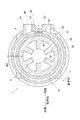
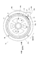
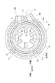
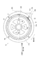
- FIG. 1 is a plan view of the rotary electric machine 1.
- FIG. 2A is a cross-sectional view taken along the line II (a) -II (a) of FIG.
- FIG. 2 (b) is a view taken along the line II (b) of FIG.
- FIG. 3 is a cross-sectional view orthogonal to the axial direction of the rotary electric machine 1.
- the rotary electric machine 1 has a motor 2 and a housing 3.
- the motor 2 is, for example, a known AC motor.
- the motor 2 has a rotor 11 that can rotate with the axial direction described above as the rotation axis direction, and a stator 12 that is arranged outside in the radial direction of the rotor 11.
- the motor 2 is configured such that the rotor 11 is rotated by a rotating magnetic field generated when an alternating current is flowing through a coil (not shown) wound around the stator 12.
- the rotor 11 is a substantially cylindrical member having, for example, a permanent magnet (not shown).
- the rotor 11 is arranged inside the stator 12 in the radial direction.
- a rotating shaft 13 is fitted in the rotor 11.
- the configuration of the rotor 11 is not limited to this.
- the rotor 11 may have a plurality of salient poles protruding in a direction orthogonal to the rotation axis direction (that is, the motor 2 may be, for example, a switched reluctance motor).
- the stator 12 is a substantially tubular member made of a magnetic member such as carbon steel.
- the stator 12 is arranged on the outer side of the rotor 11 in the radial direction.
- the stator 12 is fitted in the housing 3.
- the stator 12 has a substantially cylindrical yoke portion 21 formed over the entire circumference in the circumferential direction, and a plurality of teeth portions 22 extending inward in the radial direction from a part of the yoke portion 21 in the circumferential direction. ..
- the six tooth portions 22 are arranged at substantially equal intervals in the circumferential direction.
- a coil (not shown) is wound around each tooth portion 22.
- the coil is electrically connected to a power supply (not shown).
- the power supply unit supplies the motor 2 with electric power for passing an alternating current through the coil. More specifically, the power supply unit is an alternating current having the same phase as a pair of coils wound around a pair of teeth portions 22 located on opposite sides of the rotor 11 of the six teeth portions 22. Power is supplied so that current can flow.
- the power supply device supplies electric power so that three types of alternating currents having 120 degrees out of phase with each other flow through the three pairs of coils (general three-phase alternating current).
- the housing 3 is a case member that accommodates the motor 2 that opens on one side in the axial direction.
- the housing 3 is made of, for example, die-cast aluminum alloy formed by a general die-casting method.
- the material of the housing 3 does not necessarily have to be an aluminum alloy.
- the housing 3 may be formed of a metal such as iron, or may be formed of a member other than metal.
- the housing 3 does not necessarily have to be formed by a die casting method, and may be formed by another known casting method or the like.
- the housing 3 has a flow path portion 30 in which a refrigerant flow path 31 through which a refrigerant for cooling the motor 2 flows is formed.
- the flow path portion 30 includes an inner peripheral wall 32, an outer peripheral wall 33, a bottom portion 34, an inlet portion 35, an outlet portion 36, and a partition wall portion 37. And have.
- the inner peripheral wall 32 extends in the axial direction and is formed over the entire circumference in the circumferential direction.
- the inner peripheral surface 32a of the inner peripheral wall 32 is in contact with the outer peripheral surface 12a of the stator 12. In this way, the stator 12 is fitted to the inner peripheral wall 32 of the housing 3.
- the outer peripheral wall 33 extends in the axial direction like the inner peripheral wall 32, and is formed over the entire circumference in the circumferential direction.
- the outer peripheral wall 33 is arranged outside the inner peripheral wall 32 in the radial direction, and is arranged side by side with the inner peripheral wall 32 in the radial direction.
- the outer peripheral wall 33 is provided so as to leave a gap of a predetermined size between the outer peripheral wall 33 and the inner peripheral wall 32 in the radial direction.
- the size of the gap formed between the inner peripheral wall 32 and the outer peripheral wall 33 is, for example, substantially constant in the circumferential direction (see FIG. 3).
- the bottom portion 34 is provided at the other end of the housing 3 in the axial direction, and connects the inner peripheral wall 32 and the outer peripheral wall 33 in the radial direction.
- the inner peripheral wall 32, the outer peripheral wall 33, and the bottom portion 34 form a refrigerant flow path 31 having a substantially U-shaped cross section (see FIG. 2A) so as to extend in the circumferential direction.
- the refrigerant flow path 31 is formed between the inner peripheral wall 32 and the outer peripheral wall 33.
- the inlet portion 35 is a portion where the inlet 41 for supplying the refrigerant to the refrigerant flow path 31 is formed. As shown in FIG. 1, the inlet 41 opens to the inner peripheral surface 33a of the outer peripheral wall 33 at a predetermined position in the circumferential direction. Further, the outer peripheral wall 33 is provided with a supply pipe portion 42 protruding outward in the radial direction. A through hole (supply flow path 43) including an inlet 41 is formed from the tip of the supply pipe portion 42 to the inner peripheral surface 33a of the outer peripheral wall 33. The supply flow path 43 is connected to the refrigerant flow path 31 via the inlet 41. In the present embodiment, the supply flow path 43 extends in a direction substantially orthogonal to the axial direction, but is not limited to this.
- the outlet portion 36 is a portion where an outlet 44 for discharging the refrigerant from the refrigerant flow path 31 is formed.
- the outlet 44 like the inlet 41, opens to the inner peripheral surface 33a of the outer peripheral wall 33.
- the position of the outlet 44 in the circumferential direction is different from the position of the inlet 41 in the circumferential direction (predetermined position described above).
- the outer peripheral wall 33 is provided with a discharge pipe portion 45 projecting outward in the radial direction.
- a through hole (discharge flow path 46) including an outlet 44 is formed from the inner peripheral surface 33a of the outer peripheral wall 33 to the tip of the discharge pipe portion 45.
- the discharge flow path 46 is connected to the refrigerant flow path 31 via the outlet 44.
- the inlet portion 35 and the outlet portion 36 are arranged so as to be substantially line-symmetric with respect to the partition wall portion 37 when viewed from the axial direction (see FIG. 1). Further, the supply flow path 43 and the discharge flow path 46 are arranged substantially in parallel, but the present invention is not limited to this.
- the refrigerant flow path 31 includes, for example, a virtual straight line L1 extending in the radial direction and passing through the center of the inlet 41 and a virtual straight line L2 extending in the radial direction and passing through the center of the outlet 44. It can be roughly divided into two types. That is, the refrigerant flow path 31 has a first flow path 51 having a predetermined length in the circumferential direction from the inlet 41 to the outlet 44 and a first flow path having a length in the circumferential direction from the inlet 41 to the outlet 44. It is divided into a second flow path 52 shorter than 51.
- the first flow path 51 occupies substantially the entire circumference of the refrigerant flow path 31. In the present embodiment, the width of the first flow path 51 in the radial direction is substantially constant in the circumferential direction (see FIG. 3).
- the second flow path 52 is the remaining portion of the refrigerant flow path 31 excluding the first flow path 51.
- the partition wall portion 37 is for suppressing the refrigerant that has flowed into the refrigerant flow path 31 through the inlet 41 from flowing out from the outlet 44 through the short second flow path 52.
- the partition wall portion 37 is provided in a part (in the middle of the second flow path 52) in the circumferential direction, and is arranged between the inner peripheral wall 32 and the outer peripheral wall 33 in the radial direction.
- the partition wall portion 37 is integrally formed with the inner peripheral wall 32 and the outer peripheral wall 33, and extends in the axial direction (see FIG. 2A).
- the partition wall portion 37 may be provided as a member different from the inner peripheral wall 32 and the outer peripheral wall 33. More details of the partition wall portion 37 will be described later.
- a substantially disk-shaped lid member 38 is fixed to one end of the housing 3 in the axial direction by a fixture (not shown). As a result, the refrigerant flow path 31 is sealed except for the inlet 41 and the outlet 44.
- the teeth portion 22 vibrates and the vibration is transmitted to the entire stator 12.
- the outer peripheral wall 33 vibrates and noise may be generated.
- the second flow path 52 is from the inlet 41 to the outlet.
- the partition wall portion 37 of the housing 3 is configured as follows in order to suppress the vibration of the stator from being transmitted to the outer peripheral wall 33 of the housing 3 while suppressing the deterioration of the cooling function.
- Partition wall The configuration of the partition wall portion 37 will be described with reference to FIGS. 1 to 3.
- a slit 53 is formed in the partition wall portion 37.
- the slit 53 When viewed from the axial direction, the slit 53 extends, for example, in a straight line.
- the slit 53 communicates the spaces on both sides of the partition wall portion 61 in the circumferential direction.
- the slit 53 penetrates the partition wall portion 37 in the circumferential direction (see FIG. 1).
- the slit 53 forms a gap between the outer portion and the inner portion of the partition wall portion 37 in the radial direction. Due to such a gap, the vibration of the stator 12 accompanying the rotation of the rotor 11 is suppressed from being transmitted from the inner peripheral wall 32 to the outer peripheral wall 33 via the partition wall portion 37.
- the slit 53 extends in the axial direction (see FIG. 2). In the axial direction, the slit 53 extends to one side of the one-sided end surface 12b of the stator 12, and extends to the other side of the other end surface 12c of the stator 12. In other words, in the axial direction, the slit 53 extends unilaterally from one end of the outer peripheral surface 12a of the stator 12, and extends to the other side of the other end of the outer peripheral surface 12a. In other words, the slit 53 extends from the position of at least one end of the outer peripheral surface 12a of the stator 12 to the position of the other end in the axial direction. That is, in any cross section orthogonal to the axial direction (see, for example, FIG.
- the contact portion of the inner peripheral wall 32 with the stator 12 and the outer peripheral wall 33 are separated by the slit 53. Therefore, it is effectively suppressed that the vibration of the stator 12 is transmitted from the inner peripheral wall 32 to the outer peripheral wall 33 via the partition wall portion 37.
- the slit 53 forms a short-circuit path from the inlet 41 to the outlet 44 in the second flow path 52, the amount of refrigerant flowing into the second flow path 52 increases and the amount of refrigerant flowing through the first flow path 51 decreases. There is a concern that the cooling function will deteriorate. Therefore, as shown in FIG. 3, the width W1 in the radial direction of the slit 53 is narrower than the width W2 (the gap between the inner peripheral wall 32 and the outer peripheral wall 33 in the radial direction) in the radial direction of the first flow path 51. There is. Therefore, since the flow path resistance of the second flow path 52 becomes large, the inflow of the refrigerant into the second flow path 52 is suppressed.
- the slit 53 forms a gap between the outer portion and the inner portion of the partition wall portion 37 in the radial direction. As a result, it is possible to suppress the vibration of the stator 12 accompanying the rotation of the rotor 11 from being transmitted from the inner peripheral wall 32 to the outer peripheral wall 33. Further, since the width W1 of the slit 53 is narrower than the width W2 of the first flow path 51 (the gap between the inner peripheral wall 32 and the outer peripheral wall 33 in the radial direction), the flow path resistance of the second flow path 52 can be increased. Therefore, the inflow of the refrigerant into the second flow path 52 can be suppressed as much as possible. Therefore, it is possible to suppress the vibration of the stator 12 from being transmitted to the outer peripheral wall 33 of the housing 3 while suppressing the deterioration of the cooling function.
- the slit 53 extends from the position of at least one end of the outer peripheral surface 12a of the stator 12 to the position of the other end in the axial direction. That is, in any cross section orthogonal to the axial direction, the contact portion of the inner peripheral wall 32 with the stator 12 and the outer peripheral wall 33 are separated by the slit 53. Therefore, it is possible to effectively suppress the vibration of the stator 12 from being transmitted from the inner peripheral wall 32 to the outer peripheral wall 33 via the partition wall portion 37.
- the slit 53 is assumed to extend linearly when viewed from the axial direction, but the present invention is not limited to this.
- the partition wall portion 61 may be formed with a slit 62 having a substantially S-shape when viewed from the axial direction. Similar to the slit 53 described above, the slit 62 communicates the spaces on both sides of the partition wall portion 61 in the circumferential direction. In other words, such a slit 62 also penetrates the partition wall portion 61 in the circumferential direction.
- the slit 62 may be curved in this way as long as it is formed so as to penetrate the partition wall portion 61 in the circumferential direction and is narrower than the width of the first flow path 51.
- FIG. 5 is a plan view of the rotary electric machine 1b.
- 6 (a) and 6 (b) are explanatory views showing a configuration in the vicinity of the inlet 41b of the refrigerant flow path 31b.
- the inlet portion 35b in which the inlet 41b is formed and the outlet portion 36b in which the outlet 44b is formed do not have to be arranged line-symmetrically when viewed from the axial direction.
- the supply flow path 43b may be arranged so as to be relatively inclined toward the second flow path 52b side as compared with the above-described embodiment.
- the relationship between the supply flow path 43b formed in the supply pipe portion 42b and the outer edge 32b of the inner peripheral wall 32 is as follows. That is, the center line passing through the center of the supply flow path 43b in the flow path width direction is defined as the center line L3.
- the tangent line of the outer edge 32b passing through the intersection P of the center line L3 and the outer edge 32b of the inner peripheral wall 32 is defined as the tangent line L4.
- the straight line extending from the intersection P toward the first flow path 51b is referred to as the first straight line L5.
- a straight line extending from the intersection P toward the second flow path 52b is referred to as a second straight line L6.
- the angle ⁇ 1 formed by the center line L3 and the first straight line L5 is an obtuse angle
- the angle ⁇ 2 formed by the center line L3 and the second straight line L6 is an acute angle.
- the housing 3c (see FIG. 7) of the rotary electric machine 1c may be configured as follows in order to further suppress the deterioration of the cooling function. That is, as shown in FIG. 7, the supply pipe portion 42c may be provided so that the supply flow path 43c is not parallel to the discharge flow path 46c and is inclined toward the second flow path 52c. As a result, the angle formed by the center line L7 of the supply flow path 43c and the first straight line L8 corresponding to the first straight line L5 described above can be made an obtuse angle. Further, the angle formed by the center line L7 and the second straight line L9 corresponding to the second straight line L6 described above can be an acute angle. In this way, the refrigerant that has flowed into the refrigerant flow path 31c may be facilitated to flow toward the first flow path 51c, and the refrigerant may be suppressed from flowing toward the second flow path 52c.
- the number of tooth portions 22 of the stator 12 is 6, and a three-phase alternating current is passed through the coil, but the present invention is not limited to this.
- the number of teeth portions 22 does not have to be six, and a current other than three-phase alternating current (for example, single-layer alternating current) may be passed through the coil.
- the teeth portions 22 do not necessarily have to be arranged at equal intervals in the circumferential direction. The sizes of all the teeth portions 22 do not necessarily have to be the same.
- the slit 53 and the like extend from the position of at least one end of the outer peripheral surface 12a of the stator 12 to the position of the other end in the axial direction.
- the slit may be formed so as to fit inside the stator 12 in the axial direction.
- the width of the first flow path 51 is assumed to be constant in the circumferential direction, but the present invention is not limited to this.
- the width of the first flow path 51 does not have to be constant in the circumferential direction.
- at least the width of the narrowest portion of the slit 53 must be smaller than the width of the narrowest portion of the first flow path 51. Is preferable.
- the supply flow path 43 and the discharge flow path 46 are assumed to be substantially orthogonal to the axial direction, but the present invention is not limited to this.
- the supply flow path 43 and the discharge flow path 46 do not necessarily have to be orthogonal to the axial direction.
- the motor 2 is an AC motor, but the present invention is not limited to this.
- the present invention may be applied to a DC motor.
- the rotary electric machine 1 and the like have a motor 2 for rotating the rotating shaft 13, but the present invention is not limited to this.
- a generator may be provided in which the rotating shaft 13 is rotated by an external force to generate an electromotive force in the coil by electromagnetic induction.
- the motor 2 may be used as a generator. Even in such a case, the teeth portion 22 may vibrate due to the intermittent generation of a magnetic force between the rotor 11 and the teeth portion 22, so that the inner peripheral wall 32 and the outer peripheral wall 33 are disconnected by the slit 53. Is effective.
- the housing 3d of the rotary electric machine 1d is not provided with a partition wall. That is, a refrigerant flow path 31d having substantially the same width is provided over the entire circumference in the circumferential direction, and is divided into a first flow path 51d and a second flow path 52d.
- the configuration of the housing 3d is the same as that of the housing 3b. That is, the housing 3d has the above-mentioned inlet portion 35b, outlet portion 36b, inlet 41b, supply pipe portion 42b, supply flow path 43b, and outlet 44b.
- the angle formed by the center line L3 and the first straight line L5 is an obtuse angle
- the angle formed by the center line L3 and the second straight line L6 is an acute angle (see FIG. 9) so that the refrigerant flows into the first flow path 51d. It is possible to facilitate the flow to the side and prevent the refrigerant from flowing to the second flow path 52d side.
- a rotor that can rotate with a predetermined axial direction as the rotation axis direction, With a stator arranged outside the rotor in the radial direction of the rotor, A rotary electric machine having a flow path portion in which a refrigerant flow path through which a refrigerant flows is formed, and including a rotor and a housing in which the stator is housed.
- the flow path portion An inner peripheral wall in contact with the outer peripheral surface of the stator, An outer peripheral wall arranged on the outer side of the inner peripheral wall in the radial direction and provided so as to form the refrigerant flow path between the inner peripheral wall and the inner peripheral wall.
- An inlet portion in which an inlet of the refrigerant flow path is formed at a predetermined position in a circumferential direction orthogonal to both the axial direction and the radial direction. It has an outlet portion in which an outlet of the refrigerant flow path is formed at a position different from the predetermined position in the circumferential direction.
- the refrigerant flow path is A first flow path having a predetermined length from the inlet to the outlet in the circumferential direction, A second flow path having a length from the inlet to the outlet in the circumferential direction shorter than that of the first flow path is included.
- a supply flow path connected to the refrigerant flow path is formed at the inlet portion.
- rotary electric machine 3 housing 11 rotor 12 stator 12a outer peripheral surface 30 flow path part 31 refrigerant flow path 32 inner peripheral wall 32b outer edge 33 outer peripheral wall 35 inlet part 36 outlet part 37 partition wall part 41 inlet 43 supply flow path 44 outlet 51 first flow path 52 Second flow path 53 Slit L3 Center line L4 Tangent line L5 First straight line L6 Second straight line P Intersection W1 Width W2 Width ⁇ 1 Angle ⁇ 2 Angle
Landscapes
- Engineering & Computer Science (AREA)
- Power Engineering (AREA)
- Motor Or Generator Cooling System (AREA)
- Motor Or Generator Frames (AREA)
- Iron Core Of Rotating Electric Machines (AREA)
Abstract
回転電機1は、ロータ11と、ステータ12と、流路部30を有するハウジング3とを備える。流路部30は、ステータ12の外周面12aと接触した内周壁32と、内周壁32の径方向における外側に配置され、内周壁32との間に冷媒流路31が形成されるように設けられた外周壁33と、周方向の所定位置に入口41が形成された入口部35と、所定位置とは異なる位置に出口44が形成された出口部36とを有する。冷媒流路31は、第1流路51と、第1流路51よりも周方向における長さが短い第2流路52とを含む。第2流路52には、径方向において内周壁32と外周壁33との間に配置され、周方向に貫通したスリット53が形成された隔壁部37が設けられている。スリット53の幅W1は、第1流路51の幅W2よりも狭い。
Description
本発明は、回転電機に関する。
特許文献1、2に記載された回転電機は、ロータと、ロータの径方向外側に配置されたステータと、前記ステータが収容されたハウジングとを備える。ステータは、筒状のヨーク部と、ヨーク部から径方向内側に延びたティース部とを有する。回転電機は、ティース部に巻かれたコイルに電流を流すことにより回転磁界を生成し、回転磁界により発生する磁力によってロータを回転させるように構成されている。
ハウジングには、ステータ等を冷却するための冷媒が流れる冷媒流路が形成されている。ハウジングは、冷媒流路を形成する構成要素として、ステータの外周面に接触している内周壁と、内周壁の径方向外側に配置された外周壁と、径方向において内周壁と外周壁との間に配置された隔壁部とを有する。隔壁部は、ハウジングの周方向における一部に設けられ、内周壁と外周壁とを接続している。隔壁部の近傍には冷媒流路の入口が形成され、隔壁部を挟んで入口の反対側には冷媒流路の出口が形成されている。入口を通って冷媒流路に流入した冷媒は、冷媒流路をほぼ一周するように流れた後、出口を通って流出する。
上述した回転電機においては、ロータの回転時に、ロータとティース部との間に磁力が断続的に作用し、これによりステータが振動する。このような振動が、ステータから内周壁に伝わり、さらに、例えば隔壁部を介して内周壁から外周壁に伝わると、外周壁が振動することにより騒音が発生しうる。騒音の対策の一つとして、隔壁部を設けず、内周壁から外周壁に振動が伝わることを抑制することが考えられる。しかしながら、この場合、入口から出口にかけて短絡経路が形成され、短絡経路に冷媒が多く流れ込みやすくなるおそれがある。このため、本来の冷媒流路に流れる冷媒の量が大きく減少し、冷却機能が大きく損なわれるという問題が生じうる。
本発明の目的は、冷却機能の低下を抑制しつつ、ステータの振動がハウジングの外周壁まで伝わることを抑制することである。
第1の発明の回転電機は、所定の軸方向を回転軸方向として回転可能なロータと、前記ロータの径方向において前記ロータの外側に配置されたステータと、冷媒が流れる冷媒流路が形成された流路部を有し、前記ロータ及び前記ステータが収容されたハウジングと、を備えた回転電機であって、前記流路部は、前記ステータの外周面と接触した内周壁と、前記内周壁の前記径方向における外側に配置され、前記内周壁との間に前記冷媒流路が形成されるように設けられた外周壁と、前記軸方向及び前記径方向の両方と直交する周方向における所定位置に前記冷媒流路の入口が形成された入口部と、前記周方向において前記所定位置とは異なる位置に前記冷媒流路の出口が形成された出口部と、を有し、前記冷媒流路は、前記入口から前記出口までの前記周方向における長さが所定長さである第1流路と、前記入口から前記出口までの前記周方向における長さが前記第1流路よりも短い第2流路と、を含み、前記第2流路には、前記径方向において前記内周壁と前記外周壁との間に隔壁部が設けられ、前記隔壁部には、前記周方向に貫通したスリットが形成され、前記スリットの幅は、前記第1流路の幅よりも狭いことを特徴とするものである。
本発明では、周方向に貫通したスリットが隔壁部に形成されており、スリットによって隔壁部の径方向における外側部分と内側部分との間に隙間が形成されている。これにより、ロータの回転に伴うステータの振動が内周壁から外周壁に伝わることを抑制できる。但し、当該スリットによって入口から出口にかけて短絡経路が形成されるので、これによって第2流路に流れ込む冷媒が増えて第1流路を流れる冷媒が減り、冷却機能が低下する懸念がある。この点、本発明では、スリットの幅が第1流路の幅よりも狭いため、第2流路の流路抵抗を大きくすることができ、第2流路への冷媒の流れ込みを極力抑制できる。したがって、冷却機能の低下を抑制しつつ、ステータの振動がハウジングの外周壁に伝わることを抑制できる。
第2の発明の回転電機は、前記第1の発明において、前記スリットは、前記軸方向において、少なくとも、前記ステータの前記外周面の一方側の端の位置から他方側の端の位置に亘って延びていることを特徴とするものである。
本発明では、スリットが、軸方向において、少なくともステータの外周面の一方側の端の位置から他方側の端の位置に亘って延びている。つまり、軸方向と直交するいずれの断面においても、内周壁のステータとの隣接部分と、外周壁とがスリットによって分断されている。したがって、ステータの振動が隔壁部を介して内周壁から外周壁に伝わることを効果的に抑制できる。
第3の発明の回転電機は、前記第1又は第2の発明において、前記入口部には、前記冷媒流路と接続された供給流路が形成され、前記軸方向から見たときに、前記供給流路の中心線と前記内周壁の外縁との交点を通る前記外縁の接線のうち、前記交点から前記第1流路側へ延びる直線を第1直線とし、前記交点から前記第2流路側へ延びる直線を第2直線としたとき、前記中心線と前記第1直線とのなす角が鈍角であり、前記中心線と前記第2直線とのなす角が鋭角であることを特徴とするものである。
本発明では、中心線と第1直線とのなす角が鈍角であり、中心線と第2直線とのなす角が鋭角である。これにより、供給流路を通って冷媒流路に流れ込んだ冷媒は、内周壁の外縁に当たったときに、第1流路側へ流れやすくなり、且つ、第2流路側へ流れ込むことが抑制される。したがって、冷却機能の低下をいっそう効果的に抑制できる。
次に、本発明の実施の形態について説明する。なお、図1の紙面垂直方向(図2(a)、(b)の紙面上下方向)を軸方向とする。図2(a)、(b)の紙面上側を軸方向における一方側とする。図2(a)、(b)の紙面下側を軸方向における他方側とする。軸方向と直交する方向である、ロータ11(後述)の径方向を、以下、単に径方向と呼ぶ。軸方向及び径方向の両方と直交する方向を周方向と呼ぶ。
(回転電機)
まず、本実施形態に係る回転電機1の構成について、図1~図3を参照しつつ説明する。図1は、回転電機1の平面図である。図2(a)は、図1のII(a)-II(a)線断面図である。図2(b)は、図1のII(b)矢視図である。図3は、回転電機1の軸方向と直交する断面図である。
まず、本実施形態に係る回転電機1の構成について、図1~図3を参照しつつ説明する。図1は、回転電機1の平面図である。図2(a)は、図1のII(a)-II(a)線断面図である。図2(b)は、図1のII(b)矢視図である。図3は、回転電機1の軸方向と直交する断面図である。
図1に示すように、回転電機1は、モータ2と、ハウジング3とを有する。モータ2は、例えば公知の交流モータである。モータ2は、上述した軸方向を回転軸方向として回転可能なロータ11と、ロータ11の径方向における外側に配置されたステータ12とを有する。モータ2は、ステータ12に巻かれた不図示のコイルに交流電流が流れているときに生成される回転磁界によって、ロータ11が回転するように構成されている。
ロータ11は、例えば不図示の永久磁石を有する略円筒状の部材である。ロータ11は、ステータ12の径方向における内側に配置されている。ロータ11には回転軸13が嵌装されている。なお、ロータ11の構成はこれに限られない。例えば、ロータ11は、回転軸方向と直交する方向に突出した複数の突極を有していても良い(つまり、モータ2は、例えばスイッチトリラクタンスモータであっても良い)。ステータ12は、例えば炭素鋼等の磁性部材からなる概ね筒状の部材である。ステータ12は、ロータ11の径方向における外側に配置されている。ステータ12は、ハウジング3に嵌装されている。ステータ12は、周方向において全周に亘って形成された略円筒状のヨーク部21と、ヨーク部21の周方向における一部からそれぞれ径方向における内側へ延びた複数のティース部22とを有する。本実施形態では、6個のティース部22が周方向において略等間隔に配置されている。
各ティース部22の周囲には、不図示のコイルが巻かれている。コイルは、不図示の電源装置と電気的に接続されている。電源装置は、交流電流をコイルに流すための電力をモータ2に供給する。より具体的には、電源装置は、6個のティース部22のうちロータ11を挟んで互いに反対側に位置している1対のティース部22に巻かれた1対のコイルに同位相の交流電流が流れるように電力を供給する。本実施形態では、電源装置は、位相が互いに120度異なる3種類の交流電流が3対のコイルにそれぞれ流れるように電力を供給する(一般的な三相交流)。
このようなモータ2において、上述したような電力がコイルに供給されると、所定の周期で周方向に回転する回転磁界が生成され、回転磁界の磁極とロータ11との間に磁力が発生する。これにより、ロータ11は、回転磁界に追随するように回転軸13とともに回転する。
ハウジング3は、軸方向における一方側に開口した、モータ2を収容するケース部材である。ハウジング3は、例えば、一般的なダイキャスト法によって形成された、アルミ合金のダイキャストからなる。なお、ハウジング3の材質は必ずしもアルミ合金でなくても良い。例えば、ハウジング3は鉄等の金属により形成されていても良く、或いは金属以外の部材によって形成されていても良い。また、ハウジング3は、必ずしもダイキャスト法によって形成されたものでなくても良く、他の公知の鋳造法等によって形成されていても良い。ハウジング3は、モータ2を冷却するための冷媒が流れる冷媒流路31が形成された流路部30を有する。図1及び図2(a)、(b)に示すように、流路部30は、内周壁32と、外周壁33と、底部34と、入口部35と、出口部36と、隔壁部37とを有する。
内周壁32は、軸方向に延び、且つ、周方向において全周に亘って形成されている。内周壁32の内周面32aは、ステータ12の外周面12aに接触している。このようにして、ステータ12がハウジング3の内周壁32に嵌装されている。外周壁33は、内周壁32と同様に軸方向に延び、且つ、周方向において全周に亘って形成されている。外周壁33は、内周壁32の径方向における外側に配置され、径方向において内周壁32と並べて配置されている。外周壁33は、径方向において内周壁32との間に所定の大きさの隙間を空けるように設けられている。内周壁32と外周壁33との間に形成された上記隙間の大きさは、例えば、周方向において略一定である(図3参照)。底部34は、ハウジング3の軸方向における他方側の端部に設けられ、径方向において内周壁32と外周壁33とを接続している。内周壁32と外周壁33と底部34とによって、断面略U字形(図2(a)参照)の冷媒流路31が、周方向に延びるように形成されている。言い換えると、内周壁32と外周壁33との間に冷媒流路31が形成されている。
入口部35は、冷媒を冷媒流路31に供給するための入口41が形成された部分である。図1に示すように、入口41は、周方向における所定位置において、外周壁33の内周面33aに開口している。また、外周壁33には、径方向における外側へ突出した供給管部42が設けられている。供給管部42の先端から外周壁33の内周面33aに亘って、入口41を含む貫通孔(供給流路43)が形成されている。供給流路43は、入口41を介して冷媒流路31と接続されている。本実施形態では、供給流路43は、軸方向と略直交する方向に延びているが、これには限られない。
出口部36は、冷媒を冷媒流路31から排出するための出口44が形成された部分である。出口44は、入口41と同様に、外周壁33の内周面33aに開口している。出口44の周方向における位置は、入口41の周方向における位置(上述した所定位置)と異なる。また、外周壁33には、径方向における外側へ突出した排出管部45が設けられている。外周壁33の内周面33aから排出管部45の先端に亘って、出口44を含む貫通孔(排出流路46)が形成されている。排出流路46は、出口44を介して冷媒流路31と接続されている。本実施形態では、軸方向から見たときに、入口部35と出口部36とは、隔壁部37を挟んで概ね線対称となるように配置されている(図1参照)。また、供給流路43と排出流路46とが略平行に配置されているが、これには限られない。
図1に示すように、冷媒流路31は、例えば、径方向に延び且つ入口41の中心を通る仮想的な直線L1と、径方向に延び且つ出口44の中心を通る仮想的な直線L2とによって、大きく2つに分けられる。すなわち、冷媒流路31は、入口41から出口44までの周方向における長さが所定長さである第1流路51と、入口41から出口44までの周方向における長さが第1流路51よりも短い第2流路52とに分けられる。第1流路51は、冷媒流路31の概ね全周を占めている。本実施形態では、第1流路51の径方向における幅は、周方向において略一定である(図3参照)。第2流路52は、冷媒流路31のうち第1流路51を除いた残りの部分である。
隔壁部37は、入口41を通って冷媒流路31に流入した冷媒が、短い第2流路52を介して出口44から流出してしまうことを抑制するためのものである。図1に示すように、隔壁部37は、周方向における一部(第2流路52の途中部)に設けられ、径方向において内周壁32と外周壁33との間に配置されている。隔壁部37は、内周壁32及び外周壁33と一体的に形成され、軸方向に延びている(図2(a)参照)。なお、隔壁部37は、内周壁32及び外周壁33とは別の部材として設けられていても良い。隔壁部37のより詳細については後述する。
また、ハウジング3の、軸方向における一方側の端部には、例えば略円板状の蓋部材38が、不図示の固定具によって固定されている。これにより、冷媒流路31が、入口41及び出口44を除いて密閉されている。
以上のような冷媒流路31において、入口41を通って流入した冷媒は、そのほとんどが第1流路51側に流れ込み、第1流路51内を周方向において概ね全周に亘って流れ、出口44を通って流出する。このように冷媒が流れることで、ハウジング3が冷媒によって冷却され、さらに、ハウジング3に接触しているモータ2が熱伝導によって冷却される。
ここで、ロータ11が回転しているとき、ステータ12のティース部22とロータ11との間には磁力が断続的に作用する。これにより、ティース部22が振動してステータ12全体に振動が伝わる。このような振動が、ステータ12から内周壁32に伝わり、さらに、例えば隔壁部37を介して内周壁32から外周壁33に伝わると、外周壁33が振動して騒音が発生しうる。騒音の対策の一つとして、隔壁部37を設けず、内周壁32から外周壁33に振動が伝わることを抑制することが考えられる、しかしながら、この場合、第2流路52が入口41から出口44との間で短絡し、第2流路52側に冷媒が多く流れ込みやすくなるおそれがある。このため、第1流路51に流れる冷媒の量が大きく減少し、冷却機能が大きく損なわれるという問題が生じうる。そこで、冷却機能の低下を抑制しつつ、ステータの振動がハウジング3の外周壁33まで伝わることを抑制するために、ハウジング3の隔壁部37は以下のように構成されている。
(隔壁部)
隔壁部37の構成について、引き続き図1~図3を参照しつつ説明する。図1~図3に示すように、隔壁部37にはスリット53が形成されている。軸方向から見たときに、スリット53は、例えば直線状に延びている。スリット53は、隔壁部61の周方向における両側の空間を連通させている。言い換えると、スリット53は、周方向において隔壁部37を貫通している(図1参照)。さらに言い換えると、スリット53によって、隔壁部37の径方向における外側部分と内側部分との間に隙間が形成されている。このような隙間により、ロータ11の回転に伴うステータ12の振動が隔壁部37を介して内周壁32から外周壁33に伝わることが抑制される。
隔壁部37の構成について、引き続き図1~図3を参照しつつ説明する。図1~図3に示すように、隔壁部37にはスリット53が形成されている。軸方向から見たときに、スリット53は、例えば直線状に延びている。スリット53は、隔壁部61の周方向における両側の空間を連通させている。言い換えると、スリット53は、周方向において隔壁部37を貫通している(図1参照)。さらに言い換えると、スリット53によって、隔壁部37の径方向における外側部分と内側部分との間に隙間が形成されている。このような隙間により、ロータ11の回転に伴うステータ12の振動が隔壁部37を介して内周壁32から外周壁33に伝わることが抑制される。
また、スリット53は軸方向に延びている(図2参照)。軸方向において、スリット53は、ステータ12の一方側の端面12bよりも一方側に延び、ステータ12の他方側の端面12cよりも他方側に延びている。別の言い方をすれば、軸方向において、スリット53は、ステータ12の外周面12aの一方側の端よりも一方側に延び、外周面12aの他方側の端よりも他方側に延びている。さらに言い換えると、スリット53は、軸方向において、少なくともステータ12の外周面12aの一方側の端の位置から他方側の端の位置に亘って延びている。つまり、軸方向と直交するいずれの断面においても(例えば図3参照)、内周壁32のステータ12との接触部分と、外周壁33とがスリット53によって分断されている。したがって、ステータ12の振動が隔壁部37を介して内周壁32から外周壁33に伝わることが効果的に抑制される。
但し、スリット53によって、第2流路52において入口41から出口44に至る短絡経路が形成されているため、第2流路52に流れ込む冷媒が増えて第1流路51を流れる冷媒が減り、冷却機能が低下する懸念がある。そこで、図3に示すように、スリット53の径方向における幅W1は、第1流路51の径方向における幅W2(径方向における内周壁32と外周壁33との隙間)よりも狭くなっている。このため、第2流路52の流路抵抗が大きくなるので、第2流路52への冷媒の流れ込みが抑制される。
以上のように、スリット53によって、隔壁部37の径方向における外側部分と内側部分との間に隙間が形成されている。これにより、ロータ11の回転に伴うステータ12の振動が内周壁32から外周壁33に伝わることを抑制できる。さらに、スリット53の幅W1が第1流路51の幅W2(径方向における内周壁32と外周壁33との隙間)よりも狭いため、第2流路52の流路抵抗を大きくすることができ、第2流路52への冷媒の流れ込みを極力抑制できる。したがって、冷却機能の低下を抑制しつつ、ステータ12の振動がハウジング3の外周壁33に伝わることを抑制できる。
また、スリット53が、軸方向において、少なくともステータ12の外周面12aの一方側の端の位置から他方側の端の位置に亘って延びている。つまり、軸方向と直交するいずれの断面においても、内周壁32のステータ12との接触部分と、外周壁33とがスリット53によって分断されている。したがって、ステータ12の振動が隔壁部37を介して内周壁32から外周壁33に伝わることを効果的に抑制できる。
次に、前記実施形態に変更を加えた変形例について説明する。但し、前記実施形態と同様の構成を有するものについては、同じ符号を付して適宜その説明を省略する。
(1)前記実施形態において、スリット53は、軸方向から見たときに直線状に延びているものとしたが、これには限られない。例えば図4に示すように、回転電機1aのハウジング3aにおいて、隔壁部61には、軸方向から見たときに概ねS字状のスリット62が形成されていても良い。スリット62は、上述したスリット53と同様に、隔壁部61の周方向における両側の空間を連通させている。言い換えると、このようなスリット62も、隔壁部61を周方向に貫通している。スリット62は、隔壁部61を周方向において貫通するように形成されており、且つ、第1流路51の幅よりも狭ければ、このように曲がりくねっていても良い。
(2)冷却機能の低下をさらに抑制するため、回転電機1bのハウジング3b(図5参照)が、以下のように構成されていても良い。図5は、回転電機1bの平面図である。図6(a)、(b)は、冷媒流路31bの入口41b近傍の構成を示す説明図である。図5に示すように、入口41bが形成された入口部35bと、出口44bが形成された出口部36bとは、軸方向から見たときに線対称に配置されていなくても良い。より具体的には、前記までの実施形態と比べて、供給流路43bが第2流路52b側へ相対的に傾くように配置されていても良い。詳細には、供給管部42bに形成された供給流路43bと、内周壁32の外縁32b(図6(a)、(b)参照)との関係は以下のようになっている。すなわち、供給流路43bの流路幅方向における中心を通る中心線を中心線L3とする。中心線L3と内周壁32の外縁32bとの交点Pを通る、外縁32bの接線を接線L4とする。接線L4のうち、交点Pから第1流路51b側へ延びた直線を第1直線L5とする。また、接線L4のうち、交点Pから第2流路52b側へ延びた直線を第2直線L6とする。このとき、中心線L3と第1直線L5とのなす角θ1が鈍角であり、中心線L3と第2直線L6とのなす角θ2が鋭角である。これにより、供給流路43bを通って冷媒流路31bに流れ込んだ冷媒は、内周壁32の外縁32bに当たったときに、第1流路51b側へ流れやすく、且つ、第2流路52b側へ流れ込むことが抑制される。したがって、冷却機能の低下をいっそう効果的に抑制できる。一例として、図6(a)、(b)に示すように、角θ1は約150度であり、角θ2は約30度である。
(3)前記(2)の変形例と同様に、冷却機能の低下をさらに抑制するため、回転電機1cのハウジング3c(図7参照)が、以下のように構成されていても良い。すなわち、図7に示すように、供給流路43cが排出流路46cと平行でなく、第2流路52c側に傾くように供給管部42cが設けられていても良い。これにより、供給流路43cの中心線L7と、上述した第1直線L5に相当する第1直線L8とのなす角を鈍角とすることができる。また、中心線L7と、上述した第2直線L6に相当する第2直線L9とのなす角を鋭角とすることができる。このようにして、冷媒流路31cに流れ込んだ冷媒が第1流路51c側へ流れやすくなるようにし、且つ、冷媒が第2流路52c側へ流れ込むことを抑制しても良い。
(4)前記までの実施形態において、ステータ12のティース部22の数が6個であり、三相交流の電流をコイルに流すものとしたが、これには限られない。ティース部22の数は6個でなくても良く、三相交流以外(例えば単層交流)の電流をコイルに流しても良い。また、ティース部22は必ずしも周方向において等間隔に配置されていなくても良い。全てのティース部22の大きさが必ずしも同じでなくても良い。
(5)前記までの実施形態において、スリット53等は、軸方向において、少なくともステータ12の外周面12aの一方側の端の位置から他方側の端の位置に亘って延びているものとしたが、これには限られない。例えば、スリットは、軸方向において、ステータ12の内側に収まるように形成されていても良い。
(6)前記までの実施形態において、第1流路51の幅が周方向において一定であるものとしたが、これには限られない。第1流路51の幅は周方向において一定でなくても良い。この場合、第2流路52の流路抵抗を大きくするため、少なくとも、スリット53のうち最も狭い部分の幅が、第1流路51のうち最も狭い部分の幅よりも小さく構成されていることが好ましい。
(7)前記までの実施形態において、供給流路43及び排出流路46は軸方向と略直交するものとしたが、これには限られない。供給流路43及び排出流路46は、必ずしも軸方向と直交していなくても良い。
(8)前記までの実施形態において、モータ2は交流モータであるものとしたが、これには限られない。直流モータに本発明を適用しても良い。
(9)前記までの実施形態において、回転電機1等が、回転軸13を回転させるためのモータ2を有するものとしたが、これには限られない。例えば、モータ2の代わりに、回転軸13が外力によって回転させられることで電磁誘導によってコイルに起電力を生じさせる発電機が設けられていても良い。或いは、モータ2を発電機として用いても良い。このような場合においても、ロータ11とティース部22との間に磁力が断続的に発生することによりティース部22が振動しうるため、スリット53によって内周壁32と外周壁33とを断絶させることは効果的である。
<参考例>
次に、前記(2)の変形例と類似した、冷媒が第2流路側へ流れ込むことを抑制するための参考例について、図8、図9を参照しつつ説明する。但し、前記までの実施形態と同様の構成を有するものについては、同じ符号を付して適宜その説明を省略する。
次に、前記(2)の変形例と類似した、冷媒が第2流路側へ流れ込むことを抑制するための参考例について、図8、図9を参照しつつ説明する。但し、前記までの実施形態と同様の構成を有するものについては、同じ符号を付して適宜その説明を省略する。
図8、図9に示すように、回転電機1dのハウジング3dには、上述したハウジング3等と異なり、隔壁部が設けられていない。つまり、周方向における全体に亘って略同じ幅の冷媒流路31dが設けられ、第1流路51dと第2流路52dに分けられている。それ以外のハウジング3dの構成は、ハウジング3bと同様である。つまり、ハウジング3dは、上述した入口部35b、出口部36b、入口41b、供給管部42b、供給流路43b、及び、出口44bを有する。これにより、中心線L3と第1直線L5とのなす角を鈍角とし、中心線L3と第2直線L6とのなす角を鋭角とすることで(図9参照)、冷媒が第1流路51d側へ流れやすくなるようにし、且つ、冷媒が第2流路52d側へ流れ込むことを抑制することができる。
すなわち、以下のような回転電機においても、冷却機能の低下を抑制しつつ、ステータ12の振動がハウジング3dの外周壁33に伝わることを抑制できる。
「所定の軸方向を回転軸方向として回転可能なロータと、
前記ロータの径方向において前記ロータの外側に配置されたステータと、
冷媒が流れる冷媒流路が形成された流路部を有し、前記ロータ及び前記ステータが収容されたハウジングと、を備えた回転電機であって、
前記流路部は、
前記ステータの外周面と接触した内周壁と、
前記内周壁の前記径方向における外側に配置され、前記内周壁との間に前記冷媒流路が形成されるように設けられた外周壁と、
前記軸方向及び前記径方向の両方と直交する周方向における所定位置に前記冷媒流路の入口が形成された入口部と、
前記周方向において前記所定位置とは異なる位置に前記冷媒流路の出口が形成された出口部と、を有し、
前記冷媒流路は、
前記入口から前記出口までの前記周方向における長さが所定長さである第1流路と、
前記入口から前記出口までの前記周方向における長さが前記第1流路よりも短い第2流路と、を含み、
前記入口部には、前記冷媒流路と接続された供給流路が形成され、
前記軸方向から見たときに、
前記供給流路の中心線と前記内周壁の外縁との交点を通る前記外縁の接線のうち、前記交点から前記第1流路側へ延びる直線を第1直線とし、前記交点から前記第2流路側へ延びる直線を第2直線としたとき、
前記中心線と前記第1直線とのなす角が鈍角であり、前記中心線と前記第2直線とのなす角が鋭角であることを特徴とする回転電機。」
「所定の軸方向を回転軸方向として回転可能なロータと、
前記ロータの径方向において前記ロータの外側に配置されたステータと、
冷媒が流れる冷媒流路が形成された流路部を有し、前記ロータ及び前記ステータが収容されたハウジングと、を備えた回転電機であって、
前記流路部は、
前記ステータの外周面と接触した内周壁と、
前記内周壁の前記径方向における外側に配置され、前記内周壁との間に前記冷媒流路が形成されるように設けられた外周壁と、
前記軸方向及び前記径方向の両方と直交する周方向における所定位置に前記冷媒流路の入口が形成された入口部と、
前記周方向において前記所定位置とは異なる位置に前記冷媒流路の出口が形成された出口部と、を有し、
前記冷媒流路は、
前記入口から前記出口までの前記周方向における長さが所定長さである第1流路と、
前記入口から前記出口までの前記周方向における長さが前記第1流路よりも短い第2流路と、を含み、
前記入口部には、前記冷媒流路と接続された供給流路が形成され、
前記軸方向から見たときに、
前記供給流路の中心線と前記内周壁の外縁との交点を通る前記外縁の接線のうち、前記交点から前記第1流路側へ延びる直線を第1直線とし、前記交点から前記第2流路側へ延びる直線を第2直線としたとき、
前記中心線と前記第1直線とのなす角が鈍角であり、前記中心線と前記第2直線とのなす角が鋭角であることを特徴とする回転電機。」
1 回転電機
3 ハウジング
11 ロータ
12 ステータ
12a 外周面
30 流路部
31 冷媒流路
32 内周壁
32b 外縁
33 外周壁
35 入口部
36 出口部
37 隔壁部
41 入口
43 供給流路
44 出口
51 第1流路
52 第2流路
53 スリット
L3 中心線
L4 接線
L5 第1直線
L6 第2直線
P 交点
W1 幅
W2 幅
θ1 角
θ2 角
3 ハウジング
11 ロータ
12 ステータ
12a 外周面
30 流路部
31 冷媒流路
32 内周壁
32b 外縁
33 外周壁
35 入口部
36 出口部
37 隔壁部
41 入口
43 供給流路
44 出口
51 第1流路
52 第2流路
53 スリット
L3 中心線
L4 接線
L5 第1直線
L6 第2直線
P 交点
W1 幅
W2 幅
θ1 角
θ2 角
Claims (3)
- 所定の軸方向を回転軸方向として回転可能なロータと、
前記ロータの径方向において前記ロータの外側に配置されたステータと、
冷媒が流れる冷媒流路が形成された流路部を有し、前記ロータ及び前記ステータが収容されたハウジングと、を備えた回転電機であって、
前記流路部は、
前記ステータの外周面と接触した内周壁と、
前記内周壁の前記径方向における外側に配置され、前記内周壁との間に前記冷媒流路が形成されるように設けられた外周壁と、
前記軸方向及び前記径方向の両方と直交する周方向における所定位置に前記冷媒流路の入口が形成された入口部と、
前記周方向において前記所定位置とは異なる位置に前記冷媒流路の出口が形成された出口部と、を有し、
前記冷媒流路は、
前記入口から前記出口までの前記周方向における長さが所定長さである第1流路と、
前記入口から前記出口までの前記周方向における長さが前記第1流路よりも短い第2流路と、を含み、
前記第2流路には、前記径方向において前記内周壁と前記外周壁との間に隔壁部が設けられ、
前記隔壁部には、前記周方向に貫通したスリットが形成され、
前記スリットの幅は、前記第1流路の幅よりも狭いことを特徴とする回転電機。 - 前記スリットは、
前記軸方向において、少なくとも、前記ステータの前記外周面の一方側の端の位置から他方側の端の位置に亘って延びていることを特徴とする請求項1に記載の回転電機。 - 前記入口部には、前記冷媒流路と接続された供給流路が形成され、
前記軸方向から見たときに、
前記供給流路の中心線と前記内周壁の外縁との交点を通る前記外縁の接線のうち、前記交点から前記第1流路側へ延びる直線を第1直線とし、前記交点から前記第2流路側へ延びる直線を第2直線としたとき、
前記中心線と前記第1直線とのなす角が鈍角であり、前記中心線と前記第2直線とのなす角が鋭角であることを特徴とする請求項1又は2に記載の回転電機。
Priority Applications (3)
| Application Number | Priority Date | Filing Date | Title |
|---|---|---|---|
| DE112021001405.6T DE112021001405T5 (de) | 2020-03-04 | 2021-03-04 | Elektrische drehmaschine |
| US17/908,409 US12334795B2 (en) | 2020-03-04 | 2021-03-04 | Rotary electrical machine refrigerant flow passage partition wall gap |
| CN202180018411.1A CN115244831A (zh) | 2020-03-04 | 2021-03-04 | 旋转电机 |
Applications Claiming Priority (2)
| Application Number | Priority Date | Filing Date | Title |
|---|---|---|---|
| JP2020036916A JP7554563B2 (ja) | 2020-03-04 | 2020-03-04 | 回転電機 |
| JP2020-036916 | 2020-03-04 |
Publications (1)
| Publication Number | Publication Date |
|---|---|
| WO2021177403A1 true WO2021177403A1 (ja) | 2021-09-10 |
Family
ID=77613500
Family Applications (1)
| Application Number | Title | Priority Date | Filing Date |
|---|---|---|---|
| PCT/JP2021/008431 Ceased WO2021177403A1 (ja) | 2020-03-04 | 2021-03-04 | 回転電機 |
Country Status (5)
| Country | Link |
|---|---|
| US (1) | US12334795B2 (ja) |
| JP (1) | JP7554563B2 (ja) |
| CN (1) | CN115244831A (ja) |
| DE (1) | DE112021001405T5 (ja) |
| WO (1) | WO2021177403A1 (ja) |
Families Citing this family (2)
| Publication number | Priority date | Publication date | Assignee | Title |
|---|---|---|---|---|
| JP7554617B2 (ja) * | 2020-09-25 | 2024-09-20 | 三菱重工エンジン&ターボチャージャ株式会社 | 回転電機 |
| JP2023076218A (ja) * | 2021-11-22 | 2023-06-01 | 株式会社Ihi | 電動機 |
Citations (2)
| Publication number | Priority date | Publication date | Assignee | Title |
|---|---|---|---|---|
| JP2017127118A (ja) * | 2016-01-14 | 2017-07-20 | Ntn株式会社 | モータ用ハウジング |
| JP2019103245A (ja) * | 2017-12-01 | 2019-06-24 | 日産自動車株式会社 | 回転電機、及び回転電機における蓋部材の取り付け方法 |
Family Cites Families (15)
| Publication number | Priority date | Publication date | Assignee | Title |
|---|---|---|---|---|
| JPS5235453Y2 (ja) * | 1973-01-16 | 1977-08-12 | ||
| DE3722193C1 (de) | 1987-07-04 | 1988-06-09 | Metallgesellschaft Ag | Verfahren zum Entfernen des Staubes von Niederschlagselektroden |
| JP2513892Y2 (ja) * | 1987-08-11 | 1996-10-09 | 株式会社 前川製作所 | 冷凍機駆動用密封型電動機の水套の構造 |
| JP5328231B2 (ja) * | 2008-06-12 | 2013-10-30 | 本田技研工業株式会社 | 車両用駆動モータユニット |
| JP2012110142A (ja) * | 2010-11-18 | 2012-06-07 | Meidensha Corp | 液冷式回転電機 |
| JP2014087231A (ja) * | 2012-10-26 | 2014-05-12 | Toyota Industries Corp | 回転電機 |
| JP2014236613A (ja) | 2013-06-04 | 2014-12-15 | 株式会社豊田自動織機 | 回転電機 |
| JP6017067B2 (ja) * | 2013-12-13 | 2016-10-26 | 三菱電機株式会社 | 永久磁石埋込型回転電機 |
| CN105830314B (zh) * | 2013-12-16 | 2019-01-22 | 三菱电机株式会社 | 机电一体型驱动装置及其制造方法 |
| JP2016046853A (ja) | 2014-08-20 | 2016-04-04 | 株式会社豊田自動織機 | 回転電機 |
| KR101700768B1 (ko) * | 2015-06-05 | 2017-02-13 | 엘지전자 주식회사 | 전동기용 케이스 및 그의 제조방법, 전동기용 케이스를 구비한 전동기 |
| JP2018157644A (ja) * | 2017-03-16 | 2018-10-04 | 日産自動車株式会社 | モータユニット |
| JP2019161861A (ja) * | 2018-03-13 | 2019-09-19 | 本田技研工業株式会社 | 回転電機 |
| JP2019161999A (ja) * | 2018-03-16 | 2019-09-19 | 本田技研工業株式会社 | 回転電機 |
| DE102019135139A1 (de) * | 2019-12-19 | 2021-06-24 | Valeo Siemens Eautomotive Germany Gmbh | Statorgehäuse für eine elektrische Maschine, elektrische Maschine und Fahrzeug |
-
2020
- 2020-03-04 JP JP2020036916A patent/JP7554563B2/ja active Active
-
2021
- 2021-03-04 CN CN202180018411.1A patent/CN115244831A/zh active Pending
- 2021-03-04 DE DE112021001405.6T patent/DE112021001405T5/de active Pending
- 2021-03-04 WO PCT/JP2021/008431 patent/WO2021177403A1/ja not_active Ceased
- 2021-03-04 US US17/908,409 patent/US12334795B2/en active Active
Patent Citations (2)
| Publication number | Priority date | Publication date | Assignee | Title |
|---|---|---|---|---|
| JP2017127118A (ja) * | 2016-01-14 | 2017-07-20 | Ntn株式会社 | モータ用ハウジング |
| JP2019103245A (ja) * | 2017-12-01 | 2019-06-24 | 日産自動車株式会社 | 回転電機、及び回転電機における蓋部材の取り付け方法 |
Also Published As
| Publication number | Publication date |
|---|---|
| JP7554563B2 (ja) | 2024-09-20 |
| CN115244831A (zh) | 2022-10-25 |
| JP2021141686A (ja) | 2021-09-16 |
| DE112021001405T5 (de) | 2022-12-22 |
| US12334795B2 (en) | 2025-06-17 |
| US20230089893A1 (en) | 2023-03-23 |
Similar Documents
| Publication | Publication Date | Title |
|---|---|---|
| US10707726B2 (en) | Cooling structure for dynamo-electric machine | |
| US9083225B2 (en) | Rotary electric machine | |
| JP5774081B2 (ja) | 回転電機 | |
| JP5641154B2 (ja) | 回転電機 | |
| JP5641156B2 (ja) | 回転電機用ロータ、およびこれを備えた回転電機 | |
| CN110114965B (zh) | 感应电动机的转子 | |
| JP6546042B2 (ja) | 同期リラクタンスモータ | |
| WO2021177403A1 (ja) | 回転電機 | |
| JP6993892B2 (ja) | アキシャルギャップ型回転電機 | |
| WO2018051938A1 (ja) | 回転電機 | |
| JP2017093195A (ja) | 回転電機 | |
| CN110176837A (zh) | 旋转电机的冷却结构及旋转电机 | |
| JP6101550B2 (ja) | 超電導回転機 | |
| US10784749B2 (en) | Cooling structure of rotary electric machine and rotary electric machine | |
| US12231019B2 (en) | Rotary electrical machine | |
| JP5129034B2 (ja) | 交流励磁回転電機 | |
| JP2023147770A (ja) | ロータおよび回転電機 | |
| JP2018011426A (ja) | 回転電機 | |
| JP5553241B2 (ja) | 回転電機 | |
| JP2014033530A (ja) | モータ | |
| JP7382235B2 (ja) | ロータおよび回転電機 | |
| JP2023148333A (ja) | ロータおよび回転電機 |
Legal Events
| Date | Code | Title | Description |
|---|---|---|---|
| 121 | Ep: the epo has been informed by wipo that ep was designated in this application |
Ref document number: 21763826 Country of ref document: EP Kind code of ref document: A1 |
|
| 122 | Ep: pct application non-entry in european phase |
Ref document number: 21763826 Country of ref document: EP Kind code of ref document: A1 |
|
| WWG | Wipo information: grant in national office |
Ref document number: 17908409 Country of ref document: US |