WO2021177375A1 - 接着剤フィルム、及びリール体 - Google Patents
接着剤フィルム、及びリール体 Download PDFInfo
- Publication number
- WO2021177375A1 WO2021177375A1 PCT/JP2021/008264 JP2021008264W WO2021177375A1 WO 2021177375 A1 WO2021177375 A1 WO 2021177375A1 JP 2021008264 W JP2021008264 W JP 2021008264W WO 2021177375 A1 WO2021177375 A1 WO 2021177375A1
- Authority
- WO
- WIPO (PCT)
- Prior art keywords
- adhesive
- conductive particles
- adhesive layer
- adhesive film
- conductive
- Prior art date
- Legal status (The legal status is an assumption and is not a legal conclusion. Google has not performed a legal analysis and makes no representation as to the accuracy of the status listed.)
- Ceased
Links
Images

Classifications
-
- H—ELECTRICITY
- H01—ELECTRIC ELEMENTS
- H01R—ELECTRICALLY-CONDUCTIVE CONNECTIONS; STRUCTURAL ASSOCIATIONS OF A PLURALITY OF MUTUALLY-INSULATED ELECTRICAL CONNECTING ELEMENTS; COUPLING DEVICES; CURRENT COLLECTORS
- H01R4/00—Electrically-conductive connections between two or more conductive members in direct contact, i.e. touching one another; Means for effecting or maintaining such contact; Electrically-conductive connections having two or more spaced connecting locations for conductors and using contact members penetrating insulation
- H01R4/04—Electrically-conductive connections between two or more conductive members in direct contact, i.e. touching one another; Means for effecting or maintaining such contact; Electrically-conductive connections having two or more spaced connecting locations for conductors and using contact members penetrating insulation using electrically conductive adhesives
-
- C—CHEMISTRY; METALLURGY
- C09—DYES; PAINTS; POLISHES; NATURAL RESINS; ADHESIVES; COMPOSITIONS NOT OTHERWISE PROVIDED FOR; APPLICATIONS OF MATERIALS NOT OTHERWISE PROVIDED FOR
- C09J—ADHESIVES; NON-MECHANICAL ASPECTS OF ADHESIVE PROCESSES IN GENERAL; ADHESIVE PROCESSES NOT PROVIDED FOR ELSEWHERE; USE OF MATERIALS AS ADHESIVES
- C09J9/00—Adhesives characterised by their physical nature or the effects produced, e.g. glue sticks
- C09J9/02—Electrically-conducting adhesives
-
- C—CHEMISTRY; METALLURGY
- C09—DYES; PAINTS; POLISHES; NATURAL RESINS; ADHESIVES; COMPOSITIONS NOT OTHERWISE PROVIDED FOR; APPLICATIONS OF MATERIALS NOT OTHERWISE PROVIDED FOR
- C09J—ADHESIVES; NON-MECHANICAL ASPECTS OF ADHESIVE PROCESSES IN GENERAL; ADHESIVE PROCESSES NOT PROVIDED FOR ELSEWHERE; USE OF MATERIALS AS ADHESIVES
- C09J7/00—Adhesives in the form of films or foils
- C09J7/30—Adhesives in the form of films or foils characterised by the adhesive composition
-
- B—PERFORMING OPERATIONS; TRANSPORTING
- B65—CONVEYING; PACKING; STORING; HANDLING THIN OR FILAMENTARY MATERIAL
- B65H—HANDLING THIN OR FILAMENTARY MATERIAL, e.g. SHEETS, WEBS, CABLES
- B65H75/00—Storing webs, tapes, or filamentary material, e.g. on reels
- B65H75/02—Cores, formers, supports, or holders for coiled, wound, or folded material, e.g. reels, spindles, bobbins, cop tubes, cans, mandrels or chucks
- B65H75/04—Kinds or types
- B65H75/08—Kinds or types of circular or polygonal cross-section
- B65H75/14—Kinds or types of circular or polygonal cross-section with two end flanges
-
- C—CHEMISTRY; METALLURGY
- C09—DYES; PAINTS; POLISHES; NATURAL RESINS; ADHESIVES; COMPOSITIONS NOT OTHERWISE PROVIDED FOR; APPLICATIONS OF MATERIALS NOT OTHERWISE PROVIDED FOR
- C09J—ADHESIVES; NON-MECHANICAL ASPECTS OF ADHESIVE PROCESSES IN GENERAL; ADHESIVE PROCESSES NOT PROVIDED FOR ELSEWHERE; USE OF MATERIALS AS ADHESIVES
- C09J11/00—Features of adhesives not provided for in group C09J9/00, e.g. additives
- C09J11/02—Non-macromolecular additives
- C09J11/04—Non-macromolecular additives inorganic
-
- C—CHEMISTRY; METALLURGY
- C09—DYES; PAINTS; POLISHES; NATURAL RESINS; ADHESIVES; COMPOSITIONS NOT OTHERWISE PROVIDED FOR; APPLICATIONS OF MATERIALS NOT OTHERWISE PROVIDED FOR
- C09J—ADHESIVES; NON-MECHANICAL ASPECTS OF ADHESIVE PROCESSES IN GENERAL; ADHESIVE PROCESSES NOT PROVIDED FOR ELSEWHERE; USE OF MATERIALS AS ADHESIVES
- C09J201/00—Adhesives based on unspecified macromolecular compounds
-
- C—CHEMISTRY; METALLURGY
- C09—DYES; PAINTS; POLISHES; NATURAL RESINS; ADHESIVES; COMPOSITIONS NOT OTHERWISE PROVIDED FOR; APPLICATIONS OF MATERIALS NOT OTHERWISE PROVIDED FOR
- C09J—ADHESIVES; NON-MECHANICAL ASPECTS OF ADHESIVE PROCESSES IN GENERAL; ADHESIVE PROCESSES NOT PROVIDED FOR ELSEWHERE; USE OF MATERIALS AS ADHESIVES
- C09J7/00—Adhesives in the form of films or foils
- C09J7/10—Adhesives in the form of films or foils without carriers
-
- C—CHEMISTRY; METALLURGY
- C09—DYES; PAINTS; POLISHES; NATURAL RESINS; ADHESIVES; COMPOSITIONS NOT OTHERWISE PROVIDED FOR; APPLICATIONS OF MATERIALS NOT OTHERWISE PROVIDED FOR
- C09J—ADHESIVES; NON-MECHANICAL ASPECTS OF ADHESIVE PROCESSES IN GENERAL; ADHESIVE PROCESSES NOT PROVIDED FOR ELSEWHERE; USE OF MATERIALS AS ADHESIVES
- C09J7/00—Adhesives in the form of films or foils
- C09J7/20—Adhesives in the form of films or foils characterised by their carriers
-
- C—CHEMISTRY; METALLURGY
- C09—DYES; PAINTS; POLISHES; NATURAL RESINS; ADHESIVES; COMPOSITIONS NOT OTHERWISE PROVIDED FOR; APPLICATIONS OF MATERIALS NOT OTHERWISE PROVIDED FOR
- C09J—ADHESIVES; NON-MECHANICAL ASPECTS OF ADHESIVE PROCESSES IN GENERAL; ADHESIVE PROCESSES NOT PROVIDED FOR ELSEWHERE; USE OF MATERIALS AS ADHESIVES
- C09J7/00—Adhesives in the form of films or foils
- C09J7/30—Adhesives in the form of films or foils characterised by the adhesive composition
- C09J7/35—Heat-activated
-
- H—ELECTRICITY
- H01—ELECTRIC ELEMENTS
- H01B—CABLES; CONDUCTORS; INSULATORS; SELECTION OF MATERIALS FOR THEIR CONDUCTIVE, INSULATING OR DIELECTRIC PROPERTIES
- H01B5/00—Non-insulated conductors or conductive bodies characterised by their form
- H01B5/14—Non-insulated conductors or conductive bodies characterised by their form comprising conductive layers or films on insulating-supports
-
- B—PERFORMING OPERATIONS; TRANSPORTING
- B65—CONVEYING; PACKING; STORING; HANDLING THIN OR FILAMENTARY MATERIAL
- B65H—HANDLING THIN OR FILAMENTARY MATERIAL, e.g. SHEETS, WEBS, CABLES
- B65H2701/00—Handled material; Storage means
- B65H2701/30—Handled filamentary material
- B65H2701/37—Tapes
- B65H2701/377—Adhesive tape
-
- C—CHEMISTRY; METALLURGY
- C08—ORGANIC MACROMOLECULAR COMPOUNDS; THEIR PREPARATION OR CHEMICAL WORKING-UP; COMPOSITIONS BASED THEREON
- C08K—Use of inorganic or non-macromolecular organic substances as compounding ingredients
- C08K3/00—Use of inorganic substances as compounding ingredients
- C08K3/02—Elements
- C08K3/08—Metals
- C08K2003/0806—Silver
-
- C—CHEMISTRY; METALLURGY
- C08—ORGANIC MACROMOLECULAR COMPOUNDS; THEIR PREPARATION OR CHEMICAL WORKING-UP; COMPOSITIONS BASED THEREON
- C08K—Use of inorganic or non-macromolecular organic substances as compounding ingredients
- C08K3/00—Use of inorganic substances as compounding ingredients
- C08K3/02—Elements
- C08K3/08—Metals
- C08K2003/0862—Nickel
-
- C—CHEMISTRY; METALLURGY
- C08—ORGANIC MACROMOLECULAR COMPOUNDS; THEIR PREPARATION OR CHEMICAL WORKING-UP; COMPOSITIONS BASED THEREON
- C08K—Use of inorganic or non-macromolecular organic substances as compounding ingredients
- C08K2201/00—Specific properties of additives
- C08K2201/001—Conductive additives
-
- C—CHEMISTRY; METALLURGY
- C08—ORGANIC MACROMOLECULAR COMPOUNDS; THEIR PREPARATION OR CHEMICAL WORKING-UP; COMPOSITIONS BASED THEREON
- C08K—Use of inorganic or non-macromolecular organic substances as compounding ingredients
- C08K2201/00—Specific properties of additives
- C08K2201/014—Additives containing two or more different additives of the same subgroup in C08K
-
- C—CHEMISTRY; METALLURGY
- C08—ORGANIC MACROMOLECULAR COMPOUNDS; THEIR PREPARATION OR CHEMICAL WORKING-UP; COMPOSITIONS BASED THEREON
- C08K—Use of inorganic or non-macromolecular organic substances as compounding ingredients
- C08K7/00—Use of ingredients characterised by shape
-
- C—CHEMISTRY; METALLURGY
- C08—ORGANIC MACROMOLECULAR COMPOUNDS; THEIR PREPARATION OR CHEMICAL WORKING-UP; COMPOSITIONS BASED THEREON
- C08K—Use of inorganic or non-macromolecular organic substances as compounding ingredients
- C08K9/00—Use of pretreated ingredients
- C08K9/12—Adsorbed ingredients, e.g. ingredients on carriers
-
- C—CHEMISTRY; METALLURGY
- C09—DYES; PAINTS; POLISHES; NATURAL RESINS; ADHESIVES; COMPOSITIONS NOT OTHERWISE PROVIDED FOR; APPLICATIONS OF MATERIALS NOT OTHERWISE PROVIDED FOR
- C09J—ADHESIVES; NON-MECHANICAL ASPECTS OF ADHESIVE PROCESSES IN GENERAL; ADHESIVE PROCESSES NOT PROVIDED FOR ELSEWHERE; USE OF MATERIALS AS ADHESIVES
- C09J2203/00—Applications of adhesives in processes or use of adhesives in the form of films or foils
- C09J2203/318—Applications of adhesives in processes or use of adhesives in the form of films or foils for the production of liquid crystal displays
-
- C—CHEMISTRY; METALLURGY
- C09—DYES; PAINTS; POLISHES; NATURAL RESINS; ADHESIVES; COMPOSITIONS NOT OTHERWISE PROVIDED FOR; APPLICATIONS OF MATERIALS NOT OTHERWISE PROVIDED FOR
- C09J—ADHESIVES; NON-MECHANICAL ASPECTS OF ADHESIVE PROCESSES IN GENERAL; ADHESIVE PROCESSES NOT PROVIDED FOR ELSEWHERE; USE OF MATERIALS AS ADHESIVES
- C09J2203/00—Applications of adhesives in processes or use of adhesives in the form of films or foils
- C09J2203/326—Applications of adhesives in processes or use of adhesives in the form of films or foils for bonding electronic components such as wafers, chips or semiconductors
-
- C—CHEMISTRY; METALLURGY
- C09—DYES; PAINTS; POLISHES; NATURAL RESINS; ADHESIVES; COMPOSITIONS NOT OTHERWISE PROVIDED FOR; APPLICATIONS OF MATERIALS NOT OTHERWISE PROVIDED FOR
- C09J—ADHESIVES; NON-MECHANICAL ASPECTS OF ADHESIVE PROCESSES IN GENERAL; ADHESIVE PROCESSES NOT PROVIDED FOR ELSEWHERE; USE OF MATERIALS AS ADHESIVES
- C09J2301/00—Additional features of adhesives in the form of films or foils
- C09J2301/30—Additional features of adhesives in the form of films or foils characterized by the chemical, physicochemical or physical properties of the adhesive or the carrier
- C09J2301/314—Additional features of adhesives in the form of films or foils characterized by the chemical, physicochemical or physical properties of the adhesive or the carrier the adhesive layer and/or the carrier being conductive
-
- C—CHEMISTRY; METALLURGY
- C09—DYES; PAINTS; POLISHES; NATURAL RESINS; ADHESIVES; COMPOSITIONS NOT OTHERWISE PROVIDED FOR; APPLICATIONS OF MATERIALS NOT OTHERWISE PROVIDED FOR
- C09J—ADHESIVES; NON-MECHANICAL ASPECTS OF ADHESIVE PROCESSES IN GENERAL; ADHESIVE PROCESSES NOT PROVIDED FOR ELSEWHERE; USE OF MATERIALS AS ADHESIVES
- C09J2301/00—Additional features of adhesives in the form of films or foils
- C09J2301/40—Additional features of adhesives in the form of films or foils characterized by the presence of essential components
- C09J2301/408—Additional features of adhesives in the form of films or foils characterized by the presence of essential components additives as essential feature of the adhesive layer
-
- C—CHEMISTRY; METALLURGY
- C09—DYES; PAINTS; POLISHES; NATURAL RESINS; ADHESIVES; COMPOSITIONS NOT OTHERWISE PROVIDED FOR; APPLICATIONS OF MATERIALS NOT OTHERWISE PROVIDED FOR
- C09J—ADHESIVES; NON-MECHANICAL ASPECTS OF ADHESIVE PROCESSES IN GENERAL; ADHESIVE PROCESSES NOT PROVIDED FOR ELSEWHERE; USE OF MATERIALS AS ADHESIVES
- C09J2461/00—Presence of condensation polymers of aldehydes or ketones
Definitions
- the present invention relates to an adhesive film and a reel body.
- Patent Document 1 has a dendrite-like conductivity for the main purpose of providing an adhesive composition capable of obtaining excellent conductivity even when connected at a low pressure and suppressing the outflow of adhesive components at the time of connection.
- a first conductive particle which is a particle and a second conductive particle which is a conductive particle other than the first conductive particle and has a non-conductive nuclei and a conductive layer provided on the nuclei.
- An adhesive composition containing particles is disclosed.
- the adhesive as described above is generally in the form of a reel body (adhesive reel) that is formed into a film shape (tape shape), provided on a support, and then wound around a winding core. To circulate. In the reel body, the adhesive adheres to an unintended place, and when the adhesive film (adhesive tape) is pulled out, the adhesive film is peeled off from the support, and the adhesive film cannot be pulled out. (Blocking phenomenon) can occur. According to the studies by the present inventors, there is room for further improvement in the blocking resistance of the adhesive described in Patent Document 1.
- an object of the present invention is to provide an adhesive film and a reel body having excellent blocking resistance.
- One aspect of the present invention is an adhesive film comprising a first adhesive layer containing a first adhesive component and a plurality of conductive particles, wherein the plurality of conductive particles are dendrite-like conductive particles.
- the conductive particles of 1 and the second conductive particles which are conductive particles other than the first conductive particles and which are non-conductive nuclei and conductive particles having a conductive layer provided on the nuclei.
- a portion of the plurality of conductive particles, including, is an adhesive film that is arranged so as to project from one side of the first adhesive layer.
- the first conductive particles may be arranged so as to protrude from one surface of the first adhesive layer, and the second conductive particles may be arranged from one surface of the first adhesive layer.
- the first conductive particles and the second conductive particles may be arranged so as to protrude from one surface of the first adhesive layer.
- the adhesive film may further include a second adhesive layer provided on one surface of the first adhesive layer and containing a second adhesive component different from the first adhesive component.
- the thickness of the first adhesive layer may be 10 ⁇ m or more, and the thickness of the second adhesive layer may be 5 ⁇ m or less.
- Another aspect of the present invention includes a winding core and an adhesive tape wound around the winding core, and the adhesive tape has a support and the above-mentioned adhesive film, and the adhesive film. Is a reel body provided on the support so that the other surface of the first adhesive layer faces the support side.
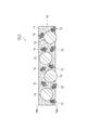
- FIG. 1 is a cross-sectional view showing an embodiment of an adhesive film.
- the adhesive film 1A (1) according to the embodiment includes a first adhesive layer 10.
- the first adhesive layer 10 contains a first adhesive component 11 and a first conductive particle 12 and a second conductive particle 13 dispersed in the first adhesive component 11.
- the first adhesive component 11 is composed of, for example, a material that is curable by heat or light, and is an epoxy adhesive, a radically curable adhesive, a thermoplastic adhesive containing polyurethane, a polyvinyl ester, or the like. It may be.
- the first adhesive component 11 may be made of a crosslinkable material because it is excellent in heat resistance and moisture resistance after adhesion.
- the epoxy adhesive contains an epoxy resin, which is a thermosetting resin, as a main component. Epoxy-based adhesives are preferably used because they can be cured in a short time, have good connection workability, and have excellent adhesiveness.
- the radical-curable adhesive has characteristics such as being superior in curability at a low temperature for a short time as compared with an epoxy-based adhesive, and is therefore appropriately used depending on the intended use.
- the epoxy adhesive contains, for example, an epoxy resin (thermosetting material) and a curing agent, and may further contain a thermoplastic resin, a coupling agent, a filler, and the like, if necessary.
- the epoxy resin examples include bisphenol A type epoxy resin, bisphenol F type epoxy resin, bisphenol S type epoxy resin, phenol novolac type epoxy resin, cresol novolac type epoxy resin, bisphenol A novolac type epoxy resin, and bisphenol F novolac type epoxy resin. , Alicyclic epoxy resin, glycidyl ester type epoxy resin, glycidylamine type epoxy resin, hydrantin type epoxy resin, isocyanurate type epoxy resin, aliphatic chain epoxy resin and the like. These epoxy resins may be halogenated, hydrogenated, or have a structure in which an acryloyl group or a methacryloyl group is added to the side chain. These epoxy resins are used alone or in combination of two or more.
- the curing agent is not particularly limited as long as it can cure the epoxy resin.
- an anionic polymerizable catalytic curing agent, a cationically polymerizable catalytic curing agent, a heavy addition type curing agent and the like can be used. Can be mentioned. Of these, an anionic or cationically polymerizable catalytic curing agent is preferable because it is excellent in quick curing property and does not require consideration of chemical equivalents.
- anionic or cationically polymerizable catalytic curing agents include imidazole, hydrazide, boron trifluoride-amine complex, onium salt (aromatic sulfonium salt, aromatic diazonium salt, aliphatic sulfonium salt, etc.), amineimide, and diamino. Examples thereof include maleonitrile, melamine and its derivatives, salts of polyamines, dicyandiamide and the like, and modified products thereof can also be used. Examples of the heavy addition type curing agent include polyamines, polymercaptans, polyphenols, acid anhydrides and the like.
- curing agents may be microencapsulated latent curing agents coated with a polymer substance such as polyurethane or polyester, a metal thin film such as nickel or copper, or an inorganic substance such as calcium silicate. .. Latent hardeners are preferred because they can extend the pot life.
- the curing agent may be used alone or in combination of two or more.
- the content of the curing agent may be 0.05 to 20 parts by mass with respect to 100 parts by mass of the total amount of the thermosetting material and the thermoplastic resin to be blended if necessary.
- the radical-curable adhesive contains, for example, a radical-polymerizable material and a radical polymerization initiator (also called a curing agent), and further contains a thermoplastic resin, a coupling agent, a filler, and the like, if necessary. It's okay.
- any substance having a functional group that is polymerized by radicals can be used without particular limitation.
- a radically polymerizable material such as an acrylate (including the corresponding methacrylate; the same applies hereinafter) compound, an acryloxy (including the corresponding metaacryloxy; the same applies hereinafter) compound, a maleimide compound, a citraconimide resin, and a nadiimide resin.
- radically polymerizable materials may be in the state of a monomer or an oligomer, or may be in the state of a mixture of a monomer and an oligomer.
- acrylate compound examples include methyl acrylate, ethyl acrylate, isopropyl acrylate, isobutyl acrylate, ethylene glycol diacrylate, diethylene glycol diacrylate, trimethyl propantriacrylate, tetramethylol methanetetraacrylate, 2-hydroxy-1,3-diacrylate.
- a radically polymerizable material such as an acrylate compound may be used together with a polymerization inhibitor such as hydroquinone or methyl ether hydroquinone, if necessary.
- the radically polymerizable material such as an acrylate compound preferably has at least one substituent such as a dicyclopentenyl group, a tricyclodecanyl group, or a triazine ring from the viewpoint of improving heat resistance.
- the radically polymerizable material other than the acrylate compound for example, the compound described in International Publication No. 2009/0638227 can be preferably used.
- the radically polymerizable material may be used alone or in combination of two or more.
- radical polymerization initiator for example, any compound that decomposes by heating or irradiation with light to generate free radicals can be used without particular limitation.
- Specific examples thereof include peroxide compounds and azo compounds. These compounds are appropriately selected according to the target connection temperature, connection time, pot life, and the like.
- radical polymerization initiator examples include diacyl peroxide, peroxydicarbonate, peroxyester, peroxyketal, dialkyl peroxide, hydroperoxide, silyl peroxide and the like.
- peroxyesters, dialkyl peroxides, hydroperoxides, silyl peroxides and the like are preferable, and peroxyesters capable of obtaining high reactivity are more preferable.
- the radical polymerization initiators for example, the compounds described in International Publication No. 2009/0638227 can be preferably used.
- the radical polymerization initiator may be used alone or in combination of two or more.
- the content of the radical polymerization initiator may be 0.1 parts by mass or more and 10 parts by mass or less with respect to 100 parts by mass of the total amount of the radically polymerizable material and the thermoplastic resin to be blended if necessary. It's okay.
- thermoplastic resin blended as necessary in the epoxy adhesive and the radical curable adhesive makes it easy to form the adhesive into a film, for example.
- thermoplastic resin examples include phenoxy resin, polyvinyl formal resin, polystyrene resin, polyvinyl butyral resin, polyester resin, polyamide resin, xylene resin, polyurethane resin, polyester urethane resin, phenol resin, terpene phenol resin and the like.
- the thermoplastic resin for example, the compound described in International Publication No. 2009/0638227 can be preferably used.
- phenoxy resin is preferable because it is excellent in adhesiveness, compatibility, heat resistance, mechanical strength and the like.
- the thermoplastic resin is used alone or in combination of two or more.
- the content of the thermoplastic resin When blended in an epoxy adhesive, the content of the thermoplastic resin may be 5 parts by mass or more and 80 parts by mass or less with respect to 100 parts by mass of the total amount of the thermoplastic resin and the thermosetting material. It's okay.
- the content of the thermoplastic resin When blended in a radical curable adhesive, the content of the thermoplastic resin may be 5 parts by mass or more and 80 parts by mass or less with respect to 100 parts by mass of the total amount of the thermoplastic resin and the radically polymerizable material. May be.
- the first adhesive component 11 is a thermal radical curable adhesive containing a thermoplastic resin, a radically polymerizable material liquid at 30 ° C., and a radical polymerization initiator.
- the thermal radical curable adhesive has a lower viscosity than the above-mentioned adhesive.
- the content of the radically polymerizable material in the thermally radical curable adhesive is 20 parts by mass or more, 30 parts by mass or more, or 40 parts by mass or more with respect to 100 parts by mass of the total amount of the thermoplastic resin and the radically polymerizable material. It may be 80 parts by mass or less.
- the first adhesive component 11 may be an epoxy-based adhesive containing a thermoplastic resin, a thermosetting material containing an epoxy resin liquid at 30 ° C., and a curing agent.
- the content of the epoxy resin in the epoxy adhesive is 20 parts by mass or more, 30 parts by mass or more, or 40 parts by mass or more with respect to 100 parts by mass of the total amount of the thermoplastic resin and the thermosetting material. It may be 80 parts by mass or less.
- the volume ratio of the first adhesive component 11 to the first adhesive layer 10 may be, for example, 55% by volume or more or 65% by volume or more based on the total volume of the first adhesive layer 10. It may be 95% by volume or less or 85% by volume or less.
- the first conductive particle 12 has a dendrite-like shape (also called a dendritic shape), and includes one main shaft and a plurality of branches that branch two-dimensionally or three-dimensionally from the main shaft.
- the first conductive particles 12 may be formed of a metal such as copper or silver, and may be, for example, silver-coated copper particles in which the copper particles are coated with silver.
- the first conductive particles 12 may be known, and specifically, for example, ACBY-2 (Mitsui Mining & Smelting Co., Ltd.), CE-1110 (Fukuda Metal Foil Powder Industry Co., Ltd.), #FSP (JX). Metal Co., Ltd.), # 51-R (JX Nippon Mining & Metal Co., Ltd.), etc.
- the first conductive particle 12 can be produced by a known method (for example, the method described in International Publication No. 2014/021037).
- the content of the first conductive particles 12 in the first adhesive layer 10 is based on the total volume of the first adhesive layer 10. From the viewpoint of further reducing the resistance of the connector, it is preferably 10% by volume or more, more preferably 20% by volume or more, still more preferably 30% by volume or more, and from the viewpoint of improving the adhesive strength of the adhesive film. It is preferably 60% by volume or less, more preferably 55% by volume or less, still more preferably 50% by volume or less.
- the second conductive particle 13 may have, for example, a non-conductive nuclei and a conductive layer provided on the nuclei.
- the core is made of a non-conductive material such as glass, ceramic, or resin, and is preferably made of resin.
- the resin include acrylic resin, styrene resin, silicone resin, polybutadiene resin, and copolymers of monomers constituting these resins.
- the average particle size of the nuclei is appropriately selected so that the average particle size of the second conductive particles 13 is in the range described later.
- the conductive layer is formed of, for example, gold, silver, copper, nickel, palladium or an alloy thereof. From the viewpoint of excellent conductivity, the conductive layer preferably contains at least one selected from gold, nickel and palladium, more preferably gold or palladium, and even more preferably gold.
- the conductive layer is formed, for example, by plating the core with the metal.
- the thickness of the conductive layer may be, for example, 10 nm or more and 400 nm or less.
- the average particle size of the second conductive particles 13 may be, for example, 10 ⁇ m or more, 20 ⁇ m or more, or 30 ⁇ m or more, and may be 50 ⁇ m or less, 45 ⁇ m or less, or 40 ⁇ m or less.
- the average particle size of the second conductive particle 13 and the nuclei constituting the second conductive particle 13 is measured by a particle size distribution measuring device (Microtrack (product name, Nikkiso Co., Ltd.)) using a laser diffraction / scattering method.
- the content of the second conductive particles 13 in the first adhesive layer 10 is based on the total volume of the first adhesive layer 10. It may be 2% by volume or more or 5% by volume or more, and may be 20% by volume or less or 10% by volume or less.
- the thickness of the first adhesive layer 10 may be, for example, 10 ⁇ m or more, 20 ⁇ m or more, or 30 ⁇ m or more, and may be 50 ⁇ m or less, 45 ⁇ m or less, or 40 ⁇ m or less.
- the thickness of the first adhesive layer 10 is the first in the one surface 10a of the first adhesive layer 10 where the first conductive particles 12 and the second conductive particles 13 do not protrude. It is defined as the thickness of the adhesive layer 10.
- the adhesive film 1A As shown in FIG. 1, a part of the plurality of first conductive particles 12 and the second conductive particles 13 contained in the first adhesive layer 10 (first adhesive).
- the first conductive particles 12 and the second conductive particles 13) existing in the vicinity of the one surface 10a of the layer 10 are arranged so as to protrude from the one surface 10a of the first adhesive layer 10.
- the first adhesive layer 10 supports, for example, a mixed solution containing the first conductive particles 12, the second conductive particles 13, and the first adhesive component 11 dissolved in a solvent.
- the first conductive particles 12 and the second conductive particles 13 are formed in the first adhesive layer 10 as the boiling point of the solvent used at this time is lower.
- it becomes easy to protrude from the surface 10a the higher the drying condition for removing the solvent and the shorter the time, the easier it is for the first conductive particles 12 and the second conductive particles 13 to protrude from one surface 10a of the first adhesive layer 10.
- both the first conductive particles 12 and the second conductive particles 13 are arranged so as to protrude from one surface 10a of the first adhesive layer 10, but the first adhesive layer.
- a part of the plurality of conductive particles contained in 10 may be arranged so as to protrude from one surface 10a of the first adhesive layer 10.
- only the first conductive particles 12 need to be arranged so as to protrude from one surface 10a of the first adhesive layer 10. It may be arranged so as to project from one surface 10a of the layer 10, or only the second conductive particles 13 may be arranged so as to project from one surface 10a of the first adhesive layer 10.
- the adhesive film 1A includes only one layer of the first adhesive layer 10, but in another embodiment, the adhesive film 1 may include two or more layers.
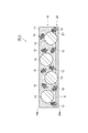
- FIG. 2 is a cross-sectional view showing another embodiment of the adhesive film 1. As shown in FIG. 2, the adhesive film 1B (1) according to another embodiment is provided on one surface 10a of the first adhesive layer 10 in addition to the above-mentioned first adhesive layer 10. The second adhesive layer 20 may be further provided.
- the second adhesive layer 20 contains, for example, the second adhesive component 21.
- the second adhesive layer 20 does not have to contain conductive particles.
- the second adhesive component 21 may be composed of a material selected from the materials exemplified as the first adhesive component 11, but is different from the first adhesive component (having a different composition). ..
- the second adhesive layer 20 (second adhesive component 21) is preferably the first adhesive layer 10 (second adhesive layer 10) from the viewpoint of excellent adhesiveness when the adhesive film 1B is attached to the object to be adhered. It has an adhesive strength higher than the adhesive strength of the adhesive component 11) of 1.
- the melt viscosity of the second adhesive layer 20 at 25 ° C. is preferably lower than the melt viscosity of the first adhesive layer 10 at 25 ° C.
- the melt viscosity of the first adhesive layer 10 at 25 ° C. may be, for example, 1 ⁇ 10 4 Pa ⁇ s or more, 5 ⁇ 10 4 Pa ⁇ s or more, or 1 ⁇ 10 5 Pa ⁇ s or more.
- the melt viscosity of the second adhesive layer 20 at 25 ° C. may be less than 1 ⁇ 10 4 Pa ⁇ s, 7 ⁇ 10 4 Pa ⁇ s or less, or 5 ⁇ 10 5 Pa ⁇ s or less.
- the melt viscosity of each adhesive layer is measured by laminating each adhesive layer so as to have a thickness of 500 ⁇ m, and the measurement sample is cut into 10 mm ⁇ 10 mm (thickness 500 ⁇ m) and film melt viscosity measuring device (for example, 500 ⁇ m). It is measured using a product name: ARES-G2, manufactured by TA Instruments Co., Ltd., under the conditions of measurement frequency: 10 Hz and heating rate: 10 ° C./min.
- the thickness of the second adhesive layer 20 is preferably thinner than the thickness of the first adhesive layer 10 from the viewpoint of more preferably obtaining the effect of blocking resistance.
- the thickness of the second adhesive layer 20 may be, for example, 0.5 ⁇ m or more, 1 ⁇ m or more, 1.5 ⁇ m or more, or 2 ⁇ m or more, preferably 5 ⁇ m or less, more preferably 4 ⁇ m or less, still more preferably 3 ⁇ m. It is as follows.
- the thickness of the second adhesive layer 20 is the second thickness of the one surface 10a of the first adhesive layer 10 where the first conductive particles 12 and the second conductive particles 13 do not protrude. It is defined as the thickness of the adhesive layer 20.
- the adhesive film 1B is provided with the second adhesive layer 20, so that excellent blocking resistance can be obtained when used in the form of a reel body (details are as follows). Will be described later).
- both the first conductive particles 12 and the second conductive particles 13 are moved from the interface S between the first adhesive layer 10 and the second adhesive layer 20 to the second adhesive layer 20 side.
- a part of the plurality of conductive particles contained in the first adhesive layer 10 is second from the interface S between the first adhesive layer 10 and the second adhesive layer 20. It suffices to be arranged so as to project toward the adhesive layer 20 side.
- only the first conductive particles 12 are secondly bonded from the interface S between the first adhesive layer 10 and the second adhesive layer 20. It may be arranged so as to project toward the agent layer 20, and only the second conductive particles 13 are arranged from the interface S between the first adhesive layer 10 and the second adhesive layer 20 to the second adhesive layer 20. It may be arranged so as to protrude to the side.
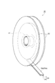
- FIG. 3 is a perspective view showing an embodiment of the reel body.
- the reel body 30 according to the embodiment is formed on a tubular winding core 31, a disk-shaped side plate 32 provided on both end surfaces of the winding core 31 in the axial direction, and a winding core 31. It is provided with a long adhesive tape 33 that has been wound into a heavy body.
- the adhesive tape 33 includes a long support 34 and an adhesive film 1.
- the adhesive film 1 has a long shape substantially the same as that of the support 34.
- the length of the support 34 may be, for example, 1 to 400 m.
- the thickness of the support 34 may be, for example, 4 to 200 ⁇ m.
- the width of the support 34 may be, for example, 0.5 to 30 mm.
- the support 34 includes, for example, polyethylene terephthalate, polyethylene naphthalate, polyethylene isophthalate, polybutylene terephthalate, polyolefin, polyacetate, polycarbonate, polyphenylene sulfide, polyamide, ethylene / vinyl acetate copolymer, polyvinyl chloride, polyvinylidene chloride, and the like. It may be made of a polymer such as a synthetic rubber type or a liquid crystal polymer.
- the other surface of the first adhesive layer 10 (the surface opposite to the surface on which the first conductive particles 12 and the second conductive particles 13 protrude) is the support 34. It is provided on the support 34 so as to face the side.
- the adhesive film 1A is one surface of the first adhesive layer 10 (first conductive particles 12 and second conductive particles).
- a surface on which 13 protrudes) 10a is provided on the support 34 so as to face the side opposite to the support 34.
- the adhesive film 1 is the adhesive film 1B shown in FIG. 2
- the surface 20a of the second adhesive layer 20 opposite to the first adhesive layer 10 is the support 34. Is provided on the support 34 so as to face the opposite side.
- the adhesive tape in the reel body 30 is one surface of the first adhesive layer 10 (first conductive particles 12 and second conductive particles).
- the surface on which 13 protrudes) 10a is in contact with the back surface (the surface opposite to the surface on which the first adhesive layer 10 is provided) of the support 34 in the adhesive tape wound inside one roll. It is rolled up. At this time, since the first conductive particles 12 and the second conductive particles 13 protrude on the one side 10a side of the first adhesive layer 10, the first adhesive component 11 is wound one roll inward.
- the protruding first conductive particles 12 and the second conductive particles 13 are one surface 10a of the first adhesive layer 10 and the support. It acts like a spacer between the back surface 34a of the 34 and the distance between the two is easily maintained). Therefore, in the reel body 30 including the adhesive film 1A, even if the adhesive strength of the adhesive film 1 (first adhesive component 11) is the same, excellent blocking resistance (particularly, winding inside one roll). Blocking resistance of the support 34 to the back surface 34a of the adhesive tape 33A) is obtained. Such an effect can be similarly exhibited even when the adhesive force of the adhesive film 1 (first adhesive component 11) is increased.
- the adhesive film 1 is the adhesive film 1B shown in FIG. 2, the reason is not clear, but the excellent blocking resistance as described above can be obtained.
- the adhesive film 1A is provided with the second adhesive layer 20, so that the adhesive film 1A has better adhesiveness than the adhesive film 1A. Be done.
- the adhesive film 1 and the adhesive tape 33 described above are suitably used as an adhesive for electrically connecting electronic members to each other.
- the type of electronic member is not particularly limited.
- the electronic member includes, for example, a substrate and an electrode 9 formed on one surface of the substrate.
- the substrate may be, for example, a substrate made of glass, ceramic, polyimide, polycarbonate, polyester, polyether sulfone, or the like.
- the electrode may be, for example, an electrode formed of gold, silver, copper, tin, aluminum, ruthenium, rhodium, palladium, osmium, iridium, platinum, indium tin oxide (ITO) or the like.
- dendrite-like conductive particle As the first conductive particle, dendrite-like conductive particle (silver-coated copper particle, product name: ACBY-2, manufactured by Mitsui Mining & Smelting Co., Ltd.) was used.
- the second conductive particle was prepared by the following procedure. First, benzoyl peroxide was added as a polymerization initiator to a mixed solution of divinylbenzene, styrene monomer, and butyl methacrylate, and heated with uniform stirring at high speed to carry out a polymerization reaction to obtain a fine particle dispersion. The fine particle dispersion was filtered and dried under reduced pressure to obtain a block which is an aggregate of fine particles. Further, by pulverizing this block body, a nuclei having an average particle size of 20 ⁇ m was prepared.
- a palladium catalyst (manufactured by Muromachi Technos Co., Ltd., product name: MK-2605) is supported on the surface of the above nucleus and activated with an accelerator (manufactured by Muromachi Technos Co., Ltd., product name: MK-370).
- the nuclei were put into a mixed solution of a nickel sulfate aqueous solution, a sodium hypophosphite aqueous solution and a sodium tartrate aqueous solution heated to 60 ° C., and an electroless plating pre-step was performed. The mixture was stirred for 20 minutes and it was confirmed that hydrogen foaming stopped.
- a mixed solution was obtained by dispersing 45 parts by volume of the first conductive particles and 15 parts by volume of the second conductive particles with respect to 100 parts by volume of the adhesive component.
- the obtained mixed solution was applied onto a fluororesin film (support) having a thickness of 80 ⁇ m, and the solvent was removed by hot air drying at 70 ° C. for 10 minutes to form a fluororesin film having a thickness of 25 ⁇ m.
- An adhesive film (adhesive tape) having a first adhesive layer was obtained.
- Example 1 An adhesive film was obtained in the same manner as in Comparative Example 1 except that the drying conditions for removing the solvent from the mixed solution coated on the fluororesin film were changed to hot air drying at 90 ° C. for 2 minutes.
- Example 2 When obtaining the mixed solution, 45 parts by volume of the first conductive particles and 15 parts by volume of the second conductive particles were dispersed in 100 parts by volume of the adhesive component, and 30 parts by volume of acetone (boiling point 56. An adhesive film was obtained in the same manner as in Comparative Example 1 except that 1 ° C.) was further added.
- Adhesive tapes (length: 100 m) of Examples 1 and 2 and Comparative Example 1 in which a 3-inch ABS core (manufactured by Showa Maru Cylinder Co., Ltd.) was used as a winding core and cut to a width of 5 mm with respect to the winding core. Wrapped around. Subsequently, disc-shaped polystyrene side plates (diameter: 180 mm, thickness: 1 mm) were fitted to both ends of the winding core to prepare a reel body.
- a 3-inch ABS core manufactured by Showa Maru Cylinder Co., Ltd.
- a SUS plate was placed in a constant temperature bath (manufactured by AS ONE Corporation, product name: small incubator IC-150MA) set at 30 ° C., and the produced reel body was placed horizontally on the SUS plate (reel body). The side plate and the SUS plate were parallel to each other) and allowed to stand for 72 hours.
- the blocking resistance after the horizontal placement test was evaluated according to the following criteria according to the state when the adhesive tape was to be pulled out from the reel body (winding core) at 25 ° C. after standing. The results are shown in Table 1.
- B Although the adhesive film was partially peeled off from the support, the adhesive tape could be pulled out.
- C The adhesive tape could not be pulled out.
- connection resistance of each of the adhesive films of Examples 1 and 2 and Comparative Example 1 was evaluated by the following procedure. The results are shown in Table 1.
- FIG. 4A is a top view of the resistance measurement sample 40
- FIG. 4B is a cross-sectional view taken along the line IVb-IVb of FIG. 4A.
- a polyimide film 42 (size: 30 mm ⁇ 30 mm, thickness: 25 ⁇ m) was placed on a copper foil 41 (size: 35 mm ⁇ 35 mm, thickness: 25 ⁇ m).
- the aluminum foil 44 (size: 15 mm ⁇ 20 mm, thickness) is passed through each of the adhesive films 43 (size: 15 mm ⁇ 3 mm) of Examples 1 and 2 and Comparative Example 1. : 25 ⁇ m) was connected.
- the current and voltage between the copper foil 41 and the aluminum foil 44 were measured with an ammeter A and a voltmeter V, respectively, and the resistance value (initial) was calculated.
- the resistance measurement sample 40 prepared as described above is held at ⁇ 20 ° C. for 30 minutes using TSA-43EL manufactured by ESPEC, heated to 100 ° C. over 10 minutes, and held at 100 ° C. for 30 minutes. The temperature was lowered to ⁇ 20 ° C. over 10 minutes, which was subjected to a cycle test in which 250 cycles of heat cycles were repeated. The resistance value (after the cycle test) was measured for each of the resistance measurement samples 40 after the cycle test in the same manner as described above.
- the adhesiveness was evaluated according to the following criteria according to the state of the adhesive film when the support was attempted to be peeled off from the adhesive film.
- Example 3 An adhesive film was obtained in the same manner as in Comparative Example 2 except that the drying conditions for removing the solvent from the mixed solution coated on the fluororesin film were changed to hot air drying at 90 ° C. for 2 minutes.
- Example 5 A second adhesive layer was provided on the surface of the first adhesive layer obtained in Example 2 on the opposite side of the fluororesin film in the same manner as in Example 4.
- Example 3 When the appearance of each of the adhesive films (adhesive tapes) of Examples 3 to 5 and Comparative Example 2 was observed in the same manner as described above, in Example 3, the first conductive particles and the second conductive particles were observed. It was confirmed that the particles protruded from the first adhesive layer, whereas in Comparative Example 2, the first conductive particles and the second conductive particles protruded from the first adhesive layer. Not confirmed. Further, in Examples 4 and 5, the surface of the second adhesive layer has an uneven shape that is considered to be derived from the first conductive particles and the second conductive particles protruding from the first adhesive layer. It was confirmed that there was.
- the adhesive strength, the blocking resistance, and the connection resistance were evaluated in the same manner as described above. Further, with respect to each of the adhesive films of Examples 3 to 5, the adhesiveness was evaluated in the same manner as described above. However, the adhesive films of Examples 3 to 5 and Comparative Example 2 are more likely to cause a blocking phenomenon due to their higher adhesive strength than the adhesive films of Examples 1 and 2 and Comparative Example 1. Therefore, in the evaluation of blocking resistance, the time for allowing the reel body to stand in the constant temperature bath was changed from 72 hours to 24 hours.
- Adhesive film 10 ... First adhesive layer, 10a ... One side of the first adhesive layer, 11 ... First adhesive component, 12 ... First conductive particles, 13 ... Second conductive particles, 20 ... second adhesive layer, 30 ... reel body, 31 ... core, 33 ... adhesive tape, 34 ... support.
Landscapes
- Chemical & Material Sciences (AREA)
- Organic Chemistry (AREA)
- Inorganic Chemistry (AREA)
- Adhesives Or Adhesive Processes (AREA)
- Adhesive Tapes (AREA)
Priority Applications (6)
| Application Number | Priority Date | Filing Date | Title |
|---|---|---|---|
| JP2022504438A JP7794121B2 (ja) | 2020-03-04 | 2021-03-03 | 接着剤フィルム、及びリール体 |
| CN202180017869.5A CN115210331B (zh) | 2020-03-04 | 2021-03-03 | 黏合剂膜及卷轴体 |
| US17/905,415 US20230163489A1 (en) | 2020-03-04 | 2021-03-03 | Adhesive film and reel body |
| KR1020227032129A KR102958947B1 (ko) | 2020-03-04 | 2021-03-03 | 접착제 필름, 및 릴체 |
| US19/083,439 US20250219304A1 (en) | 2020-03-04 | 2025-03-19 | Reel body |
| JP2025177660A JP2026002934A (ja) | 2020-03-04 | 2025-10-22 | リール体 |
Applications Claiming Priority (2)
| Application Number | Priority Date | Filing Date | Title |
|---|---|---|---|
| JP2020037070 | 2020-03-04 | ||
| JP2020-037070 | 2020-03-04 |
Related Child Applications (2)
| Application Number | Title | Priority Date | Filing Date |
|---|---|---|---|
| US17/905,415 A-371-Of-International US20230163489A1 (en) | 2020-03-04 | 2021-03-03 | Adhesive film and reel body |
| US19/083,439 Division US20250219304A1 (en) | 2020-03-04 | 2025-03-19 | Reel body |
Publications (1)
| Publication Number | Publication Date |
|---|---|
| WO2021177375A1 true WO2021177375A1 (ja) | 2021-09-10 |
Family
ID=77613432
Family Applications (1)
| Application Number | Title | Priority Date | Filing Date |
|---|---|---|---|
| PCT/JP2021/008264 Ceased WO2021177375A1 (ja) | 2020-03-04 | 2021-03-03 | 接着剤フィルム、及びリール体 |
Country Status (5)
| Country | Link |
|---|---|
| US (2) | US20230163489A1 (https=) |
| JP (2) | JP7794121B2 (https=) |
| CN (1) | CN115210331B (https=) |
| TW (1) | TWI878478B (https=) |
| WO (1) | WO2021177375A1 (https=) |
Citations (3)
| Publication number | Priority date | Publication date | Assignee | Title |
|---|---|---|---|---|
| JP2012102278A (ja) * | 2010-11-12 | 2012-05-31 | Sony Chemical & Information Device Corp | リール体及びその製造方法、接着フィルムの平坦化方法 |
| JP2018137237A (ja) * | 2012-08-24 | 2018-08-30 | デクセリアルズ株式会社 | 異方性導電フィルムの製造方法及び異方性導電フィルム |
| WO2019131904A1 (ja) * | 2017-12-28 | 2019-07-04 | 日立化成株式会社 | 接続構造体及びその製造方法 |
Family Cites Families (9)
| Publication number | Priority date | Publication date | Assignee | Title |
|---|---|---|---|---|
| JP4887700B2 (ja) * | 2005-09-09 | 2012-02-29 | 住友ベークライト株式会社 | 異方導電性フィルムおよび電子・電機機器 |
| WO2009133901A1 (ja) * | 2008-04-28 | 2009-11-05 | 日立化成工業株式会社 | 回路接続材料、フィルム状接着剤、接着剤リール及び回路接続構造体 |
| US20180017715A1 (en) * | 2015-01-27 | 2018-01-18 | Nitto Denko Corporation | Transparent conductive film |
| KR20190035956A (ko) * | 2015-02-27 | 2019-04-03 | 데쿠세리아루즈 가부시키가이샤 | 릴체, 필름 연결체, 필름 권취 장착체 및 필름 연결체의 제조 방법 |
| KR20190010879A (ko) * | 2016-09-13 | 2019-01-31 | 데쿠세리아루즈 가부시키가이샤 | 필러 함유 필름 |
| JP7035370B2 (ja) * | 2016-10-31 | 2022-03-15 | デクセリアルズ株式会社 | フィラー含有フィルム |
| JP7039883B2 (ja) * | 2016-12-01 | 2022-03-23 | デクセリアルズ株式会社 | 異方性導電フィルム |
| KR102519781B1 (ko) * | 2016-12-01 | 2023-04-10 | 데쿠세리아루즈 가부시키가이샤 | 이방성 도전 필름 |
| US11319466B2 (en) * | 2017-02-17 | 2022-05-03 | Showa Denko Materials Co., Ltd. | Adhesive film |
-
2021
- 2021-03-03 US US17/905,415 patent/US20230163489A1/en not_active Abandoned
- 2021-03-03 WO PCT/JP2021/008264 patent/WO2021177375A1/ja not_active Ceased
- 2021-03-03 CN CN202180017869.5A patent/CN115210331B/zh active Active
- 2021-03-03 JP JP2022504438A patent/JP7794121B2/ja active Active
- 2021-03-04 TW TW110107694A patent/TWI878478B/zh active
-
2025
- 2025-03-19 US US19/083,439 patent/US20250219304A1/en active Pending
- 2025-10-22 JP JP2025177660A patent/JP2026002934A/ja active Pending
Patent Citations (3)
| Publication number | Priority date | Publication date | Assignee | Title |
|---|---|---|---|---|
| JP2012102278A (ja) * | 2010-11-12 | 2012-05-31 | Sony Chemical & Information Device Corp | リール体及びその製造方法、接着フィルムの平坦化方法 |
| JP2018137237A (ja) * | 2012-08-24 | 2018-08-30 | デクセリアルズ株式会社 | 異方性導電フィルムの製造方法及び異方性導電フィルム |
| WO2019131904A1 (ja) * | 2017-12-28 | 2019-07-04 | 日立化成株式会社 | 接続構造体及びその製造方法 |
Also Published As
| Publication number | Publication date |
|---|---|
| CN115210331A (zh) | 2022-10-18 |
| JPWO2021177375A1 (https=) | 2021-09-10 |
| JP2026002934A (ja) | 2026-01-08 |
| US20250219304A1 (en) | 2025-07-03 |
| US20230163489A1 (en) | 2023-05-25 |
| TW202136446A (zh) | 2021-10-01 |
| KR20220145856A (ko) | 2022-10-31 |
| JP7794121B2 (ja) | 2026-01-06 |
| CN115210331B (zh) | 2024-09-17 |
| TWI878478B (zh) | 2025-04-01 |
Similar Documents
| Publication | Publication Date | Title |
|---|---|---|
| US20220363958A1 (en) | Adhesive composition | |
| JP7347576B2 (ja) | 接着剤フィルム | |
| JP7314801B2 (ja) | 接続構造体及びその製造方法 | |
| JP2024160304A (ja) | 接着剤フィルム | |
| WO2021177375A1 (ja) | 接着剤フィルム、及びリール体 | |
| KR102958947B1 (ko) | 접착제 필름, 및 릴체 | |
| TWI814761B (zh) | 接著劑膜 | |
| US12227683B2 (en) | Connector production method and adhesive film |
Legal Events
| Date | Code | Title | Description |
|---|---|---|---|
| 121 | Ep: the epo has been informed by wipo that ep was designated in this application |
Ref document number: 21764819 Country of ref document: EP Kind code of ref document: A1 |
|
| ENP | Entry into the national phase |
Ref document number: 2022504438 Country of ref document: JP Kind code of ref document: A |
|
| ENP | Entry into the national phase |
Ref document number: 20227032129 Country of ref document: KR Kind code of ref document: A |
|
| NENP | Non-entry into the national phase |
Ref country code: DE |
|
| 32PN | Ep: public notification in the ep bulletin as address of the adressee cannot be established |
Free format text: NOTING OF LOSS OF RIGHTS PURSUANT TO RULE 112(1) EPC (EPO FORM 1205A DATED 25/11/2022) |
|
| 122 | Ep: pct application non-entry in european phase |
Ref document number: 21764819 Country of ref document: EP Kind code of ref document: A1 |