WO2021177375A1 - Adhesive film and reel body - Google Patents
Adhesive film and reel body Download PDFInfo
- Publication number
- WO2021177375A1 WO2021177375A1 PCT/JP2021/008264 JP2021008264W WO2021177375A1 WO 2021177375 A1 WO2021177375 A1 WO 2021177375A1 JP 2021008264 W JP2021008264 W JP 2021008264W WO 2021177375 A1 WO2021177375 A1 WO 2021177375A1
- Authority
- WO
- WIPO (PCT)
- Prior art keywords
- adhesive
- conductive particles
- adhesive layer
- adhesive film
- conductive
- Prior art date
Links
- 239000002313 adhesive film Substances 0.000 title claims abstract description 88
- 239000002245 particle Substances 0.000 claims abstract description 123
- 239000012790 adhesive layer Substances 0.000 claims abstract description 110
- 239000000853 adhesive Substances 0.000 claims abstract description 76
- 230000001070 adhesive effect Effects 0.000 claims abstract description 76
- 239000010410 layer Substances 0.000 claims abstract description 14
- 239000002390 adhesive tape Substances 0.000 claims description 22
- 238000004804 winding Methods 0.000 claims description 13
- 210000001787 dendrite Anatomy 0.000 abstract 1
- -1 glycidyl ester Chemical class 0.000 description 23
- 230000000052 comparative effect Effects 0.000 description 22
- 239000000463 material Substances 0.000 description 22
- 230000000903 blocking effect Effects 0.000 description 21
- 239000003822 epoxy resin Substances 0.000 description 21
- 229920000647 polyepoxide Polymers 0.000 description 21
- 239000003795 chemical substances by application Substances 0.000 description 19
- 229920005992 thermoplastic resin Polymers 0.000 description 16
- RYGMFSIKBFXOCR-UHFFFAOYSA-N Copper Chemical compound [Cu] RYGMFSIKBFXOCR-UHFFFAOYSA-N 0.000 description 13
- 239000000047 product Substances 0.000 description 12
- 229920005989 resin Polymers 0.000 description 12
- 239000011347 resin Substances 0.000 description 12
- KDLHZDBZIXYQEI-UHFFFAOYSA-N Palladium Chemical compound [Pd] KDLHZDBZIXYQEI-UHFFFAOYSA-N 0.000 description 10
- 239000010408 film Substances 0.000 description 10
- 239000011259 mixed solution Substances 0.000 description 9
- 229920006287 phenoxy resin Polymers 0.000 description 9
- 239000013034 phenoxy resin Substances 0.000 description 9
- 239000002904 solvent Substances 0.000 description 9
- 150000001875 compounds Chemical class 0.000 description 7
- 229910052802 copper Inorganic materials 0.000 description 7
- 239000010949 copper Substances 0.000 description 7
- 238000005259 measurement Methods 0.000 description 7
- 238000000034 method Methods 0.000 description 7
- 239000000203 mixture Substances 0.000 description 7
- 239000007870 radical polymerization initiator Substances 0.000 description 7
- 239000000243 solution Substances 0.000 description 7
- XEKOWRVHYACXOJ-UHFFFAOYSA-N Ethyl acetate Chemical compound CCOC(C)=O XEKOWRVHYACXOJ-UHFFFAOYSA-N 0.000 description 6
- PXHVJJICTQNCMI-UHFFFAOYSA-N Nickel Chemical compound [Ni] PXHVJJICTQNCMI-UHFFFAOYSA-N 0.000 description 6
- BQCADISMDOOEFD-UHFFFAOYSA-N Silver Chemical compound [Ag] BQCADISMDOOEFD-UHFFFAOYSA-N 0.000 description 6
- YXFVVABEGXRONW-UHFFFAOYSA-N Toluene Chemical compound CC1=CC=CC=C1 YXFVVABEGXRONW-UHFFFAOYSA-N 0.000 description 6
- 229920006332 epoxy adhesive Polymers 0.000 description 6
- UHESRSKEBRADOO-UHFFFAOYSA-N ethyl carbamate;prop-2-enoic acid Chemical compound OC(=O)C=C.CCOC(N)=O UHESRSKEBRADOO-UHFFFAOYSA-N 0.000 description 6
- 238000011156 evaluation Methods 0.000 description 6
- 229910052751 metal Inorganic materials 0.000 description 6
- 229910052709 silver Inorganic materials 0.000 description 6
- 239000004332 silver Substances 0.000 description 6
- 229920001187 thermosetting polymer Polymers 0.000 description 6
- 229910052782 aluminium Inorganic materials 0.000 description 5
- XAGFODPZIPBFFR-UHFFFAOYSA-N aluminium Chemical compound [Al] XAGFODPZIPBFFR-UHFFFAOYSA-N 0.000 description 5
- 239000011889 copper foil Substances 0.000 description 5
- 239000011888 foil Substances 0.000 description 5
- PCHJSUWPFVWCPO-UHFFFAOYSA-N gold Chemical compound [Au] PCHJSUWPFVWCPO-UHFFFAOYSA-N 0.000 description 5
- 229910052737 gold Inorganic materials 0.000 description 5
- 239000010931 gold Substances 0.000 description 5
- 239000000155 melt Substances 0.000 description 5
- 229910052763 palladium Inorganic materials 0.000 description 5
- 239000007787 solid Substances 0.000 description 5
- 239000000126 substance Substances 0.000 description 5
- 229910019142 PO4 Inorganic materials 0.000 description 4
- IISBACLAFKSPIT-UHFFFAOYSA-N bisphenol A Chemical compound C=1C=C(O)C=CC=1C(C)(C)C1=CC=C(O)C=C1 IISBACLAFKSPIT-UHFFFAOYSA-N 0.000 description 4
- PXKLMJQFEQBVLD-UHFFFAOYSA-N bisphenol F Chemical compound C1=CC(O)=CC=C1CC1=CC=C(O)C=C1 PXKLMJQFEQBVLD-UHFFFAOYSA-N 0.000 description 4
- 238000009835 boiling Methods 0.000 description 4
- 230000003197 catalytic effect Effects 0.000 description 4
- 238000001035 drying Methods 0.000 description 4
- 238000010438 heat treatment Methods 0.000 description 4
- 239000002184 metal Substances 0.000 description 4
- 229920003986 novolac Polymers 0.000 description 4
- 239000010452 phosphate Substances 0.000 description 4
- 239000000758 substrate Substances 0.000 description 4
- 239000004593 Epoxy Substances 0.000 description 3
- PPBRXRYQALVLMV-UHFFFAOYSA-N Styrene Chemical compound C=CC1=CC=CC=C1 PPBRXRYQALVLMV-UHFFFAOYSA-N 0.000 description 3
- 125000000129 anionic group Chemical group 0.000 description 3
- 239000007864 aqueous solution Substances 0.000 description 3
- 239000010419 fine particle Substances 0.000 description 3
- 238000007602 hot air drying Methods 0.000 description 3
- RAXXELZNTBOGNW-UHFFFAOYSA-N imidazole Natural products C1=CNC=N1 RAXXELZNTBOGNW-UHFFFAOYSA-N 0.000 description 3
- 238000005065 mining Methods 0.000 description 3
- 239000000178 monomer Substances 0.000 description 3
- 229910052759 nickel Inorganic materials 0.000 description 3
- 238000007747 plating Methods 0.000 description 3
- 229920000728 polyester Polymers 0.000 description 3
- 229920001721 polyimide Polymers 0.000 description 3
- MYRTYDVEIRVNKP-UHFFFAOYSA-N 1,2-Divinylbenzene Chemical compound C=CC1=CC=CC=C1C=C MYRTYDVEIRVNKP-UHFFFAOYSA-N 0.000 description 2
- LEJBBGNFPAFPKQ-UHFFFAOYSA-N 2-(2-prop-2-enoyloxyethoxy)ethyl prop-2-enoate Chemical compound C=CC(=O)OCCOCCOC(=O)C=C LEJBBGNFPAFPKQ-UHFFFAOYSA-N 0.000 description 2
- KUDUQBURMYMBIJ-UHFFFAOYSA-N 2-prop-2-enoyloxyethyl prop-2-enoate Chemical compound C=CC(=O)OCCOC(=O)C=C KUDUQBURMYMBIJ-UHFFFAOYSA-N 0.000 description 2
- KWSLGOVYXMQPPX-UHFFFAOYSA-N 5-[3-(trifluoromethyl)phenyl]-2h-tetrazole Chemical compound FC(F)(F)C1=CC=CC(C2=NNN=N2)=C1 KWSLGOVYXMQPPX-UHFFFAOYSA-N 0.000 description 2
- CSCPPACGZOOCGX-UHFFFAOYSA-N Acetone Chemical compound CC(C)=O CSCPPACGZOOCGX-UHFFFAOYSA-N 0.000 description 2
- NIXOWILDQLNWCW-UHFFFAOYSA-M Acrylate Chemical compound [O-]C(=O)C=C NIXOWILDQLNWCW-UHFFFAOYSA-M 0.000 description 2
- SOGAXMICEFXMKE-UHFFFAOYSA-N Butylmethacrylate Chemical compound CCCCOC(=O)C(C)=C SOGAXMICEFXMKE-UHFFFAOYSA-N 0.000 description 2
- UFHFLCQGNIYNRP-UHFFFAOYSA-N Hydrogen Chemical compound [H][H] UFHFLCQGNIYNRP-UHFFFAOYSA-N 0.000 description 2
- QIGBRXMKCJKVMJ-UHFFFAOYSA-N Hydroquinone Chemical compound OC1=CC=C(O)C=C1 QIGBRXMKCJKVMJ-UHFFFAOYSA-N 0.000 description 2
- BAPJBEWLBFYGME-UHFFFAOYSA-N Methyl acrylate Chemical compound COC(=O)C=C BAPJBEWLBFYGME-UHFFFAOYSA-N 0.000 description 2
- ATUOYWHBWRKTHZ-UHFFFAOYSA-N Propane Chemical compound CCC ATUOYWHBWRKTHZ-UHFFFAOYSA-N 0.000 description 2
- 239000000919 ceramic Substances 0.000 description 2
- 229920001577 copolymer Polymers 0.000 description 2
- 239000007822 coupling agent Substances 0.000 description 2
- 239000006185 dispersion Substances 0.000 description 2
- 230000000694 effects Effects 0.000 description 2
- 238000007772 electroless plating Methods 0.000 description 2
- 150000002148 esters Chemical class 0.000 description 2
- 239000000945 filler Substances 0.000 description 2
- 238000005187 foaming Methods 0.000 description 2
- 239000011521 glass Substances 0.000 description 2
- LNEPOXFFQSENCJ-UHFFFAOYSA-N haloperidol Chemical compound C1CC(O)(C=2C=CC(Cl)=CC=2)CCN1CCCC(=O)C1=CC=C(F)C=C1 LNEPOXFFQSENCJ-UHFFFAOYSA-N 0.000 description 2
- 239000001257 hydrogen Substances 0.000 description 2
- 229910052739 hydrogen Inorganic materials 0.000 description 2
- ZFSLODLOARCGLH-UHFFFAOYSA-N isocyanuric acid Chemical compound OC1=NC(O)=NC(O)=N1 ZFSLODLOARCGLH-UHFFFAOYSA-N 0.000 description 2
- 239000007788 liquid Substances 0.000 description 2
- LGQLOGILCSXPEA-UHFFFAOYSA-L nickel sulfate Chemical compound [Ni+2].[O-]S([O-])(=O)=O LGQLOGILCSXPEA-UHFFFAOYSA-L 0.000 description 2
- 229910000363 nickel(II) sulfate Inorganic materials 0.000 description 2
- 150000002978 peroxides Chemical class 0.000 description 2
- 239000005011 phenolic resin Substances 0.000 description 2
- BASFCYQUMIYNBI-UHFFFAOYSA-N platinum Chemical compound [Pt] BASFCYQUMIYNBI-UHFFFAOYSA-N 0.000 description 2
- 229920000768 polyamine Polymers 0.000 description 2
- 229920000515 polycarbonate Polymers 0.000 description 2
- 239000004417 polycarbonate Substances 0.000 description 2
- 229920000642 polymer Polymers 0.000 description 2
- 238000006116 polymerization reaction Methods 0.000 description 2
- 229920002635 polyurethane Polymers 0.000 description 2
- 239000004814 polyurethane Substances 0.000 description 2
- 150000003839 salts Chemical class 0.000 description 2
- 229910001379 sodium hypophosphite Inorganic materials 0.000 description 2
- KYPOHTVBFVELTG-UPHRSURJSA-N (z)-but-2-enedinitrile Chemical compound N#C\C=C/C#N KYPOHTVBFVELTG-UPHRSURJSA-N 0.000 description 1
- FYRCDEARNUVZRG-UHFFFAOYSA-N 1,1,5-trimethyl-3,3-bis(2-methylpentan-2-ylperoxy)cyclohexane Chemical compound CCCC(C)(C)OOC1(OOC(C)(C)CCC)CC(C)CC(C)(C)C1 FYRCDEARNUVZRG-UHFFFAOYSA-N 0.000 description 1
- BEQKKZICTDFVMG-UHFFFAOYSA-N 1,2,3,4,6-pentaoxepane-5,7-dione Chemical compound O=C1OOOOC(=O)O1 BEQKKZICTDFVMG-UHFFFAOYSA-N 0.000 description 1
- JYEUMXHLPRZUAT-UHFFFAOYSA-N 1,2,3-triazine Chemical group C1=CN=NN=C1 JYEUMXHLPRZUAT-UHFFFAOYSA-N 0.000 description 1
- QTWJRLJHJPIABL-UHFFFAOYSA-N 2-methylphenol;3-methylphenol;4-methylphenol Chemical compound CC1=CC=C(O)C=C1.CC1=CC=CC(O)=C1.CC1=CC=CC=C1O QTWJRLJHJPIABL-UHFFFAOYSA-N 0.000 description 1
- CFVWNXQPGQOHRJ-UHFFFAOYSA-N 2-methylpropyl prop-2-enoate Chemical compound CC(C)COC(=O)C=C CFVWNXQPGQOHRJ-UHFFFAOYSA-N 0.000 description 1
- ZLPORNPZJNRGCO-UHFFFAOYSA-N 3-methylpyrrole-2,5-dione Chemical compound CC1=CC(=O)NC1=O ZLPORNPZJNRGCO-UHFFFAOYSA-N 0.000 description 1
- VPWNQTHUCYMVMZ-UHFFFAOYSA-N 4,4'-sulfonyldiphenol Chemical compound C1=CC(O)=CC=C1S(=O)(=O)C1=CC=C(O)C=C1 VPWNQTHUCYMVMZ-UHFFFAOYSA-N 0.000 description 1
- 239000004925 Acrylic resin Substances 0.000 description 1
- 229920000178 Acrylic resin Polymers 0.000 description 1
- 239000004342 Benzoyl peroxide Substances 0.000 description 1
- OMPJBNCRMGITSC-UHFFFAOYSA-N Benzoylperoxide Chemical compound C=1C=CC=CC=1C(=O)OOC(=O)C1=CC=CC=C1 OMPJBNCRMGITSC-UHFFFAOYSA-N 0.000 description 1
- ZOXJGFHDIHLPTG-UHFFFAOYSA-N Boron Chemical compound [B] ZOXJGFHDIHLPTG-UHFFFAOYSA-N 0.000 description 1
- VGGSQFUCUMXWEO-UHFFFAOYSA-N Ethene Chemical compound C=C VGGSQFUCUMXWEO-UHFFFAOYSA-N 0.000 description 1
- JIGUQPWFLRLWPJ-UHFFFAOYSA-N Ethyl acrylate Chemical compound CCOC(=O)C=C JIGUQPWFLRLWPJ-UHFFFAOYSA-N 0.000 description 1
- 239000005977 Ethylene Substances 0.000 description 1
- MHAJPDPJQMAIIY-UHFFFAOYSA-N Hydrogen peroxide Chemical compound OO MHAJPDPJQMAIIY-UHFFFAOYSA-N 0.000 description 1
- 229920000106 Liquid crystal polymer Polymers 0.000 description 1
- 239000004977 Liquid-crystal polymers (LCPs) Substances 0.000 description 1
- 229920000877 Melamine resin Polymers 0.000 description 1
- CERQOIWHTDAKMF-UHFFFAOYSA-M Methacrylate Chemical compound CC(=C)C([O-])=O CERQOIWHTDAKMF-UHFFFAOYSA-M 0.000 description 1
- CTQNGGLPUBDAKN-UHFFFAOYSA-N O-Xylene Chemical compound CC1=CC=CC=C1C CTQNGGLPUBDAKN-UHFFFAOYSA-N 0.000 description 1
- ISWSIDIOOBJBQZ-UHFFFAOYSA-N Phenol Chemical compound OC1=CC=CC=C1 ISWSIDIOOBJBQZ-UHFFFAOYSA-N 0.000 description 1
- 239000004952 Polyamide Substances 0.000 description 1
- 239000005062 Polybutadiene Substances 0.000 description 1
- 239000004695 Polyether sulfone Substances 0.000 description 1
- 239000004642 Polyimide Substances 0.000 description 1
- 239000004734 Polyphenylene sulfide Substances 0.000 description 1
- 239000004793 Polystyrene Substances 0.000 description 1
- 229920001328 Polyvinylidene chloride Polymers 0.000 description 1
- KJTLSVCANCCWHF-UHFFFAOYSA-N Ruthenium Chemical compound [Ru] KJTLSVCANCCWHF-UHFFFAOYSA-N 0.000 description 1
- 239000004809 Teflon Substances 0.000 description 1
- 229920006362 Teflon® Polymers 0.000 description 1
- ATJFFYVFTNAWJD-UHFFFAOYSA-N Tin Chemical compound [Sn] ATJFFYVFTNAWJD-UHFFFAOYSA-N 0.000 description 1
- 239000007983 Tris buffer Substances 0.000 description 1
- XBCFXELSWDAYIW-UHFFFAOYSA-N [4-[2-[4-(prop-2-enoyloxymethoxy)phenyl]propan-2-yl]phenoxy]methyl prop-2-enoate Chemical compound C=1C=C(OCOC(=O)C=C)C=CC=1C(C)(C)C1=CC=C(OCOC(=O)C=C)C=C1 XBCFXELSWDAYIW-UHFFFAOYSA-N 0.000 description 1
- 150000008065 acid anhydrides Chemical class 0.000 description 1
- 125000003647 acryloyl group Chemical group O=C([*])C([H])=C([H])[H] 0.000 description 1
- 125000002723 alicyclic group Chemical group 0.000 description 1
- 125000001931 aliphatic group Chemical group 0.000 description 1
- 239000000956 alloy Substances 0.000 description 1
- 229910045601 alloy Inorganic materials 0.000 description 1
- KGQLBLGDIQNGSB-UHFFFAOYSA-N benzene-1,4-diol;methoxymethane Chemical compound COC.OC1=CC=C(O)C=C1 KGQLBLGDIQNGSB-UHFFFAOYSA-N 0.000 description 1
- 235000019400 benzoyl peroxide Nutrition 0.000 description 1
- 229910052796 boron Inorganic materials 0.000 description 1
- 229910052918 calcium silicate Inorganic materials 0.000 description 1
- 239000000378 calcium silicate Substances 0.000 description 1
- OYACROKNLOSFPA-UHFFFAOYSA-N calcium;dioxido(oxo)silane Chemical compound [Ca+2].[O-][Si]([O-])=O OYACROKNLOSFPA-UHFFFAOYSA-N 0.000 description 1
- 239000003054 catalyst Substances 0.000 description 1
- 229930003836 cresol Natural products 0.000 description 1
- 239000012933 diacyl peroxide Substances 0.000 description 1
- 239000012954 diazonium Substances 0.000 description 1
- QGBSISYHAICWAH-UHFFFAOYSA-N dicyandiamide Chemical compound NC(N)=NC#N QGBSISYHAICWAH-UHFFFAOYSA-N 0.000 description 1
- 239000000706 filtrate Substances 0.000 description 1
- 125000000524 functional group Chemical group 0.000 description 1
- 150000002432 hydroperoxides Chemical class 0.000 description 1
- AMGQUBHHOARCQH-UHFFFAOYSA-N indium;oxotin Chemical compound [In].[Sn]=O AMGQUBHHOARCQH-UHFFFAOYSA-N 0.000 description 1
- 239000003112 inhibitor Substances 0.000 description 1
- 229910052741 iridium Inorganic materials 0.000 description 1
- GKOZUEZYRPOHIO-UHFFFAOYSA-N iridium atom Chemical compound [Ir] GKOZUEZYRPOHIO-UHFFFAOYSA-N 0.000 description 1
- 238000010030 laminating Methods 0.000 description 1
- 238000007561 laser diffraction method Methods 0.000 description 1
- 239000004849 latent hardener Substances 0.000 description 1
- 239000004973 liquid crystal related substance Substances 0.000 description 1
- JDSHMPZPIAZGSV-UHFFFAOYSA-N melamine Chemical compound NC1=NC(N)=NC(N)=N1 JDSHMPZPIAZGSV-UHFFFAOYSA-N 0.000 description 1
- LUCXVPAZUDVVBT-UHFFFAOYSA-N methyl-[3-(2-methylphenoxy)-3-phenylpropyl]azanium;chloride Chemical compound Cl.C=1C=CC=CC=1C(CCNC)OC1=CC=CC=C1C LUCXVPAZUDVVBT-UHFFFAOYSA-N 0.000 description 1
- 239000012811 non-conductive material Substances 0.000 description 1
- 229910052762 osmium Inorganic materials 0.000 description 1
- SYQBFIAQOQZEGI-UHFFFAOYSA-N osmium atom Chemical compound [Os] SYQBFIAQOQZEGI-UHFFFAOYSA-N 0.000 description 1
- AFEQENGXSMURHA-UHFFFAOYSA-N oxiran-2-ylmethanamine Chemical compound NCC1CO1 AFEQENGXSMURHA-UHFFFAOYSA-N 0.000 description 1
- PNJWIWWMYCMZRO-UHFFFAOYSA-N pent‐4‐en‐2‐one Natural products CC(=O)CC=C PNJWIWWMYCMZRO-UHFFFAOYSA-N 0.000 description 1
- 125000001997 phenyl group Chemical group [H]C1=C([H])C([H])=C(*)C([H])=C1[H] 0.000 description 1
- 150000003014 phosphoric acid esters Chemical class 0.000 description 1
- 229910052697 platinum Inorganic materials 0.000 description 1
- 229920003207 poly(ethylene-2,6-naphthalate) Polymers 0.000 description 1
- 229920002037 poly(vinyl butyral) polymer Polymers 0.000 description 1
- 229920002647 polyamide Polymers 0.000 description 1
- 229920006122 polyamide resin Polymers 0.000 description 1
- 229920002857 polybutadiene Polymers 0.000 description 1
- 229920001707 polybutylene terephthalate Polymers 0.000 description 1
- 229920001225 polyester resin Polymers 0.000 description 1
- 239000004645 polyester resin Substances 0.000 description 1
- 229920006393 polyether sulfone Polymers 0.000 description 1
- 239000011112 polyethylene naphthalate Substances 0.000 description 1
- 229920000139 polyethylene terephthalate Polymers 0.000 description 1
- 239000005020 polyethylene terephthalate Substances 0.000 description 1
- 239000004848 polyfunctional curative Substances 0.000 description 1
- 239000003505 polymerization initiator Substances 0.000 description 1
- 229920000098 polyolefin Polymers 0.000 description 1
- 150000008442 polyphenolic compounds Chemical class 0.000 description 1
- 235000013824 polyphenols Nutrition 0.000 description 1
- 229920000069 polyphenylene sulfide Polymers 0.000 description 1
- 229920002223 polystyrene Polymers 0.000 description 1
- 229920005990 polystyrene resin Polymers 0.000 description 1
- 229920005749 polyurethane resin Polymers 0.000 description 1
- 239000004800 polyvinyl chloride Substances 0.000 description 1
- 229920000915 polyvinyl chloride Polymers 0.000 description 1
- 229920001290 polyvinyl ester Polymers 0.000 description 1
- 239000005033 polyvinylidene chloride Substances 0.000 description 1
- 239000000843 powder Substances 0.000 description 1
- LYBIZMNPXTXVMV-UHFFFAOYSA-N propan-2-yl prop-2-enoate Chemical compound CC(C)OC(=O)C=C LYBIZMNPXTXVMV-UHFFFAOYSA-N 0.000 description 1
- 239000001294 propane Substances 0.000 description 1
- 238000010298 pulverizing process Methods 0.000 description 1
- 230000009257 reactivity Effects 0.000 description 1
- 229910052703 rhodium Inorganic materials 0.000 description 1
- 239000010948 rhodium Substances 0.000 description 1
- MHOVAHRLVXNVSD-UHFFFAOYSA-N rhodium atom Chemical compound [Rh] MHOVAHRLVXNVSD-UHFFFAOYSA-N 0.000 description 1
- 229910052707 ruthenium Inorganic materials 0.000 description 1
- 238000000790 scattering method Methods 0.000 description 1
- 239000004065 semiconductor Substances 0.000 description 1
- 229920002050 silicone resin Polymers 0.000 description 1
- 150000004979 silylperoxides Chemical class 0.000 description 1
- DCVWZWOEQMSMLR-UHFFFAOYSA-N silylperoxysilane Chemical compound [SiH3]OO[SiH3] DCVWZWOEQMSMLR-UHFFFAOYSA-N 0.000 description 1
- HELHAJAZNSDZJO-OLXYHTOASA-L sodium L-tartrate Chemical compound [Na+].[Na+].[O-]C(=O)[C@H](O)[C@@H](O)C([O-])=O HELHAJAZNSDZJO-OLXYHTOASA-L 0.000 description 1
- 239000001509 sodium citrate Substances 0.000 description 1
- NLJMYIDDQXHKNR-UHFFFAOYSA-K sodium citrate Chemical compound O.O.[Na+].[Na+].[Na+].[O-]C(=O)CC(O)(CC([O-])=O)C([O-])=O NLJMYIDDQXHKNR-UHFFFAOYSA-K 0.000 description 1
- 239000001433 sodium tartrate Substances 0.000 description 1
- 229960002167 sodium tartrate Drugs 0.000 description 1
- 235000011004 sodium tartrates Nutrition 0.000 description 1
- 125000006850 spacer group Chemical group 0.000 description 1
- 239000003381 stabilizer Substances 0.000 description 1
- 238000003756 stirring Methods 0.000 description 1
- 125000001424 substituent group Chemical group 0.000 description 1
- 229920003051 synthetic elastomer Polymers 0.000 description 1
- 239000005061 synthetic rubber Substances 0.000 description 1
- 150000003505 terpenes Chemical class 0.000 description 1
- 235000007586 terpenes Nutrition 0.000 description 1
- 229920001169 thermoplastic Polymers 0.000 description 1
- 229920002803 thermoplastic polyurethane Polymers 0.000 description 1
- 239000004416 thermosoftening plastic Substances 0.000 description 1
- 239000010409 thin film Substances 0.000 description 1
- 229910052718 tin Inorganic materials 0.000 description 1
- 239000011135 tin Substances 0.000 description 1
- 229920002554 vinyl polymer Polymers 0.000 description 1
- XLYOFNOQVPJJNP-UHFFFAOYSA-N water Substances O XLYOFNOQVPJJNP-UHFFFAOYSA-N 0.000 description 1
- 230000037303 wrinkles Effects 0.000 description 1
- 239000008096 xylene Substances 0.000 description 1
Images

Classifications
-
- H—ELECTRICITY
- H01—ELECTRIC ELEMENTS
- H01R—ELECTRICALLY-CONDUCTIVE CONNECTIONS; STRUCTURAL ASSOCIATIONS OF A PLURALITY OF MUTUALLY-INSULATED ELECTRICAL CONNECTING ELEMENTS; COUPLING DEVICES; CURRENT COLLECTORS
- H01R4/00—Electrically-conductive connections between two or more conductive members in direct contact, i.e. touching one another; Means for effecting or maintaining such contact; Electrically-conductive connections having two or more spaced connecting locations for conductors and using contact members penetrating insulation
- H01R4/04—Electrically-conductive connections between two or more conductive members in direct contact, i.e. touching one another; Means for effecting or maintaining such contact; Electrically-conductive connections having two or more spaced connecting locations for conductors and using contact members penetrating insulation using electrically conductive adhesives
-
- C—CHEMISTRY; METALLURGY
- C09—DYES; PAINTS; POLISHES; NATURAL RESINS; ADHESIVES; COMPOSITIONS NOT OTHERWISE PROVIDED FOR; APPLICATIONS OF MATERIALS NOT OTHERWISE PROVIDED FOR
- C09J—ADHESIVES; NON-MECHANICAL ASPECTS OF ADHESIVE PROCESSES IN GENERAL; ADHESIVE PROCESSES NOT PROVIDED FOR ELSEWHERE; USE OF MATERIALS AS ADHESIVES
- C09J9/00—Adhesives characterised by their physical nature or the effects produced, e.g. glue sticks
- C09J9/02—Electrically-conducting adhesives
-
- C—CHEMISTRY; METALLURGY
- C09—DYES; PAINTS; POLISHES; NATURAL RESINS; ADHESIVES; COMPOSITIONS NOT OTHERWISE PROVIDED FOR; APPLICATIONS OF MATERIALS NOT OTHERWISE PROVIDED FOR
- C09J—ADHESIVES; NON-MECHANICAL ASPECTS OF ADHESIVE PROCESSES IN GENERAL; ADHESIVE PROCESSES NOT PROVIDED FOR ELSEWHERE; USE OF MATERIALS AS ADHESIVES
- C09J7/00—Adhesives in the form of films or foils
- C09J7/30—Adhesives in the form of films or foils characterised by the adhesive composition
-
- B—PERFORMING OPERATIONS; TRANSPORTING
- B65—CONVEYING; PACKING; STORING; HANDLING THIN OR FILAMENTARY MATERIAL
- B65H—HANDLING THIN OR FILAMENTARY MATERIAL, e.g. SHEETS, WEBS, CABLES
- B65H75/00—Storing webs, tapes, or filamentary material, e.g. on reels
- B65H75/02—Cores, formers, supports, or holders for coiled, wound, or folded material, e.g. reels, spindles, bobbins, cop tubes, cans, mandrels or chucks
- B65H75/04—Kinds or types
- B65H75/08—Kinds or types of circular or polygonal cross-section
- B65H75/14—Kinds or types of circular or polygonal cross-section with two end flanges
-
- C—CHEMISTRY; METALLURGY
- C09—DYES; PAINTS; POLISHES; NATURAL RESINS; ADHESIVES; COMPOSITIONS NOT OTHERWISE PROVIDED FOR; APPLICATIONS OF MATERIALS NOT OTHERWISE PROVIDED FOR
- C09J—ADHESIVES; NON-MECHANICAL ASPECTS OF ADHESIVE PROCESSES IN GENERAL; ADHESIVE PROCESSES NOT PROVIDED FOR ELSEWHERE; USE OF MATERIALS AS ADHESIVES
- C09J11/00—Features of adhesives not provided for in group C09J9/00, e.g. additives
- C09J11/02—Non-macromolecular additives
- C09J11/04—Non-macromolecular additives inorganic
-
- C—CHEMISTRY; METALLURGY
- C09—DYES; PAINTS; POLISHES; NATURAL RESINS; ADHESIVES; COMPOSITIONS NOT OTHERWISE PROVIDED FOR; APPLICATIONS OF MATERIALS NOT OTHERWISE PROVIDED FOR
- C09J—ADHESIVES; NON-MECHANICAL ASPECTS OF ADHESIVE PROCESSES IN GENERAL; ADHESIVE PROCESSES NOT PROVIDED FOR ELSEWHERE; USE OF MATERIALS AS ADHESIVES
- C09J201/00—Adhesives based on unspecified macromolecular compounds
-
- C—CHEMISTRY; METALLURGY
- C09—DYES; PAINTS; POLISHES; NATURAL RESINS; ADHESIVES; COMPOSITIONS NOT OTHERWISE PROVIDED FOR; APPLICATIONS OF MATERIALS NOT OTHERWISE PROVIDED FOR
- C09J—ADHESIVES; NON-MECHANICAL ASPECTS OF ADHESIVE PROCESSES IN GENERAL; ADHESIVE PROCESSES NOT PROVIDED FOR ELSEWHERE; USE OF MATERIALS AS ADHESIVES
- C09J7/00—Adhesives in the form of films or foils
- C09J7/10—Adhesives in the form of films or foils without carriers
-
- C—CHEMISTRY; METALLURGY
- C09—DYES; PAINTS; POLISHES; NATURAL RESINS; ADHESIVES; COMPOSITIONS NOT OTHERWISE PROVIDED FOR; APPLICATIONS OF MATERIALS NOT OTHERWISE PROVIDED FOR
- C09J—ADHESIVES; NON-MECHANICAL ASPECTS OF ADHESIVE PROCESSES IN GENERAL; ADHESIVE PROCESSES NOT PROVIDED FOR ELSEWHERE; USE OF MATERIALS AS ADHESIVES
- C09J7/00—Adhesives in the form of films or foils
- C09J7/20—Adhesives in the form of films or foils characterised by their carriers
-
- C—CHEMISTRY; METALLURGY
- C09—DYES; PAINTS; POLISHES; NATURAL RESINS; ADHESIVES; COMPOSITIONS NOT OTHERWISE PROVIDED FOR; APPLICATIONS OF MATERIALS NOT OTHERWISE PROVIDED FOR
- C09J—ADHESIVES; NON-MECHANICAL ASPECTS OF ADHESIVE PROCESSES IN GENERAL; ADHESIVE PROCESSES NOT PROVIDED FOR ELSEWHERE; USE OF MATERIALS AS ADHESIVES
- C09J7/00—Adhesives in the form of films or foils
- C09J7/30—Adhesives in the form of films or foils characterised by the adhesive composition
- C09J7/35—Heat-activated
-
- H—ELECTRICITY
- H01—ELECTRIC ELEMENTS
- H01B—CABLES; CONDUCTORS; INSULATORS; SELECTION OF MATERIALS FOR THEIR CONDUCTIVE, INSULATING OR DIELECTRIC PROPERTIES
- H01B5/00—Non-insulated conductors or conductive bodies characterised by their form
- H01B5/14—Non-insulated conductors or conductive bodies characterised by their form comprising conductive layers or films on insulating-supports
-
- B—PERFORMING OPERATIONS; TRANSPORTING
- B65—CONVEYING; PACKING; STORING; HANDLING THIN OR FILAMENTARY MATERIAL
- B65H—HANDLING THIN OR FILAMENTARY MATERIAL, e.g. SHEETS, WEBS, CABLES
- B65H2701/00—Handled material; Storage means
- B65H2701/30—Handled filamentary material
- B65H2701/37—Tapes
- B65H2701/377—Adhesive tape
-
- C—CHEMISTRY; METALLURGY
- C08—ORGANIC MACROMOLECULAR COMPOUNDS; THEIR PREPARATION OR CHEMICAL WORKING-UP; COMPOSITIONS BASED THEREON
- C08K—Use of inorganic or non-macromolecular organic substances as compounding ingredients
- C08K3/00—Use of inorganic substances as compounding ingredients
- C08K3/02—Elements
- C08K3/08—Metals
- C08K2003/0806—Silver
-
- C—CHEMISTRY; METALLURGY
- C08—ORGANIC MACROMOLECULAR COMPOUNDS; THEIR PREPARATION OR CHEMICAL WORKING-UP; COMPOSITIONS BASED THEREON
- C08K—Use of inorganic or non-macromolecular organic substances as compounding ingredients
- C08K3/00—Use of inorganic substances as compounding ingredients
- C08K3/02—Elements
- C08K3/08—Metals
- C08K2003/0862—Nickel
-
- C—CHEMISTRY; METALLURGY
- C08—ORGANIC MACROMOLECULAR COMPOUNDS; THEIR PREPARATION OR CHEMICAL WORKING-UP; COMPOSITIONS BASED THEREON
- C08K—Use of inorganic or non-macromolecular organic substances as compounding ingredients
- C08K2201/00—Specific properties of additives
- C08K2201/001—Conductive additives
-
- C—CHEMISTRY; METALLURGY
- C08—ORGANIC MACROMOLECULAR COMPOUNDS; THEIR PREPARATION OR CHEMICAL WORKING-UP; COMPOSITIONS BASED THEREON
- C08K—Use of inorganic or non-macromolecular organic substances as compounding ingredients
- C08K2201/00—Specific properties of additives
- C08K2201/014—Additives containing two or more different additives of the same subgroup in C08K
-
- C—CHEMISTRY; METALLURGY
- C08—ORGANIC MACROMOLECULAR COMPOUNDS; THEIR PREPARATION OR CHEMICAL WORKING-UP; COMPOSITIONS BASED THEREON
- C08K—Use of inorganic or non-macromolecular organic substances as compounding ingredients
- C08K7/00—Use of ingredients characterised by shape
-
- C—CHEMISTRY; METALLURGY
- C08—ORGANIC MACROMOLECULAR COMPOUNDS; THEIR PREPARATION OR CHEMICAL WORKING-UP; COMPOSITIONS BASED THEREON
- C08K—Use of inorganic or non-macromolecular organic substances as compounding ingredients
- C08K9/00—Use of pretreated ingredients
- C08K9/12—Adsorbed ingredients, e.g. ingredients on carriers
-
- C—CHEMISTRY; METALLURGY
- C09—DYES; PAINTS; POLISHES; NATURAL RESINS; ADHESIVES; COMPOSITIONS NOT OTHERWISE PROVIDED FOR; APPLICATIONS OF MATERIALS NOT OTHERWISE PROVIDED FOR
- C09J—ADHESIVES; NON-MECHANICAL ASPECTS OF ADHESIVE PROCESSES IN GENERAL; ADHESIVE PROCESSES NOT PROVIDED FOR ELSEWHERE; USE OF MATERIALS AS ADHESIVES
- C09J2203/00—Applications of adhesives in processes or use of adhesives in the form of films or foils
- C09J2203/318—Applications of adhesives in processes or use of adhesives in the form of films or foils for the production of liquid crystal displays
-
- C—CHEMISTRY; METALLURGY
- C09—DYES; PAINTS; POLISHES; NATURAL RESINS; ADHESIVES; COMPOSITIONS NOT OTHERWISE PROVIDED FOR; APPLICATIONS OF MATERIALS NOT OTHERWISE PROVIDED FOR
- C09J—ADHESIVES; NON-MECHANICAL ASPECTS OF ADHESIVE PROCESSES IN GENERAL; ADHESIVE PROCESSES NOT PROVIDED FOR ELSEWHERE; USE OF MATERIALS AS ADHESIVES
- C09J2203/00—Applications of adhesives in processes or use of adhesives in the form of films or foils
- C09J2203/326—Applications of adhesives in processes or use of adhesives in the form of films or foils for bonding electronic components such as wafers, chips or semiconductors
-
- C—CHEMISTRY; METALLURGY
- C09—DYES; PAINTS; POLISHES; NATURAL RESINS; ADHESIVES; COMPOSITIONS NOT OTHERWISE PROVIDED FOR; APPLICATIONS OF MATERIALS NOT OTHERWISE PROVIDED FOR
- C09J—ADHESIVES; NON-MECHANICAL ASPECTS OF ADHESIVE PROCESSES IN GENERAL; ADHESIVE PROCESSES NOT PROVIDED FOR ELSEWHERE; USE OF MATERIALS AS ADHESIVES
- C09J2301/00—Additional features of adhesives in the form of films or foils
- C09J2301/30—Additional features of adhesives in the form of films or foils characterized by the chemical, physicochemical or physical properties of the adhesive or the carrier
- C09J2301/314—Additional features of adhesives in the form of films or foils characterized by the chemical, physicochemical or physical properties of the adhesive or the carrier the adhesive layer and/or the carrier being conductive
-
- C—CHEMISTRY; METALLURGY
- C09—DYES; PAINTS; POLISHES; NATURAL RESINS; ADHESIVES; COMPOSITIONS NOT OTHERWISE PROVIDED FOR; APPLICATIONS OF MATERIALS NOT OTHERWISE PROVIDED FOR
- C09J—ADHESIVES; NON-MECHANICAL ASPECTS OF ADHESIVE PROCESSES IN GENERAL; ADHESIVE PROCESSES NOT PROVIDED FOR ELSEWHERE; USE OF MATERIALS AS ADHESIVES
- C09J2301/00—Additional features of adhesives in the form of films or foils
- C09J2301/40—Additional features of adhesives in the form of films or foils characterized by the presence of essential components
- C09J2301/408—Additional features of adhesives in the form of films or foils characterized by the presence of essential components additives as essential feature of the adhesive layer
-
- C—CHEMISTRY; METALLURGY
- C09—DYES; PAINTS; POLISHES; NATURAL RESINS; ADHESIVES; COMPOSITIONS NOT OTHERWISE PROVIDED FOR; APPLICATIONS OF MATERIALS NOT OTHERWISE PROVIDED FOR
- C09J—ADHESIVES; NON-MECHANICAL ASPECTS OF ADHESIVE PROCESSES IN GENERAL; ADHESIVE PROCESSES NOT PROVIDED FOR ELSEWHERE; USE OF MATERIALS AS ADHESIVES
- C09J2461/00—Presence of condensation polymers of aldehydes or ketones
Definitions
- the present invention relates to an adhesive film and a reel body.
- Patent Document 1 has a dendrite-like conductivity for the main purpose of providing an adhesive composition capable of obtaining excellent conductivity even when connected at a low pressure and suppressing the outflow of adhesive components at the time of connection.
- a first conductive particle which is a particle and a second conductive particle which is a conductive particle other than the first conductive particle and has a non-conductive nuclei and a conductive layer provided on the nuclei.
- An adhesive composition containing particles is disclosed.
- the adhesive as described above is generally in the form of a reel body (adhesive reel) that is formed into a film shape (tape shape), provided on a support, and then wound around a winding core. To circulate. In the reel body, the adhesive adheres to an unintended place, and when the adhesive film (adhesive tape) is pulled out, the adhesive film is peeled off from the support, and the adhesive film cannot be pulled out. (Blocking phenomenon) can occur. According to the studies by the present inventors, there is room for further improvement in the blocking resistance of the adhesive described in Patent Document 1.
- an object of the present invention is to provide an adhesive film and a reel body having excellent blocking resistance.
- One aspect of the present invention is an adhesive film comprising a first adhesive layer containing a first adhesive component and a plurality of conductive particles, wherein the plurality of conductive particles are dendrite-like conductive particles.
- the conductive particles of 1 and the second conductive particles which are conductive particles other than the first conductive particles and which are non-conductive nuclei and conductive particles having a conductive layer provided on the nuclei.
- a portion of the plurality of conductive particles, including, is an adhesive film that is arranged so as to project from one side of the first adhesive layer.
- the first conductive particles may be arranged so as to protrude from one surface of the first adhesive layer, and the second conductive particles may be arranged from one surface of the first adhesive layer.
- the first conductive particles and the second conductive particles may be arranged so as to protrude from one surface of the first adhesive layer.
- the adhesive film may further include a second adhesive layer provided on one surface of the first adhesive layer and containing a second adhesive component different from the first adhesive component.
- the thickness of the first adhesive layer may be 10 ⁇ m or more, and the thickness of the second adhesive layer may be 5 ⁇ m or less.
- Another aspect of the present invention includes a winding core and an adhesive tape wound around the winding core, and the adhesive tape has a support and the above-mentioned adhesive film, and the adhesive film. Is a reel body provided on the support so that the other surface of the first adhesive layer faces the support side.
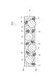
- FIG. 1 is a cross-sectional view showing an embodiment of an adhesive film.
- the adhesive film 1A (1) according to the embodiment includes a first adhesive layer 10.
- the first adhesive layer 10 contains a first adhesive component 11 and a first conductive particle 12 and a second conductive particle 13 dispersed in the first adhesive component 11.
- the first adhesive component 11 is composed of, for example, a material that is curable by heat or light, and is an epoxy adhesive, a radically curable adhesive, a thermoplastic adhesive containing polyurethane, a polyvinyl ester, or the like. It may be.
- the first adhesive component 11 may be made of a crosslinkable material because it is excellent in heat resistance and moisture resistance after adhesion.
- the epoxy adhesive contains an epoxy resin, which is a thermosetting resin, as a main component. Epoxy-based adhesives are preferably used because they can be cured in a short time, have good connection workability, and have excellent adhesiveness.
- the radical-curable adhesive has characteristics such as being superior in curability at a low temperature for a short time as compared with an epoxy-based adhesive, and is therefore appropriately used depending on the intended use.
- the epoxy adhesive contains, for example, an epoxy resin (thermosetting material) and a curing agent, and may further contain a thermoplastic resin, a coupling agent, a filler, and the like, if necessary.
- the epoxy resin examples include bisphenol A type epoxy resin, bisphenol F type epoxy resin, bisphenol S type epoxy resin, phenol novolac type epoxy resin, cresol novolac type epoxy resin, bisphenol A novolac type epoxy resin, and bisphenol F novolac type epoxy resin. , Alicyclic epoxy resin, glycidyl ester type epoxy resin, glycidylamine type epoxy resin, hydrantin type epoxy resin, isocyanurate type epoxy resin, aliphatic chain epoxy resin and the like. These epoxy resins may be halogenated, hydrogenated, or have a structure in which an acryloyl group or a methacryloyl group is added to the side chain. These epoxy resins are used alone or in combination of two or more.
- the curing agent is not particularly limited as long as it can cure the epoxy resin.
- an anionic polymerizable catalytic curing agent, a cationically polymerizable catalytic curing agent, a heavy addition type curing agent and the like can be used. Can be mentioned. Of these, an anionic or cationically polymerizable catalytic curing agent is preferable because it is excellent in quick curing property and does not require consideration of chemical equivalents.
- anionic or cationically polymerizable catalytic curing agents include imidazole, hydrazide, boron trifluoride-amine complex, onium salt (aromatic sulfonium salt, aromatic diazonium salt, aliphatic sulfonium salt, etc.), amineimide, and diamino. Examples thereof include maleonitrile, melamine and its derivatives, salts of polyamines, dicyandiamide and the like, and modified products thereof can also be used. Examples of the heavy addition type curing agent include polyamines, polymercaptans, polyphenols, acid anhydrides and the like.
- curing agents may be microencapsulated latent curing agents coated with a polymer substance such as polyurethane or polyester, a metal thin film such as nickel or copper, or an inorganic substance such as calcium silicate. .. Latent hardeners are preferred because they can extend the pot life.
- the curing agent may be used alone or in combination of two or more.
- the content of the curing agent may be 0.05 to 20 parts by mass with respect to 100 parts by mass of the total amount of the thermosetting material and the thermoplastic resin to be blended if necessary.
- the radical-curable adhesive contains, for example, a radical-polymerizable material and a radical polymerization initiator (also called a curing agent), and further contains a thermoplastic resin, a coupling agent, a filler, and the like, if necessary. It's okay.
- any substance having a functional group that is polymerized by radicals can be used without particular limitation.
- a radically polymerizable material such as an acrylate (including the corresponding methacrylate; the same applies hereinafter) compound, an acryloxy (including the corresponding metaacryloxy; the same applies hereinafter) compound, a maleimide compound, a citraconimide resin, and a nadiimide resin.
- radically polymerizable materials may be in the state of a monomer or an oligomer, or may be in the state of a mixture of a monomer and an oligomer.
- acrylate compound examples include methyl acrylate, ethyl acrylate, isopropyl acrylate, isobutyl acrylate, ethylene glycol diacrylate, diethylene glycol diacrylate, trimethyl propantriacrylate, tetramethylol methanetetraacrylate, 2-hydroxy-1,3-diacrylate.
- a radically polymerizable material such as an acrylate compound may be used together with a polymerization inhibitor such as hydroquinone or methyl ether hydroquinone, if necessary.
- the radically polymerizable material such as an acrylate compound preferably has at least one substituent such as a dicyclopentenyl group, a tricyclodecanyl group, or a triazine ring from the viewpoint of improving heat resistance.
- the radically polymerizable material other than the acrylate compound for example, the compound described in International Publication No. 2009/0638227 can be preferably used.
- the radically polymerizable material may be used alone or in combination of two or more.
- radical polymerization initiator for example, any compound that decomposes by heating or irradiation with light to generate free radicals can be used without particular limitation.
- Specific examples thereof include peroxide compounds and azo compounds. These compounds are appropriately selected according to the target connection temperature, connection time, pot life, and the like.
- radical polymerization initiator examples include diacyl peroxide, peroxydicarbonate, peroxyester, peroxyketal, dialkyl peroxide, hydroperoxide, silyl peroxide and the like.
- peroxyesters, dialkyl peroxides, hydroperoxides, silyl peroxides and the like are preferable, and peroxyesters capable of obtaining high reactivity are more preferable.
- the radical polymerization initiators for example, the compounds described in International Publication No. 2009/0638227 can be preferably used.
- the radical polymerization initiator may be used alone or in combination of two or more.
- the content of the radical polymerization initiator may be 0.1 parts by mass or more and 10 parts by mass or less with respect to 100 parts by mass of the total amount of the radically polymerizable material and the thermoplastic resin to be blended if necessary. It's okay.
- thermoplastic resin blended as necessary in the epoxy adhesive and the radical curable adhesive makes it easy to form the adhesive into a film, for example.
- thermoplastic resin examples include phenoxy resin, polyvinyl formal resin, polystyrene resin, polyvinyl butyral resin, polyester resin, polyamide resin, xylene resin, polyurethane resin, polyester urethane resin, phenol resin, terpene phenol resin and the like.
- the thermoplastic resin for example, the compound described in International Publication No. 2009/0638227 can be preferably used.
- phenoxy resin is preferable because it is excellent in adhesiveness, compatibility, heat resistance, mechanical strength and the like.
- the thermoplastic resin is used alone or in combination of two or more.
- the content of the thermoplastic resin When blended in an epoxy adhesive, the content of the thermoplastic resin may be 5 parts by mass or more and 80 parts by mass or less with respect to 100 parts by mass of the total amount of the thermoplastic resin and the thermosetting material. It's okay.
- the content of the thermoplastic resin When blended in a radical curable adhesive, the content of the thermoplastic resin may be 5 parts by mass or more and 80 parts by mass or less with respect to 100 parts by mass of the total amount of the thermoplastic resin and the radically polymerizable material. May be.
- the first adhesive component 11 is a thermal radical curable adhesive containing a thermoplastic resin, a radically polymerizable material liquid at 30 ° C., and a radical polymerization initiator.
- the thermal radical curable adhesive has a lower viscosity than the above-mentioned adhesive.
- the content of the radically polymerizable material in the thermally radical curable adhesive is 20 parts by mass or more, 30 parts by mass or more, or 40 parts by mass or more with respect to 100 parts by mass of the total amount of the thermoplastic resin and the radically polymerizable material. It may be 80 parts by mass or less.
- the first adhesive component 11 may be an epoxy-based adhesive containing a thermoplastic resin, a thermosetting material containing an epoxy resin liquid at 30 ° C., and a curing agent.
- the content of the epoxy resin in the epoxy adhesive is 20 parts by mass or more, 30 parts by mass or more, or 40 parts by mass or more with respect to 100 parts by mass of the total amount of the thermoplastic resin and the thermosetting material. It may be 80 parts by mass or less.
- the volume ratio of the first adhesive component 11 to the first adhesive layer 10 may be, for example, 55% by volume or more or 65% by volume or more based on the total volume of the first adhesive layer 10. It may be 95% by volume or less or 85% by volume or less.
- the first conductive particle 12 has a dendrite-like shape (also called a dendritic shape), and includes one main shaft and a plurality of branches that branch two-dimensionally or three-dimensionally from the main shaft.
- the first conductive particles 12 may be formed of a metal such as copper or silver, and may be, for example, silver-coated copper particles in which the copper particles are coated with silver.
- the first conductive particles 12 may be known, and specifically, for example, ACBY-2 (Mitsui Mining & Smelting Co., Ltd.), CE-1110 (Fukuda Metal Foil Powder Industry Co., Ltd.), #FSP (JX). Metal Co., Ltd.), # 51-R (JX Nippon Mining & Metal Co., Ltd.), etc.
- the first conductive particle 12 can be produced by a known method (for example, the method described in International Publication No. 2014/021037).
- the content of the first conductive particles 12 in the first adhesive layer 10 is based on the total volume of the first adhesive layer 10. From the viewpoint of further reducing the resistance of the connector, it is preferably 10% by volume or more, more preferably 20% by volume or more, still more preferably 30% by volume or more, and from the viewpoint of improving the adhesive strength of the adhesive film. It is preferably 60% by volume or less, more preferably 55% by volume or less, still more preferably 50% by volume or less.
- the second conductive particle 13 may have, for example, a non-conductive nuclei and a conductive layer provided on the nuclei.
- the core is made of a non-conductive material such as glass, ceramic, or resin, and is preferably made of resin.
- the resin include acrylic resin, styrene resin, silicone resin, polybutadiene resin, and copolymers of monomers constituting these resins.
- the average particle size of the nuclei is appropriately selected so that the average particle size of the second conductive particles 13 is in the range described later.
- the conductive layer is formed of, for example, gold, silver, copper, nickel, palladium or an alloy thereof. From the viewpoint of excellent conductivity, the conductive layer preferably contains at least one selected from gold, nickel and palladium, more preferably gold or palladium, and even more preferably gold.
- the conductive layer is formed, for example, by plating the core with the metal.
- the thickness of the conductive layer may be, for example, 10 nm or more and 400 nm or less.
- the average particle size of the second conductive particles 13 may be, for example, 10 ⁇ m or more, 20 ⁇ m or more, or 30 ⁇ m or more, and may be 50 ⁇ m or less, 45 ⁇ m or less, or 40 ⁇ m or less.
- the average particle size of the second conductive particle 13 and the nuclei constituting the second conductive particle 13 is measured by a particle size distribution measuring device (Microtrack (product name, Nikkiso Co., Ltd.)) using a laser diffraction / scattering method.
- the content of the second conductive particles 13 in the first adhesive layer 10 is based on the total volume of the first adhesive layer 10. It may be 2% by volume or more or 5% by volume or more, and may be 20% by volume or less or 10% by volume or less.
- the thickness of the first adhesive layer 10 may be, for example, 10 ⁇ m or more, 20 ⁇ m or more, or 30 ⁇ m or more, and may be 50 ⁇ m or less, 45 ⁇ m or less, or 40 ⁇ m or less.
- the thickness of the first adhesive layer 10 is the first in the one surface 10a of the first adhesive layer 10 where the first conductive particles 12 and the second conductive particles 13 do not protrude. It is defined as the thickness of the adhesive layer 10.
- the adhesive film 1A As shown in FIG. 1, a part of the plurality of first conductive particles 12 and the second conductive particles 13 contained in the first adhesive layer 10 (first adhesive).
- the first conductive particles 12 and the second conductive particles 13) existing in the vicinity of the one surface 10a of the layer 10 are arranged so as to protrude from the one surface 10a of the first adhesive layer 10.
- the first adhesive layer 10 supports, for example, a mixed solution containing the first conductive particles 12, the second conductive particles 13, and the first adhesive component 11 dissolved in a solvent.
- the first conductive particles 12 and the second conductive particles 13 are formed in the first adhesive layer 10 as the boiling point of the solvent used at this time is lower.
- it becomes easy to protrude from the surface 10a the higher the drying condition for removing the solvent and the shorter the time, the easier it is for the first conductive particles 12 and the second conductive particles 13 to protrude from one surface 10a of the first adhesive layer 10.
- both the first conductive particles 12 and the second conductive particles 13 are arranged so as to protrude from one surface 10a of the first adhesive layer 10, but the first adhesive layer.
- a part of the plurality of conductive particles contained in 10 may be arranged so as to protrude from one surface 10a of the first adhesive layer 10.
- only the first conductive particles 12 need to be arranged so as to protrude from one surface 10a of the first adhesive layer 10. It may be arranged so as to project from one surface 10a of the layer 10, or only the second conductive particles 13 may be arranged so as to project from one surface 10a of the first adhesive layer 10.
- the adhesive film 1A includes only one layer of the first adhesive layer 10, but in another embodiment, the adhesive film 1 may include two or more layers.
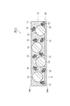
- FIG. 2 is a cross-sectional view showing another embodiment of the adhesive film 1. As shown in FIG. 2, the adhesive film 1B (1) according to another embodiment is provided on one surface 10a of the first adhesive layer 10 in addition to the above-mentioned first adhesive layer 10. The second adhesive layer 20 may be further provided.
- the second adhesive layer 20 contains, for example, the second adhesive component 21.
- the second adhesive layer 20 does not have to contain conductive particles.
- the second adhesive component 21 may be composed of a material selected from the materials exemplified as the first adhesive component 11, but is different from the first adhesive component (having a different composition). ..
- the second adhesive layer 20 (second adhesive component 21) is preferably the first adhesive layer 10 (second adhesive layer 10) from the viewpoint of excellent adhesiveness when the adhesive film 1B is attached to the object to be adhered. It has an adhesive strength higher than the adhesive strength of the adhesive component 11) of 1.
- the melt viscosity of the second adhesive layer 20 at 25 ° C. is preferably lower than the melt viscosity of the first adhesive layer 10 at 25 ° C.
- the melt viscosity of the first adhesive layer 10 at 25 ° C. may be, for example, 1 ⁇ 10 4 Pa ⁇ s or more, 5 ⁇ 10 4 Pa ⁇ s or more, or 1 ⁇ 10 5 Pa ⁇ s or more.
- the melt viscosity of the second adhesive layer 20 at 25 ° C. may be less than 1 ⁇ 10 4 Pa ⁇ s, 7 ⁇ 10 4 Pa ⁇ s or less, or 5 ⁇ 10 5 Pa ⁇ s or less.
- the melt viscosity of each adhesive layer is measured by laminating each adhesive layer so as to have a thickness of 500 ⁇ m, and the measurement sample is cut into 10 mm ⁇ 10 mm (thickness 500 ⁇ m) and film melt viscosity measuring device (for example, 500 ⁇ m). It is measured using a product name: ARES-G2, manufactured by TA Instruments Co., Ltd., under the conditions of measurement frequency: 10 Hz and heating rate: 10 ° C./min.
- the thickness of the second adhesive layer 20 is preferably thinner than the thickness of the first adhesive layer 10 from the viewpoint of more preferably obtaining the effect of blocking resistance.
- the thickness of the second adhesive layer 20 may be, for example, 0.5 ⁇ m or more, 1 ⁇ m or more, 1.5 ⁇ m or more, or 2 ⁇ m or more, preferably 5 ⁇ m or less, more preferably 4 ⁇ m or less, still more preferably 3 ⁇ m. It is as follows.
- the thickness of the second adhesive layer 20 is the second thickness of the one surface 10a of the first adhesive layer 10 where the first conductive particles 12 and the second conductive particles 13 do not protrude. It is defined as the thickness of the adhesive layer 20.
- the adhesive film 1B is provided with the second adhesive layer 20, so that excellent blocking resistance can be obtained when used in the form of a reel body (details are as follows). Will be described later).
- both the first conductive particles 12 and the second conductive particles 13 are moved from the interface S between the first adhesive layer 10 and the second adhesive layer 20 to the second adhesive layer 20 side.
- a part of the plurality of conductive particles contained in the first adhesive layer 10 is second from the interface S between the first adhesive layer 10 and the second adhesive layer 20. It suffices to be arranged so as to project toward the adhesive layer 20 side.
- only the first conductive particles 12 are secondly bonded from the interface S between the first adhesive layer 10 and the second adhesive layer 20. It may be arranged so as to project toward the agent layer 20, and only the second conductive particles 13 are arranged from the interface S between the first adhesive layer 10 and the second adhesive layer 20 to the second adhesive layer 20. It may be arranged so as to protrude to the side.
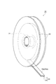
- FIG. 3 is a perspective view showing an embodiment of the reel body.
- the reel body 30 according to the embodiment is formed on a tubular winding core 31, a disk-shaped side plate 32 provided on both end surfaces of the winding core 31 in the axial direction, and a winding core 31. It is provided with a long adhesive tape 33 that has been wound into a heavy body.
- the adhesive tape 33 includes a long support 34 and an adhesive film 1.
- the adhesive film 1 has a long shape substantially the same as that of the support 34.
- the length of the support 34 may be, for example, 1 to 400 m.
- the thickness of the support 34 may be, for example, 4 to 200 ⁇ m.
- the width of the support 34 may be, for example, 0.5 to 30 mm.
- the support 34 includes, for example, polyethylene terephthalate, polyethylene naphthalate, polyethylene isophthalate, polybutylene terephthalate, polyolefin, polyacetate, polycarbonate, polyphenylene sulfide, polyamide, ethylene / vinyl acetate copolymer, polyvinyl chloride, polyvinylidene chloride, and the like. It may be made of a polymer such as a synthetic rubber type or a liquid crystal polymer.
- the other surface of the first adhesive layer 10 (the surface opposite to the surface on which the first conductive particles 12 and the second conductive particles 13 protrude) is the support 34. It is provided on the support 34 so as to face the side.
- the adhesive film 1A is one surface of the first adhesive layer 10 (first conductive particles 12 and second conductive particles).
- a surface on which 13 protrudes) 10a is provided on the support 34 so as to face the side opposite to the support 34.
- the adhesive film 1 is the adhesive film 1B shown in FIG. 2
- the surface 20a of the second adhesive layer 20 opposite to the first adhesive layer 10 is the support 34. Is provided on the support 34 so as to face the opposite side.
- the adhesive tape in the reel body 30 is one surface of the first adhesive layer 10 (first conductive particles 12 and second conductive particles).
- the surface on which 13 protrudes) 10a is in contact with the back surface (the surface opposite to the surface on which the first adhesive layer 10 is provided) of the support 34 in the adhesive tape wound inside one roll. It is rolled up. At this time, since the first conductive particles 12 and the second conductive particles 13 protrude on the one side 10a side of the first adhesive layer 10, the first adhesive component 11 is wound one roll inward.
- the protruding first conductive particles 12 and the second conductive particles 13 are one surface 10a of the first adhesive layer 10 and the support. It acts like a spacer between the back surface 34a of the 34 and the distance between the two is easily maintained). Therefore, in the reel body 30 including the adhesive film 1A, even if the adhesive strength of the adhesive film 1 (first adhesive component 11) is the same, excellent blocking resistance (particularly, winding inside one roll). Blocking resistance of the support 34 to the back surface 34a of the adhesive tape 33A) is obtained. Such an effect can be similarly exhibited even when the adhesive force of the adhesive film 1 (first adhesive component 11) is increased.
- the adhesive film 1 is the adhesive film 1B shown in FIG. 2, the reason is not clear, but the excellent blocking resistance as described above can be obtained.
- the adhesive film 1A is provided with the second adhesive layer 20, so that the adhesive film 1A has better adhesiveness than the adhesive film 1A. Be done.
- the adhesive film 1 and the adhesive tape 33 described above are suitably used as an adhesive for electrically connecting electronic members to each other.
- the type of electronic member is not particularly limited.
- the electronic member includes, for example, a substrate and an electrode 9 formed on one surface of the substrate.
- the substrate may be, for example, a substrate made of glass, ceramic, polyimide, polycarbonate, polyester, polyether sulfone, or the like.
- the electrode may be, for example, an electrode formed of gold, silver, copper, tin, aluminum, ruthenium, rhodium, palladium, osmium, iridium, platinum, indium tin oxide (ITO) or the like.
- dendrite-like conductive particle As the first conductive particle, dendrite-like conductive particle (silver-coated copper particle, product name: ACBY-2, manufactured by Mitsui Mining & Smelting Co., Ltd.) was used.
- the second conductive particle was prepared by the following procedure. First, benzoyl peroxide was added as a polymerization initiator to a mixed solution of divinylbenzene, styrene monomer, and butyl methacrylate, and heated with uniform stirring at high speed to carry out a polymerization reaction to obtain a fine particle dispersion. The fine particle dispersion was filtered and dried under reduced pressure to obtain a block which is an aggregate of fine particles. Further, by pulverizing this block body, a nuclei having an average particle size of 20 ⁇ m was prepared.
- a palladium catalyst (manufactured by Muromachi Technos Co., Ltd., product name: MK-2605) is supported on the surface of the above nucleus and activated with an accelerator (manufactured by Muromachi Technos Co., Ltd., product name: MK-370).
- the nuclei were put into a mixed solution of a nickel sulfate aqueous solution, a sodium hypophosphite aqueous solution and a sodium tartrate aqueous solution heated to 60 ° C., and an electroless plating pre-step was performed. The mixture was stirred for 20 minutes and it was confirmed that hydrogen foaming stopped.
- a mixed solution was obtained by dispersing 45 parts by volume of the first conductive particles and 15 parts by volume of the second conductive particles with respect to 100 parts by volume of the adhesive component.
- the obtained mixed solution was applied onto a fluororesin film (support) having a thickness of 80 ⁇ m, and the solvent was removed by hot air drying at 70 ° C. for 10 minutes to form a fluororesin film having a thickness of 25 ⁇ m.
- An adhesive film (adhesive tape) having a first adhesive layer was obtained.
- Example 1 An adhesive film was obtained in the same manner as in Comparative Example 1 except that the drying conditions for removing the solvent from the mixed solution coated on the fluororesin film were changed to hot air drying at 90 ° C. for 2 minutes.
- Example 2 When obtaining the mixed solution, 45 parts by volume of the first conductive particles and 15 parts by volume of the second conductive particles were dispersed in 100 parts by volume of the adhesive component, and 30 parts by volume of acetone (boiling point 56. An adhesive film was obtained in the same manner as in Comparative Example 1 except that 1 ° C.) was further added.
- Adhesive tapes (length: 100 m) of Examples 1 and 2 and Comparative Example 1 in which a 3-inch ABS core (manufactured by Showa Maru Cylinder Co., Ltd.) was used as a winding core and cut to a width of 5 mm with respect to the winding core. Wrapped around. Subsequently, disc-shaped polystyrene side plates (diameter: 180 mm, thickness: 1 mm) were fitted to both ends of the winding core to prepare a reel body.
- a 3-inch ABS core manufactured by Showa Maru Cylinder Co., Ltd.
- a SUS plate was placed in a constant temperature bath (manufactured by AS ONE Corporation, product name: small incubator IC-150MA) set at 30 ° C., and the produced reel body was placed horizontally on the SUS plate (reel body). The side plate and the SUS plate were parallel to each other) and allowed to stand for 72 hours.
- the blocking resistance after the horizontal placement test was evaluated according to the following criteria according to the state when the adhesive tape was to be pulled out from the reel body (winding core) at 25 ° C. after standing. The results are shown in Table 1.
- B Although the adhesive film was partially peeled off from the support, the adhesive tape could be pulled out.
- C The adhesive tape could not be pulled out.
- connection resistance of each of the adhesive films of Examples 1 and 2 and Comparative Example 1 was evaluated by the following procedure. The results are shown in Table 1.
- FIG. 4A is a top view of the resistance measurement sample 40
- FIG. 4B is a cross-sectional view taken along the line IVb-IVb of FIG. 4A.
- a polyimide film 42 (size: 30 mm ⁇ 30 mm, thickness: 25 ⁇ m) was placed on a copper foil 41 (size: 35 mm ⁇ 35 mm, thickness: 25 ⁇ m).
- the aluminum foil 44 (size: 15 mm ⁇ 20 mm, thickness) is passed through each of the adhesive films 43 (size: 15 mm ⁇ 3 mm) of Examples 1 and 2 and Comparative Example 1. : 25 ⁇ m) was connected.
- the current and voltage between the copper foil 41 and the aluminum foil 44 were measured with an ammeter A and a voltmeter V, respectively, and the resistance value (initial) was calculated.
- the resistance measurement sample 40 prepared as described above is held at ⁇ 20 ° C. for 30 minutes using TSA-43EL manufactured by ESPEC, heated to 100 ° C. over 10 minutes, and held at 100 ° C. for 30 minutes. The temperature was lowered to ⁇ 20 ° C. over 10 minutes, which was subjected to a cycle test in which 250 cycles of heat cycles were repeated. The resistance value (after the cycle test) was measured for each of the resistance measurement samples 40 after the cycle test in the same manner as described above.
- the adhesiveness was evaluated according to the following criteria according to the state of the adhesive film when the support was attempted to be peeled off from the adhesive film.
- Example 3 An adhesive film was obtained in the same manner as in Comparative Example 2 except that the drying conditions for removing the solvent from the mixed solution coated on the fluororesin film were changed to hot air drying at 90 ° C. for 2 minutes.
- Example 5 A second adhesive layer was provided on the surface of the first adhesive layer obtained in Example 2 on the opposite side of the fluororesin film in the same manner as in Example 4.
- Example 3 When the appearance of each of the adhesive films (adhesive tapes) of Examples 3 to 5 and Comparative Example 2 was observed in the same manner as described above, in Example 3, the first conductive particles and the second conductive particles were observed. It was confirmed that the particles protruded from the first adhesive layer, whereas in Comparative Example 2, the first conductive particles and the second conductive particles protruded from the first adhesive layer. Not confirmed. Further, in Examples 4 and 5, the surface of the second adhesive layer has an uneven shape that is considered to be derived from the first conductive particles and the second conductive particles protruding from the first adhesive layer. It was confirmed that there was.
- the adhesive strength, the blocking resistance, and the connection resistance were evaluated in the same manner as described above. Further, with respect to each of the adhesive films of Examples 3 to 5, the adhesiveness was evaluated in the same manner as described above. However, the adhesive films of Examples 3 to 5 and Comparative Example 2 are more likely to cause a blocking phenomenon due to their higher adhesive strength than the adhesive films of Examples 1 and 2 and Comparative Example 1. Therefore, in the evaluation of blocking resistance, the time for allowing the reel body to stand in the constant temperature bath was changed from 72 hours to 24 hours.
- Adhesive film 10 ... First adhesive layer, 10a ... One side of the first adhesive layer, 11 ... First adhesive component, 12 ... First conductive particles, 13 ... Second conductive particles, 20 ... second adhesive layer, 30 ... reel body, 31 ... core, 33 ... adhesive tape, 34 ... support.
Abstract
Description
上述した特許文献1の実施例に従って、以下の手順で接着剤フィルムを作製した。
まず、フェノキシ樹脂(ユニオンカーバイド株式会社製、製品名:PKHC、重量平均分子量:45000)50gを、トルエン(沸点:110.6℃)と酢酸エチル(沸点:77.1℃)との混合溶剤(質量比でトルエン:酢酸エチル=1:1)に溶解して、固形分40質量%のフェノキシ樹脂溶液を得た。このフェノキシ樹脂溶液に、ラジカル重合性物質として、ウレタンアクリレート(根上工業株式会社製、製品名:UN7700)及びリン酸エステルジメタクリレート(共栄社化学株式会社製、製品名:ライトエステルP-2M)と、硬化剤として1,1-ビス(t-ヘキシルパーオキシ)-3,3,5-トリメチルシクロヘキサン(日本油脂株式会社製、製品名:パーヘキサTMH)とを、フェノキシ樹脂:ウレタンアクリレート:リン酸エステルジメタクリレート:硬化剤=10:10:3:2の固形質量比で配合し接着剤溶液を得た。 (Comparative Example 1)
An adhesive film was produced by the following procedure according to the above-mentioned example of
First, 50 g of phenoxy resin (manufactured by Union Carbide Co., Ltd., product name: PKHC, weight average molecular weight: 45,000) is mixed with toluene (boiling point: 110.6 ° C.) and ethyl acetate (boiling point: 77.1 ° C.) ( It was dissolved in toluene: ethyl acetate = 1: 1) by mass ratio to obtain a phenoxy resin solution having a solid content of 40% by mass. Urethane acrylate (manufactured by Negami Kogyo Co., Ltd., product name: UN7700) and phosphate ester dimethacrylate (manufactured by Kyoeisha Chemical Co., Ltd., product name: light ester P-2M) were added to this phenoxy resin solution as radically polymerizable substances. As a curing agent, 1,1-bis (t-hexyl peroxy) -3,3,5-trimethylcyclohexane (manufactured by Nippon Oil & Fats Co., Ltd., product name: PerhexaTMH) is used, and phenoxy resin: urethane acrylate: phosphate ester di. Ester: Hardener = 10:10: 3: 2 was blended in a solid mass ratio to obtain an adhesive solution.
まず、ジビニルベンゼン、スチレンモノマー及びブチルメタクリレートの混合溶液に、重合開始剤としてベンゾイルパーオキサイドを投入して、高速で均一撹拌しながら加熱して重合反応を行うことで微粒子分散液を得た。この微粒子分散液をろ過し減圧乾燥することで、微粒子の凝集体であるブロック体を得た。さらに、このブロック体を粉砕することで、平均粒子径20μmの核体を作製した。 The second conductive particle was prepared by the following procedure.
First, benzoyl peroxide was added as a polymerization initiator to a mixed solution of divinylbenzene, styrene monomer, and butyl methacrylate, and heated with uniform stirring at high speed to carry out a polymerization reaction to obtain a fine particle dispersion. The fine particle dispersion was filtered and dried under reduced pressure to obtain a block which is an aggregate of fine particles. Further, by pulverizing this block body, a nuclei having an average particle size of 20 μm was prepared.
フッ素樹脂フィルム上に塗布された混合溶液から溶剤を除去する際の乾燥条件を、90℃で2分間の熱風乾燥に変更した以外は、比較例1と同様にして接着剤フィルムを得た。 (Example 1)
An adhesive film was obtained in the same manner as in Comparative Example 1 except that the drying conditions for removing the solvent from the mixed solution coated on the fluororesin film were changed to hot air drying at 90 ° C. for 2 minutes.
混合溶液を得る際に、100体積部の接着剤成分に対して、45体積部の第1の導電粒子及び15体積部の第2の導電粒子を分散させ、30体積部のアセトン(沸点56.1℃)を更に加えた以外は、比較例1と同様にして接着剤フィルムを得た。 (Example 2)
When obtaining the mixed solution, 45 parts by volume of the first conductive particles and 15 parts by volume of the second conductive particles were dispersed in 100 parts by volume of the adhesive component, and 30 parts by volume of acetone (boiling point 56. An adhesive film was obtained in the same manner as in Comparative Example 1 except that 1 ° C.) was further added.
実施例1,2及び比較例1の各接着剤フィルムについて、フッ素樹脂フィルムと反対側の接着剤フィルムの表面をレーザー顕微鏡(オリンパス株式会社製、製品名:OLS40-SU)により観察したところ、実施例1,2では、第1の導電粒子及び第2の導電粒子が第1の接着剤層から突出していることが確認されたのに対し、比較例1では、第1の導電粒子及び第2の導電粒子が第1の接着剤層から突出していることは確認されなかった。 [Observation of appearance]
For each of the adhesive films of Examples 1 and 2 and Comparative Example 1, the surface of the adhesive film on the opposite side to the fluororesin film was observed with a laser microscope (manufactured by Olympus Co., Ltd., product name: OLS40-SU). In Examples 1 and 2, it was confirmed that the first conductive particles and the second conductive particles protruded from the first adhesive layer, whereas in Comparative Example 1, the first conductive particles and the second conductive particles were confirmed. It was not confirmed that the conductive particles of the above were protruding from the first adhesive layer.
銅箔(大きさ:40mm×15mm、厚さ:25μm)の上に、実施例1,2及び比較例1の各接着剤フィルム(大きさ:15mm×3mm)を介して、アルミ箔(大きさ:15mm×20mm、厚さ:25μm)を接着させた。東洋ボールドウィン株式会社製テンシロンUTM-4を用い、JIS Z0237に準じて、剥離速度50mm/分、25℃の条件にて90度剥離法で銅箔とアルミ箔との接着強度を測定した。結果を表1に示す。 [Evaluation of adhesive strength]
An aluminum foil (size) is placed on a copper foil (size: 40 mm × 15 mm, thickness: 25 μm) via the adhesive films (size: 15 mm × 3 mm) of Examples 1 and 2 and Comparative Example 1. : 15 mm × 20 mm, thickness: 25 μm) were adhered. Using Tencilon UTM-4 manufactured by Toyo Baldwin Co., Ltd., the adhesive strength between the copper foil and the aluminum foil was measured by the 90 degree peeling method under the conditions of a peeling speed of 50 mm / min and 25 ° C. according to JIS Z0237. The results are shown in Table 1.
3インチABSコア(株式会社昭和丸筒製)を巻芯として用い、当該巻芯に対して、5mm幅に切断した実施例1,2及び比較例1の各接着剤テープ(長さ:100m)を巻き付けた。続いて、巻芯の両端に、円盤状のポリスチレン製の側板(直径:180mm、厚み:1mm)を嵌め込み、リール体を作製した。 [Evaluation of blocking resistance]
Adhesive tapes (length: 100 m) of Examples 1 and 2 and Comparative Example 1 in which a 3-inch ABS core (manufactured by Showa Maru Cylinder Co., Ltd.) was used as a winding core and cut to a width of 5 mm with respect to the winding core. Wrapped around. Subsequently, disc-shaped polystyrene side plates (diameter: 180 mm, thickness: 1 mm) were fitted to both ends of the winding core to prepare a reel body.
A:支持体から接着剤フィルムが剥がれずに、接着剤テープを引き出すことができた。
B:支持体から接着剤フィルムが一部剥がれるものの、接着剤テープを引き出すことができた。
C:接着剤テープを引き出すことができなかった。 Subsequently, a SUS plate was placed in a constant temperature bath (manufactured by AS ONE Corporation, product name: small incubator IC-150MA) set at 30 ° C., and the produced reel body was placed horizontally on the SUS plate (reel body). The side plate and the SUS plate were parallel to each other) and allowed to stand for 72 hours. The blocking resistance after the horizontal placement test was evaluated according to the following criteria according to the state when the adhesive tape was to be pulled out from the reel body (winding core) at 25 ° C. after standing. The results are shown in Table 1.
A: The adhesive tape could be pulled out without peeling the adhesive film from the support.
B: Although the adhesive film was partially peeled off from the support, the adhesive tape could be pulled out.
C: The adhesive tape could not be pulled out.
実施例1,2及び比較例1の各接着剤フィルムについて、以下の手順で接続抵抗を評価した。結果を表1に示す。 [Evaluation of connection resistance]
The connection resistance of each of the adhesive films of Examples 1 and 2 and Comparative Example 1 was evaluated by the following procedure. The results are shown in Table 1.
実施例1,2の接着剤フィルムについては、以下の手順で貼り付け性も評価した。結果を表1に示す。
銅箔(大きさ:35mm×35mm、厚さ:25μm)の上に、3mm×3mmの大きさで支持体ごと切り取った各接着剤フィルム(接着剤テープ)を貼り付けた。ここで、接着剤フィルムを貼り付ける際の加熱加圧は、接着剤フィルム上にテフロン(登録商標)製のシート(大きさ:15mm×40mm、厚さ:50μm)を載せた状態で実施した。また、加熱加圧は、条件1:70℃1MPa 2秒間、及び、条件2:50℃ 1MPa 1秒間の二つの条件でそれぞれ実施した。支持体を接着剤フィルムから剥がそうとした際の接着剤フィルムの状態によって、以下の基準で貼り付け性を評価した。
A:接着剤フィルムが浮かなかった。
B:接着剤フィルムがわずかに浮いた。
C:接着剤フィルムが大きく浮き、しわが発生した。
D:接着剤フィルムが支持体から剥がれなかった。 [Evaluation of stickability]
For the adhesive films of Examples 1 and 2, the adhesiveness was also evaluated by the following procedure. The results are shown in Table 1.
On the copper foil (size: 35 mm × 35 mm, thickness: 25 μm), each adhesive film (adhesive tape) cut out together with the support in a size of 3 mm × 3 mm was attached. Here, the heating and pressurizing when the adhesive film was attached was carried out with a Teflon (registered trademark) sheet (size: 15 mm × 40 mm, thickness: 50 μm) placed on the adhesive film. The heating and pressurization was carried out under two conditions: condition 1: 70 ° C. for 1 MPa for 2 seconds and condition 2: 50 ° C. for 1 MPa for 1 second. The adhesiveness was evaluated according to the following criteria according to the state of the adhesive film when the support was attempted to be peeled off from the adhesive film.
A: The adhesive film did not float.
B: The adhesive film floated slightly.
C: The adhesive film floated greatly and wrinkles occurred.
D: The adhesive film did not peel off from the support.

接着剤溶液を得る際に、フェノキシ樹脂、ウレタンアクリレート、リン酸エステルジメタクリレート及び硬化剤の固形質量比を、フェノキシ樹脂:ウレタンアクリレート:リン酸エステルジメタクリレート:硬化剤=5:14:4:2に変更した以外は、比較例1と同様にして接着剤フィルムを得た。なお、このような変更により、比較例2の第1の接着剤層の接着力が、比較例1の第1の接着剤層の接着力より高くなった。 (Comparative Example 2)
When obtaining the adhesive solution, the solid mass ratio of the phenoxy resin, urethane acrylate, phosphate ester dimethacrylate and curing agent was determined, and the solid mass ratio of the phenoxy resin: urethane acrylate: phosphate ester dimethacrylate: curing agent = 5: 14: 4: 2. An adhesive film was obtained in the same manner as in Comparative Example 1 except that it was changed to. Due to such a change, the adhesive force of the first adhesive layer of Comparative Example 2 became higher than the adhesive force of the first adhesive layer of Comparative Example 1.
フッ素樹脂フィルム上に塗布された混合溶液から溶剤を除去する際の乾燥条件を、90℃で2分間の熱風乾燥に変更した以外は、比較例2と同様にして接着剤フィルムを得た。 (Example 3)
An adhesive film was obtained in the same manner as in Comparative Example 2 except that the drying conditions for removing the solvent from the mixed solution coated on the fluororesin film were changed to hot air drying at 90 ° C. for 2 minutes.
まず、比較例2と同様にして、フェノキシ樹脂:ウレタンアクリレート:リン酸エステルジメタクリレート:硬化剤=5:14:4:2の固形質量比で接着剤溶液を得た。得られた接着剤溶液を、実施例1で得られた第1の接着剤層のフッ素樹脂フィルムと反対側の面上に塗布し、70℃で10分間熱風乾燥することにより溶剤を除去して、厚み2μmの第2の接着剤層を第1の接着剤層上に設けた。 (Example 4)
First, in the same manner as in Comparative Example 2, an adhesive solution was obtained with a solid mass ratio of phenoxy resin: urethane acrylate: phosphoric acid ester dimethacrylate: curing agent = 5: 14: 4: 2. The obtained adhesive solution was applied onto the surface of the first adhesive layer obtained in Example 1 on the side opposite to the fluororesin film, and dried with hot air at 70 ° C. for 10 minutes to remove the solvent. A second adhesive layer having a thickness of 2 μm was provided on the first adhesive layer.
実施例2で得られた第1の接着剤層のフッ素樹脂フィルムと反対側の面上に、実施例4と同様にして第2の接着剤層を設けた。 (Example 5)
A second adhesive layer was provided on the surface of the first adhesive layer obtained in Example 2 on the opposite side of the fluororesin film in the same manner as in Example 4.

Claims (7)
- 第1の接着剤成分及び複数の導電粒子を含有する第1の接着剤層を備える接着剤フィルムであって、
前記複数の導電粒子は、
デンドライト状の導電粒子である第1の導電粒子と、
前記第1の導電粒子以外の導電粒子であって、非導電性の核体及び該核体上に設けられた導電層を有する導電粒子である第2の導電粒子と、
を含み、
前記複数の導電粒子の一部は、前記第1の接着剤層の一方面から突出するように配置されている、接着剤フィルム。 An adhesive film comprising a first adhesive layer containing a first adhesive component and a plurality of conductive particles.
The plurality of conductive particles are
The first conductive particles, which are dendrite-like conductive particles, and
A second conductive particle which is a conductive particle other than the first conductive particle and has a non-conductive nucleus and a conductive layer provided on the nucleus.
Including
An adhesive film in which some of the plurality of conductive particles are arranged so as to project from one surface of the first adhesive layer. - 前記第1の導電粒子が、前記第1の接着剤層の前記一方面から突出するように配置されている、請求項1に記載の接着剤フィルム。 The adhesive film according to claim 1, wherein the first conductive particles are arranged so as to protrude from the one surface of the first adhesive layer.
- 前記第2の導電粒子が、前記第1の接着剤層の前記一方面から突出するように配置されている、請求項1に記載の接着剤フィルム。 The adhesive film according to claim 1, wherein the second conductive particles are arranged so as to protrude from the one surface of the first adhesive layer.
- 前記第1の導電粒子及び前記第2の導電粒子が、前記第1の接着剤層の前記一方面から突出するように配置されている、請求項1に記載の接着剤フィルム。 The adhesive film according to claim 1, wherein the first conductive particles and the second conductive particles are arranged so as to protrude from the one surface of the first adhesive layer.
- 前記第1の接着剤層の前記一方面上に設けられ、前記第1の接着剤成分と異なる第2の接着剤成分を含有する第2の接着剤層を更に備える、請求項1~4のいずれか一項に記載の接着剤フィルム。 Claims 1 to 4, further comprising a second adhesive layer provided on the one surface of the first adhesive layer and containing a second adhesive component different from the first adhesive component. The adhesive film according to any one item.
- 前記第1の接着剤層の厚さが10μm以上であり、前記第2の接着剤層の厚さが5μm以下である、請求項5に記載の接着剤フィルム。 The adhesive film according to claim 5, wherein the thickness of the first adhesive layer is 10 μm or more, and the thickness of the second adhesive layer is 5 μm or less.
- 巻芯と、前記巻芯に巻かれた接着剤テープと、を備え、
前記接着剤テープは、支持体と、請求項1~6のいずれか一項に記載の接着剤フィルムと、を有し、
前記接着剤フィルムは、前記第1の接着剤層の他方面が前記支持体側を向くように前記支持体上に設けられている、リール体。 A winding core and an adhesive tape wound around the winding core are provided.
The adhesive tape has a support and an adhesive film according to any one of claims 1 to 6.
The adhesive film is a reel body provided on the support so that the other surface of the first adhesive layer faces the support side.
Priority Applications (4)
| Application Number | Priority Date | Filing Date | Title |
|---|---|---|---|
| CN202180017869.5A CN115210331A (en) | 2020-03-04 | 2021-03-03 | Adhesive film and reel |
| US17/905,415 US20230163489A1 (en) | 2020-03-04 | 2021-03-03 | Adhesive film and reel body |
| KR1020227032129A KR20220145856A (en) | 2020-03-04 | 2021-03-03 | Adhesive film, and reel body |
| JP2022504438A JPWO2021177375A1 (en) | 2020-03-04 | 2021-03-03 |
Applications Claiming Priority (2)
| Application Number | Priority Date | Filing Date | Title |
|---|---|---|---|
| JP2020037070 | 2020-03-04 | ||
| JP2020-037070 | 2020-03-04 |
Publications (1)
| Publication Number | Publication Date |
|---|---|
| WO2021177375A1 true WO2021177375A1 (en) | 2021-09-10 |
Family
ID=77613432
Family Applications (1)
| Application Number | Title | Priority Date | Filing Date |
|---|---|---|---|
| PCT/JP2021/008264 WO2021177375A1 (en) | 2020-03-04 | 2021-03-03 | Adhesive film and reel body |
Country Status (6)
| Country | Link |
|---|---|
| US (1) | US20230163489A1 (en) |
| JP (1) | JPWO2021177375A1 (en) |
| KR (1) | KR20220145856A (en) |
| CN (1) | CN115210331A (en) |
| TW (1) | TW202136446A (en) |
| WO (1) | WO2021177375A1 (en) |
Citations (3)
| Publication number | Priority date | Publication date | Assignee | Title |
|---|---|---|---|---|
| JP2012102278A (en) * | 2010-11-12 | 2012-05-31 | Sony Chemical & Information Device Corp | Reel object and manufacturing method therefor, method for planarizing adhesive film |
| JP2018137237A (en) * | 2012-08-24 | 2018-08-30 | デクセリアルズ株式会社 | Method of producing anisotropic conductive film and anisotropic conductive film |
| WO2019131904A1 (en) * | 2017-12-28 | 2019-07-04 | 日立化成株式会社 | Connection structure and method for producing same |
Family Cites Families (4)
| Publication number | Priority date | Publication date | Assignee | Title |
|---|---|---|---|---|
| CN102017816A (en) * | 2008-04-28 | 2011-04-13 | 日立化成工业株式会社 | Circuit connecting material, film-like adhesive, adhesive reel, and circuit connecting structural body |
| CN107207181B (en) * | 2015-02-27 | 2020-10-20 | 迪睿合株式会社 | Roll body, film connected body, film wound body, and method for producing film connected body |
| WO2018042701A1 (en) | 2016-08-30 | 2018-03-08 | 日立化成株式会社 | Adhesive composition |
| TW201840767A (en) * | 2017-02-17 | 2018-11-16 | 日商日立化成股份有限公司 | Adhesive film |
-
2021
- 2021-03-03 JP JP2022504438A patent/JPWO2021177375A1/ja active Pending
- 2021-03-03 US US17/905,415 patent/US20230163489A1/en active Pending
- 2021-03-03 WO PCT/JP2021/008264 patent/WO2021177375A1/en active Application Filing
- 2021-03-03 CN CN202180017869.5A patent/CN115210331A/en active Pending
- 2021-03-03 KR KR1020227032129A patent/KR20220145856A/en unknown
- 2021-03-04 TW TW110107694A patent/TW202136446A/en unknown
Patent Citations (3)
| Publication number | Priority date | Publication date | Assignee | Title |
|---|---|---|---|---|
| JP2012102278A (en) * | 2010-11-12 | 2012-05-31 | Sony Chemical & Information Device Corp | Reel object and manufacturing method therefor, method for planarizing adhesive film |
| JP2018137237A (en) * | 2012-08-24 | 2018-08-30 | デクセリアルズ株式会社 | Method of producing anisotropic conductive film and anisotropic conductive film |
| WO2019131904A1 (en) * | 2017-12-28 | 2019-07-04 | 日立化成株式会社 | Connection structure and method for producing same |
Also Published As
| Publication number | Publication date |
|---|---|
| CN115210331A (en) | 2022-10-18 |
| US20230163489A1 (en) | 2023-05-25 |
| JPWO2021177375A1 (en) | 2021-09-10 |
| KR20220145856A (en) | 2022-10-31 |
| TW202136446A (en) | 2021-10-01 |
Similar Documents
| Publication | Publication Date | Title |
|---|---|---|
| US20220363958A1 (en) | Adhesive composition | |
| JP7347576B2 (en) | adhesive film | |
| JP7314801B2 (en) | Connection structure and manufacturing method thereof | |
| WO2021177375A1 (en) | Adhesive film and reel body | |
| JP2023029350A (en) | adhesive film | |
| TWI814761B (en) | adhesive film | |
| WO2021112188A1 (en) | Connector production method and adhesive film |
Legal Events
| Date | Code | Title | Description |
|---|---|---|---|
| 121 | Ep: the epo has been informed by wipo that ep was designated in this application |
Ref document number: 21764819 Country of ref document: EP Kind code of ref document: A1 |
|
| ENP | Entry into the national phase |
Ref document number: 2022504438 Country of ref document: JP Kind code of ref document: A |
|
| ENP | Entry into the national phase |
Ref document number: 20227032129 Country of ref document: KR Kind code of ref document: A |
|
| NENP | Non-entry into the national phase |
Ref country code: DE |
|
| 32PN | Ep: public notification in the ep bulletin as address of the adressee cannot be established |
Free format text: NOTING OF LOSS OF RIGHTS PURSUANT TO RULE 112(1) EPC (EPO FORM 1205A DATED 25/11/2022) |
|
| 122 | Ep: pct application non-entry in european phase |
Ref document number: 21764819 Country of ref document: EP Kind code of ref document: A1 |