WO2021172575A1 - 光学ガラス製造装置用部材 - Google Patents
光学ガラス製造装置用部材 Download PDFInfo
- Publication number
- WO2021172575A1 WO2021172575A1 PCT/JP2021/007583 JP2021007583W WO2021172575A1 WO 2021172575 A1 WO2021172575 A1 WO 2021172575A1 JP 2021007583 W JP2021007583 W JP 2021007583W WO 2021172575 A1 WO2021172575 A1 WO 2021172575A1
- Authority
- WO
- WIPO (PCT)
- Prior art keywords
- optical glass
- manufacturing apparatus
- glass manufacturing
- support member
- main body
- Prior art date
- Legal status (The legal status is an assumption and is not a legal conclusion. Google has not performed a legal analysis and makes no representation as to the accuracy of the status listed.)
- Ceased
Links
Images



















Classifications
-
- C—CHEMISTRY; METALLURGY
- C04—CEMENTS; CONCRETE; ARTIFICIAL STONE; CERAMICS; REFRACTORIES
- C04B—LIME, MAGNESIA; SLAG; CEMENTS; COMPOSITIONS THEREOF, e.g. MORTARS, CONCRETE OR LIKE BUILDING MATERIALS; ARTIFICIAL STONE; CERAMICS; REFRACTORIES; TREATMENT OF NATURAL STONE
- C04B35/00—Shaped ceramic products characterised by their composition; Ceramics compositions; Processing powders of inorganic compounds preparatory to the manufacturing of ceramic products
- C04B35/515—Shaped ceramic products characterised by their composition; Ceramics compositions; Processing powders of inorganic compounds preparatory to the manufacturing of ceramic products based on non-oxide ceramics
- C04B35/58—Shaped ceramic products characterised by their composition; Ceramics compositions; Processing powders of inorganic compounds preparatory to the manufacturing of ceramic products based on non-oxide ceramics based on borides, nitrides, i.e. nitrides, oxynitrides, carbonitrides or oxycarbonitrides or silicides
- C04B35/584—Shaped ceramic products characterised by their composition; Ceramics compositions; Processing powders of inorganic compounds preparatory to the manufacturing of ceramic products based on non-oxide ceramics based on borides, nitrides, i.e. nitrides, oxynitrides, carbonitrides or oxycarbonitrides or silicides based on silicon nitride
-
- C—CHEMISTRY; METALLURGY
- C04—CEMENTS; CONCRETE; ARTIFICIAL STONE; CERAMICS; REFRACTORIES
- C04B—LIME, MAGNESIA; SLAG; CEMENTS; COMPOSITIONS THEREOF, e.g. MORTARS, CONCRETE OR LIKE BUILDING MATERIALS; ARTIFICIAL STONE; CERAMICS; REFRACTORIES; TREATMENT OF NATURAL STONE
- C04B35/00—Shaped ceramic products characterised by their composition; Ceramics compositions; Processing powders of inorganic compounds preparatory to the manufacturing of ceramic products
- C04B35/515—Shaped ceramic products characterised by their composition; Ceramics compositions; Processing powders of inorganic compounds preparatory to the manufacturing of ceramic products based on non-oxide ceramics
- C04B35/58—Shaped ceramic products characterised by their composition; Ceramics compositions; Processing powders of inorganic compounds preparatory to the manufacturing of ceramic products based on non-oxide ceramics based on borides, nitrides, i.e. nitrides, oxynitrides, carbonitrides or oxycarbonitrides or silicides
- C04B35/584—Shaped ceramic products characterised by their composition; Ceramics compositions; Processing powders of inorganic compounds preparatory to the manufacturing of ceramic products based on non-oxide ceramics based on borides, nitrides, i.e. nitrides, oxynitrides, carbonitrides or oxycarbonitrides or silicides based on silicon nitride
- C04B35/587—Fine ceramics
-
- C—CHEMISTRY; METALLURGY
- C04—CEMENTS; CONCRETE; ARTIFICIAL STONE; CERAMICS; REFRACTORIES
- C04B—LIME, MAGNESIA; SLAG; CEMENTS; COMPOSITIONS THEREOF, e.g. MORTARS, CONCRETE OR LIKE BUILDING MATERIALS; ARTIFICIAL STONE; CERAMICS; REFRACTORIES; TREATMENT OF NATURAL STONE
- C04B35/00—Shaped ceramic products characterised by their composition; Ceramics compositions; Processing powders of inorganic compounds preparatory to the manufacturing of ceramic products
- C04B35/622—Forming processes; Processing powders of inorganic compounds preparatory to the manufacturing of ceramic products
- C04B35/626—Preparing or treating the powders individually or as batches ; preparing or treating macroscopic reinforcing agents for ceramic products, e.g. fibres; mechanical aspects section B
- C04B35/63—Preparing or treating the powders individually or as batches ; preparing or treating macroscopic reinforcing agents for ceramic products, e.g. fibres; mechanical aspects section B using additives specially adapted for forming the products, e.g.. binder binders
- C04B35/638—Removal thereof
-
- C—CHEMISTRY; METALLURGY
- C04—CEMENTS; CONCRETE; ARTIFICIAL STONE; CERAMICS; REFRACTORIES
- C04B—LIME, MAGNESIA; SLAG; CEMENTS; COMPOSITIONS THEREOF, e.g. MORTARS, CONCRETE OR LIKE BUILDING MATERIALS; ARTIFICIAL STONE; CERAMICS; REFRACTORIES; TREATMENT OF NATURAL STONE
- C04B35/00—Shaped ceramic products characterised by their composition; Ceramics compositions; Processing powders of inorganic compounds preparatory to the manufacturing of ceramic products
- C04B35/622—Forming processes; Processing powders of inorganic compounds preparatory to the manufacturing of ceramic products
- C04B35/64—Burning or sintering processes
-
- C—CHEMISTRY; METALLURGY
- C04—CEMENTS; CONCRETE; ARTIFICIAL STONE; CERAMICS; REFRACTORIES
- C04B—LIME, MAGNESIA; SLAG; CEMENTS; COMPOSITIONS THEREOF, e.g. MORTARS, CONCRETE OR LIKE BUILDING MATERIALS; ARTIFICIAL STONE; CERAMICS; REFRACTORIES; TREATMENT OF NATURAL STONE
- C04B38/00—Porous mortars, concrete, artificial stone or ceramic ware; Preparation thereof
- C04B38/007—Porous mortars, concrete, artificial stone or ceramic ware; Preparation thereof characterised by the pore distribution, e.g. inhomogeneous distribution of pores
- C04B38/0074—Porous mortars, concrete, artificial stone or ceramic ware; Preparation thereof characterised by the pore distribution, e.g. inhomogeneous distribution of pores expressed as porosity percentage
-
- G—PHYSICS
- G02—OPTICS
- G02B—OPTICAL ELEMENTS, SYSTEMS OR APPARATUS
- G02B3/00—Simple or compound lenses
-
- C—CHEMISTRY; METALLURGY
- C03—GLASS; MINERAL OR SLAG WOOL
- C03B—MANUFACTURE, SHAPING, OR SUPPLEMENTARY PROCESSES
- C03B19/00—Other methods of shaping glass
- C03B19/14—Other methods of shaping glass by gas- or vapour- phase reaction processes
- C03B19/1484—Means for supporting, rotating or translating the article being formed
-
- C—CHEMISTRY; METALLURGY
- C03—GLASS; MINERAL OR SLAG WOOL
- C03B—MANUFACTURE, SHAPING, OR SUPPLEMENTARY PROCESSES
- C03B37/00—Manufacture or treatment of flakes, fibres, or filaments from softened glass, minerals, or slags
- C03B37/01—Manufacture of glass fibres or filaments
- C03B37/012—Manufacture of preforms for drawing fibres or filaments
- C03B37/014—Manufacture of preforms for drawing fibres or filaments made entirely or partially by chemical means, e.g. vapour phase deposition of bulk porous glass either by outside vapour deposition [OVD], or by outside vapour phase oxidation [OVPO] or by vapour axial deposition [VAD]
- C03B37/01486—Means for supporting, rotating or translating the preforms being formed, e.g. lathes
-
- C—CHEMISTRY; METALLURGY
- C04—CEMENTS; CONCRETE; ARTIFICIAL STONE; CERAMICS; REFRACTORIES
- C04B—LIME, MAGNESIA; SLAG; CEMENTS; COMPOSITIONS THEREOF, e.g. MORTARS, CONCRETE OR LIKE BUILDING MATERIALS; ARTIFICIAL STONE; CERAMICS; REFRACTORIES; TREATMENT OF NATURAL STONE
- C04B2111/00—Mortars, concrete or artificial stone or mixtures to prepare them, characterised by specific function, property or use
- C04B2111/20—Resistance against chemical, physical or biological attack
-
- C—CHEMISTRY; METALLURGY
- C04—CEMENTS; CONCRETE; ARTIFICIAL STONE; CERAMICS; REFRACTORIES
- C04B—LIME, MAGNESIA; SLAG; CEMENTS; COMPOSITIONS THEREOF, e.g. MORTARS, CONCRETE OR LIKE BUILDING MATERIALS; ARTIFICIAL STONE; CERAMICS; REFRACTORIES; TREATMENT OF NATURAL STONE
- C04B2235/00—Aspects relating to ceramic starting mixtures or sintered ceramic products
- C04B2235/02—Composition of constituents of the starting material or of secondary phases of the final product
- C04B2235/30—Constituents and secondary phases not being of a fibrous nature
- C04B2235/32—Metal oxides, mixed metal oxides, or oxide-forming salts thereof, e.g. carbonates, nitrates, (oxy)hydroxides, chlorides
- C04B2235/3217—Aluminum oxide or oxide forming salts thereof, e.g. bauxite, alpha-alumina
-
- C—CHEMISTRY; METALLURGY
- C04—CEMENTS; CONCRETE; ARTIFICIAL STONE; CERAMICS; REFRACTORIES
- C04B—LIME, MAGNESIA; SLAG; CEMENTS; COMPOSITIONS THEREOF, e.g. MORTARS, CONCRETE OR LIKE BUILDING MATERIALS; ARTIFICIAL STONE; CERAMICS; REFRACTORIES; TREATMENT OF NATURAL STONE
- C04B2235/00—Aspects relating to ceramic starting mixtures or sintered ceramic products
- C04B2235/02—Composition of constituents of the starting material or of secondary phases of the final product
- C04B2235/30—Constituents and secondary phases not being of a fibrous nature
- C04B2235/32—Metal oxides, mixed metal oxides, or oxide-forming salts thereof, e.g. carbonates, nitrates, (oxy)hydroxides, chlorides
- C04B2235/3224—Rare earth oxide or oxide forming salts thereof, e.g. scandium oxide
- C04B2235/3225—Yttrium oxide or oxide-forming salts thereof
-
- C—CHEMISTRY; METALLURGY
- C04—CEMENTS; CONCRETE; ARTIFICIAL STONE; CERAMICS; REFRACTORIES
- C04B—LIME, MAGNESIA; SLAG; CEMENTS; COMPOSITIONS THEREOF, e.g. MORTARS, CONCRETE OR LIKE BUILDING MATERIALS; ARTIFICIAL STONE; CERAMICS; REFRACTORIES; TREATMENT OF NATURAL STONE
- C04B2235/00—Aspects relating to ceramic starting mixtures or sintered ceramic products
- C04B2235/02—Composition of constituents of the starting material or of secondary phases of the final product
- C04B2235/30—Constituents and secondary phases not being of a fibrous nature
- C04B2235/38—Non-oxide ceramic constituents or additives
- C04B2235/3852—Nitrides, e.g. oxynitrides, carbonitrides, oxycarbonitrides, lithium nitride, magnesium nitride
- C04B2235/3873—Silicon nitrides, e.g. silicon carbonitride, silicon oxynitride
-
- C—CHEMISTRY; METALLURGY
- C04—CEMENTS; CONCRETE; ARTIFICIAL STONE; CERAMICS; REFRACTORIES
- C04B—LIME, MAGNESIA; SLAG; CEMENTS; COMPOSITIONS THEREOF, e.g. MORTARS, CONCRETE OR LIKE BUILDING MATERIALS; ARTIFICIAL STONE; CERAMICS; REFRACTORIES; TREATMENT OF NATURAL STONE
- C04B2235/00—Aspects relating to ceramic starting mixtures or sintered ceramic products
- C04B2235/02—Composition of constituents of the starting material or of secondary phases of the final product
- C04B2235/30—Constituents and secondary phases not being of a fibrous nature
- C04B2235/38—Non-oxide ceramic constituents or additives
- C04B2235/3852—Nitrides, e.g. oxynitrides, carbonitrides, oxycarbonitrides, lithium nitride, magnesium nitride
- C04B2235/3873—Silicon nitrides, e.g. silicon carbonitride, silicon oxynitride
- C04B2235/3878—Alpha silicon nitrides
-
- C—CHEMISTRY; METALLURGY
- C04—CEMENTS; CONCRETE; ARTIFICIAL STONE; CERAMICS; REFRACTORIES
- C04B—LIME, MAGNESIA; SLAG; CEMENTS; COMPOSITIONS THEREOF, e.g. MORTARS, CONCRETE OR LIKE BUILDING MATERIALS; ARTIFICIAL STONE; CERAMICS; REFRACTORIES; TREATMENT OF NATURAL STONE
- C04B2235/00—Aspects relating to ceramic starting mixtures or sintered ceramic products
- C04B2235/02—Composition of constituents of the starting material or of secondary phases of the final product
- C04B2235/30—Constituents and secondary phases not being of a fibrous nature
- C04B2235/38—Non-oxide ceramic constituents or additives
- C04B2235/3852—Nitrides, e.g. oxynitrides, carbonitrides, oxycarbonitrides, lithium nitride, magnesium nitride
- C04B2235/3873—Silicon nitrides, e.g. silicon carbonitride, silicon oxynitride
- C04B2235/3882—Beta silicon nitrides
-
- C—CHEMISTRY; METALLURGY
- C04—CEMENTS; CONCRETE; ARTIFICIAL STONE; CERAMICS; REFRACTORIES
- C04B—LIME, MAGNESIA; SLAG; CEMENTS; COMPOSITIONS THEREOF, e.g. MORTARS, CONCRETE OR LIKE BUILDING MATERIALS; ARTIFICIAL STONE; CERAMICS; REFRACTORIES; TREATMENT OF NATURAL STONE
- C04B2235/00—Aspects relating to ceramic starting mixtures or sintered ceramic products
- C04B2235/02—Composition of constituents of the starting material or of secondary phases of the final product
- C04B2235/30—Constituents and secondary phases not being of a fibrous nature
- C04B2235/42—Non metallic elements added as constituents or additives, e.g. sulfur, phosphor, selenium or tellurium
- C04B2235/428—Silicon
-
- C—CHEMISTRY; METALLURGY
- C04—CEMENTS; CONCRETE; ARTIFICIAL STONE; CERAMICS; REFRACTORIES
- C04B—LIME, MAGNESIA; SLAG; CEMENTS; COMPOSITIONS THEREOF, e.g. MORTARS, CONCRETE OR LIKE BUILDING MATERIALS; ARTIFICIAL STONE; CERAMICS; REFRACTORIES; TREATMENT OF NATURAL STONE
- C04B2235/00—Aspects relating to ceramic starting mixtures or sintered ceramic products
- C04B2235/02—Composition of constituents of the starting material or of secondary phases of the final product
- C04B2235/50—Constituents or additives of the starting mixture chosen for their shape or used because of their shape or their physical appearance
- C04B2235/54—Particle size related information
- C04B2235/5418—Particle size related information expressed by the size of the particles or aggregates thereof
- C04B2235/5436—Particle size related information expressed by the size of the particles or aggregates thereof micrometer sized, i.e. from 1 to 100 micron
-
- C—CHEMISTRY; METALLURGY
- C04—CEMENTS; CONCRETE; ARTIFICIAL STONE; CERAMICS; REFRACTORIES
- C04B—LIME, MAGNESIA; SLAG; CEMENTS; COMPOSITIONS THEREOF, e.g. MORTARS, CONCRETE OR LIKE BUILDING MATERIALS; ARTIFICIAL STONE; CERAMICS; REFRACTORIES; TREATMENT OF NATURAL STONE
- C04B2235/00—Aspects relating to ceramic starting mixtures or sintered ceramic products
- C04B2235/65—Aspects relating to heat treatments of ceramic bodies such as green ceramics or pre-sintered ceramics, e.g. burning, sintering or melting processes
- C04B2235/652—Reduction treatment
-
- C—CHEMISTRY; METALLURGY
- C04—CEMENTS; CONCRETE; ARTIFICIAL STONE; CERAMICS; REFRACTORIES
- C04B—LIME, MAGNESIA; SLAG; CEMENTS; COMPOSITIONS THEREOF, e.g. MORTARS, CONCRETE OR LIKE BUILDING MATERIALS; ARTIFICIAL STONE; CERAMICS; REFRACTORIES; TREATMENT OF NATURAL STONE
- C04B2235/00—Aspects relating to ceramic starting mixtures or sintered ceramic products
- C04B2235/65—Aspects relating to heat treatments of ceramic bodies such as green ceramics or pre-sintered ceramics, e.g. burning, sintering or melting processes
- C04B2235/656—Aspects relating to heat treatments of ceramic bodies such as green ceramics or pre-sintered ceramics, e.g. burning, sintering or melting processes characterised by specific heating conditions during heat treatment
- C04B2235/6567—Treatment time
-
- C—CHEMISTRY; METALLURGY
- C04—CEMENTS; CONCRETE; ARTIFICIAL STONE; CERAMICS; REFRACTORIES
- C04B—LIME, MAGNESIA; SLAG; CEMENTS; COMPOSITIONS THEREOF, e.g. MORTARS, CONCRETE OR LIKE BUILDING MATERIALS; ARTIFICIAL STONE; CERAMICS; REFRACTORIES; TREATMENT OF NATURAL STONE
- C04B2235/00—Aspects relating to ceramic starting mixtures or sintered ceramic products
- C04B2235/65—Aspects relating to heat treatments of ceramic bodies such as green ceramics or pre-sintered ceramics, e.g. burning, sintering or melting processes
- C04B2235/66—Specific sintering techniques, e.g. centrifugal sintering
- C04B2235/661—Multi-step sintering
-
- C—CHEMISTRY; METALLURGY
- C04—CEMENTS; CONCRETE; ARTIFICIAL STONE; CERAMICS; REFRACTORIES
- C04B—LIME, MAGNESIA; SLAG; CEMENTS; COMPOSITIONS THEREOF, e.g. MORTARS, CONCRETE OR LIKE BUILDING MATERIALS; ARTIFICIAL STONE; CERAMICS; REFRACTORIES; TREATMENT OF NATURAL STONE
- C04B2235/00—Aspects relating to ceramic starting mixtures or sintered ceramic products
- C04B2235/70—Aspects relating to sintered or melt-casted ceramic products
- C04B2235/72—Products characterised by the absence or the low content of specific components, e.g. alkali metal free alumina ceramics
-
- C—CHEMISTRY; METALLURGY
- C04—CEMENTS; CONCRETE; ARTIFICIAL STONE; CERAMICS; REFRACTORIES
- C04B—LIME, MAGNESIA; SLAG; CEMENTS; COMPOSITIONS THEREOF, e.g. MORTARS, CONCRETE OR LIKE BUILDING MATERIALS; ARTIFICIAL STONE; CERAMICS; REFRACTORIES; TREATMENT OF NATURAL STONE
- C04B2235/00—Aspects relating to ceramic starting mixtures or sintered ceramic products
- C04B2235/70—Aspects relating to sintered or melt-casted ceramic products
- C04B2235/72—Products characterised by the absence or the low content of specific components, e.g. alkali metal free alumina ceramics
- C04B2235/723—Oxygen content
-
- C—CHEMISTRY; METALLURGY
- C04—CEMENTS; CONCRETE; ARTIFICIAL STONE; CERAMICS; REFRACTORIES
- C04B—LIME, MAGNESIA; SLAG; CEMENTS; COMPOSITIONS THEREOF, e.g. MORTARS, CONCRETE OR LIKE BUILDING MATERIALS; ARTIFICIAL STONE; CERAMICS; REFRACTORIES; TREATMENT OF NATURAL STONE
- C04B2235/00—Aspects relating to ceramic starting mixtures or sintered ceramic products
- C04B2235/70—Aspects relating to sintered or melt-casted ceramic products
- C04B2235/74—Physical characteristics
- C04B2235/75—Products with a concentration gradient
-
- C—CHEMISTRY; METALLURGY
- C04—CEMENTS; CONCRETE; ARTIFICIAL STONE; CERAMICS; REFRACTORIES
- C04B—LIME, MAGNESIA; SLAG; CEMENTS; COMPOSITIONS THEREOF, e.g. MORTARS, CONCRETE OR LIKE BUILDING MATERIALS; ARTIFICIAL STONE; CERAMICS; REFRACTORIES; TREATMENT OF NATURAL STONE
- C04B2235/00—Aspects relating to ceramic starting mixtures or sintered ceramic products
- C04B2235/70—Aspects relating to sintered or melt-casted ceramic products
- C04B2235/74—Physical characteristics
- C04B2235/77—Density
-
- C—CHEMISTRY; METALLURGY
- C04—CEMENTS; CONCRETE; ARTIFICIAL STONE; CERAMICS; REFRACTORIES
- C04B—LIME, MAGNESIA; SLAG; CEMENTS; COMPOSITIONS THEREOF, e.g. MORTARS, CONCRETE OR LIKE BUILDING MATERIALS; ARTIFICIAL STONE; CERAMICS; REFRACTORIES; TREATMENT OF NATURAL STONE
- C04B2235/00—Aspects relating to ceramic starting mixtures or sintered ceramic products
- C04B2235/70—Aspects relating to sintered or melt-casted ceramic products
- C04B2235/74—Physical characteristics
- C04B2235/77—Density
- C04B2235/775—Products showing a density-gradient
-
- C—CHEMISTRY; METALLURGY
- C04—CEMENTS; CONCRETE; ARTIFICIAL STONE; CERAMICS; REFRACTORIES
- C04B—LIME, MAGNESIA; SLAG; CEMENTS; COMPOSITIONS THEREOF, e.g. MORTARS, CONCRETE OR LIKE BUILDING MATERIALS; ARTIFICIAL STONE; CERAMICS; REFRACTORIES; TREATMENT OF NATURAL STONE
- C04B2235/00—Aspects relating to ceramic starting mixtures or sintered ceramic products
- C04B2235/70—Aspects relating to sintered or melt-casted ceramic products
- C04B2235/94—Products characterised by their shape
-
- C—CHEMISTRY; METALLURGY
- C04—CEMENTS; CONCRETE; ARTIFICIAL STONE; CERAMICS; REFRACTORIES
- C04B—LIME, MAGNESIA; SLAG; CEMENTS; COMPOSITIONS THEREOF, e.g. MORTARS, CONCRETE OR LIKE BUILDING MATERIALS; ARTIFICIAL STONE; CERAMICS; REFRACTORIES; TREATMENT OF NATURAL STONE
- C04B2235/00—Aspects relating to ceramic starting mixtures or sintered ceramic products
- C04B2235/70—Aspects relating to sintered or melt-casted ceramic products
- C04B2235/94—Products characterised by their shape
- C04B2235/945—Products containing grooves, cuts, recesses or protusions
-
- C—CHEMISTRY; METALLURGY
- C04—CEMENTS; CONCRETE; ARTIFICIAL STONE; CERAMICS; REFRACTORIES
- C04B—LIME, MAGNESIA; SLAG; CEMENTS; COMPOSITIONS THEREOF, e.g. MORTARS, CONCRETE OR LIKE BUILDING MATERIALS; ARTIFICIAL STONE; CERAMICS; REFRACTORIES; TREATMENT OF NATURAL STONE
- C04B2235/00—Aspects relating to ceramic starting mixtures or sintered ceramic products
- C04B2235/70—Aspects relating to sintered or melt-casted ceramic products
- C04B2235/96—Properties of ceramic products, e.g. mechanical properties such as strength, toughness, wear resistance
- C04B2235/9669—Resistance against chemicals, e.g. against molten glass or molten salts
- C04B2235/9692—Acid, alkali or halogen resistance
Definitions
- the disclosed embodiment relates to a member for an optical glass manufacturing apparatus.
- a member used in an optical glass manufacturing apparatus for manufacturing optical glass (hereinafter, also referred to as a member for an optical glass manufacturing apparatus) is exposed to a corrosive gas in a high temperature environment in the process of manufacturing the optical glass. (See, for example, Patent Document 1).
- One aspect of the embodiment is made in view of the above, and an object of the present invention is to provide a member for an optical glass manufacturing apparatus capable of reducing the manufacturing cost of the optical glass.
- the member for an optical glass manufacturing apparatus is a member for an optical glass manufacturing apparatus exposed to a gas containing a halogen element in a high temperature environment, and is a first member that directly or indirectly supports the optical glass. It includes a member and a second member that supports the first member.
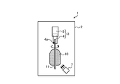
- FIG. 1 is a diagram for explaining the configuration of the optical glass manufacturing apparatus according to the first embodiment.
- FIG. 2 is a diagram for explaining the configuration of the optical glass manufacturing apparatus according to the first embodiment.
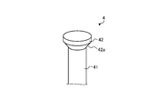
- FIG. 3 is a diagram for explaining the configuration of the first member according to the first embodiment.
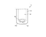
- FIG. 4 is a diagram for explaining the configuration of the second member according to the first embodiment.
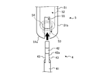
- FIG. 5 is a diagram for explaining a method of supporting the first member with respect to the second member according to the first embodiment.
- FIG. 6 is a diagram for explaining a support structure of the first member with respect to the second member according to the first embodiment.
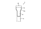
- FIG. 7 is a diagram for explaining the configuration of the first member according to the first modification of the first embodiment.
- FIG. 1 is a diagram for explaining the configuration of the optical glass manufacturing apparatus according to the first embodiment.
- FIG. 2 is a diagram for explaining the configuration of the optical glass manufacturing apparatus according to the first embodiment.
- FIG. 3 is a diagram for explaining the configuration of the first member according to the first
- FIG. 8 is a diagram for explaining the configuration of the second member according to the first modification of the first embodiment.
- FIG. 9 is a diagram for explaining a method of supporting the first member with respect to the second member according to the first modification of the first embodiment.
- FIG. 10 is a diagram for explaining a support structure of the first member with respect to the second member according to the first modification of the first embodiment.
- FIG. 11 is a diagram for explaining the configuration of the first member according to the second modification of the first embodiment.
- FIG. 12 is a diagram for explaining the configuration of the optical glass manufacturing apparatus according to the second embodiment.
- FIG. 13 is a diagram for explaining the configuration of the optical glass manufacturing apparatus according to the second embodiment.
- FIG. 14 is a diagram for explaining the configuration of the first member according to the second embodiment.
- FIG. 15 is a diagram for explaining the configuration of the second member according to the second embodiment.
- FIG. 16 is a diagram for explaining a method of installing the cover member with respect to the second member according to the second embodiment.
- FIG. 17 is a diagram for explaining a method of supporting the first member with respect to the second member according to the second embodiment.
- FIG. 18 is a diagram for explaining the structure of the support member according to the second embodiment.
- FIG. 19 is a diagram for explaining the configuration of the first member according to the first modification of the second embodiment.
- FIG. 20 is a diagram for explaining the configuration of the second member according to the first modification of the second embodiment.
- FIG. 21 is a diagram for explaining a method of supporting the first member with respect to the second member according to the first modification of the second embodiment.
- FIG. 22 is a diagram for explaining the structure of the support member according to the first modification of the second embodiment.
- FIG. 23 is a diagram for explaining the configuration of the first member according to the second modification of the second embodiment.
- FIG. 24 is a diagram for explaining the configuration of the second member according to the second modification of the second embodiment.
- FIG. 25 is a diagram for explaining a method of supporting the first member with respect to the second member according to the second modification of the second embodiment.
- FIG. 26 is a diagram for explaining the structure of the support member according to the second embodiment.
- FIG. 27 is a diagram for explaining a labyrinth structure in the support member according to the second embodiment.
- FIG. 28 is a diagram for explaining the configuration of the first member according to the third modification of the second embodiment.
- FIG. 29 is a diagram for explaining a method of installing the cover member with respect to the second member according to the third modification of the second embodiment.
- FIG. 30 is a diagram for explaining the structure of the support member according to the third modification of the second embodiment.
- FIG. 31 is a diagram for explaining a method of supporting the first member with respect to the second member according to the modified example 4 of the second embodiment.
- FIG. 32 is a diagram for explaining a method of supporting the first member with respect to the second member according to the modified example 5 of the second embodiment.
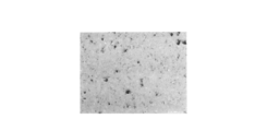
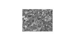
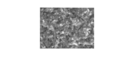
- FIG. 33 is a diagram showing an SEM observation photograph of the polished surface on the outer peripheral side of the support member.
- FIG. 34 is a diagram showing an SEM observation photograph of the polished surface at the center of the support member.
- FIG. 35 is a diagram showing an SEM observation photograph of the polished surface on the inner peripheral side of the support member.
- FIG. 36 is a diagram showing an SEM observation photograph of a fracture surface on the outer peripheral side of the support member.
- FIG. 37 is a diagram showing an SEM observation photograph of the fracture surface of the central portion of the support member.
- FIG. 38 is a diagram showing an SEM observation photograph of a fracture surface on the inner peripheral side of the support member.
- a member used in an optical glass manufacturing apparatus for manufacturing optical glass (hereinafter, also referred to as a member for an optical glass manufacturing apparatus) is exposed to a corrosive gas in a high temperature environment in the process of manufacturing the optical glass. There is.
- halogen elements for example, F (fluorine), Cl (chlorine), Br (bromine)
- F fluorine
- Cl chlorine
- Br bromine
- FIGS. 1 and 2 are diagrams for explaining the configuration of the optical glass manufacturing apparatus 1 according to the first embodiment.
- FIG. 1 shows an initial stage in the manufacturing process of the optical glass 10
- FIG. 2 shows a late stage in the manufacturing process of the optical glass 10.
- the optical glass manufacturing apparatus 1 includes a high temperature furnace 2, a support member 3, and a raw material supply unit 7, and supplies the support member 3 and the raw material to the inside of the high temperature furnace 2.
- a part 7 is provided.
- the support member 3 is an example of a member for an optical glass manufacturing apparatus.
- the high temperature furnace 2 can form a high temperature environment (for example, a temperature of 1100 ° C. to 1600 ° C.) required in the manufacturing process of the optical glass 10 inside.
- a high temperature environment for example, a temperature of 1100 ° C. to 1600 ° C.
- the support member 3 includes a first member 4 and a second member 5, and supports a glass rod 11 which is a starting material of the optical glass 10. For example, an insertion portion 4a through which the glass rod 11 can be inserted is formed in the first member 4. Then, the first member 4 supports the glass rod 11 so as to be suspended by the insertion portion 4a.
- the first member 4 indirectly supports the optical glass 10 being processed.
- the method of supporting the glass rod 11 by the first member 4 is not limited to the above method.
- the optical glass 10 being processed may be directly supported by the first member 4.
- the ingot of the optical glass 10 may be directly supported by the first member 4.
- the second member 5 supports the first member 4 so as to suspend it. Then, the support member 3 is configured so that the supported glass rod 11 can be rotated. The details of the support structure of the first member 4 with respect to the second member 5 will be described later.
- Material supply portion 7 the raw material of the optical glass 10 (e.g., SiClO 4, H 2, etc. O 2) can be supplied configured toward the glass rod 11 a. Further, the raw material supply unit 7 directs a gas containing a halogen element (for example, F 2 gas, Cl 2 gas, GeCl 4 gas, Br 2 gas, etc.) toward the glass rod 11 as a raw material for the additive element in the optical glass 10. Configured to be supplyable. Further, the raw material supply unit 7 is configured to be movable inside the high temperature furnace 2.
- a gas containing a halogen element for example, F 2 gas, Cl 2 gas, GeCl 4 gas, Br 2 gas, etc.
- the inside of the high temperature furnace 2 is maintained at a predetermined temperature, and the raw material of the optical glass 10 is supplied from the raw material supply unit 7 toward the glass rod 11, so that the glass as a starting material is used.
- the optical glass 10 is formed on the surface of the rod 11.
- the optical glass 10 can be grown around the glass rod 11 as shown in FIG.
- the optical glass 10 according to the first embodiment is, for example, a microlens, a photomask, a selective absorption transparent glass, an optical fiber, or the like.
- various characteristics of the optical glass 10 are obtained by setting the inside of the high temperature furnace 2 to a high temperature environment of 1100 ° C. to 1600 ° C. and supplying a gas containing a halogen element from the raw material supply unit 7. (For example, refractive index, etc.) can be controlled.
- the support member 3 includes a first member 4 that directly or indirectly supports the optical glass 10 and a second member 5 that supports the first member 4.
- the processing of the optical glass 10 can be continued only by replacing a part of the support member 3 (the first member 4). Such costs can be reduced. Therefore, according to the first embodiment, the manufacturing cost of the optical glass 10 can be reduced.
- corrosion is a phenomenon in which the weight of a member is reduced by reacting with a gas containing a halogen element, and at the same time, the porosity of the member is increased.
- the first member 4 of the support member 3 is made of dense ceramics containing silicon nitride (Si 3 N 4) as a main component.
- Si 3 N 4 silicon nitride
- the frequency of replacement of the first member 4 can be reduced, so that the manufacturing cost of the optical glass 10 can be further reduced.
- the second member 5 of the support member 3 is made of dense ceramics containing silicon nitride as a main component.
- the corrosion resistance to a gas containing a halogen element can be improved.
- the frequency of replacement of the second member 5 can be reduced, so that the manufacturing cost of the optical glass 10 can be further reduced.
- the second member 5 since the second member 5 is arranged farther from the optical glass 10 than the first member 4, it does not necessarily have to be made of silicon nitride, and is made of, for example, metal. May be done.
- the porosity of the surface layer of the dense ceramic is inside. It should be smaller than the porosity of.
- the surface layer may be a region within 2 mm in the depth direction from the surface. Further, the inside may be a region deeper than 2 mm in the depth direction from the surface.
- the corrosion resistance of the support member 3 can be improved.
- the internal porosity of the dense ceramics larger than that of the surface layer, the growth of cracks from the surface layer can be stopped by the internal pores, so that the heat impact resistance of the support member 3 is improved. Can be improved.
- the internal thermal conductivity can be reduced by making the internal porosity of the dense ceramics larger than that of the surface layer, heat is transferred from the glass rod 11 via the support member 3. It is possible to suppress the escape.
- the temperature of the optical glass 10 formed on the glass rod 11 can be stabilized, so that the optical glass 10 can be stably manufactured.
- the porosity of the surface layer of the dense ceramic is determined. It is preferably 1 (area%) to 3 (area%).
- the support member 3 By forming the support member 3 with the dense ceramics having a small surface porosity in this way, it is possible to make it more difficult for the corrosive gas containing a halogen element to enter the inside through the pores.
- the corrosion resistance of the support member 3 can be further improved.
- the internal porosity of the dense ceramic is determined. It is preferably 4 (area%) to 9 (area%).
- the support member 3 By constructing the support member 3 with the dense ceramics having a relatively large internal porosity in this way, the thermal shock resistance of the support member 3 can be further improved, and the optical glass 10 can be manufactured more stably. be able to.
- the average crystal grain size of the surface layer of the dense ceramic is formed. However, it is preferable that it is larger than the average crystal grain size inside.
- the support member 3 By constructing the support member 3 with such dense ceramics, the total length of the crystal grain boundaries in the surface layer can be shortened, so that it is difficult for corrosive gas containing a halogen element to enter the inside from the crystal grain boundaries. be able to.
- the corrosion resistance of the support member 3 can be improved.
- the oxygen content of the surface layer of the dense ceramic is high. , Should be less than the internal oxygen content.
- the support member 3 By constructing the support member 3 with such dense ceramics, it is possible to suppress the reaction between the gas containing a halogen element (for example, chlorine) that easily reacts with oxygen and the oxygen existing on the surface layer.
- a halogen element for example, chlorine
- the corrosion resistance of the support member 3 it is possible to prevent the surface layer of the dense ceramic from being corroded by the corrosive gas that easily reacts with oxygen, so that the corrosion resistance of the support member 3 can be improved.
- the oxygen content of the surface layer of the dense ceramic is high. It is preferably 7.0 (mass%) or less, and more preferably the oxygen content of the surface layer in the dense ceramic is 6.5 (mass%) or less.
- the internal oxygen content of the dense ceramic is preferably 7.1 (mass%) or more.
- the aluminum content of the surface layer in the dense ceramics is high. , Should be less than the internal aluminum content.
- the support member 3 By constructing the support member 3 with such dense ceramics, it is possible to suppress the reaction between the gas containing a halogen element (for example, chlorine) that easily reacts with aluminum and the aluminum existing on the surface layer.
- a halogen element for example, chlorine
- the corrosion resistance of the support member 3 it is possible to prevent the surface layer of the dense ceramic from being corroded by the corrosive gas that easily reacts with aluminum, so that the corrosion resistance of the support member 3 can be improved.
- alumina Al 2 O 3
- sintering aid when sintering silicon nitride, which is the main component, in the dense ceramics constituting the support member 3, the surface layer and the inside of the dense ceramics.
- FIG. 3 is a diagram for explaining the configuration of the first member 4 according to the first embodiment, and is an enlarged view of an upper end portion (that is, a portion supported by the second member 5) of the first member 4. ..
- the first member 4 has a main body portion 41 and a diameter-expanded portion 42.
- the main body 41 is a columnar portion, for example, a columnar portion.
- the enlarged diameter portion 42 is provided at the upper end portion of the main body portion 41 and has a larger outer diameter than the main body portion 41.
- the enlarged diameter portion 42 has a tapered contact portion 42a at a portion connected to the main body portion 41.
- the contact portion 42a is a portion that comes into contact with the second member 5 when the first member 4 is supported by the second member 5.
- FIG. 4 is a diagram for explaining the configuration of the second member 5 according to the first embodiment, and is an enlarged view of a lower end portion (that is, a portion supporting the first member 4) of the second member 5.
- the second member 5 has a main body portion 51, a cavity portion 52, an opening portion 53, and a locking portion 54.
- the main body 51 is a columnar portion, for example, a columnar portion.
- the cavity 52 is a columnar cavity formed inside the main body 51 so as to extend in the same direction as the longitudinal direction of the main body 51.
- the inner diameter of the hollow portion 52 is larger than the outer diameter of the main body portion 41 and the outer diameter of the enlarged diameter portion 42 in the first member 4.
- the opening 53 is a portion that penetrates between the hollow portion 52 and the bottom surface 51a of the main body portion 51 in a columnar shape.
- the inner diameter of the opening 53 is smaller than the inner diameter of the cavity 52. Further, the inner diameter of the opening 53 is larger than the outer diameter of the main body 41 in the first member 4 and smaller than the outer diameter of the enlarged diameter portion 42.
- the locking portion 54 is a tapered portion adjacent to the upper end of the opening 53.
- the locking portion 54 is a portion that comes into contact with the contact portion 42a of the first member 4 when the first member 4 is supported by the second member 5.
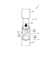
- FIG. 5 is a diagram for explaining a method of supporting the first member 4 with respect to the second member 5 according to the first embodiment. As shown in FIG. 5, when the first member 4 is supported with respect to the second member 5, the entire first member 4 is inserted downward into the cavity 52 of the second member 5.
- the first member 4 is inserted into the hollow portion 52 of the second member 5 with the enlarged diameter portion 42 of the first member 4 facing upward and the opening 53 of the second member 5 facing downward. NS. Then, the main body 41 of the first member 4 is inserted into the opening 53 of the second member 5.
- FIG. 6 is a diagram for explaining a support structure of the first member 4 with respect to the second member 5 according to the first embodiment.
- the contact portion 42a of the first member 4 comes into contact with the locking portion 54 of the second member 5, so that the first member 4 is supported by the second member 5, while these The engaging part of is not fixed with an adhesive or the like. As a result, the first member 4 can swing with respect to the second member 5.
- the first member 4 can be supported substantially vertically. Therefore, according to the first embodiment, since the glass rod 11 supported by the first member 4 can also be supported substantially vertically, the optical glass 10 can be stably grown around the glass rod 11. ..
- At least one of the contact portion 42a of the first member 4 and the locking portion 54 of the second member 5 may have a tapered shape or a spherical shape. As a result, the first member 4 can be made swingable with respect to the second member 5 more easily.
- the first member 4 and the glass rod 11 can be more easily supported substantially vertically, so that the glass can be supported.
- the optical glass 10 can be grown more stably around the rod 11.
- FIG. 7 is a diagram for explaining the configuration of the first member 4 according to the first modification of the first embodiment, and is a diagram of an upper end portion (that is, a portion supported by the second member 5) of the first member 4. It is an enlarged view.
- the first member 4 of the first modification of the first embodiment has a main body portion 41, a diameter-expanded portion 42, and a pair of notched portions 43.
- the main body 41 is a columnar portion, for example, a columnar portion.
- the enlarged diameter portion 42 is provided at the upper end portion of the main body portion 41 and has a portion having a larger outer diameter than the main body portion 41.
- the enlarged diameter portion 42 has a tapered contact portion 42a at a portion connected to the main body portion 41.
- the contact portion 42a is a portion that comes into contact with the second member 5 when the first member 4 is supported by the second member 5.
- the notch portion 43 is a portion that is notched flat from the enlarged diameter portion 42 of the first member 4 to the upper part of the main body portion 41.
- the pair of notches 43 are notched substantially parallel to each other.
- FIG. 8 is a diagram for explaining the configuration of the second member 5 according to the modified example 1 of the first embodiment, and is an enlargement of the lower end portion (that is, the portion supporting the first member 4) of the second member 5. It is a figure.
- the second member 5 of the first modification of the first embodiment has a main body portion 51, a cavity portion 52, an opening portion 53, a locking portion 54, and a slit 55.
- the main body 51 is a columnar portion, for example, a columnar portion.
- the cavity 52 is a columnar cavity formed inside the main body 51 so as to extend in the same direction as the longitudinal direction of the main body 51.
- the inner diameter of the hollow portion 52 is larger than the major diameter of the main body portion 41 and the enlarged diameter portion 42 in the first member 4 (that is, the outer diameter of the portion not cut out in the cutout portion 43).
- the opening 53 is a portion that penetrates between the hollow portion 52 and the bottom surface 51a of the main body portion 51 in a columnar shape.
- the inner diameter of the opening 53 is smaller than the inner diameter of the cavity 52. Further, the inner diameter of the opening 53 is larger than the major axis of the main body 41 in the first member 4 and smaller than the major axis of the enlarged diameter portion 42.
- the locking portion 54 is a tapered portion adjacent to the upper end of the opening 53.
- the locking portion 54 is a portion that comes into contact with the contact portion 42a of the first member 4 when the first member 4 is supported by the second member 5.
- the slit 55 is formed on the side surface 51b of the main body 51 so as to be connected to the cavity 52 and the opening 53.
- the slit 55 is formed so as to extend in the same direction as the longitudinal direction of the main body 51.
- the width of the slit 55 is larger than the short diameter of the main body portion 41 and the enlarged diameter portion 42 in the first member 4 (that is, the outer diameter of the portion cut out by the cutout portion 43), and the main body portion 41 and It is smaller than the major axis of the enlarged diameter portion 42.
- FIG. 9 is a diagram for explaining a method of supporting the first member 4 with respect to the second member 5 according to the first modification of the first embodiment. As shown in FIG. 9, when the first member 4 is supported with respect to the second member 5, the portion cut out by the notch 43 at the upper end of the first member 4 is the second member 5. It is inserted sideways into the slit 55.
- the upper end portion of the first member 4 becomes a slit 55 of the second member 5. Will be inserted. Then, the enlarged diameter portion 42 of the first member 4 is inserted into the hollow portion 52 of the second member 5.
- FIG. 10 is a diagram for explaining a support structure of the first member 4 with respect to the second member 5 according to the first modification of the first embodiment.
- the first member 4 is supported by the second member 5 by abutting the contact portion 42a of the first member 4 with the locking portion 54 of the second member 5.
- these engaging parts are not fixed with an adhesive or the like. As a result, the first member 4 can swing with respect to the second member 5.
- the first member 4 can be supported substantially vertically. Therefore, according to the first modification of the first embodiment, the glass rod 11 supported by the first member 4 can also be supported substantially vertically, so that the optical glass 10 can be stably grown around the glass rod 11. Can be made to.
- At least one of the contact portion 42a of the first member 4 and the locking portion 54 of the second member 5 may have a tapered shape or a spherical shape. As a result, the first member 4 can be made swingable with respect to the second member 5 more easily.
- the optical glass 10 can be grown more stably around the glass rod 11.
- FIG. 11 is a diagram for explaining the configuration of the first member 4 according to the modified example 2 of the first embodiment.
- the hollow portion 41a which is a cavity, is arranged inside the main body portion 41 of the first member 4.
- the hollow portion 41a is arranged in the first member 4, the load applied to the connecting portion connecting the first member 4 and the second member 5 can be reduced. Therefore, it is possible to prevent the first member 4 from becoming difficult to swing with respect to the second member 5.
- a member used in an optical glass manufacturing apparatus for manufacturing optical glass (hereinafter, also referred to as a member for an optical glass manufacturing apparatus) is exposed to a corrosive gas in a high temperature environment in the process of manufacturing the optical glass. There is.
- halogen elements for example, F (fluorine), Cl (chlorine), Br (bromine)
- F fluorine
- Cl chlorine
- Br bromine
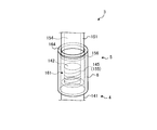
- FIGS. 12 and 13 are diagrams for explaining the configuration of the optical glass manufacturing apparatus 1 according to the second embodiment.
- FIG. 12 shows an initial stage in the manufacturing process of the optical glass 10
- FIG. 13 shows a late stage in the manufacturing process of the optical glass 10.
- the optical glass manufacturing apparatus 1 includes a high temperature furnace 2, a support member 3, and a raw material supply unit 7, and supplies the support member 3 and the raw material to the inside of the high temperature furnace 2.
- a part 7 is provided.
- the support member 3 is an example of a member for an optical glass manufacturing apparatus.
- the high temperature furnace 2 can form a high temperature environment (for example, a temperature of 1100 ° C. to 1600 ° C.) required in the manufacturing process of the optical glass 10 inside.
- a high temperature environment for example, a temperature of 1100 ° C. to 1600 ° C.
- the support member 3 includes a first member 4, a second member 5, and a cover member 6, and supports a glass rod 11 which is a starting material of the optical glass 10.
- a glass rod 11 which is a starting material of the optical glass 10.
- an insertion portion 4a through which the glass rod 11 can be inserted is formed in the first member 4.
- the first member 4 supports the glass rod 11 so as to be suspended by the insertion portion 4a.
- the first member 4 indirectly supports the optical glass 10 being processed.
- the method of supporting the glass rod 11 by the first member 4 is not limited to the above method.
- the optical glass 10 being processed may be directly supported by the first member 4.
- the ingot of the optical glass 10 may be directly supported by the first member 4.
- the second member 5 supports the first member 4 so as to suspend it.
- the cover member 6 covers the connecting portion connecting the first member 4 and the second member 5. Then, the support member 3 is configured so that the supported glass rod 11 can be rotated. The details of the first member 4, the second member 5, and the cover member 6 will be described later.
- Material supply portion 7 the raw material of the optical glass 10 (e.g., SiClO 4, H 2, etc. O 2) can be supplied configured toward the glass rod 11 a. Further, the raw material supply unit 7 directs a gas containing a halogen element (for example, F 2 gas, Cl 2 gas, GeCl 4 gas, Br 2 gas, etc.) toward the glass rod 11 as a raw material for the additive element in the optical glass 10. Configured to be supplyable. Further, the raw material supply unit 7 is configured to be movable inside the high temperature furnace 2.
- a gas containing a halogen element for example, F 2 gas, Cl 2 gas, GeCl 4 gas, Br 2 gas, etc.
- the inside of the high temperature furnace 2 is maintained at a predetermined temperature, and the raw material of the optical glass 10 is supplied from the raw material supply unit 7 toward the glass rod 11, so that the glass as a starting material is used.
- the optical glass 10 is formed on the surface of the rod 11.
- the optical glass 10 can be grown around the glass rod 11 as shown in FIG.
- the optical glass 10 according to the second embodiment is, for example, a microlens, a photomask, a selective absorption transparent glass, an optical fiber, or the like.
- various characteristics of the optical glass 10 are obtained by setting the inside of the high temperature furnace 2 to a high temperature environment of 1100 ° C. to 1600 ° C. and supplying a gas containing a halogen element from the raw material supply unit 7. (For example, refractive index, etc.) can be controlled.
- the support member 3 includes a first member 4 that directly or indirectly supports the optical glass 10, a second member 5 that supports the first member 4, and a first member 4.
- a cover member 6 for covering the connecting portion connecting the second member 5 and the second member 5 is provided.
- the processing of the optical glass 10 can be continued only by replacing a part of the support member 3 (cover member 6), so that the support member 3 needs to be replaced.
- the cost can be reduced. Therefore, according to the second embodiment, the manufacturing cost of the optical glass 10 can be reduced.
- corrosion is a phenomenon in which the weight of a member is reduced by reacting with a gas containing a halogen element, and at the same time, the porosity of the member is increased.
- the connecting portion connecting the first member 4 and the second member 5, which are easily corroded due to external stress, is protected by the cover member 6. can. Therefore, according to the second embodiment, deterioration of the connection portion can be suppressed.
- the cover member 6 of the support member 3 may be made of dense ceramics containing silicon nitride (Si 3 N 4) as a main component.
- Si 3 N 4 silicon nitride
- the frequency of replacement of the cover member 6 can be reduced, so that the manufacturing cost of the optical glass 10 can be further reduced.
- the first member 4 of the support member 3 is made of dense ceramics containing silicon nitride (Si 3 N 4) as a main component.
- Si 3 N 4 silicon nitride
- the frequency of replacement of the first member 4 can be reduced, so that the manufacturing cost of the optical glass 10 can be further reduced.
- the first member 4 since the first member 4 has a smaller specific surface area than the cover member 6, it does not necessarily have to be made of silicon nitride, and may be made of, for example, metal.
- the second member 5 of the support member 3 is made of dense ceramics containing silicon nitride as a main component.
- the corrosion resistance to a gas containing a halogen element can be improved.
- the frequency of replacement of the second member 5 can be reduced, so that the manufacturing cost of the optical glass 10 can be further reduced.
- the second member 5 since the second member 5 is arranged farther from the optical glass 10 than the cover member 6, it does not necessarily have to be made of silicon nitride, and is made of, for example, metal. You may.
- the first member 4 and the second member 5 when at least one of the cover member 6, the first member 4 and the second member 5 is made of a dense ceramic containing silicon nitride as a main component, the surface layer of the dense ceramic is formed.
- the porosity should be smaller than the internal porosity.
- the surface layer may be a region within 2 mm in the depth direction from the surface. Further, the inside may be a region deeper than 2 mm in the depth direction from the surface.
- the corrosion resistance of the support member 3 can be improved.
- the internal porosity of the dense ceramics larger than that of the surface layer, the growth of cracks from the surface layer can be stopped by the internal pores, so that the heat impact resistance of the support member 3 is improved. Can be improved.
- the internal thermal conductivity can be reduced by making the internal porosity of the dense ceramics larger than that of the surface layer, heat is transferred from the glass rod 11 via the support member 3. It is possible to suppress the escape.
- the temperature of the optical glass 10 formed on the glass rod 11 can be stabilized, so that the optical glass 10 can be stably manufactured.
- the surface layer of the dense ceramic is formed.
- the porosity is preferably 1 (area%) to 3 (area%).
- the support member 3 By forming the support member 3 with the dense ceramics having a small surface porosity in this way, it is possible to make it more difficult for the corrosive gas containing a halogen element to enter the inside through the pores.
- the corrosion resistance of the support member 3 can be further improved.
- the first member 4 and the second member 5 is made of a dense ceramic containing silicon nitride as a main component
- the inside of the dense ceramic The porosity is preferably 4 (area%) to 9 (area%).
- the support member 3 By constructing the support member 3 with the dense ceramics having a relatively large internal porosity in this way, the thermal shock resistance of the support member 3 can be further improved, and the optical glass 10 can be manufactured more stably. be able to.
- the first member 4 and the second member 5 is made of a dense ceramic containing silicon nitride as a main component, the surface layer of the dense ceramic is formed. It is preferable that the average crystal grain size is larger than the internal average crystal grain size.
- the support member 3 By constructing the support member 3 with such dense ceramics, the total length of the crystal grain boundaries in the surface layer can be shortened, so that it is difficult for corrosive gas containing a halogen element to enter the inside from the crystal grain boundaries. be able to.
- the corrosion resistance of the support member 3 can be improved.
- the first member 4 and the second member 5 when at least one of the cover member 6, the first member 4 and the second member 5 is made of a dense ceramic containing silicon nitride as a main component, the surface layer of the dense ceramic is formed.
- the oxygen content should be less than the internal oxygen content.
- the support member 3 By constructing the support member 3 with such dense ceramics, it is possible to suppress the reaction between the gas containing a halogen element (for example, chlorine) that easily reacts with oxygen and the oxygen existing on the surface layer.
- a halogen element for example, chlorine
- the corrosion resistance of the support member 3 it is possible to prevent the surface layer of the dense ceramic from being corroded by the corrosive gas that easily reacts with oxygen, so that the corrosion resistance of the support member 3 can be improved.
- the first member 4 and the second member 5 is made of a dense ceramic containing silicon nitride as a main component
- the surface layer of the dense ceramic is formed.
- the oxygen content is preferably 7.0 (mass%) or less, and more preferably the oxygen content of the surface layer of the dense ceramic is 6.5 (mass%) or less.
- the internal oxygen content of the dense ceramic is preferably 7.1 (mass%) or more.
- the first member 4 and the second member 5 when at least one of the cover member 6, the first member 4 and the second member 5 is made of a dense ceramic containing silicon nitride as a main component, the surface layer of the dense ceramic is formed.
- the aluminum content should be less than the internal aluminum content.
- the support member 3 By constructing the support member 3 with such dense ceramics, it is possible to suppress the reaction between the gas containing a halogen element (for example, chlorine) that easily reacts with aluminum and the aluminum existing on the surface layer.
- a halogen element for example, chlorine
- the corrosion resistance of the support member 3 it is possible to prevent the surface layer of the dense ceramics from being corroded by the corrosive gas that easily reacts with aluminum, so that the corrosion resistance of the support member 3 can be improved.
- alumina Al 2 O 3
- sintering aid when sintering silicon nitride, which is the main component, in the dense ceramics constituting the support member 3, the surface layer and the inside of the dense ceramics.
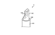
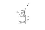
- FIG. 14 is a diagram for explaining the configuration of the first member 4 according to the second embodiment, and is an enlarged view of an upper end portion (that is, a portion supported by the second member 5) of the first member 4. ..
- the first member 4 has a main body portion 141, a narrow diameter portion 142, a step portion 143, and a support portion 144.
- the main body portion 141 is a columnar portion, for example, a columnar portion.
- the narrow diameter portion 142 is provided at the upper end portion of the main body portion 141, and is a portion having an outer diameter smaller than that of the main body portion 141.
- the step portion 143 is formed on the side surface of the narrow diameter portion 142, and has steps having different heights toward the sides.
- the support portion 144 is an annular flat surface located between the main body portion 141 and the narrow diameter portion 142. The support portion 144 is a portion that comes into contact with the bottom surface 163 (see FIG. 16) of the cover member 6 when the cover member 6 is supported by the first member 4.
- FIG. 15 is a diagram for explaining the configuration of the second member 5 according to the second embodiment, and is an enlarged view of a lower end portion (that is, a portion supporting the first member 4) of the second member 5.
- the second member 5 has a main body portion 151, a narrow diameter portion 152, and a step portion 153.
- the main body portion 151 is a columnar portion, for example, a columnar portion.
- the narrow diameter portion 152 is provided at the lower end portion of the main body portion 151, and is a portion having an outer diameter smaller than that of the main body portion 151. Further, the outer diameter of the narrow diameter portion 152 is substantially equal to the outer diameter of the narrow diameter portion 142 in the first member 4.
- the step portion 153 is formed on the side surface of the narrow diameter portion 152, and has steps having different heights toward the sides. Further, the step portion 153 has a shape that fits the step shape of the step portion 143 in the first member 4.
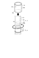
- FIG. 16 is a diagram for explaining a method of installing the cover member 6 with respect to the second member 5 according to the second embodiment.
- the cover member 6 has a substantially cylindrical shape, and has a main body portion 161, a hollow portion 162, and a bottom surface 163.
- the main body portion 161 is a columnar portion, for example, a columnar portion.
- the cavity portion 162 is a columnar cavity formed inside the main body portion 161 so as to extend in the same direction as the longitudinal direction of the main body portion 161.
- the inner diameter of the hollow portion 162 is larger than the outer diameter of the narrow diameter portion 142 of the first member 4 and the outer diameter of the narrow diameter portion 152 of the second member 5. Further, the inner diameter of the cavity portion 162 is smaller than the outer diameter of the main body portion 141 of the first member 4.
- the cover member 6 when the cover member 6 is installed with respect to the second member 5, the cover member 6 is inserted upward into the narrow diameter portion 152 of the second member 5.
- the portion of the narrow diameter portion 152 on the proximal end side of the step portion 153 is longer than that of the cover member 6.
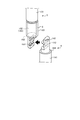
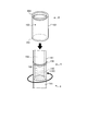
- FIG. 17 is a diagram for explaining a method of supporting the first member 4 with respect to the second member 5 according to the second embodiment.
- the step portion 143 of the first member 4 is fitted laterally to the step portion 153 of the second member 5.
- the narrow diameter portion 142 of the first member 4 and the narrowness of the second member 5 are narrowed. It is configured so that the diameter portion 152 and the diameter portion 152 form a cylinder having an even outer diameter.
- the cover member 6 can be inserted into the narrow diameter portion 142 of the first member 4. Then, in the second embodiment, since the cover member 6 is longer than the narrow diameter portion 142 of the first member 4, when the bottom surface 163 of the cover member 6 is supported by the support portion 144 of the first member 4, the first member 4 is supported.
- the connecting portion here, the stepped portions 143 and 153 and their periphery connecting the first member 4 and the second member 5 can be covered with the cover member 6.
- the connecting portions stepped portions 143 and 153 that are easily corroded due to external stress can be protected by the cover member 6. Therefore, according to the second embodiment, deterioration of the connection portion can be suppressed.
- the support member 3 when the support member 3 is corroded by a corrosive gas during the treatment of the optical glass 10, only the cover member 6 which is close to the optical glass 10 and has a large specific surface area and therefore has a corrosive reaction has progressed.
- the processing of the optical glass 10 can be continued by exchanging.
- the processing of the optical glass 10 can be continued only by replacing a part of the support member 3 (cover member 6), so that the support member 3 needs to be replaced.
- the cost can be reduced. Therefore, according to the second embodiment, the manufacturing cost of the optical glass 10 can be reduced.
- FIG. 19 is a diagram for explaining the configuration of the first member 4 according to the modified example 1 of the second embodiment, and is a diagram of an upper end portion (that is, a portion supported by the second member 5) of the first member 4. It is an enlarged view.
- the first member 4 of the first modification of the second embodiment has a main body portion 141, a narrow diameter portion 142, a support portion 144, and a male screw portion 145.
- the main body portion 141 is a columnar portion, for example, a columnar portion.
- the narrow diameter portion 142 is provided at the upper end portion of the main body portion 141, and is a portion having an outer diameter smaller than that of the main body portion 141.
- the support portion 144 is an annular protrusion provided at a predetermined position on the side surface of the main body portion 141.
- the support portion 144 is a portion that comes into contact with the bottom surface 163 (see FIG. 21) of the cover member 6 when the cover member 6 is supported by the first member 4.
- the male screw portion 145 is a spiral groove formed on the side surface of the narrow diameter portion 142, and functions as a male screw.
- FIG. 20 is a diagram for explaining the configuration of the second member 5 according to the modified example 1 of the second embodiment, and is an enlargement of the lower end portion (that is, the portion supporting the first member 4) of the second member 5. It is a figure.
- the second member 5 of the modified example 1 of the second embodiment has a main body portion 151, a cavity portion 154, and a female screw portion 155.
- the main body portion 151 is a columnar portion, for example, a columnar portion. Further, the outer diameter of the main body portion 151 is substantially equal to the outer diameter of the main body portion 141 in the first member 4.
- the cavity portion 154 is a columnar cavity formed inside the main body portion 151 so as to extend in the same direction as the longitudinal direction of the main body portion 151.
- the female screw portion 155 is a spiral groove formed on the inner surface of the cavity portion 154 on the tip end side, and functions as a female screw capable of screwing the male screw portion 145 of the first member 4.
- FIG. 21 is a diagram for explaining a method of supporting the first member 4 with respect to the second member 5 according to the modified example 1 of the second embodiment. As shown in FIG. 21, when the first member 4 is supported with respect to the second member 5, the male screw portion 145 of the first member 4 is screwed to the female screw portion 155 of the second member 5.
- the cover member 6 of the modified example 1 of the second embodiment has a substantially cylindrical shape, and has a main body portion 161, a hollow portion 162, and a bottom surface 163.
- the main body portion 161 is a columnar portion, for example, a columnar portion.
- the cavity portion 162 is a columnar cavity formed inside the main body portion 161 so as to extend in the same direction as the longitudinal direction of the main body portion 161.
- the inner diameter of the hollow portion 162 is slightly larger than the outer diameter of the main body portion 141 of the first member 4 and the outer diameter of the main body portion 151 of the second member 5. Further, the inner diameter of the cavity portion 162 is smaller than the outer diameter of the support portion 144 of the first member 4.
- the cover member 6 is installed on the first member 4 and the second member 5, the cover member 6 is inserted downward into the main body portion 151 of the second member 5.
- the length from the support portion 144 of the first member 4 to the tip end portion of the second member 5 is shorter than that of the cover member 6.
- FIG. 22 is a diagram for explaining the structure of the support member 3 according to the first modification of the second embodiment.
- connection portion the tip portion of the second member 5 that is easily corroded due to external stress can be protected by the cover member 6. Therefore, according to the first modification of the second embodiment, it is possible to suppress the deterioration of the connecting portion.
- the corrosion reaction proceeds because it is close to the optical glass 10 and has a large specific surface area.
- the processing of the optical glass 10 can be continued only by replacing a part (cover member 6) of the support member 3, so that the support member 3 can be continued.
- the cost of replacement of the glass can be reduced. Therefore, according to the first modification of the second embodiment, the manufacturing cost of the optical glass 10 can be reduced.
- FIG. 23 is a diagram for explaining the configuration of the first member 4 according to the modified example 2 of the second embodiment, and is a diagram of an upper end portion (that is, a portion supported by the second member 5) of the first member 4. It is an enlarged view.
- the first member 4 of the second modification of the second embodiment has a main body portion 141, a narrow diameter portion 142, and a male screw portion 145.
- the first member 4 of the modified example 2 of the second embodiment is the same as the first member 4 of the modified example 1 of the second embodiment except that the support portion 144 is not provided. Omit.
- FIG. 24 is a diagram for explaining the configuration of the second member 5 according to the modified example 2 of the second embodiment, and is an enlargement of the lower end portion (that is, the portion supporting the first member 4) of the second member 5. It is a figure.
- the second member 5 of the modified example 1 of the second embodiment has a main body portion 151, a cavity portion 154, a female screw portion 155, and a support portion 156.
- the main body portion 151, the cavity portion 154, and the female screw portion 155 of the modified example 2 of the second embodiment are the same as the respective parts of the second member 5 of the modified example 1 of the second embodiment. Omit.
- the support portion 156 is an annular protrusion provided at a predetermined position on the side surface of the main body portion 151.
- the support portion 156 is a portion that comes into contact with the protruding portion 164 (see FIG. 25) of the cover member 6 when the cover member 6 is supported by the second member 5.
- FIG. 25 is a diagram for explaining a method of supporting the first member 4 with respect to the second member 5 according to the second embodiment. As shown in FIG. 25, when the first member 4 is supported with respect to the second member 5, the male screw portion 145 of the first member 4 is screwed to the female screw portion 155 of the second member 5.
- the cover member 6 of the modified example 2 of the second embodiment has a substantially cylindrical shape, and has a main body portion 161, a hollow portion 162, a bottom surface 163, and a protruding portion 164.
- the main body portion 161 is a columnar portion, for example, a columnar portion.
- the cavity portion 162 is a columnar cavity formed inside the main body portion 161 so as to extend in the same direction as the longitudinal direction of the main body portion 161.
- the protrusion 164 is an annular protrusion provided on the inner surface of the upper end portion of the main body portion 161. That is, a columnar cavity having an inner diameter smaller than that of the cavity 162 is formed in the vicinity of the projecting portion 164.
- the inner diameter of the cavity formed in the vicinity of the protruding portion 164 is slightly larger than the outer diameter of the main body portion 151 of the second member 5. Further, the inner diameter of the cavity is smaller than the outer diameter of the support portion 156 of the second member 5.
- the cover member 6 is installed on the first member 4 and the second member 5, the cover member 6 is inserted downward into the main body portion 151 of the second member 5.
- the length from the support portion 156 of the second member 5 to the tip end portion of the second member 5 is shorter than that of the cover member 6.
- FIG. 26 is a diagram for explaining the structure of the support member 3 according to the modified example 2 of the second embodiment.
- the connecting portion (the tip portion of the second member 5) that is easily corroded due to external stress can be protected by the cover member 6. Therefore, according to the second modification, the deterioration of the connecting portion can be suppressed.
- the corrosion reaction proceeds because it is close to the optical glass 10 and has a large specific surface area.
- the processing of the optical glass 10 can be continued only by replacing a part (cover member 6) of the support member 3, so that the support member 3 can be continued.
- the cost of replacement of the glass can be reduced. Therefore, according to the second modification of the second embodiment, the manufacturing cost of the optical glass 10 can be reduced.
- FIG. 27 is a diagram for explaining the labyrinth structure in the support member 3 according to the modified example 2 of the second embodiment, and is a cross-sectional view showing the vicinity of the support portion 156 of the second member 5. As shown in FIG. 27, in the second modification, it is preferable that the labyrinth structure is provided in the vicinity of the support portion 156 of the second member 5.
- a convex portion 151a1 formed along the circumferential direction is provided at a portion above the support portion 156 of the second member 5. Further, a concave portion 164a1 corresponding to the convex portion 151a1 is formed on the inner side surface 164a of the protruding portion 164 of the cover member 6 facing the convex portion 151a1.
- a labyrinth structure is formed by the convex portion 151a1 of the second member 5 and the concave portion 164a1 of the cover member 6.
- the labyrinth structure formed between the second member 5 and the cover member 6 is not limited to the example of FIG. 27, and any structure can be used as long as the corrosive gas infiltration route is complicated. May be good.
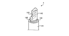
- FIG. 28 is a diagram for explaining the configuration of the first member 4 according to the modified example 3 of the second embodiment, and is a diagram of an upper end portion (that is, a portion supported by the second member 5) of the first member 4. It is an enlarged view.
- the first member 4 has a main body portion 141, a narrow diameter portion 142, a step portion 143, a support portion 144, and a male screw portion 146.
- the main body portion 141, the narrow diameter portion 142, the step portion 143, and the support portion 144 of the modified example 3 of the second embodiment are the same as the respective parts of the first member 4 of the second embodiment. Omit.
- the male screw portion 146 is a spiral groove formed on the side surface of the narrow diameter portion 142, and functions as a male screw.
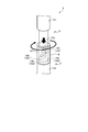
- FIG. 29 is a diagram for explaining a method of installing the cover member 6 with respect to the second member 5 according to the modified example 3 of the second embodiment.
- the second member 5 of the modified example 3 of the second embodiment has a main body portion 151, a narrow diameter portion 152, and a step portion 153. Since the first member 4 of the modified example 3 of the second embodiment is the same as the second member 5 of the second embodiment, detailed description thereof will be omitted.
- the cover member 6 of the modified example 3 of the second embodiment has a substantially cylindrical shape, and has a main body portion 161, a hollow portion 162, a bottom surface 163, and a female screw portion 165. Since the main body portion 161, the cavity portion 162, and the bottom surface 163 of the modified example 3 of the second embodiment are the same as the respective parts of the cover member 6 of the second embodiment, detailed description thereof will be omitted.
- the female screw portion 165 is a spiral groove formed on the inner surface of the lower end side of the cavity portion 162, and functions as a female screw capable of screwing the male screw portion 146 of the first member 4.
- the cover member 6 when the cover member 6 is installed with respect to the second member 5, the cover member 6 is inserted upward into the narrow diameter portion 152 of the second member 5.
- the portion of the narrow diameter portion 152 on the proximal end side of the step portion 153 is longer than that of the cover member 6.
- the step portion 143 of the first member 4 becomes the step portion of the second member 5. It is fitted sideways to 153.
- FIG. 30 is a diagram for explaining the structure of the support member 3 according to the modified example 3 of the second embodiment.
- the cover member 6 is longer than the narrow diameter portion 142 of the first member 4, the bottom surface 163 of the cover member 6 is supported by the support portion 144 of the first member 4.
- the connecting portion here, the stepped portions 143 and 153 and their periphery connecting the first member 4 and the second member 5 can be covered with the cover member 6.
- the optical glass 10 (see FIG. 12) is manufactured from the outside.
- the cover member 6 can protect the connection portion that is easily corroded due to the stress of the above.
- the corrosion reaction proceeds because it is close to the optical glass 10 and has a large specific surface area.
- the processing of the optical glass 10 can be continued.
- the processing of the optical glass 10 can be continued only by replacing a part (cover member 6) of the support member 3, so that the support member 3 can be continued.
- the cost of replacement of the glass can be reduced. Therefore, according to the third modification of the second embodiment, the manufacturing cost of the optical glass 10 can be reduced.
- FIG. 31 is a diagram for explaining a method of supporting the first member 4 with respect to the second member 5 according to the modified example 4 of the second embodiment.
- the claw portion 147 is provided at the upper end portion of the narrow diameter portion 142 of the first member 4, and the lower end of the narrow diameter portion 152 of the second member 5 is provided.
- a claw portion 157 is provided on the portion.
- the first member 4 is supported with respect to the second member 5 by hooking the claw portion 147 of the first member 4 on the claw portion 157 of the second member 5. be able to.
- the connecting portion here, the claw portion 147, 157 and its periphery connecting the first member 4 and the second member 5 is covered. It may be covered with the member 6.
- FIG. 32 is a diagram for explaining a method of supporting the first member 4 with respect to the second member 5 according to the modified example 5 of the second embodiment.
- the claw portion 147 is provided at the upper end portion of the narrow diameter portion 142 of the first member 4, and the lower end of the narrow diameter portion 152 of the second member 5 is provided.
- An arc portion 158 is provided in the portion.
- the first member 4 is supported with respect to the second member 5 by hooking the claw portion 147 of the first member 4 on the arc portion 158 of the second member 5. Can be done.
- the connecting portion connecting the first member 4 and the second member 5 here, the claw portion 147, the arc portion 158 and its surroundings. May be covered with the cover member 6.
- a alumina powder having an average particle size of 1 ⁇ m and an Itria (Y 2 O 3 ) powder having an average particle size of 1 ⁇ m were prepared. Then, each of the prepared powders was mixed at a predetermined ratio to obtain a mixed powder.
- the obtained mixed powder was placed in a barrel mill together with a crushing medium composed of water and a silicon nitride sintered body, and mixed and pulverized until a predetermined particle size was reached. Then, polyvinyl alcohol (PVA), which is an organic binder, was added to the mixed powder that had been mixed and pulverized in a predetermined ratio and mixed to obtain a slurry.
- PVA polyvinyl alcohol
- the obtained slurry was passed through a mesh sieve having a predetermined particle size, and then granulated using a spray-drying granulator to obtain granules. Then, the obtained granules were molded into a predetermined shape by CIP (cold isotropic pressure) molding having a molding pressure of 60 MPa to 100 MPa to obtain a molded product.
- CIP cold isotropic pressure
- the obtained molded product was placed in a silicon carbide brazing bowl and degreased by holding it in a nitrogen atmosphere at 500 ° C. for 5 hours. Subsequently, the temperature was further raised, and nitriding was carried out by sequentially holding at 1050 ° C. for 20 hours and at 1250 ° C. for 10 hours in a nitrogen partial pressure of 150 kPa consisting substantially of nitrogen.
- support members 3 (first member 4 and second member 5) of dense ceramics containing silicon nitride as a main component were obtained.
- any member constituting the support member 3 has a tubular portion.
- the outer peripheral side an example of the surface layer of the support member 3
- the central portion an example of the inside of the support member 3
- the inner peripheral side an example of the surface layer of the support member 3
- the number of pores per unit area for each observation site, the porosity, the average diameter of the pores, and the maximum diameter of the pores were evaluated. Specifically, first, using the obtained SEM observation photograph, the outline of the pores detected in dark color is bordered in black.
- image analysis software "A image-kun” registered trademark, manufactured by Asahi Kasei Engineering Co., Ltd., and subsequently referred to as the image analysis software "A image-kun”” is described using the image or photograph with the border.
- Image analysis software manufactured by Asahi Kasei Engineering Co., Ltd. is applied to perform image analysis, and the number of pores per unit area, the average diameter of the pores, and the maximum diameter of the pores are analyzed. Can be obtained.
- the total area of a plurality of pores is obtained by applying a technique called particle analysis of the image analysis software "A image-kun", and the ratio of the total area of the plurality of pores to the unit area is "porosity". Can be obtained as.
- the oxygen content and the aluminum content on the outer peripheral side, the central portion and the inner peripheral side were evaluated.
- the oxygen content was evaluated by an infrared absorption method using an oxygen analyzer (EMGA-650FA manufactured by HORIBA, Ltd.).
- the aluminum content was evaluated using an ICP (Inductively Coupled Plasma) emission spectroscopic analyzer or a fluorescent X-ray analyzer.
- the porosity of the surface layer (that is, the outer peripheral side and the inner peripheral side) is higher than the porosity of the inside (that is, the central portion). It turns out that is also small. Thereby, in the surface layer directly exposed to the corrosive gas containing a halogen element, it is possible to prevent the corrosive gas from entering the inside through the pores.
- each embodiment it is possible to prevent the inside of the support member 3 from being corroded by the corrosive gas, so that the corrosion resistance of the support member 3 can be improved.
- CIP molding is performed at a high molding pressure (60 MPa to 100 MPa), or firing treatment is performed in a nitrogen atmosphere at normal pressure. Things are effective.
- the average crystal grain size of the surface layer (that is, the outer peripheral side and the inner peripheral side) is the average crystal inside (that is, the central portion). It can be seen that it is larger than the particle size. As a result, the total length of the crystal grain boundaries in the surface layer can be shortened, so that it is possible to prevent corrosive gas containing a halogen element from entering the inside from the crystal grain boundaries.
- each embodiment it is possible to prevent the inside of the support member 3 from being corroded by the corrosive gas, so that the corrosion resistance of the support member 3 can be improved.
- the oxygen content of the surface layer (that is, the outer peripheral side and the inner peripheral side) is smaller than the oxygen content of the inner surface (that is, the central portion). You can see that. This makes it possible to suppress the reaction between the gas containing a halogen element (for example, chlorine) that easily reacts with oxygen and the oxygen existing on the surface layer.
- a halogen element for example, chlorine
- each embodiment it is possible to prevent the surface layer of the support member 3 from being corroded by the corrosive gas that easily reacts with oxygen, so that the corrosion resistance of the support member 3 can be improved.
- the oxygen content of the surface layer (that is, the outer peripheral side and the inner peripheral side) of the support member 3 according to each embodiment is 7.0 (mass%) or less.
- the aluminum content of the surface layer (that is, the outer peripheral side and the inner peripheral side) is smaller than the aluminum content of the inner (that is, the central portion). You can see that. This makes it possible to suppress the reaction between the gas containing a halogen element (for example, chlorine) that easily reacts with aluminum and the aluminum existing on the surface layer.
- a halogen element for example, chlorine
- each embodiment it is possible to prevent the surface layer of the support member 3 from being corroded by the corrosive gas that easily reacts with aluminum, so that the corrosion resistance of the support member 3 can be improved.
Landscapes
- Chemical & Material Sciences (AREA)
- Engineering & Computer Science (AREA)
- Ceramic Engineering (AREA)
- Manufacturing & Machinery (AREA)
- Materials Engineering (AREA)
- Structural Engineering (AREA)
- Organic Chemistry (AREA)
- Inorganic Chemistry (AREA)
- Physics & Mathematics (AREA)
- Optics & Photonics (AREA)
- General Physics & Mathematics (AREA)
- Manufacture, Treatment Of Glass Fibers (AREA)
- Glass Melting And Manufacturing (AREA)
- Surface Treatment Of Glass (AREA)
- Chemical Vapour Deposition (AREA)
Abstract
光学ガラス製造装置用部材は、高温環境下でハロゲン元素を含むガスに曝される光学ガラス製造装置用部材であって、光学ガラス(10)を直接または間接的に支持する第1部材(4)と、第1部材(4)を支持する第2部材(5)と、を備える。
Description
開示の実施形態は、光学ガラス製造装置用部材に関する。
光学ガラスを製造する光学ガラス製造装置に用いられる部材(以下、光学ガラス製造装置用部材とも呼称する。)は、かかる光学ガラスを製造する工程において、高温環境下で腐食性ガスに曝される場合がある(例えば、特許文献1参照)。
しかしながら、従来技術では、光学ガラスを支持する支持部材が腐食するたびに、かかる支持部材全体を交換しなければならないため、光学ガラスの製造コストが増大するという問題があった。
実施形態の一態様は、上記に鑑みてなされたものであって、光学ガラスの製造コストを低減することができる光学ガラス製造装置用部材を提供することを目的とする。
実施形態の一態様に係る光学ガラス製造装置用部材は、高温環境下でハロゲン元素を含むガスに曝される光学ガラス製造装置用部材であって、光学ガラスを直接または間接的に支持する第1部材と、前記第1部材を支持する第2部材と、を備える。
以下、添付図面を参照して、本願の開示する光学ガラス製造装置用部材の各実施形態について説明する。なお、以下に示す各実施形態によりこの発明が限定されるものではない。
<第1実施形態>
光学ガラスを製造する光学ガラス製造装置に用いられる部材(以下、光学ガラス製造装置用部材とも呼称する。)は、かかる光学ガラスを製造する工程において、高温環境下で腐食性ガスに曝される場合がある。
光学ガラスを製造する光学ガラス製造装置に用いられる部材(以下、光学ガラス製造装置用部材とも呼称する。)は、かかる光学ガラスを製造する工程において、高温環境下で腐食性ガスに曝される場合がある。
たとえば、光学ガラスを製造する工程において、たとえば1100℃以上の高温環境下でハロゲン元素(たとえば、F(フッ素)、Cl(塩素)、Br(臭素))を含むガスに曝される場合がある。
このような過酷な環境では、腐食性ガスによる腐食反応が促進されることから、光学ガラスを支持する支持部材が腐食する場合があった。そして、従来技術では、支持部材が腐食した際、かかる支持部材全体を交換しなければならないことから、この交換にかかる費用が増大するため、光学ガラスの製造コストが増大するという問題があった。
そこで、上述の問題点を克服し、光学ガラスの製造コストを低減することができる技術の実現が期待されている。
最初に、第1実施形態に係る光学ガラス製造装置1の構成について、図1および図2を参照しながら説明する。図1および図2は、第1実施形態に係る光学ガラス製造装置1の構成を説明するための図である。
なお、図1は、光学ガラス10の製造工程における初期段階を示しており、図2は、光学ガラス10の製造工程における後期段階を示している。
図1に示すように、第1実施形態に係る光学ガラス製造装置1は、高温炉2と、支持部材3と、原料供給部7とを備え、高温炉2の内部に支持部材3および原料供給部7が設けられている。支持部材3は、光学ガラス製造装置用部材の一例である。
高温炉2は、光学ガラス10の製造工程で必要となる高温環境(たとえば、温度が1100℃~1600℃)を内部に形成することができる。
支持部材3は、第1部材4と、第2部材5とを備え、光学ガラス10の出発材であるガラスロッド11を支持する。たとえば、第1部材4にガラスロッド11を挿通可能な挿通部4aが形成される。そして、第1部材4は、かかる挿通部4aでガラスロッド11を吊り下げるように支持する。
すなわち、第1実施形態では、第1部材4が、処理中の光学ガラス10を間接的に支持する。なお、第1部材4によるガラスロッド11の支持方法は上記の手法に限られない。また、第1実施形態では、処理中の光学ガラス10を第1部材4で直接支持してもよい。たとえば、光学ガラス10のインゴットを第1部材4で直接支持してもよい。
また、支持部材3において、第2部材5は、第1部材4を吊り下げるように支持する。そして、支持部材3は、支持されたガラスロッド11を回転可能に構成される。なお、第2部材5に対する第1部材4の支持構造の詳細については後述する。
原料供給部7は、光学ガラス10の原料(たとえば、SiClO4、H2、O2など)をガラスロッド11に向けて供給可能に構成される。また、原料供給部7は、光学ガラス10における添加元素の原料として、ハロゲン元素を含むガス(たとえば、F2ガス、Cl2ガス、GeCl4ガス、Br2ガスなど)をガラスロッド11に向けて供給可能に構成される。また、原料供給部7は、高温炉2の内部で移動可能に構成される。
そして、図1に示すように、高温炉2の内部を所定の温度で維持するとともに、原料供給部7から光学ガラス10の原料をガラスロッド11に向けて供給することにより、出発材であるガラスロッド11の表面に光学ガラス10が形成される。
さらに、支持部材3を用いてガラスロッド11を回転させるとともに、原料供給部7を適宜移動させることにより、図2に示すように、ガラスロッド11の周囲に光学ガラス10を成長させることができる。
第1実施形態に係る光学ガラス10は、たとえば、マイクロレンズやフォトマスク、選択吸収透過ガラス、光ファイバーなどである。
また、光学ガラス10の製造工程において、高温炉2の内部を1100℃~1600℃の高温環境にするとともに、原料供給部7からハロゲン元素を含むガスを供給することにより、光学ガラス10の各種特性(たとえば、屈折率など)を制御することができる。
ここまで説明した第1実施形態において、支持部材3は、光学ガラス10を直接または間接的に支持する第1部材4と、かかる第1部材4を支持する第2部材5とを備える。これにより、光学ガラス10の処理中に支持部材3が腐食性ガスで腐食した場合に、かかる光学ガラス10に近いため腐食反応が進んだ第1部材4だけを交換することにより、光学ガラス10の処理を継続することができる。
すなわち、第1実施形態では、支持部材3が腐食した場合でも、その一部(第1部材4)を交換するだけで光学ガラス10の処理を継続することができることから、支持部材3の交換にかかる費用を低減することができる。したがって、第1実施形態によれば、光学ガラス10の製造コストを低減することができる。
なお、本開示において、「腐食」とは、ハロゲン元素を含むガスと反応して部材の重量が減少し、同時に部材の気孔率が大きくなる現象のことである。
また、第1実施形態では、支持部材3の第1部材4が、窒化珪素(Si3N4)を主成分とする緻密質セラミックスで構成されるとよい。これにより、たとえば1100℃以上の高温環境下において、ハロゲン元素を含むガスへの耐食性を向上させることができる。
したがって、第1実施形態によれば、第1部材4の交換頻度を少なくすることができることから、光学ガラス10の製造コストをさらに低減することができる。
また、第1実施形態では、支持部材3の第2部材5が、窒化珪素を主成分とする緻密質セラミックスで構成されるとよい。これにより、たとえば1100℃以上の高温環境下において、ハロゲン元素を含むガスへの耐食性を向上させることができる。
したがって、第1実施形態によれば、第2部材5の交換頻度を少なくすることができることから、光学ガラス10の製造コストをさらに低減することができる。なお、第1実施形態において、第2部材5は、第1部材4に比べて光学ガラス10から離れて配置されていることから、必ずしも窒化珪素で構成される必要は無く、たとえば金属などで構成されてもよい。
また、第1実施形態では、第1部材4および第2部材5の少なくとも一方が、窒化珪素を主成分とする緻密質セラミックスで構成される場合に、かかる緻密質セラミックスにおける表層の気孔率が内部の気孔率よりも小さいとよい。
このような緻密質セラミックスで支持部材3を構成することにより、ハロゲン元素を含む腐食性ガスに直接曝される表層において、かかる腐食性ガスを気孔から内部に侵入させにくくすることができる。なお、表層とは表面から深さ方向に2mm以内の領域であってもよい。また、内部とは表面から深さ方向に2mmよりも深い領域であってもよい。
したがって、第1実施形態によれば、腐食性ガスによって緻密質セラミックスの内部が腐食されることを抑制することができることから、支持部材3の耐食性を向上させることができる。
また、第1実施形態では、緻密質セラミックスにおける内部の気孔率を表層よりも大きくすることにより、表層からのクラックの進展を内部の気孔で止めることができることから、支持部材3の耐熱衝撃性を向上させることができる。
また、第1実施形態では、緻密質セラミックスにおける内部の気孔率を表層よりも大きくすることにより、内部の熱伝導率を低減することができることから、ガラスロッド11から支持部材3を介して熱が逃げることを抑制することができる。
したがって、第1実施形態によれば、ガラスロッド11に形成される光学ガラス10の温度を安定させることができることから、光学ガラス10を安定的に製造することができる。
なお、第1実施形態では、第1部材4および第2部材5の少なくとも一方が、窒化珪素を主成分とする緻密質セラミックスで構成される場合に、かかる緻密質セラミックスにおける表層の気孔率が、1(面積%)~3(面積%)であるとよい。
このように表層の気孔率が小さい緻密質セラミックスで支持部材3を構成することにより、ハロゲン元素を含む腐食性ガスを気孔から内部にさらに侵入させにくくすることができる。
したがって、第1実施形態によれば、腐食性ガスによって緻密質セラミックスの内部が腐食されることをさらに抑制することができることから、支持部材3の耐食性をさらに向上させることができる。
また、第1実施形態では、第1部材4および第2部材5の少なくとも一方が、窒化珪素を主成分とする緻密質セラミックスで構成される場合に、かかる緻密質セラミックスにおける内部の気孔率が、4(面積%)~9(面積%)であるとよい。
このように内部の気孔率が比較的大きい緻密質セラミックスで支持部材3を構成することにより、支持部材3の耐熱衝撃性をさらに向上させることができるとともに、光学ガラス10をさらに安定的に製造することができる。
また、第1実施形態では、第1部材4および第2部材5の少なくとも一方が、窒化珪素を主成分とする緻密質セラミックスで構成される場合に、かかる緻密質セラミックスにおける表層の平均結晶粒径が、内部の平均結晶粒径よりも大きいとよい。
このような緻密質セラミックスで支持部材3を構成することにより、表層における結晶粒界の総長さを短くすることができることから、ハロゲン元素を含む腐食性ガスを結晶粒界から内部に侵入させにくくすることができる。
したがって、第1実施形態によれば、腐食性ガスによって緻密質セラミックスの内部が腐食されることを抑制することができることから、支持部材3の耐食性を向上させることができる。
また、第1実施形態では、第1部材4および第2部材5の少なくとも一方が、窒化珪素を主成分とする緻密質セラミックスで構成される場合に、かかる緻密質セラミックスにおける表層の酸素含有量が、内部の酸素含有量よりも少ないとよい。
このような緻密質セラミックスで支持部材3を構成することにより、酸素と反応しやすいハロゲン元素(たとえば、塩素)を含むガスと、表層に存在する酸素との反応を抑制することができる。
したがって、第1実施形態によれば、酸素と反応しやすい腐食性ガスによって緻密質セラミックスの表層が腐食されることを抑制することができることから、支持部材3の耐食性を向上させることができる。
なお、第1実施形態では、第1部材4および第2部材5の少なくとも一方が、窒化珪素を主成分とする緻密質セラミックスで構成される場合に、かかる緻密質セラミックスにおける表層の酸素含有量が7.0(質量%)以下であるとよく、緻密質セラミックスにおける表層の酸素含有量が6.5(質量%)以下であるとさらに好ましい。
これにより、酸素と反応しやすい腐食性ガスによって緻密質セラミックスの表層が腐食されることをさらに抑制することができることから、支持部材3の耐食性をさらに向上させることができる。また、第1実施形態では、緻密質セラミックスにおける内部の酸素含有量が7.1(質量%)以上であるとよい。
また、第1実施形態では、第1部材4および第2部材5の少なくとも一方が、窒化珪素を主成分とする緻密質セラミックスで構成される場合に、かかる緻密質セラミックスにおける表層のアルミニウム含有量が、内部のアルミニウム含有量よりも少ないとよい。
このような緻密質セラミックスで支持部材3を構成することにより、アルミニウムと反応しやすいハロゲン元素(たとえば、塩素)を含むガスと、表層に存在するアルミニウムとの反応を抑制することができる。
したがって、第1実施形態によれば、アルミニウムと反応しやすい腐食性ガスによって緻密質セラミックスの表層が腐食されることを抑制することができることから、支持部材3の耐食性を向上させることができる。
なお、支持部材3を構成する緻密質セラミックスでは、主成分である窒化珪素を焼結する際の焼結助剤としてアルミナ(Al2O3)が用いられることから、緻密質セラミックスの表層および内部には酸素およびアルミニウム原子が存在する。
<支持構造の詳細>
つづいて、第1実施形態に係る第2部材5による第1部材4の支持構造の詳細について、図3~図6を参照しながら説明する。図3は、第1実施形態に係る第1部材4の構成を説明するための図であり、第1部材4における上端部(すなわち、第2部材5に支持される部位)の拡大図である。
つづいて、第1実施形態に係る第2部材5による第1部材4の支持構造の詳細について、図3~図6を参照しながら説明する。図3は、第1実施形態に係る第1部材4の構成を説明するための図であり、第1部材4における上端部(すなわち、第2部材5に支持される部位)の拡大図である。
図3に示すように、第1部材4は、本体部41と、拡径部42とを有する。本体部41は、柱状の部位であり、たとえば円柱状である。拡径部42は、本体部41の上端部に設けられ、本体部41よりも外径の大きい部位である。
また、拡径部42には、本体部41と接続される部位に、テーパ形状の当接部42aを有する。かかる当接部42aは、第1部材4が第2部材5で支持される際に、第2部材5と当接する部位である。
図4は、第1実施形態に係る第2部材5の構成を説明するための図であり、第2部材5における下端部(すなわち、第1部材4を支持する部位)の拡大図である。図4に示すように、第2部材5は、本体部51と、空洞部52と、開口部53と、係止部54とを有する。
本体部51は、柱状の部位であり、たとえば円柱状である。空洞部52は、本体部51の内部において、かかる本体部51の長手方向と同じ方向に延びるように形成される円柱状の空洞である。なお、空洞部52の内径は、第1部材4における本体部41の外径および拡径部42の外径よりも大きい。
開口部53は、空洞部52と、本体部51の底面51aとの間を円柱状に貫通する部位である。なお、開口部53の内径は、空洞部52の内径よりも小さい。また、開口部53の内径は、第1部材4における本体部41の外径よりも大きく、かつ拡径部42の外径よりも小さい。
係止部54は、開口部53の上端に隣接するテーパ形状の部位である。かかる係止部54は、第2部材5で第1部材4を支持する際に、第1部材4の当接部42aと当接する部位である。
図5は、第1実施形態に係る第2部材5に対する第1部材4の支持方法を説明するための図である。図5に示すように、第2部材5に対して第1部材4を支持する場合には、第1部材4の全体が第2部材5の空洞部52に下向きに挿入される。
なおこの際、第1部材4の拡径部42を上向きにするとともに、第2部材5の開口部53を下向きにした状態で、第1部材4が第2部材5の空洞部52に挿入される。そして、第1部材4の本体部41が、第2部材5の開口部53に挿通される。
ここで、第1実施形態では、拡径部42の外径が開口部53の内径よりも大きいことから、図6に示すように、第1部材4の全体が第2部材5の外部に飛び出ることなく、第1部材4は第2部材5に支持される。図6は、第1実施形態に係る第2部材5に対する第1部材4の支持構造を説明するための図である。
また、第1実施形態では、第1部材4の当接部42aが第2部材5の係止部54に当接することにより、第1部材4が第2部材5に支持される一方で、これらの係合部位は接着剤などで固定されていない。これにより、第1部材4は、第2部材5に対して揺動可能となっている。
これにより、仮に第2部材5が傾いて固定された場合であっても、第1部材4を略垂直に支持することができる。したがって、第1実施形態によれば、第1部材4に支持されるガラスロッド11も略垂直に支持することができることから、ガラスロッド11の周囲に光学ガラス10を安定的に成長させることができる。
また、第1実施形態では、第1部材4の当接部42aおよび第2部材5の係止部54の少なくとも一方が、テーパ形状または球面形状であるとよい。これにより、第1部材4を第2部材5に対してさらに容易に揺動可能とすることができる。
したがって、第1実施形態によれば、仮に第2部材5が傾いて固定された場合であっても、第1部材4およびガラスロッド11をさらに容易に略垂直に支持することができることから、ガラスロッド11の周囲に光学ガラス10をさらに安定的に成長させることができる。
<第1実施形態の各種変形例>
つづいて、第1実施形態の各種変形例について、図7~図11を参照しながら説明する。図7は、第1実施形態の変形例1に係る第1部材4の構成を説明するための図であり、第1部材4における上端部(すなわち、第2部材5に支持される部位)の拡大図である。
つづいて、第1実施形態の各種変形例について、図7~図11を参照しながら説明する。図7は、第1実施形態の変形例1に係る第1部材4の構成を説明するための図であり、第1部材4における上端部(すなわち、第2部材5に支持される部位)の拡大図である。
図7に示すように、第1実施形態の変形例1の第1部材4は、本体部41と、拡径部42と、一対の切欠部43とを有する。本体部41は、柱状の部位であり、たとえば円柱状である。拡径部42は、本体部41の上端部に設けられ、本体部41よりも外径の大きい箇所を有する部位である。
また、拡径部42には、本体部41と接続される部位に、テーパ形状の当接部42aを有する。かかる当接部42aは、第1部材4が第2部材5で支持される際に、第2部材5と当接する部位である。
切欠部43は、第1部材4の拡径部42から本体部41の上部にかけて、平坦に切り欠かれている部位である。一対の切欠部43は、互いに略平行に切り欠かれている。
図8は、第1実施形態の変形例1に係る第2部材5の構成を説明するための図であり、第2部材5における下端部(すなわち、第1部材4を支持する部位)の拡大図である。図8に示すように、第1実施形態の変形例1の第2部材5は、本体部51と、空洞部52と、開口部53と、係止部54と、スリット55とを有する。
本体部51は、柱状の部位であり、たとえば円柱状である。空洞部52は、本体部51の内部において、かかる本体部51の長手方向と同じ方向に延びるように形成される円柱状の空洞である。なお、空洞部52の内径は、第1部材4における本体部41および拡径部42の長径(すなわち、切欠部43で切り欠かれていない箇所の外径)よりも大きい。
開口部53は、空洞部52と、本体部51の底面51aとの間を円柱状に貫通する部位である。なお、開口部53の内径は、空洞部52の内径よりも小さい。また、開口部53の内径は、第1部材4における本体部41の長径よりも大きく、かつ拡径部42の長径よりも小さい。
係止部54は、開口部53の上端に隣接するテーパ形状の部位である。かかる係止部54は、第2部材5で第1部材4を支持する際に、第1部材4の当接部42aと当接する部位である。
スリット55は、空洞部52および開口部53に繋がるように、本体部51の側面51bに形成される。かかるスリット55は、本体部51の長手方向と同じ方向に延びるように形成される。
なお、スリット55の幅は、第1部材4における本体部41および拡径部42の短径(すなわち、切欠部43で切り欠かれている箇所の外径)よりも大きく、かつ本体部41および拡径部42の長径よりも小さい。
図9は、第1実施形態の変形例1に係る第2部材5に対する第1部材4の支持方法を説明するための図である。図9に示すように、第2部材5に対して第1部材4を支持する場合には、第1部材4の上端部において切欠部43で切り欠かれている部位が、第2部材5のスリット55に横向きに挿入される。
なおこの際、第1部材4の拡径部42を上向きにするとともに、第2部材5の開口部53を下向きにした状態で、第1部材4の上端部が第2部材5のスリット55に挿入される。そして、第1部材4の拡径部42が、第2部材5の空洞部52に挿入される。
ここで、第1実施形態の変形例1では、図10に示すように、空洞部52に挿入された拡径部42を回転させることにより、第1部材4の拡径部42が第2部材5の外部に飛び出ることを防ぐことができることから、第1部材4は第2部材5に支持される。図10は、第1実施形態の変形例1に係る第2部材5に対する第1部材4の支持構造を説明するための図である。
また、第1実施形態の変形例1では、第1部材4の当接部42aが第2部材5の係止部54に当接することにより、第1部材4が第2部材5に支持される一方で、これらの係合部位は接着剤などで固定されていない。これにより、第1部材4は、第2部材5に対して揺動可能となっている。
これにより、仮に第2部材5が傾いて固定された場合であっても、第1部材4を略垂直に支持することができる。したがって、第1実施形態の変形例1によれば、第1部材4に支持されるガラスロッド11も略垂直に支持することができることから、ガラスロッド11の周囲に光学ガラス10を安定的に成長させることができる。
また、第1実施形態の変形例1では、第1部材4の当接部42aおよび第2部材5の係止部54の少なくとも一方が、テーパ形状または球面形状であるとよい。これにより、第1部材4を第2部材5に対してさらに容易に揺動可能とすることができる。
したがって、第1実施形態の変形例1によれば、仮に第2部材5が傾いて固定された場合であっても、第1部材4およびガラスロッド11をさらに容易に略垂直に支持することができることから、ガラスロッド11の周囲に光学ガラス10をさらに安定的に成長させることができる。
図11は、第1実施形態の変形例2に係る第1部材4の構成を説明するための図である。図11に示すように、第1実施形態の変形例2では、第1部材4における本体部41の内部に空洞である中空部41aが配置される。これにより、吊り下げ側である第1部材4を軽量化することができることから、第1部材4と第2部材5とを繋ぐ接続部にかかる負荷を軽減することができる。
第1部材4と第2部材5との接続部には摩擦による偏摩耗が生じることがあり、第1部材4がこの偏摩耗によってできた凹みに引っ掛かると、第1部材4が第2部材5に対して揺動しにくくなる。これにより、ガラスロッド11の垂直支持が困難になる場合がある。
しかしながら、第1実施形態の変形例2では、第1部材4に中空部41aが配置されることから、第1部材4と第2部材5とを繋ぐ接続部にかかる負荷を軽減することができるため、第1部材4が第2部材5に対して揺動しにくくなることを抑制することができる。
<第2実施形態>
光学ガラスを製造する光学ガラス製造装置に用いられる部材(以下、光学ガラス製造装置用部材とも呼称する。)は、かかる光学ガラスを製造する工程において、高温環境下で腐食性ガスに曝される場合がある。
光学ガラスを製造する光学ガラス製造装置に用いられる部材(以下、光学ガラス製造装置用部材とも呼称する。)は、かかる光学ガラスを製造する工程において、高温環境下で腐食性ガスに曝される場合がある。
たとえば、光学ガラスを製造する工程において、たとえば1100℃以上の高温環境下でハロゲン元素(たとえば、F(フッ素)、Cl(塩素)、Br(臭素))を含むガスに曝される場合がある。
このような過酷な環境では、腐食性ガスによる腐食反応が促進されることから、光学ガラスを支持する支持部材が腐食する場合があった。そして、従来技術では、支持部材が腐食した際、かかる支持部材全体を交換しなければならないことから、この交換にかかる費用が増大するため、光学ガラスの製造コストが増大するという問題があった。
そこで、上述の問題点を克服し、光学ガラスの製造コストを低減することができる技術の実現が期待されている。
最初に、第2実施形態に係る光学ガラス製造装置1の構成について、図12および図13を参照しながら説明する。図12および図13は、第2実施形態に係る光学ガラス製造装置1の構成を説明するための図である。
なお、図12は、光学ガラス10の製造工程における初期段階を示しており、図13は、光学ガラス10の製造工程における後期段階を示している。
図12に示すように、第2実施形態に係る光学ガラス製造装置1は、高温炉2と、支持部材3と、原料供給部7とを備え、高温炉2の内部に支持部材3および原料供給部7が設けられている。支持部材3は、光学ガラス製造装置用部材の一例である。
高温炉2は、光学ガラス10の製造工程で必要となる高温環境(たとえば、温度が1100℃~1600℃)を内部に形成することができる。
支持部材3は、第1部材4と、第2部材5と、カバー部材6を備え、光学ガラス10の出発材であるガラスロッド11を支持する。たとえば、第1部材4にガラスロッド11を挿通可能な挿通部4aが形成される。そして、第1部材4は、かかる挿通部4aでガラスロッド11を吊り下げるように支持する。
すなわち、第2実施形態では、第1部材4が、処理中の光学ガラス10を間接的に支持する。なお、第1部材4によるガラスロッド11の支持方法は上記の手法に限られない。また、第2実施形態では、処理中の光学ガラス10を第1部材4で直接支持してもよい。たとえば、光学ガラス10のインゴットを第1部材4で直接支持してもよい。
また、支持部材3において、第2部材5は、第1部材4を吊り下げるように支持する。さらに、カバー部材6は、第1部材4と第2部材5とを繋ぐ接続部を覆っている。そして、支持部材3は、支持されたガラスロッド11を回転可能に構成される。なお、第1部材4、第2部材5およびカバー部材6の詳細については後述する。
原料供給部7は、光学ガラス10の原料(たとえば、SiClO4、H2、O2など)をガラスロッド11に向けて供給可能に構成される。また、原料供給部7は、光学ガラス10における添加元素の原料として、ハロゲン元素を含むガス(たとえば、F2ガス、Cl2ガス、GeCl4ガス、Br2ガスなど)をガラスロッド11に向けて供給可能に構成される。また、原料供給部7は、高温炉2の内部で移動可能に構成される。
そして、図12に示すように、高温炉2の内部を所定の温度で維持するとともに、原料供給部7から光学ガラス10の原料をガラスロッド11に向けて供給することにより、出発材であるガラスロッド11の表面に光学ガラス10が形成される。
さらに、支持部材3を用いてガラスロッド11を回転させるとともに、原料供給部7を適宜移動させることにより、図13に示すように、ガラスロッド11の周囲に光学ガラス10を成長させることができる。
第2実施形態に係る光学ガラス10は、たとえば、マイクロレンズやフォトマスク、選択吸収透過ガラス、光ファイバーなどである。
また、光学ガラス10の製造工程において、高温炉2の内部を1100℃~1600℃の高温環境にするとともに、原料供給部7からハロゲン元素を含むガスを供給することにより、光学ガラス10の各種特性(たとえば、屈折率など)を制御することができる。
ここまで説明した第2実施形態において、支持部材3は、光学ガラス10を直接または間接的に支持する第1部材4と、かかる第1部材4を支持する第2部材5と、第1部材4と第2部材5とを繋ぐ接続部を覆うカバー部材6とを備える。
これにより、光学ガラス10の処理中に支持部材3が腐食性ガスで腐食した場合に、かかる光学ガラス10に近く、かつ比表面積が大きいため腐食反応が進んだカバー部材6だけを交換することにより、光学ガラス10の処理を継続することができる。
すなわち、第2実施形態では、支持部材3が腐食した場合でも、その一部(カバー部材6)を交換するだけで光学ガラス10の処理を継続することができることから、支持部材3の交換にかかる費用を低減することができる。したがって、第2実施形態によれば、光学ガラス10の製造コストを低減することができる。
なお、本開示において、「腐食」とは、ハロゲン元素を含むガスと反応して部材の重量が減少し、同時に部材の気孔率が大きくなる現象のことである。
また、第2実施形態では、光学ガラス10を製造する際に、外部からの応力がかかるため腐食しやすい第1部材4と第2部材5とを繋ぐ接続部をカバー部材6で保護することができる。したがって、第2実施形態によれば、かかる接続部の劣化を抑制することができる。
また、第2実施形態では、支持部材3のカバー部材6が、窒化珪素(Si3N4)を主成分とする緻密質セラミックスで構成されるとよい。これにより、たとえば1100℃以上の高温環境下において、ハロゲン元素を含むガスへの耐食性を向上させることができる。
したがって、第2実施形態によれば、カバー部材6の交換頻度を少なくすることができることから、光学ガラス10の製造コストをさらに低減することができる。
また、第2実施形態では、支持部材3の第1部材4が、窒化珪素(Si3N4)を主成分とする緻密質セラミックスで構成されるとよい。これにより、たとえば1100℃以上の高温環境下において、ハロゲン元素を含むガスへの耐食性を向上させることができる。
したがって、第2実施形態によれば、第1部材4の交換頻度を少なくすることができることから、光学ガラス10の製造コストをさらに低減することができる。なお、第2実施形態において、第1部材4は、カバー部材6に比べて比表面積が小さいことから、必ずしも窒化珪素で構成される必要は無く、たとえば金属などで構成されてもよい。
また、第2実施形態では、支持部材3の第2部材5が、窒化珪素を主成分とする緻密質セラミックスで構成されるとよい。これにより、たとえば1100℃以上の高温環境下において、ハロゲン元素を含むガスへの耐食性を向上させることができる。
したがって、第2実施形態によれば、第2部材5の交換頻度を少なくすることができることから、光学ガラス10の製造コストをさらに低減することができる。なお、第2実施形態において、第2部材5は、カバー部材6に比べて光学ガラス10から離れて配置されていることから、必ずしも窒化珪素で構成される必要は無く、たとえば金属などで構成されてもよい。
また、第2実施形態では、カバー部材6、第1部材4および第2部材5の少なくとも1つが、窒化珪素を主成分とする緻密質セラミックスで構成される場合に、かかる緻密質セラミックスにおける表層の気孔率が内部の気孔率よりも小さいとよい。
このような緻密質セラミックスで支持部材3を構成することにより、ハロゲン元素を含む腐食性ガスに直接曝される表層において、かかる腐食性ガスを気孔から内部に侵入させにくくすることができる。なお、表層とは表面から深さ方向に2mm以内の領域であってもよい。また、内部とは表面から深さ方向に2mmよりも深い領域であってもよい。
したがって、第2実施形態によれば、腐食性ガスによって緻密質セラミックスの内部が腐食されることを抑制することができることから、支持部材3の耐食性を向上させることができる。
また、第2実施形態では、緻密質セラミックスにおける内部の気孔率を表層よりも大きくすることにより、表層からのクラックの進展を内部の気孔で止めることができることから、支持部材3の耐熱衝撃性を向上させることができる。
また、第2実施形態では、緻密質セラミックスにおける内部の気孔率を表層よりも大きくすることにより、内部の熱伝導率を低減することができることから、ガラスロッド11から支持部材3を介して熱が逃げることを抑制することができる。
したがって、第2実施形態によれば、ガラスロッド11に形成される光学ガラス10の温度を安定させることができることから、光学ガラス10を安定的に製造することができる。
なお、第2実施形態では、カバー部材6、第1部材4および第2部材5の少なくとも1つが、窒化珪素を主成分とする緻密質セラミックスで構成される場合に、かかる緻密質セラミックスにおける表層の気孔率が、1(面積%)~3(面積%)であるとよい。
このように表層の気孔率が小さい緻密質セラミックスで支持部材3を構成することにより、ハロゲン元素を含む腐食性ガスを気孔から内部にさらに侵入させにくくすることができる。
したがって、第2実施形態によれば、腐食性ガスによって緻密質セラミックスの内部が腐食されることをさらに抑制することができることから、支持部材3の耐食性をさらに向上させることができる。
また、第2実施形態では、カバー部材6、第1部材4および第2部材5の少なくとも1つが、窒化珪素を主成分とする緻密質セラミックスで構成される場合に、かかる緻密質セラミックスにおける内部の気孔率が、4(面積%)~9(面積%)であるとよい。
このように内部の気孔率が比較的大きい緻密質セラミックスで支持部材3を構成することにより、支持部材3の耐熱衝撃性をさらに向上させることができるとともに、光学ガラス10をさらに安定的に製造することができる。
また、第2実施形態では、カバー部材6、第1部材4および第2部材5の少なくとも1つが、窒化珪素を主成分とする緻密質セラミックスで構成される場合に、かかる緻密質セラミックスにおける表層の平均結晶粒径が、内部の平均結晶粒径よりも大きいとよい。
このような緻密質セラミックスで支持部材3を構成することにより、表層における結晶粒界の総長さを短くすることができることから、ハロゲン元素を含む腐食性ガスを結晶粒界から内部に侵入させにくくすることができる。
したがって、第2実施形態によれば、腐食性ガスによって緻密質セラミックスの内部が腐食されることを抑制することができることから、支持部材3の耐食性を向上させることができる。
また、第2実施形態では、カバー部材6、第1部材4および第2部材5の少なくとも1つが、窒化珪素を主成分とする緻密質セラミックスで構成される場合に、かかる緻密質セラミックスにおける表層の酸素含有量が、内部の酸素含有量よりも少ないとよい。
このような緻密質セラミックスで支持部材3を構成することにより、酸素と反応しやすいハロゲン元素(たとえば、塩素)を含むガスと、表層に存在する酸素との反応を抑制することができる。
したがって、第2実施形態によれば、酸素と反応しやすい腐食性ガスによって緻密質セラミックスの表層が腐食されることを抑制することができることから、支持部材3の耐食性を向上させることができる。
なお、第2実施形態では、カバー部材6、第1部材4および第2部材5の少なくとも1つが、窒化珪素を主成分とする緻密質セラミックスで構成される場合に、かかる緻密質セラミックスにおける表層の酸素含有量が7.0(質量%)以下であるとよく、緻密質セラミックスにおける表層の酸素含有量が6.5(質量%)以下であるとさらに好ましい。
これにより、酸素と反応しやすい腐食性ガスによって緻密質セラミックスの表層が腐食されることをさらに抑制することができることから、支持部材3の耐食性をさらに向上させることができる。また、第2実施形態では、緻密質セラミックスにおける内部の酸素含有量が7.1(質量%)以上であるとよい。
また、第2実施形態では、カバー部材6、第1部材4および第2部材5の少なくとも1つが、窒化珪素を主成分とする緻密質セラミックスで構成される場合に、かかる緻密質セラミックスにおける表層のアルミニウム含有量が、内部のアルミニウム含有量よりも少ないとよい。
このような緻密質セラミックスで支持部材3を構成することにより、アルミニウムと反応しやすいハロゲン元素(たとえば、塩素)を含むガスと、表層に存在するアルミニウムとの反応を抑制することができる。
したがって、第2実施形態によれば、アルミニウムと反応しやすい腐食性ガスによって緻密質セラミックスの表層が腐食されることを抑制することができることから、支持部材3の耐食性を向上させることができる。
なお、支持部材3を構成する緻密質セラミックスでは、主成分である窒化珪素を焼結する際の焼結助剤としてアルミナ(Al2O3)が用いられることから、緻密質セラミックスの表層および内部には酸素およびアルミニウム原子が存在する。
<支持部材の構成>
つづいて、第2実施形態に係る支持部材3の詳細な構成について、図14~図18を参照しながら説明する。図14は、第2実施形態に係る第1部材4の構成を説明するための図であり、第1部材4における上端部(すなわち、第2部材5に支持される部位)の拡大図である。
つづいて、第2実施形態に係る支持部材3の詳細な構成について、図14~図18を参照しながら説明する。図14は、第2実施形態に係る第1部材4の構成を説明するための図であり、第1部材4における上端部(すなわち、第2部材5に支持される部位)の拡大図である。
図14に示すように、第1部材4は、本体部141と、狭径部142と、段差部143と、支持部144とを有する。本体部141は、柱状の部位であり、たとえば円柱状である。狭径部142は、本体部141の上端部に設けられ、本体部141よりも外径の小さい部位である。
段差部143は、狭径部142の側面に形成され、側方に向かって高さの異なる段差を有する。支持部144は、本体部141と狭径部142との間に位置する円環状の平面である。かかる支持部144は、第1部材4でカバー部材6を支持する際に、カバー部材6の底面163(図16参照)と当接する部位である。
図15は、第2実施形態に係る第2部材5の構成を説明するための図であり、第2部材5における下端部(すなわち、第1部材4を支持する部位)の拡大図である。図15に示すように、第2部材5は、本体部151と、狭径部152と、段差部153とを有する。
本体部151は、柱状の部位であり、たとえば円柱状である。狭径部152は、本体部151の下端部に設けられ、本体部151よりも外径の小さい部位である。また、狭径部152の外径は、第1部材4における狭径部142の外径と略等しい。
段差部153は、狭径部152の側面に形成され、側方に向かって高さの異なる段差を有する。また、段差部153は、第1部材4における段差部143の段差形状と嵌まり合うような形状を有する。
図16は、第2実施形態に係る第2部材5に対するカバー部材6の設置方法を説明するための図である。図16に示すように、カバー部材6は、略円筒状であり、本体部161と、空洞部162と、底面163とを有する。
本体部161は、柱状の部位であり、たとえば円柱状である。空洞部162は、本体部161の内部において、かかる本体部161の長手方向と同じ方向に延びるように形成される円柱状の空洞である。
なお、空洞部162の内径は、第1部材4における狭径部142の外径および第2部材5の狭径部152の外径よりも大きい。また、空洞部162の内径は、第1部材4の本体部141の外径よりも小さい。
そして、第2部材5に対してカバー部材6を設置する場合には、カバー部材6が第2部材5の狭径部152に上向きに挿入される。ここで、第2実施形態では、狭径部152において段差部153よりも基端側の部位が、カバー部材6よりも長い。
これにより、図17に示すように、カバー部材6が第2部材5の狭径部152に上向きに挿入された際に、第2部材5の段差部153をカバー部材6から露出させることができる。図17は、第2実施形態に係る第2部材5に対する第1部材4の支持方法を説明するための図である。
次に、第2部材5に対して第1部材4を支持する場合に、第1部材4の段差部143が、第2部材5の段差部153に横向きに嵌め合わせられる。ここで、第2実施形態では、第1部材4の段差部143が第2部材5の段差部153に嵌め合わせられた場合に、第1部材4の狭径部142と第2部材5の狭径部152とが均等な外径の円柱となるように構成される。
これにより、図18に示すように、カバー部材6を第1部材4の狭径部142に挿入することができる。そして、第2実施形態では、カバー部材6が第1部材4の狭径部142よりも長いことから、カバー部材6の底面163が第1部材4の支持部144に支持された際に、第1部材4と第2部材5とを繋ぐ接続部(ここでは、段差部143、153およびその周辺)をカバー部材6で覆うことができる。
これにより、光学ガラス10(図1参照)を製造する際に、外部からの応力がかかるため腐食しやすい接続部(段差部143、153)をカバー部材6で保護することができる。したがって、第2実施形態によれば、かかる接続部の劣化を抑制することができる。
また、第2実施形態では、光学ガラス10の処理中に支持部材3が腐食性ガスで腐食した場合に、かかる光学ガラス10に近く、かつ比表面積が大きいため腐食反応が進んだカバー部材6だけを交換することにより、光学ガラス10の処理を継続することができる。
すなわち、第2実施形態では、支持部材3が腐食した場合でも、その一部(カバー部材6)を交換するだけで光学ガラス10の処理を継続することができることから、支持部材3の交換にかかる費用を低減することができる。したがって、第2実施形態によれば、光学ガラス10の製造コストを低減することができる。
<第2実施形態の各種変形例>
つづいて、第2実施形態の各種変形例について、図19~図32を参照しながら説明する。なお、以下に示す各種変形例では、第2実施形態と同一の部位には同一の符号を付することにより重複する説明を省略することがある。
つづいて、第2実施形態の各種変形例について、図19~図32を参照しながら説明する。なお、以下に示す各種変形例では、第2実施形態と同一の部位には同一の符号を付することにより重複する説明を省略することがある。
図19は、第2実施形態の変形例1に係る第1部材4の構成を説明するための図であり、第1部材4における上端部(すなわち、第2部材5に支持される部位)の拡大図である。図19に示すように、第2実施形態の変形例1の第1部材4は、本体部141と、狭径部142と、支持部144と、雄ネジ部145とを有する。
本体部141は、柱状の部位であり、たとえば円柱状である。狭径部142は、本体部141の上端部に設けられ、本体部141よりも外径の小さい部位である。支持部144は、本体部141の側面における所定の箇所に設けられる円環状の突起である。
かかる支持部144は、第1部材4でカバー部材6を支持する際に、カバー部材6の底面163(図21参照)と当接する部位である。雄ネジ部145は、狭径部142の側面に形成されるらせん状の溝であり、雄ネジとして機能する。
図20は、第2実施形態の変形例1に係る第2部材5の構成を説明するための図であり、第2部材5における下端部(すなわち、第1部材4を支持する部位)の拡大図である。図20に示すように、第2実施形態の変形例1の第2部材5は、本体部151と、空洞部154と、雌ネジ部155とを有する。
本体部151は、柱状の部位であり、たとえば円柱状である。また、本体部151の外径は、第1部材4における本体部141の外径と略等しい。空洞部154は、本体部151の内部において、かかる本体部151の長手方向と同じ方向に延びるように形成される円柱状の空洞である。
雌ネジ部155は、空洞部154における先端側の内側面に形成されるらせん状の溝であり、第1部材4の雄ネジ部145をネジ止め可能な雌ネジとして機能する。
図21は、第2実施形態の変形例1に係る第2部材5に対する第1部材4の支持方法を説明するための図である。図21に示すように、第2部材5に対して第1部材4を支持する場合には、第1部材4の雄ネジ部145が第2部材5の雌ネジ部155にネジ止めされる。
また、図21に示すように、第2実施形態の変形例1のカバー部材6は、略円筒状であり、本体部161と、空洞部162と、底面163とを有する。
本体部161は、柱状の部位であり、たとえば円柱状である。空洞部162は、本体部161の内部において、かかる本体部161の長手方向と同じ方向に延びるように形成される円柱状の空洞である。
なお、空洞部162の内径は、第1部材4における本体部141の外径および第2部材5の本体部151の外径よりもわずかに大きい。また、空洞部162の内径は、第1部材4の支持部144の外径よりも小さい。
そして、第1部材4および第2部材5に対してカバー部材6を設置する場合には、カバー部材6が第2部材5の本体部151に下向きに挿入される。ここで、第2実施形態の変形例1では、第1部材4の支持部144から第2部材5の先端部までの長さが、カバー部材6よりも短い。
これにより、第2実施形態の変形例1では、図22に示すように、カバー部材6の底面163が第1部材4の支持部144に支持された際に、第1部材4と第2部材5とを繋ぐ接続部(ここでは、第2部材5の先端部およびその周辺)をカバー部材6で覆うことができる。図22は、第2実施形態の変形例1に係る支持部材3の構造を説明するための図である。
これにより、光学ガラス10(図1参照)を製造する際に、外部からの応力がかかるため腐食しやすい接続部(第2部材5の先端部)をカバー部材6で保護することができる。したがって、第2実施形態の変形例1によれば、かかる接続部の劣化を抑制することができる。
また、第2実施形態の変形例1では、光学ガラス10の処理中に支持部材3が腐食性ガスで腐食した場合に、かかる光学ガラス10に近く、かつ比表面積が大きいため腐食反応が進んだカバー部材6だけを交換することにより、光学ガラス10の処理を継続することができる。
すなわち、第2実施形態の変形例1では、支持部材3が腐食した場合でも、その一部(カバー部材6)を交換するだけで光学ガラス10の処理を継続することができることから、支持部材3の交換にかかる費用を低減することができる。したがって、第2実施形態の変形例1によれば、光学ガラス10の製造コストを低減することができる。
図23は、第2実施形態の変形例2に係る第1部材4の構成を説明するための図であり、第1部材4における上端部(すなわち、第2部材5に支持される部位)の拡大図である。図23に示すように、第2実施形態の変形例2の第1部材4は、本体部141と、狭径部142と、雄ネジ部145とを有する。
すなわち、第2実施形態の変形例2の第1部材4は、支持部144が設けられないこと以外は第2実施形態の変形例1の第1部材4と同様であるため、詳細な説明は省略する。
図24は、第2実施形態の変形例2に係る第2部材5の構成を説明するための図であり、第2部材5における下端部(すなわち、第1部材4を支持する部位)の拡大図である。図24に示すように、第2実施形態の変形例1の第2部材5は、本体部151と、空洞部154と、雌ネジ部155と、支持部156とを有する。
なお、第2実施形態の変形例2の本体部151、空洞部154および雌ネジ部155は、第2実施形態の変形例1の第2部材5における各部と同様であるため、詳細な説明は省略する。
支持部156は、本体部151の側面における所定の箇所に設けられる円環状の突起である。かかる支持部156は、第2部材5でカバー部材6を支持する際に、カバー部材6の突出部164(図25参照)と当接する部位である。
図25は、第2実施形態の変形例2に係る第2部材5に対する第1部材4の支持方法を説明するための図である。図25に示すように、第2部材5に対して第1部材4を支持する場合には、第1部材4の雄ネジ部145が第2部材5の雌ネジ部155にネジ止めされる。
また、図25に示すように、第2実施形態の変形例2のカバー部材6は、略円筒状であり、本体部161と、空洞部162と、底面163と、突出部164とを有する。
本体部161は、柱状の部位であり、たとえば円柱状である。空洞部162は、本体部161の内部において、かかる本体部161の長手方向と同じ方向に延びるように形成される円柱状の空洞である。
突出部164は、本体部161における上端部の内側面に設けられる円環状の突起である。すなわち、突出部164の近傍には、空洞部162よりも内径の小さい円柱状の空洞が形成される。
なお、突出部164の近傍に形成される空洞の内径は、第2部材5の本体部151の外径よりもわずかに大きい。また、かかる空洞の内径は、第2部材5の支持部156の外径よりも小さい。
そして、第1部材4および第2部材5に対してカバー部材6を設置する場合には、カバー部材6が第2部材5の本体部151に下向きに挿入される。ここで、第2実施形態の変形例2では、第2部材5の支持部156から第2部材5の先端部までの長さが、カバー部材6よりも短い。
これにより、第2実施形態の変形例2では、図26に示すように、カバー部材6の突出部164が第2部材5の支持部156に支持された際に、第1部材4と第2部材5とを繋ぐ接続部(ここでは、第2部材5の先端部およびその周辺)をカバー部材6で覆うことができる。図26は、第2実施形態の変形例2に係る支持部材3の構造を説明するための図である。
これにより、光学ガラス10(図12参照)を製造する際に、外部からの応力がかかるため腐食しやすい接続部(第2部材5の先端部)をカバー部材6で保護することができる。したがって、第2実施形態の変形例2によれば、かかる接続部の劣化を抑制することができる。
また、第2実施形態の変形例2では、光学ガラス10の処理中に支持部材3が腐食性ガスで腐食した場合に、かかる光学ガラス10に近く、かつ比表面積が大きいため腐食反応が進んだカバー部材6だけを交換することにより、光学ガラス10の処理を継続することができる。
すなわち、第2実施形態の変形例2では、支持部材3が腐食した場合でも、その一部(カバー部材6)を交換するだけで光学ガラス10の処理を継続することができることから、支持部材3の交換にかかる費用を低減することができる。したがって、第2実施形態の変形例2によれば、光学ガラス10の製造コストを低減することができる。
図27は、第2実施形態の変形例2に係る支持部材3内のラビリンス構造を説明するための図であり、第2部材5の支持部156近傍を示す断面図である。図27に示すように、変形例2では、第2部材5の支持部156近傍にラビリンス構造が設けられているとよい。
たとえば、本体部151の側面151aにおいて、第2部材5の支持部156よりも上方の部位には、周方向に沿って形成される凸部151a1が設けられる。また、かかる凸部151a1と向かい合うカバー部材6の突出部164の内側面164aには、凸部151a1に対応する凹部164a1が形成される。
そして、第2部材5およびカバー部材6において互いに向かい合うそれぞれの対向面(側面151aおよび内側面164a)において、第2部材5の凸部151a1とカバー部材6の凹部164a1によってラビリンス構造が形成される。
これにより、第2部材5とカバー部材6との間に形成される隙間から、第1部材4と第2部材5との接続部に腐食性ガスが浸入することを抑制することができる。したがって、第2実施形態の変形例2によれば、かかる接続部の劣化をさらに抑制することができる。
なお、第2部材5とカバー部材6との間に形成されるラビリンス構造は、図27の例に限られず、腐食性ガスの浸入経路が複雑となる構造であればどのような構造であってもよい。
図28は、第2実施形態の変形例3に係る第1部材4の構成を説明するための図であり、第1部材4における上端部(すなわち、第2部材5に支持される部位)の拡大図である。図28に示すように、第1部材4は、本体部141と、狭径部142と、段差部143と、支持部144と、雄ネジ部146とを有する。
なお、第2実施形態の変形例3の本体部141、狭径部142、段差部143および支持部144は、第2実施形態の第1部材4における各部と同様であるため、詳細な説明は省略する。雄ネジ部146は、狭径部142の側面に形成されるらせん状の溝であり、雄ネジとして機能する。
図29は、第2実施形態の変形例3に係る第2部材5に対するカバー部材6の設置方法を説明するための図である。図29に示すように、第2実施形態の変形例3の第2部材5は、本体部151と、狭径部152と、段差部153とを有する。なお、第2実施形態の変形例3の第1部材4は、第2実施形態の第2部材5と同様であるため、詳細な説明は省略する。
また、第2実施形態の変形例3のカバー部材6は、略円筒状であり、本体部161と、空洞部162と、底面163と、雌ネジ部165とを有する。なお、第2実施形態の変形例3の本体部161、空洞部162および底面163は、第2実施形態のカバー部材6における各部と同様であるため、詳細な説明は省略する。
雌ネジ部165は、空洞部162における下端側の内側面に形成されるらせん状の溝であり、第1部材4の雄ネジ部146をネジ止め可能な雌ネジとして機能する。
そして、第2部材5に対してカバー部材6を設置する場合には、カバー部材6が第2部材5の狭径部152に上向きに挿入される。ここで、第2実施形態の変形例3では、狭径部152において段差部153よりも基端側の部位が、カバー部材6よりも長い。
これにより、第2実施形態の図17に示したように、カバー部材6が第2部材5の狭径部152に上向きに挿入された際に、第2部材5の段差部153をカバー部材6から露出させることができる。
次に、第2実施形態の図17に示したように、第2部材5に対して第1部材4を支持する場合に、第1部材4の段差部143が、第2部材5の段差部153に横向きに嵌め合わせられる。
これにより、図30に示すように、カバー部材6を第1部材4の狭径部142に挿入することができる。図30は、第2実施形態の変形例3に係る支持部材3の構造を説明するための図である。
そして、第2実施形態の変形例3では、カバー部材6が第1部材4の狭径部142よりも長いことから、カバー部材6の底面163が第1部材4の支持部144に支持された際に、第1部材4と第2部材5とを繋ぐ接続部(ここでは、段差部143、153およびその周辺)をカバー部材6で覆うことができる。
このように、第1部材4と第2部材5とを繋ぐ接続部(段差部143、153)をカバー部材6で覆うことにより、光学ガラス10(図12参照)を製造する際に、外部からの応力がかかるため腐食しやすい接続部をカバー部材6で保護することができる。
また、第2実施形態の変形例3では、第1部材4に対してカバー部材6を支持する場合には、カバー部材6の雌ネジ部165が第1部材4の雄ネジ部146にネジ止めされる。
これにより、第1部材4と第2部材5とを繋ぐ接続部を覆うカバー部材6が外乱などによりずれてしまうことを抑制することができる。したがって、第2実施形態の変形例3によれば、かかる接続部の劣化をさらに抑制することができる。
また、第2実施形態の変形例3では、光学ガラス10の処理中に支持部材3が腐食性ガスで腐食した場合に、かかる光学ガラス10に近く、かつ比表面積が大きいため腐食反応が進んだカバー部材6だけを交換することにより、光学ガラス10の処理を継続することができる。
すなわち、第2実施形態の変形例3では、支持部材3が腐食した場合でも、その一部(カバー部材6)を交換するだけで光学ガラス10の処理を継続することができることから、支持部材3の交換にかかる費用を低減することができる。したがって、第2実施形態の変形例3によれば、光学ガラス10の製造コストを低減することができる。
ここまで説明した第2実施形態および各種変形例では、第2部材5に対する第1部材4の支持方法として、段差部やネジ止めを用いた例について示したが、第2部材5に対する第1部材4の支持方法はかかる例に限られない。
図31は、第2実施形態の変形例4に係る第2部材5に対する第1部材4の支持方法を説明するための図である。図31に示すように、第2実施形態の変形例4では、第1部材4における狭径部142の上端部にかぎ爪部147が設けられるとともに、第2部材5における狭径部152の下端部にかぎ爪部157が設けられる。
そして、第2実施形態の変形例4では、第2部材5のかぎ爪部157に第1部材4のかぎ爪部147を引っ掛けることにより、第2部材5に対して第1部材4を支持することができる。その後は、上述の第2実施形態および各種変形例の手法を用いることによって、第1部材4と第2部材5とを繋ぐ接続部(ここでは、かぎ爪部147、157およびその周辺)をカバー部材6で覆えばよい。
図32は、第2実施形態の変形例5に係る第2部材5に対する第1部材4の支持方法を説明するための図である。図32に示すように、第2実施形態の変形例5では、第1部材4における狭径部142の上端部にかぎ爪部147が設けられるとともに、第2部材5における狭径部152の下端部に円弧部158が設けられる。
そして、第2実施形態の変形例5では、第2部材5の円弧部158に第1部材4のかぎ爪部147を引っ掛けることにより、第2部材5に対して第1部材4を支持することができる。その後は、上述の第2実施形態および各種変形例の手法を用いることによって、第1部材4と第2部材5とを繋ぐ接続部(ここでは、かぎ爪部147、円弧部158およびその周辺)をカバー部材6で覆えばよい。
以下、本開示の実施例を具体的に説明する。なお、以下に説明する実施例では、窒化珪素を主成分とする支持部材3について示すが、本開示は以下の実施例に限定されるものではない。
まず、平均粒径が3μmである金属シリコンの粉末と、平均粒径が1μmであり、β化率が10%(すなわち、α化率が90%)の窒化珪素の粉末と、平均粒径が1μmであるアルミナの粉末と、平均粒径が1μmであるイットリア(Y2O3)の粉末とを準備した。そして、準備された各粉末を所定の割合で混合し、混合粉末を得た。
次に、得られた混合粉末を、水および窒化珪素質焼結体からなる粉砕用メディアとともにバレルミルに入れて、所定の粒径となるまで混合粉砕した。そして、混合粉砕された混合粉末に、有機バインダであるポリビニルアルコール(PVA)を所定の割合添加して混合することにより、スラリーを得た。
次に、得られたスラリーを所定の粒度を有するメッシュの篩いに通した後に、噴霧乾燥造粒装置を用いて造粒し、顆粒を得た。そして、得られた顆粒を、成形圧が60MPa~100MPaであるCIP(冷間等方加圧)成形で所定の形状に成形し、成形体を得た。
次に、得られた成形体を炭化珪素製のこう鉢中に載置し、窒素雰囲気中500℃で5時間保持することにより脱脂した。続けて、さらに温度を上げて、実質的に窒素からなる150kPaの窒素分圧中にて、1050℃で20時間、1250℃で10時間順次保持して窒化した。
そして、窒素の圧力を常圧にして、さらに昇温し、1700℃~1800℃で2時間以上保持して焼成した。最後に、所定の降温速度で冷却することにより、窒化珪素が主成分である緻密質セラミックスの支持部材3(第1部材4および第2部材5)を得た。
なお、第1部材4には挿通部4aが形成され、第2部材5には空洞部52が形成されることから、支持部材3を構成するいずれの部材にも筒状の部位が存在する。
そして、得られた筒状の支持部材3について、外周側(支持部材3の表層の一例)、中央部(支持部材3の内部の一例)および内周側(支持部材3の表層の一例)の研磨面をSEM(Scanning Electron Microscope)で観察した。
図33~図35は、それぞれ支持部材3の外周側、中央部および内周側の研磨面のSEM観察写真を示す図である。なお、図33~図35に示すSEM観察写真では、濃色の部位が気孔である。
次に、得られたSEM観察写真を用いて、各観察部位についての単位面積当たりの気孔数と、気孔率と、気孔の平均径と、気孔の最大径とを評価した。具体的には、まず、得られたSEM観察写真を用いて、濃色に検出される気孔の輪郭を黒く縁取る。
次に、縁取りを行なった画像または写真を用いて、画像解析ソフト「A像くん」(登録商標、旭化成エンジニアリング(株)製、なお、以降に画像解析ソフト「A像くん」と記した場合、旭化成エンジニアリング(株)製の画像解析ソフトを示すものとする。)の粒子解析という手法を適用して画像解析することにより、単位面積当たりの気孔数と、気孔の平均径と、気孔の最大径とを求めることができる。
同様に、画像解析ソフト「A像くん」の粒子解析という手法を適用して画像解析することにより、複数の気孔の合計面積を求め、単位面積に対する複数の気孔の合計面積の割合を「気孔率」として求めることができる。
また、得られた筒状の支持部材3について、外周側、中央部および内周側の破断面をSEMで観察した。図36~図38は、それぞれ支持部材3の外周側、中央部および内周側の破断面のSEM観察写真を示す図である。
また、得られた筒状の支持部材3について、外周側、中央部および内周側の酸素含有量およびアルミニウム含有量を評価した。なお、酸素含有量は、酸素分析装置(堀場製作所製 EMGA-650FA)を用いた赤外線吸収法により評価した。また、アルミニウム含有量は、ICP(Inductively Coupled Plasma)発光分光分析装置または蛍光X線分析装置を用いて評価した。
ここで、支持部材3の各観察部位について、単位面積当たりの気孔数と、気孔率と、気孔の平均径と、気孔の最大径と、酸素含有量と、アルミニウム含有量との評価結果を表1に示す。

表1および図33~図35に示すように、各実施形態に係る支持部材3では、表層(すなわち、外周側および内周側)の気孔率が、内部(すなわち、中央部)の気孔率よりも小さいことがわかる。これにより、ハロゲン元素を含む腐食性ガスに直接曝される表層において、かかる腐食性ガスを気孔から内部に侵入させにくくすることができる。
したがって、各実施形態によれば、腐食性ガスによって支持部材3の内部が腐食されることを抑制することができることから、支持部材3の耐食性を向上させることができる。
なお、支持部材3における表層の気孔率を内部の気孔率よりも小さくする手法としては、高い成形圧(60MPa~100MPa)でCIP成形を行うことや、常圧の窒素雰囲気で焼成処理を実施することなどが有効である。
また、図36~図38に示すように、各実施形態に係る支持部材3では、表層(すなわち、外周側および内周側)の平均結晶粒径が、内部(すなわち、中央部)の平均結晶粒径よりも大きいことがわかる。これにより、表層における結晶粒界の総長さを短くすることができることから、ハロゲン元素を含む腐食性ガスを結晶粒界から内部に侵入させにくくすることができる。
したがって、各実施形態によれば、腐食性ガスによって支持部材3の内部が腐食されることを抑制することができることから、支持部材3の耐食性を向上させることができる。
なお、支持部材3における表層の平均結晶粒径を内部の平均結晶粒径よりも大きくする手法としては、1700℃~1800℃で2時間以上焼成処理を実施することなどが有効である。
また、表1に示すように、各実施形態に係る支持部材3では、表層(すなわち、外周側および内周側)の酸素含有量が、内部(すなわち、中央部)の酸素含有量よりも少ないことがわかる。これにより、酸素と反応しやすいハロゲン元素(たとえば、塩素)を含むガスと、表層に存在する酸素との反応を抑制することができる。
したがって、各実施形態によれば、酸素と反応しやすい腐食性ガスによって支持部材3の表層が腐食されることを抑制することができることから、支持部材3の耐食性を向上させることができる。
なお、支持部材3における表層の酸素含有量を内部の酸素含有量よりも少なくする手法としては、炭素を含む焼成用容器内で焼成処理を実施することなどが有効である。
また、表1に示すように、各実施形態に係る支持部材3では、表層(すなわち、外周側および内周側)の酸素含有量が、7.0(質量%)以下であることがわかる。これにより、酸素と反応しやすい腐食性ガスによって支持部材3の表層が腐食されることをさらに抑制することができることから、支持部材3の耐食性をさらに向上させることができる。
また、表1に示すように、各実施形態に係る支持部材3では、表層(すなわち、外周側および内周側)のアルミニウム含有量が、内部(すなわち、中央部)のアルミニウム含有量よりも少ないことがわかる。これにより、アルミニウムと反応しやすいハロゲン元素(たとえば、塩素)を含むガスと、表層に存在するアルミニウムとの反応を抑制することができる。
したがって、各実施形態によれば、アルミニウムと反応しやすい腐食性ガスによって支持部材3の表層が腐食されることを抑制することができることから、支持部材3の耐食性を向上させることができる。
なお、支持部材3における表層のアルミニウム含有量を内部のアルミニウム含有量よりも少なくする手法としては、アルミナおよびイットリアを焼結助剤として用いることなどが有効である。
以上、本発明の各実施形態について説明したが、本発明は上記の各実施形態に限定されるものではなく、その趣旨を逸脱しない限りにおいて種々の変更が可能である。
さらなる効果や他の態様は、当業者によって容易に導き出すことができる。このため、本発明のより広範な態様は、以上のように表しかつ記述した特定の詳細および代表的な実施形態に限定されるものではない。したがって、添付の請求の範囲およびその均等物によって定義される総括的な発明の概念の精神または範囲から逸脱することなく、様々な変更が可能である。
1 光学ガラス製造装置
2 高温炉
3 支持部材(光学ガラス製造装置用部材の一例)
4 第1部材
4a 挿通部
5 第2部材
6 カバー部材
7 原料供給部
10 光学ガラス
11 ガラスロッド
41 本体部
42 拡径部
42a 当接部
51 本体部
52 空洞部
53 開口部
54 係止部
55 スリット
143 段差部
144 支持部
145、146 雄ネジ部
153 段差部
155 雌ネジ部
156 支持部
164 突出部
165 雌ネジ部
2 高温炉
3 支持部材(光学ガラス製造装置用部材の一例)
4 第1部材
4a 挿通部
5 第2部材
6 カバー部材
7 原料供給部
10 光学ガラス
11 ガラスロッド
41 本体部
42 拡径部
42a 当接部
51 本体部
52 空洞部
53 開口部
54 係止部
55 スリット
143 段差部
144 支持部
145、146 雄ネジ部
153 段差部
155 雌ネジ部
156 支持部
164 突出部
165 雌ネジ部
Claims (18)
- 高温環境下でハロゲン元素を含むガスに曝される光学ガラス製造装置用部材であって、
光学ガラスを直接または間接的に支持する第1部材と、
前記第1部材を支持する第2部材と、
を備える光学ガラス製造装置用部材。 - 前記第1部材は、前記第2部材に対して揺動可能に支持される
請求項1に記載の光学ガラス製造装置用部材。 - 前記第2部材は、内部に形成される空洞部と、前記空洞部と底面との間を貫通し、前記空洞部よりも内径の小さい開口部を有し、
前記第1部材は、前記空洞部の内径よりも外径が小さく、かつ前記開口部の内径よりも外径の大きい拡径部を有し、
前記拡径部は、前記開口部の上端に隣接する係止部で係止される
請求項1または2に記載の光学ガラス製造装置用部材。 - 前記拡径部において前記係止部に当接する当接部は、テーパ形状または球面形状を有する
請求項3に記載の光学ガラス製造装置用部材。 - 前記係止部は、テーパ形状または球面形状を有する
請求項3または4に記載の光学ガラス製造装置用部材。 - 前記第2部材は、前記空洞部および前記開口部に繋がるとともに、前記拡径部を挿通可能なスリットを側面に有する
請求項3~5のいずれか一つに記載の光学ガラス製造装置用部材。 - 前記第1部材と前記第2部材とを繋ぐ接続部を覆うカバー部材、をさらに備える
請求項1に記載の光学ガラス製造装置用部材。 - 前記第1部材および前記第2部材の少なくとも一方は、前記カバー部材を支持する支持部を有する
請求項7に記載の光学ガラス製造装置用部材。 - 前記第2部材は、前記支持部を有する
請求項8に記載の光学ガラス製造装置用部材。 - 前記第2部材および前記カバー部材は、互いに向かい合うそれぞれの対向面にラビリンス構造を有する
請求項7~9のいずれか一つに記載の光学ガラス製造装置用部材。 - 前記第1部材は、前記第2部材にネジ止めされている
請求項7~10のいずれか一つに記載の光学ガラス製造装置用部材。 - 前記カバー部材は、前記第1部材にネジ止めされている
請求項7~11のいずれか一つに記載の光学ガラス製造装置用部材。 - 前記カバー部材は、窒化珪素を主成分とする緻密質セラミックスで構成される
請求項7~12のいずれか一つに記載の光学ガラス製造装置用部材。 - 前記カバー部材は、表層の気孔率が内部の気孔率よりも小さい
請求項13に記載の光学ガラス製造装置用部材。 - 前記第1部材は、窒化珪素を主成分とする緻密質セラミックスで構成される
請求項1~14のいずれか一つに記載の光学ガラス製造装置用部材。 - 前記第1部材は、表層の気孔率が内部の気孔率よりも小さい
請求項15に記載の光学ガラス製造装置用部材。 - 前記第2部材は、窒化珪素を主成分とする緻密質セラミックスで構成される
請求項15または16に記載の光学ガラス製造装置用部材。 - 前記第2部材は、表層の気孔率が内部の気孔率よりも小さい
請求項17に記載の光学ガラス製造装置用部材。
Priority Applications (3)
| Application Number | Priority Date | Filing Date | Title |
|---|---|---|---|
| CN202180016924.9A CN115151513A (zh) | 2020-02-28 | 2021-02-26 | 光学玻璃制造装置用构件 |
| US17/802,931 US20230114382A1 (en) | 2020-02-28 | 2021-02-26 | Member for optical glass production apparatus |
| JP2022503377A JP7343685B2 (ja) | 2020-02-28 | 2021-02-26 | 光学ガラス製造装置用部材 |
Applications Claiming Priority (4)
| Application Number | Priority Date | Filing Date | Title |
|---|---|---|---|
| JP2020-033400 | 2020-02-28 | ||
| JP2020033400 | 2020-02-28 | ||
| JP2020-056892 | 2020-03-26 | ||
| JP2020056892 | 2020-03-26 |
Publications (1)
| Publication Number | Publication Date |
|---|---|
| WO2021172575A1 true WO2021172575A1 (ja) | 2021-09-02 |
Family
ID=77491577
Family Applications (1)
| Application Number | Title | Priority Date | Filing Date |
|---|---|---|---|
| PCT/JP2021/007583 Ceased WO2021172575A1 (ja) | 2020-02-28 | 2021-02-26 | 光学ガラス製造装置用部材 |
Country Status (4)
| Country | Link |
|---|---|
| US (1) | US20230114382A1 (ja) |
| JP (1) | JP7343685B2 (ja) |
| CN (1) | CN115151513A (ja) |
| WO (1) | WO2021172575A1 (ja) |
Citations (6)
| Publication number | Priority date | Publication date | Assignee | Title |
|---|---|---|---|---|
| JP2003128427A (ja) * | 2001-10-18 | 2003-05-08 | Furukawa Electric Co Ltd:The | 大型光ファイバ母材の製造装置 |
| JP2008088037A (ja) * | 2006-10-04 | 2008-04-17 | Sumitomo Electric Ind Ltd | ガラス微粒子堆積体の製造方法 |
| JP2010006635A (ja) * | 2008-06-26 | 2010-01-14 | Kyocera Corp | 窒化珪素質焼結体 |
| JP2014073947A (ja) * | 2012-10-05 | 2014-04-24 | Shin Etsu Chem Co Ltd | ガラス母材の吊下げ機構 |
| JP2014122156A (ja) * | 2014-02-03 | 2014-07-03 | Kyocera Corp | 窒化珪素質焼結体 |
| US20190263711A1 (en) * | 2016-10-24 | 2019-08-29 | Prysmian S.P.A. | Suspending device for optical fibre preforms |
Family Cites Families (30)
| Publication number | Priority date | Publication date | Assignee | Title |
|---|---|---|---|---|
| JP2798465B2 (ja) * | 1990-02-27 | 1998-09-17 | 日本石英硝子株式会社 | 石英ガラス製シリンダーの製造法及び装置 |
| JP2622210B2 (ja) * | 1991-07-23 | 1997-06-18 | 信越化学工業株式会社 | 光ファイバ母材製造用タ−ゲット支持部材 |
| JPH05254872A (ja) * | 1992-03-14 | 1993-10-05 | Furukawa Electric Co Ltd:The | 光ファイバ用石英系多孔質ガラス体の成形方法 |
| US5917109A (en) * | 1994-12-20 | 1999-06-29 | Corning Incorporated | Method of making optical fiber having depressed index core region |
| EP1894898B1 (en) * | 1999-12-01 | 2013-02-13 | Shin-Etsu Chemical Co., Ltd. | Method for modifying a glass base material for an optical fiber |
| DE10012227C1 (de) * | 2000-03-14 | 2001-05-10 | Heraeus Quarzglas | Verfahren zur Herstellung eines Quarzglaskörpers |
| US7198247B2 (en) * | 2000-07-31 | 2007-04-03 | Shin-Etsu Quartz Products Co., Ltd. | Mandrel for producing quartz glass and production method for optical fiber mother material, optical fiber and quartz glass body using the same |
| DE10044715C1 (de) * | 2000-09-08 | 2001-12-06 | Heraeus Quarzglas | Verfahren zur Herstellung eines Quarzglasrohres und Bohrkörper zur Durchführung des Verfahrens |
| JP2002249331A (ja) * | 2001-02-20 | 2002-09-06 | Mitsubishi Cable Ind Ltd | 光ファイバ母材の製造装置および光ファイバ母材の製造方法 |
| CN1285522C (zh) * | 2001-06-13 | 2006-11-22 | 住友电气工业株式会社 | 玻璃预制棒及用于制造玻璃预制棒的方法 |
| US20030027055A1 (en) * | 2001-08-01 | 2003-02-06 | Ball Laura J. | Method and feedstock for making photomask material |
| WO2003059828A1 (fr) * | 2002-01-17 | 2003-07-24 | Sumitomo Electric Industries, Ltd. | Procede et dispositif de fabrication d'un tube de verre |
| JP2004115289A (ja) * | 2002-09-24 | 2004-04-15 | Shin Etsu Chem Co Ltd | 光ファイバ母材インゴットの製造方法及びこれに用いる吊り下げ部材 |
| DE102004035086B4 (de) * | 2004-07-20 | 2008-07-03 | Heraeus Quarzglas Gmbh & Co. Kg | Verfahren zur Herstellung eines Hohlzylinders aus Quarzglas mit kleinem Innendurchmesser sowie zur Durchführung des Verfahrens geeignete Vorrichtung |
| JP2010132502A (ja) * | 2008-12-05 | 2010-06-17 | Sumitomo Electric Ind Ltd | 多孔質微粒子堆積体の製造方法および製造装置 |
| CN105408289B (zh) * | 2013-07-31 | 2017-08-04 | 京瓷株式会社 | 氮化硅质烧结体及使用其的耐蚀性部件、滑动构件以及制纸机械用部件 |
| JP6075811B2 (ja) * | 2013-12-26 | 2017-02-08 | 京セラ株式会社 | 耐磨耗性部材およびこれを備える転がり支持装置ならびに軸封装置 |
| JP6822085B2 (ja) * | 2016-11-10 | 2021-01-27 | 住友電気工業株式会社 | ガラス母材の支持構造およびガラス母材の製造方法 |
| WO2019006276A1 (en) * | 2017-06-30 | 2019-01-03 | Avx Corporation | ELECTRODE ASSEMBLY FOR ULTRACONDENSER |
| CN107902886B (zh) * | 2017-12-21 | 2024-04-16 | 上海塑洁环保工程设备有限公司 | 光纤预制棒酸洗设备 |
| CN108147656B (zh) * | 2017-12-28 | 2023-11-24 | 通鼎互联信息股份有限公司 | 一种保护ovd传动丝杆的装置及方法 |
| KR102696105B1 (ko) * | 2019-03-11 | 2024-08-16 | 엘에스전선 주식회사 | 광섬유 모재의 탈수 소결 장치 및 탈수 소결 방법 |
| CN114746378A (zh) * | 2019-11-28 | 2022-07-12 | 京瓷株式会社 | 光学玻璃制造装置用构件 |
| CN211255702U (zh) * | 2019-12-20 | 2020-08-14 | 杭州永通智造科技有限公司 | 一种大尺寸光纤预制棒快速烧结装置 |
| CN111792834A (zh) * | 2020-08-17 | 2020-10-20 | 广州立芯智能科技有限公司 | 一种玻璃纤维棒生产制作工艺 |
| CN114735926B (zh) * | 2022-03-31 | 2024-10-01 | 江苏亨芯石英科技有限公司 | 一种用于制备半导体掩膜版用高品质石英的装置和方法 |
| CN114735927A (zh) * | 2022-04-15 | 2022-07-12 | 江苏亨芯石英科技有限公司 | 一种生产半导体掩模版用合成石英材料的方法 |
| US12607800B2 (en) * | 2022-08-01 | 2026-04-21 | Corning Incorporated | Hollow-core optical fibers and methods for producing the same |
| CN115353277B (zh) * | 2022-08-26 | 2024-10-01 | 江苏亨芯石英科技有限公司 | 一种合成石英的沉积窑炉及制备方法 |
| CN117049778A (zh) * | 2023-07-17 | 2023-11-14 | 长飞光纤光缆股份有限公司 | 一种用于ovd工艺的可调截面沉积腔 |
-
2021
- 2021-02-26 JP JP2022503377A patent/JP7343685B2/ja active Active
- 2021-02-26 CN CN202180016924.9A patent/CN115151513A/zh active Pending
- 2021-02-26 WO PCT/JP2021/007583 patent/WO2021172575A1/ja not_active Ceased
- 2021-02-26 US US17/802,931 patent/US20230114382A1/en not_active Abandoned
Patent Citations (6)
| Publication number | Priority date | Publication date | Assignee | Title |
|---|---|---|---|---|
| JP2003128427A (ja) * | 2001-10-18 | 2003-05-08 | Furukawa Electric Co Ltd:The | 大型光ファイバ母材の製造装置 |
| JP2008088037A (ja) * | 2006-10-04 | 2008-04-17 | Sumitomo Electric Ind Ltd | ガラス微粒子堆積体の製造方法 |
| JP2010006635A (ja) * | 2008-06-26 | 2010-01-14 | Kyocera Corp | 窒化珪素質焼結体 |
| JP2014073947A (ja) * | 2012-10-05 | 2014-04-24 | Shin Etsu Chem Co Ltd | ガラス母材の吊下げ機構 |
| JP2014122156A (ja) * | 2014-02-03 | 2014-07-03 | Kyocera Corp | 窒化珪素質焼結体 |
| US20190263711A1 (en) * | 2016-10-24 | 2019-08-29 | Prysmian S.P.A. | Suspending device for optical fibre preforms |
Also Published As
| Publication number | Publication date |
|---|---|
| JP7343685B2 (ja) | 2023-09-12 |
| JPWO2021172575A1 (ja) | 2021-09-02 |
| US20230114382A1 (en) | 2023-04-13 |
| CN115151513A (zh) | 2022-10-04 |
Similar Documents
| Publication | Publication Date | Title |
|---|---|---|
| KR102879377B1 (ko) | 마그네슘 알루미네이트 스피넬을 포함하는 세라믹 소결체 | |
| JP2012508683A (ja) | プラズマに曝露されるセラミックス部品を接合するための耐食性接合剤 | |
| NO335994B1 (no) | Fremgangsmåte for fremstilling av korn som er nyttige for fremstillingen av et silisiumkarbidbasert sintret produkt, komposittkorn fremstilt ved fremgangsmåten, samt anvendelse av kornene. | |
| WO2008132408A2 (fr) | Bloc de beton refractaire tempere a deformation controlee | |
| JP4357584B1 (ja) | 耐食性、耐熱衝撃抵抗性及び耐久性に優れたアルミナ質焼結体 | |
| WO2021172575A1 (ja) | 光学ガラス製造装置用部材 | |
| WO2021106738A1 (ja) | 光学ガラス製造装置用部材 | |
| TWI850883B (zh) | 高度調節構件、熱處理裝置及靜電夾盤裝置 | |
| JP4197050B1 (ja) | セラミック部材および耐蝕性部材 | |
| WO2019159851A1 (ja) | 金属炭化物焼結体およびそれを備えた炭化珪素半導体製造装置用耐熱部材 | |
| JP6272361B2 (ja) | プラズマ用筒体、プラズマ装置、ガスレーザー装置、およびプラズマ用筒体の製造方法 | |
| JP2009029686A (ja) | 耐食性部材およびその製造方法ならびに処理装置 | |
| KR20180091560A (ko) | 플라즈마 처리장치용 세라믹 조성물 및 이의 제조방법 | |
| CN110944962B (zh) | 等离子体处理装置用构件 | |
| JP5930380B2 (ja) | アルミナ質焼結体及びその製造方法 | |
| JP5366811B2 (ja) | 改質窒化アルミニウム焼結体 | |
| US8178459B2 (en) | Corrosion-resistant member and method of manufacturing same | |
| JP4546609B2 (ja) | 耐熱衝撃抵抗性に優れたセラミック製熱処理用部材 | |
| JP2006199562A (ja) | 耐食性部材およびそれを用いた半導体・液晶製造装置用部材 | |
| TW202239991A (zh) | 稀土類氧化物熔射材料及其製造方法、以及稀土類氧化物熔射膜及其形成方法 | |
| US20180168004A1 (en) | Heater Tube for Molten Metal Immersion | |
| JP2008174801A (ja) | プラズマプロセス装置用部材 | |
| JP4376881B2 (ja) | イットリアセラミックス焼結体およびその製造方法 | |
| WO2025084413A1 (ja) | 窒化珪素質焼結体及びその製造方法 | |
| JP2008195546A (ja) | プラズマ処理装置用セラミックスおよびその製造方法 |
Legal Events
| Date | Code | Title | Description |
|---|---|---|---|
| 121 | Ep: the epo has been informed by wipo that ep was designated in this application |
Ref document number: 21760381 Country of ref document: EP Kind code of ref document: A1 |
|
| ENP | Entry into the national phase |
Ref document number: 2022503377 Country of ref document: JP Kind code of ref document: A |
|
| NENP | Non-entry into the national phase |
Ref country code: DE |
|
| 122 | Ep: pct application non-entry in european phase |
Ref document number: 21760381 Country of ref document: EP Kind code of ref document: A1 |