WO2021171610A1 - 測量方法、測量装置、測量システム - Google Patents
測量方法、測量装置、測量システム Download PDFInfo
- Publication number
- WO2021171610A1 WO2021171610A1 PCT/JP2020/008506 JP2020008506W WO2021171610A1 WO 2021171610 A1 WO2021171610 A1 WO 2021171610A1 JP 2020008506 W JP2020008506 W JP 2020008506W WO 2021171610 A1 WO2021171610 A1 WO 2021171610A1
- Authority
- WO
- WIPO (PCT)
- Prior art keywords
- height
- points
- information
- area
- relationship
- Prior art date
- Legal status (The legal status is an assumption and is not a legal conclusion. Google has not performed a legal analysis and makes no representation as to the accuracy of the status listed.)
- Ceased
Links
Images










Classifications
-
- G—PHYSICS
- G05—CONTROLLING; REGULATING
- G05D—SYSTEMS FOR CONTROLLING OR REGULATING NON-ELECTRIC VARIABLES
- G05D1/00—Control of position, course, altitude or attitude of land, water, air or space vehicles, e.g. using automatic pilots
- G05D1/02—Control of position or course in two dimensions
- G05D1/021—Control of position or course in two dimensions specially adapted to land vehicles
- G05D1/0276—Control of position or course in two dimensions specially adapted to land vehicles using signals provided by a source external to the vehicle
- G05D1/028—Control of position or course in two dimensions specially adapted to land vehicles using signals provided by a source external to the vehicle using a RF signal
- G05D1/0282—Control of position or course in two dimensions specially adapted to land vehicles using signals provided by a source external to the vehicle using a RF signal generated in a local control room
-
- G—PHYSICS
- G06—COMPUTING OR CALCULATING; COUNTING
- G06T—IMAGE DATA PROCESSING OR GENERATION, IN GENERAL
- G06T7/00—Image analysis
- G06T7/60—Analysis of geometric attributes
- G06T7/62—Analysis of geometric attributes of area, perimeter, diameter or volume
-
- G—PHYSICS
- G01—MEASURING; TESTING
- G01B—MEASURING LENGTH, THICKNESS OR SIMILAR LINEAR DIMENSIONS; MEASURING ANGLES; MEASURING AREAS; MEASURING IRREGULARITIES OF SURFACES OR CONTOURS
- G01B11/00—Measuring arrangements characterised by the use of optical techniques
- G01B11/02—Measuring arrangements characterised by the use of optical techniques for measuring length, width or thickness
- G01B11/03—Measuring arrangements characterised by the use of optical techniques for measuring length, width or thickness by measuring coordinates of points
-
- G—PHYSICS
- G01—MEASURING; TESTING
- G01B—MEASURING LENGTH, THICKNESS OR SIMILAR LINEAR DIMENSIONS; MEASURING ANGLES; MEASURING AREAS; MEASURING IRREGULARITIES OF SURFACES OR CONTOURS
- G01B11/00—Measuring arrangements characterised by the use of optical techniques
- G01B11/28—Measuring arrangements characterised by the use of optical techniques for measuring areas
-
- G—PHYSICS
- G05—CONTROLLING; REGULATING
- G05D—SYSTEMS FOR CONTROLLING OR REGULATING NON-ELECTRIC VARIABLES
- G05D1/00—Control of position, course, altitude or attitude of land, water, air or space vehicles, e.g. using automatic pilots
- G05D1/02—Control of position or course in two dimensions
- G05D1/021—Control of position or course in two dimensions specially adapted to land vehicles
- G05D1/0231—Control of position or course in two dimensions specially adapted to land vehicles using optical position detecting means
- G05D1/0246—Control of position or course in two dimensions specially adapted to land vehicles using optical position detecting means using a video camera in combination with image processing means
- G05D1/0253—Control of position or course in two dimensions specially adapted to land vehicles using optical position detecting means using a video camera in combination with image processing means extracting relative motion information from a plurality of images taken successively, e.g. visual odometry, optical flow
-
- G—PHYSICS
- G05—CONTROLLING; REGULATING
- G05D—SYSTEMS FOR CONTROLLING OR REGULATING NON-ELECTRIC VARIABLES
- G05D1/00—Control of position, course, altitude or attitude of land, water, air or space vehicles, e.g. using automatic pilots
- G05D1/20—Control system inputs
- G05D1/24—Arrangements for determining position or orientation
- G05D1/247—Arrangements for determining position or orientation using signals provided by artificial sources external to the vehicle, e.g. navigation beacons
- G05D1/249—Arrangements for determining position or orientation using signals provided by artificial sources external to the vehicle, e.g. navigation beacons from positioning sensors located off-board the vehicle, e.g. from cameras
-
- G—PHYSICS
- G06—COMPUTING OR CALCULATING; COUNTING
- G06V—IMAGE OR VIDEO RECOGNITION OR UNDERSTANDING
- G06V10/00—Arrangements for image or video recognition or understanding
- G06V10/20—Image preprocessing
- G06V10/25—Determination of region of interest [ROI] or a volume of interest [VOI]
-
- G—PHYSICS
- G06—COMPUTING OR CALCULATING; COUNTING
- G06V—IMAGE OR VIDEO RECOGNITION OR UNDERSTANDING
- G06V20/00—Scenes; Scene-specific elements
- G06V20/50—Context or environment of the image
- G06V20/52—Surveillance or monitoring of activities, e.g. for recognising suspicious objects
-
- G—PHYSICS
- G06—COMPUTING OR CALCULATING; COUNTING
- G06T—IMAGE DATA PROCESSING OR GENERATION, IN GENERAL
- G06T2207/00—Indexing scheme for image analysis or image enhancement
- G06T2207/20—Special algorithmic details
- G06T2207/20084—Artificial neural networks [ANN]
-
- G—PHYSICS
- G06—COMPUTING OR CALCULATING; COUNTING
- G06V—IMAGE OR VIDEO RECOGNITION OR UNDERSTANDING
- G06V2201/00—Indexing scheme relating to image or video recognition or understanding
- G06V2201/06—Recognition of objects for industrial automation
-
- G—PHYSICS
- G06—COMPUTING OR CALCULATING; COUNTING
- G06V—IMAGE OR VIDEO RECOGNITION OR UNDERSTANDING
- G06V2201/00—Indexing scheme relating to image or video recognition or understanding
- G06V2201/07—Target detection
Definitions
- the present invention relates to a surveying method, a surveying device, and a surveying system.
- Patent Document 1 discloses a technique capable of estimating the size of a photographed object in a photographed image by a simple method.
- a distance image generated by a stereo camera may be used.
- the distance image generated by the stereo camera is noisy. Therefore, it has been difficult to detect a region at a predetermined height of the object.
- an object of the present invention is to provide a surveying method, a surveying device, and a surveying system that solve the above-mentioned problems.
- the surveying method is based on the first image information that does not include the object in the imageable area and the second image information that includes the object in the imageable area.
- An object inclusion area indicating a region in which a change has occurred in the second image information is specified from the first image information, and is included in the object inclusion area based on the object inclusion area and height information.
- the two-dimensional size of the object is specified.
- the surveying device is based on the first image information that does not include the object in the imageable area and the second image information that includes the object in the imageable area.
- An object inclusion area indicating a region in which a change has occurred in the second image information is specified from the first image information, and is included in the object inclusion area based on the object inclusion area and the height information.
- the two-dimensional size of the object is specified.
- the surveying system is based on the first image information that does not include the object in the imageable area and the second image information that includes the object in the imageable area.
- An object inclusion area indicating a region in which a change has occurred in the second image information is specified from the first image information, and is included in the object inclusion area based on the object inclusion area and height information. The two-dimensional size of the object is specified.
- the size of an object at a predetermined height can be specified.
- FIG. 1 It is a figure which shows the photographing state of the conveyed object when the position of the circumscribed frame R by one Embodiment of this invention is a 2nd pattern or a 3rd pattern. It is a figure which shows the specific outline of the contact position by one Embodiment of this invention. It is a figure which shows the example of the display information by one Embodiment of this invention. It is a figure which shows the outline of calculation of the position of the conveyed object at a predetermined height by one Embodiment of this invention. It is a figure which shows the relationship between the circumscribed frame R and a specific area in the 1st pattern by one Embodiment of this invention.
- FIG. 1 is a first diagram showing the relationship between the circumscribed frame R and the specific region in the second pattern according to the embodiment of the present invention. It is a second figure which shows the relationship between the circumscribed frame R and a specific area in the 2nd pattern by one Embodiment of this invention.
- FIG. 1 is a first diagram showing the relationship between the circumscribed frame R and the specific region in the third pattern according to the embodiment of the present invention.
- FIG. 2 is a second diagram showing the relationship between the circumscribed frame R and the specific region in the third pattern according to the embodiment of the present invention. It is a schematic block diagram of the control system provided with the control device in the 2nd Embodiment of this invention.
- FIG. 1 is a schematic configuration diagram of a surveying system according to the present embodiment.
- the surveying system 100 includes a control device 1, a sensor 2, and a transport vehicle 3.
- the sensor 2 measures information about the transported object 4.
- the sensor 2 transmits the measured information about the transported object 4 to the control device 1.
- the sensor 2 is a device that images the inside of a field in which the transport vehicle 3 can move.
- the sensor 2 is, for example, a depth camera or a stereo camera.
- the sensor 2 photographs the floor surface on which the transport vehicle 3 travels.
- the senor 2 measures image information and distance information in a range centered on the lower axis from the vicinity of the ceiling where the sensor 2 is installed toward the floor surface.
- the sensor 2 generates image information obtained by capturing a measurement range indicating the imageable area of the sensor 2 and distance information indicating a distance to each position of the measurement range of the sensor 2.
- the distance information indicates, for example, the distance from the sensor 2 corresponding to each pixel of the image information in the measurement range.
- the control device 1 controls the transport vehicle 3.
- the control device 1 controls the transport vehicle 3 based on the acquired information.
- the control device 1 communicates with the sensor 2 for measuring the transported object 4 and the transport vehicle 3.
- the control device 1 acquires image information and distance information from the sensor 2.
- the control device 1 identifies a position where the transport vehicle 3 contacts the transport object 4 when the transport vehicle 4 is transported based on the information (image information and distance information) about the transport object 4, and based on the contact position.
- the control device 1 may control one transport vehicle 3 or may control a plurality of transport vehicles 3.
- the transport vehicle 3 is an aspect of a robot.
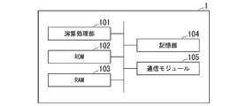
- FIG. 2 is a hardware configuration diagram of the control device according to the present embodiment.
- the control device 1 is a computer server provided with hardware such as an arithmetic processing unit 101, a ROM (Read Only Memory) 102, a RAM (Random Access Memory) 103, a storage unit 104, and a communication module 105.
- the arithmetic processing unit 101 is, for example, a CPU (Central Processing Unit), a GPU (Graphics Processing Unit), or the like.
- the storage unit 104 is, for example, an HDD (Hard Disk Drive), an SSD (Solid State Drive), a memory card, or the like. Further, the storage unit 104 may be a memory such as a RAM or a ROM.
- the communication module 105 transmits and receives data to and from an external device. For example, the communication module 105 communicates with an external device via a wired or wireless communication path.
- FIG. 3 is a functional block diagram of the control device according to the present embodiment.
- the control device 1 is activated when the power is turned on, and executes a control program stored in advance. As a result, the control device 1 exerts the functions of the image information acquisition unit 11, the distance information acquisition unit 12, the difference detection unit 13, the survey unit 14, the contact position identification unit 15, the transport control unit 16, and the display unit 17.
- the transported object 4 is an object to be transported, and an example is a cart or a trolley on which luggage is placed.
- the transport vehicle 3 transports the transported object 4 based on the control of the control device 1.
- the transport vehicle 3 receives information on the contact position indicating the position where the transport vehicle 3 contacts the transport object 4 from the control device 1, and conveys the transport object 4 by pushing or pulling the contact position.
- the side surface of the transported object 4 may or may not be included in the captured image depending on the positional relationship between the sensor 2 and the transported object 4. be.
- the conveyed object 4 is near the center of the measurement range of the sensor 2, the upper surface of the conveyed object 4 is reflected in the captured image, and the side surface is not reflected.
- the conveyed object 4 is located at a position away from the center of the measurement range of the sensor 2, the conveyed object 4 is photographed from diagonally above, so that the upper surface and the side surface of the conveyed object 4 are reflected in the photographed image.
- the control device 1 detects a region in the captured image in which the transported object 4 is projected using the captured image, the region may or may not include the side surface depending on the position of the transported object 4. do. Further, the closer the distance to the conveyed object 4 is to the sensor 2, the wider the upper surface area is reflected in the captured image. Therefore, even if the entire area of the transported object 4 displayed in the captured image differs depending on the height of the transported object 4 (distance from the sensor 2) and the positional relationship between the transported object 4 and the sensor 2, control is performed. The device needs to accurately calculate the contact position at a predetermined height at which the transport vehicle 3 can contact the transport object 4.
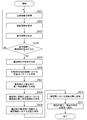
- FIG. 4 is a diagram showing a processing flow of the surveying system according to the present embodiment.
- the sensor 2 transmits a number of image information such as 30 frames per second to the control device 1. Further, the sensor 2 transmits a number of distance information such as 30 frames per second to the control device 1. It is assumed that the timings of the image information transmitted by the sensor 2 and the distance information match. The image information and the distance information indicate information in the same area.
- the image information acquisition unit 11 of the control device 1 acquires the image information (step S101).
- the distance information acquisition unit 12 of the control device 1 acquires the distance information (step S102).
- the image information acquisition unit 11 generates a background image based on the image information and records it in a storage unit such as a RAM 103.
- the generation and recording of the background image may be performed before detecting the conveyed object 4.
- the image information acquisition unit 11 may be performed when the surveying system 100 starts operating, or may be performed at the timing when the administrator of the surveying system 100 instructs the recording.
- the background image is image information when the transport vehicle 3, the transport object 4, and other foreign substances are not included in the measurement range.
- the image information acquisition unit 11 outputs the image information received from the sensor 2 to the difference detection unit 13.
- the distance information acquisition unit 12 records the distance information received from the sensor 2 in a storage unit such as the RAM 103.
- the image information acquisition unit 11 and the distance information acquisition unit 12 may each be assigned an ID or the like so that the relationship between the image information and the distance information corresponding to the transmission timing of the sensor 2 is linked.
- the difference detection unit 13 generates difference information indicating the difference between the image information received from the image information acquisition unit 11 and the background image. Specifically, when the difference detection unit 13 acquires the image information, the difference detection unit 13 compares the image information with the background image. The difference detection unit 13 generates difference information indicating a region in which a change occurs between the image information and the background image (step S103). For example, the difference detection unit 13 binarizes the image information and the background image into pixels indicating "0" and "1" based on the brightness of each pixel, and binarizes the binarized image information and the binarized image information. Generates difference information indicating the difference between each pixel and the background image. A pixel whose difference is "1" in this difference information indicates that some object is located in the measurement range. The difference detection unit 13 outputs the difference information to the surveying unit 14.
- the surveying unit 14 determines whether the acquired difference information includes the transported object 4 (step S104). For example, the surveying unit 14 determines whether the transport vehicle 3 is located in the measurement range, and if the difference information includes information other than the transport vehicle 3, it determines that the transport vehicle 4 is included.
- the position information of the transport vehicle 3 may be detected by the transport vehicle 3 and transmitted to the control device 1, or the measuring sensor 2 may detect the position of the transport vehicle 3 and transmit it to the control device 1.
- the measuring unit 14 determines whether or not the transport vehicle 3 is located in the measurement range by comparing the position information of the transport vehicle 3 with the position information of the measurement range measured by the sensor 2 stored in advance.
- the measuring unit 14 detects the position of the transport vehicle 3 from the image information by using the characteristics (brightness, size, etc.) of the transport vehicle 3 stored in advance, and identifies whether or not the vehicle 3 is located within the measurement range. You may.
- the method by which the measuring unit 14 detects the position of the transport vehicle 3 is not limited to the above.
- the surveying unit 14 may mask the region of the transport vehicle 3 in the measurement range indicated by the difference information to generate the difference information.
- the measuring unit 14 determines whether the transport vehicle 3 is located in the measurement range, and when the difference information acquired from the difference detection unit 13 includes information other than the transport vehicle 3, the transported object 4 is included.
- the specification of whether or not the transported object 4 is included is not limited to the above.
- the measuring unit 14 includes the transported object 4 in the difference information based on the information of the specified size of the transported object 4 even when the transported object 4 or the transport vehicle 3 is included in the measurement range. It may be determined whether or not.
- the surveying unit 14 identifies an inclusion area including the transported object 4. For example, the surveying unit 14 determines the size of a region of a group of pixels indicating that there is a difference in the difference information.
- the surveying unit 14 specifies that the outer frame of the area is the circumscribed frame R of the conveyed object 4 when the area of the group of pixels showing the difference of 1 in the difference information has a certain size or more (step S105). ).
- the circumscribed frame R indicates a frame of an inclusion region including the upper surface and the side surface of the conveyed object 4 to be measured.
- the method of specifying the outline frame R is not limited to the above method, and the surveying unit 14 may determine the circumscribed frame R of the region of the transported object 4 included in the difference information by another method.
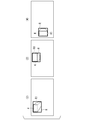
- FIG. 5 is a diagram showing a pattern of positions where the circumscribed frame R is detected in the measurement range.
- it is determined which of the first pattern and the third pattern the position pattern of the circumscribed frame R detected by the surveying unit 14 in the captured image is (step S106).
- the measurement range by the sensor 2 is divided into a vertical line 51 and a horizontal line 52 passing through the center of the measurement range, the upper right is the first region, the upper left is the second region, the lower left is the third region, and the lower right is the fourth region.
- FIG. 5 (1) shows the first pattern of the position of the circumscribed frame R.
- the first pattern is a pattern in which the four vertices of the circumscribed frame R are included in each of the first to fourth regions.
- the first pattern is a pattern that appears when the circumscribed frame R including the conveyed object 4 is located at the center.
- FIG. 5 (2) shows the second pattern of the position of the circumscribed frame R.
- the second pattern is a pattern in which all four vertices of the circumscribed frame R are included in one of the first to fourth regions.
- the second pattern is a pattern in which the circumscribed frame R including the conveyed object 4 appears only in any one of the first to fourth regions.
- FIGS. 5 (3) and 5 (4) show the third pattern of the position of the circumscribed frame R.
- the third pattern is a pattern in which the four vertices of the circumscribed frame R are located in the two regions, respectively.
- the third pattern shown in FIG. 5 (3) includes a case where the circumscribed frame R including the transported object 4 straddles the first region and the second region, and a case where the circumscribed frame R straddles the third region and the fourth region.
- the third pattern shown in FIG. 5 (4) includes a case where the circumscribed frame R including the transported object 4 straddles the second region and the third region, and a case where the circumscribed frame R straddles the first region and the fourth region.
- FIG. 6 is a diagram showing a photographing state of the transported object when the position of the circumscribed frame R is the first pattern.
- the position of the circumscribed frame R detected by the surveying unit 14 is the first pattern
- the upper surface of the conveyed object 4 is reflected in the captured image, and the side surface is not reflected in the captured image. Further, the closer the upper surface of the conveyed object 4 is to the sensor 2, the wider the area of the upper surface in the captured image.
- FIG. 7 is a diagram showing a photographing state of the transported object when the position of the circumscribed frame R is the second pattern or the third pattern.
- the position of the circumscribed frame R detected by the measuring unit 14 is the second pattern, as shown in FIG. 7 (2), the conveyed object 4 that can be connected to the upper surface of the conveyed object 4 and the position of the sensor 2 in a straight line. The surface is reflected in the captured image.
- the position of the circumscribed frame R detected by the surveying unit 14 is the third pattern, it is reflected in the captured image as shown in FIGS. 7 (3) and 7 (4).
- the surveying unit 14 first Judge as a pattern.
- the measuring unit 14 is one of four regions, the first region to the fourth region, in which all the coordinates of the pixels within the range of the circumscribed frame R are divided by a vertical line and a horizontal line passing through the center of the measurement range. If it is included only in, it is determined that it is the second pattern.
- the measuring unit 14 when the coordinates of the pixels within the range of the circumscribed frame R are located in two regions separated by a vertical line 51 passing through the center of the measurement range, or when the coordinates of the pixels within the range of the circumscribed frame R are determined. When it is located in two regions separated by a horizontal line 52 passing through the center of the measurement range, it is determined to be the third pattern.
- the surveying unit 14 specifies the first specific region R1 indicating the upper surface of the transported object 4 in the captured image (step S107). Specifically, the surveying unit 14 determines the relationship between the feature points appearing in the captured images of the plurality of circumscribed frames R specified in the circumscribed frame R and the height information of the feature points of the plurality of circumscribed frames R, and the circumscribed circle. Corresponding points appearing in captured images at predetermined heights that match the horizontal coordinates (horizontal position) of the feature points of the frame R and have different height coordinates, and the height information indicated by the predetermined height. Based on the relationship between, and, a plurality of corresponding points constituting the surface of the object at a predetermined height are calculated.
- the plurality of corresponding points constituting the surface of the object at a predetermined height include estimated corresponding points that do not appear in the captured image.
- the surveying unit 14 identifies the first specific region R1 indicating the upper surface of the transported object 4 in the captured image based on the plurality of corresponding points.
- the surveying unit 14 identifies the second specific region R2 that shows the region of the transported object 4 at the height at which the transport vehicle 3 contacts the transported object 4 in the photographed image (step S108).
- the contact position specifying unit 15 acquires the information of the second specific region R2 showing the region of the transported object 4 at the height h'when the transport vehicle 3 contacts the transported object 4 in the photographed image.
- the contact position specifying unit 15 acquires information on the feature points indicated by the second specific area R2.
- the contact position specifying unit 15 specifies a position in the captured image in which the transport vehicle 3 contacts the transported object 4 based on the information of the feature points indicated by the second specific region R2 (step S109).
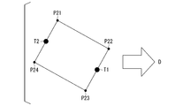
- FIG. 8 is a diagram showing a specific outline of the contact position.
- the contact position specifying unit 15 when the rectangle of the second specific area R2 indicates the feature points P21, P22, P23, P24, the transport vehicle 3 transports the center of any side of the second specific area R2. It is specified as the contact position T1 in the captured image in contact with the object 4.
- the contact position specifying unit 15 identifies the first side connecting the feature points P21 and P22 on the transport direction D side and the second side connecting the feature points P22 and P23, and among the normals of those sides.
- the center of the second side having a small angle with the transport direction D is designated as the contact position T1 in the photographed image in which the transport vehicle 3 contacts the transport object 4.
- the contact position specifying unit 15 outputs the contact position T1 to the transport control unit 16. For example, the transport vehicle 3 contacts the transport object 4 at the contact position T1 of the transport object 4 and pulls the transport object 4 in the transport direction D.
- the contact position specifying portion 15 is the side of the second specific region R2, which is on the opposite side of the transport direction D and has a normal line formed by a small angle with the transport direction. It may be specified as the contact position P in the captured image in contact with 4. That is, the contact position specifying portion 15 identifies a third side connecting the feature points P21 and P24 on the opposite side of the transport direction D and a fourth side connecting the feature points P24 and P23, and among the sides, The center of the third side having a normal having a small angle with the transport direction D is specified as the contact position T2 in the captured image in which the transport vehicle 3 contacts the transport object 4.
- the contact position specifying unit 15 outputs the contact position T2 to the transport control unit 16. In this case, the transport vehicle 3 comes into contact with the transport object 4 at the contact position of the transport object 4 and pushes the transport object 4 in the transport direction D.
- the transport control unit 16 converts the contact positions T1 and T2 in the captured image into the contact positions T1'and T2'in the real space (step S110). For example, the transport control unit 16 stores in advance the relationship between the coordinates in the virtual space indicated by the captured image and the coordinates in the real space, and based on the correspondence, the contact positions T1 and T2 are set to the contact positions in the real space. Convert to T1'and T2'.
- the transport control unit 16 transmits the contact positions T1'and T2'in the real space and the transport direction of the transport object 4 to the transport vehicle 3 (step S111).
- the transport vehicle 3 moves toward the contact positions T1'and T2', contacts the contact positions T1'and T2', and transports the transported object in the transport direction.
- the transported object 4 has been described by being transported by two transport vehicles 3, but a plurality of transport vehicles 3 are connected to the surveying system 100 by communication, and the transported objects 4 are transported by the plurality of transport vehicles 3.
- One transport vehicle may be connected to the surveying system 100 by communication, and one transport vehicle 3 may transport the transported object 4.
- the transported object 4 may be transported by contacting the transported object 4 from all sides with four transport vehicles 3, or one transport vehicle 3 may contact and tow any surface of the transported object 4.
- it may be conveyed by pushing it in.
- the transport control unit 16 transmits the contact position T1 to the first transport vehicle 3 and the contact position T3 to the second transport vehicle 3.
- the transport control unit 16 transmits the transport direction D to the first transport vehicle 3 and the second transport vehicle 3.
- the first transport vehicle 3 comes into contact with the contact position T1 of the transport object 4.
- the second transport vehicle 3 comes into contact with the contact position T2 of the transport object 4.
- the first transport vehicle 3 and the second transport vehicle 3 sandwich the transport object 4 with each other and transport the transport object 4 in the transport direction.
- the transport vehicle 3 comes into contact with the transport object 4, but the method of the transport vehicle 3 acting on the transport object 4 is not limited.
- the transport vehicle 3 may, for example, press the equipment of the transport vehicle against the transport object 4, connect or push (fit) the equipment into the dents or protrusions of the transport object 4, or apply an impact from the transport object 4. You may try to accept it.
- the transport vehicle 3 may grab the transport object 4 with an instrument that sandwiches the transport object 4 from two directions and tow it. For example, when the first transport vehicle 3 and the second transport vehicle 3 each come into contact with the transport object 4 to transport the transport object 4, the second transport vehicle 3 has the first force F1 at the contact position T2. And proceed in the direction of travel.
- the first transport vehicle 3 applies a second force F2 smaller than the first force F1 to the contact position T1 and advances in the same transport direction at the same speed as the first transport vehicle 3.
- the transported object 4 is transported by the second transport vehicle 3 of the first transport vehicle 3 and the second transport vehicle 3.
- the first transport vehicle 3 is connected to the contact position T1 and towed, and the second transport vehicle 3 applies a force to the contact position T2 to move in the transport direction while controlling the transported object 4 so as not to wobble.
- the second transport vehicle 3 is connected to the contact position T2 and pushes forward in the transport direction, and the first transport vehicle 3 applies a force to the contact position T1 to control the transport object 4 so as not to wobble in the transport direction. You may proceed.
- the position where the transport vehicle comes into contact with the transported object can be specified. Further, according to the processing of the surveying system described above, the transport vehicle can specify the contact position with the transported object with higher accuracy. Further, according to the processing of the surveying system 100 described above, the region of the transported object 4 reflected in the captured image is determined according to the height of the transported object 4 (distance from the sensor 2) and the positional relationship between the transported object 4 and the sensor 2. Even if they are different, the contact position at a predetermined height at which the transport vehicle 3 can contact the transport object 4 can be calculated with higher accuracy.
- FIG. 9 is a diagram showing an example of display information.
- the display unit 17 outputs the information specified by the control device 1 to a predetermined output destination.
- the display unit 17 acquires, for example, the circumscribed frame R, the first specific area R1, and the second specific area R2 from the photographed image to be processed and the surveying unit 14. Further, the display unit 17 acquires the contact position calculated based on the second specific area R2.
- the display unit 17 generates the captured image, the circumscribed frame R, the first specific area R1, the second specific area R2, the contact position information, and the display information to be displayed.
- the display unit 17 outputs display information to a predetermined output destination.
- the display unit 17 outputs display information to an LCD (Liquid Crystal Display), a CRT (Cathode Ray Tube) display, a monitor provided in the control device 1, and a terminal for communication connection to the control device 1.
- LCD Liquid Crystal Display
- CRT Cathode Ray Tube
- the display unit 17 may superimpose and display information on the circumscribed frame R, the first specific area R1, the second specific area R2, and the contact position as display information, or display each information separately.
- Display information may be generated such that arbitrary information selected by the worker involved in the work is superimposed and displayed.
- the processing of the surveying unit 14 for calculating the first specific area and the second specific area will be described in detail below.
- the measuring unit 14 determines that the circumscribed frame R is the upper surface of the conveyed object 4.
- the surveying unit 14 identifies a specific region (first specific region, second specific region) at a predetermined height of the transported object 4 included in the region of the external frame R based on the external frame R and its height information. ..
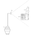
- FIG. 10 is a diagram showing an outline of calculation of the position of the transported object at a predetermined height.
- the focal length f when the sensor 2 captures image information an arbitrary feature point P1 on the upper surface of the transport object 4 in the real space, and the transport object whose coordinates X in the horizontal direction coincide with the feature point P1.
- the distance of the feature point P1 in the real space in the height direction from the sensor 2 is z
- the distance of the corresponding point P2 in the height direction from the sensor 2 is h
- the distance of the feature point P1 and the corresponding point P2 in the horizontal direction from the sensor 2 is Let X be the distance. In this case, it is based on the relationship between the height distance from the sensor 2 and the horizontal distance in the real space, and the relationship between the focal length in the captured image and the horizontal distance of each point from the center point of the captured image. Therefore, the following two equations (1) and (2) can be derived.
- Equations (3) and (4) are obtained as described above. Therefore,
- Equation (5) represented by The point x1 corresponding to the feature point P1 on the upper surface in the captured image, z in the real space, and the height h can be acquired by the sensor 2. Therefore, it is possible to calculate the point x2 in the captured image corresponding to an arbitrary corresponding point P2 in the real space by using the equation (5).
- the value of the height h may be measured by the sensor 2 at an arbitrary timing, or may be set as an initial value when the sensor 2 is installed, and the acquisition method thereof is not limited.
- "/" indicates division.
- ⁇ indicates multiplication.
- FIG. 11 is a diagram showing the relationship between the circumscribed frame R and the specific region in the first pattern.
- FIG. 11 (1) shows the transported object 4 shown in the captured image
- FIG. 11 (2) shows a perspective view of the corresponding transported object 4.
- the predetermined height h'of the transported object 4 is defined as the height at which the transport vehicle 3 comes into contact with the transported object 4.
- the height at which the transport vehicle 3 contacts the transported object 4 is a value known by the standard of the transport vehicle 3.
- the circumscribed frame R on the upper surface of the conveyed object 4 is specified in the photographed image.
- the circumscribed frame R specifies the circumscribed frame R as the first specific region R1.
- the first specific region R1 in the first pattern is a region presumed to indicate the upper surface of the transported object 4.
- the surveying unit 14 acquires a distance image corresponding to the captured image used to identify the circumscribed frame R of the transported object 4 from the storage unit or the like.
- the surveying unit 14 acquires the height information z (height information of the first specific region R1) of the feature points P11, P12, P13, and P14 of the circumscribed frame R in the distance image.
- the surveying unit 14 sets the position x1 of the feature points P11, P12, P13, and P14 specified in the circumscribed frame R in the equation (5), the height h'to h in the equation (5), and the height z to the equation (5).
- Z and the points x2 in the captured image corresponding to the corresponding points P21, P22, P23, and P24 constituting the region of the transported object 4 at the height h'are calculated.
- the surveying unit 14 identifies four vertices as feature points P11, P12, P13, and P14, and has a height h'corresponding to feature points P11, P12, P13, and P14.
- Corresponding points P21, P22, P23, P24 of are calculated using the equation (5).
- the heights of the feature points P11, P12, P13, and P14 are obtained from the distance information of each pixel of the circumscribed frame R.
- the heights of the corresponding points P21, P22, P23, and P24 are the heights h'where the predetermined transport vehicle 3 comes into contact with the transport object 4.
- the surveying unit 14 uses the region connecting the corresponding points P21, P22, P23, and P24 as the second specific region R2 showing the region of the transported object 4 at the height h'when the transport vehicle 3 contacts the transported object 4 in the photographed image. calculate.
- the surveying unit 14 identifies a plurality of feature points of the circumscribed frame R based on the circumscribed frame R having a shape other than a rectangle, and secondly identifies a region connecting the corresponding points corresponding to the plurality of feature points. It may be calculated as the region R2.
- the surveying unit 14 outputs the information of the second specific region R2 showing the region of the transported object 4 at the height h'where the transport vehicle 3 contacts the transported object 4 in the photographed image to the contact position specifying unit 15.
- the surveying unit 14 determines that the position of the circumscribed frame R of the transported object 4 is the second pattern, the circumscribed frame R includes the upper surface and the side surface of the transported object 4. Therefore, the surveying unit 14 specifies the first specific region R1 indicating the upper surface of the transported object 4 included in the region indicated by the circumscribed frame R as follows.
- FIG. 12 is a first diagram showing the relationship between the circumscribed frame R and the specific region in the second pattern.
- the surveying unit 14 specifies the position of the feature point in the circumscribed frame R by a predetermined method based on the shape of the circumscribed frame R and the pattern corresponding to the position of the circumscribed frame R. For example, when the circumscribed frame R is rectangular and the position of the circumscribed frame R is the second pattern, the four vertices P11, P12, P13, and P14 of the circumscribed frame R are specified as feature points.
- the surveying unit 14 has a distance h (the height of the feature point P13 in the real space and the sensor) indicating the height information of the feature point P13 closest to the center of the captured image among the feature points P11, P12, P13, and P14 specified in the external frame R.
- the distance from the height of 2) is acquired from the distance image, the background image, or the storage unit.
- the information in the height direction indicated by the pixels other than the region of the conveyed object 4 or the conveyed vehicle 3 in the distance image or the background image indicates the vertical distance between the height of the floor surface and the height of the sensor 2.
- the measuring unit 14 sets the distance z, which is the difference between the height of the feature point P11 farthest from the center of the captured image and the height of the sensor 2, among the feature points P11, P12, P13, and P14 specified in the circumscribed frame R. Is acquired from the distance image corresponding to the specified captured image.
- the distance z is also information indicating the height of each point on the upper surface of the conveyed object 4 including the points in the real space corresponding to the feature points P11.
- the surveying unit 14 sets the feature point P13 specified in the circumscribed frame R in the captured image as x2 of the equation (5), and sets the height information of the feature point P13 in the real space as h of the equation (5).
- the height information of the unknown corresponding point P23 on the upper surface corresponding to the horizontal position of the feature point P13 in the real space (corresponding to the information indicating the height of the feature point P11) is set to z in the equation (5), and the photograph is taken.
- the unknown corresponding point P23 (corresponding to x1 of the equation (5)) in the image is calculated.
- the surveying unit 14 sets the coordinates of the feature point P12 as x2 of the equation (5), sets the height information of the feature point P12 in the real space as h of the equation (5), and places the feature in the real space.
- the coordinates of the point P20 (corresponding to x1 of the equation (5)) of the height z corresponding to the horizontal position of the point P12 are obtained, and the line segment connecting P20 and P23 and the line segment connecting P11 and P12 are obtained.
- the coordinates of the point P22 are calculated as the intersection of the points.
- the remaining one point of the rectangle stretched by the points P11, P22, and P23 is obtained as the point P24.
- the surveying unit 14 includes a corresponding point P23 in a captured image indicating a point corresponding to the feature point P13 and a point on the upper surface corresponding to the horizontal position in the real space, and the external frame R connecting the feature points P12, P13, and P14.
- the intersections (P22, P24) connecting the straight line parallel to the side (the side connecting P12 and P13, the side connecting P13 and P14) and the circumscribing frame are specified as corresponding points.
- the surveying unit 14 identifies the rectangular region connecting the corresponding points 22, 23, 24 and the feature point P11 indicating the upper surface as the first specific region R1 presumed to indicate the upper surface of the conveyed object 4 in the second pattern. do.
- the surveying unit sets P11, P22, P23, and P24 as feature points (first corresponding points) of the first specific region R1.
- FIG. 13 is a second diagram showing the relationship between the external frame R and the specific region in the second pattern.
- the surveying unit 14 calculates the corresponding points P31, P32, P33, and P34 at the height h'where the transport vehicle 3 comes into contact with the transport object 4, and specifies the second specific region.
- the surveying unit 14 acquires a distance image corresponding to the captured image used for specifying the circumscribed frame R of the transported object 4 from the storage unit or the like.
- the surveying unit 14 acquires the height information z of the feature point P11 of the first specific region R1 in the distance image.
- the surveying unit 14 sets the position of the captured image corresponding to the feature point P11 specified in the first specific region R1 to x1 in the equation (5), and sets the height information of the feature point P11 indicating the upper surface of the transported object 4 as x1.
- the z of the formula (5) is set, the height h'of the transport vehicle 3 in contact with the transported object 4 is set to h of the formula (5), and they are input to the formula (5).
- the surveying unit 14 can calculate the position x2 in the captured image corresponding to the corresponding point P31 whose horizontal position corresponds to the feature point P11 in the real space.
- the surveying unit 14 similarly calculates the corresponding points P32, P33, and P34 of the height h'corresponding to the feature points P22, P23, and P24 when the transport vehicle 3 contacts the transported object 4, using the equation (5). do.
- the surveying unit 14 shows the region connecting the corresponding points P31, P32, P33, and P34 (second corresponding point) in the photographed image, and shows the region of the transported object 4 at the height h'when the transport vehicle 3 contacts the transported object 4.
- the surveying unit 14 identifies a plurality of feature points of the circumscribed frame R based on the circumscribed frame R having a shape other than a rectangle, and secondly identifies a region connecting the corresponding points corresponding to the plurality of feature points. It may be calculated as the region R2.
- the surveying unit 14 outputs the information of the second specific region R2 showing the region of the transported object 4 at the height h'where the transport vehicle 3 contacts the transported object 4 in the photographed image to the
- the surveying unit 14 determines that the position of the circumscribed frame R of the transported object 4 is the third pattern, the circumscribed frame R includes the upper surface and the side surface of the transported object 4. Therefore, the surveying unit 14 specifies the first specific region R1 indicating the upper surface of the transported object 4 included in the region indicated by the circumscribed frame R as follows.
- FIG. 14 is a first diagram showing the relationship between the circumscribed frame R and the specific region in the third pattern.
- the surveying unit 14 specifies the position of the feature point in the circumscribed frame R by a predetermined method based on the shape of the circumscribed frame R and the pattern corresponding to the position of the circumscribed frame R. For example, when the circumscribed frame R is rectangular and the position of the circumscribed frame R is the third pattern, the four vertices P11, P12, P13, and P14 of the circumscribed frame R are specified as feature points.
- the surveying unit 14 indicates a distance h (real space of the feature point P13 or P14) indicating the height information of the feature point P13 or P14 closest to the center of the captured image among the feature points P11, P12, P13, and P14 specified in the external frame R.
- the distance between the height of the sensor 2 and the height of the sensor 2) is acquired from a distance image, a background image, or a storage unit.
- the information in the height direction indicated by the pixels other than the region of the conveyed object 4 or the conveyed vehicle 3 in the distance image or the background image indicates the vertical distance between the height of the floor surface and the height of the sensor 2.
- the surveying unit 14 externally attaches a distance z, which is the difference between the height of the feature point P11 or P12 farthest from the center of the captured image and the height of the sensor 2, among the feature points P11, P12, P13, and P14 specified in the external frame R.
- the frame R is acquired from the distance image corresponding to the specified captured image.
- the distance z is also information indicating the height of each point on the upper surface of the conveyed object 4 including the points in the real space corresponding to the feature points P11 or P12.
- the surveying unit 14 sets the feature point P13 specified in the circumscribed frame R in the captured image as x2 of the equation (5), and sets the height information of the feature point P13 in the real space as h of the equation (5).
- the height information of the unknown corresponding point P23 on the upper surface corresponding to the horizontal position of the feature point P13 in the real space (corresponding to the information indicating the height of the feature point P11) is set to z in the equation (5), and the photograph is taken.
- the unknown corresponding point P23 (corresponding to x1 of the equation (5)) in the image is calculated.
- the surveying unit 14 sets the feature point P14 specified in the circumscribed frame R in the captured image as x2 of the equation (5), and sets the height information of the feature point P14 in the real space as h of the equation (5).
- the height information of the unknown corresponding point P24 on the upper surface corresponding to the horizontal position of the feature point P14 in the real space (corresponding to the information indicating the height of the feature point P11) is set to z in the equation (5).
- An unknown corresponding point P24 (corresponding to x1 of the equation (5)) in the captured image is calculated.
- the surveying unit 14 identifies the corresponding points P23'and P24' at which the straight lines of the corresponding points P23 and the corresponding points P24 intersect the circumscribed frame R as the corresponding points in the captured image corresponding to the points on the upper surface of the conveyed object 4.
- the surveying unit 14 defines a rectangular region connecting the corresponding points 23'and 24'and the feature points P11 and P12 indicating the upper surface as the first specific region R1 presumed to indicate the upper surface of the conveyed object 4 in the third pattern. To specify.
- the surveying unit sets P11, P12, P23', and P24'as feature points (first corresponding points) of the first specific region R1.
- the surveying unit 14 calculates the corresponding points P31, P32, P33, and P34 of the height h'where the transport vehicle 3 contacts the transported object 4, and the surveying unit 14 specifies the second specific area.
- a distance image corresponding to the captured image used to specify the frame R is acquired from the storage unit or the like.
- the surveying unit 14 acquires the height information z of the feature point P11 of the first specific region R1 in the distance image.
- the surveying unit 14 sets the position of the captured image corresponding to the feature point P11 specified in the first specific region R1 to x1 in the equation (5), and sets the height information of the feature point P11 indicating the upper surface of the transported object 4 as x1.
- the z of the formula (5) is set, the height h'of the transport vehicle 3 in contact with the transported object 4 is set to h of the formula (5), and they are input to the formula (5).
- the surveying unit 14 can calculate the position x2 in the captured image corresponding to the corresponding point P31 whose horizontal position corresponds to the feature point P11 in the real space.
- the surveying unit 14 similarly uses the equation (5) for the corresponding points P32, P33, and P34 of the height h'corresponding to the feature points P12, P23', and P24', in which the transport vehicle 3 contacts the transported object 4. To calculate.
- the surveying unit 14 shows the region connecting the corresponding points P31, P32, P33, and P34 (second corresponding point) in the photographed image, and shows the region of the transported object 4 at the height h'when the transport vehicle 3 contacts the transported object 4. Calculated as the second specific region R2.
- the surveying unit 14 identifies a plurality of feature points of the circumscribing frame R based on the circumscribing frame R having a shape other than the rectangular shape, and secondly identifies a region connecting the corresponding points corresponding to the plurality of feature points. It may be calculated as region R2.
- the surveying unit 14 outputs the information of the second specific region R2 showing the region of the transported object 4 at the height h'where the transport vehicle 3 contacts the transported object 4 in the photographed image to the contact position specifying unit 15.
- the surveying unit 14 determines that the position of the circumscribed frame R of the transported object 4 is the third pattern, the circumscribed frame R includes the upper surface and the side surface of the transported object 4. Therefore, the surveying unit 14 specifies the first specific region R1 indicating the upper surface of the transported object 4 included in the region indicated by the circumscribed frame R as follows.
- FIG. 15 is a second diagram showing the relationship between the circumscribed frame R and the specific region in the third pattern.
- the surveying unit 14 specifies the position of the feature point in the circumscribed frame R by a predetermined method based on the shape of the circumscribed frame R and the pattern corresponding to the position of the circumscribed frame R. For example, when the circumscribed frame R is rectangular and the position of the circumscribed frame R is the third pattern, the four vertices P11, P12, P13, and P14 of the circumscribed frame R are specified as feature points.
- the surveying unit 14 indicates a distance h (real space of the feature point P12 or P13) indicating the height information of the feature point P12 or P13 closest to the center of the captured image among the feature points P11, P12, P13, and P14 specified in the external frame R.
- the distance between the height of the sensor 2 and the height of the sensor 2) is acquired from a distance image, a background image, or a storage unit.
- the information in the height direction indicated by the pixels other than the region of the conveyed object 4 or the conveyed vehicle 3 in the distance image or the background image indicates the vertical distance between the height of the floor surface and the height of the sensor 2.
- the surveying unit 14 circumscribes the distance z, which is the difference between the height of the feature points P11 or P14 farthest from the center of the captured image and the height of the sensor 2 among the feature points P11, P12, P13, and P14 specified in the circumscribed frame R.
- the frame R is acquired from the distance image corresponding to the specified photographed image.
- the distance z is also information indicating the height of each point on the upper surface of the conveyed object 4 including the points in the real space corresponding to the feature points P11 or P14.
- the surveying unit 14 sets the feature point P12 specified in the circumscribed frame R in the captured image as x2 of the equation (5), and sets the height information of the feature point P12 in the real space as h of the equation (5).
- the height information of the unknown corresponding point P24 on the upper surface corresponding to the horizontal position of the feature point P14 in the real space (corresponding to the information indicating the height of the feature point P11) is set to z in the equation (5), and the photograph is taken.
- the unknown corresponding point P22 (corresponding to x1 of the equation (5)) in the image is calculated.
- the surveying unit 14 sets the feature point P13 specified in the circumscribed frame R in the captured image as x2 of the equation (5), and sets the height information of the feature point P13 in the real space as h of the equation (5).
- the height information of the unknown corresponding point P23 on the upper surface corresponding to the horizontal position of the feature point P13 in the real space (corresponding to the information indicating the height of the feature point P11) is set to z in the equation (5).
- An unknown corresponding point P23 (corresponding to x1 of the equation (5)) in the captured image is calculated.
- the surveying unit 14 identifies the corresponding points P22'and P23' at which the straight lines of the corresponding points P22 and the corresponding points P23 intersect the circumscribed frame R as the corresponding points in the captured image corresponding to the points on the upper surface of the conveyed object 4.
- the surveying unit 14 defines a rectangular region connecting the corresponding points P22'and P23'and the feature points P11 and P14 indicating the upper surface as the first specific region R1 presumed to indicate the upper surface of the conveyed object 4 in the third pattern. To specify.
- the surveying unit 14 sets P11, P22', P23', and P14 as feature points (first corresponding points) of the first specific region R1.
- the surveying unit 14 acquires a distance image corresponding to the captured image used to identify the circumscribed frame R of the transported object 4 from the storage unit or the like.
- the surveying unit 14 acquires the height information z of the feature point P11 of the first specific region R1 in the distance image.
- the surveying unit 14 sets the position of the captured image corresponding to the feature point P11 specified in the first specific region R1 to x1 in the equation (5), and sets the height information of the feature point P11 indicating the upper surface of the transported object 4 as x1.
- the z of the formula (5) is set, the height at which the transport vehicle 3 contacts the transported object 4 is set to h of the formula (5), and they are input to the formula (5).
- the surveying unit 14 can calculate the position x2 in the captured image corresponding to the corresponding point P31 whose horizontal position corresponds to the feature point P11 in the real space.
- the surveying unit 14 similarly uses the equation (5) for the corresponding points P32, P33, and P34 of the height h'corresponding to the feature points P22', P23', and P14, where the transport vehicle 3 contacts the transported object 4. To calculate.
- the surveying unit 14 shows the region connecting the corresponding points P31, P32, P33, and P34 (second corresponding point) in the photographed image, and shows the region of the transported object 4 at the height h'when the transport vehicle 3 contacts the transported object 4. Calculated as the second specific region R2.
- the surveying unit 14 identifies a plurality of feature points of the circumscribed frame R based on the circumscribed frame R having a shape other than a rectangle, and secondly identifies a region connecting the corresponding points corresponding to the plurality of feature points. It may be calculated as the region R2.
- the surveying unit 14 outputs the information of the second specific region R2 showing the region of the transported object 4 at the height h'where the transport vehicle 3 contacts the transported object 4 in the photographed image to the contact position specifying unit 15.
- the processing of the first specific region R1 of the surveying unit 14 in the second pattern and the third pattern described above is the relationship between the four feature points in the circumscribed frame R (object inclusion region) and the height information of the four feature points.
- the four first correspondence points at the height of the upper surface are calculated based on the above, and the first specification indicating the area of the object corresponding to the height of the upper surface of the specific regions based on the four first correspondence points. This is one aspect of the process of specifying the region.
- the horizontal coordinates of the first corresponding point at the height of the contact position of the object, which is the second predetermined height, and the coordinates of the height indicate the coordinates of the height of the contact position.
- four second corresponding points at the height of the contact position are calculated, and among the specific regions based on the four second corresponding points. It is one aspect of the process of specifying the second specific area indicating the area of the object corresponding to the height of the contact position of.
- the surveying system 100 specifies the contact position and the size of the transported object 4 to be surveyed at a predetermined height.
- the application of the surveying system 100 is not limited to this.
- FIG. 16 is a schematic configuration diagram of a control system including the control device according to the second embodiment.
- the conveyed object 4 is placed and moved on the belt conveyor 5 provided in the control system, and the control device included in the control system identifies the contact position with respect to the conveyed object 4, and the robot 6 provided in the control system.
- the control may be performed based on the contact position of the conveyed object 4.
- the control device 1 obtains the image information including the conveyed object 4 based on the change of the image information including the conveyed object 4 and the image information including the conveyed object 4.
- the circumscribed frame R object inclusion area indicating the area where the pixel information including the conveyed object 4 has changed is specified.
- the control device 1 identifies the circumscribed frame R of the conveyed object 4, the first specific area R1 (the area on the upper surface), and the second specific area R2 (the area at the height of the contact position).
- the contact position is specified based on the second specific area R2.
- the contact position of the conveyed object 4 of the robot 6 is such that the traveling direction of the belt conveyor 5 and the opposite sides formed by a small angle between the rectangular sides are opposed to each other. It may be specified, and the center of each of the two sides may be specified as the contact position.
- the control device 1 may control the robot 6 to grasp its contact position.
- the surveying system 100 may specify the occupancy rate of the luggage storage area and the size of the luggage from the area in the luggage storage area of the luggage to be surveyed.
- FIG. 17 is a diagram showing an example showing the arrangement relationship of luggage to be surveyed in the luggage storage area in another embodiment.
- the sensor 2 provided in the surveying system 100 captures a photographed image of the luggage 162 in the luggage storage area 161 from above to below.
- the control device 1 provided in the surveying system 100 sets the circumscribed frame R, the first specific area R1 (upper surface area), and the second specific area R2 (area of a predetermined height) of each package detected based on the captured image. , As with the other embodiments described above.
- the control device 1 may calculate the second specific area R2 of the luggage 162 detected based on the photographed image and the space (empty space 163 or aisle space 164) in the luggage storage area 161 in the photographed image. In this case, the control device 1 stores the area of the luggage storage area in advance, and identifies the area where the second specific area R2 at a predetermined height of the luggage 162 is not detected. The control device 1 may specify an area in which the second specific area R2 is not detected as an empty space 163 or a passage space 164. Further, the surveying system 100 specifies the size of the object and the size of the passage through which the object passes, determines whether or not the passage is possible, extracts the passable route, and determines the transport route to the transport location. You may. The surveying system 100 may allow a worker or a site manager to remotely grasp the size of an object or specify the size of a load flowing on a belt conveyor.
- FIG. 18 is a schematic configuration of a surveying system according to a third embodiment.
- the surveying system 100 includes a control device 1, a sensor 2, and a transported object 4.
- the control device 1 is connected so as to be able to communicate via a network.
- FIG. 18 is a schematic configuration diagram of the control device 1 according to the third embodiment.
- the control device 1 is an information processing device such as a computer.
- FIG. 19 is a functional block diagram of the control device according to the third embodiment.
- the control device 1 may be realized by cloud computing.
- the control device 1 includes a difference detection unit 13 and a surveying unit 14.
- the difference detection unit 13 has the first image information to the second image based on the first image information that does not include the object in the photographable area and the second image information that includes the object in the photographable area. Detect areas where changes have occurred in information.
- the surveying unit 14 identifies the object inclusion area indicating the area where the change has occurred, and specifies the two-dimensional size of the object included in the object inclusion area based on the object inclusion area and the height information.
- FIG. 20 is a diagram showing a processing flow by the control device according to the third embodiment.
- the control device 1 that communicates and connects to the sensor that acquires the height information of the object and the image information of the object includes at least a difference detection unit 13 and a surveying unit 14.
- the difference detection unit 13 detects a region in which the pixel information including the object has changed in the image information including the object based on the change in the image information not including the object and the image information including the object (step S181). ).
- the surveying unit 14 specifies the two-dimensional size of the object included in the object inclusion area based on the object inclusion area indicating the area where the image information has changed and the predetermined height information (step S182).
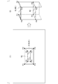
- FIG. 21 is a diagram showing an outline of processing of the control device according to the third embodiment.
- the surveying unit 14 specifies the two-dimensional size of the upper surface of the transported object 4, the feature points (P12, P13, P14) and the features in the object inclusion area (R) including the entire area of the object reflected in the image information.
- the relationship of the height information of the points (P12, P13, P14) is detected.
- the height information of P12, P13, and P14 is clear from the distance information output by the sensor 2.
- the surveying unit 14 defines the corresponding points (P22, P23, P24) at a predetermined height (for example, the height of the upper surface) corresponding to the feature points (P12, P13, P14) and the horizontal position (horizontal coordinates). Detects the relationship with the height information indicated by the height (height of the upper surface). The height information of the upper surface is clear from the distance information of P11 output by the sensor 2. The surveying unit 14 calculates corresponding points (P11, P22, P23, P24) at the height of the upper surface based on these relationships. The surveying unit 14 identifies the region including these P11, P12, P23, and P24 as a specific region (first specific region) indicating the size of the upper surface. The first specific region is an example of a region indicating the two-dimensional size of an object.
- the first specific region is an example of a region indicating the two-dimensional size of an object.
- the measuring unit 14 specifies the two-dimensional size of the contact position of the transported object 4, the feature points (P11, P22, P23, P24) of the specific region (first specific region) indicating the size of the upper surface and the feature points.
- the relationship of the height information of (P11, P22, P23, P24) is detected.
- the height information of P11, P22, P23, and P24 is clear from the distance information output by the sensor 2.
- the surveying unit 14 is at a predetermined height (for example, the height of the contact position where the transport vehicle contacts the transported object) corresponding to the feature points (P11, P22, P23, P24) and the horizontal position (horizontal coordinates).
- the relationship between the corresponding points (P31, 32, 33, 34) and the height information indicated by the predetermined height (height of the contact position) is detected.
- the height information of the contact position is predetermined.
- the surveying unit 14 calculates the corresponding points (P31, 32, 33, 34) at the height of the contact position based on these relationships.
- the surveying unit 14 identifies the region including these P31, 32, 33, 34 as a specific region (second specific region) indicating the size of the upper surface.
- the second specific region is also an example of a region showing the two-dimensional size of the object.
- the above-mentioned control device 1 has a computer system inside.
- the process of each process described above is stored in a computer-readable recording medium in the form of a program, and the process is performed by the computer reading and executing this program.
- the computer-readable recording medium refers to a magnetic disk, a magneto-optical disk, a CD-ROM, a DVD-ROM, a semiconductor memory, or the like.
- this computer program may be distributed to a computer via a communication line, and the computer receiving the distribution may execute the program.
- the above program may be for realizing a part of the above-mentioned functions.
- a so-called difference file difference program
- difference program difference program
Landscapes
- Engineering & Computer Science (AREA)
- Physics & Mathematics (AREA)
- General Physics & Mathematics (AREA)
- Theoretical Computer Science (AREA)
- Multimedia (AREA)
- Computer Vision & Pattern Recognition (AREA)
- Automation & Control Theory (AREA)
- Remote Sensing (AREA)
- Radar, Positioning & Navigation (AREA)
- Aviation & Aerospace Engineering (AREA)
- Geometry (AREA)
- Electromagnetism (AREA)
- Length Measuring Devices By Optical Means (AREA)
- Image Analysis (AREA)
- Image Processing (AREA)
Priority Applications (3)
| Application Number | Priority Date | Filing Date | Title |
|---|---|---|---|
| US17/801,996 US12444070B2 (en) | 2020-02-28 | 2020-02-28 | Measuring method, measuring apparatus, and measuring system |
| JP2022503049A JP7364033B2 (ja) | 2020-02-28 | 2020-02-28 | 測量方法、測量装置、測量システム、プログラム |
| PCT/JP2020/008506 WO2021171610A1 (ja) | 2020-02-28 | 2020-02-28 | 測量方法、測量装置、測量システム |
Applications Claiming Priority (1)
| Application Number | Priority Date | Filing Date | Title |
|---|---|---|---|
| PCT/JP2020/008506 WO2021171610A1 (ja) | 2020-02-28 | 2020-02-28 | 測量方法、測量装置、測量システム |
Publications (1)
| Publication Number | Publication Date |
|---|---|
| WO2021171610A1 true WO2021171610A1 (ja) | 2021-09-02 |
Family
ID=77490410
Family Applications (1)
| Application Number | Title | Priority Date | Filing Date |
|---|---|---|---|
| PCT/JP2020/008506 Ceased WO2021171610A1 (ja) | 2020-02-28 | 2020-02-28 | 測量方法、測量装置、測量システム |
Country Status (3)
| Country | Link |
|---|---|
| US (1) | US12444070B2 (https=) |
| JP (1) | JP7364033B2 (https=) |
| WO (1) | WO2021171610A1 (https=) |
Citations (4)
| Publication number | Priority date | Publication date | Assignee | Title |
|---|---|---|---|---|
| JPH05240446A (ja) * | 1992-02-26 | 1993-09-17 | Toshiba Corp | 加熱調理装置 |
| JPH0826611A (ja) * | 1994-07-08 | 1996-01-30 | Hitachi Ltd | エレベーターのかご内物体検出装置 |
| JP2017010535A (ja) * | 2015-06-25 | 2017-01-12 | 東芝テック株式会社 | 物品認識装置および画像処理方法 |
| JP2019020307A (ja) * | 2017-07-20 | 2019-02-07 | キヤノン株式会社 | 計測装置、計測装置の制御方法およびプログラム |
Family Cites Families (13)
| Publication number | Priority date | Publication date | Assignee | Title |
|---|---|---|---|---|
| JP4470067B2 (ja) * | 2007-08-07 | 2010-06-02 | 本田技研工業株式会社 | 対象物種別判定装置、車両 |
| EP2827318A4 (en) * | 2012-03-12 | 2016-01-13 | Honda Motor Co Ltd | DEVICE FOR MONITORING A VEHICLE ENVIRONMENT |
| US8972061B2 (en) * | 2012-11-02 | 2015-03-03 | Irobot Corporation | Autonomous coverage robot |
| JP6090786B2 (ja) * | 2013-05-09 | 2017-03-08 | 国立大学法人 東京大学 | 背景差分抽出装置及び背景差分抽出方法 |
| WO2014200257A1 (en) * | 2013-06-11 | 2014-12-18 | Samsung Electronics Co., Ltd. | Method and apparatus for obtaining x-ray image of region of interest of object |
| JP6307626B2 (ja) * | 2014-10-21 | 2018-04-04 | オリンパス株式会社 | 操作装置、操作装置を備える情報処理装置、及び情報処理装置のための操作受付方法 |
| JP6752615B2 (ja) * | 2015-07-29 | 2020-09-09 | キヤノン株式会社 | 情報処理装置、情報処理方法、ロボット制御装置及びロボットシステム |
| CN118605029A (zh) * | 2016-01-19 | 2024-09-06 | 奇跃公司 | 利用映像的增强现实系统和方法 |
| JP2017211691A (ja) | 2016-05-23 | 2017-11-30 | 株式会社ツクタ技研 | 画像処理装置、画像処理方法、および画像処理プログラム |
| US10290136B2 (en) * | 2016-08-10 | 2019-05-14 | Zeekit Online Shopping Ltd | Processing user selectable product images and facilitating visualization-assisted coordinated product transactions |
| JP2018092354A (ja) * | 2016-12-02 | 2018-06-14 | 富士通株式会社 | 物体検出装置および物体検出方法 |
| JP2019126875A (ja) * | 2018-01-24 | 2019-08-01 | 株式会社イシダ | 物品移載装置 |
| JP7171294B2 (ja) * | 2018-07-31 | 2022-11-15 | キヤノン株式会社 | 情報処理装置、情報処理方法及びプログラム |
-
2020
- 2020-02-28 US US17/801,996 patent/US12444070B2/en active Active
- 2020-02-28 WO PCT/JP2020/008506 patent/WO2021171610A1/ja not_active Ceased
- 2020-02-28 JP JP2022503049A patent/JP7364033B2/ja active Active
Patent Citations (4)
| Publication number | Priority date | Publication date | Assignee | Title |
|---|---|---|---|---|
| JPH05240446A (ja) * | 1992-02-26 | 1993-09-17 | Toshiba Corp | 加熱調理装置 |
| JPH0826611A (ja) * | 1994-07-08 | 1996-01-30 | Hitachi Ltd | エレベーターのかご内物体検出装置 |
| JP2017010535A (ja) * | 2015-06-25 | 2017-01-12 | 東芝テック株式会社 | 物品認識装置および画像処理方法 |
| JP2019020307A (ja) * | 2017-07-20 | 2019-02-07 | キヤノン株式会社 | 計測装置、計測装置の制御方法およびプログラム |
Also Published As
| Publication number | Publication date |
|---|---|
| JPWO2021171610A1 (https=) | 2021-09-02 |
| JP7364033B2 (ja) | 2023-10-18 |
| US12444070B2 (en) | 2025-10-14 |
| US20230087312A1 (en) | 2023-03-23 |
Similar Documents
| Publication | Publication Date | Title |
|---|---|---|
| JP6649796B2 (ja) | 物体状態特定方法、物体状態特定装置、および、搬送車 | |
| JP7548401B2 (ja) | 搬送システム、搬送制御装置、搬送方法 | |
| US20190311497A1 (en) | Methods and computer program products for calibrating stereo imaging systems by using a planar mirror | |
| JP6646854B2 (ja) | 投影指示装置、荷物仕分けシステムおよび投影指示方法 | |
| CN101685001A (zh) | 侦测方法及侦测系统 | |
| JP6590153B2 (ja) | 投影指示装置、荷物仕分けシステムおよび投影指示方法 | |
| JP6646853B2 (ja) | 投影指示装置、荷物仕分けシステムおよび投影指示方法 | |
| US20190042847A1 (en) | Instruction projecting device, package sorting system and instruction projecting method | |
| WO2019130931A1 (ja) | 測位装置及び車両 | |
| JP2024084756A (ja) | 車両監視方法、車両監視装置、車両、及び車両監視システム | |
| JP7364033B2 (ja) | 測量方法、測量装置、測量システム、プログラム | |
| JP2003075148A (ja) | デジタルスチルカメラを用いた変位計測装置 | |
| JP6628039B2 (ja) | 投影指示装置、荷物仕分けシステムおよび投影指示方法 | |
| JP3055721B2 (ja) | 左,右カメラの撮像画像の対応点検索方法 | |
| JP6628038B2 (ja) | 投影指示装置、荷物仕分けシステムおよび投影指示方法 | |
| WO2024190314A1 (ja) | 制御システム、制御装置、制御方法及びプログラム | |
| JP2002236991A (ja) | Etcシステムの単一車輌性の判定装置、及び、その判定方法 |
Legal Events
| Date | Code | Title | Description |
|---|---|---|---|
| 121 | Ep: the epo has been informed by wipo that ep was designated in this application |
Ref document number: 20921649 Country of ref document: EP Kind code of ref document: A1 |
|
| ENP | Entry into the national phase |
Ref document number: 2022503049 Country of ref document: JP Kind code of ref document: A |
|
| NENP | Non-entry into the national phase |
Ref country code: DE |
|
| 122 | Ep: pct application non-entry in european phase |
Ref document number: 20921649 Country of ref document: EP Kind code of ref document: A1 |
|
| WWG | Wipo information: grant in national office |
Ref document number: 17801996 Country of ref document: US |