WO2021171586A1 - 画像取得装置、画像取得方法および画像処理装置 - Google Patents
画像取得装置、画像取得方法および画像処理装置 Download PDFInfo
- Publication number
- WO2021171586A1 WO2021171586A1 PCT/JP2020/008421 JP2020008421W WO2021171586A1 WO 2021171586 A1 WO2021171586 A1 WO 2021171586A1 JP 2020008421 W JP2020008421 W JP 2020008421W WO 2021171586 A1 WO2021171586 A1 WO 2021171586A1
- Authority
- WO
- WIPO (PCT)
- Prior art keywords
- voltage
- image
- information
- imaging means
- image acquisition
- Prior art date
- Legal status (The legal status is an assumption and is not a legal conclusion. Google has not performed a legal analysis and makes no representation as to the accuracy of the status listed.)
- Ceased
Links
Images


Classifications
-
- H—ELECTRICITY
- H04—ELECTRIC COMMUNICATION TECHNIQUE
- H04N—PICTORIAL COMMUNICATION, e.g. TELEVISION
- H04N23/00—Cameras or camera modules comprising electronic image sensors; Control thereof
- H04N23/60—Control of cameras or camera modules
- H04N23/67—Focus control based on electronic image sensor signals
-
- G—PHYSICS
- G06—COMPUTING OR CALCULATING; COUNTING
- G06V—IMAGE OR VIDEO RECOGNITION OR UNDERSTANDING
- G06V40/00—Recognition of biometric, human-related or animal-related patterns in image or video data
- G06V40/10—Human or animal bodies, e.g. vehicle occupants or pedestrians; Body parts, e.g. hands
- G06V40/18—Eye characteristics, e.g. of the iris
- G06V40/19—Sensors therefor
-
- G—PHYSICS
- G02—OPTICS
- G02B—OPTICAL ELEMENTS, SYSTEMS OR APPARATUS
- G02B7/00—Mountings, adjusting means, or light-tight connections, for optical elements
- G02B7/02—Mountings, adjusting means, or light-tight connections, for optical elements for lenses
- G02B7/04—Mountings, adjusting means, or light-tight connections, for optical elements for lenses with mechanism for focusing or varying magnification
-
- G—PHYSICS
- G02—OPTICS
- G02B—OPTICAL ELEMENTS, SYSTEMS OR APPARATUS
- G02B7/00—Mountings, adjusting means, or light-tight connections, for optical elements
- G02B7/02—Mountings, adjusting means, or light-tight connections, for optical elements for lenses
- G02B7/04—Mountings, adjusting means, or light-tight connections, for optical elements for lenses with mechanism for focusing or varying magnification
- G02B7/08—Mountings, adjusting means, or light-tight connections, for optical elements for lenses with mechanism for focusing or varying magnification adapted to co-operate with a remote control mechanism
-
- G—PHYSICS
- G02—OPTICS
- G02B—OPTICAL ELEMENTS, SYSTEMS OR APPARATUS
- G02B7/00—Mountings, adjusting means, or light-tight connections, for optical elements
- G02B7/02—Mountings, adjusting means, or light-tight connections, for optical elements for lenses
- G02B7/04—Mountings, adjusting means, or light-tight connections, for optical elements for lenses with mechanism for focusing or varying magnification
- G02B7/09—Mountings, adjusting means, or light-tight connections, for optical elements for lenses with mechanism for focusing or varying magnification adapted for automatic focusing or varying magnification
-
- G—PHYSICS
- G02—OPTICS
- G02B—OPTICAL ELEMENTS, SYSTEMS OR APPARATUS
- G02B7/00—Mountings, adjusting means, or light-tight connections, for optical elements
- G02B7/28—Systems for automatic generation of focusing signals
- G02B7/36—Systems for automatic generation of focusing signals using image sharpness techniques, e.g. image processing techniques for generating autofocus signals
-
- G—PHYSICS
- G03—PHOTOGRAPHY; CINEMATOGRAPHY; ANALOGOUS TECHNIQUES USING WAVES OTHER THAN OPTICAL WAVES; ELECTROGRAPHY; HOLOGRAPHY
- G03B—APPARATUS OR ARRANGEMENTS FOR TAKING PHOTOGRAPHS OR FOR PROJECTING OR VIEWING THEM; APPARATUS OR ARRANGEMENTS EMPLOYING ANALOGOUS TECHNIQUES USING WAVES OTHER THAN OPTICAL WAVES; ACCESSORIES THEREFOR
- G03B13/00—Viewfinders; Focusing aids for cameras; Means for focusing for cameras; Autofocus systems for cameras
- G03B13/32—Means for focusing
- G03B13/34—Power focusing
- G03B13/36—Autofocus systems
-
- G—PHYSICS
- G06—COMPUTING OR CALCULATING; COUNTING
- G06V—IMAGE OR VIDEO RECOGNITION OR UNDERSTANDING
- G06V40/00—Recognition of biometric, human-related or animal-related patterns in image or video data
- G06V40/10—Human or animal bodies, e.g. vehicle occupants or pedestrians; Body parts, e.g. hands
- G06V40/18—Eye characteristics, e.g. of the iris
- G06V40/193—Preprocessing; Feature extraction
-
- H—ELECTRICITY
- H04—ELECTRIC COMMUNICATION TECHNIQUE
- H04N—PICTORIAL COMMUNICATION, e.g. TELEVISION
- H04N23/00—Cameras or camera modules comprising electronic image sensors; Control thereof
- H04N23/45—Cameras or camera modules comprising electronic image sensors; Control thereof for generating image signals from two or more image sensors being of different type or operating in different modes, e.g. with a CMOS sensor for moving images in combination with a charge-coupled device [CCD] for still images
-
- H—ELECTRICITY
- H04—ELECTRIC COMMUNICATION TECHNIQUE
- H04N—PICTORIAL COMMUNICATION, e.g. TELEVISION
- H04N23/00—Cameras or camera modules comprising electronic image sensors; Control thereof
- H04N23/90—Arrangement of cameras or camera modules, e.g. multiple cameras in TV studios or sports stadiums
Definitions
- the present invention relates to an image acquisition device, an image acquisition method, and an image processing device that are suitably applied to iris recognition.
- Biometric authentication using iris that is, iris authentication is known.
- iris recognition the iris of the person to be authenticated is photographed using an imaging device, and a feature amount is extracted from the photographed iris pattern.
- the extracted feature amount and the feature amount registered in the database in advance are collated, and pass / fail is determined based on the collation score.
- the extracted features are registered in the database.
- a device When performing iris recognition, if the distance between the subject's iris (that is, the subject) and the camera changes while the subject is being photographed, it will not be possible to capture an image that is in focus. There is a risk.
- a device has been proposed in which the lens of the camera is moved in the optical axis direction so as to focus on each of a plurality of predetermined positions, and an image is taken at each position (for example,). See Patent Document 1). After taking a plurality of images, the device selects one image that is presumed to be in focus from the plurality of images. Then, the device performs iris recognition using the selected image.
- Patent Document 2 describes a device that performs image processing using a liquid lens.
- the device described in Patent Document 1 does not start iris recognition until a plurality of images have been captured, even if the first image captured is a focused image. Further, in the in-focus image, if a part of the iris of the subject is hidden due to blinking of the eyes or the like, the iris authentication is not executed correctly. In that case, the device will redo the acquisition of a plurality of images. Therefore, when the device described in Patent Document 1 is used, there is a problem that iris recognition takes time.
- the image acquisition device can specify the voltage applied to the first variable focus lens included in the first imaging means installed at a position where a subject can be photographed and whose focal distance changes according to the applied voltage.
- the voltage applied to the second variable focus lens which is included in the second imaging means installed at a position where the subject can be photographed and whose focal distance changes according to the applied voltage, can be specified by generating the first voltage information.
- the voltage control means generates information that can identify each voltage in the time-series voltage whose value changes with the passage of time as the first voltage information, and uses the first voltage information as the second voltage information. Generates identifiable information that each identified voltage is applied to the second variable focus lens with a delay of a predetermined period.
- the image acquisition method can specify the voltage applied to the first variable focus lens included in the first imaging means installed at a position where the subject can be photographed and whose focal distance changes according to the applied voltage.
- the voltage applied to the second variable focus lens which is included in the second imaging means installed at a position where the subject can be photographed and whose focal distance changes according to the applied voltage, can be specified by generating the first voltage information.
- the second voltage information is generated, the first voltage information is information that can specify each voltage in the time-series voltage whose value changes with the passage of time, and the second voltage information is the first voltage information. It is information that can identify that each specified voltage is applied to the second variable focus lens with a delay of a predetermined period, and is captured at the in-focus position from the images input from the first imaging means and the second imaging means. Select the only image.
- the image acquisition program applies a voltage applied to a first variable focus lens, which is included in a first imaging means installed at a position where a subject can be photographed and whose focal distance changes according to the applied voltage, to a computer.
- the voltage applied to the second variable focus lens that generates identifiable first voltage information and is included in the second imaging means installed at a position where the subject can be photographed and whose focal distance changes according to the applied voltage.
- a process for generating identifiable second voltage information is executed, and the first voltage information is information that can specify each voltage in a time-series voltage whose value changes with the passage of time, and is the second voltage information.
- the present invention it is possible to shorten the time until an image used for image processing such as iris recognition is obtained. In addition, it is possible to shorten the time until the process of acquiring an image suitable for image processing is completed.
- FIG. 1 is an explanatory diagram showing an outline of control of the image acquisition device of the embodiment.
- the imaging unit (camera) 200 facing the authentication target person 50 is installed so that the eye area (area including the iris) including both eyes of the target person 50 can be photographed.
- the imaging unit 200 changes the focal length within a predetermined focal movement range. That is, the imaging unit 200 changes the focal position.
- the focal movement range is a range in which at least the iris of the subject 50 matches the focal position while the imaging unit 200 is moving.
- FIG. 1B shows how a single imaging unit 200 (specifically, a camera lens) changes the focal length.
- FIG. 1C shows how the two imaging units 200 change the focal length.
- the change in the focal position shown in FIG. 1 (C) corresponds to the change in the following embodiment. That is, the image acquisition device of the embodiment controls the focal lengths of the two imaging units 200.
- "front" indicates the end closest to the imaging unit 200 in the focal movement range.
- “Rear” indicates the end farthest from the imaging unit 200 in the focal movement range.
- a liquid lens that changes the lens power (the reciprocal of the focal length) according to the applied voltage is used as the lens of the imaging unit 200. That is, the focal length of the liquid lens changes when the applied voltage changes.
- the focal length is controlled so that the focal length of the imaging unit 200 gradually changes from the "front” position to the "rear” position and then gradually changes from the “rear” position to the "front” position. That is, the case where the focal length reciprocates is assumed.
- the "time to return” indicates the time for the focal position to make one round trip starting from the position P.
- the focal position is shown to change linearly, but in the embodiment, the value of the voltage sequentially applied to the imaging unit 200 changes stepwise. .. Therefore, in reality, the change in the focal position is stepwise.
- a single imaging unit 200 changes the focal length stepwise, and each time the focal length changes, the imaging unit 200 takes the subject 50 (specifically, the eye region). Take a picture.
- focusing means that the focal position P matches the position of the iris of the subject 50. Therefore, image processing (image analysis) such as iris recognition is executed using the image taken at the “focus” position.
- image processing image analysis
- iris recognition is executed using the image taken at the “focus” position.
- the image taken at the "focus” position is referred to as an in-focus image.
- iris recognition or the like cannot be executed based on the image.
- FIG. 1 (B) when an in-focus image is obtained when the eyelids with the subject are closed, the focal position is one from that point in time, that is, the first in-focus point. The in-focus image must be acquired again after going back and forth. Therefore, it takes time to complete the iris recognition and the like.
- the other imaging unit 200 changes the focal position with a delay with respect to the change in the focal position of one imaging unit 200.
- T indicates a delay time (delay time) of a change in the focal position of the other imaging unit 200.
- the delay time T is set to a time similar to the time required for blinking of a general subject 50. Since the time required for blinking of a general subject 50 is 150 to 250 ms, the delay time T can be selected from the time interval (with a margin, for example, from 100 to 300 ms). preferable. As an example, the delay time T is set to 200 ms.
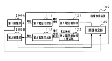
- FIG. 2 is a block diagram showing a configuration example of the image acquisition device together with the imaging unit.
- the image acquisition device 100 shown in FIG. 2 controls the first imaging unit 200A and the second imaging unit 200B, and inputs the images captured by the first imaging unit 200A and the second imaging unit 200B.
- the image acquisition device 100 includes a first voltage application unit 111, a second voltage application unit 112, a first voltage control unit 121, a second voltage control unit (delay unit) 122, and an image determination unit 130.
- each of the first imaging unit 200A and the second imaging unit 200B is installed at a position where the subject's face (at least the area including both eyes) can be photographed.
- each of the first imaging unit 200A and the second imaging unit 200B includes a liquid lens whose focal length is determined according to the applied voltage.
- a varifocal lens other than a liquid lens may be used as long as the lens has a focal length that changes electrically.
- the first voltage control unit 121 creates voltage information from the control information (control data) input from the image determination unit 130.
- the first voltage control unit 121 outputs voltage information to the first voltage application unit 111 and the second voltage control unit 122.
- the voltage information output by the first voltage control unit 121 corresponds to the first voltage information.
- the control data includes, for example, a trigger for starting voltage control and information indicating that an image has been captured from the first imaging unit 200A.
- the control data corresponds to data indicating the switching timing of the voltage value applied to the liquid lens in the first imaging unit 200A.
- the first voltage information is information that allows the first voltage control unit 121 to specify the voltage value applied to the liquid lens in the first imaging unit 200A.
- the first voltage information is information indicating the voltage value itself such as 3V.
- the pattern of the voltage that changes in time series for example, 0.5V changes every 16ms between 0 and 30V
- the first voltage information simply indicates the switching time of the voltage value. It may be information.
- the second voltage control unit 122 generates voltage information based on the first voltage information and outputs the voltage information to the second voltage application unit 112.
- the voltage information output by the second voltage control unit 122 corresponds to the second voltage information.
- the second voltage control unit 122 outputs the first voltage information as the second voltage information to the second voltage application unit 112 when the delay time T elapses from the time when the first voltage information is input.
- the first voltage application unit 111 applies a voltage of a value specified by the first voltage information to the liquid lens in the first imaging unit 200A.
- the second voltage application unit 112 applies a voltage having a value specified by the second voltage information to the liquid lens in the second imaging unit 200B.
- the image determination unit 130 inputs images taken by each of the first imaging unit 200A and the second imaging unit 200B.
- the image input cycle is preferably about the same as the switching cycle of the voltage value applied to the liquid lens.
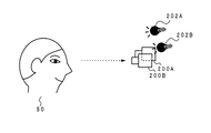
- FIG. 3 is an explanatory view showing an arrangement example of the first imaging unit 200A and the second imaging unit 200B.
- the position where the iris authentication target person 50 should exist is a predetermined predetermined position.
- the first imaging unit 200A and the second imaging unit 200B are installed at positions where an iris image (an image of a small area including an iris) of the subject 50 at a predetermined position can be captured.
- a plurality of pairs consisting of the first imaging unit 200A and the second imaging unit 200B may be installed at positions having different heights from the ground or the floor surface. ..
- one pair matching the height of the subject 50 is used for the authentication process.
- a wide-range imaging camera (overall view camera) capable of capturing the entire body of people of various heights is installed, and an iris image of the subject 50 can be captured based on a wide-range image supplied from the wide-range imaging camera.
- a pair consisting of the first imaging unit 200A and the second imaging unit 200B is selected.
- Lighting devices 202A and 202B for irradiating the subject 50 with light are also installed.
- the lighting devices 202A and 202B include a light source (for example, LED: Light Emitting Diode).
- the lighting devices 202A and 202B may be controlled to irradiate light during the period from the start to the end of image input from the first imaging unit 200A and the second imaging unit 200B, or may be in a state of constantly irradiating light. It may be controlled so as to be. Further, the first imaging unit 200A and the second imaging unit 200B may be turned on only at the timing of shooting.
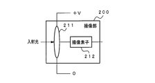
- FIG. 4 is a block diagram showing a configuration example of the first imaging unit 200A and the second imaging unit 200B.
- FIG. 4 shows an imaging unit 200 representing the first imaging unit 200A and the second imaging unit 200B.
- the image pickup unit 200 includes a liquid lens 211 and an image pickup element 212.
- the image sensor 212 is, for example, a CMOS (Complementary Metal Oxide Semiconductor) sensor, but may be a CCD (Charge Coupled Device) sensor.
- CMOS Complementary Metal Oxide Semiconductor
- CCD Charge Coupled Device
- the image pickup unit includes a first voltage control unit 121 and a second voltage control unit 122.
- the voltage application unit there are a first voltage application unit 111 and a second voltage application unit 112.
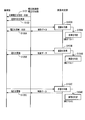
- the image determination unit shown in FIG. 5 corresponds to the image determination unit 130 in FIG.
- the image pickup unit, the voltage control unit, the voltage application unit, and the image determination unit shown in FIG. 5 are blocks of a system that controls the first image pickup unit 200A and acquires an image from the first image pickup unit 200A. .. That is, it is assumed that the image pickup unit, the voltage control unit, the voltage application unit, and the image determination unit are the first image pickup unit 200A, the first voltage control unit 121, the first voltage application unit 111, and the image determination unit 130. In that case, the second imaging unit 200B, the second voltage control unit 122, the second voltage applying unit 112, and the image determination unit 130 have a delay time T for the second imaging unit 200B with respect to the operation shown in FIG. After a delay, an operation similar to the operation shown in FIG. 5 is performed.
- the first voltage control unit 121 receives control data (indicating the start of processing) from the image determination unit 130.
- the first voltage control unit 121 sets voltage information (first voltage information) representing an initial value, and outputs the voltage information (first voltage information) to the first voltage application unit 111 and the second voltage control unit 122 (step S101).
- the first voltage application unit 111 applies an initial voltage to the liquid lens of the first imaging unit 200A according to the first voltage information (step S101).
- the initial voltage is, for example, a voltage for bringing the focus of the camera to the initial position, eg, the end closest to the camera in the focal movement range (see "front" in FIG. 1).
- the second voltage application unit 112 outputs the input first voltage information as the second voltage information to the second voltage application unit 112.
- the second voltage application unit 112 applies an initial voltage to the liquid lens of the second imaging unit 200B according to the second voltage information (step S101).
- the first voltage application unit 111 and the second voltage application unit 112 When the process of step S101 is executed, the first voltage application unit 111 and the second voltage application unit 112 output a lighting command to the lighting devices 202A and 202B.
- the lighting devices 202A and 202B emit light in response to the lighting command (step S102).
- the illumination devices 202A and 202B start light emission when the initial voltage is applied to the liquid lens, and end the light emission when the image determination unit 130 inputs the in-focus image. Therefore, in the present embodiment, the process of step S103 is executed only once.
- the first voltage application unit 111 and the second voltage application unit 112 may output a lighting command at each of the timings at which the first imaging unit 200A and the second imaging unit 200B perform imaging. good.
- first voltage application unit 111 and the second voltage application unit 112 may output a lighting command to the lighting devices 202A and 202B before applying the voltage to the first imaging unit 200A and the second imaging unit 200B.
- the application of voltage and the output of the lighting command may be started at the same time.
- the image determination unit 130 inputs an image (iris image) taken by each of the first imaging unit 200A and the second imaging unit 200B (step S103A). That is, the images taken by the first imaging unit 200A and the second imaging unit 200B are acquired.
- the image determination unit 130 acquires an image from the second imaging unit 200B after a delay time T has elapsed from the time when the image was acquired from the first imaging unit 200A.
- the image determination unit 130 confirms whether or not the acquired image is appropriate (step S104A).
- the image determination unit 130 uses the sharpness of the image, for example contrast, to check whether the input image is appropriate. Specifically, the image determination unit 130 detects the contrast of the image. Then, when the contrast exceeds a predetermined threshold value, the image determination unit 130 determines that the acquired image is an in-focus image taken at the in-focus position and is an appropriate image. do. When it is determined that both the image input from the first imaging unit 200A and the image input from the second imaging unit 200B are appropriate, the image determination unit 130 appropriates the image having the higher contrast. Suppose it is an image.
- the image determination unit 130 outputs control data indicating an update of the applied voltage (increase or decrease of the voltage value) to the first voltage control unit 121.
- the first voltage control unit 121 outputs voltage information (first voltage information) capable of specifying the updated voltage value to the first voltage application unit 111 and the second voltage control unit 122. (Step S105A).
- the image determination unit 130 acquires an image from the first imaging unit 200A. Then, the control data indicating the update of the applied voltage is output. However, it is not essential that the image determination unit 130 outputs control data indicating the update of the applied voltage when the image determination unit 130 acquires the image. For example, the image determination unit 130 asynchronously with the image acquisition time (for example, as an example). Image acquisition interval: 16 ms, voltage update interval: 100 ms) Control data indicating the update of the applied voltage may be output. In that case, the image determination unit 130 acquires a plurality of images from the time when the voltage value is updated until the next time the voltage value is updated.
- FIG. 5 shows an example in which it is determined that an appropriate image was not acquired by the process of step S104B after the process of step S105A (update / application of voltage) was executed. Then, an example is shown in which it is determined that an appropriate image has been acquired by the process of step S104C after the process of step S105B (update / application of voltage) is executed.
- the in-focus image is an image obtained when the eyelids of the subject 50 are closed by blinking or the like, that is, even if an in-focus image unsuitable for iris recognition is obtained.
- an in-focus image capable of performing iris recognition or the like can be obtained. That is, in the example shown in FIG. 1 (B), when the first in-focus image obtained is an image that is not suitable for iris recognition, it is suitable for iris recognition unless at least the "time to return" has elapsed. I can't get a focus image.
- the first in-focus image obtained is an image unsuitable for iris recognition
- the present embodiment there is an increased possibility that an in-focus image suitable for iris recognition can be obtained in a short time. Therefore, as a result, it is possible to shorten the time until the image used for the image processing is obtained.
- the first voltage control unit 121 and the second voltage control unit 122 are separately provided, but the voltage including the function of the first voltage control unit 121 and the function of the second voltage control unit 122.
- a control unit may be provided.
- Such a voltage control unit outputs the above-mentioned first voltage information, and also executes delay processing related to the second voltage information to output the above-mentioned second voltage information.
- the first imaging unit 200A and the second imaging unit 200B incorporating the liquid lens are used, but at least one of the first imaging unit 200A and the second imaging unit 200B is physically driven by a motor. It is also possible to use a lens that is driven specifically.
- Embodiment 2 For iris authentication, a registration phase in which a large number of subject 50 iris features are registered in a database or the like is compared with a large number of iris features registered in the database or the like and the iris feature of one subject 50. There is an authentication phase.
- a wavelength band of 850 nm and a wavelength band of 940 nm are widely used.
- the wavelength band used in the registration phase and the wavelength band used in the authentication phase are different.
- the iris feature quantity obtained from each of the image obtained by using the light of the wavelength band of 850 nm and the image obtained by using the light of the wavelength band of 940 nm can be registered in a database or the like. preferable.
- the wavelengths of the light emitted by the lighting devices 202A and 202B are different.
- one is light having a wavelength of 850 nm and the other is light having a wavelength of 940 nm.
- a bandpass filter is attached to each of the first imaging unit 200A and the second imaging unit 200B.
- the pass band of one bandpass filter is the 850 nm band
- the pass band of the other bandpass filter is the 940 nm band.
- the delay control as illustrated in FIG. 1C is not executed. That is, the two imaging units together change the focal length. Further, in the present embodiment, light having a wavelength band of 850 nm and light having a wavelength band of 940 nm are used, but the wavelength of the light used is not limited thereto.
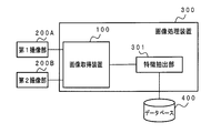
- FIG. 6 is a block diagram showing an image processing apparatus according to a third embodiment.
- the image processing device 300 shown in FIG. 6 includes the image acquisition device 100 of the first embodiment and the feature extraction unit 301.
- the feature extraction unit 301 inputs an image determined by the image determination unit 130 in the image acquisition device 100 to be an appropriate image.
- the feature extraction unit 301 extracts an iris region (excluding the pupil) from the input image and generates a feature amount (iris feature amount) of the iris region. Then, the feature extraction unit 301 stores the iris feature amount in the database 400.
- the image processing device 300 shown in FIG. 6 executes the processing of the registration phase in the iris authentication. Further, the feature extraction unit 301 can use an existing arbitrary feature amount generation algorithm when generating the iris feature amount.
- the in-focus image output by the image acquisition device 100 is likely to be an image (an image suitable for iris recognition) obtained when the eyelids of the subject 50 are not closed. Therefore, in the present embodiment, as a result, the time required for processing the registration phase in iris recognition is shortened.
- FIG. 7 is a block diagram showing an image processing apparatus according to a fourth embodiment.
- the image processing device 310 shown in FIG. 7 includes the image acquisition device 100 of the first embodiment and the feature extraction / collation unit 302.
- the database 400 stores iris features of a large number of subjects.
- the feature extraction / collation unit 302 inputs an image determined by the image determination unit 130 in the image acquisition device 100 to be an appropriate image.
- the feature extraction / matching unit 302 extracts the iris region (excluding the pupil) from the input image and generates the iris feature amount of the subject 50. Then, the feature extraction / collation unit 302 compares (collates) the generated iris feature amount with a large number of iris feature amounts stored in the database 400. When the feature extraction / matching unit 302 matches the generated iris feature amount with any of the iris feature amounts stored in the database 400, it is assumed that the authentication of the subject 50 is successful.
- the in-focus image output by the image acquisition device 100 is likely to be an image (an image suitable for iris recognition) obtained when the eyelids of the subject 50 are not closed. Therefore, in the present embodiment, as a result, the time required for processing the authentication phase in iris recognition is shortened.
- an image processing device including an image acquisition device 100, a feature extraction unit 301, and a feature extraction / collation unit 302 may be formed.
- Each component (excluding the first voltage application unit 111 and the second voltage application unit 112) in the image acquisition device in each of the above embodiments can be configured by one hardware, but can also be configured by one software. be.
- each component can be configured by a plurality of hardware and can be configured by a plurality of software. It is also possible to configure a part of each component with hardware and the other part with software.
- Each function (each processing) in the above embodiment can be realized by a computer having a processor such as a CPU (Central Processing Unit) or a memory.
- a program for carrying out the method (processing) in the above embodiment may be stored in a storage device (storage medium), and each function may be realized by executing the program stored in the storage device on the CPU. good.
- any one of GPU (Graphics Processing Unit), FPGA (Field-Programmable Gate Array), DSP (Digital Signal Processor), and ASIC (Application Specific Integrated Circuit) may be used.
- a plurality of CPUs, GPUs, FPGAs, DSPs, and ASICs may be used in parallel.
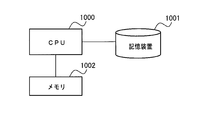
- FIG. 8 is a block diagram showing an example of a computer having a CPU.
- the computer can be mounted on the image acquisition device 100 and the image processing devices 300 and 310.
- the CPU 1000 realizes each function in the above embodiment by executing a process according to a program (software element: code) stored in the storage device 1001. That is, in the image acquisition device 100 and the image processing devices 300 and 310 shown in FIGS. 2, 6 and 7, the first voltage control unit 121, the second voltage control unit 122, the image determination unit 130, and the feature extraction unit 301. , And the function of the feature extraction / collation unit 302 is realized.
- a program software element: code
- the storage device 1001 is, for example, a non-transitory computer readable medium.
- Non-temporary computer-readable media include various types of tangible storage media. Specific examples of non-temporary computer-readable media include magnetic recording media (for example, hard disks), magneto-optical recording media (for example, magneto-optical disks), CD-ROMs (Compact Disc-Read Only Memory), and CD-Rs (Compact). Disc-Recordable), CD-R / W (CompactDisc-ReWritable), semiconductor memory (for example, mask ROM, PROM (ProgrammableROM), EPROM (ErasablePROM), flash ROM).
- the storage device 1001 can also be used as a database 400.
- the program may be stored in various types of temporary computer readable media (transitory computer readable medium).
- the program is supplied to the temporary computer-readable medium, for example, via a wired or wireless channel, that is, via an electrical signal, an optical signal, or an electromagnetic wave.
- the memory 1002 is realized by, for example, a RAM (Random Access Memory), and is a storage means for temporarily storing data when the CPU 1000 executes a process. It is also possible to envision a form in which a program held by the storage device 1001 or a temporary computer-readable medium is transferred to the memory 1002, and the CPU 1000 executes processing based on the program in the memory 1002.
- a RAM Random Access Memory
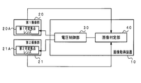
- FIG. 9 is a block diagram showing a main part of the image acquisition device.
- the image acquisition device 10 shown in FIG. 9 is included in a first imaging unit (first imaging means) 20 (in the embodiment, realized by the first imaging unit 200A) installed at a position where a subject can be photographed.
- a first varifocal lens whose focal length changes according to the applied voltage (in the embodiment, realized by the liquid lens 211) 20A is generated to generate first voltage information capable of specifying the voltage applied to the subject.
- a second image pickup unit (second image pickup means) 21 (in the embodiment, realized by the second image pickup unit 200B) installed at a position where an image can be taken, and the focal length changes according to the applied voltage.
- a voltage control unit (voltage control means) 30 (in the embodiment, the first) that generates second voltage information capable of specifying the voltage applied to the 21A. It is realized by the 1st voltage control unit 121 and the 2nd voltage control unit 122), and images are input from the 1st imaging unit 20 and the 2nd imaging unit 21, and the images taken from the input images at the focal length position.
- the voltage control unit 30 includes an image determination unit (image determination means) 40 (in the embodiment, realized by the image determination unit 130), and the voltage control unit 30 uses the value as the first voltage information with the passage of time. Information that can identify each voltage in the changing time series voltage is generated, and as the second voltage information, each voltage specified by the first voltage information is applied to the second varifocal lens 21A with a delay of a predetermined period. Generate identifiable information.
- First voltage information that can specify the voltage applied to the first varifocal lens, which is included in the first imaging means installed at a position where the subject can be photographed and whose focal length changes according to the applied voltage.
- a second voltage that can specify the voltage applied to the second varifocal lens, which is included in the second imaging means installed at a position where the subject can be photographed and whose focal length changes according to the applied voltage.
- Voltage control means to generate information and An image determining means for inputting an image from the first imaging means and the second imaging means and selecting one image taken at a focusing position from the input image is provided.
- the voltage control means As the first voltage information, information that can identify each voltage in a time-series voltage whose value changes with the passage of time is generated.
- the image acquisition is characterized in that, as the second voltage information, information that can be specified that each voltage specified by the first voltage information is applied to the second variable focus lens with a delay of a predetermined period is generated.
- Appendix 2 The image acquisition device according to Appendix 1, wherein the predetermined period is a time selected from 100 to 300 ms.
- the image determination means selects an image in which the contrast of the image exceeds a predetermined value from the images input from the first imaging means and the second imaging means. Image acquisition of Appendix 1 or Appendix 2. Device.
- Appendix 4 A first voltage applying means for applying a voltage having a value specified by the first voltage information to the first varifocal lens, and An image acquisition device according to any one of Appendix 1 to Appendix 3, further comprising a second voltage applying means for applying a voltage of a value specified by the second voltage information to the second varifocal lens.
- the first voltage applying means applies a voltage to the liquid lens as the first variable focus lens.
- the second voltage applying means is an image acquisition device according to Appendix 4, which applies a voltage to a liquid lens as the second varifocal lens.
- Appendix 6 An image acquisition device from any of the appendices 1 to 5 and An image processing apparatus including a feature extraction means for generating a feature amount of the iris region of the subject from a focused image selected by the image determination means.
- An image acquisition device from any of the appendices 1 to 5 and A feature extraction / matching means for generating a feature amount in the iris region of the subject from the in-focus image selected by the image determination means and collating the feature amount with the feature amount in the iris region acquired in advance is provided.
- Image processing device An image acquisition device from any of the appendices 1 to 5 and A feature extraction / matching means for generating a feature amount in the iris region of the subject from the in-focus image selected by the image determination means and collating the feature amount with the feature amount in the iris region acquired in advance is provided.
- Image processing device is provided.
- An image acquisition device from any of the appendices 1 to 5 and A feature extraction means for generating a feature amount in the iris region of the subject from a focused image selected by the image determination means, and a feature extraction means. It is provided with a feature extraction / matching means that generates a feature amount of the iris region of the subject from the focused image selected by the image determination means and collates the feature amount with the feature amount of the iris region acquired in advance.
- Image processing device
- First voltage information that can specify the voltage applied to the first varifocal lens, which is included in the first imaging means installed at a position where the subject can be photographed and whose focal length changes according to the applied voltage.
- a second voltage that can specify the voltage applied to the second varifocal lens, which is included in the second imaging means installed at a position where the subject can be photographed and whose focal length changes according to the applied voltage.
- the first voltage information is information that can specify each voltage in a time-series voltage whose value changes with the passage of time.
- the second voltage information is information that can identify that each voltage specified by the first voltage information is applied to the second varifocal lens with a delay of a predetermined period.
- An image acquisition method comprising selecting one image taken at a focused position from the images input from the first imaging means and the second imaging means.
- Appendix 10 The image acquisition method of Appendix 9, wherein the predetermined period is a time selected from 100 to 300 ms.
- Appendix 11 The image acquisition method of Appendix 8 or Appendix 9 for selecting an image in which the contrast of the image exceeds a predetermined value from the images input from the first imaging means and the second imaging means.
- the first voltage information is information that can specify each voltage in a time-series voltage whose value changes with the passage of time.
- the second voltage information is information that can identify that each voltage specified by the first voltage information is applied to the second varifocal lens with a delay of a predetermined period.
- Appendix 13 To the computer The image acquisition program of Appendix 12 for executing a process of selecting an image whose contrast of an image exceeds a predetermined value from the images input from the first imaging means and the second imaging means.
- the image acquisition program is applied to a computer.
- the first voltage information is information that can specify each voltage in a time-series voltage whose value changes with the passage of time.
- the second voltage information is information that can identify that each voltage specified by the first voltage information is applied to the second varifocal lens with a delay of a predetermined period.
- the image acquisition program is applied to a computer.
- Appendix 15 The image acquisition program is applied to a computer.
- the recording medium of Appendix 14 for executing a process of selecting an image in which the contrast of the image exceeds a predetermined value from the images input from the first imaging means and the second imaging means.
- Image acquisition device 20 1st image sensor 21 2nd image sensor 20A 1st varifocal lens 21A 2nd varifocal lens 30 Voltage control unit 40 Image judgment unit 50 Target person 100 Image acquisition device 111 1st voltage application unit 112 2nd Voltage application unit 121 1st voltage control unit 122 2nd voltage control unit 130 Image judgment unit 200 Imaging unit 200A 1st imaging unit 200B 2nd imaging unit 202A, 202B Lighting device 211 Liquid lens 212 Image sensor 300, 310 Image processing device 301 Feature extraction unit 302 Feature extraction / collation unit 400 Database 1000 CPU 1001 storage device 1002 memory
Landscapes
- Engineering & Computer Science (AREA)
- Physics & Mathematics (AREA)
- General Physics & Mathematics (AREA)
- Multimedia (AREA)
- Signal Processing (AREA)
- Optics & Photonics (AREA)
- Human Computer Interaction (AREA)
- Theoretical Computer Science (AREA)
- Health & Medical Sciences (AREA)
- Computer Vision & Pattern Recognition (AREA)
- Ophthalmology & Optometry (AREA)
- General Health & Medical Sciences (AREA)
- Studio Devices (AREA)
- Focusing (AREA)
- Cameras In General (AREA)
- Automatic Focus Adjustment (AREA)
Priority Applications (4)
| Application Number | Priority Date | Filing Date | Title |
|---|---|---|---|
| EP20921065.7A EP4113968B1 (en) | 2020-02-28 | 2020-02-28 | Image acquiring device, image acquiring method, and image acquiring program |
| PCT/JP2020/008421 WO2021171586A1 (ja) | 2020-02-28 | 2020-02-28 | 画像取得装置、画像取得方法および画像処理装置 |
| US17/801,925 US12010422B2 (en) | 2020-02-28 | 2020-02-28 | Image acquiring device, image acquiring method, and image processing device |
| JP2022503026A JP7355213B2 (ja) | 2020-02-28 | 2020-02-28 | 画像取得装置、画像取得方法および画像処理装置 |
Applications Claiming Priority (1)
| Application Number | Priority Date | Filing Date | Title |
|---|---|---|---|
| PCT/JP2020/008421 WO2021171586A1 (ja) | 2020-02-28 | 2020-02-28 | 画像取得装置、画像取得方法および画像処理装置 |
Publications (1)
| Publication Number | Publication Date |
|---|---|
| WO2021171586A1 true WO2021171586A1 (ja) | 2021-09-02 |
Family
ID=77492063
Family Applications (1)
| Application Number | Title | Priority Date | Filing Date |
|---|---|---|---|
| PCT/JP2020/008421 Ceased WO2021171586A1 (ja) | 2020-02-28 | 2020-02-28 | 画像取得装置、画像取得方法および画像処理装置 |
Country Status (4)
| Country | Link |
|---|---|
| US (1) | US12010422B2 (cg-RX-API-DMAC7.html) |
| EP (1) | EP4113968B1 (cg-RX-API-DMAC7.html) |
| JP (1) | JP7355213B2 (cg-RX-API-DMAC7.html) |
| WO (1) | WO2021171586A1 (cg-RX-API-DMAC7.html) |
Cited By (1)
| Publication number | Priority date | Publication date | Assignee | Title |
|---|---|---|---|---|
| EP4403974A4 (en) * | 2021-09-14 | 2024-10-16 | NEC Corporation | INFORMATION PROCESSING SYSTEM, INFORMATION PROCESSING DEVICE, INFORMATION PROCESSING METHOD, AND RECORDING MEDIUM |
Citations (7)
| Publication number | Priority date | Publication date | Assignee | Title |
|---|---|---|---|---|
| WO2008016035A1 (en) * | 2006-08-01 | 2008-02-07 | Panasonic Corporation | Camera device, liquid lens and image pickup method |
| JP2010258552A (ja) | 2009-04-22 | 2010-11-11 | Casio Computer Co Ltd | 撮像装置、撮像方法及びプログラム |
| US20130089240A1 (en) * | 2011-10-07 | 2013-04-11 | Aoptix Technologies, Inc. | Handheld iris imager |
| JP2016510628A (ja) * | 2013-03-14 | 2016-04-11 | レイセオン カンパニー | 携帯型網膜画像化装置 |
| JP2017083962A (ja) | 2015-10-23 | 2017-05-18 | 日本電産リード株式会社 | 虹彩認証装置、及び虹彩認証装置付車両 |
| US20170168200A1 (en) * | 2015-12-09 | 2017-06-15 | Fotonation Limited | Image acquisition system |
| US20190273873A1 (en) * | 2018-03-02 | 2019-09-05 | Zkteco Usa, Llc | Method and System for Iris Recognition |
Family Cites Families (5)
| Publication number | Priority date | Publication date | Assignee | Title |
|---|---|---|---|---|
| JP5571179B2 (ja) | 2010-05-14 | 2014-08-13 | 富士フイルム株式会社 | 立体撮像装置及び立体撮像装置の自動焦点調節方法 |
| US20130194548A1 (en) | 2011-04-07 | 2013-08-01 | Raytheon Company | Portable retinal imaging device |
| JP5762211B2 (ja) | 2011-08-11 | 2015-08-12 | キヤノン株式会社 | 画像処理装置および画像処理方法、プログラム |
| WO2015117905A1 (de) * | 2014-02-04 | 2015-08-13 | Fraunhofer-Gesellschaft zur Förderung der angewandten Forschung e.V. | 3d-bildanalysator zur blickrichtungsbestimmung |
| US10250795B2 (en) | 2017-03-15 | 2019-04-02 | Motorola Mobility Llc | Identifying a focus point in a scene utilizing a plurality of cameras |
-
2020
- 2020-02-28 WO PCT/JP2020/008421 patent/WO2021171586A1/ja not_active Ceased
- 2020-02-28 JP JP2022503026A patent/JP7355213B2/ja active Active
- 2020-02-28 US US17/801,925 patent/US12010422B2/en active Active
- 2020-02-28 EP EP20921065.7A patent/EP4113968B1/en active Active
Patent Citations (7)
| Publication number | Priority date | Publication date | Assignee | Title |
|---|---|---|---|---|
| WO2008016035A1 (en) * | 2006-08-01 | 2008-02-07 | Panasonic Corporation | Camera device, liquid lens and image pickup method |
| JP2010258552A (ja) | 2009-04-22 | 2010-11-11 | Casio Computer Co Ltd | 撮像装置、撮像方法及びプログラム |
| US20130089240A1 (en) * | 2011-10-07 | 2013-04-11 | Aoptix Technologies, Inc. | Handheld iris imager |
| JP2016510628A (ja) * | 2013-03-14 | 2016-04-11 | レイセオン カンパニー | 携帯型網膜画像化装置 |
| JP2017083962A (ja) | 2015-10-23 | 2017-05-18 | 日本電産リード株式会社 | 虹彩認証装置、及び虹彩認証装置付車両 |
| US20170168200A1 (en) * | 2015-12-09 | 2017-06-15 | Fotonation Limited | Image acquisition system |
| US20190273873A1 (en) * | 2018-03-02 | 2019-09-05 | Zkteco Usa, Llc | Method and System for Iris Recognition |
Cited By (2)
| Publication number | Priority date | Publication date | Assignee | Title |
|---|---|---|---|---|
| EP4403974A4 (en) * | 2021-09-14 | 2024-10-16 | NEC Corporation | INFORMATION PROCESSING SYSTEM, INFORMATION PROCESSING DEVICE, INFORMATION PROCESSING METHOD, AND RECORDING MEDIUM |
| US12236714B2 (en) | 2021-09-14 | 2025-02-25 | Nec Corporation | Information processing system, information processing apparatus, information processing method, and recording medium |
Also Published As
| Publication number | Publication date |
|---|---|
| EP4113968A4 (en) | 2023-04-05 |
| JPWO2021171586A1 (cg-RX-API-DMAC7.html) | 2021-09-02 |
| EP4113968A1 (en) | 2023-01-04 |
| EP4113968B1 (en) | 2025-02-19 |
| US12010422B2 (en) | 2024-06-11 |
| US20230100016A1 (en) | 2023-03-30 |
| JP7355213B2 (ja) | 2023-10-03 |
Similar Documents
| Publication | Publication Date | Title |
|---|---|---|
| JP6631808B2 (ja) | 虹彩利用生体認証のための装置および方法 | |
| JP5153862B2 (ja) | 高被写界深度撮像システム及び虹彩認証システム | |
| US9934436B2 (en) | System and method for 3D iris recognition | |
| US12217548B2 (en) | Authentication device, authentication method, and recording medium | |
| Da Costa et al. | Dynamic features for iris recognition | |
| CN109753925B (zh) | 一种虹膜特征提取的方法和设备 | |
| US20160364609A1 (en) | Apparatuses and methods for iris based biometric recognition | |
| US20120154536A1 (en) | Method and apparatus for automatically acquiring facial, ocular, and iris images from moving subjects at long-range | |
| WO2008091401A2 (en) | Multimodal ocular biometric system and methods | |
| JP3879719B2 (ja) | 画像入力装置およびそれを用いた認証装置 | |
| US11160449B2 (en) | Focus stacking for retinal imaging | |
| CN110532849B (zh) | 用于面部检测的多光谱图像处理系统 | |
| US20160366317A1 (en) | Apparatuses and methods for image based biometric recognition | |
| JP7400949B2 (ja) | 撮像システム、撮像方法及び撮像プログラム | |
| JP7655345B2 (ja) | 情報処理システム、照明制御装置、照明制御方法、及びプログラム | |
| JP6916283B2 (ja) | 多焦点ケラトメトリを用いた眼表面形状の特定 | |
| JP7355213B2 (ja) | 画像取得装置、画像取得方法および画像処理装置 | |
| JP3848953B2 (ja) | 生体眼判定方法および生体眼判定装置 | |
| US12494079B2 (en) | Imaging apparatus and imaging method | |
| WO2020009126A1 (ja) | 認証装置、及び認証方法 | |
| CN109978932B (zh) | 利用结构光获取检测对象的深度信息的系统和方法 | |
| JP7800650B2 (ja) | 情報処理装置、情報処理方法及び記録媒体 | |
| WO2020170892A1 (ja) | 撮像装置、方法、システム、及びコンピュータ可読媒体 | |
| JP2008052317A (ja) | 認証装置および認証方法 | |
| JP4527088B2 (ja) | 生体眼判定方法および生体眼判定装置 |
Legal Events
| Date | Code | Title | Description |
|---|---|---|---|
| 121 | Ep: the epo has been informed by wipo that ep was designated in this application |
Ref document number: 20921065 Country of ref document: EP Kind code of ref document: A1 |
|
| ENP | Entry into the national phase |
Ref document number: 2022503026 Country of ref document: JP Kind code of ref document: A |
|
| NENP | Non-entry into the national phase |
Ref country code: DE |
|
| ENP | Entry into the national phase |
Ref document number: 2020921065 Country of ref document: EP Effective date: 20220928 |