WO2021171529A1 - 積層体および積層方法 - Google Patents
積層体および積層方法 Download PDFInfo
- Publication number
- WO2021171529A1 WO2021171529A1 PCT/JP2020/008205 JP2020008205W WO2021171529A1 WO 2021171529 A1 WO2021171529 A1 WO 2021171529A1 JP 2020008205 W JP2020008205 W JP 2020008205W WO 2021171529 A1 WO2021171529 A1 WO 2021171529A1
- Authority
- WO
- WIPO (PCT)
- Prior art keywords
- composite sheet
- longitudinal direction
- composite
- sheets
- longitudinal
- Prior art date
- Legal status (The legal status is an assumption and is not a legal conclusion. Google has not performed a legal analysis and makes no representation as to the accuracy of the status listed.)
- Ceased
Links
Images





Classifications
-
- B—PERFORMING OPERATIONS; TRANSPORTING
- B32—LAYERED PRODUCTS
- B32B—LAYERED PRODUCTS, i.e. PRODUCTS BUILT-UP OF STRATA OF FLAT OR NON-FLAT, e.g. CELLULAR OR HONEYCOMB, FORM
- B32B5/00—Layered products characterised by the non- homogeneity or physical structure, i.e. comprising a fibrous, filamentary, particulate or foam layer; Layered products characterised by having a layer differing constitutionally or physically in different parts
- B32B5/02—Layered products characterised by the non- homogeneity or physical structure, i.e. comprising a fibrous, filamentary, particulate or foam layer; Layered products characterised by having a layer differing constitutionally or physically in different parts characterised by structural features of a fibrous or filamentary layer
- B32B5/12—Layered products characterised by the non- homogeneity or physical structure, i.e. comprising a fibrous, filamentary, particulate or foam layer; Layered products characterised by having a layer differing constitutionally or physically in different parts characterised by structural features of a fibrous or filamentary layer characterised by the relative arrangement of fibres or filaments of different layers, e.g. the fibres or filaments being parallel or perpendicular to each other
-
- B—PERFORMING OPERATIONS; TRANSPORTING
- B29—WORKING OF PLASTICS; WORKING OF SUBSTANCES IN A PLASTIC STATE IN GENERAL
- B29C—SHAPING OR JOINING OF PLASTICS; SHAPING OF MATERIAL IN A PLASTIC STATE, NOT OTHERWISE PROVIDED FOR; AFTER-TREATMENT OF THE SHAPED PRODUCTS, e.g. REPAIRING
- B29C70/00—Shaping composites, i.e. plastics material comprising reinforcements, fillers or preformed parts, e.g. inserts
- B29C70/04—Shaping composites, i.e. plastics material comprising reinforcements, fillers or preformed parts, e.g. inserts comprising reinforcements only, e.g. self-reinforcing plastics
- B29C70/28—Shaping operations therefor
- B29C70/30—Shaping by lay-up, i.e. applying fibres, tape or broadsheet on a mould, former or core; Shaping by spray-up, i.e. spraying of fibres on a mould, former or core
-
- B—PERFORMING OPERATIONS; TRANSPORTING
- B29—WORKING OF PLASTICS; WORKING OF SUBSTANCES IN A PLASTIC STATE IN GENERAL
- B29C—SHAPING OR JOINING OF PLASTICS; SHAPING OF MATERIAL IN A PLASTIC STATE, NOT OTHERWISE PROVIDED FOR; AFTER-TREATMENT OF THE SHAPED PRODUCTS, e.g. REPAIRING
- B29C70/00—Shaping composites, i.e. plastics material comprising reinforcements, fillers or preformed parts, e.g. inserts
- B29C70/04—Shaping composites, i.e. plastics material comprising reinforcements, fillers or preformed parts, e.g. inserts comprising reinforcements only, e.g. self-reinforcing plastics
- B29C70/06—Fibrous reinforcements only
- B29C70/10—Fibrous reinforcements only characterised by the structure of fibrous reinforcements, e.g. hollow fibres
- B29C70/16—Fibrous reinforcements only characterised by the structure of fibrous reinforcements, e.g. hollow fibres using fibres of substantial or continuous length
- B29C70/20—Fibrous reinforcements only characterised by the structure of fibrous reinforcements, e.g. hollow fibres using fibres of substantial or continuous length oriented in a single direction, e.g. roofing or other parallel fibres
- B29C70/202—Fibrous reinforcements only characterised by the structure of fibrous reinforcements, e.g. hollow fibres using fibres of substantial or continuous length oriented in a single direction, e.g. roofing or other parallel fibres arranged in parallel planes or structures of fibres crossing at substantial angles, e.g. cross-moulding compound [XMC]
-
- B—PERFORMING OPERATIONS; TRANSPORTING
- B29—WORKING OF PLASTICS; WORKING OF SUBSTANCES IN A PLASTIC STATE IN GENERAL
- B29C—SHAPING OR JOINING OF PLASTICS; SHAPING OF MATERIAL IN A PLASTIC STATE, NOT OTHERWISE PROVIDED FOR; AFTER-TREATMENT OF THE SHAPED PRODUCTS, e.g. REPAIRING
- B29C70/00—Shaping composites, i.e. plastics material comprising reinforcements, fillers or preformed parts, e.g. inserts
- B29C70/04—Shaping composites, i.e. plastics material comprising reinforcements, fillers or preformed parts, e.g. inserts comprising reinforcements only, e.g. self-reinforcing plastics
- B29C70/06—Fibrous reinforcements only
- B29C70/10—Fibrous reinforcements only characterised by the structure of fibrous reinforcements, e.g. hollow fibres
- B29C70/16—Fibrous reinforcements only characterised by the structure of fibrous reinforcements, e.g. hollow fibres using fibres of substantial or continuous length
- B29C70/20—Fibrous reinforcements only characterised by the structure of fibrous reinforcements, e.g. hollow fibres using fibres of substantial or continuous length oriented in a single direction, e.g. roofing or other parallel fibres
- B29C70/205—Fibrous reinforcements only characterised by the structure of fibrous reinforcements, e.g. hollow fibres using fibres of substantial or continuous length oriented in a single direction, e.g. roofing or other parallel fibres the structure being shaped to form a three-dimensional configuration
-
- B—PERFORMING OPERATIONS; TRANSPORTING
- B29—WORKING OF PLASTICS; WORKING OF SUBSTANCES IN A PLASTIC STATE IN GENERAL
- B29C—SHAPING OR JOINING OF PLASTICS; SHAPING OF MATERIAL IN A PLASTIC STATE, NOT OTHERWISE PROVIDED FOR; AFTER-TREATMENT OF THE SHAPED PRODUCTS, e.g. REPAIRING
- B29C70/00—Shaping composites, i.e. plastics material comprising reinforcements, fillers or preformed parts, e.g. inserts
- B29C70/04—Shaping composites, i.e. plastics material comprising reinforcements, fillers or preformed parts, e.g. inserts comprising reinforcements only, e.g. self-reinforcing plastics
- B29C70/28—Shaping operations therefor
- B29C70/30—Shaping by lay-up, i.e. applying fibres, tape or broadsheet on a mould, former or core; Shaping by spray-up, i.e. spraying of fibres on a mould, former or core
- B29C70/304—In-plane lamination by juxtaposing or interleaving of plies, e.g. scarf joining
-
- B—PERFORMING OPERATIONS; TRANSPORTING
- B32—LAYERED PRODUCTS
- B32B—LAYERED PRODUCTS, i.e. PRODUCTS BUILT-UP OF STRATA OF FLAT OR NON-FLAT, e.g. CELLULAR OR HONEYCOMB, FORM
- B32B3/00—Layered products comprising a layer with external or internal discontinuities or unevennesses, or a layer of non-planar shape; Layered products comprising a layer having particular features of form
- B32B3/02—Layered products comprising a layer with external or internal discontinuities or unevennesses, or a layer of non-planar shape; Layered products comprising a layer having particular features of form characterised by features of form at particular places, e.g. in edge regions
- B32B3/08—Layered products comprising a layer with external or internal discontinuities or unevennesses, or a layer of non-planar shape; Layered products comprising a layer having particular features of form characterised by features of form at particular places, e.g. in edge regions characterised by added members at particular parts
-
- B—PERFORMING OPERATIONS; TRANSPORTING
- B32—LAYERED PRODUCTS
- B32B—LAYERED PRODUCTS, i.e. PRODUCTS BUILT-UP OF STRATA OF FLAT OR NON-FLAT, e.g. CELLULAR OR HONEYCOMB, FORM
- B32B3/00—Layered products comprising a layer with external or internal discontinuities or unevennesses, or a layer of non-planar shape; Layered products comprising a layer having particular features of form
- B32B3/10—Layered products comprising a layer with external or internal discontinuities or unevennesses, or a layer of non-planar shape; Layered products comprising a layer having particular features of form characterised by a discontinuous layer, i.e. formed of separate pieces of material
- B32B3/18—Layered products comprising a layer with external or internal discontinuities or unevennesses, or a layer of non-planar shape; Layered products comprising a layer having particular features of form characterised by a discontinuous layer, i.e. formed of separate pieces of material characterised by an internal layer formed of separate pieces of material which are juxtaposed side-by-side
-
- B—PERFORMING OPERATIONS; TRANSPORTING
- B32—LAYERED PRODUCTS
- B32B—LAYERED PRODUCTS, i.e. PRODUCTS BUILT-UP OF STRATA OF FLAT OR NON-FLAT, e.g. CELLULAR OR HONEYCOMB, FORM
- B32B37/00—Methods or apparatus for laminating, e.g. by curing or by ultrasonic bonding
- B32B37/02—Methods or apparatus for laminating, e.g. by curing or by ultrasonic bonding characterised by a sequence of laminating steps, e.g. by adding new layers at consecutive laminating stations
-
- B—PERFORMING OPERATIONS; TRANSPORTING
- B32—LAYERED PRODUCTS
- B32B—LAYERED PRODUCTS, i.e. PRODUCTS BUILT-UP OF STRATA OF FLAT OR NON-FLAT, e.g. CELLULAR OR HONEYCOMB, FORM
- B32B37/00—Methods or apparatus for laminating, e.g. by curing or by ultrasonic bonding
- B32B37/14—Methods or apparatus for laminating, e.g. by curing or by ultrasonic bonding characterised by the properties of the layers
- B32B37/16—Methods or apparatus for laminating, e.g. by curing or by ultrasonic bonding characterised by the properties of the layers with all layers existing as coherent layers before laminating
- B32B37/18—Methods or apparatus for laminating, e.g. by curing or by ultrasonic bonding characterised by the properties of the layers with all layers existing as coherent layers before laminating involving the assembly of discrete sheets or panels only
- B32B37/182—Methods or apparatus for laminating, e.g. by curing or by ultrasonic bonding characterised by the properties of the layers with all layers existing as coherent layers before laminating involving the assembly of discrete sheets or panels only one or more of the layers being plastic
-
- B—PERFORMING OPERATIONS; TRANSPORTING
- B32—LAYERED PRODUCTS
- B32B—LAYERED PRODUCTS, i.e. PRODUCTS BUILT-UP OF STRATA OF FLAT OR NON-FLAT, e.g. CELLULAR OR HONEYCOMB, FORM
- B32B5/00—Layered products characterised by the non- homogeneity or physical structure, i.e. comprising a fibrous, filamentary, particulate or foam layer; Layered products characterised by having a layer differing constitutionally or physically in different parts
- B32B5/02—Layered products characterised by the non- homogeneity or physical structure, i.e. comprising a fibrous, filamentary, particulate or foam layer; Layered products characterised by having a layer differing constitutionally or physically in different parts characterised by structural features of a fibrous or filamentary layer
-
- B—PERFORMING OPERATIONS; TRANSPORTING
- B32—LAYERED PRODUCTS
- B32B—LAYERED PRODUCTS, i.e. PRODUCTS BUILT-UP OF STRATA OF FLAT OR NON-FLAT, e.g. CELLULAR OR HONEYCOMB, FORM
- B32B5/00—Layered products characterised by the non- homogeneity or physical structure, i.e. comprising a fibrous, filamentary, particulate or foam layer; Layered products characterised by having a layer differing constitutionally or physically in different parts
- B32B5/22—Layered products characterised by the non- homogeneity or physical structure, i.e. comprising a fibrous, filamentary, particulate or foam layer; Layered products characterised by having a layer differing constitutionally or physically in different parts characterised by the presence of two or more layers which are next to each other and are fibrous, filamentary, formed of particles or foamed
- B32B5/24—Layered products characterised by the non- homogeneity or physical structure, i.e. comprising a fibrous, filamentary, particulate or foam layer; Layered products characterised by having a layer differing constitutionally or physically in different parts characterised by the presence of two or more layers which are next to each other and are fibrous, filamentary, formed of particles or foamed one layer being a fibrous or filamentary layer
- B32B5/26—Layered products characterised by the non- homogeneity or physical structure, i.e. comprising a fibrous, filamentary, particulate or foam layer; Layered products characterised by having a layer differing constitutionally or physically in different parts characterised by the presence of two or more layers which are next to each other and are fibrous, filamentary, formed of particles or foamed one layer being a fibrous or filamentary layer another layer next to it also being fibrous or filamentary
-
- B—PERFORMING OPERATIONS; TRANSPORTING
- B32—LAYERED PRODUCTS
- B32B—LAYERED PRODUCTS, i.e. PRODUCTS BUILT-UP OF STRATA OF FLAT OR NON-FLAT, e.g. CELLULAR OR HONEYCOMB, FORM
- B32B7/00—Layered products characterised by the relation between layers; Layered products characterised by the relative orientation of features between layers, or by the relative values of a measurable parameter between layers, i.e. products comprising layers having different physical, chemical or physicochemical properties; Layered products characterised by the interconnection of layers
- B32B7/03—Layered products characterised by the relation between layers; Layered products characterised by the relative orientation of features between layers, or by the relative values of a measurable parameter between layers, i.e. products comprising layers having different physical, chemical or physicochemical properties; Layered products characterised by the interconnection of layers with respect to the orientation of features
-
- B—PERFORMING OPERATIONS; TRANSPORTING
- B32—LAYERED PRODUCTS
- B32B—LAYERED PRODUCTS, i.e. PRODUCTS BUILT-UP OF STRATA OF FLAT OR NON-FLAT, e.g. CELLULAR OR HONEYCOMB, FORM
- B32B2250/00—Layers arrangement
- B32B2250/20—All layers being fibrous or filamentary
-
- B—PERFORMING OPERATIONS; TRANSPORTING
- B32—LAYERED PRODUCTS
- B32B—LAYERED PRODUCTS, i.e. PRODUCTS BUILT-UP OF STRATA OF FLAT OR NON-FLAT, e.g. CELLULAR OR HONEYCOMB, FORM
- B32B2250/00—Layers arrangement
- B32B2250/24—All layers being polymeric
-
- B—PERFORMING OPERATIONS; TRANSPORTING
- B32—LAYERED PRODUCTS
- B32B—LAYERED PRODUCTS, i.e. PRODUCTS BUILT-UP OF STRATA OF FLAT OR NON-FLAT, e.g. CELLULAR OR HONEYCOMB, FORM
- B32B2260/00—Layered product comprising an impregnated, embedded, or bonded layer wherein the layer comprises an impregnation, embedding, or binder material
- B32B2260/02—Composition of the impregnated, bonded or embedded layer
- B32B2260/021—Fibrous or filamentary layer
- B32B2260/023—Two or more layers
-
- B—PERFORMING OPERATIONS; TRANSPORTING
- B32—LAYERED PRODUCTS
- B32B—LAYERED PRODUCTS, i.e. PRODUCTS BUILT-UP OF STRATA OF FLAT OR NON-FLAT, e.g. CELLULAR OR HONEYCOMB, FORM
- B32B2260/00—Layered product comprising an impregnated, embedded, or bonded layer wherein the layer comprises an impregnation, embedding, or binder material
- B32B2260/04—Impregnation, embedding, or binder material
- B32B2260/046—Synthetic resin
-
- B—PERFORMING OPERATIONS; TRANSPORTING
- B32—LAYERED PRODUCTS
- B32B—LAYERED PRODUCTS, i.e. PRODUCTS BUILT-UP OF STRATA OF FLAT OR NON-FLAT, e.g. CELLULAR OR HONEYCOMB, FORM
- B32B2262/00—Composition or structural features of fibres which form a fibrous or filamentary layer or are present as additives
- B32B2262/10—Inorganic fibres
- B32B2262/101—Glass fibres
-
- B—PERFORMING OPERATIONS; TRANSPORTING
- B32—LAYERED PRODUCTS
- B32B—LAYERED PRODUCTS, i.e. PRODUCTS BUILT-UP OF STRATA OF FLAT OR NON-FLAT, e.g. CELLULAR OR HONEYCOMB, FORM
- B32B2262/00—Composition or structural features of fibres which form a fibrous or filamentary layer or are present as additives
- B32B2262/10—Inorganic fibres
- B32B2262/106—Carbon fibres, e.g. graphite fibres
-
- B—PERFORMING OPERATIONS; TRANSPORTING
- B32—LAYERED PRODUCTS
- B32B—LAYERED PRODUCTS, i.e. PRODUCTS BUILT-UP OF STRATA OF FLAT OR NON-FLAT, e.g. CELLULAR OR HONEYCOMB, FORM
- B32B2305/00—Condition, form or state of the layers or laminate
- B32B2305/10—Fibres of continuous length
-
- B—PERFORMING OPERATIONS; TRANSPORTING
- B32—LAYERED PRODUCTS
- B32B—LAYERED PRODUCTS, i.e. PRODUCTS BUILT-UP OF STRATA OF FLAT OR NON-FLAT, e.g. CELLULAR OR HONEYCOMB, FORM
- B32B2605/00—Vehicles
- B32B2605/18—Aircraft
Definitions
- the present disclosure relates to a laminate in which a second layer containing a plurality of second composite sheets is laminated in a state of being in contact with a first layer containing the plurality of first composite sheets, and a lamination method.
- Patent Document 1 discloses a method of cutting a flat rectangular laminated body into a desired shape and cutting it out in order to manufacture a component of a composite sheet extending in an in-plane curve.
- Patent Document 1 an unnecessary portion is generated when the composite sheet extending in the in-plane direction in a curved shape is cut out, so that all of the flat rectangular laminated body should be effectively utilized. This is not possible and the manufacturing cost increases.
- a component of a composite sheet extending in a curved direction in the in-plane direction for example, when a composite sheet extending linearly is used, it is necessary to stack the composite sheet while bending it in a curved shape.
- the composite sheet since the composite sheet has a property of being difficult to expand and contract, there is a possibility that the composite sheet is deformed in the plane and wrinkles are generated when the composite sheets are laminated. Then, when the wrinkled composite sheet is laminated over a plurality of layers, the production of the laminated body becomes defective.
- the present disclosure has been made in view of such circumstances, and provides a laminated body having a shape extending in an in-plane direction in a curved shape, a low manufacturing cost, and a high manufacturing quality, and a laminating method thereof.
- the purpose is to provide a laminated body having a shape extending in an in-plane direction in a curved shape, a low manufacturing cost, and a high manufacturing quality, and a laminating method thereof. The purpose.
- the laminate according to one aspect of the present disclosure is a first fiber group oriented in the first fiber direction having a first longitudinal direction and a first lateral direction and having a first predetermined angle with respect to the first longitudinal direction.
- a plurality of first composite sheets containing a material and a first resin material, and oriented in a second fiber direction having a second longitudinal direction and a second lateral direction and having a second predetermined angle with respect to the second longitudinal direction.
- a plurality of the second composite sheets including the second fiber base material and the second resin material are provided, and the plurality of the second composite sheets are in contact with the first layer including the plurality of the first composite sheets.
- the second layer including the sheet is laminated, and the plurality of the first composite sheets are the end portion of the first composite sheet adjacent to each other in the first longitudinal direction and the first composite sheet of the other.
- the ends in the longitudinal direction are close to each other without overlapping in the thickness direction, and the longitudinal direction of one of the first composite sheets intersects with the first longitudinal direction of the other first composite sheet.
- the plurality of second composite sheets are arranged along a curved arrangement direction, and the plurality of the second composite sheets are the end portion of the adjacent second composite sheet in the second longitudinal direction and the other second composite sheet.
- the ends in the second longitudinal direction are close to each other in a non-overlapping state in the thickness direction, and the second longitudinal direction of one of the second composite sheets and the second longitudinal direction of the second composite sheet of the other. Are arranged along the arrangement direction so as to intersect with each other.
- the laminating method is a laminating method for laminating a second layer containing a plurality of second composite sheets in a state of being in contact with a first layer containing a plurality of first composite sheets.
- the 1 composite sheet is a first fiber base material and a first resin material oriented in the first fiber direction having a first longitudinal direction and a first lateral direction and having a first predetermined angle with respect to the first longitudinal direction.
- the second composite sheet is formed in the form of a sheet containing the above, and is oriented in the direction of the second fiber having a second longitudinal direction and a second lateral direction and a second predetermined angle with respect to the second longitudinal direction.
- the first composite sheet is formed in the form of a sheet containing the second fiber base material and the second resin material, and the plurality of the first composite sheets are placed on one adjacent end of the first composite sheet in the first longitudinal direction and the other.
- the ends of the first composite sheet in the first longitudinal direction are close to each other without overlapping in the thickness direction, and the first composite sheet of one of the first composite sheets and the end of the first composite sheet of the other are close to each other.
- the portion and the other end of the second composite sheet in the second longitudinal direction are close to each other in a non-overlapping state in the thickness direction, and the second longitudinal direction of one of the second composite sheets and the other end of the second composite sheet are not overlapped with each other.
- a second laminating step of arranging the second composite sheet along the arrangement direction so as to intersect with the second longitudinal direction is provided.
- a laminated body having a shape extending in an in-plane direction in a curved shape, a low manufacturing cost, and a high strength, and a laminating method thereof.
- FIG. 7 is a plan view of the second composite sheet shown in FIG. 7.
- FIG. 11 is a cross-sectional view taken along the line AA of the laminated body shown in FIG. It is a flowchart which shows the manufacturing method of the composite material of this embodiment.
- FIG. 1 is a perspective view showing a panel structure according to an embodiment of the present disclosure.
- the panel structure of the present embodiment includes a frame 20 manufactured from the laminated body 100.
- the panel structure of this embodiment is a structure that constitutes a cylindrical fuselage of an aircraft.
- the face plate 17 and a plurality of ribs 12 provided parallel to each other on one surface of the face plate 17 are provided parallel to each other in a direction intersecting the extending direction of the rib 12.
- It has a plurality of frames 20 and the like.
- the frame 20 of the present embodiment is manufactured by shaping a planar laminate in which a composite sheet containing a fiber base material and a resin material is laminated over a plurality of layers (for example, 20 or more layers) into a Z shape. It is a thing.
- the frame 20 shown in FIG. 1 is Z-shaped, it may have another shape such as C-shaped.
- the direction in which the rib 12 extends is defined as the rib direction X
- the direction in which the frame 20 extends is defined as the frame direction (material axis direction) Y.
- the ribs 12 include a rib body 13 that rises vertically from one surface of the face plate 17, and a flange portion 14 that extends from the end of the rib body 13 in a direction parallel to the face plate 17. have. That is, the rib 12 has an L-shaped cross section perpendicular to the rib direction X, one arm portion of L forms the rib body 13, and the other arm portion of L forms a flange portion 14. There is.
- the frame 20 faces the frame main body 23 rising from one surface of the face plate 17 and the face plate 17, and is one side of the rib direction X from the end portion of the frame main body 23 on the face plate 17 side. It has a first flange portion 21 extending to the surface plate 17, and a second flange portion 22 facing the face plate 17 and extending from an end portion of the frame body 23 on the side far from the face plate 17 to the other side in the rib direction X. .. That is, in the frame 20, the shape of the cross section perpendicular to the frame direction Y forms a Z shape, one arm portion of Z forms the first flange portion 21, and the other arm portion of Z forms the second flange portion 22. Is made up of.
- the frame 20 has a shape extending in a curved shape in the in-plane direction of the frame main body 23 (the direction horizontal to the surface of the frame main body 23). That is, the frame 20 has an arc-shaped shape centered on the central axis of a substantially cylindrical aircraft fuselage (not shown) formed by combining panel structures.
- the laminated body 100 of the present embodiment will be described with reference to the drawings.
- a plurality of composite sheets are arranged along a curved arrangement direction AD to form a layer of the composite sheet, and the layers of the composite sheet are laminated over the plurality of layers.
- one layer is formed by arranging six composite sheets continuously along the arrangement direction AD, and the layers of the composite sheet are laminated in six layers.
- Other aspects may be used.
- one layer may be composed of an arbitrary number of composite sheets different from six
- the composite sheet may be composed of an arbitrary number of composite sheets different from six.
- the composite sheet laminated as the laminated body 100 is a sheet-like material containing a fiber base material (for example, carbon fiber, glass fiber) and a resin material.
- a resin material for example, carbon fiber, glass fiber
- a thermosetting resin or a thermoplastic resin can be used as the resin material.
- the thermosetting resin is, for example, an epoxy resin, an unsaturated polyester, a vinyl ester, a phenol, a cyanate ester, a polyimide, or the like.
- the thermoplastic resin is, for example, polyetheretherketone (PEEK), polyethylene terephthalate (PET), polybutylene terephthalate (PBT), nylon 6 (PA6), nylon 66 (PA66), polyphenylene sulfide (PPS), polyether. Imid (PEI), polyetherketoneketone (PEKK) and the like.
- PEEK polyetheretherketone
- PET polyethylene terephthalate
- PBT polybutylene terephthalate
- PA6 nylon 6
- PA66 nylon 66
- PPS polyphenylene sulfide
- PEI polyetherketoneketone
- PEKK polyetherketoneketone
- FIG. 2 is a plan view showing a laminated body in which a plurality of first composite sheets 110 are loaded on the laminated surface Su.
- FIG. 3 is a partially enlarged view of the laminated body 100 shown in FIG.
- FIG. 4 is a plan view of the first composite sheet 110 shown in FIG.
- FIG. 5 is a diagram showing the relationship between the first longitudinal LD1c of one adjacent first composite sheet 110c and the first longitudinal LD1d of the other first composite sheet 110d. Since the laminate 100 of the present embodiment is finally laminated in 6 layers, the laminate 100 shown in FIGS. 2 and 3 is at a stage before the lamination is completed.
- the laminated body 100 of the present embodiment has an end portion in the longitudinal direction (first longitudinal direction) of one adjacent first composite sheet 110 and a longitudinal direction (first) of the other first composite sheet 110. 1
- the end portions in the longitudinal direction) are arranged close to each other in a state where they do not overlap with each other in the thickness direction (thickness direction TD shown in FIG. 12).
- the first composite sheet 110 is a sheet-like material containing a fiber base material (first fiber base material) and a resin material (first resin material).
- the laminated surface Su shown in FIG. 2 is a surface on which a composite sheet is installed for laminating a plurality of layers of composite sheets including a plurality of first composite sheets 110.
- the thickness direction is a direction orthogonal to the laminated surface Su, and is a direction in which the thickness of the laminated body 100 is increased by laminating a plurality of layers of composite sheets.
- the plurality of first composite sheets 110 are the first composite sheet 110a, the first composite sheet 110b, and the first composite sheet 110b along the arrangement direction AD passing on the arc of the radius R1 centered on the point O.
- the 1 composite sheet 110c, the 1st composite sheet 110d, the 1st composite sheet 110e, and the 1st composite sheet 110f are arranged clockwise in this order.
- the arrangement direction AD is a direction of passing on an arc having a radius R1 centered on the point O, but other embodiments may be used.
- the arrangement direction AD may be a direction along any other curve, for example, a direction extending along a curve that bends in a certain direction.
- the plurality of first composite sheets 110 are arranged so that positions P11 to P17 are end positions (first end positions).
- the longitudinal ends of the first composite sheet 110a are located at positions P11 and P12
- the longitudinal ends of the first composite sheet 110b are located at positions P12 and P13
- the longitudinal ends of the first composite sheet 110c are located at positions P13 and P14.
- the longitudinal ends of the first composite sheet 110d are located at positions P14 and P15
- the longitudinal ends of the first composite sheet 110e are located at positions P15 and P16
- the longitudinal ends of the first composite sheet 110f The ends of the are arranged at positions P16 and P17.
- the first composite sheet 110c has a first longitudinal direction LD1c along the arrangement direction AD and a first lateral direction SD1c orthogonal to the first longitudinal direction LD1c in the plane of the first composite sheet 110c.
- the first composite sheet 110d has a first longitudinal direction LD1d along the arrangement direction AD and a first lateral direction SD1d orthogonal to the first longitudinal direction LD1d.
- the first composite sheet 110e has a first longitudinal direction LD1e along the arrangement direction AD and a first lateral direction SD1e orthogonal to the first longitudinal direction LD1e.
- the first composite sheet 110a, the first composite sheet 110b, the first composite sheet 110e, and the first composite sheet 110f also have a first longitudinal direction LD1 and a first lateral direction SD1 orthogonal to the first longitudinal direction LD1.
- the first composite sheet 110d is on the other side of the first lateral SD1d than the length of the first longitudinal LD1d on one side of the first lateral SD1d (inner peripheral side with respect to the point O).
- the length of the first longitudinal direction LD1d at (the outer peripheral side with respect to the point O) is long and has a trapezoidal shape with equal legs.
- the other first composite sheet 110 (110a, 110b, 110c, 110e, 110f) has the same shape.
- the laminate 100 of the present embodiment has the edge of the first longitudinal LD1 of the other first composite sheet 110 adjacent to the edge of the first longitudinal LD1 of the first composite sheet 110 having a trapezoidal shape with equal legs. It is arranged without a gap along the arrangement direction AD so as to coincide with the position of the side of the portion.
- the line on the surface of the first composite sheet 110d shown in FIG. 4 indicates the fiber direction (first fiber direction FD1) in which the fiber base material contained in the first composite sheet 110d is oriented.
- the first fiber direction FD1d of the first composite sheet 110d has a predetermined angle ⁇ (first predetermined angle) with respect to the first longitudinal direction LD1d.
- the first predetermined angle ⁇ shown in FIG. 4 is 90 degrees.
- the laminate 100 of the present embodiment has the same angle (90) of the first fiber direction FD1 with respect to the first longitudinal direction (LD1) of the plurality of first composite sheets 110 constituting the first layer. Degree).
- the fiber directions of the second to sixth layers with respect to the longitudinal direction of the plurality of composite sheets constituting each layer are the same.
- the first fiber direction FD1 of the first composite sheet 110 laminated to the first layer has an angle of 90 degrees with respect to the first longitudinal direction LD1, but other embodiments may also be used. good.
- the angles (first predetermined angles) formed by the first fiber direction FD1 and the first longitudinal direction LD1d of the first composite sheet 110 laminated on the first layer are 0 degrees (same direction), 45 degrees, and ⁇ 45. It may be in any direction such as degree.
- each of the first composite sheet 110a, 110b, 110c, 110d, 110e, 110f is a first longitudinal LD1 of one adjacent first composite sheet 110 and the other first composite sheet 110. It is arranged along the curved arrangement direction AD so as to intersect with the first longitudinal direction LD1. As shown in FIGS. 3 and 5, for example, the first longitudinal LD1d of one adjacent first composite sheet 110d and the first longitudinal LD1c of the other first composite sheet 110c intersect at an intersection angle ⁇ . Is located in.
- the crossing angle ⁇ is preferably set to 30 degrees or less, more preferably 22.5 degrees or less.
- a plurality of composite sheets are arranged along the arc-shaped arrangement direction AD, but each composite sheet is not formed in an arc shape but is linear along the longitudinal direction. Is formed in. Therefore, the longitudinal direction of the composite sheet and the arrangement direction AD do not completely match and are approximated.
- intersection angle ⁇ As the intersection angle ⁇ increases, the degree of approximation between the longitudinal direction of the composite sheet and the arrangement direction AD decreases. Therefore, in order to secure the degree of approximation between the longitudinal direction and the arrangement direction AD, it is necessary to set an upper limit for the intersection angle ⁇ . preferable.
- the crossing angle ⁇ By setting the crossing angle ⁇ to 30 degrees or less, the change in the longitudinal direction in the pair of adjacent composite sheets can be suppressed to 30 degrees or less, and the degree of approximation between the longitudinal direction and the arrangement direction AD can be ensured.
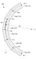
- FIG. 6 is a plan view showing a laminated body 100 in which a plurality of second composite sheets 120 are laminated on a plurality of first composite sheets 110.
- FIG. 7 is a partially enlarged view of the laminated body 100 shown in FIG.
- FIG. 8 is a plan view of the second composite sheet 120 shown in FIG. 7.
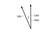
- FIG. 9 is a diagram showing the relationship between the second longitudinal LD2c of one adjacent second composite sheet 120c and the second longitudinal LD2d of the other second composite sheet 120d. Since the laminate 100 of the present embodiment is finally laminated in six layers, the laminate 100 shown in FIGS. 6 and 7 is at a stage before the lamination is completed.
- the laminated body 100 of the present embodiment has an end portion in the longitudinal direction (second longitudinal direction) of one adjacent second composite sheet 120 and a longitudinal direction (second longitudinal direction) of the other second composite sheet 120. 2
- the end portions in the longitudinal direction) are arranged close to each other in a state where they do not overlap with each other in the thickness direction (thickness direction TD shown in FIG. 12).
- the second composite sheet 120 is a sheet-like material containing a fiber base material (second fiber base material) and a resin material (second resin material).
- the plurality of second composite sheets 120 have the second composite sheet 120a, the second composite sheet 120b, and the second composite sheet 120b along the arrangement direction AD passing on the arc of the radius R1 centered on the point O.
- the two composite sheets 120c, the second composite sheet 120d, the second composite sheet 120e, and the second composite sheet 120f are arranged clockwise in this order.
- the plurality of second composite sheets 120 are arranged so that positions P21 to P27 are end positions (second end positions).
- the longitudinal ends of the second composite sheet 120a are located at positions P21 and P22
- the longitudinal ends of the second composite sheet 120b are located at positions P22 and P23
- the longitudinal ends of the second composite sheet 120c are arranged at positions P23 and P24.
- the longitudinal ends of the second composite sheet 120d are located at positions P24 and P25
- the longitudinal ends of the second composite sheet 120e are located at positions P25 and P26
- the longitudinal ends of the second composite sheet 120f The ends of the are arranged at positions P26 and P27.
- the plurality of positions P11 to P17 in the arrangement direction AD in which the ends of the plurality of first composite sheets 110 are arranged are the arrangement direction AD in which the ends of the plurality of second composite sheets 120 are arranged. It is a position different from the plurality of positions P21 to P27 in.
- the position of the second composite sheet 120 in the two layers is different from the position of the cut. Therefore, the strength of the structure manufactured from the laminated body 100 can be increased as compared with the case where these positions are matched.
- the second composite sheet 120c has a second longitudinal direction LD2c and a second lateral direction SD2c along the arrangement direction AD
- the second composite sheet 120d has a second longitudinal direction along the arrangement direction AD. It has a direction LD2d and a second lateral direction SD2d
- the second composite sheet 120e has a second longitudinal direction LD2e and a second lateral direction SD2e along the arrangement direction AD.
- the second composite sheet 120a, the second composite sheet 120b, the second composite sheet 120e, and the second composite sheet 120f also have a second longitudinal direction LD2 and a second lateral direction SD2.
- the second composite sheet 120d is on the other side of the second lateral SD2d than the length of the second longitudinal LD2d on one side of the second lateral SD2d (inner peripheral side with respect to the point O).
- the length of the second longitudinal direction LD2d at (the outer peripheral side with respect to the point O) is long and has a trapezoidal shape with equal legs.
- the other second composite sheet 120 (120a, 120b, 120c, 120e, 120f) has the same shape.
- the laminate 100 of the present embodiment has the edge of the second longitudinal LD2 of the other second composite sheet 120 adjacent to the edge of the second longitudinal LD2 of the second composite sheet 120 having a trapezoidal shape with equal legs. It is arranged without a gap along the arrangement direction AD so as to coincide with the position of the side of the portion.
- the line on the surface of the second composite sheet 120d shown in FIG. 8 indicates the fiber direction (second fiber direction FD2) in which the fiber base material contained in the second composite sheet 120d is oriented.
- the second fiber direction FD2d of the second composite sheet 120d is the same direction as the second longitudinal direction LD2d. That is, the angle (second predetermined angle) formed by the second fiber direction FD2d and the second longitudinal direction LD2d is 0 degrees.
- the second fiber direction FD2 of the second composite sheet 120 laminated to the second layer has an angle of 0 degrees with respect to the second longitudinal direction LD2, but other embodiments may also be used. good.
- the angle (second predetermined angle) formed by the second fiber direction FD2d and the second longitudinal direction LD2d of the second composite sheet 120 laminated in the second layer is arbitrary such as 90 degrees, 45 degrees, and ⁇ 45 degrees. It may be the direction of.
- each of the second composite sheet 120a, 120b, 120c, 120d, 120e, 120f is a second longitudinal LD2 of one adjacent second composite sheet 120 and the other second composite sheet 120. It is arranged along the curved arrangement direction AD so as to intersect with the second longitudinal direction LD2. As shown in FIGS. 7 and 9, for example, the second longitudinal LD2d of one adjacent second composite sheet 120d and the second longitudinal LD2c of the other second composite sheet 120c intersect at an intersection angle ⁇ . Is located in.
- the crossing angle ⁇ is the same as the crossing angle at which the first longitudinal LD1 of one adjacent first composite sheet 110 and the first longitudinal LD1 of the other first composite sheet 110 intersect in the first layer.
- FIG. 10 is a flowchart showing a stacking method of the present embodiment.
- the second layer (LY2 in FIG. 12) containing the plurality of second composite sheets 120 is laminated.
- a third layer (LY3 in FIG. 12) containing a plurality of third composite sheets is laminated on the second layer, and a fourth layer (LY4 in FIG. 12) containing a plurality of fourth composite sheets is laminated on the third layer.
- a fifth layer (LY5 in FIG. 12) containing a plurality of fifth composite sheets is laminated on the fourth layer, and a sixth layer (FIG. 12) containing a plurality of sixth composite sheets is laminated on the fifth layer. 12 LY6) are laminated.
- FIG. 11 is a plan view showing a laminated body 100 in which a plurality of sixth composite sheets 160 of the sixth layer are laminated.
- FIG. 12 is a cross-sectional view taken along the line AA of the laminated body shown in FIG. In FIG. 11, the fiber direction of the plurality of sixth composite sheets 160 is not shown.
- the plurality of second composite sheets 120 have the second composite sheet 120a, the second composite sheet 120b, and the second composite sheet 120b along the arrangement direction AD passing on the arc of the radius R1 centered on the point O.
- the two composite sheets 120c, the second composite sheet 120d, the second composite sheet 120e, and the second composite sheet 120f are arranged clockwise in this order.
- each of the plurality of third composite sheets 130, the plurality of fourth composite sheets 140, the plurality of fifth composite sheets 150, and the plurality of sixth composite sheets 160 has a radius R1 centered on the point O. It is arranged clockwise along the arrangement direction AD passing on the arc of.
- the first composite sheet 110, the second composite sheet 120, the third composite sheet 130, and the fourth composite sheet are not shown.
- the plurality of sixth composite sheets 160 are arranged so that positions P61 to P67 are end positions.
- the longitudinal ends of the sixth composite sheet 160a are located at positions P61 and P62
- the longitudinal ends of the sixth composite sheet 160b are located at positions P62 and P63
- the longitudinal ends of the sixth composite sheet 160c are located at positions P63 and P64.
- the longitudinal ends of the sixth composite sheet 160d are located at positions P64 and P65
- the longitudinal ends of the sixth composite sheet 160e are located at positions P65 and P66
- the longitudinal ends of the sixth composite sheet 160f The ends of the are arranged at positions P66 and P67.
- a plurality of first end positions (for example, positions P14) in the arrangement direction AD in which the ends of the plurality of first composite sheets 110 are arranged are a plurality of second composites.
- the position is different from the plurality of second end positions (for example, position P24) in the arrangement direction AD in which the end of the sheet 120 is arranged.
- the end positions of adjacent layers in the thickness direction TD are different positions.
- the end position P24 of the second composite sheet 120 of the second layer LY2 is the end position P14 of the first composite sheet 110 of the first layer LY1 and the third layer LY3 in the arrangement direction AD.
- the position is different from the end position P34 of the third composite sheet 130.
- the end position P44 of the fourth composite sheet 140 of the fourth layer LY4 is the end position P34 of the third composite sheet 130 of the third layer LY3 and the fifth composite sheet of the fifth layer LY5 in the arrangement direction AD. It is a position different from the end position P54 of 150.
- the end position P64 of the sixth layer LY6 is a position different from the end position P54 of the fifth composite sheet 150 of the fifth layer LY5 in the arrangement direction AD.
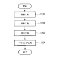
- FIG. 13 is a flowchart showing a method for manufacturing the composite material of the present embodiment.
- step S201 the laminating step described in steps S101 to S104 of FIG. 10 is executed.
- step S202 the laminated body 100 laminated in the laminating step is shaped by using a shaping device (not shown) so that the cross-sectional view of the plane orthogonal to the arrangement direction AD is Z-shaped.
- the shaping device shapes the mountain fold so that the bending angle is 90 degrees along the mountain fold line MF shown in FIG. 11, and the bending angle is along the valley fold line VF shown in FIG. Is shaped into a valley fold so that is 90 degrees.
- the mountain fold line MF is a line passing on an arc having a radius R2 centered on the point O, and the radius R2 is smaller than the radius R1.
- the valley fold line VF is a line passing on an arc having a radius R3 centered on the point O, and the radius R3 is larger than the radius R1.
- step S203 a curing step of curing the composite sheet constituting the laminated body 100 is executed.
- the resin material contained in the composite sheet is a thermosetting resin
- the thermosetting resin is cured by heating the laminate 100 shaped in step S202 in an autoclave.
- the resin material contained in the composite sheet is a thermoplastic resin
- the laminate 100 shaped in the state of being heated in step S202 is cooled to cure the thermoplastic resin.
- step S204 the end portion of the laminated body 100 in the width direction is trimmed (cut) to adjust the shape of the laminated body 100.
- the inner laminate 100 of the inner trimming line TR1 shown in FIG. 11 is cut off by a trimming device (not shown) such as a water jet cutter, and the outer laminate 100 of the outer trimming line TR2 shown in FIG. 11 is cut off. Is excised.
- the inner trimming line TR1 is a line passing on an arc having a radius R4 centered on the point O, and the radius R4 is smaller than the radius R2.
- the outer trimming line TR2 is a line passing on an arc having a radius R5 centered on the point O, and the radius R5 is larger than the radius R3.
- each of the plurality of first composite sheets 110 constituting the first layer LY1 has a first longitudinal direction LD1 and a first lateral direction SD1.
- the first fiber direction FD1 of each of the plurality of first composite sheets 110 constituting the first layer LY1 has a first predetermined angle ⁇ with respect to the first longitudinal direction LD1.
- each of the plurality of second composite sheets 120 constituting the second layer LY2 has a second longitudinal direction LD2 and a second lateral direction SD2.
- the second fiber direction FD2 of each of the plurality of second composite sheets 120 constituting the second layer LY2 has a second predetermined angle with respect to the second longitudinal direction LD2.
- the first predetermined angle ⁇ and the second predetermined angle are, for example, any of 0 degrees, 90 degrees, 45 degrees, ⁇ 45 degrees, and the like.
- the plurality of first composite sheets 110 are the end portion of the first longitudinal LD1c of one adjacent first composite sheet 110c and the first longitudinal of the other first composite sheet 110d.
- the end portions of the direction LD1d are arranged so as to be close to each other so as not to overlap the thickness direction TD.
- the thickness of the end portion of the second longitudinal direction LD2c of one adjacent second composite sheet 120c and the end portion of the second longitudinal direction LD2d of the other second composite sheet 120d are thick. They are arranged in close proximity to each other without overlapping the direction TD. Since the laminate 100 is formed by arranging the plurality of first composite sheets 110 and the plurality of second composite sheets 120 in close proximity to each other, unnecessary parts are not generated during manufacturing, and the manufacturing cost can be reduced. can.
- the curved arrangement direction AD so that the first longitudinal LD1c of one first composite sheet 110c and the first longitudinal LD1d of the other first composite sheet 110d intersect. It is arranged along. Further, it is arranged along the curved arrangement direction AD so that the second longitudinal direction LD2c of one second composite sheet 120c and the second longitudinal direction LD2d of the other second composite sheet 120d intersect.
- the first composite sheet 110 is oriented along the curved arrangement direction as a whole while the first fiber base material is oriented in the first fiber direction FD1 without causing in-plane deformation. Be placed.
- the second fiber base material is oriented in the second fiber direction FD2 without causing in-plane deformation, and the second composite sheet is aligned along the curved arrangement direction AD as a whole. 120 is arranged. Since neither the first composite sheet 110 nor the second composite sheet 120 undergoes in-plane deformation, the production quality of the laminated body 100 can be improved.
- the crossing angle ⁇ at which the first longitudinal LD1c of one first composite sheet 110c and the first longitudinal LD1d of the other first composite sheet 110d intersect is 30 degrees or less. ..
- the crossing angle ⁇ is set to 30 degrees or less, the approximation of the first longitudinal direction LD1 to the curved arrangement direction AD and the manufacturing quality of the laminated body 100 associated therewith can be improved.
- the plurality of first end position positions P11 to P17 in the arrangement direction AD in which the ends of the plurality of first composite sheets 110 are arranged are the ends of the plurality of second composite sheets 120. Is a position different from the plurality of second end positions P21 to P27 in the arrangement direction AD in which the is arranged.
- the laminated body 100 according to the present embodiment by making the first end position and the second end position different, the laminated body is more than the case where the first end position and the second end position match.
- the strength of the structure obtained by curing 100 can be increased. That is, it is possible to suppress cracks and breaks that may occur when the first end position and the second end position coincide with each other.
- the laminate described in the embodiment described above is grasped as follows, for example.
- the laminate (100) according to the present disclosure is a first fiber having a first longitudinal direction (LD1) and a first lateral direction (SD1) and having a first predetermined angle ( ⁇ 1) with respect to the first longitudinal direction. It has a plurality of first composite sheets (110) including a first fiber base material and a first resin material oriented in the direction (FD1), and a second longitudinal direction (LD2) and a second lateral direction (SD2).
- a plurality of second composite sheets (120) containing a second fiber base material and a second resin material oriented in the second fiber direction (FD2) having a second predetermined angle with respect to the second longitudinal direction.
- the second layer (LY2) including the second composite sheet is laminated in a state of being in contact with the first layer (LY1) containing the first composite sheet, and the first In the composite sheet, the end portion of the first composite sheet adjacent to each other in the first longitudinal direction and the end portion of the other first composite sheet in the first longitudinal direction do not overlap in the thickness direction (TD). They are arranged along a curved arrangement direction (AD) so as to be close to each other in a state and intersect the longitudinal direction of one of the first composite sheets and the first longitudinal direction of the first composite sheet of the other. In the plurality of the second composite sheets, the end portion of the second composite sheet adjacent to each other in the second longitudinal direction and the end portion of the other second composite sheet in the second longitudinal direction are described. Along the arrangement direction so that they are close to each other in a non-overlapping state in the thickness direction, and the second longitudinal direction of one of the second composite sheets intersects with the second longitudinal direction of the second composite sheet of the other. Are arranged.
- each of the plurality of first composite sheets constituting the first layer has a first longitudinal direction and a first lateral direction. Further, the first fiber direction of each of the plurality of first composite sheets constituting the first layer has a first predetermined angle with respect to the first longitudinal direction. Similarly, each of the plurality of second composite sheets constituting the second layer has a second longitudinal direction and a second lateral direction. Further, the second fiber direction of each of the plurality of second composite sheets constituting the second layer has a second predetermined angle with respect to the second longitudinal direction.
- the first predetermined angle and the second predetermined angle are, for example, any of 0 degrees, 90 degrees, 45 degrees, ⁇ 45 degrees, and the like.
- the plurality of first composite sheets include an end portion of one adjacent first composite sheet in the first longitudinal direction and an end portion of the other first composite sheet in the first longitudinal direction. Are arranged in close proximity without overlapping in the thickness direction. Further, in the plurality of second composite sheets, the end portion of one adjacent second composite sheet in the second longitudinal direction and the end portion of the other second composite sheet in the second longitudinal direction do not overlap in the thickness direction. They are placed in close proximity to each other. Since the laminated body is formed by arranging a plurality of first composite sheets and a plurality of second composite sheets in close proximity to each other, unnecessary portions are not generated during manufacturing, and the manufacturing cost can be reduced.
- the laminate according to the present disclosure are arranged along a curved arrangement direction so that the first longitudinal direction of one first composite sheet and the first longitudinal direction of the other first composite sheet intersect. There is. Further, they are arranged along a curved arrangement direction so that the second longitudinal direction of one second composite sheet and the second longitudinal direction of the other second composite sheet intersect. Therefore, in each first composite sheet, the first composite sheet is arranged along the curved arrangement direction as a whole while orienting the first fiber base material in the direction of the first fiber without causing in-plane deformation. ..
- the second composite sheet is arranged along the curved arrangement direction as a whole while orienting the second fiber base material in the direction of the second fiber without causing in-plane deformation. NS. Since neither the first composite sheet nor the second composite sheet undergoes in-plane deformation, the production quality of the laminated body can be improved.
- the arrangement direction is a direction extending along a curve that bends in a certain direction. According to the laminate according to the present disclosure, even when the first composite sheet and the second composite sheet are arranged along the arrangement direction extending along a curve that bends in a certain direction, the first composite sheet and the second composite sheet are arranged.
- the composite sheet can be arranged appropriately to improve the manufacturing quality.
- the crossing angle ( ⁇ ) at which the first longitudinal direction of one of the first composite sheets and the first longitudinal direction of the other first composite sheet intersect is 30 degrees or less. be. By setting the crossing angle to 30 degrees or less, it is possible to improve the approximation of the first longitudinal direction with respect to the curved arrangement direction of the plurality of first composite sheets and the manufacturing quality of the laminated body accompanying the approximation.
- the crossing angle ( ⁇ ) at which the second longitudinal direction of one of the second composite sheets and the second longitudinal direction of the second composite sheet of the other intersect is 30 degrees or less. be. By setting the crossing angle to 30 degrees or less, it is possible to improve the approximation of the second longitudinal direction to the curved arrangement direction of the plurality of second composite sheets and the manufacturing quality of the laminated body accompanying the approximation.
- a plurality of first end position positions (P11 to P17) where the end portions of the first composite sheet are arranged and the end portions of the second composite sheet are arranged.
- the plurality of second end positions (P21 to P27) are different positions in the arrangement direction.
- the first end position and the second end position are more laminated than when they coincide with each other. It is possible to increase the strength of the structure in which the body is hardened. That is, it is possible to suppress cracks and breaks that may occur when the first end position and the second end position coincide with each other in the arrangement direction.
- the laminating method described in the above-described embodiment can be grasped as follows, for example.
- the laminating method according to the present disclosure is a laminating method in which a second layer containing a plurality of second composite sheets is laminated in a state of being in contact with a first layer containing a plurality of first composite sheets, and the first composite sheet is laminated.
- the second composite sheet is formed in a sheet shape and is oriented in the second fiber direction having a second longitudinal direction and a second lateral direction and a second predetermined angle with respect to the second longitudinal direction.
- the first composite sheet is formed in the form of a sheet containing a fiber base material and a second resin material, and a plurality of the first composite sheets are placed on one adjacent first composite sheet at the end in the first longitudinal direction and the other first composite sheet.
- the first of the first composite sheet in the first longitudinal direction and the other of the first composite sheet which are close to each other in a state where the ends in the first longitudinal direction of the composite sheet do not overlap each other in the thickness direction.
- the ends of the second composite sheet in the second longitudinal direction are close to each other in a non-overlapping state in the thickness direction, and the second composite sheet of one of the second composite sheets and the second composite of the other.
- a second laminating step of arranging the sheets along the arrangement direction so as to intersect the second longitudinal direction of the sheets is provided.
- the plurality of first composite sheets are formed by the first laminating step, the end portion in the first longitudinal direction of one adjacent first composite sheet and the first of the other first composite sheet. It is arranged in a state of being close to each other so that the ends in the longitudinal direction do not overlap with each other in the thickness direction. Further, in the plurality of second composite sheets, the thickness of the end portion of one adjacent second composite sheet in the second longitudinal direction and the end portion of the other second composite sheet in the second longitudinal direction are thickened by the second laminating step. They are arranged in close proximity without overlapping in the vertical direction. In the first laminating step and the second laminating step, since the plurality of first composite sheets and the plurality of second composite sheets are arranged in close proximity to each other, unnecessary parts are not generated during manufacturing, and the manufacturing cost is reduced. Can be done.
- the laminating method in the first laminating step, a curved arrangement direction so that the first longitudinal direction of one first composite sheet and the first longitudinal direction of the other first composite sheet intersect. It is placed along. Further, by the second laminating step, the second composite sheet is arranged along the curved arrangement direction so as to intersect the second longitudinal direction of the second composite sheet and the second longitudinal direction of the other second composite sheet. Therefore, in each first composite sheet, the first composite sheet is arranged along the curved arrangement direction as a whole while orienting the first fiber base material in the direction of the first fiber without causing in-plane deformation. ..
- the second composite sheet is arranged along the curved arrangement direction as a whole while orienting the second fiber base material in the direction of the second fiber without causing in-plane deformation. NS. Since neither the first composite sheet nor the second composite sheet undergoes in-plane deformation, the production quality of the laminated body can be improved.
- the arrangement direction is a direction extending along a curve that bends in a certain direction. According to the laminating method according to the present disclosure, even when the first composite sheet and the second composite sheet are arranged along the arrangement direction extending along a curve that bends in a certain direction, the first composite sheet and the second composite sheet are arranged.
- the composite sheet can be arranged appropriately to improve the manufacturing quality.
- the crossing angle ( ⁇ ) at which the first longitudinal direction of one of the first composite sheets and the first longitudinal direction of the other first composite sheet intersect is 30 degrees or less. be. By setting the crossing angle to 30 degrees or less, it is possible to improve the approximation of the first longitudinal direction with respect to the curved arrangement direction of the plurality of first composite sheets and the manufacturing quality of the laminated body accompanying the approximation.
- the crossing angle ( ⁇ ) at which the second longitudinal direction of one of the second composite sheets and the second longitudinal direction of the second composite sheet of the other intersect is 30 degrees or less. be.
- a plurality of first end position positions (P11 to P17) where the end portions of the first composite sheet are arranged and the end portions of the second composite sheet are arranged.
- the plurality of second end positions (P21 to P27) are different positions in the arrangement direction.
- the laminating method according to the present disclosure by making the first end position and the second end position different in the arrangement direction, the laminating is performed more than when the first end position and the second end position coincide with each other. It is possible to increase the strength of the structure in which the body is hardened. That is, it is possible to suppress cracks and breaks that may occur when the first end position and the second end position coincide with each other in the arrangement direction.
Landscapes
- Engineering & Computer Science (AREA)
- Chemical & Material Sciences (AREA)
- Composite Materials (AREA)
- Mechanical Engineering (AREA)
- Textile Engineering (AREA)
- Laminated Bodies (AREA)
- Moulding By Coating Moulds (AREA)
Priority Applications (4)
| Application Number | Priority Date | Filing Date | Title |
|---|---|---|---|
| EP20921415.4A EP4082769B1 (en) | 2020-02-28 | 2020-02-28 | Layered body and layering method |
| PCT/JP2020/008205 WO2021171529A1 (ja) | 2020-02-28 | 2020-02-28 | 積層体および積層方法 |
| US17/795,739 US12570070B2 (en) | 2020-02-28 | 2020-02-28 | Layered body and layering method |
| JP2022502752A JP7404499B2 (ja) | 2020-02-28 | 2020-02-28 | 積層体および複合材製造方法 |
Applications Claiming Priority (1)
| Application Number | Priority Date | Filing Date | Title |
|---|---|---|---|
| PCT/JP2020/008205 WO2021171529A1 (ja) | 2020-02-28 | 2020-02-28 | 積層体および積層方法 |
Publications (1)
| Publication Number | Publication Date |
|---|---|
| WO2021171529A1 true WO2021171529A1 (ja) | 2021-09-02 |
Family
ID=77491159
Family Applications (1)
| Application Number | Title | Priority Date | Filing Date |
|---|---|---|---|
| PCT/JP2020/008205 Ceased WO2021171529A1 (ja) | 2020-02-28 | 2020-02-28 | 積層体および積層方法 |
Country Status (4)
| Country | Link |
|---|---|
| US (1) | US12570070B2 (https=) |
| EP (1) | EP4082769B1 (https=) |
| JP (1) | JP7404499B2 (https=) |
| WO (1) | WO2021171529A1 (https=) |
Citations (8)
| Publication number | Priority date | Publication date | Assignee | Title |
|---|---|---|---|---|
| US5394906A (en) * | 1993-02-10 | 1995-03-07 | The United States Of America As Represented By The Administrator Of The National Aeronautics And Space Administration | Method and apparatus for weaving curved material preforms |
| JP2008540168A (ja) * | 2005-05-03 | 2008-11-20 | ザ・ボーイング・カンパニー | 湾曲した複合構造要素の製造方法 |
| US20090317585A1 (en) * | 2003-03-06 | 2009-12-24 | Anton Bech | Method for preparing pre-form materials |
| JP2010150685A (ja) * | 2008-12-24 | 2010-07-08 | Toray Ind Inc | 湾曲形状強化繊維基材、およびそれを用いた積層体、プリフォーム、繊維強化樹脂複合材料とそれらの製造方法 |
| WO2010087443A1 (ja) * | 2009-02-02 | 2010-08-05 | 東レ株式会社 | 円弧状部を有する帯状強化繊維基材の製造方法および製造装置、およびその基材を用いた積層体、プリフォームおよび繊維強化樹脂複合材料 |
| JP2011255533A (ja) * | 2010-06-07 | 2011-12-22 | Toray Ind Inc | 湾曲形状を有する繊維強化プラスチック成形品 |
| JP2014504566A (ja) * | 2011-01-25 | 2014-02-24 | ザ・ボーイング・カンパニー | 起伏のある複合構造物を製造するための方法および装置ならびにそれにより製造される構造物 |
| US9102103B2 (en) | 2006-02-02 | 2015-08-11 | The Boeing Company | Thermoplastic composite parts having integrated metal fittings and method of making the same |
Family Cites Families (5)
| Publication number | Priority date | Publication date | Assignee | Title |
|---|---|---|---|---|
| US7469735B2 (en) | 2005-08-03 | 2008-12-30 | The Boeing Corporation | Composite structural element fabricating device and method |
| EP2047971B1 (en) * | 2007-10-09 | 2013-12-04 | Saab Ab | Method for manufacturing beams of fiber-reinforced composite material |
| CA2711928A1 (en) | 2008-01-11 | 2009-07-16 | Tomoyuki Shinoda | Reinforcing fiber substrate of curved shape, layered product using the same, preform, fiber-reinforced resin composite material, and processes for producing those |
| JP6033730B2 (ja) * | 2013-04-16 | 2016-11-30 | 本田技研工業株式会社 | 繊維シート積層体の製造方法及び製造装置 |
| CN111565920A (zh) * | 2017-08-28 | 2020-08-21 | 伟博工业公司 | 热塑性复合母片和带以及方法 |
-
2020
- 2020-02-28 EP EP20921415.4A patent/EP4082769B1/en active Active
- 2020-02-28 US US17/795,739 patent/US12570070B2/en active Active
- 2020-02-28 JP JP2022502752A patent/JP7404499B2/ja active Active
- 2020-02-28 WO PCT/JP2020/008205 patent/WO2021171529A1/ja not_active Ceased
Patent Citations (8)
| Publication number | Priority date | Publication date | Assignee | Title |
|---|---|---|---|---|
| US5394906A (en) * | 1993-02-10 | 1995-03-07 | The United States Of America As Represented By The Administrator Of The National Aeronautics And Space Administration | Method and apparatus for weaving curved material preforms |
| US20090317585A1 (en) * | 2003-03-06 | 2009-12-24 | Anton Bech | Method for preparing pre-form materials |
| JP2008540168A (ja) * | 2005-05-03 | 2008-11-20 | ザ・ボーイング・カンパニー | 湾曲した複合構造要素の製造方法 |
| US9102103B2 (en) | 2006-02-02 | 2015-08-11 | The Boeing Company | Thermoplastic composite parts having integrated metal fittings and method of making the same |
| JP2010150685A (ja) * | 2008-12-24 | 2010-07-08 | Toray Ind Inc | 湾曲形状強化繊維基材、およびそれを用いた積層体、プリフォーム、繊維強化樹脂複合材料とそれらの製造方法 |
| WO2010087443A1 (ja) * | 2009-02-02 | 2010-08-05 | 東レ株式会社 | 円弧状部を有する帯状強化繊維基材の製造方法および製造装置、およびその基材を用いた積層体、プリフォームおよび繊維強化樹脂複合材料 |
| JP2011255533A (ja) * | 2010-06-07 | 2011-12-22 | Toray Ind Inc | 湾曲形状を有する繊維強化プラスチック成形品 |
| JP2014504566A (ja) * | 2011-01-25 | 2014-02-24 | ザ・ボーイング・カンパニー | 起伏のある複合構造物を製造するための方法および装置ならびにそれにより製造される構造物 |
Non-Patent Citations (1)
| Title |
|---|
| See also references of EP4082769A4 |
Also Published As
| Publication number | Publication date |
|---|---|
| JPWO2021171529A1 (https=) | 2021-09-02 |
| EP4082769A1 (en) | 2022-11-02 |
| US20230064511A1 (en) | 2023-03-02 |
| US12570070B2 (en) | 2026-03-10 |
| EP4082769A4 (en) | 2023-04-12 |
| JP7404499B2 (ja) | 2023-12-25 |
| EP4082769B1 (en) | 2024-02-21 |
Similar Documents
| Publication | Publication Date | Title |
|---|---|---|
| US8789275B2 (en) | Wind turbine blade and method of manufacturing wind turbine blade | |
| CN102548741B (zh) | 使用预堆叠的多方向连续纤维叠层模制复杂复合部件的方法 | |
| JP6781676B2 (ja) | 成形遮音構造形成方法 | |
| KR101353112B1 (ko) | 복합재 부재의 제조 방법 및 프리프레그 시트의 적층체 | |
| JP6110914B2 (ja) | 複合材構造体及び複合材構造体の製造方法 | |
| JP5078757B2 (ja) | 風車翼及び風車翼の製造方法 | |
| JP7412458B2 (ja) | 複合材構造体の製造方法及び積層体の製造方法並びに積層体及び積層型 | |
| US12226986B2 (en) | Core material and structure | |
| WO2021171529A1 (ja) | 積層体および積層方法 | |
| JP4752613B2 (ja) | 積層部品の製造方法 | |
| JP5180606B2 (ja) | 複合材部材の製造方法及びプリプレグシートの積層体 | |
| EP2522495B1 (en) | Structural member with flange having a clean cut edge, and process for the manufacture thereof | |
| CN110290919A (zh) | 复合材料及复合材料的制造方法 | |
| JP2025116355A (ja) | 格子状構造体および格子状構造体の製造方法 | |
| JP7210805B2 (ja) | 支持体および支持体取付方法 | |
| WO2018008689A1 (ja) | 複合材料の基材、引抜成形材料、複合材料の基材の製造方法及び引抜成形材料の製造方法 | |
| US12496786B2 (en) | Forming method | |
| JPWO2021171529A5 (https=) | ||
| JP7536568B2 (ja) | 成形体およびその製造方法 | |
| JP3683415B2 (ja) | 繊維強化プラスチック製のハニカムコア | |
| WO2025074697A1 (ja) | 接合方法および接合構造体 | |
| WO2024232109A1 (ja) | 賦形装置および賦形方法 | |
| JP2023157639A (ja) | 積層体及び賦形方法 | |
| JP2017124570A (ja) | 湾曲形状繊維積層体の製造方法および装置 | |
| CN116408988A (zh) | 高尔夫球杆的碳片部件的自动化制造方法 |
Legal Events
| Date | Code | Title | Description |
|---|---|---|---|
| 121 | Ep: the epo has been informed by wipo that ep was designated in this application |
Ref document number: 20921415 Country of ref document: EP Kind code of ref document: A1 |
|
| ENP | Entry into the national phase |
Ref document number: 2022502752 Country of ref document: JP Kind code of ref document: A |
|
| ENP | Entry into the national phase |
Ref document number: 2020921415 Country of ref document: EP Effective date: 20220727 |
|
| NENP | Non-entry into the national phase |
Ref country code: DE |
|
| WWG | Wipo information: grant in national office |
Ref document number: 17795739 Country of ref document: US |