WO2021171338A1 - 移動対象追跡装置、移動対象追跡方法、移動対象追跡システム、および、学習装置、並びに、プログラム - Google Patents
移動対象追跡装置、移動対象追跡方法、移動対象追跡システム、および、学習装置、並びに、プログラム Download PDFInfo
- Publication number
- WO2021171338A1 WO2021171338A1 PCT/JP2020/007345 JP2020007345W WO2021171338A1 WO 2021171338 A1 WO2021171338 A1 WO 2021171338A1 JP 2020007345 W JP2020007345 W JP 2020007345W WO 2021171338 A1 WO2021171338 A1 WO 2021171338A1
- Authority
- WO
- WIPO (PCT)
- Prior art keywords
- camera
- tracking
- information
- swing
- moving object
- Prior art date
- Legal status (The legal status is an assumption and is not a legal conclusion. Google has not performed a legal analysis and makes no representation as to the accuracy of the status listed.)
- Ceased
Links
Images






Classifications
-
- G—PHYSICS
- G06—COMPUTING OR CALCULATING; COUNTING
- G06T—IMAGE DATA PROCESSING OR GENERATION, IN GENERAL
- G06T7/00—Image analysis
- G06T7/20—Analysis of motion
- G06T7/292—Multi-camera tracking
-
- H—ELECTRICITY
- H04—ELECTRIC COMMUNICATION TECHNIQUE
- H04N—PICTORIAL COMMUNICATION, e.g. TELEVISION
- H04N23/00—Cameras or camera modules comprising electronic image sensors; Control thereof
- H04N23/90—Arrangement of cameras or camera modules, e.g. multiple cameras in TV studios or sports stadiums
-
- G—PHYSICS
- G03—PHOTOGRAPHY; CINEMATOGRAPHY; ANALOGOUS TECHNIQUES USING WAVES OTHER THAN OPTICAL WAVES; ELECTROGRAPHY; HOLOGRAPHY
- G03B—APPARATUS OR ARRANGEMENTS FOR TAKING PHOTOGRAPHS OR FOR PROJECTING OR VIEWING THEM; APPARATUS OR ARRANGEMENTS EMPLOYING ANALOGOUS TECHNIQUES USING WAVES OTHER THAN OPTICAL WAVES; ACCESSORIES THEREFOR
- G03B15/00—Special procedures for taking photographs; Apparatus therefor
-
- G—PHYSICS
- G03—PHOTOGRAPHY; CINEMATOGRAPHY; ANALOGOUS TECHNIQUES USING WAVES OTHER THAN OPTICAL WAVES; ELECTROGRAPHY; HOLOGRAPHY
- G03B—APPARATUS OR ARRANGEMENTS FOR TAKING PHOTOGRAPHS OR FOR PROJECTING OR VIEWING THEM; APPARATUS OR ARRANGEMENTS EMPLOYING ANALOGOUS TECHNIQUES USING WAVES OTHER THAN OPTICAL WAVES; ACCESSORIES THEREFOR
- G03B17/00—Details of cameras or camera bodies; Accessories therefor
-
- G—PHYSICS
- G08—SIGNALLING
- G08G—TRAFFIC CONTROL SYSTEMS
- G08G1/00—Traffic control systems for road vehicles
-
- G—PHYSICS
- G08—SIGNALLING
- G08G—TRAFFIC CONTROL SYSTEMS
- G08G1/00—Traffic control systems for road vehicles
- G08G1/01—Detecting movement of traffic to be counted or controlled
- G08G1/04—Detecting movement of traffic to be counted or controlled using optical or ultrasonic detectors
-
- H—ELECTRICITY
- H04—ELECTRIC COMMUNICATION TECHNIQUE
- H04N—PICTORIAL COMMUNICATION, e.g. TELEVISION
- H04N23/00—Cameras or camera modules comprising electronic image sensors; Control thereof
- H04N23/60—Control of cameras or camera modules
- H04N23/61—Control of cameras or camera modules based on recognised objects
-
- H—ELECTRICITY
- H04—ELECTRIC COMMUNICATION TECHNIQUE
- H04N—PICTORIAL COMMUNICATION, e.g. TELEVISION
- H04N23/00—Cameras or camera modules comprising electronic image sensors; Control thereof
- H04N23/60—Control of cameras or camera modules
- H04N23/617—Upgrading or updating of programs or applications for camera control
-
- H—ELECTRICITY
- H04—ELECTRIC COMMUNICATION TECHNIQUE
- H04N—PICTORIAL COMMUNICATION, e.g. TELEVISION
- H04N23/00—Cameras or camera modules comprising electronic image sensors; Control thereof
- H04N23/60—Control of cameras or camera modules
- H04N23/66—Remote control of cameras or camera parts, e.g. by remote control devices
- H04N23/661—Transmitting camera control signals through networks, e.g. control via the Internet
-
- H—ELECTRICITY
- H04—ELECTRIC COMMUNICATION TECHNIQUE
- H04N—PICTORIAL COMMUNICATION, e.g. TELEVISION
- H04N23/00—Cameras or camera modules comprising electronic image sensors; Control thereof
- H04N23/60—Control of cameras or camera modules
- H04N23/695—Control of camera direction for changing a field of view, e.g. pan, tilt or based on tracking of objects
-
- H—ELECTRICITY
- H04—ELECTRIC COMMUNICATION TECHNIQUE
- H04N—PICTORIAL COMMUNICATION, e.g. TELEVISION
- H04N7/00—Television systems
- H04N7/18—Closed-circuit television [CCTV] systems, i.e. systems in which the video signal is not broadcast
-
- G—PHYSICS
- G06—COMPUTING OR CALCULATING; COUNTING
- G06T—IMAGE DATA PROCESSING OR GENERATION, IN GENERAL
- G06T2207/00—Indexing scheme for image analysis or image enhancement
- G06T2207/20—Special algorithmic details
- G06T2207/20081—Training; Learning
-
- G—PHYSICS
- G06—COMPUTING OR CALCULATING; COUNTING
- G06T—IMAGE DATA PROCESSING OR GENERATION, IN GENERAL
- G06T2207/00—Indexing scheme for image analysis or image enhancement
- G06T2207/20—Special algorithmic details
- G06T2207/20084—Artificial neural networks [ANN]
-
- G—PHYSICS
- G06—COMPUTING OR CALCULATING; COUNTING
- G06T—IMAGE DATA PROCESSING OR GENERATION, IN GENERAL
- G06T2207/00—Indexing scheme for image analysis or image enhancement
- G06T2207/30—Subject of image; Context of image processing
- G06T2207/30236—Traffic on road, railway or crossing
-
- G—PHYSICS
- G06—COMPUTING OR CALCULATING; COUNTING
- G06T—IMAGE DATA PROCESSING OR GENERATION, IN GENERAL
- G06T2207/00—Indexing scheme for image analysis or image enhancement
- G06T2207/30—Subject of image; Context of image processing
- G06T2207/30244—Camera pose
Definitions
- the present invention relates to a moving object tracking device, a moving object tracking method, a moving object tracking system, a learning device, and a program that control coordinated monitoring of a moving object by a plurality of camera devices.
- Non-Patent Document 1 a technology that automatically detects a target vehicle (tracking target) on a highway or the like and constantly captures the target vehicle while switching cameras around the vehicle has been put into practical use.
- the traveling direction of the target vehicle is predicted, and the camera in the traveling direction prepares to capture the vehicle, so that the target vehicle is continuously tracked between the cameras (see, for example, Non-Patent Document 1).
- the present invention has been made in view of such a point, and an object of the present invention is to control a plurality of camera devices to coordinately and autonomously track a moving object whose speed is changed.
- the moving object tracking device is a moving object tracking device that tracks a moving object by controlling a camera device group, and the camera device group is a reference camera that fixes the camera and captures the moving object.
- the moving target tracking device is composed of a swing camera that follows the movement of the moving target and takes a picture, and the moving target tracking device captures and advances the moving target that has passed in the tracking section for tracking the moving target.
- a position information creating unit that creates camera position information indicating the adjacency relationship between the plurality of reference cameras and the plurality of swinging cameras using directions, and an image from the reference camera is acquired to obtain the speed of the moving target and the speed of the moving target.
- any one of the plurality of swing cameras could capture the moving target in the entire tracking section.
- the tracking score calculation unit that calculates the tracking score, which is an evaluation value indicated by a ratio, and the running information are input, the rotation direction of the swing camera, the designated angle at the start of tracking, and the rotation direction of each of the swing cameras. It has a learning device that outputs a control value including a rotation start time from when the specified angle is set to rotation, and obtains the tracking score as a control result of each swing camera by the control value obtained from the learning device.
- the machine learning unit that acquires and stores the control value of each swing camera and the tracking score as the actual information in the storage unit in association with the driving information and the driving information from the reference camera are acquired, the actual information is obtained. It is characterized by having a control information creation unit that acquires control values of each swing camera corresponding to a tracking score that is equal to or higher than a predetermined value, creates control information, and transmits the control information to each swing camera. do.
- the present embodiment a mode for carrying out the present invention (hereinafter, referred to as "the present embodiment") will be described. First, an outline of the present invention will be described.
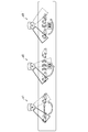
- a plurality of camera devices (hereinafter, may be simply referred to as “cameras”) are coordinated so as to appropriately capture the target vehicle (moving target) according to the installation environment. I could't control it.
- the speed is changed due to acceleration or deceleration, it is not possible to detect it and autonomously perform control such that the camera in the traveling direction of the vehicle follows the speed.
- the speed can be followed if there is no change (see reference numeral a1).
- the target vehicle accelerated or decelerated it could not follow (see reference numerals a2 and a3).
- the moving object tracking device 1 operates so as to follow the vehicle in the traveling direction of the vehicle with a camera (fixed camera) that detects the speed even if the speed is changed due to acceleration or deceleration. It controls to track the target vehicle autonomously in cooperation with the camera.
- a camera fixed camera
- a reference camera 51 fixed camera
- a swing camera 52 adjacent camera
- the moving target tracking device 1 sets the information of the optimum control value (for example, the rotation direction, the designated angle, the rotation start time) by using the information of the speed and the traveling direction detected by the reference camera 51 (fixed camera).
- the subsequent swing camera 52 in the traveling direction of the vehicle is controlled.
- the target vehicle can be tracked even when the speed is changed due to acceleration or deceleration (see reference numerals b1 and b2).
- the moving target tracking device 1 calculates this optimum control value by a method using machine learning (“learning phase” using the learning device 100 (learning device) described later). At that time, the moving target tracking device 1 is arranged at the start point and the end point on the road through which the target vehicle passes, instead of individually optimizing the control of each of the plurality of cameras (swinging cameras 52) that track the target vehicle. It is characterized in that learning is performed by optimizing so that the score related to vehicle tracking (“tracking score” described later) is higher in the entire camera (swing camera 52).
- the moving object tracking system 1000 including the moving object tracking device 1 according to the present embodiment has a plurality of camera devices (reference camera 51 and swing camera) located between the start point and the end point (tracking section). 52) can be linked to set and control the optimum control value as a whole in the tracking section for each swing camera 52.
- the moving object tracking system 1000 including the moving object tracking device 1 according to the present embodiment will be described in detail.
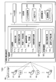
- FIG. 3 is a diagram showing the overall configuration of the moving object tracking system 1000 including the moving object tracking device 1 according to the present embodiment.
- the moving target tracking system 1000 includes a camera device group 50 having a plurality of reference cameras 51 for detecting the speed and traveling direction of the target vehicle (moving target), a swing camera 52 for tracking and taking a picture of the target vehicle, and a camera. It is provided with a moving target tracking device 1 that is communicatively connected to each camera device of the device group 50 and controls tracking of the target vehicle (moving target) of the swing camera 52.
- the reference camera 51 is a fixed camera, and is deployed at the end points that are the start and end points of the tracking section, and is also deployed at any point.
- the swing camera 52 is a camera that actually tracks the target vehicle.
- Each camera device reference camera 51 and swing camera 52
- the moving target tracking device 1 creates optimal control information of the camera device (swing camera 52) in the tracking section so as to track and shoot the target vehicle (moving target) that changes the speed such as acceleration and deceleration.
- the moving target tracking device 1 is a phase in which (1) relative position information (“camera position information” described later) of each camera device (reference camera 51 and swing camera 52) constituting the camera device group 50 is created.
- the moving target tracking device 1 includes a control unit 10, an input / output unit 11, and a storage unit 12.
- the input / output unit 11 inputs / outputs information to / from other devices (reference camera 51, swing camera 52, etc. of the camera device group 50).
- the input / output unit 11 is composed of a communication interface for transmitting and receiving information via a communication line and an input / output interface for inputting and outputting information between an input device such as a keyboard (not shown) and an output device such as a monitor. It is composed.
- the storage unit 12 (storage means) is composed of a hard disk, a flash memory, a RAM (Random Access Memory), and the like.
- the camera position information 200 (see FIG. 5 described later), learning data 300, and performance information DB (DataBase) 400 are stored in the storage unit 12 (details will be described later). Further, the storage unit 12 temporarily stores a program for executing each functional unit of the control unit 10 and information necessary for processing of the control unit 10.
- the control unit 10 controls the overall processing executed by the moving target tracking device 1, and includes a device cooperation unit 110, a device control unit 120, and an image recognition unit 130.
- the device cooperation unit 110 creates control information in which the reference camera 51 and the swing camera 52 are linked by executing the above-mentioned three phases, the position information creation phase, the learning phase, and the operation phase.
- the device cooperation unit 110 includes an initial setting unit 111, a position information creation unit 112, a learning data collection unit 113, a machine learning unit 114, and a control information creation unit 115.
- the initial setting unit 111 determines which of the above three phases the processing of the target tracking section is currently in the stage to be executed. Then, the device cooperation unit 110 generates control information of the swing camera 52 according to each of the determined phases. Specifically, when the initial setting unit 111 determines that the current time is the stage of executing the position information creation phase, the initial setting unit 111 sets the position of the swing camera before the vehicle travels in the longitudinal direction of the road in the tracking section. On the other hand, control information (control information for angle reset) to be set to 90 degrees (front position) is generated. In the position information creation phase before the vehicle travels, it is unknown from the left or right direction of the road the target vehicle travels, so each swing camera 52 faces the front of the road (perpendicular to the road).
- the initial setting unit 111 does not store the data of each item other than the default setting in the camera position information 200 shown in FIG. 5 described later, for example, that the current stage is the stage of executing the position information creation phase. It can be determined by the above. In addition to that, the judgment may be made by acquiring information indicating that the position information creation phase is being executed from the external management device (not shown).
- the initialization unit 111 is set at the end of the tracking section when the current phase of the target tracking section is not the stage of executing the position information creation phase, that is, the stage of executing the learning phase or the operation phase.
- Control information is created to change the angle of the swing camera 52 within one hop from the reference camera 51 (hereinafter, referred to as “end point camera”) of the position end point to the preparation angle (45 degrees).
- the reference camera 51 (end point camera) at the end point means the reference camera 51 located at both left and right ends of the tracking section.
- 1 hop means from the reference camera 51 on the road in the tracking section to the next reference camera 51.
- the initial setting unit 111 sets the direction of the front of the road (perpendicular to the road) for the other swing cameras 52 except the swing camera 52 within one hop from the end point camera (for angle reset). Control information) is generated.
- the initial setting unit 111 When the initial setting unit 111 generates control information for resetting the angle of the swing camera 52 in each phase and control information for changing to the preparation angle, the initial setting unit 111 outputs the control information to the device control unit 120.
- the position information creating unit 112 acquires information (image) about the vehicle traveling in the tracking section via the image recognition unit 130. Then, the position information creation unit 112 creates position information such as the installation direction of each camera device and the adjacency relationship with other camera devices from the acquisition order of the target vehicle in each camera device and the traveling direction of the captured target vehicle. ..
- FIG. 5 is a diagram showing a data configuration example of the camera position information 200 according to the present embodiment.
- the information surrounded by the thick line is the information set by default.
- “camera ID” which is the identification information of the camera
- "fixed (False) / swing (True)” which indicates whether the camera is a fixed camera or a swing camera
- a reference camera 51 A “reference camera (True / False)” and a "camera position with respect to the road” are set.
- “Upper” and “lower” are set for the “camera position with respect to the road” for the reference camera 51 in the camera device group 50.
- “up” indicates that the direction of the camera is diagonally downward, that is, the road is photographed diagonally downward from a camera installed at a high place with respect to the road surface.
- “down” indicates that the direction of the camera is almost horizontal to the road surface.
- FIG. 5 shows that the reference camera 51 of the camera IDs “A” and “B” is set to “up” and the reference camera 51 of the camera ID “C” is set to “bottom” by default. ..
- the information of the portion of the frame surrounded by the diagonal line is the information stored by the image recognition unit 130.
- the "adjacent camera (next to the left)” and the “adjacent camera (next to the right)” are camera devices adjacent to each other on the left and right sides of the own camera by identifying the vehicle by the image recognition process of the image recognition unit 130 (hereinafter, "adjacent camera”). ”) Is specified.
- the end point camera (reference camera 51) with the camera ID "A” is "Null” because there is no camera on the left side, and the adjacent camera on the right side is "swing camera ⁇ 1>". (See FIG. 4).
- the swing camera 52 of the camera ⁇ 1> indicates that the adjacent camera on the left is the "reference camera” A "" and the adjacent camera on the right is the “swing camera ⁇ 2>". (See FIG. 4). Further, the image analysis of the image recognition unit 130 stores the information of the camera position of the swing camera 52 with respect to the road.
- the position information creation unit 112 By acquiring the information of the traveling vehicle in the tracking section from the image recognition unit 130, the position information creation unit 112 obtains the information that is not yet stored in the camera position information 200, that is, "left end point camera (True / False)". ) ”,“ Right end point camera (True / False) ”,“ Reference camera (left direction) ”,“ Reference camera (right direction) ”, and“ Camera within 1 hop ”are created and stored.
- the position information creating unit 112 stores "True” in the camera ID "A” in the “left end point camera (True / False)".
- "True” is stored in the camera ID "C”.
- the camera IDs of the reference cameras closest to the left and right directions when viewed from the swing camera 52 are stored.
- the camera ID "A” is stored in the “reference camera (left direction)” of the swing camera ⁇ 2>, and the camera ID "B” is stored in the "reference camera (right direction)”.
- the "camera within 1 hop” stores information on the swing camera 52 arranged within 1 hop from the end point camera.
- the endpoint camera with the camera ID “A” stores information on the swing cameras ⁇ 1> and ⁇ 2> between the camera ID “A” and the next reference camera “B” in the traveling direction (see FIG. 4). ..
- This "camera within one hop” information is information that is referred to when setting a designated angle (details will be described later) of the swing camera 52 corresponding to the end point camera in the operation phase.
- the process of creating the camera position information 200 (FIG. 5) by the position information creating unit 112 is executed when the position coordinates of the swing camera 52 are unknown in advance.
- the swing camera 52 may be randomly installed in a certain area, or may be temporarily installed in response to an event or the like. Further, it is assumed that the position coordinates of the reference camera 51 are known in advance.
- the learning data collecting unit 113 determines that the position information creation phase is completed and the learning phase is in progress because all the information in the camera position information 200 (FIG. 5) is stored. Then, the learning data collecting unit 113 receives information on the "speed" and "traveling direction" of the target vehicle as information on the traveling vehicle by the reference camera 51 arranged in the tracking section from the image recognition unit 130 (hereinafter, "traveling information"). ”) Is acquired. Then, the learning data collecting unit 113 sets each information of the control values (for example, the rotation direction, the designated angle, the rotation start time) set in the subsequent swing camera 52 in the traveling direction of the vehicle from the reference camera 51 as random values. calculate.
- the control values for example, the rotation direction, the designated angle, the rotation start time
- the rotation direction is a direction in which the swing camera 52 is rotated according to the traveling direction.
- the designated angle is an angle designated when the swing camera 52 starts shooting.
- the rotation start time is the time from the time when the designated angle is set to the start of shooting (that is, the rotation of the camera).
- the learning data collection unit 113 Each time the learning data collection unit 113 acquires travel information (speed, traveling direction) information from the image recognition unit 130, the learning data collection unit 113 performs a process of randomly generating control value information until the number of data equal to or greater than a predetermined threshold is collected. Go and collect training data. Then, the learning data collecting unit has acquired running information (speed, traveling direction), set control values (rotation method, designated angle, rotation start time), and an image recognition unit 130 (tracking) described later as a result of the control. The information of the tracking score (details will be described later) calculated by the score calculation unit 132) is stored in the storage unit 12 as one set of learning data 300.
- the tracking score is an evaluation value indicated by the ratio at which any one of the plurality of swing cameras 52 was able to capture the tracking target in the entire tracking section.
- the tracking score is the time required for the target vehicle to pass through the entire tracking section, and the time during which one or more swing cameras 52 can recognize the target vehicle at a predetermined recognition rate or higher. It is a value indicated by the ratio of. That is, this tracking score is an index for evaluating the tracking result of the target vehicle as a whole tracking section, instead of evaluating the identification rate of the target vehicle for each swing camera 52.
- the machine learning unit 114 includes a learning device 100 (learning device).
- the learner 100 is composed of, for example, a multi-layer perceptron (neural network) and performs machine learning.
- the machine learning unit 114 performs machine learning on the learning device 100 using the learning data 300 stored in the storage unit 12 by the learning data collecting unit 113.
- the learning device 100 is made to learn the traveling information (speed, traveling direction), the control value (rotation direction, designated angle, rotation start time) of each swing camera 52, and the tracking score information. Then, when the traveling information (speed, traveling direction) is input, a learning model is constructed that outputs the control values (rotation direction, designated angle, rotation start time) of each swing camera 52 so that the tracking score becomes higher.
- the machine learning unit 114 inputs the information of the traveling information (speed, traveling direction) to the learning device 100, and controls the control value (rotation direction, rotation direction) of each swing camera 52. Information on the specified angle and rotation start time) is calculated as output data. Then, the machine learning unit 114 causes each swing camera 52 to transmit control information using the calculated control value via the device control unit 120.
- the machine learning unit 114 inputs the learning data 300 indicating the running information, the control value, and the tracking score collected by the learning data collecting unit 113 into the learning device 100 to perform machine learning. Then, the machine learning unit 114 transmits the running information, the control value, and the tracking score information learned by the learning device 100 to a speed within a predetermined range (for example, a predetermined speed range such as every 10 km / h).
- the actual information 410 (FIG. 6), which summarizes the data for each, is stored in the actual information DB 400.
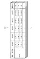
- FIG. 6 is a diagram showing a data configuration example of the actual information 410 according to the present embodiment.
- the actual information 410 is obtained when the control values (rotation direction, designated angle, rotation start time) of each swing camera 52 and the control values are executed in association with the traveling information (speed, traveling direction). Information on the tracked score is stored.
- the speed for example, 10 km / h is assumed to be data belonging to one same range.
- the data of 70 km / h or more and less than 80 km / h is treated as one data in the same range.
- the direction of the road predetermined in the tracking section is set to "1"
- the opposite direction is set to "0".
- the control values of each swing camera 52 are the rotation direction, the designated angle, and the rotation start time.
- the direction of rotation is "1" (for example, from right to left) if the rotation of the target vehicle during tracking is the same as the predetermined direction, and "0" (from left to right) if the direction is opposite.
- the designated angle is, for example, an angle shown as 0 degree (reference value) when parallel to the road, and is an angle designated when starting rotation for tracking the target vehicle.
- the rotation start time is the time (seconds) until the rotation is started after that, based on the time when the designated angle is set.
- the performance information 410 is created by associating the control value of each swing camera 52 with the tracking score for each combination of the speed range (for example, in units of 10 km / h) and the traveling direction.
- the control information creation unit 115 acquires the travel information (speed, traveling direction) information from each reference camera 51 in the tracking section from the image recognition unit 130 in the operation phase.
- the actual information DB 400 is obtained.
- the control value of each swing camera 52 associated with the value of the tracking score which is equal to or more than a predetermined value is acquired.
- the control information is created and output to the device control unit 120. Since the "value of the tracking score that is equal to or higher than the predetermined value" referred to by the control information creation unit 115 is optimally the "value of the highest tracking score", it is referred to as the value of the highest tracking score in the following description. explain.
- control information creating unit 115 excludes the swing camera 52 within one hop from the reference camera 51 when the traveling information (speed, traveling direction) from the reference camera 51 is acquired from the image recognition unit 130.
- control information for setting the preparation angle 45 degrees
- the preparation angle is an angle at which the camera is pointed in the direction in which the moving object (target vehicle) enters, and is, for example, 45 degrees. It is set to prepare in advance in time for tracking the target vehicle.
- the device control unit 120 transmits the control information created by the device cooperation unit 110 to each swing camera 52.
- the control of each swing camera 52 in the operation phase by the moving object tracking device 1 will be described with reference to FIGS. 7 and 8.
- the end point camera (reference camera 51) at the right end of the tracking section detects the approach of the target vehicle (see reference numeral 7a).
- the device control unit 120 of the moving target tracking device 1 acquires the information of the swing camera 52 within one hop from the end point camera with reference to the camera position information 200 (FIG. 5), and enters the operation phase. At the time of entering, the preparation angle is changed (see reference numeral 7b).
- the image recognition unit 130 analyzes the traveling information (speed, traveling direction). Then, the control information creation unit 115 of the moving target tracking device 1 refers to the actual information DB 400, selects the one having the highest tracking score among the corresponding actual information 410, and generates the control information. As a result, the swing camera 52 within one hop from the end point camera at the right end is set to a specified angle, which is the angle at which the target vehicle is actually tracked, and when the rotation start time comes, the camera is rotated to rotate the target vehicle. Capture is performed (see reference numeral 7c). At this time, the control information creation unit 115 changes the swing camera 52 within one hop from the next reference camera 51 in the traveling direction of the vehicle to the preparation angle (see reference numeral 7d).
- the target vehicle is detected by the next reference camera 51, and the traveling information is analyzed by the image recognition unit 130.
- the moving target tracking device 1 recognizes that the speed has been changed in the target vehicle (see reference numeral 8a).
- control information creation unit 115 refers to the actual information DB 400 using the analyzed running information, selects the one having the highest tracking score among the actual information 410 of the corresponding speed, and generates the control information. .. Then, the control information creation unit 115 changes the angle of the swing camera 52 within one hop from the reference camera 51 that detected the target vehicle from the preparation angle to the designated angle (see reference numeral 8b).
- each swing camera 52 rotates the camera when the rotation start time comes, and captures the target vehicle (reference numeral 8c).
- the image recognition unit 130 (tracking score calculation unit 132) of the moving target tracking device 1 calculates the tracking score related to the tracking of the target vehicle (reference numeral). 8d).
- the reference camera 51 and the swing camera 52 are controlled to track the vehicle in cooperation with each other. It becomes possible.
- the image recognition unit 130 acquires image information from each camera device (reference camera 51 and swing camera 52) of the camera device group 50, analyzes the image, and performs each swing camera 52 in the tracking section. Calculate the tracking score for the control information of.
- the image recognition unit 130 includes a tracking target analysis unit 131 and a tracking score calculation unit 132.
- the tracking target analysis unit 131 acquires captured images from the reference camera 51 and the swing camera 52. Then, the tracking target analysis unit 131 analyzes the acquired images of each camera device, acquires the information of the adjacent cameras on the left and right sides of each camera device and the information of the camera position with respect to the road, and in the storage unit 12. It is stored in the camera position information 200. Further, the tracking target analysis unit 131 acquires the traveling information (speed, traveling direction) by analyzing the image acquired from the reference camera 51, and outputs the traveling information (speed, traveling direction) to the device cooperation unit 110.
- the tracking score calculation unit 132 calculates a tracking score (S) for evaluating the control value of the control information of each swing camera 52 based on the following equation (1).
- S T m / T A ⁇ 100 ⁇ formula (1)
- T A is the target vehicle tracking interval is a period of time required for the passage.
- the T A is the end point the camera of the end point of the trace interval from the time of capturing a target vehicle, a value endpoint camera by subtracting the time to start capturing of the target vehicle of the start point of the track section.
- T m is a time during which one or more of the target vehicles that have passed the tracking section recognize the target vehicle at a predetermined recognition rate or higher by any of the swing cameras 52. This tracking score becomes higher as the target vehicle is recognized for a longer period of time throughout the tracking section.
- FIG. 9 is a flowchart showing the flow of the initial setting process executed by the moving target tracking device 1 according to the present embodiment.
- the initial setting unit 111 of the movement target tracking device 1 determines whether or not the current time is the stage of executing the position information creation phase when starting the process (step S1). If the current phase is the stage of executing the position information creation phase, the process proceeds to step S2. If the location information creation phase has already been executed, that is, the learning phase or the operation phase, the process proceeds to step S4.
- step S1 When it is determined in step S1 that the position information creation phase is to be executed (step S1 ⁇ Yes), the initial setting unit 111 creates control information for angle reset for each swing camera 52 (step S2). ).
- the control information for resetting the angle is the control information set to 90 degrees (front angle) with respect to the longitudinal direction of the road in the tracking section.
- the initial setting unit 111 transmits the created control information for angle reset to each swing camera 52 via the device control unit 120 (step S3).
- the process proceeds to the position information creation phase (see FIG. 10) described later.
- step S4 the initial setting unit 111 creates control information for setting the angle of the swing camera 52 within one hop from the reference camera 51 (end point camera) of the end point to the preparation angle (45 degrees with respect to the longitudinal direction of the road). do. Further, the initial setting unit 111 is used for angle resetting for setting the other swing camera 52 (not within one hop from the end point camera) to 90 degrees (front angle) with respect to the longitudinal direction of the road in the tracking section. Create control information. The initial setting unit 111 transmits the created preparation angle control information to the swing camera 52 within one hop from the end point camera via the device control unit 120, and also transmits the generated control information for angle reset to other control information. It is transmitted to the swing camera 52 (step S5).
- the initial setting unit 111 determines whether or not the current phase is the stage for executing the learning phase (step S6). That is, the initial setting unit 111 determines whether the current phase is the stage of executing the learning phase or the operation phase.
- the initial setting unit 111 indicates that the current phase is the stage where the learning phase is completed and the operation phase is executed. For example, the data of the actual information 410 is accumulated and the number of data is the second threshold value. The determination may be made based on the above, or the determination may be made by acquiring information from the external management device (not shown) that the learning phase is completed and the operation phase is executed.
- step S6 ⁇ Yes when the initial setting unit 111 determines that the current phase is the stage for executing the learning phase (step S6 ⁇ Yes), the initial setting unit 111 proceeds to the learning phase (see FIG. 11) described later. On the other hand, when it is determined that the current phase has completed the learning phase and is the stage for executing the operation phase (step S6 ⁇ No), the process proceeds to the operation phase (see FIG. 12) described later.
- FIG. 10 is a flowchart showing a processing flow of the position information creation phase executed by the moving object tracking device 1 according to the present embodiment.
- the image recognition unit 130 tilt target analysis unit 131
- the tracking target analysis unit 131 analyzes the acquired image to create the position information of the adjacency relationship among the camera position information 200 shown in FIG.
- the tracking target analysis unit 131 includes information on "adjacent camera (next to the left)” and “adjacent camera (next to the right)” in the camera position information 200, and the camera position "above” of the swing camera 52 with respect to the road.
- the information of "below” is acquired and stored in the camera position information 200.
- the image recognition unit 130 can grasp the adjacency relationship of the cameras from the order in which each camera device (reference camera 51 and swing camera 52) captures a specific target vehicle and the traveling direction of the target vehicle.
- step S11 the device cooperation unit 110 (position information creation unit 112) of the moving target tracking device 1 acquires the image information of the traveling vehicle in the tracking section from the image recognition unit 130, thereby causing the camera position information 200 (position information creation unit 112).
- position information related to the end point camera (reference camera 51), which is information that has not yet been stored, is created.
- the position information creation unit 112 includes "left end point camera (True / False)", “right end point camera (True / False)", “reference camera (left direction)”, and “left end point camera (True / False)” in the camera position information 200.
- Each information of "reference camera (to the right)” and “camera within one hop” is created and stored in the corresponding part of the camera position information 200. In this way, the moving target tracking device 1 generates the camera position information 200 and ends the position information creation phase.
- FIG. 11 is a flowchart showing a processing flow of a learning phase executed by the moving object tracking device 1 according to the present embodiment.
- the image recognition unit 130 (tracking target analysis unit 131) of the moving target tracking device 1 acquires and analyzes the image from the reference camera 51, and acquires the traveling information (speed, traveling direction) (step S20). Then, the tracking target analysis unit 131 outputs the acquired traveling information (speed, traveling direction) to the device cooperation unit 110.
- the learning data collection unit 113 of the device cooperation unit 110 that has acquired the travel information has the reference camera 51 (end point camera of the start point) at which the acquired travel information (speed, traveling direction) is the start point of the tracking section. It is determined whether or not the information is from (step S21). Then, if the information is not from the end point camera of the start point (step S21 ⁇ No), the learning data collection unit 113 proceeds to step S24. On the other hand, if the information is from the end point camera of the start point (step S21 ⁇ Yes), the process proceeds to the next step S22.
- step S22 the learning data collection unit 113 creates control information for setting the preparation angle (45 degrees) for the other swing cameras 52 except the swing camera 52 located within one hop from the end point camera of the start point. Then, the learning data collection unit 113 transmits the created preparation angle control information to the other swing cameras 52 except the swing camera 52 located within one hop from the end point camera of the start point via the device control unit 120. (Step S23). As a result, in the other swing camera 52, the direction of the camera is set to the preparation angle.
- step S24 determines whether or not the number of data of the actual information 410 stored in the actual information DB 400 exceeds a predetermined threshold value. Then, if the number of data does not exceed a predetermined threshold value (step S24 ⁇ No), the process proceeds to step S25.
- step S25 the learning data collecting unit 113 randomly randomizes the information of the control values (rotation direction, designated angle, rotation start time) of each swing camera 52 corresponding to the traveling information (speed, traveling direction) acquired in step S20.
- the control information of each swing camera 52 is created by setting the value of.
- the learning data collecting unit 113 stores the information of the control value of each swing camera 52 corresponding to the traveling information (speed, traveling direction) in the learning data 300.
- the learning data collection unit 113 transmits the created control information of each swing camera 52 to each swing camera 52 via the device control unit 120 (step S26).
- each swing camera 52 executes control based on randomly set control values. Then, the process proceeds to the next step S29.
- step S24 if the number of data of the actual information 410 exceeds a predetermined threshold value (step S24 ⁇ Yes), the process proceeds to step S27.
- step S27 the learning data collecting unit 113 outputs the traveling information (speed, traveling direction) acquired in step S20 to the machine learning unit 114. Then, the machine learning unit 114 inputs the traveling information (speed, traveling direction) to the learning device 100, and as output data, the control values (rotation direction, designated angle, rotation start time) of each swing camera 52 are used. Calculate the information.
- step S28 the learning data collection unit 113 acquires the information of the control value obtained by the machine learning from the machine learning unit 114, and creates the control information of each swing camera 52. Then, the learning data collecting unit 113 stores the information of the control value of each swing camera 52 corresponding to the traveling information (speed, traveling direction) in the learning data 300. Then, the learning data collection unit 113 transmits the created control information of each swing camera 52 to each swing camera 52 via the device control unit 120. As a result, each swing camera 52 executes control based on the control value calculated by the learner 100. Then, the process proceeds to the next step S29.
- step S29 when the tracking target analysis unit 131 of the image recognition unit 130 acquires an image of the target vehicle, the image is an image from the reference camera 51 (end point camera at the end point) of the end point which is the end point of the tracking section. Judge whether or not. Then, if it is not the image from the end point camera at the end point (step S29 ⁇ No), the process returns to step S20 and the process is continued. On the other hand, if it is an image from the end point camera at the end point (step S29 ⁇ Yes), the process proceeds to the next step S30.
- step S30 the tracking score calculation unit 132 of the image recognition unit 130 calculates the tracking score using the above formula (1). Then, the tracking score calculation unit 132 outputs the calculated tracking score to the device cooperation unit 110.
- the learning data collecting unit 113 of the device cooperation unit 110 generates the learning data 300 by storing the acquired tracking score in association with the travel information and the control value stored in advance (step S31).
- the machine learning unit 114 inputs the running information, the control value, and the tracking score shown in the learning data 300 generated in step S31 into the learning device 100 to learn (step S32). Then, the machine learning unit 114 stores the running information, the control value, and the tracking score information learned by the learning device 100 in the actual information 410 (FIG. 6), which is a collection of data for each speed within a predetermined range. As a result (step S33), the actual information 410 is updated and the process is completed.
- the moving target tracking device 1 sets a random value as a control value (rotation direction, designated angle, rotation start time).
- the tracking score is calculated from the result of control using the control value obtained by the learner 100. Then, as a result of this learning phase, the moving target tracking device 1 can create performance information 410 that summarizes the tracking scores corresponding to the control values for each speed within a predetermined range.
- a target score is defined when a control value is generated. ..
- the machine learning unit 114 designates this target score as, for example, a maximum of 100 points, and causes the learning device 100 to calculate the control value of each swing camera 52.
- the image recognition unit 130 tilts the tracking score, which is the result of controlling each swing camera 52 by the calculated control value (for example, 40 points), and the running information and the control value at that time.
- the tracking score (40 points) is also trained by the learning device 100 as learning data, and the learning device 100 is updated.
- the device cooperation unit 110 calculates the control value according to the current state (Plan). Then, the device control unit 120 controls each swing camera 52 with the control value according to the Plan (Do). The controlled result is calculated by the image recognition unit 130 (tracking score calculation unit 132) as a tracking score (Check), and is trained by the learner 100 as new learning data (Action). In the learning phase, the learning device 100 can generate an optimum control value by repeating such a PDCA cycle.
- FIG. 12 is a flowchart showing a processing flow of an operation phase executed by the moving object tracking device 1 according to the present embodiment.
- the image recognition unit 130 tilt object analysis unit 131 of the moving object tracking device 1 acquires and analyzes the image from the reference camera 51, and acquires the traveling information (speed, traveling direction) (step S40). Then, the tracking target analysis unit 131 outputs the acquired traveling information (speed, traveling direction) to the device cooperation unit 110.
- the control information creation unit 115 of the device cooperation unit 110 that has acquired the travel information has the reference camera 51 (end point camera of the start point) at which the acquired travel information (speed, traveling direction) is the start point of the tracking section. It is determined whether or not the information is from (step S41). Then, when the control information creation unit 115 is not information from the end point camera of the start point (step S41 ⁇ No), the control information creation unit 115 proceeds to step S44. On the other hand, if the information is from the end point camera of the start point (step S41 ⁇ Yes), the process proceeds to the next step S42.
- step S42 the control information creation unit 115 creates control information for setting the preparation angle (45 degrees) for the other swing cameras 52 except the swing camera 52 located within one hop from the end point camera of the start point. Then, the control information creation unit 115 transmits the created preparation angle control information to the other swing cameras 52 except the swing camera 52 located within one hop from the end point camera of the start point via the device control unit 120. (Step S43). As a result, in the other swing camera 52, the direction of the camera is set to the preparation angle.
- the control information creation unit 115 refers to the actual information 410 (FIG. 6) of the corresponding speed and direction by using the traveling information (speed, traveling direction) acquired in step S40, and the actual result.
- the information of the control value of each swing camera 52 in the tracking score having the highest score is acquired.
- the control information creation unit 115 creates control information for each swing camera 52 using the acquired control values (rotation direction, designated angle, rotation start time) of each swing camera 52.
- the control information creation unit 115 transmits the created control information to each swing camera 52 via the device control unit 120 (step S45).
- the angle is set to the designated angle, and control by the control value having the highest tracking score in the entire tracking section is executed as a past achievement.
- step S46 when the tracking target analysis unit 131 of the image recognition unit 130 acquires an image of the target vehicle, is the image from the reference camera 51 (end point camera at the end point) at the end point of the tracking section? It is determined whether or not (step S46). Then, if it is not the image from the end point camera at the end point (step S46 ⁇ No), the process returns to step S40 and the process is continued. On the other hand, if it is an image from the end point camera at the end point (step S46 ⁇ Yes), the process ends.
- the moving target tracking device 1 refers to the actual information 410 based on the traveling information (speed, traveling direction) obtained from the image acquired from the reference camera 51, and uses the control value having the highest tracking score.
- the control information of each swing camera 52 is created. Therefore, each swing camera 52 can be controlled with the optimum control value for the entire tracking section. Further, since the control information is created based on the speed obtained for each reference camera 51, it is possible to control the swing camera 52 to follow even if the speed of the target vehicle is changed such as acceleration or deceleration. It will be possible.
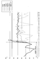
- FIG. 13 is a diagram showing an evaluation result of a control value calculated by the learning device 100.
- method 1 is "random”.
- Method 2 is a "random forest”.
- Method 3 is the "multilayer perceptron (neural network)" adopted in this embodiment.
- the horizontal axis of FIG. 13 is the number of trials, and the vertical axis is the score.
- the number of trials number of vehicle trips required to find a control value having a target score of "65" or higher is evaluated.
- the "multilayer perceptron" of method 3 is implemented by python scikit-learn (python is a registered trademark), and the parameters are changed.
- method 3-1 initial parameter setting
- the hidden layer is set to "3 layers (100,100,100)”
- the number of learning iterations max_tier is set to "200”
- alpha penalty of L2 normalization
- method 3-2 the number of learning iterations max_tier "5000" is changed from method 3-1 (initial parameter setting).
- the hidden layer is changed to "6 layers (100,100,100,100,100,100,100)" from method 3-1 (initial parameter setting).
- the method 3 "multilayer perceptron” is an effective method for searching for a control value with a high score earlier than the method 1 "random” and the method 2 "random forest".
- method 3-1 and method 3-3 the learning of the initial data set is completed, and the search of the target score or more is successful in the second time from the start of estimation. It is presumed that Method 3-2 was overfitted because the number of learning iterations was set large. Therefore, it was shown that the method of Method 3 "Multilayer Perceptron” is effective by setting hyperparameters such as preventing overfitting and increasing the number of hidden layers.
- the moving object tracking device 1 is realized by, for example, a computer 900 having a configuration as shown in FIG.
- FIG. 14 is a hardware configuration diagram showing an example of a computer 900 that realizes the function of the moving object tracking device 1 according to the present embodiment.
- the computer 900 has a CPU 901, a ROM (Read Only Memory) 902, a RAM 903, an HDD (Hard Disk Drive) 904, an input / output I / F (Interface) 905, a communication I / F 906, and a media I / F 907.
- the CPU 901 operates based on the program stored in the ROM 902 or the HDD 904, and is controlled by the control unit 10 of the moving target tracking device 1 shown in FIG.
- the ROM 902 stores a boot program executed by the CPU 901 when the computer 900 is started, a program related to the hardware of the computer 900, and the like.
- the CPU 901 controls an input device 910 such as a mouse and a keyboard and an output device 911 such as a display and a printer via the input / output I / F 905.
- the CPU 901 acquires data from the input device 910 and outputs the generated data to the output device 911 via the input / output I / F 905.
- a GPU Graphics Processing Unit
- a GPU may be used together with the CPU 901 as the processor.
- the HDD 904 stores a program executed by the CPU 901, data used by the program, and the like.
- the communication I / F906 receives data from another device via a communication network (for example, NW (Network) 920) and outputs the data to the CPU 901, and the data generated by the CPU 901 is transmitted to another device via the communication network. Send to the device.
- NW Network
- the media I / F907 reads the program or data stored in the recording medium 912 and outputs the program or data to the CPU 901 via the RAM 903.
- the CPU 901 loads the program related to the target processing from the recording medium 912 onto the RAM 903 via the media I / F 907, and executes the loaded program.
- the recording medium 912 includes an optical recording medium such as a DVD (Digital Versatile Disc) and a PD (Phase change rewritable Disk), a magneto-optical recording medium such as an MO (Magneto Optical disk), a magnetic recording medium, a conductor memory tape medium, a semiconductor memory, and the like. Is.
- the CPU 901 of the computer 900 realizes the function of the moving target tracking device 1 by executing the program loaded on the RAM 903. Further, the data in the RAM 903 is stored in the HDD 904. The CPU 901 reads a program related to the target process from the recording medium 912 and executes it. In addition, the CPU 901 may read a program related to the target processing from another device via the communication network (NW920).
- NW920 communication network
- the moving object tracking device is the moving object tracking device 1 that tracks the moving object by controlling the camera device group 50, and the camera device group 50 is a reference for fixing the camera and photographing the moving object. It is composed of a camera 51 and a swing camera 52 that makes the camera follow the movement of the moving object to take a picture.
- the position information creation unit 112 that creates camera position information indicating the adjacency relationship between the plurality of reference cameras 51 and the plurality of swinging cameras 52, and the image from the reference camera 51 are acquired, and the speed of the moving target is obtained.
- the tracking target analysis unit 131 that detects the traveling information indicating the traveling direction, and the ratio that any one of the plurality of swing cameras 52 could capture the moving target in the entire tracking section when the moving target passes through the tracking section.
- the tracking score calculation unit 132 that calculates the tracking score, which is the evaluation value indicated by, and the running information are input, the rotation direction of the swing camera 52, the designated angle at the start of tracking, and the designated angle of each of the swing cameras 52 are input.
- It has a learning device (learner 100) that outputs a control value including a rotation start time from the time when it is set to, and a tracking score as a control result of each swing camera 52 by the control value obtained from the learning device.
- the control information creation unit 115 that acquires the control value of each swing camera 52 corresponding to the tracking score that is equal to or higher than a predetermined value, creates control information, and transmits the control information to each swing camera 52. , Is provided.
- the moving target tracking device 1 creates camera position information indicating the adjacency relationship between the reference camera 51 and the swing camera 52, and then uses the traveling information (speed, traveling direction) obtained from the reference camera 51. , Information on the control values (rotation direction, designated angle, rotation start time) of each swing camera 52 can be acquired with reference to the actual information 410, and control information can be created. Since the moving target tracking device 1 creates this control information according to the information from each reference camera 51, even if the speed of the moving target is changed, each swing camera 52 can follow it. ..
- the moving target tracking device 1 acquires the control value corresponding to the tracking score (more preferably, the highest tracking score) which is equal to or higher than the predetermined value by referring to the actual information 410, it is optimal for the entire tracking section.
- Each swing camera 52 can be controlled so as to be.
- the control information creation unit 115 is positioned next in the traveling direction of the movement target in the tracking section.
- the reference camera to be used is specified by using the camera position information 200, and the preparation angle is set to the angle at which the camera is pointed toward the direction in which the moving object enters with respect to the swinging camera 52 that follows from the specified reference camera 51 in the traveling direction. It is characterized in that control information to be set is created and transmitted.
- the moving target tracking device 1 is moved to the side in the direction in which the moving target invades in advance. Since the swing camera 52 is oriented and prepared, it is possible to reliably follow the moving target.
- the learning device (learner 100) is a learning device that calculates a control value of a camera device group that tracks a moving object
- the camera device group 50 is a reference for fixing the camera and photographing the moving object. It is composed of a camera 51 and a swing camera 52 that takes a picture by following the movement of the moving object, and shows the speed and the traveling direction of the moving object obtained by analyzing the image acquired from the reference camera 51. Travel information, control values including the rotation direction of the swing camera 52, the specified angle at the start of tracking, the rotation start time from the time when the specified angle is set to the rotation, and the movement target of each of the swing cameras 52.
- the learning device (learner 100) inputs the traveling information (speed, traveling direction) from the reference camera 51, the learning device (learning device 100) has a higher tracking score, and the control value (rotation direction) of each swing camera 52. , Specified angle, rotation start time) information can be generated.
- the present invention is not limited to the embodiments described above, and many modifications can be made by a person having ordinary knowledge in the art within the technical idea of the present invention.
- the rotation direction, the designated angle, and the rotation start time have been described as examples of the control values of the swing camera 52.
- the present invention is not limited to this example, and for example, information on the rotation speed of the swing camera 52 may be included.
- the tracking accuracy can be improved by controlling the swing camera 52 by adding the information of the rotation speed.
- learning is performed using random values at the initial stage of the learning phase, but for example, learning data used in other tracking sections may be transferred and learned.
- the learning device 100 (learning device) can be trained so that the control value that reaches the target evaluation value (tracking score) can be found earlier. Further, the tracking score may be calculated and the learning data may be generated even in the operation phase. By training the generated learning data in the learning device 100 (learning device), it is possible to acquire the performance information 410 having a higher tracking score and improve the tracking accuracy of the target vehicle.
- Moving target tracking device 10
- Control unit 11
- Input / output unit 12 Storage unit (storage means) 50
- Camera device group 51
- Reference camera 52 Swing camera
- Learner (learning device) 110
- Device cooperation unit 111
- Initial setting unit 112
- Position information creation unit 113
- Learning data collection unit 114
- Machine learning unit 115
- Control information creation unit 120
- Device control unit 130 Image recognition unit 131 Tracking target analysis unit 132 Tracking score calculation unit 200
- Camera position information 300 Learning data 400
- Achievement information DB Achievement information 1000 Movement target tracking system
Landscapes
- Engineering & Computer Science (AREA)
- Multimedia (AREA)
- Signal Processing (AREA)
- Physics & Mathematics (AREA)
- General Physics & Mathematics (AREA)
- Computer Vision & Pattern Recognition (AREA)
- Theoretical Computer Science (AREA)
- Software Systems (AREA)
- Traffic Control Systems (AREA)
- Image Analysis (AREA)
Priority Applications (3)
| Application Number | Priority Date | Filing Date | Title |
|---|---|---|---|
| PCT/JP2020/007345 WO2021171338A1 (ja) | 2020-02-25 | 2020-02-25 | 移動対象追跡装置、移動対象追跡方法、移動対象追跡システム、および、学習装置、並びに、プログラム |
| JP2022502346A JP7255745B2 (ja) | 2020-02-25 | 2020-02-25 | 移動対象追跡装置、移動対象追跡方法、移動対象追跡システム、および、学習装置、並びに、プログラム |
| US17/801,889 US11983891B2 (en) | 2020-02-25 | 2020-02-25 | Moving target tracking device, moving target tracking method, moving target tracking system, learning device, and program |
Applications Claiming Priority (1)
| Application Number | Priority Date | Filing Date | Title |
|---|---|---|---|
| PCT/JP2020/007345 WO2021171338A1 (ja) | 2020-02-25 | 2020-02-25 | 移動対象追跡装置、移動対象追跡方法、移動対象追跡システム、および、学習装置、並びに、プログラム |
Publications (1)
| Publication Number | Publication Date |
|---|---|
| WO2021171338A1 true WO2021171338A1 (ja) | 2021-09-02 |
Family
ID=77491267
Family Applications (1)
| Application Number | Title | Priority Date | Filing Date |
|---|---|---|---|
| PCT/JP2020/007345 Ceased WO2021171338A1 (ja) | 2020-02-25 | 2020-02-25 | 移動対象追跡装置、移動対象追跡方法、移動対象追跡システム、および、学習装置、並びに、プログラム |
Country Status (3)
| Country | Link |
|---|---|
| US (1) | US11983891B2 (https=) |
| JP (1) | JP7255745B2 (https=) |
| WO (1) | WO2021171338A1 (https=) |
Cited By (1)
| Publication number | Priority date | Publication date | Assignee | Title |
|---|---|---|---|---|
| JP2025515717A (ja) * | 2022-05-09 | 2025-05-20 | コグネックス・コーポレイション | マシンビジョンシステムをコミッショニングするためのシステム及び方法 |
Families Citing this family (3)
| Publication number | Priority date | Publication date | Assignee | Title |
|---|---|---|---|---|
| US12380701B2 (en) * | 2023-05-18 | 2025-08-05 | SanDisk Technologies, Inc. | Predictive adjustment of multi-camera surveillance video data capture |
| US12401765B2 (en) | 2023-06-27 | 2025-08-26 | SanDisk Technologies, Inc. | Predictive adjustment of multi-camera surveillance video data capture using graph maps |
| US12462567B2 (en) | 2024-03-18 | 2025-11-04 | SanDisk Technologies, Inc. | Predictive adjustment of distributed surveillance video data capture using networks of graph maps |
Citations (3)
| Publication number | Priority date | Publication date | Assignee | Title |
|---|---|---|---|---|
| JPH04211900A (ja) * | 1990-04-27 | 1992-08-03 | Hitachi Ltd | 交通流計測装置及び交通流計測制御装置 |
| WO2017047687A1 (ja) * | 2015-09-17 | 2017-03-23 | 株式会社日立国際電気 | 監視システム |
| JP2019124966A (ja) * | 2019-04-22 | 2019-07-25 | 株式会社ニコン | レンズ鏡筒およびカメラシステム |
Family Cites Families (13)
| Publication number | Priority date | Publication date | Assignee | Title |
|---|---|---|---|---|
| US8036425B2 (en) * | 2008-06-26 | 2011-10-11 | Billy Hou | Neural network-controlled automatic tracking and recognizing system and method |
| CN105191505B (zh) * | 2013-03-18 | 2019-01-15 | 飞利浦灯具控股公司 | 用于室外照明网络的信息管理和控制的方法和装置 |
| US10839203B1 (en) * | 2016-12-27 | 2020-11-17 | Amazon Technologies, Inc. | Recognizing and tracking poses using digital imagery captured from multiple fields of view |
| US10699421B1 (en) * | 2017-03-29 | 2020-06-30 | Amazon Technologies, Inc. | Tracking objects in three-dimensional space using calibrated visual cameras and depth cameras |
| US10445871B2 (en) * | 2017-05-22 | 2019-10-15 | General Electric Company | Image analysis neural network systems |
| US11379996B2 (en) * | 2017-11-14 | 2022-07-05 | Apple Inc. | Deformable object tracking |
| US11042994B2 (en) * | 2017-11-15 | 2021-06-22 | Toyota Research Institute, Inc. | Systems and methods for gaze tracking from arbitrary viewpoints |
| WO2019100011A1 (en) * | 2017-11-17 | 2019-05-23 | Divine Logic, Inc. | Systems and methods for tracking items |
| US11157745B2 (en) * | 2018-02-20 | 2021-10-26 | Scenera, Inc. | Automated proximity discovery of networked cameras |
| US11842572B2 (en) * | 2018-06-21 | 2023-12-12 | Baseline Vision Ltd. | Device, system, and method of computer vision, object tracking, image analysis, and trajectory estimation |
| US12012127B2 (en) * | 2019-10-26 | 2024-06-18 | Zoox, Inc. | Top-down view object detection and tracking |
| WO2021095916A1 (ko) * | 2019-11-13 | 2021-05-20 | 주식회사 벡터시스 | 객체의 이동경로를 추적할 수 있는 추적시스템 |
| US11475249B2 (en) * | 2020-04-30 | 2022-10-18 | Electronic Arts Inc. | Extending knowledge data in machine vision |
-
2020
- 2020-02-25 US US17/801,889 patent/US11983891B2/en active Active
- 2020-02-25 WO PCT/JP2020/007345 patent/WO2021171338A1/ja not_active Ceased
- 2020-02-25 JP JP2022502346A patent/JP7255745B2/ja active Active
Patent Citations (3)
| Publication number | Priority date | Publication date | Assignee | Title |
|---|---|---|---|---|
| JPH04211900A (ja) * | 1990-04-27 | 1992-08-03 | Hitachi Ltd | 交通流計測装置及び交通流計測制御装置 |
| WO2017047687A1 (ja) * | 2015-09-17 | 2017-03-23 | 株式会社日立国際電気 | 監視システム |
| JP2019124966A (ja) * | 2019-04-22 | 2019-07-25 | 株式会社ニコン | レンズ鏡筒およびカメラシステム |
Cited By (1)
| Publication number | Priority date | Publication date | Assignee | Title |
|---|---|---|---|---|
| JP2025515717A (ja) * | 2022-05-09 | 2025-05-20 | コグネックス・コーポレイション | マシンビジョンシステムをコミッショニングするためのシステム及び方法 |
Also Published As
| Publication number | Publication date |
|---|---|
| US11983891B2 (en) | 2024-05-14 |
| JPWO2021171338A1 (https=) | 2021-09-02 |
| JP7255745B2 (ja) | 2023-04-11 |
| US20230082600A1 (en) | 2023-03-16 |
Similar Documents
| Publication | Publication Date | Title |
|---|---|---|
| WO2021171338A1 (ja) | 移動対象追跡装置、移動対象追跡方法、移動対象追跡システム、および、学習装置、並びに、プログラム | |
| CN110371112A (zh) | 一种自动驾驶车辆的智能避障系统及方法 | |
| CN111709974A (zh) | 基于rgb-d图像的人体跟踪方法及装置 | |
| CN114694095B (zh) | 确定车辆进出泊位的方法、装置、设备和存储介质 | |
| CN114898326A (zh) | 基于深度学习的单行道车辆逆行检测方法、系统及设备 | |
| CN109686031B (zh) | 基于安防的识别跟随方法 | |
| KR102493930B1 (ko) | 강화학습 기반 신호 제어 장치 및 신호 제어 방법 | |
| CA3196344A1 (en) | Rail feature identification system | |
| CN109740462B (zh) | 目标的识别跟随方法 | |
| KR102452460B1 (ko) | Ptz 카메라를 통해 cctv 공간모델을 생성하는 장치, 방법 및 프로그램 | |
| JP2001216519A (ja) | 交通監視装置 | |
| KR102371995B1 (ko) | 다수의 회전형 카메라를 이용한 차로별 통행 정보 제공 시스템 및 방법 | |
| CN117115752A (zh) | 一种高速公路视频监控方法及系统 | |
| KR20210125371A (ko) | 교통 상황 분석 방법 및 장치 | |
| CN114581847A (zh) | 一种基于gam跟踪器的社区行人异常行为检测方法和装置 | |
| CN117830971A (zh) | 一种基于隧道巡逻机器人的高速隧道交通状态监测方法 | |
| CN109977796A (zh) | 尾随通行检测方法及装置 | |
| CN112560546B (zh) | 抛洒行为检测方法、装置及存储介质 | |
| CN115909223A (zh) | 一种wim系统信息与监控视频数据匹配的方法和系统 | |
| CN114979558A (zh) | 一种基于人脸识别进行风险人物跟踪的跟踪系统和跟踪方法 | |
| Wang et al. | Automatic detection and tracking of precast walls from surveillance construction site videos | |
| CN114549585B (zh) | 视频追踪方法、装置、设备、机器可读存储介质及系统 | |
| WO2024185226A1 (ja) | 状態判定装置及び状態判定方法 | |
| CN110942642B (zh) | 一种基于视频的交通缓驶检测方法及系统 | |
| JP2023131956A (ja) | 状態判定装置、状態判定方法および移動体支援システム |
Legal Events
| Date | Code | Title | Description |
|---|---|---|---|
| 121 | Ep: the epo has been informed by wipo that ep was designated in this application |
Ref document number: 20920791 Country of ref document: EP Kind code of ref document: A1 |
|
| ENP | Entry into the national phase |
Ref document number: 2022502346 Country of ref document: JP Kind code of ref document: A |
|
| NENP | Non-entry into the national phase |
Ref country code: DE |
|
| 122 | Ep: pct application non-entry in european phase |
Ref document number: 20920791 Country of ref document: EP Kind code of ref document: A1 |