WO2021166894A1 - 重量推定装置及びプログラム - Google Patents
重量推定装置及びプログラム Download PDFInfo
- Publication number
- WO2021166894A1 WO2021166894A1 PCT/JP2021/005666 JP2021005666W WO2021166894A1 WO 2021166894 A1 WO2021166894 A1 WO 2021166894A1 JP 2021005666 W JP2021005666 W JP 2021005666W WO 2021166894 A1 WO2021166894 A1 WO 2021166894A1
- Authority
- WO
- WIPO (PCT)
- Prior art keywords
- image
- animal
- weight
- shape
- information
- Prior art date
Links
- 241001465754 Metazoa Species 0.000 claims abstract description 346
- 238000000034 method Methods 0.000 claims description 113
- 238000012545 processing Methods 0.000 claims description 20
- 210000003205 muscle Anatomy 0.000 claims description 16
- 238000003384 imaging method Methods 0.000 abstract description 7
- 238000010586 diagram Methods 0.000 description 16
- 230000037396 body weight Effects 0.000 description 9
- 230000006870 function Effects 0.000 description 9
- 239000004973 liquid crystal related substance Substances 0.000 description 5
- 238000012937 correction Methods 0.000 description 4
- 230000000694 effects Effects 0.000 description 4
- 210000001835 viscera Anatomy 0.000 description 4
- 230000000007 visual effect Effects 0.000 description 4
- 238000002474 experimental method Methods 0.000 description 3
- 241000282887 Suidae Species 0.000 description 2
- 238000002591 computed tomography Methods 0.000 description 2
- 230000002950 deficient Effects 0.000 description 2
- 238000001514 detection method Methods 0.000 description 2
- 238000000513 principal component analysis Methods 0.000 description 2
- 241001481833 Coryphaena hippurus Species 0.000 description 1
- 240000006829 Ficus sundaica Species 0.000 description 1
- 125000002066 L-histidyl group Chemical group [H]N1C([H])=NC(C([H])([H])[C@](C(=O)[*])([H])N([H])[H])=C1[H] 0.000 description 1
- 230000037237 body shape Effects 0.000 description 1
- 244000144972 livestock Species 0.000 description 1
- 238000005259 measurement Methods 0.000 description 1
Images


Classifications
-
- G—PHYSICS
- G06—COMPUTING; CALCULATING OR COUNTING
- G06T—IMAGE DATA PROCESSING OR GENERATION, IN GENERAL
- G06T7/00—Image analysis
- G06T7/50—Depth or shape recovery
- G06T7/521—Depth or shape recovery from laser ranging, e.g. using interferometry; from the projection of structured light
-
- G—PHYSICS
- G01—MEASURING; TESTING
- G01F—MEASURING VOLUME, VOLUME FLOW, MASS FLOW OR LIQUID LEVEL; METERING BY VOLUME
- G01F17/00—Methods or apparatus for determining the capacity of containers or cavities, or the volume of solid bodies
-
- G—PHYSICS
- G01—MEASURING; TESTING
- G01B—MEASURING LENGTH, THICKNESS OR SIMILAR LINEAR DIMENSIONS; MEASURING ANGLES; MEASURING AREAS; MEASURING IRREGULARITIES OF SURFACES OR CONTOURS
- G01B11/00—Measuring arrangements characterised by the use of optical techniques
- G01B11/22—Measuring arrangements characterised by the use of optical techniques for measuring depth
-
- G—PHYSICS
- G01—MEASURING; TESTING
- G01S—RADIO DIRECTION-FINDING; RADIO NAVIGATION; DETERMINING DISTANCE OR VELOCITY BY USE OF RADIO WAVES; LOCATING OR PRESENCE-DETECTING BY USE OF THE REFLECTION OR RERADIATION OF RADIO WAVES; ANALOGOUS ARRANGEMENTS USING OTHER WAVES
- G01S17/00—Systems using the reflection or reradiation of electromagnetic waves other than radio waves, e.g. lidar systems
- G01S17/88—Lidar systems specially adapted for specific applications
- G01S17/89—Lidar systems specially adapted for specific applications for mapping or imaging
-
- H—ELECTRICITY
- H04—ELECTRIC COMMUNICATION TECHNIQUE
- H04N—PICTORIAL COMMUNICATION, e.g. TELEVISION
- H04N7/00—Television systems
- H04N7/18—Closed-circuit television [CCTV] systems, i.e. systems in which the video signal is not broadcast
- H04N7/183—Closed-circuit television [CCTV] systems, i.e. systems in which the video signal is not broadcast for receiving images from a single remote source
-
- G—PHYSICS
- G01—MEASURING; TESTING
- G01B—MEASURING LENGTH, THICKNESS OR SIMILAR LINEAR DIMENSIONS; MEASURING ANGLES; MEASURING AREAS; MEASURING IRREGULARITIES OF SURFACES OR CONTOURS
- G01B11/00—Measuring arrangements characterised by the use of optical techniques
- G01B11/24—Measuring arrangements characterised by the use of optical techniques for measuring contours or curvatures
-
- G—PHYSICS
- G01—MEASURING; TESTING
- G01G—WEIGHING
- G01G17/00—Apparatus for or methods of weighing material of special form or property
- G01G17/08—Apparatus for or methods of weighing material of special form or property for weighing livestock
-
- G—PHYSICS
- G06—COMPUTING; CALCULATING OR COUNTING
- G06T—IMAGE DATA PROCESSING OR GENERATION, IN GENERAL
- G06T2207/00—Indexing scheme for image analysis or image enhancement
- G06T2207/10—Image acquisition modality
- G06T2207/10028—Range image; Depth image; 3D point clouds
Definitions
- the present invention relates to a weight estimation device and a program.
- Patent Document 1 describes a configuration in which an animal is photographed from a predetermined imaging direction and the weight of the animal is measured (estimated) from the photographed image. According to the above configuration, it is not necessary to keep the animal stationary on the scale, so that the above-mentioned problem is suppressed.
- the weight estimation device of the present invention is based on an image acquisition unit that acquires an image of an animal, a shape identification unit that specifies the shape of a predetermined part of the animal from the image, and a shape of the predetermined part.
- the information generation unit includes an information generation unit that generates estimation information used for estimating the weight of the animal, and a weight estimation unit that estimates the weight based on the estimation information.
- the information generation unit is an animal from the first direction. It is possible to generate estimation information when the first image of the animal is acquired, and the estimation information is also generated when the second image of the animal is acquired from the second direction different from the first direction. It can be generated.
- the weight of the animal when the first image of the animal taken from the first direction is acquired, the weight of the animal can be estimated, and the animal is taken from the second direction different from the first direction. 2
- the weight of the animal can be estimated even when the image is acquired. Therefore, as compared with the configuration of Patent Document 1, the degree of freedom in the photographing direction at which the weight related to the animal can be estimated is improved.
- the degree of freedom in the photographing direction at which the weight related to the animal can be estimated is improved.
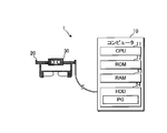
- FIG. 1 is a hardware configuration diagram of the weight estimation device 1. As shown in FIG. 1, the weight estimation device 1 includes a computer 10, a head-mounted display 20, and a depth camera 30. Each of the above configurations is communicably connected.
- the computer 10 includes a CPU (Central Processing Unit) 11, a ROM (Read Only Memory) 12, a RAM (Random access memory) 13, and an HDD (Hard Disk Drive) 14.
- a portable computer for example, a notebook computer
- a desktop personal computer may be adopted as the computer 10.
- the HDD 14 of the computer 10 stores various data including the weight estimation program PG.
- the CPU 11 realizes various functions (weight estimation unit 108, etc.) described later.
- the RAM 13 temporarily stores various types of information that the CPU 11 refers to when executing a program, for example.
- the ROM 12 non-volatilely stores various types of information.
- the weight measurement program PG may be stored in a device other than the HDD 14.
- the head-mounted display 20 can be fixed to the user's head, and a well-known head-mounted display can be appropriately adopted.
- a well-known head-mounted display can be appropriately adopted.
- the head-mounted display 20 one including a small liquid crystal screen and a half mirror can be adopted.
- the above-mentioned small liquid crystal screen can display various images, and the image displayed on the small liquid crystal screen is reflected by the half mirror and visually recognized by the user. With the above configuration, when the user looks at the scenery through the half mirror, the image displayed on the small liquid crystal screen is visually recognized by being superimposed on the scenery.
- the head-mounted display 20 is not limited to the above examples.
- the depth camera 30 generates a distance image (three-dimensional image) including depth information indicating the distance to the subject. For example, as the distance image, a point cloud image taken by LIDAR (Light Detection and Ringing, Laser Imaging Detection and Ringing) technology is assumed. Further, the depth camera 30 is provided with a tilt sensor. The above tilt sensor detects the magnitude of tilt in the photographing direction with respect to the vertical direction.
- LIDAR Light Detection and Ringing, Laser Imaging Detection and Ringing
- the depth camera 30 is fixed to the head-mounted display 20. Therefore, when the user attaches the head-mounted display 20 to the head, the depth camera 30 is fixed at a specific position when viewed from the user. Specifically, the depth camera 30 is fixed at a position where the shooting direction substantially coincides with the line-of-sight direction of the user.
- the scenery visually recognized by the user is photographed by the depth camera 30. Therefore, the user can photograph the animal by moving the line-of-sight direction (face direction) so that the animal is located in his / her field of view.
- the depth camera 30 may be held by the user and an image of an animal may be captured.
- the configuration of the present embodiment has an advantage that the user can freely use both hands.
- the image taken by the depth camera 30 is displayed on the head-mounted display 20 (small liquid crystal screen). Specifically, the image taken by the depth camera 30 is displayed on the head-mounted display 20 in real time. With the above configuration, the user can confirm the image taken by the depth camera 30 in real time. However, a configuration may be adopted in which the image taken by the depth camera 30 is not displayed in real time.
- the image of the animal taken by the depth camera 30 is input to the computer 10.
- the computer 10 estimates the weight of the animal (eg, the weight of the carcass) from the input image by executing the weight estimation program PG.
- the above functions will be described in detail below.
- FIG. 2 is a functional block diagram of the weight estimation device 100.
- the weight estimation device 100 includes an image capturing unit 101, a display unit 102, an image acquisition unit 103, a shape specifying unit 104, a half body selection unit 105, an information generation unit 106, a carcass model storage unit 107, and a weight estimation unit 108.
- NS When the CPU 11 executes the weight estimation program PG, each of the above functions is realized.
- the image capturing unit 101 can capture an image of an animal. Specifically, the image capturing unit 101 is fixed at a specific position when viewed from the user, and can photograph an animal located in the line-of-sight direction of the user. For example, the depth camera 30 functions as an image capturing unit 101.
- the display unit 102 can display various images including the image captured by the image capturing unit 101 (see FIG. 7A described later). For example, the head-mounted display 20 functions as a display unit 102.
- the image acquisition unit 103 acquires an image of an animal (see FIG. 3B described later). Specifically, the image captured by the image capturing unit 101 includes an image such as a background in addition to an animal image. The image acquisition unit 103 acquires an image representing one animal extracted from the image captured by the image acquisition unit 101. The image of the animal acquired by the image acquisition unit 103 is used to estimate the weight of the animal.
- the image acquisition unit 103 of the present embodiment acquires an animal image from the image captured by the image capturing unit 101 by the area expansion method. Specifically, the image acquisition unit 103 specifies one pixel as a seed pixel in the image captured by the image capturing unit 101. Of the images (objects) included in the images captured by the image capturing unit 101, the image acquisition unit 103 acquires an image in which each pixel constituting itself includes a seed pixel. In the above configuration, by specifying any of the pixels constituting the image of the animal as seed pixels, the image of the animal is extracted and acquired from the image taken by the image capturing unit 101.
- the image acquisition unit 103 when the image acquisition unit 103 identifies the seed pixel, it attaches a predetermined label to the seed pixel.
- the image acquisition unit 103 assigns a common label to the pixels in the vicinity of the seed pixels that satisfy the predetermined conditions. Further, a pixel in the vicinity of a pixel to which a common label is given is also given the label if the above conditions are satisfied. The above processing is repeated until there are no more pixels to be labeled.
- the image acquisition unit 103 acquires an image composed of each pixel with a common label as an animal image. The method for specifying the seed pixel will be described in detail with reference to FIGS. 7 (a) to 7 (c) described later.
- the image of the animal acquired by the image acquisition unit 103 may be referred to as an "animal image”.
- the magnitude of the tilt in the photographing direction with respect to the vertical direction detected by the tilt sensor described above may be described as "tilt information”.
- the weight estimation device 100 stores the tilt information at the time of taking the animal image in correspondence with the animal image. The above tilt information is used when adjusting (correcting) the orientation of the animal image.
- the shape specifying unit 104 specifies the shape of a predetermined part of the animal from the animal image.
- the shape specifying portion 104 of the present embodiment specifies the shape of the back muscle of the animal as a predetermined portion.
- the shape of the back muscle of an animal is simply referred to as a "back muscle curve". Specific examples of the method for specifying the back muscle curve will be described in detail with reference to FIGS. 4 (a) and 4 (b) described later.
- the half body selection unit 105 selects one of the right half body located on the right side of the back muscle and the left half body located on the left side as the specific half body when viewed from the animal. Although the details will be described later, the entire animal may not be photographed depending on the photographing direction. In the above case, an animal image showing an animal lacking a part of the body is generated (see FIG. 3B). For example, when an animal is photographed from the right side of the body, an animal image showing an animal in which a part (or all) of the left side of the body is missing is generated.
- the half-body selection unit 105 selects a half-body in which a wider area is photographed as a specific half-body among each half-body of the animal.
- the information generation unit 106 generates estimation information used for estimating the weight of an animal based on the spine curve (shape of a predetermined portion).
- the estimation information of this embodiment includes the whole image GW shown in FIG. 5D, which will be described later.
- the whole image GW is an image representing the whole animal, and is generated (estimated) from an animal image (an image in which a part of the animal is missing) acquired by the image acquisition unit 103. Specifically, an image representing the above-mentioned specific half body (half body image described later, see FIG. 5C) is generated from the animal image, and an entire image GW is generated from the image representing the specific half body.
- the carcass model storage unit 107 stores the carcass model image GM (see FIG. 6A described later).
- the carcass model image GM is an image showing the whole animal as well as the whole image GW.
- the carcass model image GM is an image of an animal from which parts (internal organs, etc.) not included in the carcass have been removed.
- the above carcass model image GM can be obtained, for example, by CT (Computed Tomography) imaging of an animal having a standard body shape.
- the weight estimation unit 108 estimates the weight of the animal from the whole image GW (information for estimation) of the animal. Specifically, the average density (kg / m 3 ) of carcasses of animals is stored in advance in the weight estimation device 100.
- the average density of carcasses stored in the weight estimation device 100 can be determined from, for example, each measured value obtained in each experiment by repeating an experiment in which the average density of carcasses of an animal is actually measured. For example, the average value of each measurement value of each experiment can be determined as the average density.
- the carcass model image GM is fitted (enlarged / reduced) so that the outer edge of the carcass model image GM matches the outer edge of the entire image GW.
- the weight estimation unit 108 estimates the product of the volume of the fitted carcass model image GM and the average density of the carcasses of the animal as the weight for the animal.
- the configuration in which the "weight of the carcass of the animal” is estimated as the "weight related to the animal” of the present invention is adopted.
- a configuration in which an value other than the "weight of the carcass of the animal” is estimated as the “weight related to the animal” may be adopted.
- a configuration in which "the weight of an animal including internal organs” (living weight) is estimated as "the weight of an animal” can be considered.
- the living weight of an animal for example, a pig
- a body weight formula see, for example, Japanese Patent Application Laid-Open No. 2019-45478.
- the above body weight formula shows the relationship between body weight, body length and chest circumference, and is obtained experimentally.
- the body length and chest circumference of the animal are specified from the whole image GW. Therefore, the weight estimation unit 108 can calculate (estimate) the living weight of the animal using the body weight formula based on the body length and the chest circumference specified from the whole image GW.
- both the biological weight of the animal and the weight of the carcass may be estimated.
- FIGS. 3 (a to c), 4 (a, b), 5 (a to d), 6 (a to c, d-1 to d-3) and 7 (a to c) are shown.
- a specific example of the operation of the weight estimation device 100 will be described with reference to it.
- an example of "pig” will be described as the animal A whose weight is estimated, but the animal whose weight is estimated is not limited to "pig".
- the weight of an animal such as a "cow” or a "dolphin” may be estimated.
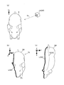
- FIG. 3A is a diagram for explaining a specific example of the shooting direction Sc.
- the vertical direction Sv is indicated by an arrow.
- the photographing direction Sc in the specific example of FIG. 3A is a direction intersecting the vertical direction Sv.
- a specific example is assumed in which the animal A is photographed by the image capturing unit 101 (depth camera 30) from the upper left direction when viewed from the animal A.
- FIG. 3B is a diagram for explaining a specific example of the animal image GA.
- the animal image GA is a three-dimensional image displayed in the XYZ space.
- An animal image GA can be obtained by executing the curved surface approximation process a plurality of times on the image captured by the image capturing unit 101.
- the animal image GA is rotated so that the vertical direction in the real space coincides with the Z-axis direction in the XYZ space based on the tilt information at the time of shooting. Further, the animal image GA is rotated so that the longitudinal direction coincides with the Y-axis direction. Specifically, the animal image GA is rotated so that the animal's head faces the positive direction of the Y-axis.
- the animal image GA is a point cloud image (point cloud data). Therefore, for example, the orientation of the animal head in the animal image GA can be specified by using principal component analysis.
- the configuration described in JP-A-2014-44078 can be adopted.
- the animal image GA represents an animal that is partially deficient.
- an animal image GA in the case where the animal A is photographed from the upper left direction when viewed from the animal A (similar to the specific example of FIG. 3A) is assumed.
- the animal image GA represents an animal in which the lower part of the right half of the body is missing.
- the animal image GA represents an animal in which the back side of the boundary portion L is missing when viewed in the photographing direction Sc.
- the carcass model image GM is an image showing the whole animal (however, excluding internal organs and the like) (see FIG. 6 (a) described later).
- the weight of the carcass is estimated by matching the outer edge of the carcass model image GM with the outer edge of the animal image GA (hereinafter referred to as "inverse proportion X").
- inverse proportional X when the body part of the animal represented by the animal image GA is missing, the outer edges of each image cannot be accurately matched, and it may be difficult to estimate the weight of the carcass with high accuracy. ..
- the weight estimation device 100 of the present embodiment adopts a configuration capable of generating (estimating) the entire image GW from the animal image GA.
- the whole image GW represents the whole animal. Therefore, by matching the outer edge of the carcass model image GM with the outer edge of the overall image GW and estimating the weight of the carcass, the above-mentioned inconvenience is suppressed as compared with the inverse proportion X.
- the above configuration will be described in detail below.
- FIG. 4 (a) and 4 (b) are diagrams for explaining a configuration (shape specifying portion 104) for specifying the spine curve S.
- FIG. 4A assumes a case where the animal image GA is viewed from the Z-axis direction, as in FIG. 3C. Further, FIG. 4A shows a plurality of vertices P (including Pn) constituting the spine curve S. By specifying the coordinates of each vertex P, the spine curve S is substantially specified.
- FIG. 4B shows a cross section of the animal image GA parallel to the Y-axis and the Z-axis (parallel to the YZ plane). Specifically, the cross section shown in FIG. 4B assumes the case where the animal image GA is cut at the position where the X coordinate is the numerical value “n” (see also FIG. 4A).
- FIG. 4B shows an excerpt of an animal image GA portion (outer edge) representing the surface of the back of the animal from each part of the animal.
- Each vertex P constituting the spine curve S of the animal is usually the point (vertex of the cross section) whose Z coordinate is the largest among the cross sections parallel to the YZ plane of the animal image GA. Therefore, the weight estimation device 100 identifies the apex of the cross section of the animal image GA as the apex P constituting the spine curve S.
- the coordinates of the vertices of the cross section parallel to the YZ plane whose X coordinate is the numerical value "n" are (n, m, Zmax).
- the coordinates (n, m, Zmax) are specified as the coordinates of the vertex P.
- the back muscle curve S is specified.
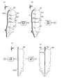
- 5 (a) to 5 (d) are diagrams for explaining a configuration (information generation unit 106) that generates an overall image GW (information for estimation) based on the spine curve S. 5 (a) to 5 (d) assume the case where the animal image GA is viewed from the Z-axis direction, as in the case of FIGS. 3 (c) and 4 (a).
- FIG. 5A is a diagram for explaining a specific example of the animal image GA used for generating the whole image GW.
- the weight estimation device 100 generates the entire image GW by executing the straightening process, the excision process, the selection process, and the generation process on the animal image GA.
- FIG. 5A shows an excerpt of the round slice image Gc4 from the round slice image Gc1 from each of the above round slice images Gc.
- the round slice image Gc1 is an image including the apex P1 of the spine curve S.
- the round slice image Gc2 is an image including the apex P2 of the spine curve S
- the round slice image Gc3 is an image including the apex P3 of the spine curve S
- the round slice image Gc4 is an image of the spine curve S. It is an image including the vertex P4.
- each round slice image Gc constituting the animal image GA includes a round slice image Gc that is not parallel to the YZ plane.
- the weight estimation device 100 of the present embodiment executes a linearization process on the above animal image GA.
- FIG. 5B is a diagram for explaining a specific example of the animal image GA in which the linearization process has been executed.
- the specific example of FIG. 5 (b) assumes a case where the linearization process is executed on the animal image GA of FIG. 5 (a).
- the directions of all the round slice images Gc of the animal image GA are parallel to the YZ plane, and the spine curve S seen from the Z axis direction is parallel to the Y axis direction.
- the position and orientation are adjusted.
- it is sufficient that the spine curve S viewed from the Z-axis direction is adjusted parallel to the Y-axis direction, and the specific content is not limited to the above examples.
- the weight estimation device 100 (half body selection unit 105) executes the selection process.
- the selection process one of the right and left halves of animal A is selected as the specific halves.
- the animal image GA is cut into two images (an image showing the right half of the body and an image showing the left half of the body) in the Z-axis direction along the back muscle curve S.
- the selection process of the above two images, the half body represented by the larger image is selected as the specific half body.
- the selection process is executed for the animal image GA shown in FIG. 5 (b).
- the animal image GA substantially the entire left half of the animal A is represented.
- FIG. 5B the portion of the right half of the body of animal A on the right side of the boundary portion L as viewed from animal A is not represented (missing) in the animal image GA.
- the left half of the body is selected as the specific half of the body.
- the weight estimation device 100 executes the excision process on the animal image GA.
- FIG. 5C is a diagram for explaining a specific example of the animal image GA in which the excision process has been executed.
- the excision process of each half of the animal A, the portion representing the half body not selected for the above-mentioned specific half body is excised from the animal image GA.
- the animal image GA for which the excision process has been performed may be referred to as "half-body image Gax".
- a half-body image Gax is assumed when the excision process is executed on the animal image GA shown in FIG. 5 (b).
- the half-body image Gax is an image showing the left half of the animal A.
- the cross section generated by the excision process may be described as "cross section Lx".
- the cross section Lx is substantially parallel to the XZ plane.
- the outer edge of the cross section Lx includes the entire spine curve S.
- the weight estimation device 100 executes the generation process after executing the excision process.
- the whole image GW is generated by the above generation processing.
- FIG. 5D is a diagram for explaining the entire image GW generated by the generation process.
- the entire image GW is generated from the half-body image Gax shown in FIG. 5 (c). That is, it is assumed that the whole image GW is generated from the half-body image Gax representing the left half of the animal A.
- the weight estimation device 100 when the weight estimation device 100 generates the whole image GW from the half-body image Gax representing the specific half-body of the animal A, the weight estimation device 100 specifies an image (hereinafter referred to as "half-body image Gay") that is in contrast to the half-body image Gax. It is generated as an image showing the half body on the opposite side of the half body.
- the image obtained by combining the above half-body image Gax and the half-body image Gay is stored as the whole image GW.
- the half-body image Gax shown in FIG. 5 (c) represents the left half of the animal A.
- the half-body image Gay representing the right half of the animal A is generated.
- the half-body image Gay is a face contrast with the half-body image Gax with respect to a plane passing through the cross section Lx of the half-body image Gax and parallel to the XZ plane.
- the half-body image Gay includes a cross section Ly.
- the cross-section Ly of the half-body image Gay is substantially congruent with the cross-section Lx of the half-body image Gay.
- the half-body image Gay is generated at a position where the cross-section Ly substantially coincides with the cross-section Lx of the half-body image Gax.
- FIG. 5D is a specific example of the entire image GW when the left half of the animal A is selected as the specific half.
- the animal image GA taken from the left half body side of the animal A is acquired, the left half body of the animal A is selected as the specific half body.
- the animal image GA taken from the right half body side of the animal A is acquired, the right half body of the animal A can be selected as the specific half body.
- a half-body image Gax showing the right half of the animal A is generated. Further, in the above case, a half-body image Gay representing the left half-body is generated from the half-body image Gax. That is, the half-body image Gay representing the left half of the body is estimated from the half-body image Gax representing the right half of the animal A, and the whole image GW representing the entire animal A is generated.
- the second direction for example, the right half body side
- the whole image GW is generated even when the animal is photographed.
- the weight related to the animal is estimated from the whole image GW. That is, according to the present embodiment, the weight related to the animal can be estimated regardless of whether the animal is photographed from either the first direction or the second direction.
- the above configuration has an advantage that the degree of freedom in the imaging direction is improved as compared with the configuration in which the weight related to the animal can be estimated only from the image of the animal captured from, for example, a specific one direction.
- the case where an image of an animal in the posture in which the back muscle curve has the first shape (first posture) is acquired and the case where the back muscle curve has the second shape are obtained.
- the spine curve can be straightened when viewed from the Z-axis direction in either case where an image of an animal in a posture (second posture) is acquired. That is, the whole image GW (estimation information) is generated regardless of the posture of the animal, and the weight of the animal can be estimated. Therefore, for example, a posture in which the weight related to the animal can be estimated from the image of the animal in the first posture, but the weight related to the animal cannot be estimated from the image of the animal in the second posture. There is an advantage that the degree of freedom is improved.
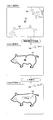
- 6 (a) to 6 (c) and 6 (d-1) to 6 (d-3) show specific examples of the configuration (weight estimation unit 108) for calculating the weight of the carcass of animal A. It is a figure for doing.
- the weight estimation device 100 calculates (estimates) the weight of the carcass of the animal A by executing the weight estimation process.
- FIG. 6A is a conceptual diagram of the carcass model image GM.
- the carcass model image GM is an image showing the whole animal.
- the carcass model image GM is an image of an animal from which parts (internal organs, etc.) not included in the carcass have been removed.
- the carcass model image GM is an image (standardized image) of an animal having a straight spine curve, similarly to the whole image GW.
- the carcass model image GM of the present embodiment includes the model image Gm1 to the model image Gm7. Each model image Gm corresponds to any part of the whole image GW.
- FIG. 6C is diagrams for explaining a portion of the entire image GW corresponding to the model image Gm.
- the portion of the entire image GW corresponding to the model image Gm1 is described as “partial image Gw1”.
- the part of the whole image GW corresponding to the model image Gm2 is "partial image Gw2”
- the part of the whole image GW corresponding to the model image Gm3 is “partial image Gw3”
- the part of the whole image GW corresponding to the model image Gm5 is the "partial image Gw5"
- the part of the whole image GW corresponding to the model image Gm6 is the "partial image Gw6”
- the part of the whole image GW corresponding to the model image Gm7 is the whole.
- the part of the image GW is described as "partial image Gw7”.
- the model image Gm is fitted (enlarged or reduced) according to the partial image Gw to which the model image Gm corresponds. Specifically, the model image Gm is fitted so that the outer edge of the model image Gm coincides with the outer edge of the partial image Gw.
- the carcass model image GM is composed of seven model images m, but the carcass model image GM may be composed of more than seven model images m, or less than seven model images m. It may be composed of.
- 6 (d-1) to 6 (d-3) are diagrams for explaining a specific example in the case of fitting the carcass model image GM to the whole image GW.
- the model image Gm4 of each model image Gm is fitted.
- the partial image Gw4 assumes that the height in the Z-axis direction is Zw and the width in the Y-axis direction is Yw.
- the model image Gm4 assumes that the height in the Z-axis direction is Zm and the width in the Y-axis direction is Ym.
- the weight estimation device 100 enlarges the model image Gm4 so that the height in the Z-axis direction is Zw and the width in the Y-axis direction is Yw (in some cases). Shrinks).
- the weight estimation device 100 specifies (calculates) the vertical magnification "Zw / Zm” and the horizontal magnification "Yw / Ym” by pattern matching with the cross section of the carcass model image GM using the shape of the partial image Gw4. )do. Further, the weight estimation device 100 changes the height of the model image Gm4 according to the vertical magnification "Zw / Zm", and changes the width of the model image Gm4 according to "Yw / Ym".
- the weight estimation device 100 calculates the volume of the carcass model image Gm after finishing the fitting of the carcass model image GM (all model images Gm). Further, the weight estimation device 100 estimates the product of the volume of the carcass model image GM after fitting and the average density of the carcasses of the animal as the weight of the carcasses of the animal.
- the weight estimation device 100 of the present embodiment displays the estimated weight of the carcass on the display unit 102 (head-mounted display 20).
- FIG. 7 (a) to 7 (b) are diagrams for explaining various images displayed on the display unit 102.
- the display unit 102 of the present embodiment is a head-mounted display, and the user can check the scenery actually viewed and the screen of the display unit 102 at once.
- FIG. 7A is a simulated view of the screen M1 displayed before the weight estimation process is executed.
- the image captured by the image capturing unit 101 is displayed on the display unit 102 in real time. Further, the shooting direction of the image shooting unit 101 substantially coincides with the line-of-sight direction of the user.
- the specific example of FIG. 7A assumes a case where the animal A is located below the center of the user's visual field (hereinafter referred to as “visual field center”).
- the animal image GA is displayed below the center of the screen M1.
- the animal B is located on the upper right side of the center of the visual field of the user
- the animal image GB is displayed on the upper right side of the center of the screen M1.
- the animal image GA is extracted and acquired from the image (hereinafter referred to as “landscape image”) taken by the image capturing unit 101.
- the animal image GA is specified from the landscape image by the region expansion method, and the animal image GA is acquired.
- the region expansion method it is necessary to specify the pixels included in the animal image GA as seed pixels.
- the method for specifying the seed pixel will be described in detail.
- the screen M1 includes a point image GP.
- the point image GP is fixedly displayed on the screen M1. That is, among the images displayed on the screen M1, the landscape image changes (moves) according to the shooting direction (user's visual field direction), but the position of the point image GP on the screen M1 moves according to the shooting direction. do not.
- the pixels of the landscape image (including the animal image GA) in which the point image GP is located are specified as seed pixels. Therefore, for example, when estimating the weight of the animal A, the shooting direction (the line-of-sight direction of the user) is changed so that the point image GP is located at the animal image GA. For example, in the specific example of FIG. 7A, the weight of the animal A is increased by moving the line-of-sight direction of the user (moving the line-of-sight downward) so that the animal image GA moves in the direction of the arrow Y. Presumed.
- FIG. 7B is a simulated view of the screen M2 displayed during the execution of the weight estimation process.
- the screen M2 is displayed immediately after the animal image GA is identified by, for example, the region expansion method.
- the screen M2 is configured to include a landscape image including an animal image GA and a point image GP, similarly to the screen M1.
- the weight estimation process is executed according to the shooting operation of the user. Specifically, when a shooting operation is performed on the weight estimation device 100, an animal image in which the point image GP is located at the time of the shooting operation is acquired, and the weight estimation process is executed.
- the trigger for executing the weight estimation process can be set as appropriate.
- the weight estimation process may be automatically executed when the point image GP moves onto the animal image GA.
- FIG. 7C is a simulated view of the screen M3 displayed immediately after the weight estimation process is completed.
- the screen M3 is configured to include the animal image GA as well as the screen M1 and the screen M2.
- the screen M3 is configured to include a weight image Gn.
- the weight image Gn displays the weight of the carcass calculated by the above-mentioned weight estimation process. For example, in the specific example of FIG. 7C, it is assumed that the weight of the carcass is estimated to be "75 kg".
- the weight image Gn is displayed superimposed on the animal image (GA in the example of FIG. 7 (c)) used for estimating the weight.
- the weight-estimated animal animal image used in the weight estimation process
- the position where the weight image Gn is displayed can be changed as appropriate.
- the body weight (living body weight) of the whole animal may be estimated.
- the body weight is displayed on the weight image Gn.
- a configuration in which both the biological weight of the animal and the weight of the carcass are estimated is adopted, a configuration in which both the biological weight and the weight of the carcass are displayed on the weight image Gn is preferable.
- the point image GP is hidden when the weight end processing is completed. That is, when the weight image Gn is displayed, the point image GP is hidden.
- the inconvenience that the point image GP and the weight image Gn overlap and the weight image Gn becomes difficult to see in the point image GP is suppressed.
- the point image GP may be continuously displayed when the weight end processing is completed.
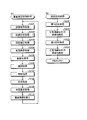
- FIG. 8A is a flowchart of the weight estimation control process executed by the weight estimation device 100.
- the weight estimation device 100 executes the weight estimation control process at a predetermined time interval (interrupt cycle), for example. However, the execution trigger of the weight estimation control process can be changed as appropriate.
- the weight estimation device 100 executes the image acquisition process (S101).
- the image acquisition process an animal image is acquired from a distance image (a landscape image including an animal image) taken according to the shooting operation.
- a distance image a landscape image including an animal image
- the above-mentioned region expansion method is used.
- the animal image is converted into real coordinates (XYZ coordinates).
- the weight estimation device 100 executes the curved surface approximation process (S102).
- the surface of animals such as pigs is usually smooth.
- the surface of the animal image acquired in step S102 is approximated (fitted) to a smooth curved surface. The details of the curved surface approximation processing will be described later with reference to FIG. 8 (b).
- the weight estimation device 100 executes the rotation correction process (S103).
- the rotation correction process the orientation of the animal image in the Z-axis direction is adjusted (rotated) using the above-mentioned tilt information. Further, in the rotation correction process, the orientation of the animal image in the XY plane (horizontal plane) is adjusted by using the above-mentioned principal component analysis.
- the weight estimation device 100 executes the spine identification process (S104).
- the back muscle identification process the back muscle curve in the animal image is specified (see FIG. 4A).
- the weight estimation device 100 executes the linearization process (S105). In the straightening process, the animal image is adjusted (deformed) so that the spine curve becomes a straight line when viewed from the Z-axis direction (see FIG. 5 (b)).
- the weight estimation device 100 executes the selection process (S106).
- the selection process assuming that the animal image GA is cut into two images in the Z-axis direction by the spine curve, the half body represented by the larger image of the two images is selected as the specific half body. ..
- the weight estimation device 100 executes the excision process (S107). In the above excision process, the portion representing the half body not selected as the specific half body is excised from the animal image (see FIG. 5C). After executing the excision process, the weight estimation device 100 executes the generation process (S108). In the generation process, the whole image GW is generated from the animal image (half-body image) (see FIG. 5D).
- the weight estimation device 100 executes the weight estimation process (S109).
- the weight of the carcass of the animal is estimated (calculated) from the whole image GW generated by the above-mentioned generation process.
- the carcass model image GM was fitted so that the outer edge of the overall image GW coincided with the outer edge of the carcass model image GM (see FIGS. 6 (d-1) to 6 (d-3)) and fitted.
- the volume of the carcass model image GM is obtained. Further, the product of the average density stored in advance and the volume of the carcass model image GM is calculated as the weight of the carcass.
- the weight estimation device 100 After executing the weight estimation process, the weight estimation device 100 causes the display unit 102 to display the weight image Gn (see FIG. 7C) (S110). After displaying the weight image Gn, the weight estimation device 100 returns the process to step S101.
- FIG. 8B is a flowchart of the curved surface approximation process (S102 in FIG. 8A).
- the weight estimation device 100 executes the first approximation process (S201).
- the first approximation process polynomial approximation function curve fitting using the least squares method is executed with each point constituting the surface of the animal image (point cloud image) as a sample point.
- the curved surface fitting method is not limited to the polynomial approximation function curved surface fitting, and an appropriate method can be adopted.
- the animal image of the animal whose weight is estimated may include an image representing another animal (hereinafter referred to as "noise image"). If the animal image for estimating the weight includes a noise image, the inconvenience that the weight is not estimated accurately may occur.
- the weight estimation device 100 deletes an image not included in the approximate curved surface representing the surface of the animal to be photographed as a noise image after executing the first approximation process (S202). That is, a point cloud deviating from one approximate curved surface representing the surface of the animal to be photographed is deleted as a point cloud representing another animal or the like. With the above configuration, the above-mentioned inconvenience is suppressed.
- the weight estimation device 100 executes the second approximation process (S203).
- the polynomial approximation function curve fitting is executed on the animal image as in the first approximation process.
- the polynomial approximation function curve fitting is executed using a higher-order polynomial as compared with the first approximation process.
- the surface of the animal to be photographed is extracted with higher accuracy than in the first approximation processing. Therefore, if the noise image cannot be completely deleted in step S202, the noise image is extracted in the second approximation process as an image different from the surface of the animal to be photographed.
- the weight estimation device 100 deletes the noise image after executing the second approximation process (S204).
- the noise image is deleted from the animal image with high accuracy as compared with the configuration in which only the first approximation processing is executed out of the first approximation processing and the second approximation processing. Therefore, there is an advantage that the weight of the animal to be photographed is estimated with high accuracy.
- the configuration may be such that only the second approximation process of the first approximation process and the second approximation process is executed (hereinafter, “inverse proportion Y”).
- inverse proportion Y the processing load of the second approximation process tends to be larger than the processing load of the first approximation process.
- the noise image is finally deleted. From the above circumstances, there is a circumstance that the smaller the noise image to be subjected to the second approximation processing, the more suitable it is.
- the first approximation process is executed prior to the second approximation process, and the noise image extracted by the first approximation process is deleted. Therefore, there is an advantage that the noise image to be the target of the second approximation processing can be made smaller as compared with the inverse proportional Y.
- the shape of the defective animal part is estimated in the animal image, and the whole image GW is generated.
- the possibility of an error between the estimated shape and the actual shape cannot be completely ruled out. That is, an error may occur between the shape of the animal represented by the whole image GW and the shape of the actual animal. Therefore, if an animal image showing the entire back of an animal can be taken, the whole image GW is better when the carcass model image GM is fitted based on the animal image (an image showing the actual shape of the animal).
- the carcass model image GM is fitted based on (an image showing the estimated shape of the animal)
- there is a circumstance that the weight related to the animal can be easily estimated with high accuracy.
- the weight estimation device 100 of the second embodiment fits the carcass model image GM based on the animal image when the animal image representing the entire back of the animal can be captured.
- the carcass model image GM is fitted based on the whole image GW.
- the weight estimation device 100 of the second embodiment acquires an animal image, it determines whether or not the animal has been photographed from the vertical direction based on the above-mentioned inclination information. Specifically, when the tilt information is within a predetermined range (0 degree ⁇ ⁇ ), it is determined that the animal was photographed from the vertical direction. On the other hand, if the tilt information is out of the range, it is determined that the animal was not photographed from the vertical direction. When an animal is photographed from the vertical direction, it is presumed that the animal image includes an image showing the entire back.
- the carcass model image GM is fitted based on the animal image to estimate the weight of the animal.
- the weight estimation device 100 determines that the animal has not been photographed from the vertical direction, the weight estimation device 100 generates an overall image GW from the animal image (similar to the first embodiment). Further, the weight estimation device 100 fits the carcass model image GM based on the whole image GW to estimate the weight related to the animal.
- the weight related to the animal can be estimated as in the first embodiment. Further, when it is determined that the animal is photographed from the vertical direction, the carcass model image GM is fitted based on the animal image. Therefore, the effect of being able to estimate the weight of an animal with high accuracy is particularly remarkable.
- a configuration is adopted in which whether the carcass model image GM is fitted based on the animal image or the carcass model image GM is fitted based on the whole image GW is automatically selected.
- the shape of the animal image may be confirmed by the user, and the user may (manually) select the shape according to the shape of the animal image.
- the weight estimation device (100) of this embodiment includes an image acquisition unit (101) that acquires an image of an animal, a shape identification unit (104) that specifies the shape (back muscle curve) of a predetermined part of the animal from the image, and a predetermined part.
- An information generation unit (106) that generates estimation information (overall image GW) used for estimating the weight of an animal based on the shape of the animal, and a weight estimation unit (108) that estimates the weight based on the estimation information.
- the information generation unit can generate estimation information when a first image (animal image GA) obtained by photographing an animal from a first direction (for example, the left half of the body side) is acquired.
- the predetermined part of the animal is the back muscle of the animal, and one of the right half body located on the right side and the left half body located on the left side of the back muscle when viewed from the animal is specified as a specific half body.
- the half-body selection unit (105) is provided, and the information generation unit estimates the shape of the half-body that is not selected for the specific half-body from the shape of the specific half-body (see FIG. From the shape of the specific half body, information indicating the shape of the entire animal can be generated as estimation information (see FIG. 5D). According to the above aspect, the same effect as that of the above-mentioned first aspect can be obtained.
- the weight estimation device of the third aspect includes an information storage unit that stores carcass model information (carcass model image GM) indicating the shape of the carcass, and the weight estimation unit responds to the shape of the animal indicated by the estimation information. Based on the carcass shape indicated by the deformed carcass model information, the weight of the carcass of the animal is estimated (see FIGS. 6 (d-1) to 6 (d-3)).
- carcass model information carcass model image GM
- the information generation unit generates estimation information when a third image of an animal in the first posture (posture in which the spine curve has the first shape) is acquired.
- a fourth image of an animal in a second posture a posture in which the spine curve has a second shape
- the weight of the animal can be estimated from the image of the animal in the first posture, but the weight of the animal cannot be estimated from the image of the animal in the second posture. It has the advantage of increasing the degree of freedom of posture in which the weight of the animal can be estimated.
- the weight estimation device (100) of the fifth aspect has an image capturing unit (101) that can be fixed at a specific position when viewed from the user and can photograph an animal located in the line-of-sight direction of the user, and an image capturing unit. It is provided with a display unit (102) which is a head-mounted display capable of displaying an image captured by the image acquisition unit, and the image acquisition unit acquires an image captured by the image acquisition unit. According to the above aspect, there is an advantage that it is not necessary to hold an image capturing unit in the hand when photographing an animal. Further, in the weight estimation device of the sixth aspect, the image acquisition unit acquires a distance image including information indicating the distance to the animal.
- the program of this aspect includes an image acquisition process (S101 in FIG. 8A) for acquiring an image of an animal on a computer (10) and a shape for specifying the shape of a predetermined part of the animal from the image.
- Specific processing S104 in FIG. 8A
- information generation processing S108 in FIG. 8A
- a program that executes a weight estimation process S109 in FIG. 8A) that estimates the weight based on information. In the information generation process, a first image of an animal taken from a first direction is acquired.
- 100 ... Weight estimation device, 101 ... Imaging unit, 102 ... Display unit, 103 ... Image acquisition unit, 104 ... Shape identification unit, 105 ... Half body selection unit, 106 ... Information generation unit, 107 ... Carcass model storage unit, 108 ... Weight estimation unit.
Abstract
動物に関する重量が推定可能となる撮影方向の自由度が向上する重量推定装置を提供する。動物の画像を取得する画像取得部と、画像から動物の所定部位の形状を特定する形状特定部と、所定部位の形状に基づいて、動物に関する重量の推定に用いる推定用情報を生成する情報生成部と、推定用情報に基づいて、重量を推定する重量推定部と、を具備する構成において、情報生成部は、第1方向(例えば、左半身側)から動物を撮影した第1画像(動物画像GA)が取得された場合と、第1方向と相違する第2方向(例えば、右半身側)から動物を撮影した第2画像が取得された場合と何れであっても、推定用情報を生成可能である。
Description
本発明は、重量推定装置及びプログラムに関する。
従来、家畜などの動物の体重は、体重計により計測される。しかし、体重計の上で動物が静止しない場合、体重が正確に計測されない問題があった。この問題を解決する構成として、特許文献1には、予め定められた撮影方向から動物を撮影し、撮影された画像から当該動物の体重を計測(推定)する構成が記載される。以上の構成によれば、体重計の上で動物を静止させる必要がないため、上述の問題が抑制される。
しかし、特許文献1の構成では、動物の体重が推定できる撮影方向の自由度が低いという問題があった。具体的には、特許文献1の構成では、第1方向(真上方向)から動物を撮影した場合のみ当該動物の体重が推定でき、第1方向とは相違する第2方向から撮影した場合は当該動物の体重を推定できない。以上の事情を考慮して、本発明は、動物に関する重量が推定可能となる撮影方向の自由度を向上することを目的とする。
以上の課題を解決するために、本発明の重量推定装置は、動物の画像を取得する画像取得部と、画像から動物の所定部位の形状を特定する形状特定部と、所定部位の形状に基づいて、動物に関する重量の推定に用いる推定用情報を生成する情報生成部と、推定用情報に基づいて、重量を推定する重量推定部と、を具備し、情報生成部は、第1方向から動物を撮影した第1画像が取得された場合に推定用情報を生成可能であるとともに、第1方向と相違する第2方向から動物を撮影した第2画像が取得された場合にも推定用情報を生成可能である。
以上の構成によれば、第1方向から動物を撮影した第1画像が取得された場合に当該動物に関する重量が推定可能であるとともに、第1方向と相違する第2方向から動物を撮影した第2画像が取得された場合にも当該動物に関する重量が推定できる。したがって、特許文献1の構成と比較して、動物に関する重量が推定可能となる撮影方向の自由度が向上する。
本発明によれば、動物に関する重量が推定可能となる撮影方向の自由度が向上する。
<第1実施形態>
図1は、重量推定装置1のハードウェア構成図である。図1に示す通り、重量推定装置1は、コンピュータ10、ヘッドマウントディスプレイ20およびデプス(深度)カメラ30を含む。以上の各構成は、通信可能に接続される。
図1は、重量推定装置1のハードウェア構成図である。図1に示す通り、重量推定装置1は、コンピュータ10、ヘッドマウントディスプレイ20およびデプス(深度)カメラ30を含む。以上の各構成は、通信可能に接続される。
コンピュータ10は、CPU(Central Processing Unit)11、ROM(Read Only Memory)12、RAM(Random access memory)13およびHDD(Hard Disk Drive)14を含んで構成される。本実施形態のコンピュータ10は、持運び可能なコンピュータ(例えば、ノートパソコン)が採用される。ただし、ディスクトップパソコンをコンピュータ10として採用してもよい。
コンピュータ10のHDD14は、重量推定プログラムPGを含む各種のデータを記憶する。CPU11は、重量推定プログラムPGを実行することで、後述の各種の機能(重量推定部108など)を実現する。RAM13は、例えばCPU11がプログラムを実行する際に参照する各種の情報を一時的に記憶する。また、ROM12は、各種の情報を不揮発的に記憶する。なお、重量測定プログラムPGがHDD14以外に記憶される構成としてもよい。
ヘッドマウントディスプレイ20は、利用者の頭部に固定可能であり、周知なヘッドマウントディスプレイが適宜に採用され得る。例えば、ヘッドマウントディスプレイ20として、小型液晶画面およびハーフミラーを含むものが採用され得る。以上の小型液晶画面は各種の画像を表示可能であり、小型液晶画面に表示された画像は、ハーフミラーに反射して利用者に視認される。以上の構成では、ハーフミラー越しに利用者が景色を見た場合、小型液晶画面に表示された画像が景色に重ねて視認される。ただし、ヘッドマウントディスプレイ20は以上の例に限定されない。
デプスカメラ30は、被写体までの距離を示す深度情報を含む距離画像(3次元画像)を生成する。例えば、距離画像としては、LIDAR(Light Detection and Ranging、Laser Imaging Detection and Ranging)技術により撮影された点群画像が想定される。また、デプスカメラ30は、傾きセンサが設けられる。以上の傾きセンサは、鉛直方向に対する撮影方向の傾きの大きさを検出する。
図1に示す通り、デプスカメラ30は、ヘッドマウントディスプレイ20に固定される。したがって、利用者がヘッドマウントディスプレイ20を頭部に装着した際に、利用者から見て特定位置でデプスカメラ30が固定される。具体的には、デプスカメラ30は、撮影方向が利用者の視線方向に略一致する位置に固定される。
以上の構成では、利用者が視認する景色がデプスカメラ30で撮影される。したがって、利用者は、自身の視野内に動物が位置する様に、視線方向(顔の向き)を動かすことにより、当該動物を撮影できる。なお、デプスカメラ30を利用者が手に持ち、動物の画像が撮影される構成を採用してもよい。ただし、以上の構成では、利用者が両手を自由に使えない。一方、本実施形態の構成では、利用者が両手を自由に使うことができるという利点がある。
デプスカメラ30で撮影された画像は、ヘッドマウントディスプレイ20(小型液晶画面)に表示される。具体的には、デプスカメラ30で撮影された画像は、リアルタイムでヘッドマウントディスプレイ20に表示される。以上の構成では、デプスカメラ30で撮影された画像をリアルタイムに利用者が確認可能である。ただし、デプスカメラ30で撮影された画像がリアルタイムに表示されない構成を採用してもよい。
デプスカメラ30で撮影された動物の画像は、コンピュータ10に入力される。コンピュータ10は、重量推定プログラムPGを実行することにより、入力された画像から動物に関する重量(例えば、枝肉の重量)を推定する。以上の機能について、以下で詳細に説明する。
図2は、重量推定装置100の機能ブロック図である。重量推定装置100は、画像撮影部101、表示部102、画像取得部103、形状特定部104、半身選択部105、情報生成部106、枝肉モデル記憶部107および重量推定部108を含んで構成される。CPU11が重量推定プログラムPGを実行することで、以上の各機能が実現される。
画像撮影部101は、動物の画像を撮影可能である。具体的には、画像撮影部101は、利用者から見て特定位置で固定され、当該利用者の視線方向に位置する動物を撮影可能である。例えば、デプスカメラ30が画像撮影部101として機能する。表示部102は、画像撮影部101が撮影した画像を含む各種の画像を表示可能である(後述の図7(a)参照)。例えば、ヘッドマウントディスプレイ20が表示部102として機能する。
画像取得部103は、動物の画像(後述の図3(b)参照)を取得する。具体的には、画像撮影部101が撮影した画像には、動物の画像の他に背景などの画像が含まれる。画像取得部103は、画像撮影部101が撮影した画像から、1匹の動物を表す画像を抜粋して取得する。画像取得部103が取得した動物の画像は、当該動物に関する重量を推定するのに用いられる。
本実施形態の画像取得部103は、画像撮影部101が撮影した画像から動物の画像を領域拡張法により取得する。具体的には、画像取得部103は、画像撮影部101が撮影した画像において、1個の画素を種子画素として特定する。画像撮影部101が撮影した画像に含まれる各画像(オブジェクト)のうち、自身を構成する各画素に種子画素が含まれる画像が画像取得部103により取得される。以上の構成では、動物の画像を構成する各画素の何れかを種子画素として特定することにより、画像撮影部101が撮影した画像から当該動物の画像が抜粋して取得される。
より具体的には、画像取得部103は、種子画素を特定すると、所定のラベルを種子画素に付与する。画像取得部103は、種子画素の近傍の画素のうち、予め定められた条件を満たす画素に共通のラベルを付与する。また、共通のラベルが付与された画素の近傍の画素についても、上述の条件を満たす場合は当該ラベルが付与される。以上の処理は、ラベルを付与する画素が無くなるまで繰返される。画像取得部103は、共通のラベルが付与された各画素で構成される画像を、動物の画像として取得する。なお、種子画素の特定方法については、後述の図7(a)から図7(c)を用いて詳細に説明する。
以下、説明のため、画像取得部103が取得した動物の画像を「動物画像」と記載する場合がある。また、上述の傾きセンサが検出した鉛直方向に対する撮影方向の傾きの大きさを「傾き情報」と記載する場合がある。重量推定装置100は、動物画像の撮影時における傾き情報を、当該動物画像に対応させて記憶する。以上の傾き情報は、動物画像の向きを調整(補正)する際に用いられる。
形状特定部104は、動物画像から動物の所定部位の形状を特定する。本実施形態の形状特定部104は、所定部位として動物の背筋の形状を特定する。以下、動物の背筋の形状を単に「背筋曲線」という。背筋曲線の特定方法の具体例は、後述の図4(a)および図4(b)を用いて詳細に説明する。
半身選択部105は、動物から見て背筋より右側に位置する右半身および左側に位置する左半身のうちの一方を特定半身として選択する。詳細には後述するが、撮影方向によっては、動物全体が撮影されない場合がある。以上の場合、体の一部が欠損した動物を表す動物画像が生成される(図3(b)参照)。例えば、右半身側から動物を撮影すると、左半身の一部(または全て)が欠損した動物を表す動物画像が生成される。半身選択部105は、動物の各半身のうち、より広範囲が撮影された半身を特定半身として選択する。
情報生成部106は、背筋曲線(所定部位の形状)に基づいて、動物に関する重量の推定に用いる推定用情報を生成する。本実施形態の推定用情報には、後述の図5(d)に示す全体画像GWが含まれる。全体画像GWは、動物全体を表す画像であり、画像取得部103が取得した動物画像(動物の一部が欠損した画像)から生成(推定)される。具体的には、動物画像から上述の特定半身を表す画像(後述の半身画像。図5(c)参照)が生成され、当該特定半身を表す画像から全体画像GWが生成される。
枝肉モデル記憶部107は、枝肉モデル画像GM(後述の図6(a)参照)を記憶する。枝肉モデル画像GMは、全体画像GWと同様に、動物の全体を表す画像である。ただし、枝肉モデル画像GMは、枝肉に含まれない部位(内蔵類など)を取り除いた動物の画像である。以上の枝肉モデル画像GMは、例えば、標準的な体形の動物をCT(Computed Tomography)撮影することにより得られる。
重量推定部108は、動物の全体画像GW(推定用情報)から当該動物に関する重量を推定する。具体的には、動物の枝肉の平均密度(kg/m3)が重量推定装置100に予め記憶される。重量推定装置100に記憶される枝肉の平均密度は、例えば、動物の枝肉の平均密度を実際に計測する実験を繰返し、各実験で得られた各計測値から決定され得る。例えば、各実験の各計測値の平均値が平均密度として決定され得る。
また、全体画像GWの外縁に枝肉モデル画像GMの外縁が一致する様に、枝肉モデル画像GMがフィッティング(拡大、縮小)される。重量推定部108は、フィッティングされた枝肉モデル画像GMの体積と動物の枝肉の平均密度との積を、当該動物に関する重量として推定する。
以上の通り、本実施形態では、本発明の「動物に関する重量」として「動物の枝肉の重量」が推定される構成を採用した。ただし、「動物に関する重量」として「動物の枝肉の重量」以外が推定される構成を採用してもよい。例えば、「動物に関する重量」として「内蔵等を含めた動物の体重」(生体重)が推定される構成が考えられる。
具体的には、動物(例えば豚)の生体重は、体重式から求められることが知られている(例えば、特開2019-45478号公報参照)。以上の体重式は、生体重、体長および胸囲の関係を示し、実験的に求められる。また、全体画像GWからは、動物の体長および胸囲が特定される。したがって、重量推定部108は、全体画像GWから特定した体長および胸囲に基づいて、体重式を用いて動物の生体重を算出(推定)できる。なお、動物の生体重および枝肉の重量の双方が推定される構成としてもよい。
以下、図3(a~c)、図4(a、b)、図5(a~d)、図6(a~c、d-1~d-3)および図7(a~c)を用いて、重量推定装置100の動作の具体例を説明する。なお、以下で説明する具体例では、重量を推定する動物Aとして「豚」の例を説明するが、重量が推定される動物は「豚」に限定されない。例えば、「牛」や「イルカ」などの動物に関する重量が推定される構成としてもよい。
図3(a)は、撮影方向Scの具体例を説明するための図である。図3(a)には、鉛直方向Svが矢印で示される。図3(a)の具体例における撮影方向Scは、鉛直方向Svに交差する方向である。具体的には、動物Aから見て左上方向から当該動物Aが画像撮影部101(デプスカメラ30)により撮影される具体例を想定する。
図3(b)は、動物画像GAの具体例を説明するための図である。図3(b)に示す通り、動物画像GAは、XYZ空間に表示される3次元画像である。画像撮影部101が撮影した画像に対して、曲面近似処理を複数回実行することで、動物画像GAが得られる。
動物画像GAは、撮影された時点における傾き情報に基づいて、実空間における鉛直方向がXYZ空間におけるZ軸方向に一致する様に回転される。また、動物画像GAは、長手方向がY軸方向と一致する様に回転される。具体的には、動物の頭部がY軸の正の方向を向く様に動物画像GAが回転される。動物画像GAは、点群画像(点群データ)である。したがって、例えば、主成分分析を用いて、動物画像GAにおける動物の頭部の向きが特定できる。なお、動物画像GAの向きを調整する構成としては、例えば、特開2014-44078号公報に記載の構成が採用され得る。
ところで、撮影方向によっては、動物の全体が撮影されない場合がある。以上の場合、動物画像GAは一部が欠損した動物を表す。例えば、図3(b)の具体例では、動物Aから見て左上方向から当該動物Aが撮影された場合(図3(a)の具体例と同様)の動物画像GAを想定する。動物画像GAは、右半身の下側が欠損した動物を表す。具体的には、図3(b)に示す通り、動物画像GAは、撮影方向Scへ見て境界部Lより奥側が欠損した動物を表す。
しかし、枝肉モデル画像GMは、動物の全体(ただし内臓等は除く)を表す画像である(後述の図6(a)参照)。仮に、動物画像GAの外縁に枝肉モデル画像GMの外縁を一致させることにより枝肉の重量が推定される構成(以下「対比例X」という)を想定する。以上の対比例Xでは、動物画像GAが表す動物の体部分が欠損している場合、各画像の外縁を正確に一致できず、枝肉の重量が高精度に推定され難くなるという不都合が生じ得る。
以上の事情を考慮して、本実施形態の重量推定装置100は、全体画像GWを動物画像GAから生成(推定)可能な構成を採用した。全体画像GWは、動物の全体を表す。したがって、全体画像GWの外縁に枝肉モデル画像GMの外縁を一致させ、枝肉の重量を推定することにより、対比例Xと比較して上述の不都合が抑制される。以上の構成について、以下で詳細に説明する。
図4(a)および図4(b)は、背筋曲線Sを特定する構成(形状特定部104)を説明するための図である。図4(a)は、図3(c)と同様に、Z軸方向から動物画像GAを見た場合を想定する。また、図4(a)には、背筋曲線Sを構成する複数の頂点P(Pnを含む)が示される。各頂点Pの座標を特定することで、背筋曲線Sが実質的に特定される。
図4(b)は、Y軸およびZ軸に平行(YZ平面に平行)な動物画像GAの断面を示す。具体的には、図4(b)に示す断面は、X座標が数値「n」の位置で動物画像GAを切断した場合を想定する(図4(a)も参照)。図4(b)には、動物の各部位のうち当該動物の背中の表面を表す動物画像GAの部分(外縁)が抜粋して示される。
動物の背筋曲線Sを構成する各頂点Pは、動物画像GAのYZ平面に平行な断面のうち、Z座標が最大の点(断面の頂点)になるのが通常である。したがって、重量推定装置100は、背筋曲線Sを構成する頂点Pとして動物画像GAの断面の頂点を特定する。
例えば、図4(b)の具体例では、X座標が数値「n」のYZ平面に平行な断面の頂点の座標が(n,m,Zmax)の場合を想定する。以上の場合、座標(n,m,Zmax)が頂点Pの座標として特定される。また、重量推定装置100は、X軸上の他の位置(X=n以外の位置)についても、YZ平面に平行な断面の頂点を頂点Pとして特定する。以上の構成では、背筋曲線Sが特定される。
図5(a)から図5(d)は、背筋曲線Sに基づいて全体画像GW(推定用情報)を生成する構成(情報生成部106)を説明するための図である。図5(a)から図5(d)は、図3(c)および図4(a)と同様に、Z軸方向から動物画像GAを見た場合を想定する。
図5(a)は、全体画像GWの生成に用いる動物画像GAの具体例を説明するための図である。重量推定装置100は、動物画像GAに対して、直線化処理、切除処理、選択処理および生成処理を実行することで、全体画像GWを生成する。
以下、説明のため、XY平面と垂直であり、且つ、XY平面に投影された背筋曲線Sと垂直な面状の画像を「輪切画像Gc」と記載する。動物画像GAは、例えば頂点Pと略同数の輪切画像Gcに区分される。ただし、図5(a)には、以上の各輪切画像Gcのうち、輪切画像Gc1から輪切画像Gc4を抜粋して示す。
図5(a)に示す通り、輪切画像Gc1は、背筋曲線Sのうち頂点P1を含む画像である。また、輪切画像Gc2は、背筋曲線Sのうち頂点P2を含む画像であり、輪切画像Gc3は、背筋曲線Sのうち頂点P3を含む画像であり、輪切画像Gc4は、背筋曲線Sのうち頂点P4を含む画像である。
図5(a)の具体例では、動物画像GAの背筋曲線SがZ軸方向から見て直線ではない場合を想定する。図5(a)から把握される通り、動物画像GAを構成する各輪切画像Gcには、YZ平面に対して平行ではない輪切画像Gcが含まれる。本実施形態の重量推定装置100は、以上の動物画像GAに対して、直線化処理を実行する。
図5(b)は、直線化処理が実行された動物画像GAの具体例を説明するための図である。図5(b)の具体例は、図5(a)の動物画像GAに対して直線化処理が実行された場合を想定する。直線化処理では、動物画像GAの全ての輪切画像Gcの向きがYZ平面に平行、且つ、Z軸方向からみた背筋曲線SがY軸方向に平行となる様に、各輪切画像Gcの位置および向きが調整される。なお、直線化処理は、Z軸方向から見た背筋曲線SがY軸方向に平行に調整されれば足り、具体的な内容は以上の例に限定されない。
以上の直線化処理を実行した後に、重量推定装置100(半身選択部105)は、選択処理を実行する。選択処理において、動物Aの右半身および左半身のうちの一方が特定半身として選択される。具体的には、動物画像GAを背筋曲線SでZ軸方向へ2個の画像(右半身を表す画像および左半身を表す画像)に切断した場合を想定する。選択処理では、以上の2個の画像のうち、より大きな画像で表される半身を特定半身として選択する。
例えば、図5(b)に示す動物画像GAに対して選択処理が実行された場合を想定する。動物画像GAでは、動物Aの左半身の略全体が表される。一方、図5(b)に示す通り、動物Aの右半身のうち、動物Aから見て境界部Lより右側の部位が、動物画像GAでは表されない(欠損している)。動物画像GAに対して選択処理が実行されると、左半身が特定半身として選択される。重量推定装置100は、選択処理を実行した後に、動物画像GAに対して切除処理を実行する。
図5(c)は、切除処理が実行された動物画像GAの具体例を説明するための図である。切除処理では、動物Aの各半身のうち、上述の特定半身に選択されなかった半身を表す部分が動物画像GAから切除される。以下、切除処理が実行される前の動物画像GAと区別するため、切除処理が実行された動物画像GAを「半身画像Gax」と記載する場合がある。
図5(c)の具体例は、図5(b)に示す動物画像GAに対して切除処理が実行された場合の半身画像Gaxを想定する。半身画像Gaxは、動物Aの左半身を表す画像である。なお、半身画像Gaxのうち、切除処理により生じた断面を「断面Lx」と記載する場合がある。図5(c)に示す通り、断面LxはXZ平面に対して略平行である。また、断面Lxの外縁には背筋曲線Sの全体が含まれる。重量推定装置100は、切除処理を実行した後に生成処理を実行する。以上の生成処理により、全体画像GWが生成される。
図5(d)は、生成処理により生成された全体画像GWを説明するための図である。図5(d)の具体例では、図5(c)に示す半身画像Gaxから全体画像GWが生成された場合を想定する。すなわち、動物Aの左半身を表す半身画像Gaxから全体画像GWが生成された場合を想定する。
ところで、豚などの動物は、通常、左半身と右半身とが面対照であるという事情がある。したがって、特定半身を表す半身画像Gaxと面対照な画像は、特定半身とは逆側の半身を表すことが推定される。そこで、重量推定装置100は、動物Aの特定半身を表す半身画像Gaxから全体画像GWを生成する際に、半身画像Gaxと面対照な画像(以下「半身画像Gay」と記載する)を、特定半身とは逆側の半身を表す画像として生成する。以上の半身画像Gaxと半身画像Gayとを組合せた画像が全体画像GWとして記憶される。
例えば、図5(c)に示す半身画像Gaxは、動物Aの左半身を表す。以上の半身画像Gaxから全体画像GWを生成する場合、動物Aの右半身を表す半身画像Gayが生成される。半身画像Gayは、半身画像Gaxの断面Lxを通りXZ平面に平行な面に対して、半身画像Gaxと面対照である。また、図5(c)に示す通り、半身画像Gayは断面Lyを含む。半身画像Gayの断面Lyは、半身画像Gaxの断面Lxと略合同である。半身画像Gayは、断面Lyが半身画像Gaxの断面Lxと略一致する位置に生成される。
図5(d)は、動物Aの左半身が特定半身に選択された場合の全体画像GWの具体例である。上述した通り、動物Aの左半身側から撮影した動物画像GAが取得されると、動物Aの左半身が特定半身に選択される。一方、本実施形態では、動物Aの右半身側から撮影した動物画像GAが取得されると、動物Aの右半身が特定半身に選択され得る。
動物Aの右半身が特定半身に選択された場合、動物Aの右半身を表す半身画像Gaxが生成される。また、以上の場合、半身画像Gaxから左半身を表す半身画像Gayが生成される。すなわち、動物Aの右半身を表す半身画像Gaxから左半身を表す半身画像Gayが推定され、動物Aの全体を表す全体画像GWが生成される。
以上の説明から理解される通り、本実施形態によれば、第1方向(例えば、左半身側)から動物を撮影した場合に加え、第1方向と相違する第2方向(例えば、右半身側)から動物を撮影した場合であっても、全体画像GWが生成される。上述した通り、全体画像GWからは動物に関する重量が推定される。すなわち、本実施形態によれば、第1方向および第2方向の何れの方向から動物を撮影した場合であっても、動物に関する重量が推定できる。以上の構成では、例えば特定の一方向から撮影した動物の画像からのみ当該動物に関する重量が推定できる構成と比較して、撮影方向の自由度が向上するという利点がある。
また、本実施形態の直線化処理によれば、背筋曲線が第1の形状となる姿勢(第1姿勢)の動物を撮影した画像が取得された場合と、背筋曲線が第2の形状となる姿勢(第2姿勢)の動物を撮影した画像が取得された場合との何れであっても、背筋曲線をZ軸方向から見て直線化できる。すなわち、動物の姿勢によらず、全体画像GW(推定用情報)が生成され、当該動物に関する重量が推定できる。したがって、例えば第1姿勢の動物の画像からは当該動物に関する重量が推定できるが、第2姿勢の動物の画像からは当該動物に関する重量が推定できない構成と比較して、動物に関する重量が推定できる姿勢の自由度が向上するという利点がある。
図6(a)から図6(c)および図6(d-1)から図6(d-3)は、動物Aの枝肉の重量を算出する構成(重量推定部108)の具体例を説明するための図である。重量推定装置100は、重量推定処理を実行することで、動物Aの枝肉の重さを算出(推定)する。
図6(a)は、枝肉モデル画像GMの概念図である。上述した通り、枝肉モデル画像GMは、動物の全体を表す画像である。ただし、枝肉モデル画像GMは、枝肉に含まれない部位(内蔵類など)を取り除いた動物の画像である。また、枝肉モデル画像GMは、全体画像GWと同様に、背筋曲線が直線の動物の画像(標準化された画像)である。本実施形態の枝肉モデル画像GMは、図6(a)に示す通り、モデル画像Gm1からモデル画像Gm7を含んで構成される。各モデル画像Gmは、全体画像GWの各部分の何れかに対応する。
図6(b)および図6(c)は、モデル画像Gmに対応する全体画像GWの部分を説明するための図である。本実施形態では、図6(c)に示す通り、モデル画像Gm1に対応する全体画像GWの部分を「部分画像Gw1」と記載する。同様に、モデル画像Gm2に対応する全体画像GWの部分を「部分画像Gw2」、モデル画像Gm3に対応する全体画像GWの部分を「部分画像Gw3」、モデル画像Gm4に対応する全体画像GWの部分を「部分画像Gw4」、モデル画像Gm5に対応する全体画像GWの部分を「部分画像Gw5」、モデル画像Gm6に対応する全体画像GWの部分を「部分画像Gw6」、モデル画像Gm7に対応する全体画像GWの部分を「部分画像Gw7」と記載する。
重量推定処理において、モデル画像Gmは、当該モデル画像Gmが対応する部分画像Gwに応じてフィッティング(拡大、縮小)される。具体的には、部分画像Gwの外縁にモデル画像Gmの外縁が一致する様に、当該モデル画像Gmがフィッティングされる。なお、本実施形態では、枝肉モデル画像GMを7個のモデル画像mで構成したが、枝肉モデル画像GMを7個より多いモデル画像mで構成してもよいし、7個未満のモデル画像mで構成してもよい。
図6(d-1)から図6(d-3)は、枝肉モデル画像GMを全体画像GWにフィッティングする場合の具体例を説明するための図である。以上の具体例では、各モデル画像Gmのうちモデル画像Gm4がフィッティングされる場合を想定する。
図6(d-1)に示す通り、部分画像Gw4は、Z軸方向の高さがZw、Y軸方向の幅がYwであると仮定する。モデル画像Gm4は、図6(d-2)に示す通り、Z軸方向の高さがZm、Y軸方向の幅がYmであると仮定する。以上の場合、重量推定装置100は、図6(d-3)に示す通り、モデル画像Gm4を、Z軸方向の高さがZw、Y軸方向の幅がYwとなるように拡大(場合によっては縮小)する。具体的には、重量推定装置100は、部分画像Gw4の形状を用いた枝肉モデル画像GMの断面とのパターンマッチングにより、縦倍率「Zw/Zm」および横倍率「Yw/Ym」を特定(算出)する。また、重量推定装置100は、モデル画像Gm4の高さを縦倍率「Zw/Zm」に応じて変更し、モデル画像Gm4の幅を「Yw/Ym」に応じて変更する。
重量推定装置100は、枝肉モデル画像GM(全てのモデル画像Gm)のフィッティングを終了した後に、当該枝肉モデル画像Gmの体積を算出する。また、重量推定装置100は、フィッティング後の枝肉モデル画像GMの体積と動物の枝肉の平均密度との積を、当該動物の枝肉の重量として推定する。本実施形態の重量推定装置100は、推定した枝肉の重量を表示部102(ヘッドマウントディスプレイ20)に表示させる。
図7(a)から図7(b)は、表示部102に表示される各種の画像を説明するための図である。上述した通り、本実施形態の表示部102はヘッドマウントディスプレイであり、利用者は、実際に視認する景色、および、表示部102の画面を一度に確認できる。
図7(a)は、重量推定処理が実行される前に表示される画面M1の模擬図である。上述した通り、画像撮影部101が撮影した画像は、表示部102にリアルタイムで表示される。また、画像撮影部101の撮影方向は、利用者の視線方向と略一致する。図7(a)の具体例は、利用者の視野の中心(以下「視野中心」と記載する)より下側に動物Aが位置する場合を想定する。以上の場合、図7(a)に示す通り、画面M1の中心より下側に動物画像GAが表示される。また、利用者の視野中心の右上側に動物Bが位置し、画面M1の中心より右上側に動物画像GBが表示される。
ところで、上述した通り本実施形態では、動物Aに関する重量を推定する際に、画像撮影部101が撮影した画像(以下「景色画像」という)から動物画像GAが抜粋して取得される。具体的には、景色画像から動物画像GAが領域拡張法により特定され、当該動物画像GAが取得される。ただし、上述した通り、領域拡張法により動物画像GAを特定する場合、動物画像GAに含まれる画素を種子画素として特定する必要がある。以下、種子画素の特定方法について詳細に説明する。
図7(a)に示す通り、画面M1は、点画像GPを含んで構成される。点画像GPは、画面M1に固定して表示される。すなわち、画面M1に表示される各画像のうち、景色画像は撮影方向(利用者の視野方向)に応じて変化(移動)するが、画面M1における点画像GPの位置は撮影方向に応じて移動しない。
以上の構成において、点画像GPが位置する景色画像(動物画像GAを含む)の画素が、種子画素として特定される。したがって、例えば動物Aに関する重量を推定する場合、点画像GPが動物画像GAに位置する様に撮影方向(利用者の視線方向)を変更する。例えば、図7(a)の具体例では、矢印Yの方向へ動物画像GAが移動する様に、利用者の視線方向を移動する(視線を下側に移す)ことで、動物Aに関する重量が推定される。
図7(b)は、重量推定処理の実行中に表示される画面M2の模擬図である。画面M2は、例えば、領域拡張法により動物画像GAが特定された直後に表示される。図7(b)に示す通り、画面M2は、画面M1と同様に、動物画像GAを含む景色画像および点画像GPを含んで構成される。
なお、重量が推定される動物の動物画像が特定された際に、当該動物画像が他の動物画像と相違する態様で表示される構成が採用され得る。例えば、図7(b)の具体例では、重量が推定される動物Aの動物画像GAの外縁が他の動物画像の外縁より強調(太く)表示される構成を採用した。以上の構成によれば、重量の推定に用いる動物画像を利用者に把握させ易くなるという利点がある。
本実施形態では、利用者の撮影操作に応じて重量推定処理が実行される。具体的には、重量推定装置100に対して撮影操作がされると、撮影操作時点において点画像GPが位置する動物画像が取得され、重量推定処理が実行される。ただし、重量推定処理が実行される契機は適宜に設定され得る。例えば、点画像GPが動物画像GA上に移動した契機で、自動的に重量推定処理が実行される構成としてもよい。
図7(c)は、重量推定処理が終了した直後に表示される画面M3の模擬図である。図7(c)に示す通り、画面M3は、画面M1および画面M2と同様に、動物画像GAを含んで構成される。また、画面M3は、重量画像Gnを含んで構成される。重量画像Gnは、上述の重量推定処理で算出された枝肉の重量を表示する。例えば、図7(c)の具体例では、枝肉の重量として「75kg」が推定された場合を想定する。
以上の構成によれば、重量推定装置100が推定した重量を利用者が直ちに把握できるという利点がある。また、図7(c)に示す通り、重量画像Gnは、重量の推定に用いた動物画像(図7(c)の例ではGA)に重ねて表示される。以上の構成では、例えば重量画像Gnが動物画像の位置とは無関係な位置に表示される構成と比較して、重量が推定された動物(重量推定処理に用いられた動物画像)が把握し易くなるという利点がある。ただし、重量画像Gnが表示される位置は適宜に変更できる。
なお、上述した通り、本発明において、動物全体の体重(生体重)が推定される構成としてもよい。以上の構成では、重量画像Gnに生体重が表示される。また、動物の生体重および枝肉の重量の双方が推定される構成を採用した場合、生体重および枝肉の重量の双方が重量画像Gnに表示される構成が好適である。
図7(c)に示す通り、重量終了処理が終了した際に点画像GPは非表示になる。すなわち、重量画像Gnが表示される際に、点画像GPは非表示になる。以上の構成では、点画像GPと重量画像Gnとが重なり、重量画像Gnが点画像GPで見え難くなるという不都合が抑制される。ただし、重量終了処理が終了した際に点画像GPが継続して表示される構成としてもよい。
図8(a)は、重量推定装置100が実行する重量推定制御処理のフローチャートである。重量推定装置100は、例えば、予め定められた時間間隔(割込み周期)で、重量推定制御処理を実行する。ただし、重量推定制御処理の実行契機は適宜に変更できる。
重量推定制御処理を開始すると、重量推定装置100は、画像取得処理(S101)を実行する。画像取得処理では、撮影操作に応じて撮影された距離画像(動物画像を含む景色画像)から動物画像が取得される。距離画像から動物画像を特定する方法として、例えば、上述の領域拡張法が用いられる。また、画像取得処理では動物画像を実座標(XYZ座標)に変換する。
画像取得処理を実行した後に、重量推定装置100は、曲面近似処理(S102)を実行する。例えば、豚などの動物の表面は、滑らかであるのが通常である。以上の事情を考慮して、曲面近似処理では、ステップS102で取得された動物画像の表面が滑らかな曲面に近似(フィッティング)される。曲面近似処理の詳細については、図8(b)を用いて後述する。
曲面近似処理を実行した後に、重量推定装置100は、回転補正処理(S103)を実行する。回転補正処理では、上述の傾き情報を用いて、動物画像のZ軸方向の向きを調整(回転)する。また、回転補正処理では、上述の主成分分析を用いて、動物画像のXY平面(水平面)における向きを調整する。
回転補正処理を実行した後に、重量推定装置100は、背筋特定処理(S104)を実行する。背筋特定処理では、動物画像における背筋曲線が特定される(図4(a)参照)。背筋特定処理を実行した後に、重量推定装置100は、直線化処理(S105)を実行する。直線化処理では、Z軸方向から見て背筋曲線が直線になる様に、動物画像が調整(変形)される(図5(b)参照)。
直線化処理を実行した後に、重量推定装置100は、選択処理(S106)を実行する。選択処理では、背筋曲線でZ軸方向へ動物画像GAを2個の画像に切断したと仮定した場合、当該2個の画像のうち大きい方の画像で表される半身が特定半身として選択される。
選択処理を実行した後に、重量推定装置100は、切除処理(S107)を実行する。以上の切除処理では、特定半身として選択されなかった半身を表す部分が、動物画像から切除される(図5(c)参照)。切除処理を実行した後に、重量推定装置100は、生成処理(S108)を実行する。生成処理では、動物画像(半身画像)から全体画像GWが生成される(図5(d)参照)。
生成処理を実行した後に、重量推定装置100は、重量推定処理(S109)を実行する。重量推定処理では、上述の生成処理で生成された全体画像GWから、動物の枝肉の重量が推定(算出)される。具体的には、全体画像GWの外縁が枝肉モデル画像GMの外縁に一致する様に枝肉モデル画像GMがフィッティングされ(図6(d-1)から図6(d-3)参照)、フィッティングした枝肉モデル画像GMの体積が求められる。また、予め記憶された平均密度と枝肉モデル画像GMの体積との積が枝肉の重量として算出される。
重量推定処理を実行した後に、重量推定装置100は、表示部102に重量画像Gn(図7(c)参照)を表示させる(S110)。重量画像Gnを表示した後に、重量推定装置100は、ステップS101に処理を戻す。
図8(b)は、曲面近似処理(図8(a)のS102)のフローチャートである。曲面近似処理を開始すると、重量推定装置100は、第1近似処理(S201)を実行する。第1近似処理では、動物画像(点群画像)の表面を構成する各点を標本点として、最小2乗法を用いた多項式近似関数曲面フィッティングが実行される。なお、曲面近似の方法は、多項式近似関数曲面フィッティングに限定されず、適宜な方法が採用され得る。
ところで、重量を推定する動物を撮影する際に、当該動物に別の動物が接触している場合がある。以上の場合、重量を推定する動物(本来の撮影対象)の動物画像に、別の動物を表す画像(以下「ノイズ画像」という)が含まれ得る。仮に、重量を推定するための動物画像にノイズ画像が含まれると、重量が正確に推定されないという不都合が生じ得る。
以上の事情を考慮して、重量推定装置100は、第1近似処理を実行した後に、撮影対象とした動物の表面を表す近似曲面に含まれない画像をノイズ画像として削除する(S202)。すなわち、撮影対象とした動物の表面を表す1個の近似曲面から外れた点群については、他の動物等を表す点群であるとして削除される。以上の構成では上述の不都合が抑制される。
撮影対象とした動物の表面を表す近似曲面以外のノイズ画像を削除した後に、重量推定装置100は、第2近似処理(S203)を実行する。第2近似処理では、第1近似処理と同様に、動物画像に対して多項式近似関数曲面フィッティングが実行される。ただし、第2近似処理では、第1近似処理と比較して、高次の多項式を用いて多項式近似関数曲面フィッティングが実行される。
以上の第2近似処理では、第1近似処理と比較して、撮影対象とした動物の表面が高精度に抽出される。したがって、ステップS202において仮にノイズ画像が削除しきれなかった場合、当該ノイズ画像は、撮影対象とした動物の表面とは別の画像として、第2近似処理において抽出される。
重量推定装置100は、第2近似処理を実行した後に、ノイズ画像を削除する(S204)。以上の構成によれば、例えば、第1近似処理および第2近似処理のうち第1近似処理のみが実行される構成と比較して、動物画像からノイズ画像が高精度に削除される。したがって、撮影対象とした動物に関する重量が高精度に推定されるという利点がある。
なお、第1近似処理および第2近似処理のうち第2近似処理のみが実行される構成(以下「対比例Y」)としてもよい。ただし、仮に共通の画像に実行した場合、第2近似処理の処理負担は、第1近似処理の処理負担より大きくなり易い。また、ノイズ画像は最終的に削除される。以上の事情から、第2近似処理の対象となるノイズ画像は小さい程好適であるという事情がある。
本実施形態では、第2近似処理に先行して、第1近似処理が実行され、第1近似処理で抽出されたノイズ画像が削除される。したがって、対比例Yと比較して、第2近似処理の対象となるノイズ画像を小さくできるという利点がある。
<第2実施形態>
動物(例えば豚)に関する重量を推定する際に、当該動物の背中全体を表す画像を要する場合がある(例えば、上述の特許文献1参照)。上述の第1実施形態では、動物の背中の大部分(例えば半分)が欠損した画像からも、動物に関する重量を推定できるという利点がある。
動物(例えば豚)に関する重量を推定する際に、当該動物の背中全体を表す画像を要する場合がある(例えば、上述の特許文献1参照)。上述の第1実施形態では、動物の背中の大部分(例えば半分)が欠損した画像からも、動物に関する重量を推定できるという利点がある。
上述の第1実施形態では、動物に関する重量を推定する際に、動物画像において欠損した動物の部位の形状が推定され、全体画像GWが生成される。しかし、推定した形状と実際の形状との間に誤差が生じる可能性が完全には排除できない。すなわち、全体画像GWが表す動物の形状と実際の動物の形状との間には誤差が生じ得る。したがって、仮に、動物の背中全体を表す動物画像が撮影できた場合、当該動物画像(実際の動物の形状を表す画像)に基づいて枝肉モデル画像GMがフィッティングされる場合の方が、全体画像GW(推定された動物の形状を表す画像)に基づいて枝肉モデル画像GMがフィッティングされる場合と比較して、動物に関する重量が高精度に推定され易いという事情がある。
以上の事情を考慮して、第2実施形態の重量推定装置100は、動物の背中全体を表す動物画像が撮影できた場合、当該動物画像に基づいて枝肉モデル画像GMをフィッティングする。一方、それ以外の場合、全体画像GWに基づいて枝肉モデル画像GMがフィッティングされる。
具体的には、第2実施形態の重量推定装置100は、動物画像を取得すると、上述の傾き情報に基づいて、動物が鉛直方向から撮影されたか否かを判定する。具体的には、傾き情報が所定の範囲(0度±α)内である場合、動物が鉛直方向から撮影されたと判断される。一方、傾き情報が当該範囲外である場合、動物が鉛直方向から撮影されなかったと判断される。動物が鉛直方向から撮影された場合、背中全体を表す画像が動物画像に含まれると推定される。
重量推定装置100は、動物が鉛直方向から撮影されたと判断すると、動物画像に基づいて枝肉モデル画像GMをフィッティングして、当該動物に関する重量を推定する。一方、重量推定装置100は、動物が鉛直方向から撮影されなかったと判断すると、動物画像から全体画像GWを生成する(第1実施形態と同様)。また、重量推定装置100は、全体画像GWに基づいて枝肉モデル画像GMをフィッティングして、動物に関する重量を推定する。
以上の第2実施形態では、第1実施形態と同様に、動物に関する重量を推定できる。また、動物が鉛直方向から撮影されたと判断されると、動物画像に基づいて枝肉モデル画像GMがフィッティングされる。したがって、動物に関する重量を高精度に推定できるという効果は格別に顕著である。なお、第2実施形態では、動物画像に基づいて枝肉モデル画像GMをフィッティングするか全体画像GWに基づいて枝肉モデル画像GMをフィッティングするかが自動的に選択される構成を採用した。しかし、重量推定処理の前に、動物画像の形状を利用者が確認可能とし、動物画像の形状に応じて利用者が(手動で)選択可能な構成としてもよい。
<本実施形態の態様例の作用、効果のまとめ>
<第1態様>
本態様の重量推定装置(100)は、動物の画像を取得する画像取得部(101)と、画像から動物の所定部位の形状(背筋曲線)を特定する形状特定部(104)と、所定部位の形状に基づいて、動物に関する重量の推定に用いる推定用情報(全体画像GW)を生成する情報生成部(106)と、推定用情報に基づいて、重量を推定する重量推定部(108)と、を具備し、情報生成部は、第1方向(例えば、左半身側)から動物を撮影した第1画像(動物画像GA)が取得された場合に推定用情報を生成可能であるとともに、第1方向と相違する第2方向(例えば、右半身側)から動物を撮影した第2画像が取得された場合にも推定用情報を生成可能である。以上の本態様によれば、動物に関する重量が推定可能となる撮影方向の自由度が向上する。
<第2態様および第3態様>
第2態様の重量推定装置(100)は、動物の所定部位は、動物の背筋であり、動物から見て背筋より右側に位置する右半身および左側に位置する左半身のうちの一方を特定半身として選択する半身選択部(105)を備え、情報生成部は、特定半身に選択されない半身の形状を、特定半身の形状(図5(c)参照)から推定し、当該推定した半身の形状と特定半身の形状とから、動物全体の形状を示す情報を推定用情報として生成可能である(図5(d)参照)。以上の本態様によれば、上述の第1態様と同様な効果が奏せられる。また、第3態様の重量推定装置は、枝肉の形状を示す枝肉モデル情報(枝肉モデル画像GM)を記憶する情報記憶部を具備し、重量推定部は、推定用情報が示す動物の形状に応じて変形された枝肉モデル情報が示す枝肉の形状に基づいて、当該動物の枝肉の重量を推定する(図6(d-1)から図6(d-3)参照)。
第2態様の重量推定装置(100)は、動物の所定部位は、動物の背筋であり、動物から見て背筋より右側に位置する右半身および左側に位置する左半身のうちの一方を特定半身として選択する半身選択部(105)を備え、情報生成部は、特定半身に選択されない半身の形状を、特定半身の形状(図5(c)参照)から推定し、当該推定した半身の形状と特定半身の形状とから、動物全体の形状を示す情報を推定用情報として生成可能である(図5(d)参照)。以上の本態様によれば、上述の第1態様と同様な効果が奏せられる。また、第3態様の重量推定装置は、枝肉の形状を示す枝肉モデル情報(枝肉モデル画像GM)を記憶する情報記憶部を具備し、重量推定部は、推定用情報が示す動物の形状に応じて変形された枝肉モデル情報が示す枝肉の形状に基づいて、当該動物の枝肉の重量を推定する(図6(d-1)から図6(d-3)参照)。
<第4態様>
本態様の重量推定装置(100)は、情報生成部は、第1姿勢(背筋曲線が第1の形状となる姿勢)の動物を撮影した第3画像が取得された場合に推定用情報を生成可能であるとともに、第1姿勢と相違する第2姿勢(背筋曲線が第2の形状となる姿勢)の動物を撮影した第4画像が取得された場合にも推定用情報を生成可能である。以上の本態様によれば、例えば、第1姿勢の動物の画像からは当該動物に関する重量が推定できるが、第2姿勢の動物の画像からは当該動物に関する重量が推定できない構成と比較して、動物に関する重量が推定できる姿勢の自由度が向上するという利点がある。
本態様の重量推定装置(100)は、情報生成部は、第1姿勢(背筋曲線が第1の形状となる姿勢)の動物を撮影した第3画像が取得された場合に推定用情報を生成可能であるとともに、第1姿勢と相違する第2姿勢(背筋曲線が第2の形状となる姿勢)の動物を撮影した第4画像が取得された場合にも推定用情報を生成可能である。以上の本態様によれば、例えば、第1姿勢の動物の画像からは当該動物に関する重量が推定できるが、第2姿勢の動物の画像からは当該動物に関する重量が推定できない構成と比較して、動物に関する重量が推定できる姿勢の自由度が向上するという利点がある。
<第5態様および第6態様>
第5態様の重量推定装置(100)は、利用者から見て特定位置で固定可能であり、当該利用者の視線方向に位置する動物を撮影可能な画像撮影部(101)と、画像撮影部が撮影した画像を表示可能なヘッドマウントディスプレイである表示部(102)とを具備し、画像取得部は、画像撮影部が撮影した画像を取得する。以上の本態様によれば、動物を撮影する際に、画像撮影部を手に持つ必要がないという利点がある。また、第6態様の重量推定装置は、画像取得部は、動物までの距離を示す情報を含む距離画像を取得する。
第5態様の重量推定装置(100)は、利用者から見て特定位置で固定可能であり、当該利用者の視線方向に位置する動物を撮影可能な画像撮影部(101)と、画像撮影部が撮影した画像を表示可能なヘッドマウントディスプレイである表示部(102)とを具備し、画像取得部は、画像撮影部が撮影した画像を取得する。以上の本態様によれば、動物を撮影する際に、画像撮影部を手に持つ必要がないという利点がある。また、第6態様の重量推定装置は、画像取得部は、動物までの距離を示す情報を含む距離画像を取得する。
<第7態様>
本態様のプログラム(重量推定プログラムPG)は、コンピュータ(10)に、動物の画像を取得する画像取得処理(図8(a)のS101)と、画像から動物の所定部位の形状を特定する形状特定処理(図8(a)のS104)と、所定部位の形状に基づいて、動物に関する重量の推定に用いる推定用情報を生成する情報生成処理(図8(a)のS108)と、推定用情報に基づいて、重量を推定する重量推定処理(図8(a)のS109)と、を実行させるプログラムであって、情報生成処理では、第1方向から動物を撮影した第1画像が取得された場合に推定用情報を生成可能であるとともに、第1方向と相違する第2方向から動物を撮影した第2画像が取得された場合にも推定用情報を生成可能である。以上の第7態様によれば、上述の第1態様と同様な効果が奏せられる。
本態様のプログラム(重量推定プログラムPG)は、コンピュータ(10)に、動物の画像を取得する画像取得処理(図8(a)のS101)と、画像から動物の所定部位の形状を特定する形状特定処理(図8(a)のS104)と、所定部位の形状に基づいて、動物に関する重量の推定に用いる推定用情報を生成する情報生成処理(図8(a)のS108)と、推定用情報に基づいて、重量を推定する重量推定処理(図8(a)のS109)と、を実行させるプログラムであって、情報生成処理では、第1方向から動物を撮影した第1画像が取得された場合に推定用情報を生成可能であるとともに、第1方向と相違する第2方向から動物を撮影した第2画像が取得された場合にも推定用情報を生成可能である。以上の第7態様によれば、上述の第1態様と同様な効果が奏せられる。
100…重量推定装置、101…画像撮影部、102…表示部、103…画像取得部、104…形状特定部、105…半身選択部、106…情報生成部、107…枝肉モデル記憶部、108…重量推定部。
Claims (7)
- 動物の画像を取得する画像取得部と、
前記画像から前記動物の所定部位の形状を特定する形状特定部と、
前記所定部位の形状に基づいて、前記動物に関する重量の推定に用いる推定用情報を生成する情報生成部と、
前記推定用情報に基づいて、前記重量を推定する重量推定部と、を具備し、
前記情報生成部は、第1方向から前記動物を撮影した第1画像が取得された場合に前記推定用情報を生成可能であるとともに、前記第1方向と相違する第2方向から前記動物を撮影した第2画像が取得された場合にも前記推定用情報を生成可能である
重量推定装置。 - 前記動物の前記所定部位は、前記動物の背筋であり、
前記動物から見て前記背筋より右側に位置する右半身および左側に位置する左半身のうちの一方を特定半身として選択する半身選択部を備え、
前記情報生成部は、前記特定半身に選択されない半身の形状を、前記特定半身の形状から推定し、当該推定した半身の形状と前記特定半身の形状とから、前記動物全体の形状を示す情報を前記推定用情報として生成可能である
請求項1に記載の重量推定装置。 - 枝肉の形状を示す枝肉モデル情報を記憶する情報記憶部を具備し、
前記重量推定部は、前記推定用情報が示す前記動物の形状に応じて変形された前記枝肉モデル情報が示す枝肉の形状に基づいて、当該動物の枝肉の重量を推定する
請求項2に記載の重量推定装置。 - 前記情報生成部は、第1姿勢の前記動物を撮影した第3画像が取得された場合に前記推定用情報を生成可能であるとともに、前記第1姿勢と相違する第2姿勢の前記動物を撮影した第4画像が取得された場合にも前記推定用情報を生成可能である
請求項1から3の何れかに記載の重量推定装置。 - 利用者から見て特定位置で固定可能であり、当該利用者の視線方向に位置する前記動物を撮影可能な画像撮影部と、
前記画像撮影部が撮影した画像を表示可能なヘッドマウントディスプレイである表示部とを具備し、
前記画像取得部は、前記画像撮影部が撮影した画像を取得する
請求項1から4の何れかに記載の重量推定装置。 - 前記画像取得部は、前記動物までの距離を示す情報を含む距離画像を取得する
請求項1から5の何れかに記載の重量推定装置。 - コンピュータに、
動物の画像を取得する画像取得処理と、
前記画像から前記動物の所定部位の形状を特定する形状特定処理と、
前記所定部位の形状に基づいて、前記動物に関する重量の推定に用いる推定用情報を生成する情報生成処理と、
前記推定用情報に基づいて、前記重量を推定する重量推定処理と、を実行させるプログラムであって、
前記情報生成処理では、第1方向から前記動物を撮影した第1画像が取得された場合に前記推定用情報を生成可能であるとともに、前記第1方向と相違する第2方向から前記動物を撮影した第2画像が取得された場合にも前記推定用情報を生成可能である
プログラム。
Priority Applications (4)
| Application Number | Priority Date | Filing Date | Title |
|---|---|---|---|
| CN202180013781.6A CN115135973B (zh) | 2020-02-18 | 2021-02-16 | 重量推定装置和程序 |
| JP2022501900A JP7210862B2 (ja) | 2020-02-18 | 2021-02-16 | 重量推定装置及びプログラム |
| EP21757749.3A EP4109057A4 (en) | 2020-02-18 | 2021-02-16 | WEIGHT ESTIMATION APPARATUS AND PROGRAM |
| US17/904,371 US20230154023A1 (en) | 2020-02-18 | 2021-02-16 | Weight estimation device and program |
Applications Claiming Priority (2)
| Application Number | Priority Date | Filing Date | Title |
|---|---|---|---|
| JP2020-025139 | 2020-02-18 | ||
| JP2020025139 | 2020-02-18 |
Publications (1)
| Publication Number | Publication Date |
|---|---|
| WO2021166894A1 true WO2021166894A1 (ja) | 2021-08-26 |
Family
ID=77391257
Family Applications (1)
| Application Number | Title | Priority Date | Filing Date |
|---|---|---|---|
| PCT/JP2021/005666 WO2021166894A1 (ja) | 2020-02-18 | 2021-02-16 | 重量推定装置及びプログラム |
Country Status (5)
| Country | Link |
|---|---|
| US (1) | US20230154023A1 (ja) |
| EP (1) | EP4109057A4 (ja) |
| JP (1) | JP7210862B2 (ja) |
| CN (1) | CN115135973B (ja) |
| WO (1) | WO2021166894A1 (ja) |
Cited By (2)
| Publication number | Priority date | Publication date | Assignee | Title |
|---|---|---|---|---|
| WO2022202793A1 (ja) * | 2021-03-25 | 2022-09-29 | 学校法人東京理科大学 | 生育状況評価システム |
| WO2023190352A1 (ja) * | 2022-03-29 | 2023-10-05 | 学校法人東京理科大学 | 生育状況評価システム |
Citations (3)
| Publication number | Priority date | Publication date | Assignee | Title |
|---|---|---|---|---|
| JPH10500207A (ja) * | 1994-04-14 | 1998-01-06 | フェノ・イメージング、インク | 動物の三次元表現型測定装置 |
| JP2014044078A (ja) | 2012-08-24 | 2014-03-13 | Univ Of Miyazaki | 動物体の体重推定装置、及び体重推定方法 |
| JP2019045478A (ja) | 2017-09-06 | 2019-03-22 | 国立大学法人 宮崎大学 | 家畜の体重推定装置及び家畜の体重推定方法 |
Family Cites Families (15)
| Publication number | Priority date | Publication date | Assignee | Title |
|---|---|---|---|---|
| JPS6097218A (ja) * | 1983-10-31 | 1985-05-31 | Yamato Scale Co Ltd | 組合せ計量方法 |
| US6377353B1 (en) | 2000-03-07 | 2002-04-23 | Pheno Imaging, Inc. | Three-dimensional measuring system for animals using structured light |
| JP4219381B2 (ja) * | 2005-11-29 | 2009-02-04 | ヨシモトポール株式会社 | 飼育動物個体群の管理システム |
| EP2745942B1 (en) * | 2007-02-07 | 2016-05-11 | Marel A/S | Method and system for processing of foodstuff items |
| CN100498213C (zh) * | 2007-07-25 | 2009-06-10 | 中国农业大学 | 一种利用双目视觉技术监测猪生长的方法 |
| WO2010098954A2 (en) * | 2009-02-27 | 2010-09-02 | Body Surface Translations, Inc. | Estimating physical parameters using three dimensional representations |
| US8369566B2 (en) * | 2009-05-01 | 2013-02-05 | Texas Tech University System | Remote contactless stereoscopic mass estimation system |
| WO2012039467A1 (ja) * | 2010-09-22 | 2012-03-29 | パナソニック株式会社 | 運動支援システム |
| CN103884280A (zh) * | 2014-03-14 | 2014-06-25 | 中国农业大学 | 一种移动式多猪圈猪体尺体重监测系统 |
| US9931964B2 (en) * | 2015-06-17 | 2018-04-03 | Ford Global Technologies, Llc | Occupant weight and height estimation |
| JP6637169B2 (ja) | 2016-06-03 | 2020-01-29 | 株式会社オプティム | 動物体重推測システム、動物体重推測方法及びプログラム |
| JP6559197B2 (ja) | 2017-09-01 | 2019-08-14 | Nttテクノクロス株式会社 | 体重出力装置、体重出力方法及びプログラム |
| JP7057971B2 (ja) * | 2018-06-06 | 2022-04-21 | 全国農業協同組合連合会 | 動物体の体重推定装置及び体重推定方法 |
| CN110672189A (zh) * | 2019-09-27 | 2020-01-10 | 北京海益同展信息科技有限公司 | 体重估计方法、装置、系统和存储介质 |
| JP2021063774A (ja) * | 2019-10-17 | 2021-04-22 | 株式会社ノア | 体重推定装置 |
-
2021
- 2021-02-16 JP JP2022501900A patent/JP7210862B2/ja active Active
- 2021-02-16 CN CN202180013781.6A patent/CN115135973B/zh active Active
- 2021-02-16 EP EP21757749.3A patent/EP4109057A4/en active Pending
- 2021-02-16 US US17/904,371 patent/US20230154023A1/en active Pending
- 2021-02-16 WO PCT/JP2021/005666 patent/WO2021166894A1/ja active Search and Examination
Patent Citations (3)
| Publication number | Priority date | Publication date | Assignee | Title |
|---|---|---|---|---|
| JPH10500207A (ja) * | 1994-04-14 | 1998-01-06 | フェノ・イメージング、インク | 動物の三次元表現型測定装置 |
| JP2014044078A (ja) | 2012-08-24 | 2014-03-13 | Univ Of Miyazaki | 動物体の体重推定装置、及び体重推定方法 |
| JP2019045478A (ja) | 2017-09-06 | 2019-03-22 | 国立大学法人 宮崎大学 | 家畜の体重推定装置及び家畜の体重推定方法 |
Non-Patent Citations (1)
| Title |
|---|
| See also references of EP4109057A4 |
Cited By (2)
| Publication number | Priority date | Publication date | Assignee | Title |
|---|---|---|---|---|
| WO2022202793A1 (ja) * | 2021-03-25 | 2022-09-29 | 学校法人東京理科大学 | 生育状況評価システム |
| WO2023190352A1 (ja) * | 2022-03-29 | 2023-10-05 | 学校法人東京理科大学 | 生育状況評価システム |
Also Published As
| Publication number | Publication date |
|---|---|
| EP4109057A4 (en) | 2024-03-27 |
| CN115135973B (zh) | 2024-04-23 |
| US20230154023A1 (en) | 2023-05-18 |
| EP4109057A1 (en) | 2022-12-28 |
| JP7210862B2 (ja) | 2023-01-24 |
| CN115135973A (zh) | 2022-09-30 |
| JPWO2021166894A1 (ja) | 2021-08-26 |
Similar Documents
| Publication | Publication Date | Title |
|---|---|---|
| US10102639B2 (en) | Building a three-dimensional composite scene | |
| WO2021166894A1 (ja) | 重量推定装置及びプログラム | |
| US6415051B1 (en) | Generating 3-D models using a manually operated structured light source | |
| JP4999711B2 (ja) | 画像処理装置、画像処理方法 | |
| JP2019534510A5 (ja) | ||
| US10984609B2 (en) | Apparatus and method for generating 3D avatar | |
| JP2008275391A (ja) | 位置姿勢計測装置及び位置姿勢計測方法 | |
| JP7001145B2 (ja) | 情報処理装置、物体計測システム、物体計測方法およびコンピュータプログラム | |
| US11042730B2 (en) | Method, apparatus and device for determining an object, and storage medium for the same | |
| JP6981531B2 (ja) | 物体同定装置、物体同定システム、物体同定方法およびコンピュータプログラム | |
| US11490062B2 (en) | Information processing apparatus, information processing method, and storage medium | |
| JP2005256232A (ja) | 3dデータ表示方法、装置、およびプログラム | |
| CN111028341A (zh) | 一种三维模型生成方法 | |
| Schweitzer et al. | Aspects of 3D surface scanner performance for post-mortem skin documentation in forensic medicine using rigid benchmark objects | |
| EP3503036A1 (en) | Determining pixel values using reference images | |
| CN108292450A (zh) | 确定虚拟放置的灯具的照明效果 | |
| Guo et al. | 3D scanning of live pigs system and its application in body measurements | |
| Barone et al. | Automatic technical documentation of lithic artefacts by digital techniques | |
| CN107066095B (zh) | 一种信息处理方法及电子设备 | |
| Reed et al. | Creating custom human avatars for ergonomic analysis using depth cameras | |
| JP2007275277A (ja) | 最大値投影方法および装置 | |
| JP6403447B2 (ja) | 情報処理装置、指標校正のための撮影案内方法、コンピュータプログラム | |
| JP3910811B2 (ja) | テクスチャマッピング方法、テクスチャマッピング処理プログラム及びそのプログラムを記録したコンピュータ読取り可能な記録媒体 | |
| JP6984870B2 (ja) | 3次元形状測定装置、3次元形状測定方法、及び3次元形状測定プログラム | |
| Nonaka et al. | Capturing a surgical area using multiple depth cameras mounted on a robotic mechanical system |
Legal Events
| Date | Code | Title | Description |
|---|---|---|---|
| 121 | Ep: the epo has been informed by wipo that ep was designated in this application |
Ref document number: 21757749 Country of ref document: EP Kind code of ref document: A1 |
|
| DPE2 | Request for preliminary examination filed before expiration of 19th month from priority date (pct application filed from 20040101) | ||
| ENP | Entry into the national phase |
Ref document number: 2022501900 Country of ref document: JP Kind code of ref document: A |
|
| NENP | Non-entry into the national phase |
Ref country code: DE |
|
| ENP | Entry into the national phase |
Ref document number: 2021757749 Country of ref document: EP Effective date: 20220919 |