WO2021166849A1 - Vehicle light - Google Patents
Vehicle light Download PDFInfo
- Publication number
- WO2021166849A1 WO2021166849A1 PCT/JP2021/005530 JP2021005530W WO2021166849A1 WO 2021166849 A1 WO2021166849 A1 WO 2021166849A1 JP 2021005530 W JP2021005530 W JP 2021005530W WO 2021166849 A1 WO2021166849 A1 WO 2021166849A1
- Authority
- WO
- WIPO (PCT)
- Prior art keywords
- light
- light source
- emitted
- lamp unit
- unit
- Prior art date
Links
- 230000035945 sensitivity Effects 0.000 claims description 27
- 238000005286 illumination Methods 0.000 abstract 1
- 238000000034 method Methods 0.000 description 18
- 239000000758 substrate Substances 0.000 description 16
- 230000007246 mechanism Effects 0.000 description 10
- 238000010586 diagram Methods 0.000 description 9
- 238000004891 communication Methods 0.000 description 7
- 238000001514 detection method Methods 0.000 description 7
- 230000003287 optical effect Effects 0.000 description 6
- 238000003384 imaging method Methods 0.000 description 5
- 230000004313 glare Effects 0.000 description 2
- 230000001678 irradiating effect Effects 0.000 description 2
- 230000001133 acceleration Effects 0.000 description 1
- 230000003044 adaptive effect Effects 0.000 description 1
- 238000002474 experimental method Methods 0.000 description 1
- 238000012986 modification Methods 0.000 description 1
- 230000004048 modification Effects 0.000 description 1
- 230000002265 prevention Effects 0.000 description 1
- 239000004065 semiconductor Substances 0.000 description 1
- 238000004088 simulation Methods 0.000 description 1
- 230000003595 spectral effect Effects 0.000 description 1
- 238000001228 spectrum Methods 0.000 description 1
Images


Classifications
-
- B—PERFORMING OPERATIONS; TRANSPORTING
- B60—VEHICLES IN GENERAL
- B60Q—ARRANGEMENT OF SIGNALLING OR LIGHTING DEVICES, THE MOUNTING OR SUPPORTING THEREOF OR CIRCUITS THEREFOR, FOR VEHICLES IN GENERAL
- B60Q1/00—Arrangement of optical signalling or lighting devices, the mounting or supporting thereof or circuits therefor
- B60Q1/02—Arrangement of optical signalling or lighting devices, the mounting or supporting thereof or circuits therefor the devices being primarily intended to illuminate the way ahead or to illuminate other areas of way or environments
- B60Q1/04—Arrangement of optical signalling or lighting devices, the mounting or supporting thereof or circuits therefor the devices being primarily intended to illuminate the way ahead or to illuminate other areas of way or environments the devices being headlights
- B60Q1/14—Arrangement of optical signalling or lighting devices, the mounting or supporting thereof or circuits therefor the devices being primarily intended to illuminate the way ahead or to illuminate other areas of way or environments the devices being headlights having dimming means
-
- B—PERFORMING OPERATIONS; TRANSPORTING
- B60—VEHICLES IN GENERAL
- B60Q—ARRANGEMENT OF SIGNALLING OR LIGHTING DEVICES, THE MOUNTING OR SUPPORTING THEREOF OR CIRCUITS THEREFOR, FOR VEHICLES IN GENERAL
- B60Q1/00—Arrangement of optical signalling or lighting devices, the mounting or supporting thereof or circuits therefor
- B60Q1/0017—Devices integrating an element dedicated to another function
- B60Q1/0023—Devices integrating an element dedicated to another function the element being a sensor, e.g. distance sensor, camera
-
- B—PERFORMING OPERATIONS; TRANSPORTING
- B60—VEHICLES IN GENERAL
- B60Q—ARRANGEMENT OF SIGNALLING OR LIGHTING DEVICES, THE MOUNTING OR SUPPORTING THEREOF OR CIRCUITS THEREFOR, FOR VEHICLES IN GENERAL
- B60Q1/00—Arrangement of optical signalling or lighting devices, the mounting or supporting thereof or circuits therefor
- B60Q1/02—Arrangement of optical signalling or lighting devices, the mounting or supporting thereof or circuits therefor the devices being primarily intended to illuminate the way ahead or to illuminate other areas of way or environments
- B60Q1/04—Arrangement of optical signalling or lighting devices, the mounting or supporting thereof or circuits therefor the devices being primarily intended to illuminate the way ahead or to illuminate other areas of way or environments the devices being headlights
- B60Q1/14—Arrangement of optical signalling or lighting devices, the mounting or supporting thereof or circuits therefor the devices being primarily intended to illuminate the way ahead or to illuminate other areas of way or environments the devices being headlights having dimming means
- B60Q1/1415—Dimming circuits
- B60Q1/1423—Automatic dimming circuits, i.e. switching between high beam and low beam due to change of ambient light or light level in road traffic
- B60Q1/143—Automatic dimming circuits, i.e. switching between high beam and low beam due to change of ambient light or light level in road traffic combined with another condition, e.g. using vehicle recognition from camera images or activation of wipers
-
- F—MECHANICAL ENGINEERING; LIGHTING; HEATING; WEAPONS; BLASTING
- F21—LIGHTING
- F21S—NON-PORTABLE LIGHTING DEVICES; SYSTEMS THEREOF; VEHICLE LIGHTING DEVICES SPECIALLY ADAPTED FOR VEHICLE EXTERIORS
- F21S41/00—Illuminating devices specially adapted for vehicle exteriors, e.g. headlamps
- F21S41/10—Illuminating devices specially adapted for vehicle exteriors, e.g. headlamps characterised by the light source
- F21S41/12—Illuminating devices specially adapted for vehicle exteriors, e.g. headlamps characterised by the light source characterised by the type of emitted light
- F21S41/13—Ultraviolet light; Infrared light
-
- F—MECHANICAL ENGINEERING; LIGHTING; HEATING; WEAPONS; BLASTING
- F21—LIGHTING
- F21S—NON-PORTABLE LIGHTING DEVICES; SYSTEMS THEREOF; VEHICLE LIGHTING DEVICES SPECIALLY ADAPTED FOR VEHICLE EXTERIORS
- F21S41/00—Illuminating devices specially adapted for vehicle exteriors, e.g. headlamps
- F21S41/10—Illuminating devices specially adapted for vehicle exteriors, e.g. headlamps characterised by the light source
- F21S41/14—Illuminating devices specially adapted for vehicle exteriors, e.g. headlamps characterised by the light source characterised by the type of light source
- F21S41/141—Light emitting diodes [LED]
- F21S41/151—Light emitting diodes [LED] arranged in one or more lines
- F21S41/153—Light emitting diodes [LED] arranged in one or more lines arranged in a matrix
-
- F—MECHANICAL ENGINEERING; LIGHTING; HEATING; WEAPONS; BLASTING
- F21—LIGHTING
- F21S—NON-PORTABLE LIGHTING DEVICES; SYSTEMS THEREOF; VEHICLE LIGHTING DEVICES SPECIALLY ADAPTED FOR VEHICLE EXTERIORS
- F21S41/00—Illuminating devices specially adapted for vehicle exteriors, e.g. headlamps
- F21S41/20—Illuminating devices specially adapted for vehicle exteriors, e.g. headlamps characterised by refractors, transparent cover plates, light guides or filters
- F21S41/25—Projection lenses
- F21S41/265—Composite lenses; Lenses with a patch-like shape
-
- F—MECHANICAL ENGINEERING; LIGHTING; HEATING; WEAPONS; BLASTING
- F21—LIGHTING
- F21S—NON-PORTABLE LIGHTING DEVICES; SYSTEMS THEREOF; VEHICLE LIGHTING DEVICES SPECIALLY ADAPTED FOR VEHICLE EXTERIORS
- F21S41/00—Illuminating devices specially adapted for vehicle exteriors, e.g. headlamps
- F21S41/30—Illuminating devices specially adapted for vehicle exteriors, e.g. headlamps characterised by reflectors
- F21S41/32—Optical layout thereof
- F21S41/33—Multi-surface reflectors, e.g. reflectors with facets or reflectors with portions of different curvature
- F21S41/334—Multi-surface reflectors, e.g. reflectors with facets or reflectors with portions of different curvature the reflector consisting of patch like sectors
- F21S41/336—Multi-surface reflectors, e.g. reflectors with facets or reflectors with portions of different curvature the reflector consisting of patch like sectors with discontinuity at the junction between adjacent areas
-
- F—MECHANICAL ENGINEERING; LIGHTING; HEATING; WEAPONS; BLASTING
- F21—LIGHTING
- F21S—NON-PORTABLE LIGHTING DEVICES; SYSTEMS THEREOF; VEHICLE LIGHTING DEVICES SPECIALLY ADAPTED FOR VEHICLE EXTERIORS
- F21S41/00—Illuminating devices specially adapted for vehicle exteriors, e.g. headlamps
- F21S41/60—Illuminating devices specially adapted for vehicle exteriors, e.g. headlamps characterised by a variable light distribution
- F21S41/65—Illuminating devices specially adapted for vehicle exteriors, e.g. headlamps characterised by a variable light distribution by acting on light sources
- F21S41/663—Illuminating devices specially adapted for vehicle exteriors, e.g. headlamps characterised by a variable light distribution by acting on light sources by switching light sources
-
- F—MECHANICAL ENGINEERING; LIGHTING; HEATING; WEAPONS; BLASTING
- F21—LIGHTING
- F21S—NON-PORTABLE LIGHTING DEVICES; SYSTEMS THEREOF; VEHICLE LIGHTING DEVICES SPECIALLY ADAPTED FOR VEHICLE EXTERIORS
- F21S41/00—Illuminating devices specially adapted for vehicle exteriors, e.g. headlamps
- F21S41/60—Illuminating devices specially adapted for vehicle exteriors, e.g. headlamps characterised by a variable light distribution
- F21S41/67—Illuminating devices specially adapted for vehicle exteriors, e.g. headlamps characterised by a variable light distribution by acting on reflectors
- F21S41/675—Illuminating devices specially adapted for vehicle exteriors, e.g. headlamps characterised by a variable light distribution by acting on reflectors by moving reflectors
-
- F—MECHANICAL ENGINEERING; LIGHTING; HEATING; WEAPONS; BLASTING
- F21—LIGHTING
- F21W—INDEXING SCHEME ASSOCIATED WITH SUBCLASSES F21K, F21L, F21S and F21V, RELATING TO USES OR APPLICATIONS OF LIGHTING DEVICES OR SYSTEMS
- F21W2102/00—Exterior vehicle lighting devices for illuminating purposes
- F21W2102/10—Arrangement or contour of the emitted light
- F21W2102/13—Arrangement or contour of the emitted light for high-beam region or low-beam region
- F21W2102/135—Arrangement or contour of the emitted light for high-beam region or low-beam region the light having cut-off lines, i.e. clear borderlines between emitted regions and dark regions
- F21W2102/14—Arrangement or contour of the emitted light for high-beam region or low-beam region the light having cut-off lines, i.e. clear borderlines between emitted regions and dark regions having vertical cut-off lines; specially adapted for adaptive high beams, i.e. wherein the beam is broader but avoids glaring other road users
Definitions
- This disclosure relates to vehicle lighting fixtures.
- Patent Document 1 describes an obstacle detection device configured for the purpose of improving the detection accuracy of obstacles while controlling the light distribution by visible light.
- the obstacle detection device is used as a vehicle headlight or the like, and has a light source having an LED unit that emits visible light and an infrared light unit that emits infrared light, and visible light and infrared light emitted from the light source. It includes a rotary reflector that rotates in one direction about a rotation axis while reflecting light, and an imaging unit that has sensitivity in the spectral region of infrared light.
- the rotary reflector emits visible light from the LED unit as an irradiation beam by rotating, scans the irradiation beam to form a first light distribution pattern, and uses infrared light from the infrared light unit as an irradiation beam. It emits light, scans the irradiation beam to form a second light distribution pattern, determines whether there is an obstacle in a part of the area based on the image acquired by the imaging unit, and determines whether there is an obstacle in the vehicle running. When an obstacle exists in the area, the lighting of the light emitting element is controlled so that the obstacle is irradiated by the irradiation beam of visible light.
- the configuration of the obstacle detection device disclosed in Patent Document 1 is individually applied to, for example, the left headlight provided on the left side of the front end of the vehicle and the right headlight provided on the right side of the front end of the vehicle.
- the light distribution of the irradiation beam emitted from each headlight is controlled individually, the infrared light emitted from one headlight is incident on the imaging unit of the other headlight.
- the stability and accuracy of optical control may be affected.
- An object of the present disclosure is to provide a vehicle lamp capable of stably and accurately controlling the light distribution of an irradiation beam.
- a vehicle lighting tool which comprises a first light source that emits light, a second light source that emits light having a peak wavelength different from that of the first light source, and the first light source.
- the first lamp unit and the second lamp unit having a light receiving unit for detecting the intensity of the reflected light of the light emitted from the two light sources, and the first lamp unit according to the intensity of the reflected light detected by the light receiving unit, respectively.
- a control unit for controlling the distribution of light emitted from one light source is provided, and the peak wavelength of light emitted from the second light source of the first lamp unit and the second light source of the second lamp unit are provided. The peak wavelength of the emitted light is different.
- one of the present disclosure is a vehicle lighting tool, which comprises a first light source that emits light, a second light source that emits light having a peak wavelength different from that of the first light source, and the first light source.
- the first lamp unit and the second lamp unit having a light receiving unit for detecting the intensity of the reflected light of the light emitted from the two light sources, and the first lamp unit according to the intensity of the reflected light detected by the light receiving unit, respectively.
- a control unit that controls the light distribution emitted from one light source and controls so that the second light source of the first lamp unit and the second light source of the second lamp unit do not emit light at the same time.
- FIG. 1 is an example of a vehicle (automobile) equipped with vehicle lighting equipment, and is a view of the front end of the vehicle as viewed from above.
- FIG. 2 is a horizontal cross-sectional view of the right headlight.
- FIG. 3 is a diagram showing a configuration of an HB (high beam) unit.
- FIG. 4A is an example of the common substrate, and is a plan view of the common substrate viewed from the surface on the side where the rotating reflector exists.
- FIG. 4B is an example of the common substrate, and is a plan view of the common substrate viewed from the surface on the side where the rotating reflector exists.
- FIG. 5 is a perspective view illustrating the structure of the rotary reflector.
- FIG. 6 is a system block diagram of a vehicle lamp.
- FIG. 6 is a system block diagram of a vehicle lamp.
- FIG. 7 is a diagram illustrating an irradiation range of visible light and infrared light emitted from a vehicle lamp.
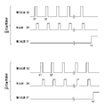
- FIG. 8 is a timing chart for explaining light distribution control.
- FIG. 9 is an example of a visible light distribution pattern obtained by controlling the first light source.
- FIG. 10 is a diagram illustrating a first method for ensuring the stability and accuracy of light distribution control.
- FIG. 11 is a diagram illustrating the first method.
- FIG. 12 is a timing chart illustrating the second method.
- FIG. 13 is a diagram showing another configuration of the HB unit.
- FIG. 2 is a horizontal cross-sectional view of the right headlight 10R shown in FIG.
- the right headlight 10R includes a rear body 12 having a recess that opens toward the front (in the straight-ahead (forward) direction of the vehicle 2).
- the rear body 12 forms a light chamber 16 by being combined with a transparent front cover 14 that covers the front opening thereof.
- a lamp unit hereinafter, referred to as “LB unit 20” that irradiates visible light having a predetermined wavelength (for example, visible light including a wavelength of 400 nm to 700 nm) as a low beam is provided. Have been placed.
- HB unit 30 a lamp unit that irradiates visible light having a predetermined wavelength (for example, visible light including a wavelength of 400 nm to 700 nm) as a high beam (hereinafter referred to as “HB unit 30”). Is placed.
- the LB unit 20 has a reflector 22 and a light source 24 supported by the reflector 22.
- the light source 24 is configured by using, for example, an LED (Light Emitting Diode), an incandescent bulb, or the like.
- the reflector 22 is supported in the light chamber 16 by using, for example, an aiming screw or a nut.
- the HB unit 30 realizes an ADB (Adaptive Driving Beam) that forms an optimum light distribution pattern in consideration of the presence of a vehicle in front and an oncoming vehicle.
- ADB Adaptive Driving Beam
- FIG. 3 shows the internal structure of the HB unit 30.
- the main part of the HB unit 30 is housed in the housing 30a.
- the housing 30a has a first lighting chamber 37 and a second lighting chamber 38 partitioned by a light-shielding wall 36.
- the first light room 37 is provided with a first light source 31, a second light source 32, and a rotary reflector 33, which form an irradiation system.
- the second lighting chamber 38 is provided with a light receiving unit 34 constituting a light receiving system.
- a lens component 35 and an optical filter 40 are provided in front of the housing 30a.
- FIG. 5 is a perspective view of the rotary reflector 33 shown in FIG.
- the rotary reflector 33 rotates with the shaft R as a rotation shaft by a drive source such as a motor.
- the rotary reflector 33 includes a substantially cylindrical shaft portion 33a centered on the shaft R, and three blades 33b extending in the radial direction from the shaft portion 33a.
- Each of the three blades 33b has a twisted shape in which the angle with respect to the axis R gradually changes in the circumferential direction.
- the surface of the three blades 33b on the side where the common substrate 39 is provided is a reflective surface that reflects visible light emitted from the first light source 31 and infrared light emitted from the second light source 32. A portion that reflects the light emitted from the first light source 31 toward the front and a portion that reflects the light of the second light source 32 toward the front are formed.
- the rotary reflector 33 reflects the light emitted from the first light source 31 and the second light source 32 while rotating, and forms a desired light distribution pattern in front of the vehicle 2.
- the rotary reflector 33 rotates, the light reflection direction changes from one end of the left and right end portions to the other end portion of the region in front of the vehicle 2 where the light distribution pattern is formed.
- the rotary reflector 33 illustrated is configured to rotate 120 degrees so that the light emitted from each of the first light source 31 and the second light source 32 can scan the front of the vehicle 2 once in one direction (horizontal direction). ing.
- the arrangement form of the first light source 31 and the second light source 32, the number and shape of the blades 33b, and the rotation speed of the rotation reflector 33 take into consideration, for example, the required mode and characteristics of the light distribution pattern, prevention of image flicker, and the like. Then, it is set based on the results of experiments and simulations.
- a suitable motor is one that can acquire information on rotation timing from the motor itself.
- the motor for example, a DC brushless motor is used.
- the light receiving unit 34 is a light receiving element (infrared sensor) capable of detecting the intensity of the reflected light emitted from the second light source 32 after being reflected by an object such as a vehicle in front or an oncoming vehicle. Is constructed using. When the light receiving unit 34 receives the reflected light, the light receiving unit 34 outputs a signal indicating the intensity of the received reflected light.
- the light receiving element is configured by using, for example, a semiconductor element such as a photodiode.
- FIG. 7 is a diagram illustrating an irradiation range of visible light and infrared light emitted from the vehicle lamp 1 of the present embodiment.
- the irradiation range of the light emitted from the vehicle lamp 1 is virtually installed vertically in front of the vehicle lamp 1 mounted on the vehicle 2 traveling on the road by a predetermined distance (for example, 25 m). It is shown as when projected on the screen.
- the range P1 is a low beam light distribution pattern irradiated by the LB unit 20.
- the range P2 is a band-shaped region extending in the left-right direction, and is an irradiation range of visible light emitted by the first light source 31 of the HB unit 30.
- the range P2 is, for example, a region similar to a general high beam light distribution pattern.
- the range P3 is an irradiation range of infrared light emitted by the second light source 32 of the HB unit 30.
- Range P2 includes range P21, range P22, and range P23.
- the range P21 is an irradiation range of visible light emitted from the first light source 31 provided at the uppermost position among the three first light sources 31 provided on the common substrate 39.
- the range P23 is an irradiation range of visible light emitted from the first light source 31 provided at the lowest level.
- the range P22 is an irradiation range of visible light emitted from the first light source 31 provided in the middle.
- the range P23 is set to be an area including a horizontal line (hereinafter, referred to as “H line”).
- Range P3 includes range P31, range P32, and range P33. All of these are linear regions extending in the left-right direction.
- the range P31 is the irradiation range of infrared light emitted from the second light source 32 provided at the highest position among the three second light sources 32 provided on the common substrate 39, and the range P33 is at the lowest level. It is an irradiation range of infrared light emitted from the second light source 32 provided, and the range P32 is an irradiation range of infrared light emitted from the second light source 32 provided in the middle.
- the range P31 is set to be located within the range P21.
- the range P32 is set to be located within the range P22.
- the range P33 is set to be located within the range P23.
- the linear region of the range P3 is set to have a vertical width of 0.4 degrees or more in the vertical direction, for example.
- the linear region of the range P33 is set so as to overlap the horizontal line viewed from the height at which the vehicle lamp 1 is mounted.
- FIG. 8 is a timing chart showing an example of light distribution control performed by the control unit 101.
- FIG. 8 shows the timing of turning on / off the first light source 31, the timing of turning on / off the second light source 32, and the timing of exposure of the light receiving unit 34.
- the control unit 101 turns on / off the second light source 32 at high speed while rotating the rotary reflector 33 so that the range P3 is sequentially irradiated with infrared light. Further, the control unit 101 exposes the light receiving unit 34 in synchronization with the lighting / extinguishing of the second light source 32.
- the point R1 in FIG. 7 is irradiated with infrared light.
- the other regions are not irradiated with infrared light, and neither is the visible light emitted from the first light source 31.
- the light receiving unit 34 is exposed, and the reflected light of the infrared light reflected at the point R1 is detected.
- the control unit 101 determines that there is an object at the point R1 and determines that the infrared light detected by the light receiving unit 34 has an object.
- the intensity of the reflected light is less than a predetermined value, it is determined that there is no object at the point R1.
- the rotation reflector 33 rotates by a predetermined angle from time t1, and when the second light source 32 is turned on, the point R2 in FIG. 7 is irradiated with infrared light. As in the case of the point R1, the other regions are not irradiated with infrared light and the visible light from the first light source 31 is not irradiated during this period. In this state, the light receiving unit 34 is exposed, and the reflected light of the infrared light reflected at the point R2 is detected.
- the control unit 101 determines that there is an object at the point R2, and determines that the infrared light detected by the light receiving unit 34 has an object.
- the intensity of the reflected light is less than a predetermined value, it is determined that there is no object at the point R2.
- control unit 101 By repeating turning on / off the second light source 32 while rotating the rotary reflector 33 in this way, the control unit 101 quickly (at least controls the light distribution) the presence / absence of an object at all points in the range P3. It can be determined (at the speed required to do it at a practical level).
- FIG. 9 is an example of a visible light distribution pattern obtained by controlling the first light source 31 by the control unit 101.
- the light distribution pattern is formed so as not to give glare to another vehicle (oncoming vehicle A) and to illuminate a wider range brightly, for example.
- the illustrated light distribution pattern is formed by the control unit 101 performing the following control.
- the area setting unit 103 of the control unit 101 sets the dimming area P4 at a position including the object (oncoming vehicle A) determined based on the result of the above determination.
- the control unit 101 supplies a current of the first current value to the first light source 31 by the light source control unit 102, and is usually directed toward a range excluding the dimming region P4 in the range P2 which is the irradiation range of the first light source 31.
- the control unit 101 supplies the first light source 31 with a current having a second current value smaller than the first current value by the light source control unit 102, and the illuminance is lower than the normal illuminance toward the dimming region P4. Irradiate visible light.
- the second light source 32 and the light receiving unit 34 which are sensing mechanisms, are provided close to the first light source 31.
- the parallax generated between the sensing mechanism and the first light source 31 can be reduced.
- the sensing mechanism can accurately determine the position of the actual object, the accuracy of the dimming region P4 set based on the determination result is improved.
- FIG. 10 is a diagram illustrating the first method, and is a graph showing the relationship between the relative intensity and wavelength of infrared light emitted from the second light source 32 of each of the left headlight 10L and the right headlight 10R.
- the second light source 32 of the left headlight 10L and the second light source of the right headlight 10R are infrared rays emitted from the second light source 32 of the left headlight 10L.
- the peak wavelength ⁇ 1 of the light and the peak wavelength ⁇ 2 of the infrared light emitted from the second light source 32 of the right headlight 10R are configured to be different.
- FIG. 11 is a graph showing the wavelength characteristic of the sensitivity of the light receiving portion 34 of the left headlight 10L and the wavelength characteristic of the sensitivity of the light receiving portion 34 of the right headlight 10R.
- the light receiving unit 34 of the left headlight 10L has a sensitivity of the infrared light emitted from the second light source 32 of the right headlight 10R to the peak wavelength ⁇ 2 of the left headlight 10L.
- the sensitivity of the infrared light emitted from the two light sources 32 to the peak wavelength ⁇ 1 is set to be smaller than the sensitivity.
- the wavelength is higher than a predetermined threshold.
- the light receiving unit 34 of the left headlight 10L is configured so as to exhibit high sensitivity but to exhibit sensitivity lower than a predetermined threshold for wavelengths outside the predetermined wavelength width.
- the sensitivity of the infrared light emitted from the second light source 32 of the left headlight 10L to the peak wavelength ⁇ 1 is emitted from the second light source 32 of the right headlight 10R.
- the light receiving unit 34 is irradiated with the incident light from either headlight. It is possible to determine whether it was a thing. It is possible to suppress the influence on the light distribution control due to the infrared light emitted from one of the second light sources 32 of the right side headlight 10R and the left side headlight 10L incident on the other light receiving unit 34. As a result, the independence of the right side headlight 10R and the left side headlight 10L is ensured, and the light distribution control in each can be performed stably and accurately. Further, according to the above method, infrared light can be emitted simultaneously from the second light source 32 of the right headlight 10R and the second light source 32 of the left headlight 10L, so that the arrangement with high time density is efficient. Light control can be performed.
- FIG. 12 is an example of the control performed in the vehicle lamp 1 with respect to the second method, and is a timing chart for explaining the control of the lighting timing of the first light source 31 and the second light source 32 and the exposure timing of the light receiving unit 34. be.
- the control in the second method will be described together with FIG. It is assumed that visible light is not emitted from the first light source 31 during the period during which the second light source 32 and the light receiving unit 34 are performing sensing.
- infrared light is emitted from the second light source 32 of the right headlight 10R, and the light receiving portion 34 of the right headlight 10R is exposed to be in a standby state for the reflected light of the infrared light.
- the exposure of the light receiving portion 34 of the right headlight 10R is stopped before the infrared light is emitted from the left headlight 10L. That is, the light receiving portion 34 of the right headlight 10R is prevented from being exposed during the period in which the reflected light of the light emitted from the second light source 32 of the left headlight 10L may be incident.
- infrared light is emitted from the second light source 32 of the left headlight 10L, and the light receiving portion 34 of the left headlight 10L is exposed, so that the reflected light of the infrared light is in a standby state. It becomes.
- the exposure of the light receiving portion 34 of the left headlight 10L is stopped before the infrared light is emitted from the second light source 32 of the right headlight 10R. That is, the light receiving portion 34 of the left headlight 10L is prevented from being exposed during the period in which the reflected light of the light emitted from the second light source 32 of the right headlight 10R may be incident.
- the control of the exposure timing of the light receiving unit 34 and the control of the lighting / extinguishing timing of the second light source 32 are repeated, so that the control unit 101 can perform all points within the range P3.
- the presence or absence of an object can be determined at high speed (at least at the speed required to control the light distribution at a practical level).
- the method of controlling the exposure of the light receiving unit 34 by the control unit 101 (the method of controlling whether or not the information output from the light receiving unit 34 is treated as valid) is not necessarily limited, but for example, the energization of the light receiving unit 34 is turned on and off. There are a method of determining the validity / invalidity of the information output from the light receiving unit 34, a method of determining the validity / invalidity of the information output from the light receiving unit 34 by an algorithm, and the like.
- the light reflected by the object reaches the light receiving unit 34 at the same time. There is nothing to do.
- the light receiving unit 34 of the right headlight 10R and the light receiving unit 34 of the left headlight 10L determine whether the light that arrived was the light emitted from the second light source 32 of the right headlight 10R or the left headlight 10L. Is less likely to be confused. Since the independence of the right headlight 10R and the left headlight 10L is ensured, the light emitted from the second light source 32 of either the right headlight 10R or the left headlight 10L is the light receiving portion 34 of the other.
- the light emitting elements used for the second light source 32 of the right headlight 10R and the second light source 32 of the left headlight 10L those having the same or similar peak wavelengths may be adopted. As a result, the number of parts can be reduced and the cost can be reduced.
- the light distribution control of the irradiation beam can be performed stably and accurately.
- the area for reducing the illuminance of the irradiation beam for preventing glare from being given to other vehicles (oncoming vehicles, etc.) is narrowed, which is normal.
- the area where the irradiation beam is irradiated can be widened by the illuminance, and the visibility during operation can be improved.
- the first light source 31 and the second light source 32 may be provided on independent substrates.
- three first light sources 31 are arranged linearly on the substrate 39a, and three second light sources 32 are arranged linearly on the substrate 39b.
- a third lens element 35c is further provided.
- the visible light emitted from the first light source 31 is transmitted through the second lens element 35b, and the infrared light emitted from the second light source 32 is transmitted through the third lens element 35c.
- a rotary reflector 33 is arranged.
- the sensitivity of the light receiving unit 34 to the light emitted from the first light source 31 may be set so as not to affect the light distribution control of the visible light emitted from the first light source 31.
- the sensitivity of the light receiving unit 34 is set, for example, by selecting a light receiving element constituting the light receiving unit 34 having characteristics corresponding to the sensitivity to be set. At this time, even when the visible light emitted from the first light source 31 is incident on the light receiving unit 34, the light receiving unit 34 does not detect the visible light due to the sensitivity setting of the light receiving unit 34. As a result, the influence of the first light source on the light distribution control can be reduced, so that the right headlight 10R and the left headlight 10L can perform the light distribution control more stably and accurately.
- the configuration of the vehicle lighting equipment 1 described above is irradiated toward a region where a near-infrared camera (near-infrared light (near-infrared)) is to be photographed, and the irradiated near-infrared light is reflected from an object. It may be applied to a camera that receives light and outputs an image or an image). Specifically, near-infrared light is emitted from the first light source 31, infrared light (infrared) is emitted from the second light source 32, and reflection is emitted from the second light source 32 and reflected by an object and returned.
- a near-infrared camera near-infrared light (near-infrared)
- near-infrared near-infrared light
- reflection is emitted from the second light source 32 and reflected by an object and returned.
- the light is received by the light receiving unit 34, and the light distribution pattern of the near infrared light emitted from the first light source 31 is controlled based on the intensity of the reflected light output by the light receiving unit 34.
- the above control is performed for the purpose of adjusting the brightness of the output video or image, for example. That is, for example, the clarity of the output image or image is improved by controlling the light distribution pattern so that the intensity of the near-infrared light irradiating the region where the intensity of the reflected light is small becomes high.
- the above control is performed for the purpose of reducing halation. That is, for example, halation is reduced by controlling the light distribution pattern so that the intensity of the near-infrared light irradiating the region where the intensity of the reflected light is high becomes small.
Abstract
This vehicle light is provided with a first lamp unit and a second lamp unit, each of which has: a first light source that emits an illumination beam (visible light); a second light source that emits infrared light which is for sensing and which has a peak wavelength differing from that of the first light source; and a light reception unit that detects the intensity of reflection light of the infrared light which has been emitted from the second light source. The light emitted from the first light source is subjected to light distribution control in accordance with the intensity of the reflection light which has been detected by the light reception unit, and the peak wavelength of the light emitted from the second light source of the first lamp unit differs from the peak wavelength of the light emitted from the second light source of the second lamp unit.
Description
本開示は、車両用灯具に関する。
This disclosure relates to vehicle lighting fixtures.
特許文献1には、可視光による配光を制御しつつ障害物の検出精度を向上することを目的として構成された障害物検出装置が記載されている。障害物検出装置は、車両用前照灯等として用いられ、可視光を出射するLEDユニットと、赤外光を出射する赤外光ユニットとを有する光源と、光源から出射した可視光及び赤外光を反射しながら回転軸を中心に一方向に回転する回転リフレクタと、赤外光のスペクトル領域に感度を有する撮像部とを備える。回転リフレクタは、回転動作により、LEDユニットからの可視光を照射ビームとして出射し、照射ビームを走査して第1の配光パターンを形成し、赤外光ユニットからの赤外光を照射ビームとして出射し、照射ビームを走査して第2の配光パターンを形成し、撮像部が取得した画像に基づき一部の領域に車両走行に障害のある障害物が存在するか判定し、一部の領域に障害物が存在している場合、障害物が可視光による照射ビームで照射されるように発光素子の点灯を制御する。
Patent Document 1 describes an obstacle detection device configured for the purpose of improving the detection accuracy of obstacles while controlling the light distribution by visible light. The obstacle detection device is used as a vehicle headlight or the like, and has a light source having an LED unit that emits visible light and an infrared light unit that emits infrared light, and visible light and infrared light emitted from the light source. It includes a rotary reflector that rotates in one direction about a rotation axis while reflecting light, and an imaging unit that has sensitivity in the spectral region of infrared light. The rotary reflector emits visible light from the LED unit as an irradiation beam by rotating, scans the irradiation beam to form a first light distribution pattern, and uses infrared light from the infrared light unit as an irradiation beam. It emits light, scans the irradiation beam to form a second light distribution pattern, determines whether there is an obstacle in a part of the area based on the image acquired by the imaging unit, and determines whether there is an obstacle in the vehicle running. When an obstacle exists in the area, the lighting of the light emitting element is controlled so that the obstacle is irradiated by the irradiation beam of visible light.
特許文献1に記載された障害物検出装置は、可視光とともに赤外光を出射し、赤外光のスペクトル領域に感度を有する撮像部により取得した画像に基づき一部の領域に車両走行に障害のある障害物が存在するか判定する。
The obstacle detection device described in Patent Document 1 emits infrared light together with visible light, and interferes with vehicle running in a part of the region based on an image acquired by an imaging unit having sensitivity in the spectrum region of infrared light. Determine if there is an obstacle with.
ここで特許文献1に開示されている障害物検出装置の構成を、例えば、車両の前端部左側に設けられる左側前照灯及び車両前端部右側に設けられる右側前照灯に夫々個別に適用し、各前照灯から出射する照射ビームの配光制御を個別に行おうとした場合、一方の前照灯から出射された赤外光が他方の前照灯の撮像部に入射することにより、配光制御の安定性や精度に影響が生じる可能性がある。
Here, the configuration of the obstacle detection device disclosed in Patent Document 1 is individually applied to, for example, the left headlight provided on the left side of the front end of the vehicle and the right headlight provided on the right side of the front end of the vehicle. , When the light distribution of the irradiation beam emitted from each headlight is controlled individually, the infrared light emitted from one headlight is incident on the imaging unit of the other headlight. The stability and accuracy of optical control may be affected.
本開示は、照射ビームの配光制御を安定して精度よく行うことが可能な車両用灯具を提供することを目的とする。
An object of the present disclosure is to provide a vehicle lamp capable of stably and accurately controlling the light distribution of an irradiation beam.
上記目的を達成するための本開示の一つは、車両用灯具であって、光を出射する第1光源と、前記第1光源とピーク波長の異なる光を出射する第2光源と、前記第2光源から出射した光の反射光の強度を検出する受光部と、をそれぞれ有する第1のランプユニットと第2のランプユニットと、前記受光部が検出した前記反射光の強度に応じて前記第1光源から出射する光を配光制御する制御部と、を備え、前記第1のランプユニットの前記第2光源から出射する光のピーク波長と、前記第2のランプユニットの前記第2光源から出射する光のピーク波長とが異なる。
One of the present disclosures for achieving the above object is a vehicle lighting tool, which comprises a first light source that emits light, a second light source that emits light having a peak wavelength different from that of the first light source, and the first light source. The first lamp unit and the second lamp unit having a light receiving unit for detecting the intensity of the reflected light of the light emitted from the two light sources, and the first lamp unit according to the intensity of the reflected light detected by the light receiving unit, respectively. A control unit for controlling the distribution of light emitted from one light source is provided, and the peak wavelength of light emitted from the second light source of the first lamp unit and the second light source of the second lamp unit are provided. The peak wavelength of the emitted light is different.
上記目的を達成するために本開示の一つは、車両用灯具であって、光を出射する第1光源と、前記第1光源とピーク波長の異なる光を出射する第2光源と、前記第2光源から出射した光の反射光の強度を検出する受光部と、をそれぞれ有する第1のランプユニットと第2のランプユニットと、前記受光部が検出した前記反射光の強度に応じて前記第1光源から出射する光を配光制御し、かつ、前記第1のランプユニットの前記第2光源と前記第2のランプユニットの前記第2光源とが同時に光を出射しないように制御する制御部を備える。
In order to achieve the above object, one of the present disclosure is a vehicle lighting tool, which comprises a first light source that emits light, a second light source that emits light having a peak wavelength different from that of the first light source, and the first light source. The first lamp unit and the second lamp unit having a light receiving unit for detecting the intensity of the reflected light of the light emitted from the two light sources, and the first lamp unit according to the intensity of the reflected light detected by the light receiving unit, respectively. A control unit that controls the light distribution emitted from one light source and controls so that the second light source of the first lamp unit and the second light source of the second lamp unit do not emit light at the same time. To be equipped with.
その他、本願が開示する課題、及びその解決方法は、発明を実施するための形態の欄、及び図面により明らかにされる。
In addition, the problems disclosed in the present application and the solutions thereof will be clarified by the column of the form for carrying out the invention and the drawings.
本開示によれば、照射ビームの配光制御を安定して精度よく行うことができる。
According to the present disclosure, the light distribution control of the irradiation beam can be performed stably and accurately.
以下、本開示を実施するための形態について図面を参照しつつ説明する。尚、以下の説明において、同一の又は類似する構成について共通の符号を付して重複した説明を省略することがある。
Hereinafter, the mode for carrying out the present disclosure will be described with reference to the drawings. In the following description, the same or similar configurations may be designated by a common reference numeral and duplicated description may be omitted.
図1は、一実施形態として示す車両用灯具1が搭載された車両2(自動車)の一例であり、車両2の前端部の様子を上方から眺めた図である。図1に示すように、車両2は、車両用灯具1として、車両2の前端部右側に搭載された右側前照灯10R、及び前端部左側に搭載された左側前照灯10Lを備える。尚、右側前照灯10R及び左側前照灯10Lは左右対称の構造となっている点以外は同様の構造を有するため、以下では主に右側前照灯10Rについて説明する。
FIG. 1 is an example of a vehicle 2 (automobile) equipped with a vehicle lamp 1 shown as an embodiment, and is a view of the front end portion of the vehicle 2 viewed from above. As shown in FIG. 1, the vehicle 2 includes a right headlight 10R mounted on the right side of the front end portion of the vehicle 2 and a left headlight 10L mounted on the left side of the front end portion as the vehicle lighting tool 1. Since the right side headlight 10R and the left side headlight 10L have the same structure except that they have a symmetrical structure, the right side headlight 10R will be mainly described below.
図2は、図1に示した右側前照灯10Rの水平断面図である。右側前照灯10Rは、前方(車両2の直進(前進)方向)に向かって開口する凹部を有する後方ボディ12を備える。後方ボディ12は、その前面開口を覆う透明な前方カバー14と組み合わされることにより灯室16を形成している。灯室16の左寄りには、所定波長の可視光(例えば、400nm~700nmの波長を含む可視光)をロービーム(Low Beam)として照射するランプユニット(以下、「LBユニット20」と称する。)が配置されている。また灯室16の右寄りには、所定波長の可視光(例えば、400nm~700nmの波長を含む可視光)をハイビーム(High Beam)として照射するランプユニット(以下、「HBユニット30」と称する。)が配置されている。
FIG. 2 is a horizontal cross-sectional view of the right headlight 10R shown in FIG. The right headlight 10R includes a rear body 12 having a recess that opens toward the front (in the straight-ahead (forward) direction of the vehicle 2). The rear body 12 forms a light chamber 16 by being combined with a transparent front cover 14 that covers the front opening thereof. To the left of the lamp chamber 16, a lamp unit (hereinafter, referred to as “LB unit 20”) that irradiates visible light having a predetermined wavelength (for example, visible light including a wavelength of 400 nm to 700 nm) as a low beam is provided. Have been placed. Further, on the right side of the lamp chamber 16, a lamp unit (hereinafter, referred to as “HB unit 30”) that irradiates visible light having a predetermined wavelength (for example, visible light including a wavelength of 400 nm to 700 nm) as a high beam (hereinafter referred to as “HB unit 30”). Is placed.
LBユニット20は、リフレクタ22と、当該リフレクタ22に支持された光源24とを有する。光源24は、例えば、LED(Light Emitting Diode)や白熱バルブ等を用いて構成される。リフレクタ22は、例えば、エイミングスクリューやナットを用いて灯室16内に支持される。HBユニット30は、前方車や対向車の存在を考慮した最適な配光パターンを形成するADB(Adaptive Driving Beam)を実現する。
The LB unit 20 has a reflector 22 and a light source 24 supported by the reflector 22. The light source 24 is configured by using, for example, an LED (Light Emitting Diode), an incandescent bulb, or the like. The reflector 22 is supported in the light chamber 16 by using, for example, an aiming screw or a nut. The HB unit 30 realizes an ADB (Adaptive Driving Beam) that forms an optimum light distribution pattern in consideration of the presence of a vehicle in front and an oncoming vehicle.
図3にHBユニット30の内部構造を示す。HBユニット30の要部はハウジング30aに収容されている。図3に示すように、ハウジング30aは、遮光壁36によって仕切られた第1灯室37と第2灯室38とを有する。第1灯室37には、照射系を構成する、第1光源31、第2光源32、及び回転リフレクタ33が設けられている。また第2灯室38には、受光系を構成する受光部34が、設けられている。ハウジング30aの前方には、レンズ部品35及び光学フィルタ40が設けられている。
FIG. 3 shows the internal structure of the HB unit 30. The main part of the HB unit 30 is housed in the housing 30a. As shown in FIG. 3, the housing 30a has a first lighting chamber 37 and a second lighting chamber 38 partitioned by a light-shielding wall 36. The first light room 37 is provided with a first light source 31, a second light source 32, and a rotary reflector 33, which form an irradiation system. Further, the second lighting chamber 38 is provided with a light receiving unit 34 constituting a light receiving system. A lens component 35 and an optical filter 40 are provided in front of the housing 30a.
第1光源31は、車両2の運転者が周囲を視認するために車両2の前方に照射される可視光(照射ビーム)を出射する。第1光源31は、例えば、LEDやLD(Laser Diode)等の発光素子を用いて構成される。第2光源32は、物体の検出等に用いられる赤外光(赤外線)を車両2の前方に出射する。第2光源32は、例えば、LD等の発光素子を用いて構成される。第1光源31及び第2光源32は、共通の基板(以下、「共通基板39」と称する。)の一方の面(回転リフレクタ33が存在する側の面)に設けられている。
The first light source 31 emits visible light (irradiation beam) emitted in front of the vehicle 2 so that the driver of the vehicle 2 can visually recognize the surroundings. The first light source 31 is configured by using, for example, a light emitting element such as an LED or an LD (Laser Diode). The second light source 32 emits infrared light (infrared rays) used for detecting an object or the like in front of the vehicle 2. The second light source 32 is configured by using, for example, a light emitting element such as an LD. The first light source 31 and the second light source 32 are provided on one surface (the surface on the side where the rotation reflector 33 exists) of a common substrate (hereinafter, referred to as "common substrate 39").
図4Aに、共通基板39を回転リフレクタ33が存在する側の面から眺めた平面図を示す。図4Aに示すように、共通基板39の表面には、3つの第1光源31が直線状に並設されている。また共通基板39には、3つの第1光源31に隣接して、3つの第2光源32が直線状に並設されている。
FIG. 4A shows a plan view of the common substrate 39 as viewed from the side where the rotating reflector 33 exists. As shown in FIG. 4A, three first light sources 31 are arranged side by side in a straight line on the surface of the common substrate 39. Further, on the common substrate 39, three second light sources 32 are arranged side by side in a straight line adjacent to the three first light sources 31.
第1光源31及び第2光源32の数や配列方法は必ずしも限定されない。例えば、図4Bに示すように、共通基板39に直線状に並設した3つの第2光源32の両側に、直線状に並設した3つの第1光源31を隣接して設けてもよい。この場合、第1光源31から出射される可視光(照射ビーム)の照射領域を広くすることができ、また照射領域をより明るく照らすことができる。
The number and arrangement method of the first light source 31 and the second light source 32 are not necessarily limited. For example, as shown in FIG. 4B, three linearly arranged first light sources 31 may be provided adjacent to each other on both sides of the three linearly arranged second light sources 32 on the common substrate 39. In this case, the irradiation area of the visible light (irradiation beam) emitted from the first light source 31 can be widened, and the irradiation area can be illuminated more brightly.
図5は、図3に示した回転リフレクタ33の斜視図である。回転リフレクタ33は、モータ等の駆動源によって軸Rを回転軸として回転する。回転リフレクタ33は、軸Rを中心軸とする略円柱状の軸部33a、及び軸部33aから径方向に延びる3つのブレード33bを備える。3つのブレード33bは、いずれも周方向に徐々に軸Rに対する角度が変化する捩れ形状になっている。3つのブレード33bの共通基板39が設けられている側の表面は、第1光源31から出射される可視光及び第2光源32から出射される赤外光を反射する反射面になっており、第1光源31から出射された光を前方に向けて反射する部分と、第2光源32の光を前方に向けて反射する部分とが形成されている。
FIG. 5 is a perspective view of the rotary reflector 33 shown in FIG. The rotary reflector 33 rotates with the shaft R as a rotation shaft by a drive source such as a motor. The rotary reflector 33 includes a substantially cylindrical shaft portion 33a centered on the shaft R, and three blades 33b extending in the radial direction from the shaft portion 33a. Each of the three blades 33b has a twisted shape in which the angle with respect to the axis R gradually changes in the circumferential direction. The surface of the three blades 33b on the side where the common substrate 39 is provided is a reflective surface that reflects visible light emitted from the first light source 31 and infrared light emitted from the second light source 32. A portion that reflects the light emitted from the first light source 31 toward the front and a portion that reflects the light of the second light source 32 toward the front are formed.
回転リフレクタ33は、回転しながら第1光源31及び第2光源32から出射した光を反射し、車両2の前方に所望の配光パターンを形成する。回転リフレクタ33が回転すると、光の反射方向は、配光パターンが形成される車両2前方の領域のうち、左右両端部の一方の端部から他方の端部に向かって変化する。例示する回転リフレクタ33は、120度回転することで、第1光源31及び第2光源32の夫々から出射する光によって車両2の前方を一方向(水平方向)に1回走査できるように構成されている。
The rotary reflector 33 reflects the light emitted from the first light source 31 and the second light source 32 while rotating, and forms a desired light distribution pattern in front of the vehicle 2. When the rotary reflector 33 rotates, the light reflection direction changes from one end of the left and right end portions to the other end portion of the region in front of the vehicle 2 where the light distribution pattern is formed. The rotary reflector 33 illustrated is configured to rotate 120 degrees so that the light emitted from each of the first light source 31 and the second light source 32 can scan the front of the vehicle 2 once in one direction (horizontal direction). ing.
第1光源31及び第2光源32の配置形態、ブレード33bの数や形状、及び回転リフレクタ33の回転速度は、例えば、必要とされる配光パターンの態様や特性、像のちらつき防止等を考慮して実験やシミュレーションの結果等に基づき設定される。モータは、モータ自身から回転タイミングに関する情報を取得できるものが適している。モータには、例えば、DCブラシレスモータが用いられる。
The arrangement form of the first light source 31 and the second light source 32, the number and shape of the blades 33b, and the rotation speed of the rotation reflector 33 take into consideration, for example, the required mode and characteristics of the light distribution pattern, prevention of image flicker, and the like. Then, it is set based on the results of experiments and simulations. A suitable motor is one that can acquire information on rotation timing from the motor itself. As the motor, for example, a DC brushless motor is used.
図3に戻り、受光部34は、第2光源32から出射する赤外光が前方車や対向車等の物体に反射されて戻ってくる反射光の強度を検出可能な受光素子(赤外線センサ)を用いて構成される。受光部34が反射光を受光すると、受光部34は受光した反射光の強さを示す信号を出力する。上記受光素子は、例えば、フォトダイオード等の半導体素子を用いて構成される。
Returning to FIG. 3, the light receiving unit 34 is a light receiving element (infrared sensor) capable of detecting the intensity of the reflected light emitted from the second light source 32 after being reflected by an object such as a vehicle in front or an oncoming vehicle. Is constructed using. When the light receiving unit 34 receives the reflected light, the light receiving unit 34 outputs a signal indicating the intensity of the received reflected light. The light receiving element is configured by using, for example, a semiconductor element such as a photodiode.
レンズ部品35は、第1灯室37の前方に配置される第1レンズ要素35aと、第2灯室38の前方に配置される第2レンズ要素35bとを含む。第1レンズ要素35aと第2レンズ要素35bは単一のレンズ部品として一体的に形成されている。第1レンズ要素35aの後方焦点F1の位置は、第2レンズ要素35bの後方焦点F2の位置よりも車両2の前方側にある。回転リフレクタ33は、その反射点が第1レンズ要素35aの焦点近傍に位置するように第1灯室37に設けられる。第1光源31及び第2光源32から出射して回転リフレクタ33で反射された光は、第1レンズ要素35aを通過して車両2の前方に向けて照射される。第2レンズ要素35bは、第2光源32から出射する赤外光が前方車や対向車等の物体に照射され、それにより車両2の前方から戻ってくる反射光を受光部34に集光する。受光部34は、その受光面が第2レンズ要素35bの焦点近傍に位置するように第2灯室38に設けられる。
The lens component 35 includes a first lens element 35a arranged in front of the first lighting chamber 37 and a second lens element 35b arranged in front of the second lighting chamber 38. The first lens element 35a and the second lens element 35b are integrally formed as a single lens component. The position of the rear focus F1 of the first lens element 35a is on the front side of the vehicle 2 with respect to the position of the rear focus F2 of the second lens element 35b. The rotary reflector 33 is provided in the first lamp chamber 37 so that its reflection point is located near the focal point of the first lens element 35a. The light emitted from the first light source 31 and the second light source 32 and reflected by the rotary reflector 33 passes through the first lens element 35a and is irradiated toward the front of the vehicle 2. The second lens element 35b irradiates an object such as a vehicle in front or an oncoming vehicle with infrared light emitted from the second light source 32, thereby condensing the reflected light returning from the front of the vehicle 2 on the light receiving unit 34. .. The light receiving unit 34 is provided in the second lighting chamber 38 so that the light receiving surface thereof is located near the focal point of the second lens element 35b.
遮光壁36は、第1レンズ要素35aの光軸と第2レンズ要素35bの光軸との間に設けられている。遮光壁36は、第1光源31や第2光源32から出射する光が受光部34に直接入射するのを遮るように設けられている。
The light-shielding wall 36 is provided between the optical axis of the first lens element 35a and the optical axis of the second lens element 35b. The light-shielding wall 36 is provided so as to block the light emitted from the first light source 31 and the second light source 32 from directly incident on the light receiving unit 34.
光学フィルタ40は、第2レンズ要素35bの裏面(受光部34と向かい合う面)に貼り付けられている。光学フィルタ40は、例えば、第1光源31から出射された可視光(またはその反射光)の減光、受光部34に入射する赤外線の波長選択等を行う。
The optical filter 40 is attached to the back surface (the surface facing the light receiving portion 34) of the second lens element 35b. The optical filter 40 performs, for example, dimming of visible light (or reflected light thereof) emitted from the first light source 31, wavelength selection of infrared rays incident on the light receiving unit 34, and the like.
図6は、車両用灯具1のシステムブロック図である。尚、左側前照灯10Lについては右側前照灯10Rと同様の構成を有するため、図6は簡略して描かれている。図6に示すように、右側前照灯10Rは、LBユニット20及びHBユニット30に加えて、制御部101を備える。制御部101は、第1光源31と第2光源32の点灯状態を制御する光源制御部102と、第1光源31から出射される可視光により他の領域よりも低い(可視光を照射しない場合も含む)照度で照射される減光領域を設定する領域設定部103と、及び通信ネットワークNを介して車両制御部3や左側前照灯10Lと通信する通信部104とを備える。制御部101は、例えば、電子制御ユニット(ECU)によって構成されていても良い。通信ネットワークNは、有線方式又は無線方式の通信基盤であり、例えば、CAN(Controller Area Network)等の通信プロトコルに準拠して構成された車内LAN(Local Area Network)である。制御部101は、LBユニット20と、第1光源31と、第2光源32と、及び回転リフレクタ33のモータ33cと、受光部34とを制御する。尚、制御部101は、左側前照灯10Lと右側前照灯10Rの片方のみに存在して、左側前照灯10Lと右側前照灯10Rの双方を制御しても良い。
FIG. 6 is a system block diagram of the vehicle lamp 1. Since the left headlight 10L has the same configuration as the right headlight 10R, FIG. 6 is simply drawn. As shown in FIG. 6, the right headlight 10R includes a control unit 101 in addition to the LB unit 20 and the HB unit 30. The control unit 101 is lower than the other regions by the light source control unit 102 that controls the lighting state of the first light source 31 and the second light source 32 and the visible light emitted from the first light source 31 (when the visible light is not irradiated). It also includes an area setting unit 103 that sets a dimming region to be irradiated with illuminance, and a communication unit 104 that communicates with the vehicle control unit 3 and the left headlight 10L via the communication network N. The control unit 101 may be composed of, for example, an electronic control unit (ECU). The communication network N is a wired or wireless communication infrastructure, and is, for example, an in-vehicle LAN (Local Area Network) configured in accordance with a communication protocol such as CAN (Controller Area Network). The control unit 101 controls the LB unit 20, the first light source 31, the second light source 32, the motor 33c of the rotary reflector 33, and the light receiving unit 34. The control unit 101 may exist in only one of the left side headlight 10L and the right side headlight 10R, and may control both the left side headlight 10L and the right side headlight 10R.
車両制御部3は、例えば、電子制御ユニット(ECU:Electronic Control Unit)を用いて構成されている。車両制御部3は、車両2に搭載されている各種の装置、例えば、車載カメラ6、各種センサ5(加速度センサ、速度センサ、ジャイロセンサ、GPS(Global Positioning System))、各種レーダ7(ミリ波レーダ、マイクロ波レーダ、レーザーレーダ、LiDAR(Light Detection and RangingまたはLaser Imaging Detection and Ranging)等)、HMI8(Human Machine Interface)、アクセル機構17、ブレーキ機構15、ステアリング機構13等と通信し、これらの装置から取得される情報を通信ネットワークNを介して制御部101に送信する。尚、車載カメラ6及び各種レーダ7は、例えば、車両2の周辺環境(他車、歩行者、道路形状、交通標識、障害物等)に関する情報を車両制御部3に入力する。光源制御部102は、受信した制御信号に基づき、LBユニット20と、第1光源31と、第2光源32と、及び回転リフレクタ33のモータ33cとを制御する。
The vehicle control unit 3 is configured by using, for example, an electronic control unit (ECU: Electronic Control Unit). The vehicle control unit 3 includes various devices mounted on the vehicle 2, for example, an in-vehicle camera 6, various sensors 5 (acceleration sensor, speed sensor, gyro sensor, GPS (Global Positioning System)), and various radars 7 (millimeter waves). It communicates with radar, microwave radar, laser radar, LiDAR (Light Detection and Ringing or Laser Imaging Detection and Ringing), HMI8 (Human Machine Interface), accelerator mechanism 17, brake mechanism 15, steering mechanism 13, etc. The information acquired from the device is transmitted to the control unit 101 via the communication network N. The in-vehicle camera 6 and various radars 7 input information on the surrounding environment of the vehicle 2 (other vehicles, pedestrians, road shapes, traffic signs, obstacles, etc.) to the vehicle control unit 3, for example. The light source control unit 102 controls the LB unit 20, the first light source 31, the second light source 32, and the motor 33c of the rotary reflector 33 based on the received control signal.
図7は、本実施形態の車両用灯具1から出射される可視光及び赤外光の照射範囲を説明する図である。図7では、車両用灯具1から出射される光の照射範囲を、道路を走行中の車両2に搭載された車両用灯具1から所定距離(例えば25m)前方に鉛直に仮想的に設置した仮想スクリーンに投影した場合として表している。
FIG. 7 is a diagram illustrating an irradiation range of visible light and infrared light emitted from the vehicle lamp 1 of the present embodiment. In FIG. 7, the irradiation range of the light emitted from the vehicle lamp 1 is virtually installed vertically in front of the vehicle lamp 1 mounted on the vehicle 2 traveling on the road by a predetermined distance (for example, 25 m). It is shown as when projected on the screen.
図7において、範囲P1は、LBユニット20が照射するロービームの配光パターンである。範囲P2は、左右方向に延びる帯状の領域であり、HBユニット30の第1光源31が出射する可視光の照射範囲である。範囲P2は、例えば、一般的なハイビームの配光パターンと同様の領域である。範囲P3は、HBユニット30の第2光源32が出射する赤外光の照射範囲である。
In FIG. 7, the range P1 is a low beam light distribution pattern irradiated by the LB unit 20. The range P2 is a band-shaped region extending in the left-right direction, and is an irradiation range of visible light emitted by the first light source 31 of the HB unit 30. The range P2 is, for example, a region similar to a general high beam light distribution pattern. The range P3 is an irradiation range of infrared light emitted by the second light source 32 of the HB unit 30.
範囲P2は、範囲P21、範囲P22、及び範囲P23を含む。範囲P21は、共通基板39に設けられた3つの第1光源31のうち、最上位に設けられた第1光源31から出射される可視光の照射範囲である。範囲P23は、最下位に設けられた第1光源31から出射される可視光の照射範囲である。範囲P22は、中間に設けられた第1光源31から出射される可視光の照射範囲である。範囲P23は、水平線(以下、「H線」と称する。)を含む領域になるように設定される。
Range P2 includes range P21, range P22, and range P23. The range P21 is an irradiation range of visible light emitted from the first light source 31 provided at the uppermost position among the three first light sources 31 provided on the common substrate 39. The range P23 is an irradiation range of visible light emitted from the first light source 31 provided at the lowest level. The range P22 is an irradiation range of visible light emitted from the first light source 31 provided in the middle. The range P23 is set to be an area including a horizontal line (hereinafter, referred to as “H line”).
範囲P3は、範囲P31、範囲P32、及び範囲P33を含む。これらはいずれも左右方向に延びる直線状の領域である。範囲P31は、共通基板39に設けられた3つの第2光源32のうち、最上位に設けられた第2光源32から出射される赤外光の照射範囲であり、範囲P33は、最下位に設けられた第2光源32から出射される赤外光の照射範囲であり、範囲P32は、中間に設けられた第2光源32から出射される赤外光の照射範囲である。範囲P31は範囲P21の中に位置するように設定される。範囲P32は範囲P22の中に位置するように設定される。範囲P33は範囲P23の中に位置するように設定される。範囲P3の直線状領域は、例えば、鉛直方向に0.4度以上の上下幅を有するように設定される。本例では、範囲P33の直線状領域は、車両用灯具1が搭載されている高さから眺めた水平線と重なるように設定されている。
Range P3 includes range P31, range P32, and range P33. All of these are linear regions extending in the left-right direction. The range P31 is the irradiation range of infrared light emitted from the second light source 32 provided at the highest position among the three second light sources 32 provided on the common substrate 39, and the range P33 is at the lowest level. It is an irradiation range of infrared light emitted from the second light source 32 provided, and the range P32 is an irradiation range of infrared light emitted from the second light source 32 provided in the middle. The range P31 is set to be located within the range P21. The range P32 is set to be located within the range P22. The range P33 is set to be located within the range P23. The linear region of the range P3 is set to have a vertical width of 0.4 degrees or more in the vertical direction, for example. In this example, the linear region of the range P33 is set so as to overlap the horizontal line viewed from the height at which the vehicle lamp 1 is mounted.
図8は、制御部101が行う配光制御の一例を表すタイミングチャートである。図8には、第1光源31の点灯/消灯のタイミング、第2光源32の点灯/消灯のタイミング、及び受光部34の露光のタイミングが示されている。図8に示すように、制御部101は、範囲P3に赤外光が順次照射されるように回転リフレクタ33を回転させつつ、第2光源32を高速で点灯/消灯させる。また制御部101は、この第2光源32の点灯/消灯に同期させて受光部34を露光させる。尚、第1光源31から出射した可視光が受光部34に入射することによる配光制御への影響を防ぐため、本例では、制御部101は、第2光源32が点灯する可能性のある期間中(センシング動作中)は第1光源31を消灯させている。
FIG. 8 is a timing chart showing an example of light distribution control performed by the control unit 101. FIG. 8 shows the timing of turning on / off the first light source 31, the timing of turning on / off the second light source 32, and the timing of exposure of the light receiving unit 34. As shown in FIG. 8, the control unit 101 turns on / off the second light source 32 at high speed while rotating the rotary reflector 33 so that the range P3 is sequentially irradiated with infrared light. Further, the control unit 101 exposes the light receiving unit 34 in synchronization with the lighting / extinguishing of the second light source 32. In addition, in order to prevent the influence of the visible light emitted from the first light source 31 on the light distribution control due to the incident on the light receiving unit 34, in this example, the control unit 101 may turn on the second light source 32. During the period (during the sensing operation), the first light source 31 is turned off.
図8における時刻t1では、図7の点R1に赤外光が照射される。この間、他の領域には赤外光が照射されず、また第1光源31から可視光も照射されない。この状態で受光部34が露光し、点R1で反射された赤外光の反射光が検出される。そして制御部101は、例えば、受光部34で検出された赤外光の反射光の強度が所定値以上である場合は点R1に物体があると判定し、受光部34で検出された赤外線の反射光の強度が所定値未満である場合は点R1に物体がないと判定する。
At time t1 in FIG. 8, the point R1 in FIG. 7 is irradiated with infrared light. During this period, the other regions are not irradiated with infrared light, and neither is the visible light emitted from the first light source 31. In this state, the light receiving unit 34 is exposed, and the reflected light of the infrared light reflected at the point R1 is detected. Then, for example, when the intensity of the reflected light of the infrared light detected by the light receiving unit 34 is equal to or higher than a predetermined value, the control unit 101 determines that there is an object at the point R1 and determines that the infrared light detected by the light receiving unit 34 has an object. When the intensity of the reflected light is less than a predetermined value, it is determined that there is no object at the point R1.
時刻t2では、時刻t1から回転リフレクタ33は所定角度回転し、第2光源32が点灯すると図7の点R2に赤外光が照射される。上記点R1の場合と同様、この間、他の領域には赤外光が照射されず、第1光源31からの可視光も照射されていない。この状態で受光部34が露光し、点R2で反射された赤外光の反射光が検出される。そして制御部101は、例えば、受光部34で検出された赤外光の反射光の強度が所定値以上である場合は点R2に物体があると判定し、受光部34で検出された赤外線の反射光の強度が所定値未満である場合は点R2に物体がないと判定する。
At time t2, the rotation reflector 33 rotates by a predetermined angle from time t1, and when the second light source 32 is turned on, the point R2 in FIG. 7 is irradiated with infrared light. As in the case of the point R1, the other regions are not irradiated with infrared light and the visible light from the first light source 31 is not irradiated during this period. In this state, the light receiving unit 34 is exposed, and the reflected light of the infrared light reflected at the point R2 is detected. Then, for example, when the intensity of the reflected light of the infrared light detected by the light receiving unit 34 is equal to or higher than a predetermined value, the control unit 101 determines that there is an object at the point R2, and determines that the infrared light detected by the light receiving unit 34 has an object. When the intensity of the reflected light is less than a predetermined value, it is determined that there is no object at the point R2.
このようにして回転リフレクタ33を回転させつつ第2光源32の点灯/消灯が繰り返されることで、制御部101は、範囲P3内の全ての点について物体の有無を高速に(少なくとも配光制御を実用的なレベルで行うために必要な速度で)判定することができる。
By repeating turning on / off the second light source 32 while rotating the rotary reflector 33 in this way, the control unit 101 quickly (at least controls the light distribution) the presence / absence of an object at all points in the range P3. It can be determined (at the speed required to do it at a practical level).
範囲P3内の全ての点に向けて第2光源32から赤外光を照射すると、制御部101は、受光部34の出力に基づき物体の有無を判定し、判定した結果に基づき第1光源31の制御(点灯、消灯、減光)を行う。尚、上記判定は、車両制御部3から提供される前述した情報(車載カメラ6や各種レーダ7の情報等)を更に加味して行うようにしてもよい。
When infrared light is irradiated from the second light source 32 toward all points in the range P3, the control unit 101 determines the presence or absence of an object based on the output of the light receiving unit 34, and the first light source 31 is based on the determination result. Control (lighting, turning off, dimming). The above determination may be made by further adding the above-mentioned information (information of the vehicle-mounted camera 6 and various radars 7 and the like) provided by the vehicle control unit 3.
図9は、制御部101が第1光源31を制御することにより得られる可視光の配光パターンの一例である。配光パターンは、例えば、他車両(対向車A)へグレアを与えず、かつ、より広い範囲を明るく照らすように形成される。例示する配光パターンは、制御部101が次の制御を行うことにより形成される。制御部101の領域設定部103は、上記判定の結果に基づき判別された物体(対向車A)を含む位置に減光領域P4を設定する。制御部101は、光源制御部102により、第1光源31に第1電流値の電流を供給し、第1光源31の照射範囲である範囲P2における減光領域P4を除いた範囲に向けて通常の照度で可視光を照射する。そして、制御部101は、光源制御部102により、第1光源31に第1電流値より小さい第2電流値の電流を供給し、減光領域P4に向けて上記通常の照度よりも低い照度で可視光を照射する。
FIG. 9 is an example of a visible light distribution pattern obtained by controlling the first light source 31 by the control unit 101. The light distribution pattern is formed so as not to give glare to another vehicle (oncoming vehicle A) and to illuminate a wider range brightly, for example. The illustrated light distribution pattern is formed by the control unit 101 performing the following control. The area setting unit 103 of the control unit 101 sets the dimming area P4 at a position including the object (oncoming vehicle A) determined based on the result of the above determination. The control unit 101 supplies a current of the first current value to the first light source 31 by the light source control unit 102, and is usually directed toward a range excluding the dimming region P4 in the range P2 which is the irradiation range of the first light source 31. Irradiate visible light with the illuminance of. Then, the control unit 101 supplies the first light source 31 with a current having a second current value smaller than the first current value by the light source control unit 102, and the illuminance is lower than the normal illuminance toward the dimming region P4. Irradiate visible light.
以上に説明したように、本実施形態の車両用灯具1によれば、第1光源31から出射する光を走査して配光パターンを形成するとともに、第1光源31の発光強度を制御することで配光パターンの一部に任意に照度の低い領域を形成することができる。また右側前照灯10Rと左側前照灯10Lは夫々、車両前方をセンシングするためのセンシング機構として、第2光源32と受光部34を備える。第2光源は赤外線を照射するので、夜間など視認が容易でないときであっても、正確に前方を走査できる。前方を走査した結果に応じて、第1光源の配光パターンの一部領域に、第1光源から出射する可視光が照射することができる。
As described above, according to the vehicle lamp 1 of the present embodiment, the light emitted from the first light source 31 is scanned to form a light distribution pattern, and the emission intensity of the first light source 31 is controlled. It is possible to arbitrarily form a region with low illuminance in a part of the light distribution pattern. Further, the right headlight 10R and the left headlight 10L each include a second light source 32 and a light receiving unit 34 as sensing mechanisms for sensing the front of the vehicle. Since the second light source irradiates infrared rays, it is possible to accurately scan the front even when it is not easy to see, such as at night. Visible light emitted from the first light source can irradiate a part of the light distribution pattern of the first light source according to the result of scanning the front.
ところで、車載カメラ6などのセンシング機構が第1光源から離れた位置に設けられた場合、センシング機構と第1光源31との間に視差が発生する。このとき、センシング機構が実際の物体の位置を正確に判別できず、判別結果に基づき設定された減光領域P4の位置も正確に設定できない虞がある。
By the way, when a sensing mechanism such as an in-vehicle camera 6 is provided at a position away from the first light source, parallax occurs between the sensing mechanism and the first light source 31. At this time, the sensing mechanism may not be able to accurately determine the actual position of the object, and the position of the dimming region P4 set based on the determination result may not be accurately set.
本実施形態の車両用灯具1では、センシング機構である第2光源32及び受光部34は、第1光源31に近接して設けられている。これにより、センシング機構と第1光源31との間に発生する視差を低減することができる。このとき、センシング機構は実際の物体の位置を正確に判別できるため、判別結果に基づいて設定される減光領域P4の精度が向上する。
In the vehicle lamp 1 of the present embodiment, the second light source 32 and the light receiving unit 34, which are sensing mechanisms, are provided close to the first light source 31. As a result, the parallax generated between the sensing mechanism and the first light source 31 can be reduced. At this time, since the sensing mechanism can accurately determine the position of the actual object, the accuracy of the dimming region P4 set based on the determination result is improved.
ところで、配光パターンの制御を安定して精度よく行うためには、右側前照灯10Rと左側前照灯10Lの独立性を確保する必要がある。例えば、右側前照灯10Rの第2光源32から出射した赤外光が左側前照灯10Lの受光部34に入射することで、左側前照灯10Lの第1光源31による配光パターンの制御に影響が生じる可能性がある。また逆に、左側前照灯10Lの第2光源32から出射した赤外光が右側前照灯10Rの受光部34に入射することで、左側前照灯10Lの第1光源31による配光パターンの制御に影響が生じる可能性がある。そこで以下では、この問題についてのいくつかの解決方法について説明する。
By the way, in order to control the light distribution pattern stably and accurately, it is necessary to secure the independence of the right headlight 10R and the left headlight 10L. For example, the infrared light emitted from the second light source 32 of the right headlight 10R is incident on the light receiving portion 34 of the left headlight 10L, so that the light distribution pattern is controlled by the first light source 31 of the left headlight 10L. May be affected. On the contrary, the infrared light emitted from the second light source 32 of the left headlight 10L is incident on the light receiving portion 34 of the right headlight 10R, so that the light distribution pattern by the first light source 31 of the left headlight 10L May affect the control of. Therefore, some solutions to this problem will be described below.
図10は、第1の方法を説明する図であり、左側前照灯10L及び右側前照灯10Rの夫々の第2光源32から出射する赤外光の相対強度と波長との関係を示すグラフである。図10に示すように、第1の方法では、左側前照灯10Lの第2光源32と右側前照灯10Rの第2光源は、左側前照灯10Lの第2光源32から出射する赤外光のピーク波長λ1と、右側前照灯10Rの第2光源32から出射する赤外光のピーク波長λ2とが異なるように構成される。具体的には、例えば、左側前照灯10Lの第2光源32と右側前照灯10Rの第2光源を構成する発光素子に、ピーク波長が異なるものを採用してもよい。また左側前照灯10Lの第2光源32と右側前照灯10Rの第2光源32とが複数のピーク波長を設定可能に構成されることによって、左側前照灯10Lの第2光源32と右側前照灯10Rの第2光源32とが、互いに異なる波長の赤外光を出射するように構成されてもよい。
FIG. 10 is a diagram illustrating the first method, and is a graph showing the relationship between the relative intensity and wavelength of infrared light emitted from the second light source 32 of each of the left headlight 10L and the right headlight 10R. Is. As shown in FIG. 10, in the first method, the second light source 32 of the left headlight 10L and the second light source of the right headlight 10R are infrared rays emitted from the second light source 32 of the left headlight 10L. The peak wavelength λ 1 of the light and the peak wavelength λ 2 of the infrared light emitted from the second light source 32 of the right headlight 10R are configured to be different. Specifically, for example, the light emitting elements constituting the second light source 32 of the left headlight 10L and the second light source of the right headlight 10R may have different peak wavelengths. Further, the second light source 32 of the left headlight 10L and the second light source 32 of the right headlight 10R are configured so that a plurality of peak wavelengths can be set, so that the second light source 32 of the left headlight 10L and the right side can be set. The second light source 32 of the headlight 10R may be configured to emit infrared light having different wavelengths from each other.
また第1の方法では、右側前照灯10Rの第2光源32から出射した赤外光(の反射光)が左側前照灯10Lの第1光源31から出射した可視光の配光制御に影響を与えないように、左側前照灯10Lの受光部34の感度は設定される。また、左側前照灯10Lの第2光源32から出射した赤外光(の反射光が、右側前照灯10Rの第1光源31から出射した可視光の配光制御に影響を与えないように、右側前照灯10Rの受光部34の感度は設定される。
Further, in the first method, the infrared light (reflected light) emitted from the second light source 32 of the right headlight 10R affects the light distribution control of the visible light emitted from the first light source 31 of the left headlight 10L. The sensitivity of the light receiving unit 34 of the left headlight 10L is set so as not to give the above. Further, the infrared light (reflected light) emitted from the second light source 32 of the left headlight 10L does not affect the light distribution control of the visible light emitted from the first light source 31 of the right headlight 10R. , The sensitivity of the light receiving unit 34 of the right headlight 10R is set.
図11は、左側前照灯10Lの受光部34の感度の波長特性、及び右側前照灯10Rの受光部34の感度の波長特性を示すグラフである。図11に示すように、左側前照灯10Lの受光部34は、右側前照灯10Rの第2光源32から出射した赤外光のピーク波長λ2に対する感度が、左側前照灯10Lの第2光源32から出射した赤外光のピーク波長λ1に対する感度よりも小さくなるように設定される。例えば、左側前照灯10Lの第2光源32から出射した赤外光のピーク波長λ1を中心とする所定波長幅(波長λ2を含まない)内の波長に対しては所定の閾値よりも高い感度を示すが、上記所定波長幅外の波長に対しては所定の閾値よりも低い感度を示すように、左側前照灯10Lの受光部34は構成される。また右側前照灯10Rの受光部34は、左側前照灯10Lの第2光源32から出射した赤外光のピーク波長λ1に対する感度が、右側前照灯10Rの第2光源32から出射した赤外光のピーク波長λ2に対する感度よりも小さくなるように設定する。例えば、右側前照灯10Rの第2光源32から出射した赤外光のピーク波長λ2を中心とする所定波長幅(波長λ1を含まない)内の波長に対しては所定の閾値よりも高い感度を示すが、上記所定波長幅外の波長に対しては所定の閾値よりも低い感度を示すように、右側前照灯10Rの受光部34は構成される。尚、受光部34の感度の設定は、例えば、所望の感度を得られる受光素子を受光部34が備えることで実現できる。また左側前照灯10Lの受光部34及び右側前照灯10Rの受光部34は、感度が最大となる波長を設定可能に構成されることで、左側前照灯10Lの受光部34と右側前照灯10Rの受光部34とが互いに異なる波長で最大感度を示すように構成されてもよい。
FIG. 11 is a graph showing the wavelength characteristic of the sensitivity of the light receiving portion 34 of the left headlight 10L and the wavelength characteristic of the sensitivity of the light receiving portion 34 of the right headlight 10R. As shown in FIG. 11, the light receiving unit 34 of the left headlight 10L has a sensitivity of the infrared light emitted from the second light source 32 of the right headlight 10R to the peak wavelength λ 2 of the left headlight 10L. The sensitivity of the infrared light emitted from the two light sources 32 to the peak wavelength λ 1 is set to be smaller than the sensitivity. For example, for wavelengths within a predetermined wavelength width ( excluding wavelength λ 2 ) centered on the peak wavelength λ 1 of infrared light emitted from the second light source 32 of the left headlight 10L, the wavelength is higher than a predetermined threshold. The light receiving unit 34 of the left headlight 10L is configured so as to exhibit high sensitivity but to exhibit sensitivity lower than a predetermined threshold for wavelengths outside the predetermined wavelength width. Further, in the light receiving unit 34 of the right headlight 10R, the sensitivity of the infrared light emitted from the second light source 32 of the left headlight 10L to the peak wavelength λ 1 is emitted from the second light source 32 of the right headlight 10R. It is set to be smaller than the sensitivity of infrared light to the peak wavelength λ 2. For example, for wavelengths within a predetermined wavelength width ( excluding wavelength λ 1 ) centered on the peak wavelength λ 2 of infrared light emitted from the second light source 32 of the right headlight 10R, the wavelength is higher than the predetermined threshold. The light receiving unit 34 of the right headlight 10R is configured so as to exhibit high sensitivity but to exhibit sensitivity lower than a predetermined threshold for wavelengths outside the predetermined wavelength width. The sensitivity of the light receiving unit 34 can be set, for example, by providing the light receiving element 34 with a light receiving element capable of obtaining a desired sensitivity. Further, the light receiving portion 34 of the left headlight 10L and the light receiving portion 34 of the right headlight 10R are configured so that the wavelength that maximizes the sensitivity can be set, so that the light receiving portion 34 of the left headlight 10L and the right front The light receiving portion 34 of the headlight 10R may be configured to exhibit maximum sensitivity at wavelengths different from each other.
第1の方法によれば、右側前照灯10R及び左側前照灯10Lの第2光源のピーク波長は互いに異なっているので、受光部34は入射した光がどちらの前照灯から照射されたものであったかを判別することができる。右側前照灯10R及び左側前照灯10Lのうちの一方の第2光源32から出射した赤外光が他方の受光部34に入射することによる配光制御への影響を抑えることができる。これにより右側前照灯10Rと左側前照灯10Lの独立性が確保され、夫々における配光制御を安定して精度よく行うことができる。また以上の方法によれば、右側前照灯10Rの第2光源32と左側前照灯10Lの第2光源32とから同時に赤外光を出射することができるので、効率よく時間密度の高い配光制御を行うことができる。
According to the first method, since the peak wavelengths of the second light sources of the right headlight 10R and the left headlight 10L are different from each other, the light receiving unit 34 is irradiated with the incident light from either headlight. It is possible to determine whether it was a thing. It is possible to suppress the influence on the light distribution control due to the infrared light emitted from one of the second light sources 32 of the right side headlight 10R and the left side headlight 10L incident on the other light receiving unit 34. As a result, the independence of the right side headlight 10R and the left side headlight 10L is ensured, and the light distribution control in each can be performed stably and accurately. Further, according to the above method, infrared light can be emitted simultaneously from the second light source 32 of the right headlight 10R and the second light source 32 of the left headlight 10L, so that the arrangement with high time density is efficient. Light control can be performed.
第2の方法では、右側前照灯10Rの第2光源32と左側前照灯10Lの第2光源32とが同時に赤外光を出射しないように、右側前照灯10R及び左側前照灯10Lの夫々の制御部101が、夫々の第2光源32の点灯/消灯のタイミングを制御するようにする。具体的には、右側前照灯10Rの制御部と左側前照灯10Lの制御部101とが通信ネットワークNを介して通信することにより、右側前照灯10Rの第2光源32と左側前照灯10Lの第2光源32とが同時に赤外光を出射しないように、双方の第2光源の点灯/消灯のタイミングを制御するようにする。
In the second method, the right headlight 10R and the left headlight 10L are used so that the second light source 32 of the right headlight 10R and the second light source 32 of the left headlight 10L do not emit infrared light at the same time. Each control unit 101 controls the timing of turning on / off the second light source 32. Specifically, the control unit of the right headlight 10R and the control unit 101 of the left headlight 10L communicate with each other via the communication network N, whereby the second light source 32 of the right headlight 10R and the left headlight The timing of turning on / off both of the second light sources is controlled so that the second light source 32 of the lamp 10L does not emit infrared light at the same time.
図12は、第2の方法に関して車両用灯具1において行われる制御の一例であり、第1光源31と第2光源32の点灯タイミング、及び受光部34の露光タイミングの制御を説明するタイミングチャートである。以下、図12とともに第2の方法における制御について説明する。尚、第2光源32と受光部34によるセンシングが行われている期間中、第1光源31から可視光は出射されないものとする。
FIG. 12 is an example of the control performed in the vehicle lamp 1 with respect to the second method, and is a timing chart for explaining the control of the lighting timing of the first light source 31 and the second light source 32 and the exposure timing of the light receiving unit 34. be. Hereinafter, the control in the second method will be described together with FIG. It is assumed that visible light is not emitted from the first light source 31 during the period during which the second light source 32 and the light receiving unit 34 are performing sensing.
まず時刻t1において、右側前照灯10Rの第2光源32から赤外光が出射するとともに右側前照灯10Rの受光部34が露光されて上記赤外光の反射光の待機状態となる。その後、左側前照灯10Lから赤外光が出射する前に右側前照灯10Rの受光部34の露光が停止される。即ち、左側前照灯10Lの第2光源32から出射した光の反射光が入射する可能性のある期間に右側前照灯10Rの受光部34が露光されないようにする。
First, at time t1, infrared light is emitted from the second light source 32 of the right headlight 10R, and the light receiving portion 34 of the right headlight 10R is exposed to be in a standby state for the reflected light of the infrared light. After that, the exposure of the light receiving portion 34 of the right headlight 10R is stopped before the infrared light is emitted from the left headlight 10L. That is, the light receiving portion 34 of the right headlight 10R is prevented from being exposed during the period in which the reflected light of the light emitted from the second light source 32 of the left headlight 10L may be incident.
続いて、時刻t1’において、左側前照灯10Lの第2光源32から赤外光が出射するとともに左側前照灯10Lの受光部34が露光されて、上記赤外光の反射光の待機状態となる。その後、右側前照灯10Rの第2光源32から赤外光が出射する前に左側前照灯10Lの受光部34の露光が停止される。即ち、右側前照灯10Rの第2光源32から出射した光の反射光が入射する可能性のある期間に左側前照灯10Lの受光部34が露光されないようにする。
Subsequently, at time t1', infrared light is emitted from the second light source 32 of the left headlight 10L, and the light receiving portion 34 of the left headlight 10L is exposed, so that the reflected light of the infrared light is in a standby state. It becomes. After that, the exposure of the light receiving portion 34 of the left headlight 10L is stopped before the infrared light is emitted from the second light source 32 of the right headlight 10R. That is, the light receiving portion 34 of the left headlight 10L is prevented from being exposed during the period in which the reflected light of the light emitted from the second light source 32 of the right headlight 10R may be incident.
時刻t2においては、時刻t1で行われた制御と同様の制御が行われる。続いて、時刻t2’においては、時刻t1’で行われた制御と同様の制御が行われる。
At time t2, the same control as that performed at time t1 is performed. Subsequently, at time t2', the same control as that performed at time t1'is performed.
このようにして回転リフレクタ33を回転させつつ、受光部34の露光タイミングの制御と第2光源32の点灯/消灯タイミング制御とが繰り返されることで、制御部101は、範囲P3内の全ての点について物体の有無を高速に(少なくとも配光制御を実用的なレベルで行うために必要な速度で)判定することができる。
While rotating the rotary reflector 33 in this way, the control of the exposure timing of the light receiving unit 34 and the control of the lighting / extinguishing timing of the second light source 32 are repeated, so that the control unit 101 can perform all points within the range P3. The presence or absence of an object can be determined at high speed (at least at the speed required to control the light distribution at a practical level).
尚、制御部101による受光部34の露光の制御方法(受光部34から出力される情報を有効として扱うか否かの制御方法)は必ずしも限定されないが、例えば、受光部34への通電をオンオフする方法、受光部34から出力される情報の有効/無効を制御部101がアルゴリズムにより判定する方法等がある。
The method of controlling the exposure of the light receiving unit 34 by the control unit 101 (the method of controlling whether or not the information output from the light receiving unit 34 is treated as valid) is not necessarily limited, but for example, the energization of the light receiving unit 34 is turned on and off. There are a method of determining the validity / invalidity of the information output from the light receiving unit 34, a method of determining the validity / invalidity of the information output from the light receiving unit 34 by an algorithm, and the like.
第2の方法によれば、右側前照灯10Rの第2光源32と左側前照灯10Lの第2光源とが、同時に光を出射しないため、物体で反射した光が受光部34に同時に到達することもない。右側前照灯10Rの受光部34と左側前照灯10Lの受光部34は、到達した光が右側前照灯10Rと左側前照灯10Lのどちらの第2光源32から出射した光であったか、を混同しにくくなる。右側前照灯10Rと左側前照灯10Lの独立性が確保されるので、右側前照灯10R及び左側前照灯10Lのいずれか一方の第2光源32から出射した光が他方の受光部34に入射することによる配光制御への影響を抑えることができる。これにより、右側前照灯10R及び左側前照灯10Lは、夫々における配光制御を安定して精度よく行うことができる。また右側前照灯10R及び左側前照灯10Lのいずれか一方の第2光源32から出射した光が他方の受光部34に入射する可能性のある期間において他方の受光部34は露光されないため、右側前照灯10Rと左側前照灯10Lの独立性がより確実に確保される。また第2の方法によれば、右側前照灯10Rの第2光源32及び左側前照灯10Lの第2光源32に用いられる発光素子としてピーク波長が同じものや近いものが採用されることができ、これによって、部品点数の削減やコスト低減を図ることができる。
According to the second method, since the second light source 32 of the right headlight 10R and the second light source of the left headlight 10L do not emit light at the same time, the light reflected by the object reaches the light receiving unit 34 at the same time. There is nothing to do. The light receiving unit 34 of the right headlight 10R and the light receiving unit 34 of the left headlight 10L determine whether the light that arrived was the light emitted from the second light source 32 of the right headlight 10R or the left headlight 10L. Is less likely to be confused. Since the independence of the right headlight 10R and the left headlight 10L is ensured, the light emitted from the second light source 32 of either the right headlight 10R or the left headlight 10L is the light receiving portion 34 of the other. It is possible to suppress the influence on the light distribution control due to the incident on the light distribution. As a result, the right headlight 10R and the left headlight 10L can stably and accurately control the light distribution in each. Further, since the light emitted from the second light source 32 of either the right headlight 10R or the left headlight 10L is not exposed during the period in which the light emitted from the second light source 32 may be incident on the other light receiving unit 34, the other light receiving unit 34 is not exposed. The independence of the right headlight 10R and the left headlight 10L is more reliably ensured. Further, according to the second method, as the light emitting elements used for the second light source 32 of the right headlight 10R and the second light source 32 of the left headlight 10L, those having the same or similar peak wavelengths may be adopted. As a result, the number of parts can be reduced and the cost can be reduced.
以上、詳細に説明したように、本実施形態の車両用灯具1によれば、照射ビームの配光制御を安定して精度よく行うことができる。尚、配光制御を安定して精度よく行うことができることで、例えば、他車両(対向車等)にグレアを与えないようにするための照射ビームの照度を低減する領域を狭くして通常の照度で照射ビームが照射される領域を広くすることができ、運転中の視認性を高めることができる。
As described in detail above, according to the vehicle lamp 1 of the present embodiment, the light distribution control of the irradiation beam can be performed stably and accurately. In addition, since the light distribution control can be performed stably and accurately, for example, the area for reducing the illuminance of the irradiation beam for preventing glare from being given to other vehicles (oncoming vehicles, etc.) is narrowed, which is normal. The area where the irradiation beam is irradiated can be widened by the illuminance, and the visibility during operation can be improved.
以上、本開示の実施形態につき詳述したが、本開示は上記の実施形態に限定されるものではなく、様々な変形例が含まれる。また上記の実施形態は本開示を分かりやすく説明するために構成を詳細に説明したものであり、必ずしも説明した全ての構成を備えるものに限定されるものではない。また上記の実施形態の構成の一部について、他の構成に追加、削除、置換することが可能である。
Although the embodiments of the present disclosure have been described in detail above, the present disclosure is not limited to the above-described embodiments, and includes various modifications. Further, the above-described embodiment is described in detail in order to explain the present disclosure in an easy-to-understand manner, and is not necessarily limited to the one including all the described configurations. Further, a part of the configuration of the above embodiment can be added, deleted, or replaced with another configuration.
例えば、図13に示すように、第1光源31及び第2光源32を夫々独立した基板に設けてもよい。図13の例では、基板39aに3つの第1光源31を直線状に並設し、基板39bに3つの第2光源32を直線状に並設している。尚、本例では更に第3レンズ要素35cが設けられている。第1光源31から出射される可視光は第2レンズ要素35bを透過し、第2光源32から出射される赤外光は第3レンズ要素35cを透過するように、基板39a、基板39b、及び回転リフレクタ33が配置されている。
For example, as shown in FIG. 13, the first light source 31 and the second light source 32 may be provided on independent substrates. In the example of FIG. 13, three first light sources 31 are arranged linearly on the substrate 39a, and three second light sources 32 are arranged linearly on the substrate 39b. In this example, a third lens element 35c is further provided. The visible light emitted from the first light source 31 is transmitted through the second lens element 35b, and the infrared light emitted from the second light source 32 is transmitted through the third lens element 35c. A rotary reflector 33 is arranged.
また例えば、第1光源31から出射する可視光の配光制御に影響を与えないように、第1光源31から出射する光に対する受光部34の感度を設定してもよい。尚、受光部34の感度の設定は、例えば、受光部34を構成する受光素子として、設定しようとする感度に相当する特性を有するものを選択することにより行う。このとき、第1光源31から出射された可視光が受光部34に入射した場合でも、受光部34の感度設定によって受光部34は可視光を検出しない。これにより、第1光源による配光制御への影響を低減できるため、右側前照灯10R及び左側前照灯10Lは、夫々における配光制御をより安定して精度よく行うことができる。
Further, for example, the sensitivity of the light receiving unit 34 to the light emitted from the first light source 31 may be set so as not to affect the light distribution control of the visible light emitted from the first light source 31. The sensitivity of the light receiving unit 34 is set, for example, by selecting a light receiving element constituting the light receiving unit 34 having characteristics corresponding to the sensitivity to be set. At this time, even when the visible light emitted from the first light source 31 is incident on the light receiving unit 34, the light receiving unit 34 does not detect the visible light due to the sensitivity setting of the light receiving unit 34. As a result, the influence of the first light source on the light distribution control can be reduced, so that the right headlight 10R and the left headlight 10L can perform the light distribution control more stably and accurately.
また例えば、以上に説明した車両用灯具1の構成を、近赤外線カメラ(近赤外光(近赤外線)を撮影しようとする領域に向けて照射し、照射した近赤外光の物体からの反射光を受光して映像又は画像を出力するカメラ)に適用してもよい。具体的には、第1光源31から近赤外光を出射し、第2光源32からは赤外光(赤外線)を出射し、第2光源32から出射し物体で反射して戻ってくる反射光を受光部34で受光し、受光部34が出力する反射光の強度に基づき、第1光源31から出射する近赤外光の配光パターンを制御するようにする。尚、上記制御は、例えば、出力される映像又は画像の明るさの調節を目的として行われる。即ち、例えば、反射光の強度が小さい領域に照射する近赤外光の強度が高くなるように配光パターンを制御することにより出力される映像又は画像の明瞭度等の向上を図る。また例えば、上記制御は、ハレーションの低減を目的として行われる。即ち、例えば、反射光の強度が大きい領域に照射する近赤外光の強度が小さくなるように配光パターンを制御することによりハレーションの低減を図る。
Further, for example, the configuration of the vehicle lighting equipment 1 described above is irradiated toward a region where a near-infrared camera (near-infrared light (near-infrared)) is to be photographed, and the irradiated near-infrared light is reflected from an object. It may be applied to a camera that receives light and outputs an image or an image). Specifically, near-infrared light is emitted from the first light source 31, infrared light (infrared) is emitted from the second light source 32, and reflection is emitted from the second light source 32 and reflected by an object and returned. The light is received by the light receiving unit 34, and the light distribution pattern of the near infrared light emitted from the first light source 31 is controlled based on the intensity of the reflected light output by the light receiving unit 34. The above control is performed for the purpose of adjusting the brightness of the output video or image, for example. That is, for example, the clarity of the output image or image is improved by controlling the light distribution pattern so that the intensity of the near-infrared light irradiating the region where the intensity of the reflected light is small becomes high. Further, for example, the above control is performed for the purpose of reducing halation. That is, for example, halation is reduced by controlling the light distribution pattern so that the intensity of the near-infrared light irradiating the region where the intensity of the reflected light is high becomes small.
本出願は、2020年2月18日に出願された日本国特許出願(特願2020-025321号)に開示された内容を適宜援用する。
This application appropriately incorporates the contents disclosed in the Japanese patent application (Japanese Patent Application No. 2020-025321) filed on February 18, 2020.
Claims (8)
- 光を出射する第1光源と、前記第1光源とピーク波長の異なる光を出射する第2光源と、前記第2光源から出射した光の反射光の強度を検出する受光部と、をそれぞれ有する第1のランプユニットと第2のランプユニットと、
前記受光部が検出した前記反射光の強度に応じて前記第1光源から出射する光を配光制御する制御部と、を備え、
前記第1のランプユニットの前記第2光源から出射する光のピーク波長と、前記第2のランプユニットの前記第2光源から出射する光のピーク波長とが異なる、
車両用灯具。 Each has a first light source that emits light, a second light source that emits light having a peak wavelength different from that of the first light source, and a light receiving unit that detects the intensity of the reflected light of the light emitted from the second light source. The first lamp unit, the second lamp unit,
A control unit that controls light distribution of light emitted from the first light source according to the intensity of the reflected light detected by the light receiving unit is provided.
The peak wavelength of the light emitted from the second light source of the first lamp unit is different from the peak wavelength of the light emitted from the second light source of the second lamp unit.
Vehicle lighting equipment. - 前記第1のランプユニットの前記受光部は、前記第1のランプユニットの前記第2光源から出射する光のピーク波長に対する感度よりも前記第2のランプユニットの前記第2光源から出射する光に対する感度が小さくなるように設定されており、
前記第2のランプユニットの前記受光部は、前記第2のランプユニットの前記第2光源から出射する光のピーク波長に対する感度よりも前記第1のランプユニットの前記第2光源から出射する光のピーク波長に対する感度が小さくなるように設定されている、
請求項1に記載の車両用灯具。 The light receiving portion of the first lamp unit has a sensitivity to the light emitted from the second light source of the second lamp unit rather than the sensitivity to the peak wavelength of the light emitted from the second light source of the first lamp unit. It is set to reduce the sensitivity,
The light receiving portion of the second lamp unit is more sensitive to the peak wavelength of the light emitted from the second light source of the second lamp unit than that of the light emitted from the second light source of the first lamp unit. The sensitivity to the peak wavelength is set to be small,
The vehicle lamp according to claim 1. - 光を出射する第1光源と、前記第1光源とピーク波長の異なる光を出射する第2光源と、前記第2光源から出射した光の反射光の強度を検出する受光部と、をそれぞれ有する第1のランプユニットと第2のランプユニットと、
前記受光部が検出した前記反射光の強度に応じて前記第1光源から出射する光を配光制御し、かつ、前記第1のランプユニットの前記第2光源と前記第2のランプユニットの前記第2光源とが同時に光を出射しないように制御する制御部と、を備える、
車両用灯具。 Each has a first light source that emits light, a second light source that emits light having a peak wavelength different from that of the first light source, and a light receiving unit that detects the intensity of the reflected light of the light emitted from the second light source. The first lamp unit, the second lamp unit,
The light emitted from the first light source is controlled according to the intensity of the reflected light detected by the light receiving unit, and the second light source of the first lamp unit and the second light source of the second lamp unit are described. A control unit for controlling the second light source so as not to emit light at the same time is provided.
Vehicle lighting equipment. - 前記第1のランプユニットの制御部は、前記第2のランプユニットの前記第2光源から出射した光の反射光が入射する可能性のある期間に前記第1のランプユニットの前記受光部が露光しないように制御し、
前記第2のランプユニットの制御部は、前記第2のランプユニットの前記受光部が、前記第1のランプユニットの前記第2光源から出射した光の反射光が入射する可能性のある期間に前記第2のランプユニットの前記受光部が露光しないように制御する、
請求項3に記載の車両用灯具。 In the control unit of the first lamp unit, the light receiving unit of the first lamp unit is exposed during a period in which the reflected light of the light emitted from the second light source of the second lamp unit may be incident. Control not to
The control unit of the second lamp unit is used during a period in which the light receiving unit of the second lamp unit may be exposed to the reflected light of the light emitted from the second light source of the first lamp unit. Control so that the light receiving portion of the second lamp unit is not exposed.
The vehicle lighting fixture according to claim 3. - 前記第1のランプユニットと前記第2のランプユニットについて、前記受光部は、前記第1光源から出射する光の前記配光制御に影響を与えないように前記第1光源から出射する光に対する感度が設定されている、
請求項1から4のいずれか一項に記載の車両用灯具。 Regarding the first lamp unit and the second lamp unit, the light receiving unit is sensitive to the light emitted from the first light source so as not to affect the light distribution control of the light emitted from the first light source. Is set,
The vehicle lamp according to any one of claims 1 to 4. - 前記第1光源から出射する光は400nm~700nmの波長を含む可視光であり、前記第2光源から出射する光は赤外光である、
請求項1から4のいずれか一項に記載の車両用灯具。 The light emitted from the first light source is visible light having a wavelength of 400 nm to 700 nm, and the light emitted from the second light source is infrared light.
The vehicle lamp according to any one of claims 1 to 4. - 前記第1光源から出射する光は近赤外光であり、前記第2光源から出射する光は赤外光である、
請求項1から4のいずれか一項に記載の車両用灯具。 The light emitted from the first light source is near-infrared light, and the light emitted from the second light source is infrared light.
The vehicle lamp according to any one of claims 1 to 4. - 前記第1ランプユニットと前記第2ランプユニットとは、
前記第1光源から出射した光と前記第2光源から出射した光とを反射しつつ回転する回転リフレクタを更に備え、
前記回転リフレクタは、
前記第1光源から出射した光を走査する第1配光パターンを形成し、
前記第2光源から出射した光を走査する第2配光パターンを形成し、
前記制御部は、
前記第2光源から出射した光の前記反射光の強度に基づき前記第1配光パターンの一部の領域を特定し、前記第1光源から出射した光が前記一部の領域を走査するタイミングで前記第1光源を消灯または減光させる、
請求項1から4のいずれか一項に記載の車両用灯具。 The first lamp unit and the second lamp unit are
A rotary reflector that rotates while reflecting the light emitted from the first light source and the light emitted from the second light source is further provided.
The rotary reflector is
A first light distribution pattern that scans the light emitted from the first light source is formed.
A second light distribution pattern that scans the light emitted from the second light source is formed.
The control unit
A part of the region of the first light distribution pattern is specified based on the intensity of the reflected light of the light emitted from the second light source, and the light emitted from the first light source scans the part of the region at the timing. Turn off or dimming the first light source.
The vehicle lamp according to any one of claims 1 to 4.
Priority Applications (3)
| Application Number | Priority Date | Filing Date | Title |
|---|---|---|---|
| US17/800,864 US11840170B2 (en) | 2020-02-18 | 2021-02-15 | Vehicle lamp having two lamp units each having a two light sources and a receiver for detecting an intensity of reflected light |
| CN202180015310.9A CN115135532A (en) | 2020-02-18 | 2021-02-15 | Vehicle lamp |
| EP21757580.2A EP4108523A4 (en) | 2020-02-18 | 2021-02-15 | Vehicle light |
Applications Claiming Priority (2)
| Application Number | Priority Date | Filing Date | Title |
|---|---|---|---|
| JP2020-025321 | 2020-02-18 | ||
| JP2020025321A JP7379206B2 (en) | 2020-02-18 | 2020-02-18 | Vehicle lights |
Publications (1)
| Publication Number | Publication Date |
|---|---|
| WO2021166849A1 true WO2021166849A1 (en) | 2021-08-26 |
Family
ID=77391203
Family Applications (1)
| Application Number | Title | Priority Date | Filing Date |
|---|---|---|---|
| PCT/JP2021/005530 WO2021166849A1 (en) | 2020-02-18 | 2021-02-15 | Vehicle light |
Country Status (5)
| Country | Link |
|---|---|
| US (1) | US11840170B2 (en) |
| EP (1) | EP4108523A4 (en) |
| JP (1) | JP7379206B2 (en) |
| CN (1) | CN115135532A (en) |
| WO (1) | WO2021166849A1 (en) |
Cited By (2)
| Publication number | Priority date | Publication date | Assignee | Title |
|---|---|---|---|---|
| CN114811514A (en) * | 2022-03-28 | 2022-07-29 | 岚图汽车科技有限公司 | Spare automobile lamp and automobile |
| CN115046169A (en) * | 2022-02-17 | 2022-09-13 | 漳浦桂宏工业有限公司 | Vehicle lamp with invisible infrared light source |
Citations (4)
| Publication number | Priority date | Publication date | Assignee | Title |
|---|---|---|---|---|
| JP2008224614A (en) * | 2007-03-15 | 2008-09-25 | Honda Motor Co Ltd | Object detection method |
| JP2012224317A (en) | 2011-04-22 | 2012-11-15 | Koito Mfg Co Ltd | Obstacle detection device |
| JP2019158543A (en) * | 2018-03-13 | 2019-09-19 | 古河電気工業株式会社 | Radar system |
| JP2020025321A (en) | 2017-11-08 | 2020-02-13 | キヤノン株式会社 | Solid-state imaging apparatus and imaging system |
Family Cites Families (5)
| Publication number | Priority date | Publication date | Assignee | Title |
|---|---|---|---|---|
| DE10354714B4 (en) * | 2003-11-22 | 2007-10-04 | Audi Ag | Vehicle headlight and method for operating a vehicle headlight |
| JP2016018668A (en) * | 2014-07-08 | 2016-02-01 | パナソニックIpマネジメント株式会社 | Luminaire and automobile including the same |
| DE102017222078A1 (en) | 2017-12-06 | 2019-06-06 | Osram Gmbh | ARRANGEMENT, METHOD FOR ARRANGEMENT AND VEHICLE HEADLAMP |
| DE102017222654A1 (en) | 2017-12-13 | 2019-06-13 | Osram Gmbh | ARRANGEMENT, METHOD FOR ARRANGEMENT AND VEHICLE |
| JP7140559B2 (en) * | 2018-06-13 | 2022-09-21 | 株式会社小糸製作所 | vehicle lamp |
-
2020
- 2020-02-18 JP JP2020025321A patent/JP7379206B2/en active Active
-
2021
- 2021-02-15 WO PCT/JP2021/005530 patent/WO2021166849A1/en unknown
- 2021-02-15 US US17/800,864 patent/US11840170B2/en active Active
- 2021-02-15 CN CN202180015310.9A patent/CN115135532A/en active Pending
- 2021-02-15 EP EP21757580.2A patent/EP4108523A4/en active Pending
Patent Citations (4)
| Publication number | Priority date | Publication date | Assignee | Title |
|---|---|---|---|---|
| JP2008224614A (en) * | 2007-03-15 | 2008-09-25 | Honda Motor Co Ltd | Object detection method |
| JP2012224317A (en) | 2011-04-22 | 2012-11-15 | Koito Mfg Co Ltd | Obstacle detection device |
| JP2020025321A (en) | 2017-11-08 | 2020-02-13 | キヤノン株式会社 | Solid-state imaging apparatus and imaging system |
| JP2019158543A (en) * | 2018-03-13 | 2019-09-19 | 古河電気工業株式会社 | Radar system |
Cited By (3)
| Publication number | Priority date | Publication date | Assignee | Title |
|---|---|---|---|---|
| CN115046169A (en) * | 2022-02-17 | 2022-09-13 | 漳浦桂宏工业有限公司 | Vehicle lamp with invisible infrared light source |
| CN114811514A (en) * | 2022-03-28 | 2022-07-29 | 岚图汽车科技有限公司 | Spare automobile lamp and automobile |
| CN114811514B (en) * | 2022-03-28 | 2023-04-18 | 岚图汽车科技有限公司 | Spare automobile lamp and automobile |
Also Published As
| Publication number | Publication date |
|---|---|
| EP4108523A4 (en) | 2023-08-09 |
| EP4108523A1 (en) | 2022-12-28 |
| CN115135532A (en) | 2022-09-30 |
| JP7379206B2 (en) | 2023-11-14 |
| US20230081252A1 (en) | 2023-03-16 |
| US11840170B2 (en) | 2023-12-12 |
| JP2021130341A (en) | 2021-09-09 |
Similar Documents
| Publication | Publication Date | Title |
|---|---|---|
| JP5698065B2 (en) | Obstacle detection device | |
| US11333745B2 (en) | LIDAR integrated lamp apparatus of vehicle | |
| CN110869667B (en) | Lamp unit and vehicle headlamp | |
| EP3584117B1 (en) | Vehicle lamp tool and method for controlling vehicle lamp tool | |
| CN111853690A (en) | Integrated LIDAR light device for a vehicle | |
| WO2021166849A1 (en) | Vehicle light | |
| US11454539B2 (en) | Vehicle lamp | |
| JP2010260379A (en) | Lighting fixture for vehicle with built-in imaging element | |
| JP2018195447A (en) | Optical unit | |
| EP2399777A2 (en) | Control device, vehicle headlamp, and vehicle headlamp system | |
| JP2019216013A (en) | Vehicular lamp | |
| JP7045822B2 (en) | A sensor system and a lamp unit equipped with the sensor system. | |
| US20220338327A1 (en) | Vehicle infrared lamp system, vehicle infrared sensor system, vehicle infrared-sensor-equipped lamp, and optical-sensor-equipped lamp | |
| JP5430282B2 (en) | Light distribution control system for vehicle headlamps | |
| CN110715261B (en) | Vehicle lamp and vehicle system | |
| JP2016088283A (en) | Head lamp system for vehicle | |
| WO2021049239A1 (en) | Vehicle lamp system | |
| WO2020189289A1 (en) | Vehicle light and vehicle light system | |
| WO2021049462A1 (en) | Vehicular lamp system and vehicular lamp | |
| JP7442528B2 (en) | Vehicle lighting system, vehicle lighting control device, and vehicle lighting control method | |
| JP6203535B2 (en) | Rear fog lamp device | |
| WO2020032103A1 (en) | Distance measurement system, distance measurement method, vehicle lamp tool, and vehicle | |
| JP6125900B2 (en) | Rear fog lamp control device and rear fog lamp system | |
| JP2020044946A (en) | Vehicular lighting fixture |
Legal Events
| Date | Code | Title | Description |
|---|---|---|---|
| 121 | Ep: the epo has been informed by wipo that ep was designated in this application |
Ref document number: 21757580 Country of ref document: EP Kind code of ref document: A1 |
|
| NENP | Non-entry into the national phase |
Ref country code: DE |
|
| ENP | Entry into the national phase |
Ref document number: 2021757580 Country of ref document: EP Effective date: 20220919 |