JP5430282B2 - Light distribution control system for vehicle headlamps - Google Patents
Light distribution control system for vehicle headlamps Download PDFInfo
- Publication number
- JP5430282B2 JP5430282B2 JP2009185039A JP2009185039A JP5430282B2 JP 5430282 B2 JP5430282 B2 JP 5430282B2 JP 2009185039 A JP2009185039 A JP 2009185039A JP 2009185039 A JP2009185039 A JP 2009185039A JP 5430282 B2 JP5430282 B2 JP 5430282B2
- Authority
- JP
- Japan
- Prior art keywords
- vehicle
- light distribution
- distribution pattern
- headlamp
- light
- Prior art date
- Legal status (The legal status is an assumption and is not a legal conclusion. Google has not performed a legal analysis and makes no representation as to the accuracy of the status listed.)
- Expired - Fee Related
Links
Images


Description
本発明は、車両用前照灯の配光を制御する配光制御システムに関する。 The present invention relates to a light distribution control system for controlling the light distribution of a vehicle headlamp.
従来より、カメラによって撮像された車両前方の画像に基づいて先行車や対向車(以下、これらを適宜「前方車」と称する)の存否を検出し、その検出結果に基づいて配光パターンを変化させる構成とした車両用前照灯が提案されている(例えば、特許文献1、2参照)。
Conventionally, the presence or absence of a preceding vehicle or an oncoming vehicle (hereinafter referred to as “front vehicle” as appropriate) is detected based on an image in front of the vehicle imaged by a camera, and the light distribution pattern is changed based on the detection result. A vehicular headlamp configured to be used has been proposed (see, for example,
ところで、上述のような車両用前照灯においては、カメラからの画像データに基づいて行う前方車の検出精度が重要である。この検出精度が低いと前方車の検出漏れが生じて前方車にグレアを与えてしまうおそれがある。前方車の検出は、通常、前方車の前照灯またはテールランプからの光を検出することにより行われるが、自車から遠方の前方車はカメラが受光する光の強度が弱くなるため検出が難しい。 By the way, in the vehicle headlamp as described above, the detection accuracy of the forward vehicle based on the image data from the camera is important. If this detection accuracy is low, there is a risk that a forward vehicle will be detected and glare will be given to the forward vehicle. The detection of the vehicle ahead is usually performed by detecting the light from the headlight or tail lamp of the vehicle ahead, but it is difficult to detect the vehicle ahead from the vehicle because the intensity of the light received by the camera is weak. .
本発明はこうした状況に鑑みてなされたものであり、その目的は、遠方の前方車にグレアを与え難くすることのできる車両用前照灯の配光制御システムを提供することにある。 The present invention has been made in view of such circumstances, and an object of the present invention is to provide a light distribution control system for a vehicle headlamp that can make it difficult to give glare to a far ahead vehicle.
上記課題を解決するために、本発明のある態様の車両用前照灯の配光制御システムは、車両前方へ照射する配光パターンを制御可能な車両用前照灯と、車両前方に存在する前方車を検出する検出手段と、検出された前方車にグレアを与えない配光パターンを照射するよう車両用前照灯を制御する制御手段とを備える。制御手段は、検出手段により前方車が検出されなかった場合、車両正面近傍への光の照射を抑制した前方車非検出時配光パターンを照射する。 In order to solve the above problems, a vehicle headlamp light distribution control system according to an aspect of the present invention includes a vehicle headlamp capable of controlling a light distribution pattern irradiated to the front of the vehicle, and the front of the vehicle. Detection means for detecting the preceding vehicle and control means for controlling the vehicle headlamp to irradiate a light distribution pattern that does not give glare to the detected preceding vehicle. When the front vehicle is not detected by the detection unit, the control unit irradiates a light distribution pattern at the time of no front vehicle detection that suppresses light irradiation to the vicinity of the front of the vehicle.
遠方の前方車は、車両正面近傍の照射範囲に存在している可能性が高い。従って、この態様によると、仮に検出手段が遠方の前方車の検出を誤ったとしても、車両正面近傍への光の照射を抑制した前方車非検出時配光パターンを照射することで、該遠方の前方車にグレアを与える事態を回避できる。 There is a high possibility that the far front vehicle is present in the irradiation range near the front of the vehicle. Therefore, according to this aspect, even if the detection means mistakenly detects a far front vehicle, by irradiating the front vehicle non-detection light distribution pattern that suppresses light irradiation near the front of the vehicle, The situation where glare is given to the car ahead of the car can be avoided.
前方車非検出時配光パターンは、車両正面から所定の角度の範囲内における光の照射を抑制した配光パターンであってもよい。 The light distribution pattern when the front vehicle is not detected may be a light distribution pattern that suppresses light irradiation within a predetermined angle range from the front of the vehicle.
車速を検出する車速検出手段をさらに備え、制御手段は、車速が高速になるほど、所定の角度を小さく設定してもよい。一般に、車速が高速になるほど、車間距離が広くなり、また、直線路を走行している可能性が高くなるため、前方車が移動する角度範囲が小さくなる。また、車速が高速になるほど郊外を走行している可能性が高く、車の数が少ないことが予想される。さらに、車速が高速になるほど、路肩の歩行者の必要視認距離が長くなる。このような点を踏まえ、制御手段は、車速が高速になるほど所定の角度を小さく設定する。これにより、前方車にグレアを与えることなく、車両前方の視界を適切に確保することができる。さらに、路肩の歩行者の必要視認距離を適切に確保することができる。 Vehicle speed detecting means for detecting the vehicle speed may be further provided, and the control means may set the predetermined angle smaller as the vehicle speed becomes higher. In general, the higher the vehicle speed, the greater the inter-vehicle distance and the higher the possibility that the vehicle is traveling on a straight road. Also, the higher the vehicle speed, the higher the possibility of traveling in the suburbs, and it is expected that the number of vehicles will be small. Furthermore, the higher the vehicle speed, the longer the required viewing distance of the pedestrian on the road shoulder. In consideration of such points, the control means sets the predetermined angle smaller as the vehicle speed increases. Thereby, the field of view ahead of the vehicle can be appropriately secured without giving glare to the preceding vehicle. Furthermore, the required visual distance of the pedestrian on a shoulder can be ensured appropriately.
車両が走行している道路の情報を取得する道路情報取得手段をさらに備え、制御手段は、車両が郊外を走行している場合には、市街地を走行している場合よりも所定の角度を小さく設定してもよい。郊外を走行している場合には、市街地を走行している場合よりも車間距離が広くなりがちであるため、前方車が移動する角度範囲が小さくなる。また、郊外を走行している場合には市街地よりも車の数が少ないことが予想される。さらに、郊外においては市街地よりも車速が高速になるため、路肩の歩行者の必要視認距離が長くなる。このような点を踏まえ、制御手段は、車両が郊外を走行している場合には、市街地を走行している場合よりも所定の角度を小さく設定する。これにより、前方車にグレアを与えることなく、車両前方の視界を適切に確保することができる。さらに、路肩の歩行者の必要視認距離を適切に確保することができる。 Road information acquisition means for acquiring information on the road on which the vehicle is traveling is further provided, and the control means has a predetermined angle smaller when the vehicle is traveling in the suburbs than when traveling in the urban area. It may be set. When traveling in the suburbs, the inter-vehicle distance tends to be larger than when traveling in urban areas, so the angle range in which the preceding vehicle moves becomes smaller. Also, when driving in the suburbs, it is expected that there will be fewer cars than in the city. Furthermore, since the vehicle speed is higher in the suburbs than in the urban area, the required viewing distance for pedestrians on the shoulder becomes longer. In consideration of such points, the control means sets the predetermined angle smaller when the vehicle is traveling in the suburbs than when the vehicle is traveling in the urban area. Thereby, the field of view ahead of the vehicle can be appropriately secured without giving glare to the preceding vehicle. Furthermore, the required visual distance of the pedestrian on a shoulder can be ensured appropriately.
本発明によれば、遠方の前方車にグレアを与え難くすることのできる車両用前照灯の配光制御システムを提供できる。 ADVANTAGE OF THE INVENTION According to this invention, the light distribution control system of the vehicle headlamp which can make it difficult to give a glare to a distant front vehicle can be provided.
本発明の実施の形態に係る車両用前照灯の配光制御システムは、自車の前方に存在する前方車を検出し、検出された前方車へグレアを与えないよう車両用前照灯の配光パターンを制御するものである。この配光制御システムは、前方車が検出されなかった場合、車両正面近傍へ光の照射を抑制した前方車非検出時配光パターンを照射する。この前方車非検出時配光パターンは、車両正面から所定の角度の範囲内における光の照射を抑制した配光パターンである。自車から遠方の前方車は検出が難しいが、このような制御をおこなうことにより、仮に遠方の前方車の検出を誤ったとしても該前方車にグレアを与える事態を回避できる。 A light distribution control system for a vehicle headlamp according to an embodiment of the present invention detects a forward vehicle existing ahead of the host vehicle, and prevents the vehicle headlamp from giving glare to the detected forward vehicle. It controls the light distribution pattern. When a front vehicle is not detected, this light distribution control system irradiates the front vehicle non-detection light distribution pattern that suppresses light irradiation to the vicinity of the front of the vehicle. The front vehicle non-detection light distribution pattern is a light distribution pattern that suppresses light irradiation within a predetermined angle range from the front of the vehicle. Although it is difficult to detect a forward vehicle far from the host vehicle, by performing such control, it is possible to avoid a situation in which glare is given to the forward vehicle even if detection of the far front vehicle is erroneous.
以下、図面を参照して本発明の実施の形態について詳細に説明する。 Hereinafter, embodiments of the present invention will be described in detail with reference to the drawings.
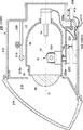
図1は、本発明の実施の形態に係る配光制御システムにおいて用いられる車両用前照灯210の内部構造を示す概略断面図である。図1に示す車両用前照灯210は、車両の車幅方向の左右に1灯ずつ配置される配光可変式前照灯であり、その構造は実質的に左右同等なので代表して車両右側に配置される車両用前照灯210Rの構造を説明する。
FIG. 1 is a schematic cross-sectional view showing an internal structure of a
車両用前照灯210Rは、車両前方方向に開口部を有するランプボディ212と、ランプボディ212の開口部を覆う透明カバー214とで形成される灯室216を有する。灯室216には、光を車両前方方向に照射する灯具ユニット10が収納されている。灯具ユニット10の一部には、当該灯具ユニット10の揺動中心となるピボット機構218aを有するランプブラケット218が形成されている。ランプブラケット218はランプボディ212の内壁面に立設されたボディブラケット220とネジ等の締結部材によって接続されている。したがって、灯具ユニット10は、灯室216内の所定位置に固定されると共に、ピボット機構218aを中心として、例えば前傾姿勢または後傾姿勢等に姿勢変化可能となる。
The
また、灯具ユニット10の下面には、曲線道路走行時等に進行方向を照らす曲線道路用配光可変前照灯(Adaptive Front-lighing System:AFS)を構成するためのスイブルアクチュエータ222の回転軸222aが固定されている。スイブルアクチュエータ222は、車両側から提供される操舵量のデータや、ナビゲーションシステムから提供される走行道路の形状データ、前方車と自車の相対位置の関係等に基づいて灯具ユニット10をピボット機構218aを中心に進行方向に旋回(スイブル:swivel)させる。その結果、灯具ユニット10の照射範囲が車両の正面ではなく曲線道路のカーブの先に向き、運転者の前方視界を向上させる。スイブルアクチュエータ222は、例えばステッピングモータで構成することができる。なお、スイブル角度が固定値の場合には、ソレノイドなども利用可能である。
Further, on the lower surface of the
スイブルアクチュエータ222は、ユニットブラケット224に固定されている。ユニットブラケット224には、ランプボディ212の外部に配置されたレベリングアクチュエータ226が接続されている。レベリングアクチュエータ226は、例えばロッド226aを矢印M,N方向に伸縮させるモータなどで構成されている。ロッド226aが矢印M方向に伸長した場合、灯具ユニット10はピボット機構218aを中心として後傾姿勢になるように揺動する。逆にロッド226aが矢印N方向に短縮した場合、灯具ユニット10はピボット機構218aを中心として前傾姿勢になるように揺動する。灯具ユニット10が後傾姿勢になると、光軸を上方に向けるレベリング調整ができる。また、灯具ユニット10が前傾姿勢になると、光軸を下方に向けるレベリング調整ができる。このようにレベリング調整をすることで、車両姿勢に応じた光軸調整ができる。その結果、車両用前照灯210による前方照射の到達距離を最適な距離に調整することができる。
The
なお、このレベリング調整は、車両走行中の車両姿勢に応じて実行することもできる。例えば、車両が走行中に加速する場合は後傾姿勢となり、逆に減速する場合は前傾姿勢となる。したがって、車両用前照灯210の照射方向も車両の姿勢状態に対応して上下に変動して、前方照射距離が長くなったり短くなったりする。そこで、車両姿勢に基づき灯具ユニット10のレベリング調整をリアルタイムで実行することで、走行中でも前方照射の到達距離を最適に調整できる。これを「オートレベリング」と称することもある。
This leveling adjustment can also be executed in accordance with the vehicle posture while the vehicle is running. For example, when the vehicle accelerates while traveling, it is in a backward leaning posture, and conversely, when it is decelerated, it is in a forward leaning posture. Therefore, the irradiation direction of the
灯室216の内壁面、例えば、灯具ユニット10の下方位置には、灯具ユニット10の点消灯制御や配光パターンの形成制御を実行する照射制御部228が配置されている。図1の場合、車両用前照灯210Rを制御するための照射制御部228Rが配置されている。この照射制御部228Rは、スイブルアクチュエータ222、レベリングアクチュエータ226等の制御も実行する。
On the inner wall surface of the
灯具ユニット10は、エーミング調整機構を備えることができる。例えば、レベリングアクチュエータ226のロッド226aとユニットブラケット224の接続部分に、エーミング調整時の揺動中心となるエーミングピボット機構を配置する。また、ボディブラケット220とランプブラケット218の接続部分に、車両前後方向に進退する一対のエーミング調整ネジを車幅方向に間隔をあけて配置する。例えば2本のエーミング調整ネジを前方に進出させれば、灯具ユニット10はエーミングピボット機構を中心に前傾姿勢となり光軸が下方に調整される。同様に2本のエーミング調整ネジを後方に引き戻せば、灯具ユニット10はエーミングピボット機構を中心に後傾姿勢となり光軸が上方に調整される。また、車幅方向左側のエーミング調整ネジを前方に進出させれば、灯具ユニット10はエーミングピボット機構を中心に右旋回姿勢となり右方向に光軸が調整される。また、車幅方向右側のエーミング調整ネジを前方に進出させれば、灯具ユニット10はエーミングピボット機構を中心に左旋回姿勢となり左方向に光軸が調整される。このエーミング調整は、車両出荷時や車検時、車両用前照灯210の交換時に行われる。そして、車両用前照灯210が設計上定められた規定の姿勢に調整され、この姿勢を基準に本実施形態の配光パターンの形成制御が行われる。
The
灯具ユニット10は、回転シェード12を含むシェード機構18と、光源としてのバルブ14と、リフレクタ16を内壁に支持する灯具ハウジング17と、投影レンズ20とを備える。バルブ14は、例えば、白熱球やハロゲンランプ、放電球、LEDなどが使用可能である。本実施の形態では、バルブ14をハロゲンランプで構成する例を示す。リフレクタ16は、バルブ14から放射される光を反射する。そして、バルブ14からの光およびリフレクタ16で反射した光は、その一部がシェード機構18を構成する回転シェード12を経て投影レンズ20へと導かれる。
The
図2は、回転シェード12の概略斜視図である。回転シェード12は、回転軸12aを中心に回転可能な円筒形状の部材である。また、回転シェード12は軸方向に一部が切り欠かれた切欠部22を有し、当該切欠部22以外の外周面12b上に板状のシェードプレート24を複数保持している。回転シェード12は、その回転角度に応じて投影レンズ20の後方焦点を含む後方焦点面の位置に切欠部22または、複数のシェードプレート24のいずれか1つを移動させることができる。そして、回転シェード12の回転角度に対応して光軸O上に位置するシェードプレート24の稜線部の形状に従う配光パターンが形成される。例えば、複数のシェードプレート24のいずれか1つを光軸O上に移動させてバルブ14から照射された光の一部を遮光することで、ロービーム用配光パターンまたは一部にロービーム用配光パターンの特徴を含む配光パターンを形成する。また、光軸O上に切欠部22を移動させてバルブ14から照射された光を非遮光とすることでハイビーム用配光パターンを形成する。
FIG. 2 is a schematic perspective view of the
回転シェード12は、シェードモータ(図示せず)により回転可能であり、該シェードモータの回転量を制御することで、回転所望の配光パターンを形成するためのシェードプレート24または切欠部22を光軸O上に移動させることができる。なお、回転シェード12の外周面12bの切欠部22を省略して、回転シェード12に、遮光機能だけを持たせてもよい。そして、ハイビーム用配光パターンを形成する場合は、例えばソレノイド等を駆動して回転シェード12を光軸Oの位置から退避させるようにする。このような構成にすることで、例えば、回転シェード12を回転させるシェードモータがフェールしてもロービーム用配光パターンまたはそれに類似する配光パターンで固定される。つまり、回転シェード12がハイビーム用配光パターンの形成姿勢で固定されてしまうことを確実に回避してフェールセーフ機能を実現できる。
The
投影レンズ20は、車両前後方向に延びる光軸O上に配置され、バルブ14は投影レンズ20の後方焦点面よりも後方側に配置される。投影レンズ20は、前方側表面が凸面で後方側表面が平面の平凸非球面レンズからなり、後方焦点面上に形成される光源像を反転像として車両用前照灯210前方の仮想鉛直スクリーン上に投影する。
The
図3(a)〜(f)は、本実施の形態に係る車両用前照灯210により照射可能な配光パターンを示す図である。図3(a)〜(f)は、車両用前照灯210の前方25mの位置に配置された仮想鉛直スクリーン上に形成される配光パターンを示している。なお、図3(a)〜(f)に示す配光パターンは、車幅方向の左右に配置された車両用前照灯210でそれぞれ形成した配光パターンを重畳させることで形成された合成配光パターンである。
FIGS. 3A to 3F are diagrams showing light distribution patterns that can be irradiated by the
図3(a)は、ロービーム用配光パターンLoを示している。このロービーム用配光パターンLoは、左側通行時に前方車や歩行者にグレアを与えないように配慮された配光パターンである。ロービーム用配光パターンLoは、その上端の鉛直線Vよりも右側に、水平線Hと平行に延びる対向車線側カットオフラインを、また鉛直線Vよりも左側に、対向車線側カットオフラインよりも高い位置で水平線Hと平行に延びる自車線側カットオフラインを、そして対向車線側カットオフラインと自車線側カットオフラインとの間に、両者をつなぐ斜めカットオフラインをそれぞれ有する。斜めカットオフラインは、対向車線側カットオフラインとV−V線との交点から左斜め上方へ45°の傾斜角で延びている。 FIG. 3A shows a low beam light distribution pattern Lo. This low beam light distribution pattern Lo is a light distribution pattern that is designed so as not to give glare to the forward vehicle or pedestrians when passing on the left side. The low beam light distribution pattern Lo is located on the right side of the top vertical line V on the opposite lane side cut-off line extending in parallel with the horizontal line H, and on the left side of the vertical line V higher than the opposite lane side cut-off line. And a lane-side cut-off line extending in parallel with the horizontal line H, and an oblique cut-off line connecting the lane-side cut-off line and the lane-side cut-off line. The diagonal cut-off line extends from the intersection of the opposite lane side cut-off line and the VV line diagonally upward to the left with an inclination angle of 45 °.
図3(b)は、ハイビーム用配光パターンHiを示している。このハイビーム用配光パターンHiは、前方の広範囲および遠方を照明する配光パターンであり、例えば、前方車や歩行者へのグレアを配慮する必要のない場合に形成される。 FIG. 3B shows a high beam light distribution pattern Hi. This high-beam light distribution pattern Hi is a light distribution pattern that illuminates a wide area in the front and a distant place, and is formed when, for example, it is not necessary to consider glare to the front car or pedestrian.
図3(c)は、交通法規が左側通行の地域で使用される左片ハイ用配光パターンLHiを示している。左片ハイ用配光パターンLHiは、左側通行時にハイビーム用配光パターンHiの対向車線側を遮光し、自車線側のみハイビーム領域で照射する特殊ハイビーム用配光パターンである。この左片ハイ用配光パターンLHiは、左側の車両用前照灯210で形成する左片ハイ用配光パターンと右側の車両用前照灯210で形成するロービーム用配光パターンとの合成によって形成される。このような左片ハイ用配光パターンLHiは、自車線側に前方車や歩行者が存在せず、対向車線側に対向車や歩行者が存在する場合に適した配光であり、運転者の前方視認性を向上させつつ、対向車や対向車線の歩行者にグレアを与えないように配慮した配光パターンである。
FIG. 3C shows a left high-side light distribution pattern LHi used in an area where traffic regulations are left-hand traffic. The left high-side light distribution pattern LHi is a special high-beam light distribution pattern that shields the opposite lane side of the high-beam light distribution pattern Hi during left-hand traffic and irradiates only the own lane side in the high-beam region. The left-side high light distribution pattern LHi is obtained by combining the left-side high light distribution pattern formed by the
図3(d)は、交通法規が左側通行の地域で使用される右片ハイ用配光パターンRHiを示している。右片ハイ用配光パターンRHiは、左側通行時にハイビーム用配光パターンHi1の自車線側を遮光し、対向車線側のみハイビーム領域で照射する特殊ハイビーム用配光パターンである。この右片ハイ用配光パターンRHiは、右側の車両用前照灯210で形成する右片ハイ用配光パターンと左側の車両用前照灯210で形成するロービーム用配光パターンとの合成によって形成される。右片ハイ用配光パターンRHiは、自車線側に前方車や歩行者が存在し、対向車線側に対向車や歩行者が存在しない場合に適した配光であり、運転者の前方視認性を向上させつつ、前方車や自車線の歩行者にグレアを与えないように配慮した配光パターンである。
FIG. 3D shows a right-side high light distribution pattern RHi used in an area where traffic regulations are left-hand traffic. The right-side high light distribution pattern RHi is a special high-beam light distribution pattern that shields the own-lane side of the high-beam light distribution pattern Hi1 during left-hand traffic and irradiates only the opposite lane side in the high-beam region. This right-side high light distribution pattern RHi is obtained by combining the right-side high light distribution pattern formed by the
図3(e)は、仮想鉛直スクリーン上の鉛直線Vと水平線Hの交点近傍に対する光の照射を抑制したVビーム用配光パターンLoVを示している。このVビーム用配光パターンLoVは、例えば、左側の車両用前照灯210により図3(a)に示すロービーム用配光パターンを形成する。一方、右側の車両用前照灯210により、交通法規が右側通行の地域で使用するロービーム用配光パターン、すなわち、図3(a)に示す配光パターンを鉛直線Vに関して線対称にした配光パターンを形成する。この2つ異なる配光パターンを重畳することにより、遠方の先行車や対向車が存在する可能性のある鉛直線Vと水平線Hの交点近傍に対する光の照射を抑制したVビーム用配光パターンLoVを形成することができる。このVビーム用配光パターンLoVは、遠方の前方車に対するグレアを抑制しつつ、自車線側や対向車線側の路肩の障害物などを運転者に認識させ易くできる配光パターンであるといえる。 FIG. 3E shows a V-beam light distribution pattern LoV in which light irradiation to the vicinity of the intersection of the vertical line V and the horizontal line H on the virtual vertical screen is suppressed. The V-beam light distribution pattern LoV forms, for example, a low-beam light distribution pattern shown in FIG. On the other hand, a low-beam light distribution pattern used in an area where traffic regulations are on the right side, that is, a light distribution pattern shown in FIG. A light pattern is formed. By superimposing these two different light distribution patterns, a V-beam light distribution pattern LoV that suppresses light irradiation to the vicinity of the intersection of the vertical line V and the horizontal line H in which a distant preceding vehicle or oncoming vehicle may exist. Can be formed. This V-beam light distribution pattern LoV can be said to be a light distribution pattern that makes it easier for the driver to recognize obstacles on the shoulders on the own lane side or on the opposite lane side while suppressing glare with respect to a far ahead vehicle.
図3(f)は、スプリット配光パターンSを示している。このスプリット配光パターンSは、水平線Hよりも上方の中央部に遮光領域UAを有し、遮光領域UAの水平方向両側にハイビーム領域を有する特殊ハイビーム用配光パターンである。スプリット配光パターンSは、左側の車両用前照灯210で形成した左片ハイ用配光パターンと、右側の車両用前照灯210で形成した右片ハイ用配光パターンとを重ね合わせることで形成することができる。スプリット配光パターンSを形成する際、左片ハイ用配光パターンのハイビーム領域と右片ハイ用配光パターンのハイビーム領域とが接しないように両配光パターンが重畳され、これにより遮光領域UAが形成される。
FIG. 3F shows the split light distribution pattern S. This split light distribution pattern S is a special high beam light distribution pattern having a light shielding area UA at the center above the horizontal line H and having high beam areas on both sides in the horizontal direction of the light shielding area UA. The split light distribution pattern S is obtained by superimposing the left-side high light distribution pattern formed by the
遮光領域UAは、左右の車両用前照灯210をスイブルさせて左片ハイ用配光パターンおよび右片ハイ用配光パターンの少なくとも一方を水平方向に移動させることで、水平方向にその範囲を変化させることができる。
The light shielding area UA is swiveled by moving the left and
図4は、本発明の実施の形態に係る配光制御システム100を説明するための機能ブロック図である。配光制御システム100は、上述した車両用前照灯210と、車両用前照灯210を制御する車両制御部302と、ライトスイッチ304と、カメラ306と、ステアリングセンサ308と、車速センサ310と、ナビゲーションシステム312とを備える。
FIG. 4 is a functional block diagram for explaining the light
車両用前照灯210の照射制御部228は、車両に搭載された車両制御部302の指示に従って電源回路230の制御を行い、バルブ14の点灯制御を実行する。また、照射制御部228は、車両制御部302からの指示に従い、レベリングアクチュエータ226、スイブルアクチュエータ222、シェードモータ221を制御する。
The
例えば、照射制御部228は、カーブ走行や右左折走行などの旋回時にスイブルアクチュエータ222を制御して、灯具ユニット10の光軸をこれから進行する方向に向ける。また、照射制御部228は、加減速時の車両姿勢の前傾、後傾に応じてレベリングアクチュエータ226を制御して、灯具ユニット10の光軸を車両上下方向について調整し、前方照射の到達距離を最適な距離に調整する。また、照射制御部228は、車両制御部302からの配光パターンの指示に応じて、レベリングアクチュエータ226、スイブルアクチュエータ222、シェードモータ221を制御する。
For example, the
配光制御システム100は、運転者によるライトスイッチ304の操作に応じて手動で配光パターンを切り替え可能である。以下、このような手動で配光パターンを制御するモードを、適宜「手動モード」と称する。例えば運転者がロービーム用配光パターンLoを選択した場合、車両制御部302は照射制御部228にロービーム用配光パターンLoを形成するよう指示を出す。指示を受けた照射制御部228は、ロービーム用配光パターンLoが形成されるようレベリングアクチュエータ226、スイブルアクチュエータ222、シェードモータ221を制御する。
The light
また、配光制御システム100は、ライトスイッチ304の操作によらず、車両周囲の状況を各種センサで検出して、車両周囲状況に最適な配光パターンを形成可能である。以下、このように配光パターンを制御するモードを、適宜「ADB(Adaptive Driving Beam)モード」と称する。
In addition, the light
ADBモードにおいては、例えば自車の前方に多数の前方車が検出された場合、車両制御部302は、これらの前方車へのグレアを防止するべきであると判断して、例えばロービーム用配光パターンLoが形成されるよう照射制御部228に指示を出す。また、前方車が検出されたが、前方車の周囲の視界を確保したい場合、車両制御部302は、前方車が遮光領域UAに含まれるスプリット配光パターンSが形成されるよう照射制御部228に指示を出す。このようにADBモードにおいては、前方車にグレアを与えることなく、自車前方の視界を出来るだけ確保するように配光パターンが選択される。
In the ADB mode, for example, when a large number of forward vehicles are detected in front of the host vehicle, the
このように前方車を検出するために、車両制御部302には対象物の認識手段として例えばステレオカメラなどのカメラ306が接続されている。カメラ306で撮像された画像データは、車両制御部302に送信され、車両制御部302が信号処理をして画像解析を行い、撮像範囲内における前方車を検知する。具体的には、車両制御部302は、カメラ306によって撮像された画像中において、対向車の前照灯または先行車のテールランプからの光によって形成された高輝度の光点を観測することにより前方車の検出を行っている。
In order to detect the vehicle ahead in this way, a
そして、車両制御部302は、取得した前方車の情報に基づいて最適な配光パターンを選択し、その選択した配光パターンを形成するように照射制御部228に指示を出す。なお、前方車を検出する手段は適宜変更可能であり、カメラ306に代えて、例えばミリ波レーダや赤外線レーダなど他の検出手段を用いてもよい。また、それらを組み合わせてもよい。
Then, the
また、車両制御部302は、車両に通常搭載されているステアリングセンサ308、車速センサ310などからの情報も取得可能であり、車両の走行状態や走行姿勢に応じて形成する配光パターンを選択したり、光軸の方向を変化させて簡易的に配光パターンを変化させることができる。例えば車両制御部302は、ステアリングセンサ308からの情報に基づき車両が旋回していると判定した場合、旋回方向の視界を向上させるような配光パターンが形成されるよう回転シェード12を回転制御する。また、シェード12の回転状態は変化させずに、スイブルアクチュエータ222を制御して灯具ユニット10の光軸を旋回方向に向けて視界を向上させるようにしてもよい。
The
この他、車両制御部302は、ナビゲーションシステム312から自車が走行している道路の形状情報や道路標識の設置情報などを取得することもできる。これらの情報を事前に取得することにより、レベリングアクチュエータ226、スイブルアクチュエータ222、シェードモータ221等を制御して、走行道路に適した配光パターンをスムーズに形成することもできる。
In addition, the
ところで、ADBモードにおいては、車両制御部302は、カメラ306によって撮像された画像中において高輝度の光点を観測することにより前方車の検出を行っているが、自車から遠方の前方車は光点の輝度が低下するため検出精度が低下する。また、カメラ306に代えて、例えばミリ波レーダや赤外線レーダなど他の検出手段を用いた場合も、遠方の前方車の検出精度は低下する。遠方の前方車の検出漏れが生じた場合、該前方車にグレアを与えてしまうおそれがある。そこで、本実施の形態においては、遠方の前方車にグレアを与えるのを防止できる手法を提供する。
By the way, in the ADB mode, the
図5は、遠方の前方車にグレアを与えるのを防止する手法を説明するための図である。図5は、車両が片側1車線(両側2車線)の直線舗装道路を走行している場合において、カメラ306の取り付け位置から車両前方路面を透視的に見て示す図に、車両用前照灯210から照射される光により車両前方25mの位置に配置された仮想鉛直スクリーン上に形成される配光パターンUdを重ねて示す図である。
FIG. 5 is a diagram for explaining a technique for preventing glare from being applied to a distant front vehicle. FIG. 5 is a view showing a vehicle front road surface seen through from a position where the
図5に示すように、車両前方路面には、その中央に位置するセンタラインLMcと、その両側に位置する左サイドラインLMs1、右サイドラインLMs2とが、車両走行レーンを仕切るレーンマークとして形成されている。センタラインLMcは、間欠的なレーンマークとして形成されており、左サイドラインLMs1、右サイドラインLMs2は、連続的なレーンマークとして形成されている。左サイドラインLMs1は、透視図の消失点であるH−V点(水平線Hと鉛直線Vとの交点)から左下方向に延びており、センタラインLMcおよび右サイドラインLMs2は、H−V点から右下方向に延びている。 As shown in FIG. 5, a center line LMc located at the center of the vehicle and a left side line LMs1 and a right side line LMs2 located on both sides thereof are formed as lane marks that divide the vehicle traveling lane. ing. The center line LMc is formed as intermittent lane marks, and the left side line LMs1 and the right side line LMs2 are formed as continuous lane marks. The left side line LMs1 extends in the lower left direction from the HV point (intersection of the horizontal line H and the vertical line V) that is the vanishing point of the perspective view, and the center line LMc and the right side line LMs2 are the HV point. It extends in the lower right direction.
上述したように、ADBモードにおいて、車両制御部302は、カメラ306で撮像された画像に基づいて前方車の検出を行う。そして、前方車が検出された場合は、該前方車にグレアを与えることなく、自車前方の視界を出来るだけ確保するような配光パターンを照射するよう照射制御部228に指示を出す。
As described above, in the ADB mode, the
一方、前方車が検出されなかった場合、車両制御部302は、図5に示す配光パターンUd(以下、前方車非検出時配光パターンUdと称する)を照射するよう照射制御部228に指示を出す。前方車非検出時配光パターンUdは、図3(f)に示したスプリット配光パターンSと類似した配光パターンであり、車両正面近傍(H−V点の近傍)への光の照射を抑制した遮光領域UBを有し、遮光領域UBの水平方向両側にハイビーム領域を有する。遮光領域UBは、水平方向に関しては鉛直線Vから左右に所定の角度αの範囲、鉛直方向に関しては水平線Hよりも上方の範囲である。鉛直方向に関しては、図5に示すように、遮光領域UBは水平線Hよりも若干下方に延びていてもよい。なお、角度αは、自車のカメラ306の取り付け位置からH−V点に延ばした線と、自車のカメラ取り付け位置から遮光領域UBと照射範囲との境界線BLに延ばした線とのなす角度で表される。鉛直線Vからの角度は、左右異ならせてもよい。また、遮光領域UBの位置を、車両の旋回情報に応じて左右方向に移動させてもよい。
On the other hand, when the front vehicle is not detected, the
図5に示すように遠方に前方車500が存在しているのにこの前方車500の検出を誤り、前方車が存在しないと判断してしまった場合、ハイビーム用配光パターンHiを照射すると、前方車500にグレアを与えてしまう。本実施の形態に係る配光制御システム100のように、前方車が検出されなかった場合に、ハイビーム用配光パターンHiに代えて車両正面近傍(H−V点の近傍)の範囲への光の照射を抑制した前方車非検出時配光パターンUdを照射することにより、前方車500にグレアを与えてしまう事態を防止できる。
As shown in FIG. 5, when the
前方車非検出時配光パターンUdにおける遮光領域UBの水平方向の幅を規定する角度αは、カメラ306の検知距離や、路肩歩行者の必要視認距離に基づいて設定することができる。例えば、検知距離の長いカメラ306であれば、角度αをより小さくすることができる。
The angle α that defines the width in the horizontal direction of the light blocking area UB in the light distribution pattern Ud when the front vehicle is not detected can be set based on the detection distance of the
一般に、車速が高速になるほど車間距離が広くなり、直線路を走行している可能性が高くなるため、前方車が移動する角度範囲が小さくなる。また、車速が高速になるほど郊外を走行している可能性が高く、車の数が少ないことが予想される。さらに、車速が高速になるほど、路肩の歩行者の必要視認距離が長くなる。このような点を踏まえ、車両制御部302は、車速センサ310によって検出された車速が高速になるほど、角度αを小さく設定してもよい。これにより、前方車にグレアを与えることなく、車両前方の視界を適切に確保することができる。さらに、路肩歩行者の必要視認距離を適切に確保することができる。
In general, as the vehicle speed increases, the inter-vehicle distance increases and the possibility of traveling on a straight road increases. Therefore, the angular range in which the preceding vehicle moves decreases. Also, the higher the vehicle speed, the higher the possibility of traveling in the suburbs, and it is expected that the number of vehicles will be small. Furthermore, the higher the vehicle speed, the longer the required viewing distance of the pedestrian on the road shoulder. In consideration of such points, the
また、一般に、郊外を走行している場合には市街地を走行している場合よりも車間距離が広くなりがちであるため、前方車が移動する角度範囲が小さくなる。また、郊外を走行している場合には市街地よりも車の数が少ないことが予想される。さらに、郊外においては市街地よりも車速が高速になるため、路肩の歩行者の必要視認距離が長くなる。このような点を踏まえ、車両制御部302は、ナビゲーションシステム312からの情報に基づき、車両が郊外を走行していることを検出した場合には、市街地を走行している場合よりも角度αを小さく設定してもよい。これにより、前方車にグレアを与えることなく、車両前方の視界を適切に確保することができる。さらに、路肩の歩行者の必要視認距離を適切に確保することができる。
In general, when traveling in a suburb, the inter-vehicle distance tends to be larger than when traveling in an urban area, so the angle range in which the preceding vehicle moves becomes smaller. Also, when driving in the suburbs, it is expected that there will be fewer cars than in the city. Furthermore, since the vehicle speed is higher in the suburbs than in the urban area, the required viewing distance for pedestrians on the shoulder becomes longer. Based on such points, when the
その他にも、環境に応じて検知精度が変わることを考慮して角度αを変更する方策は考えられる。例えば、カーブ路では直線路に比べて角度αを大きくする、悪天候時は晴天時よりも角度αを大きくする、周囲が明るいほど角度αを大きくする等の方策が考えられる。これらの方策のうち少なくとも1つを採用すれば、他車両へグレアを与える危険性を低くすることができる。 In addition, a method for changing the angle α in consideration of the change in detection accuracy depending on the environment is conceivable. For example, measures such as increasing the angle α on a curved road compared to a straight road, increasing the angle α during bad weather than when clear, and increasing the angle α as the surroundings are brighter are conceivable. If at least one of these measures is adopted, the risk of giving glare to other vehicles can be reduced.
本実施の形態に係る配光制御システム100は、遠方の前方車を検出精度を向上するために高価な超高感度カメラを用いる必要がないので、安価な構成により前走車にグレアを与えるのを防止できる配光制御システムを実現できる。
Since the light
なお、上述ようにハイビーム用配光パターンHiに代えて前方車非検出時配光パターンUdが照射されるのは、ADBモードの場合だけである。ライトスイッチ304により手動モードが選択されている場合に運転者がハイビーム用配光パターンを選択した場合、車両制御部302は、図3(b)に示す通常のハイビーム用配光パターンHiを照射するよう照射制御部228に指示を出す。
As described above, the light distribution pattern Ud when the front vehicle is not detected is irradiated instead of the high beam light distribution pattern Hi only in the ADB mode. When the driver selects the high beam light distribution pattern when the manual mode is selected by the
以上、実施の形態をもとに本発明を説明した。これらの実施形態は例示であり、各構成要素や各処理プロセスの組合せにいろいろな変形例が可能なこと、またそうした変形例も本発明の範囲にあることは当業者に理解されるところである。 The present invention has been described above based on the embodiment. It should be understood by those skilled in the art that these embodiments are exemplifications, and that various modifications can be made to the combination of each component and each processing process, and such modifications are also within the scope of the present invention.
12 回転シェード、 24 シェードプレート、 100 配光制御システム、 210 車両用前照灯、 221 シェードモータ、 222 スイブルアクチュエータ、 226 レベリングアクチュエータ、 228 照射制御部、 302 車両制御部、 304 ライトスイッチ、 306 カメラ。 12 rotating shades, 24 shade plates, 100 light distribution control systems, 210 vehicle headlamps, 221 shade motors, 222 swivel actuators, 226 leveling actuators, 228 irradiation control units, 302 vehicle control units, 304 light switches, 306 cameras.
Claims (2)
車両前方に存在する前方車を検出する検出手段と、
検出された前方車にグレアを与えない配光パターンを照射するよう前記車両用前照灯を制御する制御手段と、
車速を検出する車速検出手段と、
を備える車両用前照灯の配光制御システムであって、
前記制御手段は、前記検出手段により前方車が検出されなかった場合、車両正面近傍への光の照射を抑制した前方車非検出時配光パターンを照射し、
前記前方車非検出時配光パターンは、車両正面から所定の角度の範囲内における光の照射を抑制した配光パターンであり、
前記制御手段は、車速が高速になるほど、前記所定の角度を小さく設定する、
ことを特徴とする車両用前照灯の配光制御システム。 A vehicle headlamp capable of controlling a light distribution pattern irradiated to the front of the vehicle;
Detecting means for detecting a forward vehicle existing in front of the vehicle;
Control means for controlling the vehicle headlamp so as to irradiate a light distribution pattern that does not give glare to the detected forward vehicle;
Vehicle speed detection means for detecting the vehicle speed;
A vehicle headlamp light distribution control system comprising:
When the front vehicle is not detected by the detection unit, the control unit irradiates a front vehicle non-detection light distribution pattern that suppresses light irradiation to the vicinity of the front of the vehicle ,
The front vehicle non-detection light distribution pattern is a light distribution pattern that suppresses light irradiation within a predetermined angle range from the front of the vehicle,
The control means sets the predetermined angle smaller as the vehicle speed increases.
A light distribution control system for a vehicle headlamp.
車両前方に存在する前方車を検出する検出手段と、
検出された前方車にグレアを与えない配光パターンを照射するよう前記車両用前照灯を制御する制御手段と、
車両が走行している道路の情報を取得する道路情報取得手段と、
を備える車両用前照灯の配光制御システムであって、
前記制御手段は、前記検出手段により前方車が検出されなかった場合、車両正面近傍への光の照射を抑制した前方車非検出時配光パターンを照射し、
前記前方車非検出時配光パターンは、車両正面から所定の角度の範囲内における光の照射を抑制した配光パターンであり、
前記制御手段は、車両が郊外を走行している場合には、市街地を走行している場合よりも前記所定の角度を小さく設定することを特徴とする車両用前照灯の配光制御システム。 A vehicle headlamp capable of controlling a light distribution pattern irradiated to the front of the vehicle;
Detecting means for detecting a forward vehicle existing in front of the vehicle;
Control means for controlling the vehicle headlamp so as to irradiate a light distribution pattern that does not give glare to the detected forward vehicle;
Road information acquisition means for acquiring information on the road on which the vehicle is traveling ;
A vehicle headlamp light distribution control system comprising:
When the front vehicle is not detected by the detection unit, the control unit irradiates a front vehicle non-detection light distribution pattern that suppresses light irradiation to the vicinity of the front of the vehicle,
The front vehicle non-detection light distribution pattern is a light distribution pattern that suppresses light irradiation within a predetermined angle range from the front of the vehicle,
The control means, the vehicle when the vehicle is traveling the suburbs, the light distribution control system of the car dual headlamp and sets smaller the predetermined angle than when the vehicle is traveling in an urban area .
Priority Applications (1)
| Application Number | Priority Date | Filing Date | Title |
|---|---|---|---|
| JP2009185039A JP5430282B2 (en) | 2009-08-07 | 2009-08-07 | Light distribution control system for vehicle headlamps |
Applications Claiming Priority (1)
| Application Number | Priority Date | Filing Date | Title |
|---|---|---|---|
| JP2009185039A JP5430282B2 (en) | 2009-08-07 | 2009-08-07 | Light distribution control system for vehicle headlamps |
Publications (2)
| Publication Number | Publication Date |
|---|---|
| JP2011037343A JP2011037343A (en) | 2011-02-24 |
| JP5430282B2 true JP5430282B2 (en) | 2014-02-26 |
Family
ID=43765602
Family Applications (1)
| Application Number | Title | Priority Date | Filing Date |
|---|---|---|---|
| JP2009185039A Expired - Fee Related JP5430282B2 (en) | 2009-08-07 | 2009-08-07 | Light distribution control system for vehicle headlamps |
Country Status (1)
| Country | Link |
|---|---|
| JP (1) | JP5430282B2 (en) |
Families Citing this family (7)
| Publication number | Priority date | Publication date | Assignee | Title |
|---|---|---|---|---|
| JP5844074B2 (en) * | 2011-06-16 | 2016-01-13 | 株式会社小糸製作所 | Vehicle headlight control device |
| JP5989429B2 (en) * | 2012-07-06 | 2016-09-07 | シャープ株式会社 | Lighting device and vehicle headlamp |
| JP6022204B2 (en) * | 2012-05-09 | 2016-11-09 | シャープ株式会社 | Lighting device and vehicle headlamp |
| US9534756B2 (en) | 2012-04-03 | 2017-01-03 | Sharp Kabushiki Kaisha | Light-emitting device, floodlight, and vehicle headlight |
| JP2014004922A (en) * | 2012-06-25 | 2014-01-16 | Denso Corp | Head lamp light distribution control device for vehicle |
| JP6816701B2 (en) * | 2017-10-26 | 2021-01-20 | トヨタ自動車株式会社 | Headlight control system |
| CN113531474B (en) * | 2020-04-17 | 2022-08-05 | 华域视觉科技(上海)有限公司 | Anti-dazzling high beam and vehicle |
Family Cites Families (2)
| Publication number | Priority date | Publication date | Assignee | Title |
|---|---|---|---|---|
| JP4708285B2 (en) * | 2006-08-04 | 2011-06-22 | トヨタ自動車株式会社 | Vehicle headlamp |
| JP4484856B2 (en) * | 2006-10-06 | 2010-06-16 | 日立オートモティブシステムズ株式会社 | Automotive headlight controller |
-
2009
- 2009-08-07 JP JP2009185039A patent/JP5430282B2/en not_active Expired - Fee Related
Also Published As
| Publication number | Publication date |
|---|---|
| JP2011037343A (en) | 2011-02-24 |
Similar Documents
| Publication | Publication Date | Title |
|---|---|---|
| JP5424771B2 (en) | Light distribution control system for vehicle headlamps | |
| JP5833861B2 (en) | Vehicle headlamp device and light distribution control method | |
| JP5398443B2 (en) | Vehicle headlamp device | |
| JP5372616B2 (en) | Light distribution control system for vehicle headlamps | |
| JP5362460B2 (en) | Vehicle headlamp device | |
| JP5438405B2 (en) | Vehicle headlamp device | |
| JP5546326B2 (en) | Control device, vehicle lamp system, vehicle lamp | |
| JP2011020559A (en) | Vehicular headlamp apparatus | |
| JP5430282B2 (en) | Light distribution control system for vehicle headlamps | |
| JP2011031808A (en) | Light distribution control system of vehicular headlamp | |
| JP5552381B2 (en) | Control device, vehicle headlamp system | |
| JP2011255825A (en) | Vehicular lighting fixture system, control device and vehicular lighting fixture | |
| JP2012162105A (en) | Vehicular headlight device | |
| JP5539796B2 (en) | Vehicle headlight system | |
| JP5405201B2 (en) | Vehicle headlamp system and method for associating lamp unit with photographing unit | |
| JP5317871B2 (en) | Vehicle headlamp device | |
| EP2388164B1 (en) | Vehicle Headlamp system, control device, vehicle headlamp, and control method of vehicle headlamp | |
| JP5563884B2 (en) | Control device, vehicle lamp system, vehicle lamp | |
| JP2011240870A (en) | Vehicle headlamp system, control device, and vehicle headlamp | |
| JP5636483B2 (en) | Light distribution control system for vehicle headlamps | |
| EP2384933B1 (en) | Vehicle headlamp system, control device and vehicle headlamp | |
| JP2010015837A (en) | Headlight device for vehicle | |
| JP5557611B2 (en) | VEHICLE LIGHT SYSTEM, CONTROL DEVICE, AND VEHICLE LIGHT | |
| JP5530125B2 (en) | Vehicle headlamp device | |
| JP2011238378A (en) | Lamp fixture system for vehicle, control device, and lamp fixture for vehicle |
Legal Events
| Date | Code | Title | Description |
|---|---|---|---|
| A621 | Written request for application examination |
Free format text: JAPANESE INTERMEDIATE CODE: A621 Effective date: 20120711 |
|
| A977 | Report on retrieval |
Free format text: JAPANESE INTERMEDIATE CODE: A971007 Effective date: 20130726 |
|
| A131 | Notification of reasons for refusal |
Free format text: JAPANESE INTERMEDIATE CODE: A131 Effective date: 20130806 |
|
| A521 | Written amendment |
Free format text: JAPANESE INTERMEDIATE CODE: A523 Effective date: 20130919 |
|
| TRDD | Decision of grant or rejection written | ||
| A01 | Written decision to grant a patent or to grant a registration (utility model) |
Free format text: JAPANESE INTERMEDIATE CODE: A01 Effective date: 20131126 |
|
| A61 | First payment of annual fees (during grant procedure) |
Free format text: JAPANESE INTERMEDIATE CODE: A61 Effective date: 20131203 |
|
| R150 | Certificate of patent or registration of utility model |
Free format text: JAPANESE INTERMEDIATE CODE: R150 Ref document number: 5430282 Country of ref document: JP Free format text: JAPANESE INTERMEDIATE CODE: R150 |
|
| LAPS | Cancellation because of no payment of annual fees |