WO2021166749A1 - 学習装置及び医療用画像処理装置 - Google Patents
学習装置及び医療用画像処理装置 Download PDFInfo
- Publication number
- WO2021166749A1 WO2021166749A1 PCT/JP2021/004847 JP2021004847W WO2021166749A1 WO 2021166749 A1 WO2021166749 A1 WO 2021166749A1 JP 2021004847 W JP2021004847 W JP 2021004847W WO 2021166749 A1 WO2021166749 A1 WO 2021166749A1
- Authority
- WO
- WIPO (PCT)
- Prior art keywords
- region
- image
- light
- singular
- feature amount
- Prior art date
- Legal status (The legal status is an assumption and is not a legal conclusion. Google has not performed a legal analysis and makes no representation as to the accuracy of the status listed.)
- Ceased
Links
Images



Classifications
-
- A—HUMAN NECESSITIES
- A61—MEDICAL OR VETERINARY SCIENCE; HYGIENE
- A61B—DIAGNOSIS; SURGERY; IDENTIFICATION
- A61B1/00—Instruments for performing medical examinations of the interior of cavities or tubes of the body by visual or photographical inspection, e.g. endoscopes; Illuminating arrangements therefor
- A61B1/00002—Operational features of endoscopes
- A61B1/00004—Operational features of endoscopes characterised by electronic signal processing
- A61B1/00009—Operational features of endoscopes characterised by electronic signal processing of image signals during a use of endoscope
- A61B1/000096—Operational features of endoscopes characterised by electronic signal processing of image signals during a use of endoscope using artificial intelligence
-
- A—HUMAN NECESSITIES
- A61—MEDICAL OR VETERINARY SCIENCE; HYGIENE
- A61B—DIAGNOSIS; SURGERY; IDENTIFICATION
- A61B1/00—Instruments for performing medical examinations of the interior of cavities or tubes of the body by visual or photographical inspection, e.g. endoscopes; Illuminating arrangements therefor
- A61B1/00002—Operational features of endoscopes
- A61B1/00004—Operational features of endoscopes characterised by electronic signal processing
- A61B1/00009—Operational features of endoscopes characterised by electronic signal processing of image signals during a use of endoscope
- A61B1/000094—Operational features of endoscopes characterised by electronic signal processing of image signals during a use of endoscope extracting biological structures
-
- A—HUMAN NECESSITIES
- A61—MEDICAL OR VETERINARY SCIENCE; HYGIENE
- A61B—DIAGNOSIS; SURGERY; IDENTIFICATION
- A61B1/00—Instruments for performing medical examinations of the interior of cavities or tubes of the body by visual or photographical inspection, e.g. endoscopes; Illuminating arrangements therefor
- A61B1/04—Instruments for performing medical examinations of the interior of cavities or tubes of the body by visual or photographical inspection, e.g. endoscopes; Illuminating arrangements therefor combined with photographic or television appliances
- A61B1/043—Instruments for performing medical examinations of the interior of cavities or tubes of the body by visual or photographical inspection, e.g. endoscopes; Illuminating arrangements therefor combined with photographic or television appliances for fluorescence imaging
-
- A—HUMAN NECESSITIES
- A61—MEDICAL OR VETERINARY SCIENCE; HYGIENE
- A61B—DIAGNOSIS; SURGERY; IDENTIFICATION
- A61B1/00—Instruments for performing medical examinations of the interior of cavities or tubes of the body by visual or photographical inspection, e.g. endoscopes; Illuminating arrangements therefor
- A61B1/06—Instruments for performing medical examinations of the interior of cavities or tubes of the body by visual or photographical inspection, e.g. endoscopes; Illuminating arrangements therefor with illuminating arrangements
- A61B1/0638—Instruments for performing medical examinations of the interior of cavities or tubes of the body by visual or photographical inspection, e.g. endoscopes; Illuminating arrangements therefor with illuminating arrangements providing two or more wavelengths
-
- A—HUMAN NECESSITIES
- A61—MEDICAL OR VETERINARY SCIENCE; HYGIENE
- A61B—DIAGNOSIS; SURGERY; IDENTIFICATION
- A61B1/00—Instruments for performing medical examinations of the interior of cavities or tubes of the body by visual or photographical inspection, e.g. endoscopes; Illuminating arrangements therefor
- A61B1/06—Instruments for performing medical examinations of the interior of cavities or tubes of the body by visual or photographical inspection, e.g. endoscopes; Illuminating arrangements therefor with illuminating arrangements
- A61B1/0655—Control therefor
Definitions
- This disclosure relates to a learning device and a medical image processing device.
- a rigid mirror system in which a fluorescent substance such as indocyanine green is administered into a living body, and an excitation light that excites the fluorescent substance is irradiated to the observation target to fluorescently observe the lesion portion where the fluorescent substance is accumulated.
- a fluorescent substance such as indocyanine green
- Patent Document 1 the following first and second captured images are acquired, and the first and second captured images are superposed on the corresponding pixels to generate a superposed image.
- the first captured image is an image obtained by irradiating an observation target with normal light, which is white light, and capturing the normal light reflected by the observation target with an image sensor.
- the second captured image is an image obtained by irradiating the observation target with excitation light that excites a fluorescent substance such as indocyanine green, and capturing the fluorescence from the observation target excited by the excitation light with a high-sensitivity imaging device.
- a fluorescent region emitted from an observation target (hereinafter referred to as a fluorescent region)
- a fluorescent substance such as indocyanine green is in vivo. Need to be administered. For example, if the fluorescence region can be estimated from the first captured image without performing the administration, the convenience can be improved.
- the present disclosure has been made in view of the above, and an object of the present disclosure is to provide a learning device and a medical image processing device capable of improving convenience.
- the learning apparatus includes a first teacher image obtained by capturing light from a subject irradiated with light in the first wavelength band, and the first teacher image described above.
- a teacher image acquisition unit that acquires a teacher image as a set of a second teacher image that captures light from the subject irradiated with light in a second wavelength band different from the first wavelength band, and the above. Extraction of the first feature amount to extract the feature amount of the peculiar region specifying part for specifying the peculiar region in the second teacher image and the peculiar corresponding region of the pixel position corresponding to the peculiar region in the first teacher image.
- a unit and a specific correspondence area learning unit that machine-learns the specific correspondence region based on the feature amount to generate a learning model.
- the subject is a subject that fluoresces when irradiated with excitation light in the second wavelength band
- the second teacher image is a subject. It is an image of the fluorescence from the subject irradiated with the excitation light
- the specific region specifying portion is a region in which the intensity of the fluorescence component is equal to or higher than a specific threshold in the second teacher image. Is specified as the singular region.
- the singular region specifying unit specifies a region in which the pixel level is equal to or higher than a specific threshold value as the singular region in the second teacher image.
- the singular region specifying portion has, as the singular region, a first singular region in which the pixel level is within the first range and the first singular region having a pixel level.
- Each of the second singular region, which is within the second range higher than the range, is specified, and the first feature amount extraction unit is the first singular corresponding region in the first teacher image.
- Each feature amount is extracted, and the peculiar correspondence area learning unit machine-learns the first peculiar correspondence area and the second peculiar correspondence area based on the feature amount.
- the feature amount includes a feature amount relating to at least one of color and brightness
- the peculiar correspondence area learning unit machine-learns the peculiar correspondence area and learns a model.
- the weight of the feature amount with respect to the blue color component is made lower than the weight of the feature amount with respect to other color components.
- the light in the first wavelength band is the light emitted in the first period in the first period and the second period which are alternately repeated.
- the light in the second wavelength band is the light emitted during the second period.
- the medical image processing apparatus includes an image capture image acquisition unit that acquires an image captured by capturing light from an observation target irradiated with light in the first wavelength band, and features for each region in the image. It is provided with a second feature quantity extraction unit for extracting the quantity, and a specific correspondence region identification unit for specifying the specific correspondence region in the captured image by using a learning model constructed by machine learning based on the feature quantity.
- a learning model constructed by machine learning based on the feature quantity.
- a teacher image as a set with the second teacher image obtained by capturing the light from the subject, the pixel position corresponding to the singular region in the second teacher image in the first teacher image.
- This is a learning model generated by machine learning the specific correspondence region based on the feature amount of the specific correspondence region.
- the subject is a subject that fluoresces when irradiated with excitation light in the second wavelength band, and the second teacher.
- the image is an image obtained by imaging the fluorescence from the subject irradiated with the excitation light, and in the specific region, the intensity of the fluorescence component in the second teacher image is equal to or higher than a specific threshold value. The area.
- the singular region is a region in which the pixel level is equal to or higher than a specific threshold value in the second teacher image.
- the singular region has a first singular region in which the pixel level is within the first range and a pixel level higher than the first range.
- the learning model includes a second singular region that falls within the second range, and the learning model is a first pixel position corresponding to the first singular region that is the singular corresponding region in the first teacher image.
- the first singularity is based on the feature quantities of the singularity-corresponding region and the second singularity-corresponding region of the pixel position corresponding to the second singularity region, which is the singularity-corresponding region in the first teacher image. This is a learning model generated by machine learning each of the corresponding region and the second singular corresponding region.
- the feature amount includes a feature amount relating to at least one of color and brightness
- the learning model weights the feature amount relating to a blue color component. This is a learning model generated by machine learning the singular correspondence region with the weight of the feature amount related to other color components lowered.
- the light in the first wavelength band emits light in the first period in the first period and the second period which are alternately repeated.
- the light in the second wavelength band is the light emitted during the second period.
- the medical image processing apparatus further includes a display control unit that generates a display image that distinguishes and displays the peculiar corresponding region from other regions in the captured image.
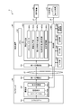
- FIG. 1 is a diagram showing a configuration of a learning system according to an embodiment.
- FIG. 2 is a diagram showing a configuration of a teacher image generator.
- FIG. 3 is a diagram showing a configuration of a camera head and a control device.
- FIG. 4 is a flowchart showing the operation of the teacher image generator.
- FIG. 5 is a diagram illustrating the operation of the teacher image generator.
- FIG. 6 is a diagram illustrating the operation of the teacher image generator.
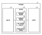
- FIG. 7 is a diagram showing the configuration of the learning device.
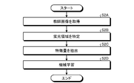
- FIG. 8 is a flowchart showing the operation of the learning device.
- FIG. 9 is a diagram showing a configuration of a medical observation device.
- FIG. 10 is a diagram showing a configuration of a camera head and a control device.
- FIG. 11 is a flowchart showing the operation of the medical observation device.
- FIG. 12 is a diagram illustrating the operation of the medical observation device.
- FIG. 1 is a diagram showing a configuration of a learning system 1 according to the present embodiment.
- the learning system 1 is a system that generates a learning model used for estimating a fluorescence region (unique region) in which fluorescence is emitted when an observation target is irradiated with near-infrared excitation light.
- the learning system 1 includes a teacher image generation device 2 and a learning device 3.
- the teacher image generation device 2 and the learning device 3 communicate by wire or wirelessly via the network NE (FIG. 1).
- the number of the teacher image generator 2 is not limited to one, and may be a plurality of teacher image generators 2.
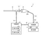
- FIG. 2 is a diagram showing the configuration of the teacher image generation device 2.
- the teacher image generation device 2 is a device that generates a teacher image used for machine learning in the learning device 3.
- the teacher image generation device 2 includes an insertion unit 21, a light source device 22, a light guide 23, a camera head 24, a first transmission cable 25, a display device 26, and a second.
- the transmission cable 27, the control device 28, and the third transmission cable 29 are provided.
- the insertion portion 21 is a rigid endoscope. That is, the insertion portion 21 has an elongated shape in which the whole is hard, or a part is soft and the other part is hard, and the insertion portion 21 is inserted into the living body.
- the insertion portion 21 is configured by using one or a plurality of lenses, and is provided with an optical system that collects light from the living body (subject).
- the light source device 22 is connected to one end of the light guide 23, and under the control of the control device 28, supplies light to irradiate the living body to one end of the light guide 23.
- the light source device 22 includes a first light source 221 and a second light source 222.
- the first light source 221 emits (emits) normal light in the first wavelength band.
- the first light source 221 is composed of an LED (Light Emitting Diode) that emits white light.
- the second light source 222 emits (emits) excitation light in a second wavelength band different from the first wavelength band.
- it is composed of a semiconductor laser that emits near-infrared excitation light in the near-infrared wavelength band.
- the near-infrared excitation light is excitation light that excites a fluorescent substance such as indocyanine green. Further, when the fluorescent substance such as indocyanine green is excited by the near-infrared excitation light, it emits fluorescence having a center wavelength on the longer wavelength side than the center wavelength of the wavelength band of the near-infrared excitation light.
- the wavelength band of the near-infrared excitation light and the wavelength band of the fluorescence may be set so as to partially overlap each other, or may be set so as not to overlap at all.
- the first light source 221 is driven in the first period of the first and second periods that are alternately repeated under the control of the control device 28. That is, in the first period, the light source device 22 emits normal light (white light).
- the second light source 222 is driven in the second period under the control of the control device 28. That is, in the second period, the light source device 22 emits near-infrared excitation light.
- the light source device 22 is configured separately from the control device 28, but the present invention is not limited to this, and a configuration provided inside the control device 28 may be adopted.
- One end of the light guide 23 is detachably connected to the light source device 22, and the other end is detachably connected to the insertion portion 21. Then, the light guide 23 transmits the light (normal light or near-infrared excitation light) supplied from the light source device 22 from one end to the other end and supplies the light to the insertion portion 21.
- the light guide 23 transmits the light (normal light or near-infrared excitation light) supplied from the light source device 22 from one end to the other end and supplies the light to the insertion portion 21.
- the normal light reflected in the living body is condensed by the optical system in the insertion portion 21.
- the normal light focused by the optical system in the insertion portion 21 will be referred to as a first subject image.
- the near-infrared excitation light reflected in the living body and a fluorescent substance such as indocyanine green accumulated in the lesion portion in the living body are excited. Then, the fluorescence emitted from the fluorescent substance is collected by the optical system in the insertion portion 21.
- the fluorescence transmitted through the excitation light cut filter 242a described later is referred to as a second subject image. Describe.
- the camera head 24 is detachably connected to the base end (eyepiece portion 211 (FIG. 2)) of the insertion portion 21. Then, the camera head 24 captures a first subject image (normal light) and a second subject image (fluorescence) under the control of the control device 28, and outputs an image signal (RAW signal) obtained by the imaging.
- the image signal is, for example, an image signal of 4K or more.
- the detailed configuration of the camera head 24 will be described in "2-1. Configuration of the camera head" described later.
- One end of the first transmission cable 25 is detachably connected to the control device 28 via the connector CN1 (FIG. 2), and the other end is detachably connected to the camera head 24 via the connector CN2 (FIG. 2).
- the first transmission cable 25 transmits the image signal and the like output from the camera head 24 to the control device 28, and also transmits the control signal, the synchronization signal, the clock, the electric power and the like output from the control device 28 to the camera head. It is transmitted to 24 respectively.
- the image signal or the like may be transmitted from the camera head 24 to the control device 28 via the first transmission cable 25 by an optical signal or an electric signal. I do not care. The same applies to the transmission of the control signal, the synchronization signal, and the clock from the control device 28 to the camera head 24 via the first transmission cable 25.
- the display device 26 is composed of a display display using a liquid crystal display, an organic EL (Electro Luminescence), or the like, and displays an image based on a video signal from the control device 28 under the control of the control device 28.
- One end of the second transmission cable 27 is detachably connected to the display device 26, and the other end is detachably connected to the control device 28. Then, the second transmission cable 27 transmits the video signal processed by the control device 28 to the display device 26.
- the control device 28 is composed of a CPU (Central Processing Unit), an FPGA (Field-Programmable Gate Array), and the like, and comprehensively controls the operations of the light source device 22, the camera head 24, and the display device 26.
- the detailed configuration of the control device 28 will be described in "2-2. Configuration of the control device” described later.
- One end of the third transmission cable 29 is detachably connected to the light source device 22, and the other end is detachably connected to the control device 28. Then, the third transmission cable 29 transmits the control signal from the control device 28 to the light source device 22.
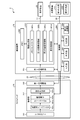
- FIG. 3 is a diagram showing the configuration of the camera head 24 and the control device 28.
- the connector, the control device 28, and the connector between the light source device 22 and the third transmission cable 29 are not shown.
- the camera head 24 includes a lens unit 241, an imaging unit 242, and a first communication unit 243.
- the lens unit 241 is configured by using one or a plurality of lenses, and forms a first subject image (normal light) and a second subject image (fluorescence) on the imaging surface of the imaging unit 242 (imaging element 242b). ..
- the imaging unit 242 images the inside of the living body under the control of the control device 28.
- the image pickup unit 242 includes an excitation light cut filter 242a, an image pickup element 242b, and a signal processing unit 242c.
- the excitation light cut filter 242a is provided between the lens unit 241 and the image pickup device 242b, and is composed of a band stop filter that removes a specific wavelength band. That is, the excitation light cut filter 242a is arranged on the optical path of the near-infrared excitation light reflected in the living body from the living body to the image sensor 242b.
- the wavelength band cut (removed) by the excitation light cut filter 242a is described as a cut band, and the wavelength band is shorter than the cut band and is transmitted through the excitation light cut filter 242a.
- the wavelength band is described as the short wave side transmission band, and the wavelength band on the long wavelength side of the cut band and transmitted through the excitation light cut filter 242a is described as the long wave side transmission band.
- the cut band includes at least a part of the wavelength band of the near-infrared excitation light.
- the cut band includes the entire wavelength band of the near-infrared excitation light.
- the long wave side transmission band includes the entire wavelength band of fluorescence.
- the short wave side transmission band includes the entire wavelength band of normal light (white light). That is, the excitation light cut filter 242a transmits the first subject image (normal light (white light)) from the lens unit 241 toward the image sensor 242b.
- the excitation light cut filter 242a cuts (removes) the near-infrared excitation light and fluorescence from the lens unit 241 toward the image pickup element 242b, and transmits the fluorescence (second subject image). Let me.
- the image sensor 242b is composed of a CCD (Charge Coupled Device) or CMOS (Complementary Metal Oxide Semiconductor) that receives light transmitted through the excitation light cut filter 242a and converts it into an electric signal (analog signal).
- CCD Charge Coupled Device
- CMOS Complementary Metal Oxide Semiconductor
- a color filter 242d (FIG. 3) arranged in a predetermined format (for example, a bayer arrangement) is provided. Specifically, the color filter 242d mainly transmits the R filter group that mainly transmits the light in the R wavelength band, the B filter group that mainly transmits the light in the B wavelength band, and the light in the G wavelength band.
- a first G filter group to transmit (arranged in the same row as the R filter group) and a second G filter group (arranged in the same row as the B filter group) to mainly transmit light in the G wavelength band.
- the first and second G filter groups are collectively referred to as a G filter group.
- each of the R, G, and B filter groups also transmits fluorescence.
- the image sensor 242b has sensitivity not only to light in the wavelength bands of R, G, and B, but also to light in the wavelength band of fluorescence.
- the image pickup device 242b performs imaging every first and second periods that are alternately repeated in synchronization with the light emission timing of the light source device 22.
- the image generated by capturing the first subject image (normal light) in the first period with the image sensor 242b is described as the first teacher image
- the second image sensor 242b describes the image as the first teacher image.
- the image generated by capturing the second subject image (fluorescence) during the period of 1 is referred to as the second teacher image.
- the first and second teacher images are collectively referred to as a teacher image.
- the signal processing unit 242c performs signal processing on the teacher image (analog signal) generated by the image pickup element 242b and outputs the teacher image (RAW signal (digital signal)).
- the first communication unit 243 functions as a transmitter that transmits a teacher image (RAW signal (digital signal)) output from the image pickup unit 242 to the control device 28 via the first transmission cable 25.
- the first communication unit 243 is configured by, for example, a high-speed serial interface that communicates a teacher image with a control device 28 at a transmission rate of 1 Gbps or more via a first transmission cable 25.
- control device configuration Next, the configuration of the control device 28 will be described with reference to FIG. As shown in FIG. 3, the control device 28 includes a second communication unit 281, a memory 282, an image generation unit 283, a control unit 284, an input unit 285, an output unit 286, and a storage unit 287. A third communication unit 288 is provided.
- the second communication unit 281 functions as a receiver that receives a teacher image (RAW signal (digital signal)) output from the camera head 24 (first communication unit 243) via the first transmission cable 25. ..
- the second communication unit 281 is configured by, for example, a high-speed serial interface that communicates a teacher image with the first communication unit 243 at a transmission rate of 1 Gbps or more.
- the memory 282 is composed of, for example, a DRAM (Dynamic Random Access Memory) or the like. The memory 282 can temporarily store a plurality of frames of teacher images sequentially output from the camera head 24 (first communication unit 243).
- the image generation unit 283 is sequentially output from the camera head 24 (first communication unit 243) under the control of the control unit 284, and the teacher image (RAW signal (digital signal)) received by the second communication unit 281. ) Is processed.
- the image generation unit 283 includes a memory controller 283a, a first image processing unit 283b, a second image processing unit 283c, and a display control unit 283d.
- the memory controller 283a controls writing and reading of the teacher image to the memory 282. More specifically, the memory controller 283a sequentially outputs the teacher images (first and second teacher images) that are sequentially output from the camera head 24 (first communication unit 243) and received by the second communication unit 281. Write to memory 282 in sequence. Further, the memory controller 283a reads the first teacher image from the memory 282 at a specific timing, and causes the first image processing unit 283b to input the read first teacher image. Further, the memory controller 283a reads the second teacher image from the memory 282 at a specific timing, and causes the second image processing unit 283c to input the read second teacher image.
- the first image processing unit 283b executes the first image processing on the input first teacher image (RAW signal (digital signal)).
- RAW signal digital signal
- the first image processing for example, optical black subtraction processing, white balance adjustment processing, demosaic processing, color correction processing, gamma correction processing, RGB signal (first teacher image) is used as a brightness signal and a color difference signal (Y, it can be exemplified YC processing for converting the C B / C R signal).
- the second image processing unit 283c executes a second image processing different from the first image processing on the input second teacher image (RAW signal (digital signal)).
- a process of generating only a luminance signal (Y signal) from the input second teacher image (RAW signal (digital signal)) can be exemplified.
- the first teacher image after the first image processing is executed by the first image processing unit 283b and the second image processing are executed by the second image processing unit 283c.
- a video signal for display for displaying at least one of the subsequent second teacher image is generated.
- the display control unit 283d outputs the video signal to the display device 26 via the second transmission cable 27.
- the control unit 284 is configured by using, for example, a CPU, an FPGA, or the like, and outputs a control signal via the first to third transmission cables 25, 27, 29 to output the light source device 22, the camera head 24, and the control unit 284. It controls the operation of the display device 26 and controls the operation of the entire control device 28. A part of the functions of the control unit 284 will be described in "3. Operation of the teacher image generator" described later.
- the input unit 285 is configured by using an operation device such as a mouse, a keyboard, and a touch panel, and accepts user operations by a user such as a doctor. Then, the input unit 285 outputs an operation signal corresponding to the user operation to the control unit 284.
- the output unit 286 is configured by using a speaker, a printer, or the like, and outputs various information.
- the storage unit 287 stores a program executed by the control unit 284, information necessary for processing of the control unit 284, and the like.
- the third communication unit 288 transmits / receives information to / from the learning device 3 via the network NE under the control of the control unit 284.
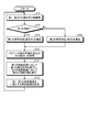
- FIG. 4 is a flowchart showing the operation of the teacher image generator 2.
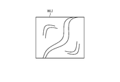
- 5 and 6 are diagrams for explaining the operation of the teacher image generator 2. Specifically, FIG. 5 is a diagram showing a first teacher image WLI in one frame after the first image processing is executed.
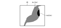
- FIG. 6 is a diagram showing a second teacher image IR of one frame after the second image processing is executed.
- the second teacher image IR shown in FIG. 6 is represented in gray scale, and the intensity (corresponding to the brightness value) of the fluorescent component imaged as it approaches black is higher (the brightness value is higher). It is a thing.
- control unit 284 executes time-division driving of the first and second light sources 221,222 (step S1A). Specifically, in step S1A, the control unit 284 receives normal light (white light) from the first light source 221 in the first period of the first and second periods that are alternately repeated based on the synchronization signal. Is emitted, and in the second period, near-infrared excitation light is emitted from the second light source 222.
- normal light white light
- Step S1A the control unit 284 synchronizes with the light emission timings of the first and second light sources 221,222 based on the synchronization signal, and causes the image sensor 242b to perform the first and second in the first and second periods.
- Step S1B to S1D That is, when the image sensor 242b is in the first period (step S1B: Yes), in other words, when the living body is irradiated with normal light (white light), the first subject image (normal light) Is imaged to generate a first teacher image (step S1C).
- the image sensor 242b captures a second subject image (fluorescence) in the second period (step S1B: No), in other words, when the living body is irradiated with near-infrared excitation light.
- a second teacher image step S1D.
- the memory controller 283a controls writing and reading of the teacher image to the memory 282 based on the synchronization signal (step S1E).
- the first and second image processing units 283b and 283c execute the following processes (step S1F). That is, the first image processing unit 283b sequentially executes the first image processing on each of the first teacher images read out from the memory 282 by the memory controller 283a. Then, the first image processing unit 283b outputs, for example, the first teacher image WLI shown in FIG.
- the second image processing unit 283c sequentially executes the second image processing on each of the second teacher images read out from the memory 282 by the memory controller 283a.
- the second image processing unit 283c outputs, for example, the second teacher image IR shown in FIG. Since the first and second teacher images are images captured by the same image sensor 242b, the first and second teacher images WLI and IR shown in FIGS. 5 and 6 are compared. As you can see, they have the same image size. That is, in the first and second teacher images, the same pixel position is a pixel that captures the same position in the same subject.
- step S1F the control unit 284 controls the operation of the third communication unit 288, and the first and second image processing units 283b and 283c output from the first and second image processing units 283b and 283c in the step S1F, respectively.
- the teacher images including the teacher images as a set are sequentially transmitted to the learning device 3 (step S1G). After this, the control unit 284 returns to step S1A.
- FIG. 7 is a diagram showing the configuration of the learning device 3.
- the learning device 3 is, for example, a server device, and is a part that generates a learning model using the teacher image generated by the teacher image generation device 2.
- the learning device 3 includes a communication unit 31, a control unit 32, and a storage unit 33.
- the communication unit 31 transmits and receives information to and from the teacher image generator 2 (third communication unit 288) via the network NE under the control of the control unit 32.
- the control unit 32 is configured by using, for example, a CPU, an FPGA, or the like, and controls the operation of the entire learning device 3.
- the control unit 32 includes a teacher image acquisition unit 321, a singular region identification unit 322, a first feature amount extraction unit 323, and a singular correspondence area learning unit 324.
- the functions of the teacher image acquisition unit 321, the singular area identification unit 322, the first feature amount extraction unit 323, and the singular correspondence area learning unit 324 will be described in "4. Operation of the learning device" described later.
- the storage unit 33 stores a program executed by the control unit 32, information necessary for the processing of the control unit 32, information generated by the processing, and the like.
- FIG. 8 is a flowchart showing the operation of the learning device 3.
- the teacher image acquisition unit 321 sequentially acquires teacher images (first and second teacher images) transmitted from the teacher image generation device 2 (third communication unit 288) via the communication unit 31. (Step S2A).
- the singular region identification unit 322 identifies the fluorescence region (singular region) in the second teacher image (step S2B). Specifically, the singular region specifying unit 322 specifies a region in which the pixel level is equal to or higher than a specific threshold value as a fluorescence region in the second teacher image.
- a luminance value or an RGB value (pixel value) corresponding to a Y signal (luminance signal) can be exemplified.
- the luminance value is adopted as the pixel level. That is, in the second teacher image IR shown in FIG. 6, the region Ar whose brightness value is equal to or higher than a specific threshold value is specified as the fluorescence region.
- the singular region specifying unit 322 has a first fluorescent region (first singular region) Ar1 (gray shown in FIG. 6) in which the brightness value is within the first range as the fluorescent region Ar.
- the second fluorescent region (second singular region) Ar2 black portion shown in FIG. 6), which is within the second range where the brightness value is higher than the first range, is specified. do.
- the first feature amount extraction unit 323 performs a fluorescence-corresponding region (specific correspondence region) in the first teacher image which is paired with the second teacher image whose fluorescence region is specified in step S2B.
- the feature quantities of the non-corresponding region and the non-corresponding region are extracted (step S2C).
- the fluorescence-corresponding region is a region of a pixel position (the same pixel position as the fluorescence region) corresponding to the fluorescence region of the second teacher image in the first teacher image.
- the non-corresponding region is a region other than the fluorescence-corresponding region in the first teacher image.
- the fluorescence-corresponding region includes the first fluorescence-corresponding region at the pixel position corresponding to the first fluorescence region Ar1 of the second teacher image and the second teacher image in the first teacher image. It is composed of a second fluorescence-corresponding region at a pixel position corresponding to the second fluorescence region Ar2 of the above. That is, the first feature amount extraction unit 323 extracts the feature amounts of the first and second fluorescence-corresponding regions and the non-fluorescence-corresponding regions, respectively.
- the following extraction methods (1) to (3) can be exemplified.
- (1) The feature amount is extracted for each pixel constituting the first fluorescence-corresponding region.
- (2) A plurality of pixels constituting the first fluorescence-corresponding region are grouped into one group, and the feature amount is extracted for each group.
- (3) The feature amount of the entire first fluorescence-corresponding region is extracted.
- the method for extracting the feature amount of the second fluorescence-corresponding region and the feature amount of the non-fluorescence-corresponding region is the same as described above.
- the feature amount a feature amount related to resolution, edge, color, brightness, noise, contrast, histogram, etc. can be exemplified.
- the specific corresponding region learning unit 324 uses the first, the first, based on the feature amount of the first fluorescence-corresponding region, the feature amount of the second fluorescence-corresponding region, and the feature amount of the non-fluorescence-corresponding region.
- a learning model is generated by machine learning the second fluorescence-corresponding region (step S2D). That is, if the learning model is used, it is possible to determine from the feature amount whether the region having the feature amount is the first or second fluorescence-corresponding region or the non-fluorescence-corresponding region.
- machine learning machine learning (deep learning) using a convolutional neural network can be exemplified.
- the learning that can accurately discriminate between the first and second fluorescence-compatible regions and the non-fluorescence-compatible regions.
- Models can be generated.
- the singular correspondence region learning unit 324 machine-learns the first and second fluorescence correspondence regions to generate a learning model
- the weights of the features related to the blue color component are weighted by other red and green. It should be lower than the weight of the feature amount related to the color component of. For example, the feature amount related to the blue color component is not used for the machine learning.
- the peculiar correspondence area learning unit 324 stores the generated learning model in the storage unit 33.
- FIG. 9 is a diagram showing the configuration of the medical observation device 4.
- FIG. 10 is a diagram showing the configuration of the camera head 44 and the control device 48.
- the medical observation device 4 has substantially the same configuration as the teacher image generation device 2.
- the same components as those in the teacher image generation device 2 are designated by the same reference numerals.
- a configuration different from that of the teacher image generation device 2 will be mainly described.
- the light source device 42 has a configuration corresponding to the light source device 22 in the teacher image generation device 2 in the medical observation device 4. As shown in FIG. 9 or 10, the light source device 42 includes only the first light source 221. That is, unlike the light source device 22, the light source device 42 does not have a second light source 222. Then, in the light source device 42, the first light source 221 is driven under the control of the control device 48, and only normal light (white light) is emitted.
- the light source device 42 is configured separately from the control device 48, but the present invention is not limited to this, and a configuration provided inside the control device 48 may be adopted.
- the camera head 44 has a configuration corresponding to the camera head 24 in the teacher image generation device 2 in the medical observation device 4. As shown in FIG. 10, the camera head 44 has a configuration in which the excitation light cut filter 242a is omitted from the camera head 24 because the light source device 42 does not have the second light source 222. Then, the camera head 44 (image sensor 242b) performs imaging at a specific frame cycle under the control of the control device 48. In the following, in order to distinguish from the first teacher image, an image generated by capturing the first subject image (normal light) with the camera head 44 (image sensor 242b) will be referred to as an captured image.
- the control device 48 corresponds to the medical image processing device according to the present disclosure.
- the control device 48 has a configuration corresponding to the control device 28 in the teacher image generation device 2 in the medical observation device 4.
- an image generation unit 483 and a control unit 484 are adopted for the control device 28 instead of the image generation unit 283 and the control unit 284.
- the image generation unit 483 is sequentially output from the camera head 44 (first communication unit 243) under the control of the control unit 484, and the captured image (RAW signal (digital signal)) received by the second communication unit 281. ) Is processed.
- FIG. 10 As shown in FIG.
- the image generation unit 483 includes a memory controller 483a, an image processing unit 483b, a second feature amount extraction unit 483c, a specific correspondence region identification unit 483d, and a display control unit 483e. ..
- the functions of the memory controller 483a, the image processing unit 483b, the second feature amount extraction unit 483c, the specific correspondence area identification unit 483d, and the display control unit 483e will be described in "6. Operation of the medical observation device" described later. explain.
- the control unit 484 is configured by using, for example, a CPU, an FPGA, or the like, and outputs a control signal via the first to third transmission cables 25, 27, 29 to output the light source device 42, the camera head 44, and the control unit 484. It controls the operation of the display device 26 and controls the operation of the entire control device 48. A part of the functions of the control unit 484 will be described in "6. Operation of the medical observation device" described later.
- FIG. 11 is a flowchart showing the operation of the medical observation device 4.
- FIG. 12 is a diagram illustrating the operation of the medical observation device 4. Specifically, FIG. 12 is a diagram showing a display image WLI'generated in step S3G.
- the control unit 484 controls the operation of the third communication unit 288, receives the learning model from the learning device 3, and uses the learning model. It is assumed that it is stored in the storage unit 287.
- the control unit 484 drives the light source device 42 (first light source 221) (step S3A). As a result, normal light (white light) is irradiated to the living body (observation target).
- the control unit 484 causes the image sensor 242b to image the first subject image (normal light) at a specific frame cycle, and generates an captured image (step S3B).
- the memory controller 483a controls writing and reading of the captured image to the memory 282 (step S3C). Specifically, the memory controller 483a sequentially outputs images from the camera head 44 (first communication unit 243) and sequentially writes the captured images received by the second communication unit 281 into the memory 282. Further, the memory controller 483a reads the captured image from the memory 282 at a specific timing, and causes the image processing unit 483b to input the read captured image.
- the image processing unit 483b sequentially executes the first image processing described above for each captured image read from the memory 282 by the memory controller 483a (step S3D).
- the second feature amount extraction unit 483c extracts the feature amount for each region of the captured image from the captured images sequentially output from the image processing unit 483b in the step S3D (step S3E). ..
- the feature amount the following extraction methods (4) and (5) can be exemplified.
- the feature amount is extracted for each pixel constituting the captured image.
- a plurality of pixels constituting the captured image are grouped into one group (region), and the feature amount is extracted for each group.
- the feature amount extracted by the second feature amount extraction unit 483c is the same type of feature amount as the feature amount extracted by the first feature amount extraction unit 323.
- the specific correspondence region identification unit 483d uses the learning model stored in the storage unit 287 based on the feature amount extracted in step S3E to display the first and second fluorescence in the captured image.
- the corresponding area is specified (step S3F).
- the display control unit 483e generates a display image in the captured image in which the first and second fluorescence-corresponding regions specified in step S3F are distinguished from other regions and displayed (step). S3G). For example, assuming that the same captured image as the first teacher image WLI shown in FIG. 5 is generated in step S3B, as shown in FIG. 12, in the captured image, the first and second images are generated.
- a display image WLI'that distinguishes the fluorescence-corresponding regions Ar1'and Ar2'(fluorescence-corresponding regions Ar') from other regions is generated.
- the identification method it is possible to exemplify the addition of a single color (for example, green or the like) to the fluorescence-corresponding region Ar'in the captured image.
- the second fluorescence region Ar2 is a region having a higher luminance value than the first fluorescence region Ar1 as described above. Therefore, the second fluorescence-corresponding region Ar2'(expressed in black for convenience of explanation in FIG. 12) is colored darker than the first fluorescence-corresponding region Ar1'(indicated in gray for convenience of explanation in FIG. 12). Is preferable.
- the display control unit 483e generates a video signal corresponding to the display image WLI'and outputs the video signal to the display device 26 via the second transmission cable 27. As a result, the display device 26 displays the display image WLI'.
- the learning device 3 uses a teacher image including the first and second teacher images as a set, and the pixel position corresponding to the fluorescent region in the second teacher image in the first teacher image.
- a learning model is generated by machine learning the fluorescence-corresponding region based on the feature amount of the fluorescence-corresponding region.
- the control device 48 acquires an captured image obtained by capturing a first subject image (normal light) from the living body (observation target), and obtains a feature amount for each region in the captured image. Based on this, the fluorescence-corresponding region in the captured image is specified using the learning model described above.
- the fluorescent region can be estimated by using the learning model, it is not necessary to administer a fluorescent substance such as indocyanine green in vivo. Therefore, convenience can be improved. Further, in the medical observation device 4, since it is not necessary to irradiate the living body with near-infrared excitation light, the second light source 222 and the excitation light cut filter 242a can be omitted, and the configuration can be simplified and downsized. Can be planned.
- the fluorescence region is divided into two stages of a first and a second fluorescence region according to the height of the brightness value.
- the weight of the feature amount related to the blue color component is made lower than the weight of the feature amount related to the other color component.
- the feature amount related to the blue color component is not used for the machine learning. Therefore, machine learning can be performed without considering unnecessary features, so that the processing load can be reduced.
- the fluorescence region is divided into two stages of the first and second fluorescence regions according to the height of the brightness value, but the present invention is not limited to this, and the fluorescence region may be only one. Alternatively, it may be divided into three or more stages according to the height of the brightness value. The same applies to the fluorescence-corresponding region corresponding to the fluorescence region.
- the light in the first wavelength band is used as normal light (white light), and the light in the second wavelength band is used as near-infrared excitation light, but the present invention is not limited to this. If the first wavelength band and the second wavelength band are different, other light may be adopted. At this time, the first and second wavelength bands may be partially overlapped bands or may be completely non-overlapping bands. For example, as the light in the second wavelength band, narrow band light used in so-called NBI (Narrow Band Imaging) may be adopted. At this time, the light in the first wavelength band may be normal light (white light) or other light.
- NBI Near Band Imaging
- photodynamic diagnosis which is one of the cancer diagnostic methods for detecting cancer cells.
- a photosensitizer such as 5-aminolevulinic acid (hereinafter referred to as 5-ALA) is used.
- 5-ALA is a natural amino acid originally contained in the living body of animals and plants.
- This 5-ALA is taken up into cells after administration into the body and biosynthesized into protoporphyrin in mitochondria. Then, in cancer cells, the protoporphyrin is excessively accumulated.
- protoporphyrins that excessively accumulate in the cancer cells have photoactivity.
- the protoporphyrin when excited with excitation light (for example, blue visible light in the wavelength band of 375 nm to 445 nm), it emits fluorescence (for example, red fluorescence in the wavelength band of 600 nm to 740 nm).
- excitation light for example, blue visible light in the wavelength band of 375 nm to 445 nm
- fluorescence for example, red fluorescence in the wavelength band of 600 nm to 740 nm.
- a cancer diagnostic method in which a light-sensitive substance is used to fluoresce cancer cells in this way is called photodynamic diagnosis.
- excitation light that excites protoporphyrin for example, blue visible light in the wavelength band of 375 nm to 445 nm
- the light in the first wavelength band may be normal light (white light) or other light.
- the first and second teacher images are generated by the single image sensor 242b, but the present invention is not limited to this.
- a configuration is adopted in which the first subject image and the second subject image are separated, imaged by two image sensors, and the first and second teacher images are generated by the two image sensors. It doesn't matter.
- the learning device 3 needs to recognize the correspondence relationship of the pixels between the first and second teacher images.
- the teacher image generation device 2 and the learning device 3 are connected to each other so as to be able to communicate with each other via the network NE, but the present invention is not limited to this, and the teacher image generation device 2 and the learning device 3 are connected. It may be configured as one device.
- the medical image processing device according to the present disclosure is mounted on the medical observation device 4 in which the insertion portion 21 is composed of a rigid endoscope, but the present invention is not limited to this.
- the medical image processing device according to the present disclosure may be mounted on a medical observation device in which the insertion portion 21 is composed of a flexible endoscope.
- the present disclosure is made in a medical observation device such as a surgical microscope (see, for example, Japanese Patent Application Laid-Open No. 2016-42881) for magnifying and observing a predetermined visual field region in the subject (in-vivo) or on the surface of the subject (surface of the living body).
- the medical image processing apparatus according to the above may be installed.
- a part of the camera head 44 and a part of the control device 48 may be provided in the connector CN1 or the connector CN2, for example.
- the following configurations also belong to the technical scope of the present disclosure.
- the first teacher image obtained by capturing the light from the subject irradiated with the light of the first wavelength band and the light of the second wavelength band different from the first wavelength band are irradiated.
- a teacher image acquisition unit that acquires a teacher image that includes a second teacher image that captures light from a subject, a singular region identification unit that specifies a singular region in the second teacher image, and the above.
- the first feature amount extraction unit that extracts the feature amount of the peculiar corresponding area of the pixel position corresponding to the peculiar area in the first teacher image and the peculiar corresponding area are machine-learned based on the feature amount.
- a learning device including a peculiar correspondence area learning unit that generates a learning model.
- the subject is a subject that fluoresces when irradiated with excitation light in the second wavelength band, and the second teacher image is from the subject irradiated with the excitation light.
- This is an image obtained by imaging the fluorescence of the above, and the specific region specifying portion specifies a region in the second teacher image in which the intensity of the fluorescent component is equal to or higher than a specific threshold value as the specific region (1).
- the learning device described in. (3) The learning device according to (1) or (2) above, wherein the singular region specifying unit specifies a region in which the pixel level is equal to or higher than a specific threshold value as the singular region in the second teacher image.
- the singular region specifying portion is, as the singular region, a first singular region in which the pixel level is within the first range and a second range in which the pixel level is higher than the first range.
- Each of the second singular regions is specified, and the first feature amount extraction unit is a first pixel position corresponding to the first singular region, which is the singular corresponding region in the first teacher image.
- the feature quantities of the peculiar correspondence region and the second peculiar correspondence region of the pixel position corresponding to the second peculiar region, which is the peculiar correspondence region in the first teacher image, are extracted, respectively, and the peculiar correspondence region is extracted.
- the learning device according to (3) wherein the learning unit machine-learns the first peculiar correspondence region and the second peculiar correspondence region based on the feature amount.
- the feature amount includes a feature amount relating to at least one of color and brightness, and when the specific correspondence region learning unit machine-learns the specific correspondence region to generate a learning model, the feature amount relates to a blue color component.
- the learning device according to any one of (1) to (4) above, wherein the weight of the feature amount is lower than the weight of the feature amount related to other color components.
- the light in the first wavelength band is the light emitted in the first period in the first period and the second period which are alternately repeated, and the light in the second wavelength band is the light emitted.
- the learning device according to any one of (1) to (5) above, which is the light emitted during the second period.
- An image capture image acquisition unit that acquires an image captured by capturing light from an observation target irradiated with light in the first wavelength band, and a second feature amount that extracts a feature amount for each region of the captured image.
- the learning model includes a extraction unit and a specific correspondence region identification unit that specifies a specific correspondence region in the captured image by using a learning model constructed by machine learning based on the feature amount, and the learning model is the first.
- the first teacher image obtained by capturing the light from the subject irradiated with the light of the wavelength band and the light from the subject irradiated with the light of the second wavelength band different from the first wavelength band.
- a teacher image that is a set of the captured second teacher image
- the feature amount of the peculiar corresponding region at the pixel position corresponding to the peculiar region in the second teacher image in the first teacher image is used.
- a medical image processing device that is a learning model generated by machine learning the singular correspondence region.
- the subject is a subject that fluoresces when irradiated with excitation light in the second wavelength band, and the second teacher image is from the subject irradiated with the excitation light.
- the medical image processing according to (7) above, which is an image obtained by imaging the fluorescence of the above, and the specific region is a region in the second teacher image in which the intensity of the fluorescence component is equal to or higher than a specific threshold value.
- the medical image processing apparatus according to (7) or (8) above, wherein the singular region is a region in which the pixel level is equal to or higher than a specific threshold value in the second teacher image.
- the singular region includes a first singular region in which the pixel level is within the first range and a second singular region in which the pixel level is within the second range higher than the first range.
- the learning model includes a first singular correspondence region of a pixel position corresponding to the first singular region, which is the singular correspondence region in the first teacher image, and the singular correspondence region in the first teacher image.
- the first singular correspondence region and the second singular correspondence region are each machined based on the feature amount of the pixel position corresponding to the second singular correspondence region, which is the singular correspondence region, with the second singular correspondence region.
- the medical image processing apparatus which is a learning model generated by learning.
- the feature amount includes a feature amount related to at least one of color and brightness, and the learning model is a state in which the weight of the feature amount related to the blue color component is lowered and the weight of the feature amount related to the other color component is lowered.
- the medical image processing apparatus according to any one of (7) to (10), which is a learning model generated by machine learning the peculiar correspondence region.
- the light in the first wavelength band is the light emitted in the first period in the first period and the second period which are alternately repeated, and the light in the second wavelength band is the light emitted.
- the medical image processing apparatus according to any one of (7) to (11), which is the light emitted during the second period.
Landscapes
- Health & Medical Sciences (AREA)
- Life Sciences & Earth Sciences (AREA)
- Surgery (AREA)
- Engineering & Computer Science (AREA)
- Medical Informatics (AREA)
- Biomedical Technology (AREA)
- Animal Behavior & Ethology (AREA)
- Radiology & Medical Imaging (AREA)
- Optics & Photonics (AREA)
- Nuclear Medicine, Radiotherapy & Molecular Imaging (AREA)
- Physics & Mathematics (AREA)
- Heart & Thoracic Surgery (AREA)
- Biophysics (AREA)
- Molecular Biology (AREA)
- Pathology (AREA)
- General Health & Medical Sciences (AREA)
- Public Health (AREA)
- Veterinary Medicine (AREA)
- Signal Processing (AREA)
- Artificial Intelligence (AREA)
- Evolutionary Computation (AREA)
- Endoscopes (AREA)
- Investigating, Analyzing Materials By Fluorescence Or Luminescence (AREA)
Priority Applications (4)
| Application Number | Priority Date | Filing Date | Title |
|---|---|---|---|
| EP21757983.8A EP4088642A4 (en) | 2020-02-18 | 2021-02-09 | LEARNING DEVICE AND MEDICAL IMAGE PROCESSING DEVICE |
| JP2022501828A JP7565331B2 (ja) | 2020-02-18 | 2021-02-09 | 学習装置及び医療用画像処理装置 |
| CN202180014096.5A CN115087386B (zh) | 2020-02-18 | 2021-02-09 | 学习装置和医疗图像处理装置 |
| US17/798,570 US12213643B2 (en) | 2020-02-18 | 2021-02-09 | Learning device and medical image processing device |
Applications Claiming Priority (2)
| Application Number | Priority Date | Filing Date | Title |
|---|---|---|---|
| JP2020-024944 | 2020-02-18 | ||
| JP2020024944 | 2020-02-18 |
Publications (1)
| Publication Number | Publication Date |
|---|---|
| WO2021166749A1 true WO2021166749A1 (ja) | 2021-08-26 |
Family
ID=77391384
Family Applications (1)
| Application Number | Title | Priority Date | Filing Date |
|---|---|---|---|
| PCT/JP2021/004847 Ceased WO2021166749A1 (ja) | 2020-02-18 | 2021-02-09 | 学習装置及び医療用画像処理装置 |
Country Status (5)
| Country | Link |
|---|---|
| US (1) | US12213643B2 (cg-RX-API-DMAC7.html) |
| EP (1) | EP4088642A4 (cg-RX-API-DMAC7.html) |
| JP (1) | JP7565331B2 (cg-RX-API-DMAC7.html) |
| CN (1) | CN115087386B (cg-RX-API-DMAC7.html) |
| WO (1) | WO2021166749A1 (cg-RX-API-DMAC7.html) |
Cited By (1)
| Publication number | Priority date | Publication date | Assignee | Title |
|---|---|---|---|---|
| WO2025144715A1 (en) * | 2023-12-29 | 2025-07-03 | Ipg Photonics Corporation | Systems and methods for controlling laser treatments using reflected intensity signals |
Families Citing this family (1)
| Publication number | Priority date | Publication date | Assignee | Title |
|---|---|---|---|---|
| KR20240079009A (ko) * | 2022-11-28 | 2024-06-04 | 현대자동차주식회사 | 액티브 러닝 장치 및 그 방법 |
Citations (4)
| Publication number | Priority date | Publication date | Assignee | Title |
|---|---|---|---|---|
| JP2015029841A (ja) | 2013-08-06 | 2015-02-16 | 三菱電機エンジニアリング株式会社 | 撮像装置および撮像方法 |
| JP2016042981A (ja) | 2014-08-21 | 2016-04-04 | ソニー・オリンパスメディカルソリューションズ株式会社 | 医療用観察装置および医療用観察システム |
| WO2020003991A1 (ja) * | 2018-06-28 | 2020-01-02 | 富士フイルム株式会社 | 医療画像学習装置、方法及びプログラム |
| WO2020022027A1 (ja) * | 2018-07-26 | 2020-01-30 | 富士フイルム株式会社 | 学習装置及び学習方法 |
Family Cites Families (9)
| Publication number | Priority date | Publication date | Assignee | Title |
|---|---|---|---|---|
| KR101463354B1 (ko) * | 2013-10-22 | 2014-11-18 | 영남대학교 산학협력단 | 초분광 영상의 특이영역 검출 장치 및 그 방법 |
| JP6339872B2 (ja) * | 2014-06-24 | 2018-06-06 | オリンパス株式会社 | 画像処理装置、内視鏡システム及び画像処理方法 |
| JP6721994B2 (ja) * | 2015-04-30 | 2020-07-15 | ソニー・オリンパスメディカルソリューションズ株式会社 | 医療用信号処理装置および医療用観察システム |
| EP3176751B1 (en) * | 2015-12-01 | 2020-12-30 | Ricoh Company, Ltd. | Information processing device, information processing method, computer-readable recording medium, and inspection system |
| TW201902411A (zh) * | 2017-06-09 | 2019-01-16 | 多田智裕 | 藉由消化器官之內視鏡影像之疾病的診斷支援方法、診斷支援系統、診斷支援程式及記憶此診斷支援程式之電腦可讀取之記錄媒體 |
| WO2019230302A1 (ja) * | 2018-05-28 | 2019-12-05 | 富士フイルム株式会社 | 学習データ収集装置、学習データ収集方法及びプログラム、学習システム、学習済みモデル、並びに内視鏡画像処理装置 |
| JP7005767B2 (ja) * | 2018-07-20 | 2022-01-24 | 富士フイルム株式会社 | 内視鏡画像認識装置、内視鏡画像学習装置、内視鏡画像学習方法及びプログラム |
| JP6971934B2 (ja) | 2018-08-10 | 2021-11-24 | 株式会社東芝 | 画像処理装置 |
| JP7038641B2 (ja) * | 2018-11-02 | 2022-03-18 | 富士フイルム株式会社 | 医療診断支援装置、内視鏡システム、及び作動方法 |
-
2021
- 2021-02-09 US US17/798,570 patent/US12213643B2/en active Active
- 2021-02-09 EP EP21757983.8A patent/EP4088642A4/en active Pending
- 2021-02-09 CN CN202180014096.5A patent/CN115087386B/zh active Active
- 2021-02-09 JP JP2022501828A patent/JP7565331B2/ja active Active
- 2021-02-09 WO PCT/JP2021/004847 patent/WO2021166749A1/ja not_active Ceased
Patent Citations (4)
| Publication number | Priority date | Publication date | Assignee | Title |
|---|---|---|---|---|
| JP2015029841A (ja) | 2013-08-06 | 2015-02-16 | 三菱電機エンジニアリング株式会社 | 撮像装置および撮像方法 |
| JP2016042981A (ja) | 2014-08-21 | 2016-04-04 | ソニー・オリンパスメディカルソリューションズ株式会社 | 医療用観察装置および医療用観察システム |
| WO2020003991A1 (ja) * | 2018-06-28 | 2020-01-02 | 富士フイルム株式会社 | 医療画像学習装置、方法及びプログラム |
| WO2020022027A1 (ja) * | 2018-07-26 | 2020-01-30 | 富士フイルム株式会社 | 学習装置及び学習方法 |
Non-Patent Citations (2)
| Title |
|---|
| OTA, YUDAI ET AL.: "Extraction of tongue coating by machine learning using texture and color information", PROCEEDINGS OF THE JAMIT ANNUAL MEETING - DAI 36KAI NIHON IYŌ GAZŌ KOGAKKAI TAIKAI : KAIKI : 2017NEN 7GATSU 17NICHI (MOKU)-23NICHI (DO), KAIJŌ: JŪROKU PURAZA, GAKKAI CHŌ: FUJITA HIROSHI (GIFU DAIGAKU) / SHUSAI: NIHON IYŌ GAZŌ KŌGAKKAI, KYOSAI: GIFU D, 27 July 2017 (2017-07-27), pages 332 - 335, XP009530616 * |
| See also references of EP4088642A4 |
Cited By (1)
| Publication number | Priority date | Publication date | Assignee | Title |
|---|---|---|---|---|
| WO2025144715A1 (en) * | 2023-12-29 | 2025-07-03 | Ipg Photonics Corporation | Systems and methods for controlling laser treatments using reflected intensity signals |
Also Published As
| Publication number | Publication date |
|---|---|
| US12213643B2 (en) | 2025-02-04 |
| EP4088642A1 (en) | 2022-11-16 |
| JP7565331B2 (ja) | 2024-10-10 |
| JPWO2021166749A1 (cg-RX-API-DMAC7.html) | 2021-08-26 |
| EP4088642A4 (en) | 2023-06-07 |
| US20230112628A1 (en) | 2023-04-13 |
| CN115087386A (zh) | 2022-09-20 |
| CN115087386B (zh) | 2025-04-25 |
Similar Documents
| Publication | Publication Date | Title |
|---|---|---|
| US11463668B2 (en) | Medical image processing device, medical observation system, and image processing method | |
| US11948080B2 (en) | Image processing method and image processing apparatus | |
| JP7449736B2 (ja) | 医療用画像処理装置及び医療用観察システム | |
| WO2019220848A1 (ja) | 内視鏡装置、内視鏡操作方法、及びプログラム | |
| WO2020008834A1 (ja) | 画像処理装置、方法及び内視鏡システム | |
| CN103124515A (zh) | 摄像装置 | |
| US20240306883A1 (en) | Medical image processing apparatus and medical observation system | |
| US20250387053A1 (en) | Medical light source device and medical observation system | |
| JP7565331B2 (ja) | 学習装置及び医療用画像処理装置 | |
| CN112991367A (zh) | 成像系统及生成可见光视频和彩色光视频的方法 | |
| US12295553B2 (en) | Medical image processing apparatus and medical observation system | |
| JP7551465B2 (ja) | 医療用画像処理装置及び医療用観察システム | |
| JP7281308B2 (ja) | 医療用画像処理装置及び医療用観察システム | |
| JP2025028292A (ja) | 医療用観察システム、医療用光源制御装置、及び医療用光源制御方法 | |
| JP2021132812A (ja) | 医療用画像処理装置及び医療用観察システム | |
| JP2021027867A (ja) | ファイリング装置、ファイリング方法及びプログラム | |
| JP2021146198A (ja) | 医療用画像処理装置及び医療用観察システム | |
| JP2021003347A (ja) | 医療用画像処理装置及び医療用観察システム | |
| JP7224963B2 (ja) | 医療用制御装置及び医療用観察システム | |
| JP2022082298A (ja) | 医療用制御装置及び医療用観察システム | |
| JP5224390B2 (ja) | 内視鏡装置および内視鏡装置の作動方法 | |
| US10918269B2 (en) | Medical light source apparatus and medical observation system | |
| WO2024166306A1 (ja) | 医療用装置、内視鏡システム、制御方法、制御プログラム、及び学習装置 |
Legal Events
| Date | Code | Title | Description |
|---|---|---|---|
| 121 | Ep: the epo has been informed by wipo that ep was designated in this application |
Ref document number: 21757983 Country of ref document: EP Kind code of ref document: A1 |
|
| ENP | Entry into the national phase |
Ref document number: 2022501828 Country of ref document: JP Kind code of ref document: A |
|
| ENP | Entry into the national phase |
Ref document number: 2021757983 Country of ref document: EP Effective date: 20220809 |
|
| NENP | Non-entry into the national phase |
Ref country code: DE |
|
| WWG | Wipo information: grant in national office |
Ref document number: 202180014096.5 Country of ref document: CN |