WO2021166169A1 - 車両状態推定方法、車両状態推定装置、及び車両状態推定プログラム - Google Patents
車両状態推定方法、車両状態推定装置、及び車両状態推定プログラム Download PDFInfo
- Publication number
- WO2021166169A1 WO2021166169A1 PCT/JP2020/006829 JP2020006829W WO2021166169A1 WO 2021166169 A1 WO2021166169 A1 WO 2021166169A1 JP 2020006829 W JP2020006829 W JP 2020006829W WO 2021166169 A1 WO2021166169 A1 WO 2021166169A1
- Authority
- WO
- WIPO (PCT)
- Prior art keywords
- vehicle
- estimated
- lane
- image
- state estimation
- Prior art date
- Legal status (The legal status is an assumption and is not a legal conclusion. Google has not performed a legal analysis and makes no representation as to the accuracy of the status listed.)
- Ceased
Links
Images









Classifications
-
- G—PHYSICS
- G06—COMPUTING OR CALCULATING; COUNTING
- G06V—IMAGE OR VIDEO RECOGNITION OR UNDERSTANDING
- G06V20/00—Scenes; Scene-specific elements
- G06V20/50—Context or environment of the image
- G06V20/56—Context or environment of the image exterior to a vehicle by using sensors mounted on the vehicle
- G06V20/588—Recognition of the road, e.g. of lane markings; Recognition of the vehicle driving pattern in relation to the road
-
- B—PERFORMING OPERATIONS; TRANSPORTING
- B60—VEHICLES IN GENERAL
- B60W—CONJOINT CONTROL OF VEHICLE SUB-UNITS OF DIFFERENT TYPE OR DIFFERENT FUNCTION; CONTROL SYSTEMS SPECIALLY ADAPTED FOR HYBRID VEHICLES; ROAD VEHICLE DRIVE CONTROL SYSTEMS FOR PURPOSES NOT RELATED TO THE CONTROL OF A PARTICULAR SUB-UNIT
- B60W40/00—Estimation or calculation of non-directly measurable driving parameters for road vehicle drive control systems not related to the control of a particular sub unit, e.g. by using mathematical models
- B60W40/02—Estimation or calculation of non-directly measurable driving parameters for road vehicle drive control systems not related to the control of a particular sub unit, e.g. by using mathematical models related to ambient conditions
-
- B—PERFORMING OPERATIONS; TRANSPORTING
- B60—VEHICLES IN GENERAL
- B60W—CONJOINT CONTROL OF VEHICLE SUB-UNITS OF DIFFERENT TYPE OR DIFFERENT FUNCTION; CONTROL SYSTEMS SPECIALLY ADAPTED FOR HYBRID VEHICLES; ROAD VEHICLE DRIVE CONTROL SYSTEMS FOR PURPOSES NOT RELATED TO THE CONTROL OF A PARTICULAR SUB-UNIT
- B60W40/00—Estimation or calculation of non-directly measurable driving parameters for road vehicle drive control systems not related to the control of a particular sub unit, e.g. by using mathematical models
- B60W40/02—Estimation or calculation of non-directly measurable driving parameters for road vehicle drive control systems not related to the control of a particular sub unit, e.g. by using mathematical models related to ambient conditions
- B60W40/04—Traffic conditions
-
- B—PERFORMING OPERATIONS; TRANSPORTING
- B60—VEHICLES IN GENERAL
- B60W—CONJOINT CONTROL OF VEHICLE SUB-UNITS OF DIFFERENT TYPE OR DIFFERENT FUNCTION; CONTROL SYSTEMS SPECIALLY ADAPTED FOR HYBRID VEHICLES; ROAD VEHICLE DRIVE CONTROL SYSTEMS FOR PURPOSES NOT RELATED TO THE CONTROL OF A PARTICULAR SUB-UNIT
- B60W40/00—Estimation or calculation of non-directly measurable driving parameters for road vehicle drive control systems not related to the control of a particular sub unit, e.g. by using mathematical models
- B60W40/10—Estimation or calculation of non-directly measurable driving parameters for road vehicle drive control systems not related to the control of a particular sub unit, e.g. by using mathematical models related to vehicle motion
-
- B—PERFORMING OPERATIONS; TRANSPORTING
- B60—VEHICLES IN GENERAL
- B60W—CONJOINT CONTROL OF VEHICLE SUB-UNITS OF DIFFERENT TYPE OR DIFFERENT FUNCTION; CONTROL SYSTEMS SPECIALLY ADAPTED FOR HYBRID VEHICLES; ROAD VEHICLE DRIVE CONTROL SYSTEMS FOR PURPOSES NOT RELATED TO THE CONTROL OF A PARTICULAR SUB-UNIT
- B60W40/00—Estimation or calculation of non-directly measurable driving parameters for road vehicle drive control systems not related to the control of a particular sub unit, e.g. by using mathematical models
- B60W40/10—Estimation or calculation of non-directly measurable driving parameters for road vehicle drive control systems not related to the control of a particular sub unit, e.g. by using mathematical models related to vehicle motion
- B60W40/105—Speed
-
- G—PHYSICS
- G06—COMPUTING OR CALCULATING; COUNTING
- G06V—IMAGE OR VIDEO RECOGNITION OR UNDERSTANDING
- G06V20/00—Scenes; Scene-specific elements
- G06V20/50—Context or environment of the image
- G06V20/56—Context or environment of the image exterior to a vehicle by using sensors mounted on the vehicle
- G06V20/58—Recognition of moving objects or obstacles, e.g. vehicles or pedestrians; Recognition of traffic objects, e.g. traffic signs, traffic lights or roads
-
- B—PERFORMING OPERATIONS; TRANSPORTING
- B60—VEHICLES IN GENERAL
- B60W—CONJOINT CONTROL OF VEHICLE SUB-UNITS OF DIFFERENT TYPE OR DIFFERENT FUNCTION; CONTROL SYSTEMS SPECIALLY ADAPTED FOR HYBRID VEHICLES; ROAD VEHICLE DRIVE CONTROL SYSTEMS FOR PURPOSES NOT RELATED TO THE CONTROL OF A PARTICULAR SUB-UNIT
- B60W2420/00—Indexing codes relating to the type of sensors based on the principle of their operation
- B60W2420/40—Photo, light or radio wave sensitive means, e.g. infrared sensors
- B60W2420/403—Image sensing, e.g. optical camera
-
- B—PERFORMING OPERATIONS; TRANSPORTING
- B60—VEHICLES IN GENERAL
- B60W—CONJOINT CONTROL OF VEHICLE SUB-UNITS OF DIFFERENT TYPE OR DIFFERENT FUNCTION; CONTROL SYSTEMS SPECIALLY ADAPTED FOR HYBRID VEHICLES; ROAD VEHICLE DRIVE CONTROL SYSTEMS FOR PURPOSES NOT RELATED TO THE CONTROL OF A PARTICULAR SUB-UNIT
- B60W2552/00—Input parameters relating to infrastructure
- B60W2552/53—Road markings, e.g. lane marker or crosswalk
-
- B—PERFORMING OPERATIONS; TRANSPORTING
- B60—VEHICLES IN GENERAL
- B60W—CONJOINT CONTROL OF VEHICLE SUB-UNITS OF DIFFERENT TYPE OR DIFFERENT FUNCTION; CONTROL SYSTEMS SPECIALLY ADAPTED FOR HYBRID VEHICLES; ROAD VEHICLE DRIVE CONTROL SYSTEMS FOR PURPOSES NOT RELATED TO THE CONTROL OF A PARTICULAR SUB-UNIT
- B60W2554/00—Input parameters relating to objects
- B60W2554/80—Spatial relation or speed relative to objects
Definitions
- the disclosed technology relates to a vehicle state estimation method, a vehicle state estimation device, and a vehicle state estimation program.
- Non-Patent Document 1 reports on a technique relating to driving control or driving support of an automobile.
- the state of the other vehicle such as which lane the vehicle other than the own vehicle (hereinafter referred to as the other vehicle) is traveling at what speed and in which direction, and the information of the other vehicle are integrated into the lane.
- Accurately recognizing each traffic flow is extremely important for safely controlling the running of the own vehicle.
- the disclosed technology was made in view of the above points, and is a vehicle state estimation method and a vehicle that enable the relationship between the own vehicle and another vehicle and the state of the other vehicle to be estimated without using special equipment. It is an object of the present invention to provide a state estimation device and a vehicle state estimation program.
- the first aspect of the present disclosure is a vehicle state estimation method in which an information processing device including a processor and a memory connected to the processor estimates the position or state of a vehicle, and an image including an image to be estimated is displayed. Using a line segment connecting at least two points selected from the region in which the vehicle to be estimated is captured in the image, the estimation target is based on the image pickup device that captured the image. Estimate the position or condition of the vehicle.
- a second aspect of the present disclosure is a vehicle state estimation device that estimates the position or state of a vehicle, wherein an image acquisition unit that acquires an image including the vehicle to be estimated and the vehicle to be estimated in the image are Another vehicle state estimation unit that estimates the position or state of the target vehicle to be estimated based on the image pickup device that captured the image using a line segment connecting at least two points selected from the imaged region. And.
- a third aspect of the present disclosure is a vehicle state estimation program that causes a computer to estimate the position or state of a vehicle, and obtains an image including the vehicle to be estimated by the computer, and the vehicle to be estimated in the image. Using a line segment connecting at least two points selected from the region in which the image is imaged, a process of estimating the position or state of the vehicle to be estimated is executed based on the image pickup device that captured the image. ..
- a vehicle state estimation device by analyzing an image including the vehicle to be estimated taken from a known position, the state of the other vehicle without obtaining information from the other vehicle and without using special equipment.
- a vehicle state estimation device by analyzing an image including the vehicle to be estimated taken from a known position, the state of the other vehicle without obtaining information from the other vehicle and without using special equipment.
- a vehicle state estimation device by analyzing an image including the vehicle to be estimated taken from a known position, the state of the other vehicle without obtaining information from the other vehicle and without using special equipment.
- the former relationship includes the position of the second vehicle with respect to the first vehicle, the traveling direction of the second vehicle with respect to the traveling direction of the first vehicle, and the like.
- the latter relationship includes the speed of the second vehicle, the lane in which it is traveling, or the direction in which it is traveling.
- the first vehicle is assumed to be the own vehicle and the second vehicle is assumed to be another vehicle, but the disclosed technology is that both the first vehicle and the second vehicle are other vehicles. good.
- the traffic flow on the road may be estimated based on the above relationship.
- the second vehicle shown in the image taken from the first vehicle (hereinafter referred to as own vehicle) and the own vehicle are relative to each other.
- the relationship is estimated from the above image. More specifically, the relative relationship is estimated using a line segment connecting at least two arbitrary points in the region where the other vehicle is imaged in the image.
- the relative relationship obtained here may be used, for example, for controlling a vehicle in automatic driving.
- information that can be acquired by a sensor mounted on the own vehicle and information necessary for estimation from another subject captured in the above image are obtained, and the obtained information is used.
- the information that can be acquired by the sensor mounted on the own vehicle includes, for example, the position of the own vehicle obtained by GPS (Global Positioning System) or the speed obtained from the speed sensor.
- Information required for estimation obtained from other subjects captured in the above image includes, for example, a line that divides a road lane. As a more specific example, the lane in which another vehicle is traveling can be estimated by using the relative relationship with the position of the own vehicle.
- the absolute relationship thus obtained can be used for lane pricing or traffic flow estimation.
- FIG. 1A is a diagram showing a schematic configuration of a vehicle state estimation system including a vehicle state estimation device according to the present embodiment.
- the vehicle state estimation device 10 and the camera 20 are mounted on the own vehicle 1.
- the vehicle state estimation device 10 estimates the relative relationship between the own vehicle 1 and the other vehicle shown in the image captured from any position of the own vehicle 1.
- the relative relationship referred to here is the position or traveling direction of another vehicle with respect to the own vehicle 1.
- the vehicle state estimation device 10 is a device that estimates the state of the object to be estimated based on the image captured by the camera 20.
- the state in the first embodiment is the relative relationship between the other vehicle and the own vehicle 1 as described above.
- the other vehicle is an example of the subject being imaged, and the subject being imaged may be a subject existing on the road such as a manhole or a road marking.
- the relative relationship is the position or direction of travel of another vehicle with respect to the own vehicle.
- the vehicle state estimation device 10 uses image data obtained by imaging a range including a road area in the traveling direction in which the own vehicle 1 is traveling, and uses the position of the own vehicle 1 at the time when another vehicle is imaged as a reference. Estimate the condition of other vehicles. An example of the functional configuration of the vehicle state estimation device 10 will be described in detail later.
- the camera 20 is an image pickup device using a solid-state image pickup device such as a CMOS (Complementary Metal Oxide Sensor) sensor, for example.
- CMOS Complementary Metal Oxide Sensor
- the installation location, elevation angle, and azimuth angle of the camera 20 are set so that at least the road region in the traveling direction in which the own vehicle 1 is traveling is included in the imaging range. Then, the camera 20 outputs the image data obtained by imaging the range including the road region in the traveling direction of the own vehicle 1 to the vehicle state estimation device 10.
- the camera 20 may be provided exclusively for estimating the state of another vehicle by the vehicle state estimation device 10, or may use a camera mounted on the own vehicle 1 for a purpose other than estimating the state of the other vehicle. May be good.
- a camera mounted on the own vehicle 1 may be used for a purpose other than estimating the state of another vehicle, such as a drive recorder or a stereo camera for measuring the distance between vehicles.
- a camera provided on the driver's helmet or steering wheel may be used as the camera 20.
- a camera provided in a mobile terminal such as a smartphone owned by a passenger of the own vehicle 1 may be used as the camera 20.
- any installed camera may be used as the camera 20 as long as the surrounding environment of the own vehicle 1 can be imaged.
- the camera arranged in the own vehicle 1 may also capture images in any of the front, rear, and side directions.
- the camera 20 may be an infrared camera that detects infrared rays.
- the image data output by the camera 20 may be moving image data, or may be still image data captured at regular time intervals.
- an image captured by a camera installed on the roadside may be used instead of the camera 20 mounted on the own vehicle 1, an image captured by a camera installed on the roadside may be used. In this case, the vehicle state estimation device 10 estimates the relative positional relationship between the position of the camera installed on the roadside and another vehicle.
- FIG. 2 is a block diagram showing the hardware configuration of the vehicle state estimation device 10.
- the vehicle state estimation device 10 includes a CPU (Central Processing Unit) 11, a ROM (Read Only Memory) 12, a RAM (Random Access Memory) 13, a storage 14, an input unit 15, a display unit 16, and communication. It has an interface (I / F) 17.
- the configurations are connected to each other via a bus 19 so as to be communicable with each other.
- the CPU 11 is a central arithmetic processing unit that executes various programs and controls each part. That is, the CPU 11 reads the program from the ROM 12 or the storage 14, and executes the program using the RAM 13 as a work area. The CPU 11 controls each of the above configurations and performs various arithmetic processes according to the program stored in the ROM 12 or the storage 14. In the present embodiment, the ROM 12 or the storage 14 stores a vehicle state estimation program for estimating the state of another vehicle.
- the ROM 12 stores various programs and various data.
- the RAM 13 temporarily stores a program or data as a work area.
- the storage 14 is composed of a storage device such as an HDD (Hard Disk Drive) or an SSD (Solid State Drive), and stores various programs including an operating system and various data.
- the input unit 15 includes a pointing device such as a mouse and a keyboard, and is used for performing various inputs.
- the display unit 16 is, for example, a liquid crystal display and displays various types of information.
- the display unit 16 may adopt a touch panel method and function as an input unit 15.
- the communication interface 17 is an interface for communicating with other devices such as an external device, and a wireless communication standard represented by, for example, 4G, 5G, Wi-Fi (registered trademark), etc. is used.
- FIG. 3A is a block diagram showing an example of the functional configuration of the vehicle state estimation device 10.
- the vehicle state estimation device 10 has an input / output interface (I / F) 110, a storage unit 130, and another vehicle state estimation unit 140 as functional configurations.
- Each functional configuration is realized by the CPU 11 reading the vehicle state estimation program stored in the ROM 12 or the storage 14, deploying the program in the RAM 13, and executing the program.
- the input / output I / F 110 receives the image captured by the camera 20 and supplies the received data to the other vehicle state estimation unit 140. Further, the input / output I / F 110 may output data representing the estimation result of the state of the other vehicle output from the other vehicle state estimation unit 140 to an external device (not shown).
- the external device may be, for example, a display or a speaker mounted on the own vehicle 1.
- the storage unit 130 is provided in, for example, the ROM 12 or the storage 14.
- the storage unit 130 includes each vehicle state storage unit 132.
- each vehicle state storage unit 132 the relative relationship with the other vehicle based on the own vehicle 1 estimated by the other vehicle state estimation unit 144 is stored together with the time when the relationship is estimated.
- the other vehicle state estimation unit 140 estimates the relative relationship between the own vehicle 1 and the other vehicle.
- the other vehicle state estimation unit 140 includes an image acquisition unit 141, another vehicle detection unit 143, and another vehicle state estimation unit 144.
- the image acquisition unit 141 sequentially captures the image data output from the camera 20 via the input / output I / F 110.
- the image acquisition unit 141 associates the captured image data with information indicating the imaging timing or reception timing of the image data, and outputs the captured image data to the other vehicle detection unit 143.
- the image acquisition unit 141 cuts out the still image data at a predetermined frame cycle and outputs it to the lane marking detection unit 142 and the other vehicle detection unit 143. You may.
- the image acquisition unit 141 may perform a calibration process for removing noise and correcting individual differences in the performance of the camera 20 or inclination at the time of installation of the still image data.
- an image acquisition unit (not shown) is prepared outside the other vehicle state estimation unit 140, and image data is output to the other vehicle detection unit 143 from the image acquisition unit prepared externally. May be good.
- the other vehicle detection unit 143 detects an area on the image data in which the other vehicle is imaged from the image data received from the image acquisition unit 141. This area may be rectangular. When the area is a rectangle, the coordinates of the rectangle on the image data are calculated. The other vehicle detection unit 143 sends information on the coordinates of the circumscribed rectangle circumscribing the detected area on the image data of the other vehicle to the other vehicle state estimation unit 144. The other vehicle detection unit 143 may send only the coordinates of the two points forming the edge of the circumscribing rectangle to the other vehicle state estimation unit 144. The coordinates of the two points may be, for example, the coordinates of two vertices that are diagonal to the circumscribing rectangle.
- the extrinsic rectangle is the smallest rectangle that includes the entire area where the other vehicle is imaged, but it may be the smallest rectangle that substantially includes the area where the other vehicle is imaged.
- the term "included” means that the area in which the other vehicle is imaged may slightly extend from the rectangle.
- the other vehicle detection unit 143 may use the information regarding the shape of the other vehicle.
- the shape of the other vehicle may be, for example, a circumscribed hexagon relating to the shape of the other vehicle.
- the other vehicle detection unit 143 may calculate the coordinates of the pixel estimated to be the "vehicle" in the image by the semantic segmentation method, not limited to the coordinates of the vertices of the circumscribed rectangle or the circumscribed hexagon.
- the other vehicle detection unit 143 may calculate the coordinates of two points included in the ground contact surface of the tire of the other vehicle. It is preferable to calculate the coordinates of one point for each tire, but the coordinates of two points may be calculated from one tire.
- the other vehicle detection unit 143 may detect the tires, then detect the vehicle body, and classify the detected plurality of tires by the tires constituting the same vehicle by using the detected vehicle body region. ..
- the other vehicle state estimation unit 144 performs a process of estimating the relative relationship between the own vehicle 1 and the other vehicle. Specifically, the other vehicle state estimation unit 144 performs a process of estimating the other vehicle state using the coordinates of the circumscribed rectangle that circumscribes the other vehicle detected by the other vehicle detection unit 143. The specific estimation process will be described later.
- the other vehicle state estimation unit 144 uses the information related to the camera 20 that is not affected by the change in the relationship between the other vehicle to be estimated and the camera 20 to estimate, as in the third embodiment described later.
- the state of other vehicles may be estimated.
- the information related to the camera 20 may be either the position of the camera 20 or the road on which the camera 20 is located.
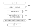
- FIG. 4A is a flowchart showing the flow of the vehicle state estimation process by the vehicle state estimation device 10.
- the vehicle state estimation process is performed by the CPU 11 reading the vehicle state estimation program from the ROM 12 or the storage 14, expanding the program into the RAM 13 and executing the program.
- the CPU 11 acquires the image data captured by the camera 20 (step S101).
- step S101 the CPU 11 estimates the relative relationship between the own vehicle and another vehicle using the image data acquired from the camera 20 (step S102). The process of step S102 will be described in detail later.
- step S102 the CPU 11 outputs the relative relationship between the own vehicle and the other vehicle to the external device (step S103).
- FIG. 5 is a diagram for showing an example in this embodiment.
- the own vehicle 1 is the second lane from the left and the other vehicle 2 is from the left on a road having two lanes on each side, a side road, and a total of four lanes for going up and down. It is assumed that you are driving in the first lane.
- Reference numeral 41 is a median strip
- reference numerals 42a to 42d are lane marking lines
- reference numeral 43 is a curb
- reference numeral 44 is a boundary between a sidewalk and a building.
- the median strip 41 is an example of a lane marking.
- FIG. 8A is a flowchart showing the details of the process shown in step S102 of FIG. 4A.
- the CPU 11 acquires image data from the camera 20 (step S121).
- the CPU 11 uses the image data acquired from the camera 20 to detect the area where the other vehicle existing in the image data is imaged (step S122), and the other vehicle existing in the image data is imaged. Clarify the area on the image data. As described above, this region may be a rectangle including other vehicles.
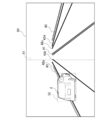
- FIG. 9A is a diagram showing an example in which a rectangle 52 including a region in which another vehicle is imaged is detected from a certain image data.
- an algorithm for detecting the subject captured in an arbitrary image may be used, or a neural network such as CNN (Convolutional Neural Network, convolutional neural network) may be used. You may use it. Specifically, it may be detected using YOLO (You Look Only Once) (see https://arxiv.org/abs/1612.08242 and the like).
- YOLO You Look Only Once
- FIG. 9A the case where one other vehicle 2 exists in the image data is illustrated, but when a plurality of other vehicles 2 are imaged, the CPU 11 determines the area where the other vehicle 2 is imaged. It is detected for each other vehicle 2.
- the CPU 11 When estimating the traveling direction of another vehicle, the CPU 11 detects a pair of front wheels and rear wheels existing on one side of the vehicle body of the other vehicle from the image data. Further, the CPU 11 obtains the coordinates on the image regarding the detected lowermost portions of the front wheels and the rear wheels.
- the coordinates related to the lowermost portion are for acquiring the ground contact points of the front wheels and the rear wheels, but may be any two points in the area where the other vehicle is imaged. The reason why the coordinates at the bottom of the front wheels and the rear wheels are preferable will be explained.
- the tires of a general automobile are in contact with the road, and the ground contact points of the front wheels and the ground contact points of the rear wheels are almost in a straight line.
- the condition that the two points should be satisfied is that the line connecting the two points is almost horizontal to the road as in the side step.
- the CPU 11 selects two points close to the ground contact surface according to the ground clearance of the imaged camera 20 and the vehicle height of the other vehicle 2, or divides the shape of the other vehicle 2 into two on the left and right. You may choose the point where you can get. In this case, if the difference between the ground clearance of the camera 20 and the vehicle height of the other vehicle 2 is equal to or greater than a predetermined threshold value, the CPU 11 can obtain a line that divides the area of the other vehicle 2 into two on the left and right.
- the horizontal relationship with respect to the road will be described with reference to FIG.
- the line segment connecting the point 62a and the point 62b on the opposite side of the ground contact surface with respect to the center of the tire has a horizontal relationship with respect to the road, and the line segment connecting the point 62a and the point 62c near the door knob is horizontal with respect to the road. It's not a relationship.
- the horizontal relationship is a line segment whose height in the real space hardly changes with respect to the lowermost surface of the car.
- FIG. 10 is a diagram showing the coordinates of the lowermost portions of the front wheels and the rear wheels existing on one side of the vehicle body of the other vehicle 2.
- the CPU 11 obtains the coordinates of the lowest portion of the rear wheels of the other vehicle 2 (x c1 , y c1 ) and the coordinates of the lowest portion of the front wheels of the other vehicle 2 (x c2 , y c2 ).
- the front wheels and the rear wheels of the other vehicle 2 may also be detected inside the circumscribed rectangle 52 of the other vehicle 2 by using an object detection algorithm such as YOLO.
- the CPU 11 obtains the coordinates of the lowermost portions of the front wheels and the rear wheels existing on one side of the vehicle body of the other vehicle 2, the CPU 11 obtains the angle formed by the line segment passing through the obtained coordinates and the horizontal line 61 in the image data 50.
- the line segment obtained here is a line segment connecting at least two points in the region where the other vehicle is imaged, for example, a line segment connecting the points forming the region where the two tires of the vehicle are in contact with the ground.
- the horizon will be described.
- the horizontal line is a virtual line segment that is not photographed, and the y coordinate is fixed when the image is regarded as an xy plane, and the line segment passes through two arbitrary x coordinate points.
- An example is shown as a horizontal line 61 in FIG. It is assumed that the camera is installed so that it is horizontal to the road, but if the camera is not horizontal to the road, the image itself will be horizontal to the road. May be corrected.
- FIG. 11 is a diagram showing an example of image data 50.
- the angle ⁇ c1 shown in FIG. 11 is an example of the angle formed by the line segment and the horizontal line 61 related to the other vehicle 2 located on the left side with respect to the own vehicle 1. That is, FIG. 11 is a diagram for explaining an angle composed of a line segment passing through the coordinates of the lowermost portions of the front wheels and the rear wheels existing on one side of the vehicle body of the other vehicle 2 and the horizontal line 61.
- the angle ⁇ c formed by the line segment 53 passing through the coordinates (x c1 , y c1 ) and (x c2 , y c2 ) and the horizontal line 61 is calculated by the following formula.
- ⁇ c arctan ⁇ (y c2- y c1 ) / (x c2- x c1 ) ⁇
- CPU11 is the size of the obtained angle phi c, can be another vehicle relative to the own vehicle 1 is what is located left or right, to estimate whether and how much apart. That is, in the CPU 11, if ⁇ c is equal to or less than the predetermined first threshold value, the other vehicle 2 is on the left side of the own vehicle 1, and if ⁇ c is equal to or more than the predetermined first threshold value, the other vehicle 2 is the own vehicle 1. It can be estimated to be located on the right side. Further, the CPU 11 may estimate the distance between the own vehicle 1 and the other vehicle 2 based on the size of the difference between the first threshold value and ⁇ c. The distance referred to here is a lateral distance with respect to the own vehicle.
- the CPU 11 increases the distance between the own vehicle 1 and the other vehicle 2 as the difference between the first threshold value and ⁇ c becomes smaller. It may be presumed that it is.
- ⁇ c is equal to or greater than the first threshold value, that is, when the other vehicle 2 is located on the right side, it is estimated that the greater the difference between the first threshold value and ⁇ c , the greater the distance between the own vehicle and the other vehicle. May be good.
- ⁇ c is an angle less than 90 degrees such as 20 degrees and 47 degrees, it may be estimated that the other vehicle 2 is located on the left side of the own vehicle 1.
- ⁇ c1 of 47 degrees is selected among the other vehicle 2 that has acquired ⁇ c2 of 20 degrees and the other vehicle that has acquired ⁇ c1 of 47 degrees. It may be estimated that the acquired other vehicle 2 is located closer to the own vehicle 1. If ⁇ c3 is 165 degrees or the like, it may be estimated that the other vehicle 2 is located on the right side of the own vehicle 1.
- the CPU 11 estimates how far the other vehicle 2 is traveling from the lane in which the own vehicle 1 is traveling, according to the estimated position of the other vehicle 2 and the distance from the own vehicle 1. May be good. As described in the second embodiment described later, when the center line of the road is known or given, the CPU 11 determines whether the other vehicle 2 is traveling in the same direction as the own vehicle 1 or vice versa depending on the size of ⁇ c. You may estimate whether you are traveling in the direction. Needless to say, it is not necessary to use the central line of the road in the first embodiment.
- the vehicle state estimation device 10 estimates the relative relationship with the other vehicle 2 by using the image captured from the own vehicle 1. Since only the image is used and a high amount of calculation is not required, the processing may be executed only by the DSP (Digital Signal Processor) mounted on the own vehicle 1. When the processing is executed by the DSP mounted on the own vehicle 1, there is no need for communication, and therefore the communication amount of the own vehicle 1 can be reduced. Further, when aggregating to a server or performing a process of estimating a relative relationship with another vehicle 2 at distributed edges, the minimum data required is only the angle ⁇ c , so the amount of communication is also the same. Can be reduced. Further, since the information such as the lane marking is not used, the vehicle state estimation device 10 can estimate the relative relationship between the own vehicle 1 and the other vehicle 2 even on the road where the lane marking does not exist.
- the DSP Digital Signal Processor
- the vehicle state estimation device 10 uses an image captured by a camera that captures the road, such as a camera installed on the roadside instead of the own vehicle 1, and is relative to the camera and another vehicle. Relationship may be estimated.
- the other vehicle in addition to the relative position relationship between the own vehicle and the other vehicle estimated in the first embodiment, the other vehicle is traveling based on the lane in which the own vehicle is traveling. Estimate the lane in which you are, that is, the relative lane relationship between your vehicle and other vehicles.
- the marking line is detected from the image. That is, by detecting the lane marking, which is the boundary of the lane, from the image captured by the camera mounted on the own vehicle and using it together with the angle ⁇ c obtained in the first embodiment, the own vehicle and another vehicle can be used. Estimate the relative lane relationship of.
- FIG. 3B is a block diagram showing an example of the functional configuration of the vehicle state estimation device 10 according to the second embodiment. The explanation will be given with reference to FIG. 3B, focusing on the differences from the first embodiment.
- the vehicle state estimation device 10 is first implemented at a point where the road information storage unit 131 is added to the storage unit 130 and a point where the lane marking unit 142 is added to the other vehicle state estimation unit 140. Different from the form.
- the lane marking unit 142 detects a range corresponding to the lane marking from the image data received from the image acquisition unit 141. Information relating to the range corresponding to the detected lane marking line may be stored in the road information storage unit 131.
- the lane marking unit 142 sends information in the range corresponding to the lane marking in the image data to the other vehicle state estimation unit 144.
- the information in the range corresponding to the lane marking may be, for example, the coordinates of the four or two ends of the lane marking.
- the lane marking detection unit 142 obtains a line segment from the coordinates of the two ends of the dotted line of each lane marking.
- the lane marking detection unit 142 extends the obtained line segment and uniquely treats the obtained line segment as a lane marking representing the same lane when the positional relationship and the angle are close. Then, the lane marking detection unit 142 may use the coordinates having the largest Y coordinate value and the coordinates having the smallest Y coordinate value as the information in the range corresponding to the lane marking. Further, the lane marking detection unit 142 may connect a plurality of dotted lines to form one lane marking.
- the lane marking unit 142 may perform a process of correcting an area erroneously detected as a lane marking or an area erroneously detected as a non-lane marking line due to dirt in the lane marking line or wear of the lane marking line by a scale conversion process or the like. good.
- the lane marking detection unit 142 may determine whether or not the lane marking is erroneously detected as a non-lane marking based on, for example, the result of machine learning. Further, the lane marking detection unit 142 may perform edge extraction processing by using an edge extraction filter. Further, the lane marking unit 142 may perform a straight line detection process by Hough transform.
- the lane marking detection unit 142 may extract only lane markings (for example, road center line, lane boundary line, lane outside line, etc.) indicating the extension direction of the lane due to differences in shape, color, and the like. Then, the lane marking detection unit 142 sets a lane marking other than the extracted lane marking (approach of road obstacles, lane marking indicating fluid guide, etc.) and a part of road markings (maximum speed, traffic classification according to traveling direction, etc.). The process of excluding from the extraction target may be performed. In some cases, the lane markings have disappeared, and in other cases, the lane markings have not been drawn on the road.
- lane markings for example, road center line, lane boundary line, lane outside line, etc.
- the estimated target vehicle can be in which lane by using only the absolute position such as the latitude and longitude of the own vehicle and the relative position between the own vehicle and the estimated target vehicle. This is because it may be possible to estimate whether the vehicle is running. Further, since the number of lanes on the road on which the estimation target vehicle is traveling is the number of lanes on the road on which the own vehicle 1 is traveling, the number of lanes on the road on which the estimation target vehicle is traveling is acquired as additional information. It does not have to be done.
- FIG. 4B is a flowchart showing the flow of the vehicle state estimation process by the vehicle state estimation device 10.
- the vehicle state estimation process is performed by the CPU 11 reading the vehicle state estimation program from the ROM 12 or the storage 14, expanding the program into the RAM 13 and executing the program.
- the second embodiment is different from the first embodiment in that the lane markings are detected and the lane markings detected in the estimation of the relative relationship are used.
- the CPU 11 acquires the image data captured by the camera 20 (step S201).
- the CPU 11 detects the lane marking line using the image data acquired from the camera 20 (step S202).
- the CPU 11 detects a region in which the lane markings are captured in the image data acquired from the camera 20.
- a white line recognition system see IPSJ 69th National Convention, "Development of white line recognition system for automobile camera moving images", etc.
- YOLO machine learning, etc. May be used.
- the CPU 11 acquires the angle ⁇ c formed by the line segment connecting the coordinates of the lowermost portions of the front wheels and the rear wheels existing on one side of the vehicle body of the other vehicle and the horizontal line 61. Further, the CPU 11 records whether the detected division line is on the left side or the right side with respect to the center line. When the CPU 11 detects a plurality of lane markings on the left side and / or the right side, the CPU 11 may calculate the number of lane markings from the center line for each lane marking with reference to the center line.
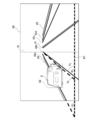
- the CPU 11 When the area corresponding to the lane marking is detected, the CPU 11 also obtains an angle including the horizon 61 in the image data 50 and the region corresponding to the lane marking for the lane markings 42a to 42d in FIG. 9A.
- the angle formed by the horizontal line 61 in the image data 50 is obtained for the lane markings 42a and 42b that define the lane in which the other vehicle 2 is traveling.
- the CPU 11 obtains the coordinates of two arbitrary points for the division lines 42a and 42b, respectively.
- the coordinates of the two points of the lane marking 42a are (x 11 , y 11 ) and (x 12 , y 12 ), and the coordinates of the two points of the lane marking 42b are (x 21 , y 21 ) and (x 22 , y 22 ). do.
- the CPU 11 calculates the angles ⁇ 1 and ⁇ 2 of the line segments passing through the arbitrary two points of the lane markings 42a and 42b by the following formulas.
- ⁇ 1 arctan ⁇ (y 12- y 11 ) / (x 12- x 11 ) ⁇
- ⁇ 2 arctan ⁇ (y 22- y 21 ) / (x 22- x 21 ) ⁇
- the CPU 11 includes an angle ⁇ c between a line segment 53 connecting the lowest coordinates of the front wheels and rear wheels existing on one side of the vehicle body of another vehicle and a horizontal line 61, and a region corresponding to the horizontal line 61 and lane markings 42a and 42b.
- the relative relationship is estimated using the angles ⁇ 1 and ⁇ 2. In the example of FIG. 9B, the relationship of ⁇ 1 ⁇ c ⁇ ⁇ 2 is established.
- the CPU 11 can presume that the other vehicle 2 is traveling in the lane sandwiched between the lane markings 42a and the lane markings 42b.
- the lane marking 42b is the first lane marking on the left side with respect to the center line 51. Therefore, the CPU 11 can estimate that the other vehicle 2 is traveling in the left lane with reference to the lane in which the own vehicle is traveling.
- angle phi 2 consisting of angle phi 1
- partition lines 42b and the horizontal line 61. consisting division line 42a and the horizontal line 61.
- Figure 9B the disclosure of It is not something that is done.
- the CPU 11 calculates an angle consisting of the horizon 61 for all of the lane markings detected by the lane marking detection unit 142, and compares the angle with the angle ⁇ c to compare with the angle ⁇ c, so that the other vehicle is based on the lane in which the own vehicle is traveling. It goes without saying that the relative relationship with the lane in which the vehicle travels may be estimated.
- the CPU 11 calculates an angle consisting of the horizontal line 61 for all the lane markings detected by the lane marking detection unit 142, and determines the angle ⁇ c with the angle consisting of the lane marking and the horizontal line as a threshold value. Therefore, it goes without saying that the relative relationship with the lane in which the other vehicle travels may be estimated based on the lane in which the own vehicle travels. That is, when the angles formed by the lane markings 41, 42c, 42d and the horizontal line 61 are ⁇ 3 , ⁇ 4 , and ⁇ 5 , respectively, if the CPU 11 has ⁇ 1 ⁇ ⁇ c ⁇ ⁇ 2 , the other vehicle is larger than the own vehicle.
- the CPU 11 may presume that the other vehicle 2 is traveling in the same lane as the own vehicle 1. Further, even when the other vehicle 2 is detected near the center line 51 of the image 50, the CPU 11 may presume that the other vehicle 2 is traveling in the same lane as the own vehicle 1. Further, if ⁇ 3 ⁇ ⁇ c ⁇ ⁇ 4 , the CPU 11 can estimate that the other vehicle 2 is traveling in the lane to the right of the own vehicle 1.
- the other vehicle state estimation unit 140 has a function of detecting that the lane marking 41 is the center line on the roadway , if ⁇ 3 ⁇ ⁇ c , the CPU 11 and the other vehicle 2 own themselves. It may be estimated that the vehicle is traveling in the opposite direction to the vehicle 1.
- the CPU 11 estimates the traveling lane of the other vehicle 2 based on the horizontal angle of the line segment 53 and the lane marking, but the CPU 11 may estimate the traveling lane of the other vehicle 2 based on the inclination of the line segment 53 and the lane marking. good. That is, the slope of the line segment 53 (y c2- y c1 ) / (x c2- x c1 ) is the slope of the lane marking 42a (y 12- y 11 ) / (x 12- x 11 ) and the lane marking 42b. If it is between the inclination (y 22- y 21 ) / (x 22- x 21 ), the CPU 11 may presume that the other vehicle 2 exists between the lane markings 42a and 42b.
- FIG. 12 is a diagram showing an example of image data 50. From the image data 50, the CPU 11 is a line segment with respect to the distance between the coordinates (x 11 , y 11 ) and (x 23 , y 23 ) on the left and right lane markings of the lane in which the other vehicle 2 is traveling. Find the difference or ratio of the distance between the coordinates (x c3, y c3 ) on 53 and (x 23 , y 23). By obtaining the difference or ratio, the CPU 11 can estimate how much margin the other vehicle 2 is traveling from the lane marking. In the example shown in FIG. 12, the CPU 11 can estimate from the above difference or ratio that the other vehicle 2 is traveling closer to the sidewalk side.
- the CPU 11 may estimate the traveling direction in which the other vehicle is traveling as the state of the other vehicle. Specifically, the CPU 11 may estimate the traveling direction of the other vehicle by recognizing the front or the back of the other vehicle from the image data.
- the CPU 11 determines whether or not the other vehicle 2 and the other vehicle 3 include parts existing on the back surface of the vehicle such as a tail lamp, a brake lamp, or a reflector portion by using an object recognition algorithm such as YOLO.
- the CPU 11 estimates whether the other vehicles 2 and 3 are facing the front or the back depending on whether or not the parts existing on the back of the vehicle are included. Further, the CPU 11 can estimate the traveling directions of the other vehicles 2 and 3 by using the estimation result of the front or the back in addition to the calculated line segment.
- the CPU 11 may estimate the traveling speed difference between the other vehicle and the own vehicle as the state of the other vehicle from two or more image data. Specifically, the CPU 11 can estimate the difference in traveling speed from the other vehicle as the state of the other vehicle from the image data captured at a plurality of times.
- the CPU 11 from the image data 50a at time t-n, the bottom of the coordinates of the rear wheel of the other vehicle 2 (x c1, y c1) obtaining a t-n. Similarly, the CPU 11 obtains the coordinates (x c1 , y c1 ) t of the lowermost part of the rear wheel of the other vehicle 2 from the image data 50b at the time t. Then, the CPU 11 calculates the movement vector of the lowermost part of the rear wheel of the other vehicle 2 between the two image data. The CPU 11 further acquires the speed of the own vehicle 1 from OBD (On-board diagnostics) or the like.
- OBD On-board diagnostics
- the CPU 11 can calculate the difference in traveling speed of the other vehicle 2 from the own vehicle 1 from the speed of the own vehicle 1 and the movement vector of the lowermost portion of the rear wheels of the other vehicle 2. Further, when the traveling speed of the own vehicle is used as a parameter related to the own vehicle as in the third embodiment described later, the traveling speed of the other vehicle is estimated by taking the sum of the traveling speed difference and the traveling speed of the own vehicle. You can also do it.
- the own vehicle and others at the time when the image is captured such as GPS coordinates or the traveling speed of the own vehicle.
- the parameters related to the own vehicle are, for example, the traveling speed of the own vehicle or the position information.
- FIG. 1B is a diagram showing a schematic configuration of a vehicle state estimation system including the vehicle state estimation device according to the third embodiment of the present disclosure.
- the vehicle state estimation system according to the third embodiment of the present disclosure is first implemented in that the vehicle state estimation device 10, the camera 20, and the GPS sensor 30 are mounted on the own vehicle 1. It differs from the embodiment and the second embodiment.
- the vehicle state estimation device 10 is a device that estimates the state of another vehicle based on the image captured by the camera 20 and the information output from the GPS sensor 30. For example, the state of a vehicle (other vehicle) other than the own vehicle 1 is estimated.
- the other vehicle is an example of the subject imaged in the same manner as in the first embodiment and the second embodiment, and may be a structure such as a signboard, a road sign, or a feature adjacent to the road.
- the vehicle state estimation device 10 uses the image data obtained by imaging the range including the road area in the traveling direction in which the own vehicle 1 is traveling and the position where the image data obtained by the GPS sensor 30 is captured. As the state of the other vehicle, at least one of the lane in which the other vehicle is traveling, the direction in which the other vehicle is traveling, and the speed in which the other vehicle is traveling is estimated.
- the GPS sensor 30 calculates the latitude and longitude of the own vehicle 1 on which the GPS sensor 30 is mounted by receiving GPS signals transmitted by a plurality of GPS satellites and performing a ranging calculation.
- the GPS sensor 30 outputs the calculated latitude and longitude to the vehicle state estimation device 10 as position data of the own vehicle 1. If the same function as the GPS sensor 30 is exhibited instead of the GPS sensor 30, the present disclosure uses a ground (road) -based position identification system (Ground Based Positioning System: GBPS) or the like. You may.
- GBPS Ground Based Positioning System
- FIG. 3C is a block diagram showing an example of the functional configuration of the vehicle state estimation device 10 according to the third embodiment. The explanation will be given with reference to FIG. 3C, focusing on the differences from the first embodiment and the second embodiment.
- the vehicle state estimation device 10 according to the third embodiment is different from the first embodiment and the second embodiment in that the own vehicle traveling lane estimation unit 120 is added.
- the input / output I / F 110 receives the image captured by the camera 20 and the data output from the GPS sensor 30, and supplies the received data to the own vehicle traveling lane estimation unit 120 and the other vehicle state estimation unit 140. .. Further, the input / output I / F 110 may output data representing the estimation result of the state of the other vehicle output from the other vehicle state estimation unit 140 to an external device (not shown).
- the external device may be, for example, a display or a speaker mounted on the own vehicle 1. Further, the input / output I / F 110 may be transmitted to a server existing outside the own vehicle or a vehicle other than the own vehicle by using a communication unit (not shown).
- the own vehicle traveling lane estimation unit 120 estimates the lane in which the own vehicle 1 is traveling.
- the own vehicle traveling lane estimation unit 120 includes an own vehicle traveling lane estimation unit 121.
- the own vehicle traveling lane estimation unit 121 acquires the latitude and longitude information of the own vehicle 1 transmitted from the GPS sensor 30. Further, the own vehicle traveling lane estimation unit 121 acquires information representing the road configuration corresponding to the latitude and longitude from the road information storage unit 131. Then, the own vehicle traveling lane estimation unit 121 estimates the lane in which the own vehicle 1 travels by using the acquired latitude and longitude information and the information representing the configuration of the corresponding road.
- the own vehicle traveling lane estimation unit 121 may perform the latitude. And the longitude information may be corrected.
- the own vehicle traveling lane estimation unit 121 may correct the latitude and longitude information by, for example, map matching processing, the traveling locus of the own vehicle 1, analysis of image data acquired from the camera 20 and the like. Then, the own vehicle traveling lane estimation unit 121 may estimate the lane in which the own vehicle 1 travels after correcting the latitude and longitude information.
- Information on the lane in which the own vehicle is traveling may be acquired from the outside. The outside may be acquired from, for example, another vehicle other than the other vehicle imaged by the camera mounted on the own vehicle, a camera arranged on the roadside, or the like.
- the storage unit 130 is provided in, for example, the ROM 12 or the storage 14.
- the storage unit 130 includes a road information storage unit 131 and each vehicle state storage unit 132.
- information representing the configuration of the road corresponding to the position may be stored in advance in association with the position data represented by the latitude and longitude.
- the information representing the road composition for example, the number of lanes in each of the up and down directions, the number of lane markings and lane markings, the type, and the shape are expressed by latitude and longitude information or a latitude and longitude substitution system. Information may be included.
- the information representing the composition of the road includes information expressing the presence / absence of sidewalks, shoulders, sidewalks and medians strips, and their widths in latitude and longitude information or latitude and longitude substitution systems. May be good.
- each vehicle state storage unit 132 stores, for example, the relative relationship between the own vehicle and the other vehicle estimated by the first embodiment or the second embodiment together with the time when the state of the relationship is estimated. good.
- the other vehicle state estimation unit 144 uses the relative relationship between the own vehicle and the other vehicle obtained by the first embodiment or the second embodiment and the lane in which the own vehicle is traveling to allow the other vehicle to move. Estimate the lane in which you are driving. The case where the relative relationship between the own vehicle and the other vehicle is the lane in which the other vehicle is traveling based on the lane in which the own vehicle is traveling is described. It is estimated that another vehicle is in the lane to the left of the lane in which the own vehicle is driving, and it is estimated that the own vehicle is in the third lane (assuming that it is in the rightmost lane). If this is the case, the other vehicle state estimation unit 144 can estimate that the other vehicle is traveling in the lane to the left of the third lane, so that the other vehicle is traveling in the second lane. presume.
- the vehicle state estimation process is performed by the CPU 11 reading the vehicle state estimation program from the ROM 12 or the storage 14, expanding the program into the RAM 13 and executing the program.
- the CPU 11 acquires the GPS data acquired by the GPS sensor 30 and the image data captured by the camera 20 (step S301).
- step S301 the CPU 11 estimates the traveling lane of the own vehicle using the GPS data acquired from the GPS sensor 30 (step S302).
- the own vehicle traveling lane estimation process in step S302 will be described in detail later.
- step S302 the CPU 11 estimates the relative relationship between the own vehicle and the other vehicle and the state of the other vehicle using the image data acquired from the camera 20 (step S303). Since the process of S303 is the same as that of the first embodiment and the second embodiment, detailed description of the process is omitted.
- the CPU 11 may use the estimation result of the traveling lane of the own vehicle as necessary when estimating the state of another vehicle.
- the CPU 11 outputs the other vehicle state information, which is the information on the state of the other vehicle, obtained by estimating the relative relationship between the own vehicle and the other vehicle and the state of the other vehicle to the external device ( Step S304).
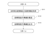
- the CPU 11 acquires the own vehicle position information representing the position information of the own vehicle 1 and the road information of the road on which the own vehicle 1 is traveling (step S111).
- the own vehicle position information is GPS data (N c , E c ).
- (N c , E c ) means that it is a set of latitude and longitude of the own vehicle 1.
- the CPU 11 acquires road information from the road information storage unit 131.
- step S111 the CPU 11 estimates the traveling lane of the own vehicle 1 based on the own vehicle position information and the road information (step S112).
- step S112 the CPU 11 outputs information on the traveling lane of the own vehicle 1 to each vehicle state storage unit 132 (step S113).
- FIG. 7 is a diagram for explaining the own vehicle traveling lane estimation process.
- the CPU 11 acquires information on the number of lanes related to the road on which the own vehicle 1 is traveling from the road information storage unit 131. Further, the CPU 11 acquires GPS data (N 01 , E 01 ) to (N 42 , E 42 ) of each section line constituting each lane. (N 01 , E 01 ) to (N 42 , E 42 ) mean that they are a set of latitude and longitude, respectively.
- the CPU 11 may correct the position information using the ground information. Further, the CPU 11 may correct the position information depending on how the surrounding buildings, road signs, traffic lights, roads in front, etc. are reflected in the camera 20.
- the median strip and the lane marking line are assumed to be solid lines, but the median strip or the lane marking line may be a broken line.
- the CPU 11 may additionally perform processing such as connecting the broken lines to each other and regarding the lane marking line as one solid line.
- the CPU 11 may use GPS data indicating the positions of those objects.
- the position information of virtual center lines at both left and right ends of the road may be used as temporary GPS data.
- the CPU 11 calculates the change in the distance between the own vehicle and the other vehicle as a relative relationship between the own vehicle and the other vehicle. Since the specific calculation method is described in the second embodiment, it will be omitted.
- the CPU 11 uses the difference in the time between the two images captured for calculating the change in the distance between the own vehicle and the other vehicle and the change in the distance to increase the speed between the own vehicle and the other vehicle. Calculate the difference. Then, the CPU 11 can estimate the speed at which the other vehicle is traveling by taking the sum of the speed of the own vehicle obtained as an external parameter and the calculated speed difference.
- the CPU 11 may calculate the distance from the lane marking of another vehicle after converting it into latitude and longitude information in real space instead of using the coordinates on the image data. Further, the CPU 11 may calculate the distance of another vehicle from the lane marking as a specific numerical value by using the width information between the lane markings acquired from the road network data, the dynamic map, or the like. Further, the CPU 11 may calculate the distance of another vehicle from the lane marking after converting the image so that the angle of each lane marking and the line segment from the horizontal becomes 90 degrees by affine transformation.
- FIG. 8B is a flowchart showing the details of the other vehicle state estimation process shown in step S303 of FIG. 4C.
- the CPU 11 acquires image data from the camera 20 (step S321). In parallel with the acquisition of the image data from the camera 20, the CPU 11 acquires the information on the traveling lane of the own vehicle 1 from each vehicle state storage unit 132 (step S322). In the present embodiment, the CPU 11 acquires the own vehicle traveling lane information that the own vehicle 1 is traveling in the second lane from the left from FIG. 7.
- the CPU 11 uses the image data acquired from the camera 20, the CPU 11 detects another vehicle existing in the image data (step S323) and also detects a lane marking existing in the image data (step S324).
- the CPU 11 reveals areas on the image data of other vehicles and lane markings existing in the image data.
- FIG. 9A is a diagram showing an example in which another vehicle and a lane marking are detected from a certain image data.
- the CPU 11 grasps the number of the median strip 41 and the division lines 42a to 42d in the image data 50 shown in FIG. 9 on the left or right side of the center line 51 of the image data 50.
- the lane marking 42b is the first presence on the left when viewed from the center line 51
- the lane marking 42a is the second presence on the left when viewed from the center line 51. Therefore, the own vehicle traveling lane is between the lane marking 42b and the median strip 41.
- the CPU 11 detects the other vehicle 2 and the circumscribing rectangle 52 relating to the shape of the other vehicle 2 from the image data 50 shown in FIG. 9A.
- the CPU 11 may detect it by using an object detection algorithm such as YOLO, for example.
- an object detection algorithm such as YOLO, for example.
- the CPU 11 detects the area in which the other vehicle 2 is imaged for each other vehicle 2.
- the CPU 11 uses, for example, a white line recognition system (see IPSJ 69th National Convention, "Development of a white line recognition system for moving images of automobile cameras", etc.) when detecting a lane marking in image data.
- a white line recognition system see IPSJ 69th National Convention, "Development of a white line recognition system for moving images of automobile cameras", etc.
- the above-mentioned YOLO, machine learning, or the like may be used.
- the CPU 11 acquires information on the traveling lane of the own vehicle, detects another vehicle and a lane marking, and then estimates the state of the detected other vehicle (step S325).
- the CPU 11 estimates, for example, the traveling direction, the traveling lane, or the speed of the other vehicle as the state of the other vehicle.
- the method of estimating the state of the other vehicle is the same as that of the first embodiment or the second embodiment.
- the CPU 11 obtains an angle from the horizontal in the image data 50 with respect to the median strip 41 and the division lines 42a to 42d.
- the method of obtaining the angle from the horizontal in the image data 50 is the same as that in the second embodiment.
- step S325 the CPU 11 inputs the detected other vehicle state information, which is the detected other vehicle state information, into each vehicle state storage unit 132 (step S326).
- step S326 the CPU 11 outputs other vehicle status information to the external device (step S327).
- the CPU 11 can estimate the state of the other vehicle existing around the own vehicle based on the image data and the GPS data without communicating with the other vehicle. ..
- the CPU 11 may estimate the distance from the lane marking in the lane in which the other vehicle is traveling as the state of the other vehicle from the image data. By estimating the distance of the other vehicle from the lane marking, the CPU 11 can estimate how much margin the other vehicle 2 is traveling from the lane marking.
- the CPU 11 determines whether the other vehicle is parked or stopped based on, for example, the distance between the other vehicle and each lane marking and the speed of the other vehicle. You can also estimate whether or not.
- the CPU 11 acquires information such as the traveling direction of the own vehicle and the number of lanes in the opposite direction from the road network in addition to the lane in which the other vehicle is moving and the traveling direction of the other vehicle, so that the other vehicle travels in the reverse direction. It is also possible to estimate whether or not the vehicle is running.
- FIG. 13 is a diagram showing how the vehicle state estimation device 10 having a camera at the position of the sidewalk captures an image of a range including a road area. As shown in FIG. 13, even if the camera is on the sidewalk, the vehicle state estimation device 10 does not necessarily have to be mounted inside the vehicle as long as it can image a range including the road area.
- the vehicle The state estimation device 10 can apply the process according to the present embodiment. Further, the vehicle state estimation device 10 recognizes the "road area" in the image data by using, for example, a semantic segmentation technique (eg, http: // mi.eng.cam.ac.uk/projects/segment/). If the vehicle exists outside the range of the "road area", it may be presumed that the vehicle is parked or stopped in a parking lot or the like regardless of the orientation of other vehicles.
- a semantic segmentation technique eg, http: // mi.eng.cam.ac.uk/projects/segment/
- FIG. 14 is a diagram showing an example of image data.
- image data 50 shown in FIG. 14 other vehicles 2 and 4 facing in the lateral direction are shown. It is assumed that the other vehicle 2 is traveling on the road, but the other vehicle 4 is parked or stopped in a parking lot beside the road, not on the road.
- the CPU 11 determines the state of the vehicle by calculating the coordinates of the lowermost portions of the front wheels and the rear wheels of the vehicle and the line segments connecting the coordinates. Can be estimated. In the example of the image of FIG. 14, the CPU 11 can estimate that the other vehicle 2 is traveling in a direction orthogonal to the traveling direction of the own vehicle 1. Further, in the example of the image of FIG. 14, the CPU 11 can presume that the other vehicle 4 is parked or stopped because the other vehicle 4 is not on the road.
- the vehicle state estimation device 10 uses the two coordinates of the front wheels and the rear wheels of the other vehicle, but the present disclosure is not limited to this.
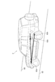
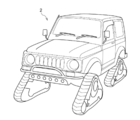
- 15 to 18 are views showing a special vehicle. Even when a special vehicle as shown in FIGS. 15 to 18 is shown in the image data, the vehicle state estimation device 10 can estimate the state of the vehicle by obtaining the coordinates of the vehicle.
- the vehicle state estimation device 10 may use the coordinates of all or part of the three or more wheels. Further, the vehicle state estimation device 10 may use the coordinates of the two wheels if the vehicle travels on only two wheels, such as a motorcycle. Further, for example, in the case of the vehicle shown in FIG. 16 in which a spare tire is mounted on the back surface of the vehicle, the vehicle state estimation device 10 may recognize the back surface and ignore the spare tire on the back surface. good.
- the vehicle state estimation device 10 defines that the shape of the wheel is not only a circle but also a substantially triangular one having an arc-shaped apex, and then the front wheel. And the rear wheels may be recognized from the image data.
- the vehicle state estimation device 10 is a "tricycle" so as to label the vehicle or motorcycle when the vehicle is detected by YOLO or the like. The process may be different from that for two-wheeled vehicles and four-wheeled vehicles. Then, when the vehicle state estimation device 10 detects that the vehicle is a tricycle, it may acquire a plurality of feature points of the rear wheels, calculate the inclination between the feature points, and use the calculated inclination for estimating the state. Further, in the case of a three-wheeled vehicle, the vehicle state estimation device 10 may further detect a side step of the vehicle or a shadow cast by the vehicle on the ground surface instead of the wheels, and use the detected coordinates.
- various processors other than the CPU may execute the vehicle state estimation process executed by the CPU reading the software (program) in each of the above embodiments.
- the processors include PLD (Programmable Logic Device) whose circuit configuration can be changed after manufacturing FPGA (Field-Programmable Gate Array), and ASIC (Application Specific Integrated Circuit) for executing ASIC (Application Special Integrated Circuit).
- An example is a dedicated electric circuit or the like, which is a processor having a circuit configuration designed exclusively for the purpose.
- the vehicle state estimation process may be executed by one of these various processors, or a combination of two or more processors of the same type or different types (for example, a plurality of FPGAs, and a CPU and an FPGA). It may be executed by combination etc.).
- the hardware structure of these various processors is, more specifically, an electric circuit in which circuit elements such as semiconductor elements are combined.
- the program is a non-temporary storage medium such as a CD-ROM (Compact Disk Read Only Memory), a DVD-ROM (Digital entirely Disk Online Memory), and a USB (Universal Serial Bus) memory. It may be provided in the form. Further, the program may be downloaded from an external device via a network.
- a vehicle state estimation device that estimates the position or state of a vehicle. Memory and With at least one processor connected to the memory Including The processor Get an image that includes the vehicle you want to estimate The position of the target vehicle to be estimated based on the image pickup device that captured the image using a line segment connecting at least two points selected from the region where the vehicle to be estimated is imaged in the image. Or a vehicle condition estimator configured to estimate the condition.
- a non-temporary storage medium that stores a program that can be executed by a computer to execute a vehicle state estimation process that estimates the position or state of a vehicle.
- the vehicle state estimation process is Get an image that includes the vehicle you want to estimate The position of the target vehicle to be estimated based on the image pickup device that captured the image using a line segment connecting at least two points selected from the region where the vehicle to be estimated is imaged in the image. Or estimate the state, Non-temporary storage medium.
Landscapes
- Engineering & Computer Science (AREA)
- Physics & Mathematics (AREA)
- Automation & Control Theory (AREA)
- Mathematical Physics (AREA)
- Transportation (AREA)
- Mechanical Engineering (AREA)
- General Physics & Mathematics (AREA)
- Multimedia (AREA)
- Theoretical Computer Science (AREA)
- Traffic Control Systems (AREA)
- Control Of Driving Devices And Active Controlling Of Vehicle (AREA)
- Image Analysis (AREA)
Priority Applications (3)
| Application Number | Priority Date | Filing Date | Title |
|---|---|---|---|
| US17/799,636 US20230085455A1 (en) | 2020-02-20 | 2020-02-20 | Vehicle condition estimation method, vehicle condition estimation device, and vehicle condition estimation program |
| JP2022501515A JP7380824B2 (ja) | 2020-02-20 | 2020-02-20 | 車両状態推定方法、車両状態推定装置、及び車両状態推定プログラム |
| PCT/JP2020/006829 WO2021166169A1 (ja) | 2020-02-20 | 2020-02-20 | 車両状態推定方法、車両状態推定装置、及び車両状態推定プログラム |
Applications Claiming Priority (1)
| Application Number | Priority Date | Filing Date | Title |
|---|---|---|---|
| PCT/JP2020/006829 WO2021166169A1 (ja) | 2020-02-20 | 2020-02-20 | 車両状態推定方法、車両状態推定装置、及び車両状態推定プログラム |
Publications (1)
| Publication Number | Publication Date |
|---|---|
| WO2021166169A1 true WO2021166169A1 (ja) | 2021-08-26 |
Family
ID=77390797
Family Applications (1)
| Application Number | Title | Priority Date | Filing Date |
|---|---|---|---|
| PCT/JP2020/006829 Ceased WO2021166169A1 (ja) | 2020-02-20 | 2020-02-20 | 車両状態推定方法、車両状態推定装置、及び車両状態推定プログラム |
Country Status (3)
| Country | Link |
|---|---|
| US (1) | US20230085455A1 (https=) |
| JP (1) | JP7380824B2 (https=) |
| WO (1) | WO2021166169A1 (https=) |
Families Citing this family (5)
| Publication number | Priority date | Publication date | Assignee | Title |
|---|---|---|---|---|
| JP7355216B2 (ja) * | 2020-03-05 | 2023-10-03 | 日本電信電話株式会社 | 管理装置、管理方法及び管理プログラム |
| KR20220031224A (ko) * | 2020-09-04 | 2022-03-11 | 현대자동차주식회사 | 차량 및 그 제어방법 |
| US20230043040A1 (en) * | 2021-08-06 | 2023-02-09 | Peter Cooper | System for controlling classes of an e-bike |
| US11845439B2 (en) * | 2021-09-29 | 2023-12-19 | Canoo Technologies Inc. | Prediction of target object's behavior based on world and image frames |
| CN115984806B (zh) * | 2023-03-20 | 2023-06-13 | 四川京炜数字科技有限公司 | 道路标线破损动态检测系统 |
Citations (5)
| Publication number | Priority date | Publication date | Assignee | Title |
|---|---|---|---|---|
| JP2011113330A (ja) * | 2009-11-27 | 2011-06-09 | Fuji Heavy Ind Ltd | 物体検出装置および運転支援システム |
| JP2015225546A (ja) * | 2014-05-28 | 2015-12-14 | 本田技研工業株式会社 | 物体検出装置、運転支援装置、物体検出方法、および物体検出プログラム |
| JP2016192177A (ja) * | 2015-03-31 | 2016-11-10 | 株式会社デンソーアイティーラボラトリ | 車両検出システム、車両検出装置、車両検出方法、及び車両検出プログラム |
| CN110246183A (zh) * | 2019-06-24 | 2019-09-17 | 百度在线网络技术(北京)有限公司 | 车轮接地点检测方法、装置及存储介质 |
| JP2019196164A (ja) * | 2018-05-09 | 2019-11-14 | 東軟集団股▲分▼有限公司 | 車両位置検出方法及び装置 |
Family Cites Families (8)
| Publication number | Priority date | Publication date | Assignee | Title |
|---|---|---|---|---|
| JP2004227293A (ja) | 2003-01-23 | 2004-08-12 | Nissan Motor Co Ltd | 側方車両検出装置 |
| JP2008046761A (ja) | 2006-08-11 | 2008-02-28 | Sumitomo Electric Ind Ltd | 移動体画像処理システム、装置及び方法 |
| DE112012006147B8 (de) | 2012-03-29 | 2018-09-06 | Toyota Jidosha Kabushiki Kaisha | Straßenoberflächen-Zustands-Bestimmungsvorrichtung |
| KR102374921B1 (ko) * | 2015-10-30 | 2022-03-16 | 주식회사 만도모빌리티솔루션즈 | 차량 제어 시스템 및 방법 |
| WO2017158983A1 (ja) | 2016-03-18 | 2017-09-21 | 株式会社Jvcケンウッド | 物体認識装置、物体認識方法及び物体認識プログラム |
| KR102215325B1 (ko) * | 2017-02-28 | 2021-02-15 | 현대자동차주식회사 | 차량의 위치 추정 장치 및 방법과 이를 이용한 차량 |
| CN107577988B (zh) * | 2017-08-03 | 2020-05-26 | 东软集团股份有限公司 | 实现侧方车辆定位的方法、装置及存储介质、程序产品 |
| US10586456B2 (en) * | 2018-04-27 | 2020-03-10 | TuSimple | System and method for determining car to lane distance |
-
2020
- 2020-02-20 JP JP2022501515A patent/JP7380824B2/ja active Active
- 2020-02-20 US US17/799,636 patent/US20230085455A1/en not_active Abandoned
- 2020-02-20 WO PCT/JP2020/006829 patent/WO2021166169A1/ja not_active Ceased
Patent Citations (5)
| Publication number | Priority date | Publication date | Assignee | Title |
|---|---|---|---|---|
| JP2011113330A (ja) * | 2009-11-27 | 2011-06-09 | Fuji Heavy Ind Ltd | 物体検出装置および運転支援システム |
| JP2015225546A (ja) * | 2014-05-28 | 2015-12-14 | 本田技研工業株式会社 | 物体検出装置、運転支援装置、物体検出方法、および物体検出プログラム |
| JP2016192177A (ja) * | 2015-03-31 | 2016-11-10 | 株式会社デンソーアイティーラボラトリ | 車両検出システム、車両検出装置、車両検出方法、及び車両検出プログラム |
| JP2019196164A (ja) * | 2018-05-09 | 2019-11-14 | 東軟集団股▲分▼有限公司 | 車両位置検出方法及び装置 |
| CN110246183A (zh) * | 2019-06-24 | 2019-09-17 | 百度在线网络技术(北京)有限公司 | 车轮接地点检测方法、装置及存储介质 |
Also Published As
| Publication number | Publication date |
|---|---|
| JPWO2021166169A1 (https=) | 2021-08-26 |
| US20230085455A1 (en) | 2023-03-16 |
| JP7380824B2 (ja) | 2023-11-15 |
Similar Documents
| Publication | Publication Date | Title |
|---|---|---|
| US12106574B2 (en) | Image segmentation | |
| US12140442B2 (en) | Clustering event information for vehicle navigation | |
| JP7380824B2 (ja) | 車両状態推定方法、車両状態推定装置、及び車両状態推定プログラム | |
| US20220397402A1 (en) | Systems and methods for determining road safety | |
| US11814079B2 (en) | Systems and methods for identifying potential communication impediments | |
| CN112740225B (zh) | 一种路面要素确定方法及装置 | |
| US12208791B2 (en) | Systems and methods for selectively decelerating a vehicle | |
| CN112106065B (zh) | 使用车轮旋转的光学跟踪预测被观察车辆的状态和位置 | |
| US11254329B2 (en) | Systems and methods for compression of lane data | |
| US11200433B2 (en) | Detection and classification systems and methods for autonomous vehicle navigation | |
| WO2021053393A1 (en) | Systems and methods for monitoring traffic lane congestion | |
| EP3818339A1 (en) | Systems and methods for vehicle navigation | |
| WO2019007263A1 (zh) | 车载传感器的外部参数标定的方法和设备 | |
| US20240391494A1 (en) | Radar-camera fusion for vehicle navigation | |
| US12400114B2 (en) | Reducing stored parameters for a navigation system | |
| WO2020004231A1 (ja) | レーン推定装置、方法およびプログラム | |
| CN117470258A (zh) | 一种地图构建方法、装置、设备及介质 | |
| US11967159B2 (en) | Semantic annotation of sensor data with overlapping physical features | |
| US20260024324A1 (en) | High Definition Map Fusion for 3D Object Detection | |
| Alrousan et al. | Multi-sensor fusion in slow lanes for lane keep assist system | |
| CN115985109B (zh) | 一种无人驾驶矿车环境感知方法和系统 | |
| US20260038255A1 (en) | Fusion graph neural network | |
| CN119027476A (zh) | 用于确定自由空间的方法和装置 | |
| WO2023146788A1 (en) | Semantic annotation of sensor data with overlapping physical features | |
| CN121191312A (zh) | 一种数据处理方法、系统及介质 |
Legal Events
| Date | Code | Title | Description |
|---|---|---|---|
| 121 | Ep: the epo has been informed by wipo that ep was designated in this application |
Ref document number: 20919969 Country of ref document: EP Kind code of ref document: A1 |
|
| ENP | Entry into the national phase |
Ref document number: 2022501515 Country of ref document: JP Kind code of ref document: A |
|
| NENP | Non-entry into the national phase |
Ref country code: DE |
|
| 122 | Ep: pct application non-entry in european phase |
Ref document number: 20919969 Country of ref document: EP Kind code of ref document: A1 |