WO2021166169A1 - Vehicle condition estimation method, vehicle condition estimation device and vehicle condition estimation program - Google Patents
Vehicle condition estimation method, vehicle condition estimation device and vehicle condition estimation program Download PDFInfo
- Publication number
- WO2021166169A1 WO2021166169A1 PCT/JP2020/006829 JP2020006829W WO2021166169A1 WO 2021166169 A1 WO2021166169 A1 WO 2021166169A1 JP 2020006829 W JP2020006829 W JP 2020006829W WO 2021166169 A1 WO2021166169 A1 WO 2021166169A1
- Authority
- WO
- WIPO (PCT)
- Prior art keywords
- vehicle
- estimated
- lane
- image
- state estimation
- Prior art date
Links
- 238000000034 method Methods 0.000 title claims abstract description 63
- 230000010365 information processing Effects 0.000 claims abstract description 3
- 238000003384 imaging method Methods 0.000 abstract description 6
- 238000001514 detection method Methods 0.000 description 27
- 238000010586 diagram Methods 0.000 description 20
- 238000005516 engineering process Methods 0.000 description 11
- 238000012545 processing Methods 0.000 description 9
- 238000004891 communication Methods 0.000 description 8
- 238000004364 calculation method Methods 0.000 description 3
- 238000013527 convolutional neural network Methods 0.000 description 3
- 238000011161 development Methods 0.000 description 3
- 230000018109 developmental process Effects 0.000 description 3
- 238000000605 extraction Methods 0.000 description 3
- 230000006870 function Effects 0.000 description 3
- 238000010801 machine learning Methods 0.000 description 3
- 239000000203 mixture Substances 0.000 description 3
- 238000009434 installation Methods 0.000 description 2
- 230000011218 segmentation Effects 0.000 description 2
- 238000006467 substitution reaction Methods 0.000 description 2
- PXFBZOLANLWPMH-UHFFFAOYSA-N 16-Epiaffinine Natural products C1C(C2=CC=CC=C2N2)=C2C(=O)CC2C(=CC)CN(C)C1C2CO PXFBZOLANLWPMH-UHFFFAOYSA-N 0.000 description 1
- 230000004931 aggregating effect Effects 0.000 description 1
- 238000004458 analytical method Methods 0.000 description 1
- 238000013459 approach Methods 0.000 description 1
- 238000013528 artificial neural network Methods 0.000 description 1
- 210000000746 body region Anatomy 0.000 description 1
- 238000006243 chemical reaction Methods 0.000 description 1
- 230000000295 complement effect Effects 0.000 description 1
- 238000009792 diffusion process Methods 0.000 description 1
- 239000012530 fluid Substances 0.000 description 1
- 239000004973 liquid crystal related substance Substances 0.000 description 1
- 238000004519 manufacturing process Methods 0.000 description 1
- 229910044991 metal oxide Inorganic materials 0.000 description 1
- 150000004706 metal oxides Chemical class 0.000 description 1
- 238000005192 partition Methods 0.000 description 1
- 239000004065 semiconductor Substances 0.000 description 1
- 239000007787 solid Substances 0.000 description 1
- 230000009466 transformation Effects 0.000 description 1
Images


Classifications
-
- G—PHYSICS
- G06—COMPUTING; CALCULATING OR COUNTING
- G06V—IMAGE OR VIDEO RECOGNITION OR UNDERSTANDING
- G06V20/00—Scenes; Scene-specific elements
- G06V20/50—Context or environment of the image
- G06V20/56—Context or environment of the image exterior to a vehicle by using sensors mounted on the vehicle
- G06V20/588—Recognition of the road, e.g. of lane markings; Recognition of the vehicle driving pattern in relation to the road
-
- B—PERFORMING OPERATIONS; TRANSPORTING
- B60—VEHICLES IN GENERAL
- B60W—CONJOINT CONTROL OF VEHICLE SUB-UNITS OF DIFFERENT TYPE OR DIFFERENT FUNCTION; CONTROL SYSTEMS SPECIALLY ADAPTED FOR HYBRID VEHICLES; ROAD VEHICLE DRIVE CONTROL SYSTEMS FOR PURPOSES NOT RELATED TO THE CONTROL OF A PARTICULAR SUB-UNIT
- B60W40/00—Estimation or calculation of non-directly measurable driving parameters for road vehicle drive control systems not related to the control of a particular sub unit, e.g. by using mathematical models
- B60W40/02—Estimation or calculation of non-directly measurable driving parameters for road vehicle drive control systems not related to the control of a particular sub unit, e.g. by using mathematical models related to ambient conditions
- B60W40/04—Traffic conditions
-
- B—PERFORMING OPERATIONS; TRANSPORTING
- B60—VEHICLES IN GENERAL
- B60W—CONJOINT CONTROL OF VEHICLE SUB-UNITS OF DIFFERENT TYPE OR DIFFERENT FUNCTION; CONTROL SYSTEMS SPECIALLY ADAPTED FOR HYBRID VEHICLES; ROAD VEHICLE DRIVE CONTROL SYSTEMS FOR PURPOSES NOT RELATED TO THE CONTROL OF A PARTICULAR SUB-UNIT
- B60W40/00—Estimation or calculation of non-directly measurable driving parameters for road vehicle drive control systems not related to the control of a particular sub unit, e.g. by using mathematical models
- B60W40/10—Estimation or calculation of non-directly measurable driving parameters for road vehicle drive control systems not related to the control of a particular sub unit, e.g. by using mathematical models related to vehicle motion
- B60W40/105—Speed
-
- G—PHYSICS
- G06—COMPUTING; CALCULATING OR COUNTING
- G06V—IMAGE OR VIDEO RECOGNITION OR UNDERSTANDING
- G06V20/00—Scenes; Scene-specific elements
- G06V20/50—Context or environment of the image
- G06V20/56—Context or environment of the image exterior to a vehicle by using sensors mounted on the vehicle
- G06V20/58—Recognition of moving objects or obstacles, e.g. vehicles or pedestrians; Recognition of traffic objects, e.g. traffic signs, traffic lights or roads
-
- B—PERFORMING OPERATIONS; TRANSPORTING
- B60—VEHICLES IN GENERAL
- B60W—CONJOINT CONTROL OF VEHICLE SUB-UNITS OF DIFFERENT TYPE OR DIFFERENT FUNCTION; CONTROL SYSTEMS SPECIALLY ADAPTED FOR HYBRID VEHICLES; ROAD VEHICLE DRIVE CONTROL SYSTEMS FOR PURPOSES NOT RELATED TO THE CONTROL OF A PARTICULAR SUB-UNIT
- B60W2420/00—Indexing codes relating to the type of sensors based on the principle of their operation
- B60W2420/40—Photo or light sensitive means, e.g. infrared sensors
- B60W2420/403—Image sensing, e.g. optical camera
-
- B—PERFORMING OPERATIONS; TRANSPORTING
- B60—VEHICLES IN GENERAL
- B60W—CONJOINT CONTROL OF VEHICLE SUB-UNITS OF DIFFERENT TYPE OR DIFFERENT FUNCTION; CONTROL SYSTEMS SPECIALLY ADAPTED FOR HYBRID VEHICLES; ROAD VEHICLE DRIVE CONTROL SYSTEMS FOR PURPOSES NOT RELATED TO THE CONTROL OF A PARTICULAR SUB-UNIT
- B60W2552/00—Input parameters relating to infrastructure
- B60W2552/53—Road markings, e.g. lane marker or crosswalk
-
- B—PERFORMING OPERATIONS; TRANSPORTING
- B60—VEHICLES IN GENERAL
- B60W—CONJOINT CONTROL OF VEHICLE SUB-UNITS OF DIFFERENT TYPE OR DIFFERENT FUNCTION; CONTROL SYSTEMS SPECIALLY ADAPTED FOR HYBRID VEHICLES; ROAD VEHICLE DRIVE CONTROL SYSTEMS FOR PURPOSES NOT RELATED TO THE CONTROL OF A PARTICULAR SUB-UNIT
- B60W2554/00—Input parameters relating to objects
- B60W2554/80—Spatial relation or speed relative to objects
Definitions
- the disclosed technology relates to a vehicle state estimation method, a vehicle state estimation device, and a vehicle state estimation program.
- Non-Patent Document 1 reports on a technique relating to driving control or driving support of an automobile.
- the state of the other vehicle such as which lane the vehicle other than the own vehicle (hereinafter referred to as the other vehicle) is traveling at what speed and in which direction, and the information of the other vehicle are integrated into the lane.
- Accurately recognizing each traffic flow is extremely important for safely controlling the running of the own vehicle.
- the disclosed technology was made in view of the above points, and is a vehicle state estimation method and a vehicle that enable the relationship between the own vehicle and another vehicle and the state of the other vehicle to be estimated without using special equipment. It is an object of the present invention to provide a state estimation device and a vehicle state estimation program.
- the first aspect of the present disclosure is a vehicle state estimation method in which an information processing device including a processor and a memory connected to the processor estimates the position or state of a vehicle, and an image including an image to be estimated is displayed. Using a line segment connecting at least two points selected from the region in which the vehicle to be estimated is captured in the image, the estimation target is based on the image pickup device that captured the image. Estimate the position or condition of the vehicle.
- a second aspect of the present disclosure is a vehicle state estimation device that estimates the position or state of a vehicle, wherein an image acquisition unit that acquires an image including the vehicle to be estimated and the vehicle to be estimated in the image are Another vehicle state estimation unit that estimates the position or state of the target vehicle to be estimated based on the image pickup device that captured the image using a line segment connecting at least two points selected from the imaged region. And.
- a third aspect of the present disclosure is a vehicle state estimation program that causes a computer to estimate the position or state of a vehicle, and obtains an image including the vehicle to be estimated by the computer, and the vehicle to be estimated in the image. Using a line segment connecting at least two points selected from the region in which the image is imaged, a process of estimating the position or state of the vehicle to be estimated is executed based on the image pickup device that captured the image. ..
- a vehicle state estimation device by analyzing an image including the vehicle to be estimated taken from a known position, the state of the other vehicle without obtaining information from the other vehicle and without using special equipment.
- a vehicle state estimation device by analyzing an image including the vehicle to be estimated taken from a known position, the state of the other vehicle without obtaining information from the other vehicle and without using special equipment.
- a vehicle state estimation device by analyzing an image including the vehicle to be estimated taken from a known position, the state of the other vehicle without obtaining information from the other vehicle and without using special equipment.
- the former relationship includes the position of the second vehicle with respect to the first vehicle, the traveling direction of the second vehicle with respect to the traveling direction of the first vehicle, and the like.
- the latter relationship includes the speed of the second vehicle, the lane in which it is traveling, or the direction in which it is traveling.
- the first vehicle is assumed to be the own vehicle and the second vehicle is assumed to be another vehicle, but the disclosed technology is that both the first vehicle and the second vehicle are other vehicles. good.
- the traffic flow on the road may be estimated based on the above relationship.
- the second vehicle shown in the image taken from the first vehicle (hereinafter referred to as own vehicle) and the own vehicle are relative to each other.
- the relationship is estimated from the above image. More specifically, the relative relationship is estimated using a line segment connecting at least two arbitrary points in the region where the other vehicle is imaged in the image.
- the relative relationship obtained here may be used, for example, for controlling a vehicle in automatic driving.
- information that can be acquired by a sensor mounted on the own vehicle and information necessary for estimation from another subject captured in the above image are obtained, and the obtained information is used.
- the information that can be acquired by the sensor mounted on the own vehicle includes, for example, the position of the own vehicle obtained by GPS (Global Positioning System) or the speed obtained from the speed sensor.
- Information required for estimation obtained from other subjects captured in the above image includes, for example, a line that divides a road lane. As a more specific example, the lane in which another vehicle is traveling can be estimated by using the relative relationship with the position of the own vehicle.
- the absolute relationship thus obtained can be used for lane pricing or traffic flow estimation.
- FIG. 1A is a diagram showing a schematic configuration of a vehicle state estimation system including a vehicle state estimation device according to the present embodiment.
- the vehicle state estimation device 10 and the camera 20 are mounted on the own vehicle 1.
- the vehicle state estimation device 10 estimates the relative relationship between the own vehicle 1 and the other vehicle shown in the image captured from any position of the own vehicle 1.
- the relative relationship referred to here is the position or traveling direction of another vehicle with respect to the own vehicle 1.
- the vehicle state estimation device 10 is a device that estimates the state of the object to be estimated based on the image captured by the camera 20.
- the state in the first embodiment is the relative relationship between the other vehicle and the own vehicle 1 as described above.
- the other vehicle is an example of the subject being imaged, and the subject being imaged may be a subject existing on the road such as a manhole or a road marking.
- the relative relationship is the position or direction of travel of another vehicle with respect to the own vehicle.
- the vehicle state estimation device 10 uses image data obtained by imaging a range including a road area in the traveling direction in which the own vehicle 1 is traveling, and uses the position of the own vehicle 1 at the time when another vehicle is imaged as a reference. Estimate the condition of other vehicles. An example of the functional configuration of the vehicle state estimation device 10 will be described in detail later.
- the camera 20 is an image pickup device using a solid-state image pickup device such as a CMOS (Complementary Metal Oxide Sensor) sensor, for example.
- CMOS Complementary Metal Oxide Sensor
- the installation location, elevation angle, and azimuth angle of the camera 20 are set so that at least the road region in the traveling direction in which the own vehicle 1 is traveling is included in the imaging range. Then, the camera 20 outputs the image data obtained by imaging the range including the road region in the traveling direction of the own vehicle 1 to the vehicle state estimation device 10.
- the camera 20 may be provided exclusively for estimating the state of another vehicle by the vehicle state estimation device 10, or may use a camera mounted on the own vehicle 1 for a purpose other than estimating the state of the other vehicle. May be good.
- a camera mounted on the own vehicle 1 may be used for a purpose other than estimating the state of another vehicle, such as a drive recorder or a stereo camera for measuring the distance between vehicles.
- a camera provided on the driver's helmet or steering wheel may be used as the camera 20.
- a camera provided in a mobile terminal such as a smartphone owned by a passenger of the own vehicle 1 may be used as the camera 20.
- any installed camera may be used as the camera 20 as long as the surrounding environment of the own vehicle 1 can be imaged.
- the camera arranged in the own vehicle 1 may also capture images in any of the front, rear, and side directions.
- the camera 20 may be an infrared camera that detects infrared rays.
- the image data output by the camera 20 may be moving image data, or may be still image data captured at regular time intervals.
- an image captured by a camera installed on the roadside may be used instead of the camera 20 mounted on the own vehicle 1, an image captured by a camera installed on the roadside may be used. In this case, the vehicle state estimation device 10 estimates the relative positional relationship between the position of the camera installed on the roadside and another vehicle.
- FIG. 2 is a block diagram showing the hardware configuration of the vehicle state estimation device 10.
- the vehicle state estimation device 10 includes a CPU (Central Processing Unit) 11, a ROM (Read Only Memory) 12, a RAM (Random Access Memory) 13, a storage 14, an input unit 15, a display unit 16, and communication. It has an interface (I / F) 17.
- the configurations are connected to each other via a bus 19 so as to be communicable with each other.
- the CPU 11 is a central arithmetic processing unit that executes various programs and controls each part. That is, the CPU 11 reads the program from the ROM 12 or the storage 14, and executes the program using the RAM 13 as a work area. The CPU 11 controls each of the above configurations and performs various arithmetic processes according to the program stored in the ROM 12 or the storage 14. In the present embodiment, the ROM 12 or the storage 14 stores a vehicle state estimation program for estimating the state of another vehicle.
- the ROM 12 stores various programs and various data.
- the RAM 13 temporarily stores a program or data as a work area.
- the storage 14 is composed of a storage device such as an HDD (Hard Disk Drive) or an SSD (Solid State Drive), and stores various programs including an operating system and various data.
- the input unit 15 includes a pointing device such as a mouse and a keyboard, and is used for performing various inputs.
- the display unit 16 is, for example, a liquid crystal display and displays various types of information.
- the display unit 16 may adopt a touch panel method and function as an input unit 15.
- the communication interface 17 is an interface for communicating with other devices such as an external device, and a wireless communication standard represented by, for example, 4G, 5G, Wi-Fi (registered trademark), etc. is used.
- FIG. 3A is a block diagram showing an example of the functional configuration of the vehicle state estimation device 10.
- the vehicle state estimation device 10 has an input / output interface (I / F) 110, a storage unit 130, and another vehicle state estimation unit 140 as functional configurations.
- Each functional configuration is realized by the CPU 11 reading the vehicle state estimation program stored in the ROM 12 or the storage 14, deploying the program in the RAM 13, and executing the program.
- the input / output I / F 110 receives the image captured by the camera 20 and supplies the received data to the other vehicle state estimation unit 140. Further, the input / output I / F 110 may output data representing the estimation result of the state of the other vehicle output from the other vehicle state estimation unit 140 to an external device (not shown).
- the external device may be, for example, a display or a speaker mounted on the own vehicle 1.
- the storage unit 130 is provided in, for example, the ROM 12 or the storage 14.
- the storage unit 130 includes each vehicle state storage unit 132.
- each vehicle state storage unit 132 the relative relationship with the other vehicle based on the own vehicle 1 estimated by the other vehicle state estimation unit 144 is stored together with the time when the relationship is estimated.
- the other vehicle state estimation unit 140 estimates the relative relationship between the own vehicle 1 and the other vehicle.
- the other vehicle state estimation unit 140 includes an image acquisition unit 141, another vehicle detection unit 143, and another vehicle state estimation unit 144.
- the image acquisition unit 141 sequentially captures the image data output from the camera 20 via the input / output I / F 110.
- the image acquisition unit 141 associates the captured image data with information indicating the imaging timing or reception timing of the image data, and outputs the captured image data to the other vehicle detection unit 143.
- the image acquisition unit 141 cuts out the still image data at a predetermined frame cycle and outputs it to the lane marking detection unit 142 and the other vehicle detection unit 143. You may.
- the image acquisition unit 141 may perform a calibration process for removing noise and correcting individual differences in the performance of the camera 20 or inclination at the time of installation of the still image data.
- an image acquisition unit (not shown) is prepared outside the other vehicle state estimation unit 140, and image data is output to the other vehicle detection unit 143 from the image acquisition unit prepared externally. May be good.
- the other vehicle detection unit 143 detects an area on the image data in which the other vehicle is imaged from the image data received from the image acquisition unit 141. This area may be rectangular. When the area is a rectangle, the coordinates of the rectangle on the image data are calculated. The other vehicle detection unit 143 sends information on the coordinates of the circumscribed rectangle circumscribing the detected area on the image data of the other vehicle to the other vehicle state estimation unit 144. The other vehicle detection unit 143 may send only the coordinates of the two points forming the edge of the circumscribing rectangle to the other vehicle state estimation unit 144. The coordinates of the two points may be, for example, the coordinates of two vertices that are diagonal to the circumscribing rectangle.
- the extrinsic rectangle is the smallest rectangle that includes the entire area where the other vehicle is imaged, but it may be the smallest rectangle that substantially includes the area where the other vehicle is imaged.
- the term "included” means that the area in which the other vehicle is imaged may slightly extend from the rectangle.
- the other vehicle detection unit 143 may use the information regarding the shape of the other vehicle.
- the shape of the other vehicle may be, for example, a circumscribed hexagon relating to the shape of the other vehicle.
- the other vehicle detection unit 143 may calculate the coordinates of the pixel estimated to be the "vehicle" in the image by the semantic segmentation method, not limited to the coordinates of the vertices of the circumscribed rectangle or the circumscribed hexagon.
- the other vehicle detection unit 143 may calculate the coordinates of two points included in the ground contact surface of the tire of the other vehicle. It is preferable to calculate the coordinates of one point for each tire, but the coordinates of two points may be calculated from one tire.
- the other vehicle detection unit 143 may detect the tires, then detect the vehicle body, and classify the detected plurality of tires by the tires constituting the same vehicle by using the detected vehicle body region. ..
- the other vehicle state estimation unit 144 performs a process of estimating the relative relationship between the own vehicle 1 and the other vehicle. Specifically, the other vehicle state estimation unit 144 performs a process of estimating the other vehicle state using the coordinates of the circumscribed rectangle that circumscribes the other vehicle detected by the other vehicle detection unit 143. The specific estimation process will be described later.
- the other vehicle state estimation unit 144 uses the information related to the camera 20 that is not affected by the change in the relationship between the other vehicle to be estimated and the camera 20 to estimate, as in the third embodiment described later.
- the state of other vehicles may be estimated.
- the information related to the camera 20 may be either the position of the camera 20 or the road on which the camera 20 is located.
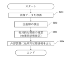
- FIG. 4A is a flowchart showing the flow of the vehicle state estimation process by the vehicle state estimation device 10.
- the vehicle state estimation process is performed by the CPU 11 reading the vehicle state estimation program from the ROM 12 or the storage 14, expanding the program into the RAM 13 and executing the program.
- the CPU 11 acquires the image data captured by the camera 20 (step S101).
- step S101 the CPU 11 estimates the relative relationship between the own vehicle and another vehicle using the image data acquired from the camera 20 (step S102). The process of step S102 will be described in detail later.
- step S102 the CPU 11 outputs the relative relationship between the own vehicle and the other vehicle to the external device (step S103).
- FIG. 5 is a diagram for showing an example in this embodiment.
- the own vehicle 1 is the second lane from the left and the other vehicle 2 is from the left on a road having two lanes on each side, a side road, and a total of four lanes for going up and down. It is assumed that you are driving in the first lane.
- Reference numeral 41 is a median strip
- reference numerals 42a to 42d are lane marking lines
- reference numeral 43 is a curb
- reference numeral 44 is a boundary between a sidewalk and a building.
- the median strip 41 is an example of a lane marking.
- FIG. 8A is a flowchart showing the details of the process shown in step S102 of FIG. 4A.
- the CPU 11 acquires image data from the camera 20 (step S121).
- the CPU 11 uses the image data acquired from the camera 20 to detect the area where the other vehicle existing in the image data is imaged (step S122), and the other vehicle existing in the image data is imaged. Clarify the area on the image data. As described above, this region may be a rectangle including other vehicles.
- FIG. 9A is a diagram showing an example in which a rectangle 52 including a region in which another vehicle is imaged is detected from a certain image data.
- an algorithm for detecting the subject captured in an arbitrary image may be used, or a neural network such as CNN (Convolutional Neural Network, convolutional neural network) may be used. You may use it. Specifically, it may be detected using YOLO (You Look Only Once) (see https://arxiv.org/abs/1612.08242 and the like).
- YOLO You Look Only Once
- FIG. 9A the case where one other vehicle 2 exists in the image data is illustrated, but when a plurality of other vehicles 2 are imaged, the CPU 11 determines the area where the other vehicle 2 is imaged. It is detected for each other vehicle 2.
- the CPU 11 When estimating the traveling direction of another vehicle, the CPU 11 detects a pair of front wheels and rear wheels existing on one side of the vehicle body of the other vehicle from the image data. Further, the CPU 11 obtains the coordinates on the image regarding the detected lowermost portions of the front wheels and the rear wheels.
- the coordinates related to the lowermost portion are for acquiring the ground contact points of the front wheels and the rear wheels, but may be any two points in the area where the other vehicle is imaged. The reason why the coordinates at the bottom of the front wheels and the rear wheels are preferable will be explained.
- the tires of a general automobile are in contact with the road, and the ground contact points of the front wheels and the ground contact points of the rear wheels are almost in a straight line.
- the condition that the two points should be satisfied is that the line connecting the two points is almost horizontal to the road as in the side step.
- the CPU 11 selects two points close to the ground contact surface according to the ground clearance of the imaged camera 20 and the vehicle height of the other vehicle 2, or divides the shape of the other vehicle 2 into two on the left and right. You may choose the point where you can get. In this case, if the difference between the ground clearance of the camera 20 and the vehicle height of the other vehicle 2 is equal to or greater than a predetermined threshold value, the CPU 11 can obtain a line that divides the area of the other vehicle 2 into two on the left and right.
- the horizontal relationship with respect to the road will be described with reference to FIG.
- the line segment connecting the point 62a and the point 62b on the opposite side of the ground contact surface with respect to the center of the tire has a horizontal relationship with respect to the road, and the line segment connecting the point 62a and the point 62c near the door knob is horizontal with respect to the road. It's not a relationship.
- the horizontal relationship is a line segment whose height in the real space hardly changes with respect to the lowermost surface of the car.
- FIG. 10 is a diagram showing the coordinates of the lowermost portions of the front wheels and the rear wheels existing on one side of the vehicle body of the other vehicle 2.
- the CPU 11 obtains the coordinates of the lowest portion of the rear wheels of the other vehicle 2 (x c1 , y c1 ) and the coordinates of the lowest portion of the front wheels of the other vehicle 2 (x c2 , y c2 ).
- the front wheels and the rear wheels of the other vehicle 2 may also be detected inside the circumscribed rectangle 52 of the other vehicle 2 by using an object detection algorithm such as YOLO.
- the CPU 11 obtains the coordinates of the lowermost portions of the front wheels and the rear wheels existing on one side of the vehicle body of the other vehicle 2, the CPU 11 obtains the angle formed by the line segment passing through the obtained coordinates and the horizontal line 61 in the image data 50.
- the line segment obtained here is a line segment connecting at least two points in the region where the other vehicle is imaged, for example, a line segment connecting the points forming the region where the two tires of the vehicle are in contact with the ground.
- the horizon will be described.
- the horizontal line is a virtual line segment that is not photographed, and the y coordinate is fixed when the image is regarded as an xy plane, and the line segment passes through two arbitrary x coordinate points.
- An example is shown as a horizontal line 61 in FIG. It is assumed that the camera is installed so that it is horizontal to the road, but if the camera is not horizontal to the road, the image itself will be horizontal to the road. May be corrected.
- FIG. 11 is a diagram showing an example of image data 50.
- the angle ⁇ c1 shown in FIG. 11 is an example of the angle formed by the line segment and the horizontal line 61 related to the other vehicle 2 located on the left side with respect to the own vehicle 1. That is, FIG. 11 is a diagram for explaining an angle composed of a line segment passing through the coordinates of the lowermost portions of the front wheels and the rear wheels existing on one side of the vehicle body of the other vehicle 2 and the horizontal line 61.
- the angle ⁇ c formed by the line segment 53 passing through the coordinates (x c1 , y c1 ) and (x c2 , y c2 ) and the horizontal line 61 is calculated by the following formula.
- ⁇ c arctan ⁇ (y c2- y c1 ) / (x c2- x c1 ) ⁇
- CPU11 is the size of the obtained angle phi c, can be another vehicle relative to the own vehicle 1 is what is located left or right, to estimate whether and how much apart. That is, in the CPU 11, if ⁇ c is equal to or less than the predetermined first threshold value, the other vehicle 2 is on the left side of the own vehicle 1, and if ⁇ c is equal to or more than the predetermined first threshold value, the other vehicle 2 is the own vehicle 1. It can be estimated to be located on the right side. Further, the CPU 11 may estimate the distance between the own vehicle 1 and the other vehicle 2 based on the size of the difference between the first threshold value and ⁇ c. The distance referred to here is a lateral distance with respect to the own vehicle.
- the CPU 11 increases the distance between the own vehicle 1 and the other vehicle 2 as the difference between the first threshold value and ⁇ c becomes smaller. It may be presumed that it is.
- ⁇ c is equal to or greater than the first threshold value, that is, when the other vehicle 2 is located on the right side, it is estimated that the greater the difference between the first threshold value and ⁇ c , the greater the distance between the own vehicle and the other vehicle. May be good.
- ⁇ c is an angle less than 90 degrees such as 20 degrees and 47 degrees, it may be estimated that the other vehicle 2 is located on the left side of the own vehicle 1.
- ⁇ c1 of 47 degrees is selected among the other vehicle 2 that has acquired ⁇ c2 of 20 degrees and the other vehicle that has acquired ⁇ c1 of 47 degrees. It may be estimated that the acquired other vehicle 2 is located closer to the own vehicle 1. If ⁇ c3 is 165 degrees or the like, it may be estimated that the other vehicle 2 is located on the right side of the own vehicle 1.
- the CPU 11 estimates how far the other vehicle 2 is traveling from the lane in which the own vehicle 1 is traveling, according to the estimated position of the other vehicle 2 and the distance from the own vehicle 1. May be good. As described in the second embodiment described later, when the center line of the road is known or given, the CPU 11 determines whether the other vehicle 2 is traveling in the same direction as the own vehicle 1 or vice versa depending on the size of ⁇ c. You may estimate whether you are traveling in the direction. Needless to say, it is not necessary to use the central line of the road in the first embodiment.
- the vehicle state estimation device 10 estimates the relative relationship with the other vehicle 2 by using the image captured from the own vehicle 1. Since only the image is used and a high amount of calculation is not required, the processing may be executed only by the DSP (Digital Signal Processor) mounted on the own vehicle 1. When the processing is executed by the DSP mounted on the own vehicle 1, there is no need for communication, and therefore the communication amount of the own vehicle 1 can be reduced. Further, when aggregating to a server or performing a process of estimating a relative relationship with another vehicle 2 at distributed edges, the minimum data required is only the angle ⁇ c , so the amount of communication is also the same. Can be reduced. Further, since the information such as the lane marking is not used, the vehicle state estimation device 10 can estimate the relative relationship between the own vehicle 1 and the other vehicle 2 even on the road where the lane marking does not exist.
- the DSP Digital Signal Processor
- the vehicle state estimation device 10 uses an image captured by a camera that captures the road, such as a camera installed on the roadside instead of the own vehicle 1, and is relative to the camera and another vehicle. Relationship may be estimated.
- the other vehicle in addition to the relative position relationship between the own vehicle and the other vehicle estimated in the first embodiment, the other vehicle is traveling based on the lane in which the own vehicle is traveling. Estimate the lane in which you are, that is, the relative lane relationship between your vehicle and other vehicles.
- the marking line is detected from the image. That is, by detecting the lane marking, which is the boundary of the lane, from the image captured by the camera mounted on the own vehicle and using it together with the angle ⁇ c obtained in the first embodiment, the own vehicle and another vehicle can be used. Estimate the relative lane relationship of.
- FIG. 3B is a block diagram showing an example of the functional configuration of the vehicle state estimation device 10 according to the second embodiment. The explanation will be given with reference to FIG. 3B, focusing on the differences from the first embodiment.
- the vehicle state estimation device 10 is first implemented at a point where the road information storage unit 131 is added to the storage unit 130 and a point where the lane marking unit 142 is added to the other vehicle state estimation unit 140. Different from the form.
- the lane marking unit 142 detects a range corresponding to the lane marking from the image data received from the image acquisition unit 141. Information relating to the range corresponding to the detected lane marking line may be stored in the road information storage unit 131.
- the lane marking unit 142 sends information in the range corresponding to the lane marking in the image data to the other vehicle state estimation unit 144.
- the information in the range corresponding to the lane marking may be, for example, the coordinates of the four or two ends of the lane marking.
- the lane marking detection unit 142 obtains a line segment from the coordinates of the two ends of the dotted line of each lane marking.
- the lane marking detection unit 142 extends the obtained line segment and uniquely treats the obtained line segment as a lane marking representing the same lane when the positional relationship and the angle are close. Then, the lane marking detection unit 142 may use the coordinates having the largest Y coordinate value and the coordinates having the smallest Y coordinate value as the information in the range corresponding to the lane marking. Further, the lane marking detection unit 142 may connect a plurality of dotted lines to form one lane marking.
- the lane marking unit 142 may perform a process of correcting an area erroneously detected as a lane marking or an area erroneously detected as a non-lane marking line due to dirt in the lane marking line or wear of the lane marking line by a scale conversion process or the like. good.
- the lane marking detection unit 142 may determine whether or not the lane marking is erroneously detected as a non-lane marking based on, for example, the result of machine learning. Further, the lane marking detection unit 142 may perform edge extraction processing by using an edge extraction filter. Further, the lane marking unit 142 may perform a straight line detection process by Hough transform.
- the lane marking detection unit 142 may extract only lane markings (for example, road center line, lane boundary line, lane outside line, etc.) indicating the extension direction of the lane due to differences in shape, color, and the like. Then, the lane marking detection unit 142 sets a lane marking other than the extracted lane marking (approach of road obstacles, lane marking indicating fluid guide, etc.) and a part of road markings (maximum speed, traffic classification according to traveling direction, etc.). The process of excluding from the extraction target may be performed. In some cases, the lane markings have disappeared, and in other cases, the lane markings have not been drawn on the road.
- lane markings for example, road center line, lane boundary line, lane outside line, etc.
- the estimated target vehicle can be in which lane by using only the absolute position such as the latitude and longitude of the own vehicle and the relative position between the own vehicle and the estimated target vehicle. This is because it may be possible to estimate whether the vehicle is running. Further, since the number of lanes on the road on which the estimation target vehicle is traveling is the number of lanes on the road on which the own vehicle 1 is traveling, the number of lanes on the road on which the estimation target vehicle is traveling is acquired as additional information. It does not have to be done.
- FIG. 4B is a flowchart showing the flow of the vehicle state estimation process by the vehicle state estimation device 10.
- the vehicle state estimation process is performed by the CPU 11 reading the vehicle state estimation program from the ROM 12 or the storage 14, expanding the program into the RAM 13 and executing the program.
- the second embodiment is different from the first embodiment in that the lane markings are detected and the lane markings detected in the estimation of the relative relationship are used.
- the CPU 11 acquires the image data captured by the camera 20 (step S201).
- the CPU 11 detects the lane marking line using the image data acquired from the camera 20 (step S202).
- the CPU 11 detects a region in which the lane markings are captured in the image data acquired from the camera 20.
- a white line recognition system see IPSJ 69th National Convention, "Development of white line recognition system for automobile camera moving images", etc.
- YOLO machine learning, etc. May be used.
- the CPU 11 acquires the angle ⁇ c formed by the line segment connecting the coordinates of the lowermost portions of the front wheels and the rear wheels existing on one side of the vehicle body of the other vehicle and the horizontal line 61. Further, the CPU 11 records whether the detected division line is on the left side or the right side with respect to the center line. When the CPU 11 detects a plurality of lane markings on the left side and / or the right side, the CPU 11 may calculate the number of lane markings from the center line for each lane marking with reference to the center line.
- the CPU 11 When the area corresponding to the lane marking is detected, the CPU 11 also obtains an angle including the horizon 61 in the image data 50 and the region corresponding to the lane marking for the lane markings 42a to 42d in FIG. 9A.
- the angle formed by the horizontal line 61 in the image data 50 is obtained for the lane markings 42a and 42b that define the lane in which the other vehicle 2 is traveling.
- the CPU 11 obtains the coordinates of two arbitrary points for the division lines 42a and 42b, respectively.
- the coordinates of the two points of the lane marking 42a are (x 11 , y 11 ) and (x 12 , y 12 ), and the coordinates of the two points of the lane marking 42b are (x 21 , y 21 ) and (x 22 , y 22 ). do.
- the CPU 11 calculates the angles ⁇ 1 and ⁇ 2 of the line segments passing through the arbitrary two points of the lane markings 42a and 42b by the following formulas.
- ⁇ 1 arctan ⁇ (y 12- y 11 ) / (x 12- x 11 ) ⁇
- ⁇ 2 arctan ⁇ (y 22- y 21 ) / (x 22- x 21 ) ⁇
- the CPU 11 includes an angle ⁇ c between a line segment 53 connecting the lowest coordinates of the front wheels and rear wheels existing on one side of the vehicle body of another vehicle and a horizontal line 61, and a region corresponding to the horizontal line 61 and lane markings 42a and 42b.
- the relative relationship is estimated using the angles ⁇ 1 and ⁇ 2. In the example of FIG. 9B, the relationship of ⁇ 1 ⁇ c ⁇ ⁇ 2 is established.
- the CPU 11 can presume that the other vehicle 2 is traveling in the lane sandwiched between the lane markings 42a and the lane markings 42b.
- the lane marking 42b is the first lane marking on the left side with respect to the center line 51. Therefore, the CPU 11 can estimate that the other vehicle 2 is traveling in the left lane with reference to the lane in which the own vehicle is traveling.
- angle phi 2 consisting of angle phi 1
- partition lines 42b and the horizontal line 61. consisting division line 42a and the horizontal line 61.
- Figure 9B the disclosure of It is not something that is done.
- the CPU 11 calculates an angle consisting of the horizon 61 for all of the lane markings detected by the lane marking detection unit 142, and compares the angle with the angle ⁇ c to compare with the angle ⁇ c, so that the other vehicle is based on the lane in which the own vehicle is traveling. It goes without saying that the relative relationship with the lane in which the vehicle travels may be estimated.
- the CPU 11 calculates an angle consisting of the horizontal line 61 for all the lane markings detected by the lane marking detection unit 142, and determines the angle ⁇ c with the angle consisting of the lane marking and the horizontal line as a threshold value. Therefore, it goes without saying that the relative relationship with the lane in which the other vehicle travels may be estimated based on the lane in which the own vehicle travels. That is, when the angles formed by the lane markings 41, 42c, 42d and the horizontal line 61 are ⁇ 3 , ⁇ 4 , and ⁇ 5 , respectively, if the CPU 11 has ⁇ 1 ⁇ ⁇ c ⁇ ⁇ 2 , the other vehicle is larger than the own vehicle.
- the CPU 11 may presume that the other vehicle 2 is traveling in the same lane as the own vehicle 1. Further, even when the other vehicle 2 is detected near the center line 51 of the image 50, the CPU 11 may presume that the other vehicle 2 is traveling in the same lane as the own vehicle 1. Further, if ⁇ 3 ⁇ ⁇ c ⁇ ⁇ 4 , the CPU 11 can estimate that the other vehicle 2 is traveling in the lane to the right of the own vehicle 1.
- the other vehicle state estimation unit 140 has a function of detecting that the lane marking 41 is the center line on the roadway , if ⁇ 3 ⁇ ⁇ c , the CPU 11 and the other vehicle 2 own themselves. It may be estimated that the vehicle is traveling in the opposite direction to the vehicle 1.
- the CPU 11 estimates the traveling lane of the other vehicle 2 based on the horizontal angle of the line segment 53 and the lane marking, but the CPU 11 may estimate the traveling lane of the other vehicle 2 based on the inclination of the line segment 53 and the lane marking. good. That is, the slope of the line segment 53 (y c2- y c1 ) / (x c2- x c1 ) is the slope of the lane marking 42a (y 12- y 11 ) / (x 12- x 11 ) and the lane marking 42b. If it is between the inclination (y 22- y 21 ) / (x 22- x 21 ), the CPU 11 may presume that the other vehicle 2 exists between the lane markings 42a and 42b.
- FIG. 12 is a diagram showing an example of image data 50. From the image data 50, the CPU 11 is a line segment with respect to the distance between the coordinates (x 11 , y 11 ) and (x 23 , y 23 ) on the left and right lane markings of the lane in which the other vehicle 2 is traveling. Find the difference or ratio of the distance between the coordinates (x c3, y c3 ) on 53 and (x 23 , y 23). By obtaining the difference or ratio, the CPU 11 can estimate how much margin the other vehicle 2 is traveling from the lane marking. In the example shown in FIG. 12, the CPU 11 can estimate from the above difference or ratio that the other vehicle 2 is traveling closer to the sidewalk side.
- the CPU 11 may estimate the traveling direction in which the other vehicle is traveling as the state of the other vehicle. Specifically, the CPU 11 may estimate the traveling direction of the other vehicle by recognizing the front or the back of the other vehicle from the image data.
- the CPU 11 determines whether or not the other vehicle 2 and the other vehicle 3 include parts existing on the back surface of the vehicle such as a tail lamp, a brake lamp, or a reflector portion by using an object recognition algorithm such as YOLO.
- the CPU 11 estimates whether the other vehicles 2 and 3 are facing the front or the back depending on whether or not the parts existing on the back of the vehicle are included. Further, the CPU 11 can estimate the traveling directions of the other vehicles 2 and 3 by using the estimation result of the front or the back in addition to the calculated line segment.
- the CPU 11 may estimate the traveling speed difference between the other vehicle and the own vehicle as the state of the other vehicle from two or more image data. Specifically, the CPU 11 can estimate the difference in traveling speed from the other vehicle as the state of the other vehicle from the image data captured at a plurality of times.
- the CPU 11 from the image data 50a at time t-n, the bottom of the coordinates of the rear wheel of the other vehicle 2 (x c1, y c1) obtaining a t-n. Similarly, the CPU 11 obtains the coordinates (x c1 , y c1 ) t of the lowermost part of the rear wheel of the other vehicle 2 from the image data 50b at the time t. Then, the CPU 11 calculates the movement vector of the lowermost part of the rear wheel of the other vehicle 2 between the two image data. The CPU 11 further acquires the speed of the own vehicle 1 from OBD (On-board diagnostics) or the like.
- OBD On-board diagnostics
- the CPU 11 can calculate the difference in traveling speed of the other vehicle 2 from the own vehicle 1 from the speed of the own vehicle 1 and the movement vector of the lowermost portion of the rear wheels of the other vehicle 2. Further, when the traveling speed of the own vehicle is used as a parameter related to the own vehicle as in the third embodiment described later, the traveling speed of the other vehicle is estimated by taking the sum of the traveling speed difference and the traveling speed of the own vehicle. You can also do it.
- the own vehicle and others at the time when the image is captured such as GPS coordinates or the traveling speed of the own vehicle.
- the parameters related to the own vehicle are, for example, the traveling speed of the own vehicle or the position information.
- FIG. 1B is a diagram showing a schematic configuration of a vehicle state estimation system including the vehicle state estimation device according to the third embodiment of the present disclosure.
- the vehicle state estimation system according to the third embodiment of the present disclosure is first implemented in that the vehicle state estimation device 10, the camera 20, and the GPS sensor 30 are mounted on the own vehicle 1. It differs from the embodiment and the second embodiment.
- the vehicle state estimation device 10 is a device that estimates the state of another vehicle based on the image captured by the camera 20 and the information output from the GPS sensor 30. For example, the state of a vehicle (other vehicle) other than the own vehicle 1 is estimated.
- the other vehicle is an example of the subject imaged in the same manner as in the first embodiment and the second embodiment, and may be a structure such as a signboard, a road sign, or a feature adjacent to the road.
- the vehicle state estimation device 10 uses the image data obtained by imaging the range including the road area in the traveling direction in which the own vehicle 1 is traveling and the position where the image data obtained by the GPS sensor 30 is captured. As the state of the other vehicle, at least one of the lane in which the other vehicle is traveling, the direction in which the other vehicle is traveling, and the speed in which the other vehicle is traveling is estimated.
- the GPS sensor 30 calculates the latitude and longitude of the own vehicle 1 on which the GPS sensor 30 is mounted by receiving GPS signals transmitted by a plurality of GPS satellites and performing a ranging calculation.
- the GPS sensor 30 outputs the calculated latitude and longitude to the vehicle state estimation device 10 as position data of the own vehicle 1. If the same function as the GPS sensor 30 is exhibited instead of the GPS sensor 30, the present disclosure uses a ground (road) -based position identification system (Ground Based Positioning System: GBPS) or the like. You may.
- GBPS Ground Based Positioning System
- FIG. 3C is a block diagram showing an example of the functional configuration of the vehicle state estimation device 10 according to the third embodiment. The explanation will be given with reference to FIG. 3C, focusing on the differences from the first embodiment and the second embodiment.
- the vehicle state estimation device 10 according to the third embodiment is different from the first embodiment and the second embodiment in that the own vehicle traveling lane estimation unit 120 is added.
- the input / output I / F 110 receives the image captured by the camera 20 and the data output from the GPS sensor 30, and supplies the received data to the own vehicle traveling lane estimation unit 120 and the other vehicle state estimation unit 140. .. Further, the input / output I / F 110 may output data representing the estimation result of the state of the other vehicle output from the other vehicle state estimation unit 140 to an external device (not shown).
- the external device may be, for example, a display or a speaker mounted on the own vehicle 1. Further, the input / output I / F 110 may be transmitted to a server existing outside the own vehicle or a vehicle other than the own vehicle by using a communication unit (not shown).
- the own vehicle traveling lane estimation unit 120 estimates the lane in which the own vehicle 1 is traveling.
- the own vehicle traveling lane estimation unit 120 includes an own vehicle traveling lane estimation unit 121.
- the own vehicle traveling lane estimation unit 121 acquires the latitude and longitude information of the own vehicle 1 transmitted from the GPS sensor 30. Further, the own vehicle traveling lane estimation unit 121 acquires information representing the road configuration corresponding to the latitude and longitude from the road information storage unit 131. Then, the own vehicle traveling lane estimation unit 121 estimates the lane in which the own vehicle 1 travels by using the acquired latitude and longitude information and the information representing the configuration of the corresponding road.
- the own vehicle traveling lane estimation unit 121 may perform the latitude. And the longitude information may be corrected.
- the own vehicle traveling lane estimation unit 121 may correct the latitude and longitude information by, for example, map matching processing, the traveling locus of the own vehicle 1, analysis of image data acquired from the camera 20 and the like. Then, the own vehicle traveling lane estimation unit 121 may estimate the lane in which the own vehicle 1 travels after correcting the latitude and longitude information.
- Information on the lane in which the own vehicle is traveling may be acquired from the outside. The outside may be acquired from, for example, another vehicle other than the other vehicle imaged by the camera mounted on the own vehicle, a camera arranged on the roadside, or the like.
- the storage unit 130 is provided in, for example, the ROM 12 or the storage 14.
- the storage unit 130 includes a road information storage unit 131 and each vehicle state storage unit 132.
- information representing the configuration of the road corresponding to the position may be stored in advance in association with the position data represented by the latitude and longitude.
- the information representing the road composition for example, the number of lanes in each of the up and down directions, the number of lane markings and lane markings, the type, and the shape are expressed by latitude and longitude information or a latitude and longitude substitution system. Information may be included.
- the information representing the composition of the road includes information expressing the presence / absence of sidewalks, shoulders, sidewalks and medians strips, and their widths in latitude and longitude information or latitude and longitude substitution systems. May be good.
- each vehicle state storage unit 132 stores, for example, the relative relationship between the own vehicle and the other vehicle estimated by the first embodiment or the second embodiment together with the time when the state of the relationship is estimated. good.
- the other vehicle state estimation unit 144 uses the relative relationship between the own vehicle and the other vehicle obtained by the first embodiment or the second embodiment and the lane in which the own vehicle is traveling to allow the other vehicle to move. Estimate the lane in which you are driving. The case where the relative relationship between the own vehicle and the other vehicle is the lane in which the other vehicle is traveling based on the lane in which the own vehicle is traveling is described. It is estimated that another vehicle is in the lane to the left of the lane in which the own vehicle is driving, and it is estimated that the own vehicle is in the third lane (assuming that it is in the rightmost lane). If this is the case, the other vehicle state estimation unit 144 can estimate that the other vehicle is traveling in the lane to the left of the third lane, so that the other vehicle is traveling in the second lane. presume.
- the vehicle state estimation process is performed by the CPU 11 reading the vehicle state estimation program from the ROM 12 or the storage 14, expanding the program into the RAM 13 and executing the program.
- the CPU 11 acquires the GPS data acquired by the GPS sensor 30 and the image data captured by the camera 20 (step S301).
- step S301 the CPU 11 estimates the traveling lane of the own vehicle using the GPS data acquired from the GPS sensor 30 (step S302).
- the own vehicle traveling lane estimation process in step S302 will be described in detail later.
- step S302 the CPU 11 estimates the relative relationship between the own vehicle and the other vehicle and the state of the other vehicle using the image data acquired from the camera 20 (step S303). Since the process of S303 is the same as that of the first embodiment and the second embodiment, detailed description of the process is omitted.
- the CPU 11 may use the estimation result of the traveling lane of the own vehicle as necessary when estimating the state of another vehicle.
- the CPU 11 outputs the other vehicle state information, which is the information on the state of the other vehicle, obtained by estimating the relative relationship between the own vehicle and the other vehicle and the state of the other vehicle to the external device ( Step S304).
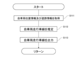
- the CPU 11 acquires the own vehicle position information representing the position information of the own vehicle 1 and the road information of the road on which the own vehicle 1 is traveling (step S111).
- the own vehicle position information is GPS data (N c , E c ).
- (N c , E c ) means that it is a set of latitude and longitude of the own vehicle 1.
- the CPU 11 acquires road information from the road information storage unit 131.
- step S111 the CPU 11 estimates the traveling lane of the own vehicle 1 based on the own vehicle position information and the road information (step S112).
- step S112 the CPU 11 outputs information on the traveling lane of the own vehicle 1 to each vehicle state storage unit 132 (step S113).
- FIG. 7 is a diagram for explaining the own vehicle traveling lane estimation process.
- the CPU 11 acquires information on the number of lanes related to the road on which the own vehicle 1 is traveling from the road information storage unit 131. Further, the CPU 11 acquires GPS data (N 01 , E 01 ) to (N 42 , E 42 ) of each section line constituting each lane. (N 01 , E 01 ) to (N 42 , E 42 ) mean that they are a set of latitude and longitude, respectively.
- the CPU 11 may correct the position information using the ground information. Further, the CPU 11 may correct the position information depending on how the surrounding buildings, road signs, traffic lights, roads in front, etc. are reflected in the camera 20.
- the median strip and the lane marking line are assumed to be solid lines, but the median strip or the lane marking line may be a broken line.
- the CPU 11 may additionally perform processing such as connecting the broken lines to each other and regarding the lane marking line as one solid line.
- the CPU 11 may use GPS data indicating the positions of those objects.
- the position information of virtual center lines at both left and right ends of the road may be used as temporary GPS data.
- the CPU 11 calculates the change in the distance between the own vehicle and the other vehicle as a relative relationship between the own vehicle and the other vehicle. Since the specific calculation method is described in the second embodiment, it will be omitted.
- the CPU 11 uses the difference in the time between the two images captured for calculating the change in the distance between the own vehicle and the other vehicle and the change in the distance to increase the speed between the own vehicle and the other vehicle. Calculate the difference. Then, the CPU 11 can estimate the speed at which the other vehicle is traveling by taking the sum of the speed of the own vehicle obtained as an external parameter and the calculated speed difference.
- the CPU 11 may calculate the distance from the lane marking of another vehicle after converting it into latitude and longitude information in real space instead of using the coordinates on the image data. Further, the CPU 11 may calculate the distance of another vehicle from the lane marking as a specific numerical value by using the width information between the lane markings acquired from the road network data, the dynamic map, or the like. Further, the CPU 11 may calculate the distance of another vehicle from the lane marking after converting the image so that the angle of each lane marking and the line segment from the horizontal becomes 90 degrees by affine transformation.
- FIG. 8B is a flowchart showing the details of the other vehicle state estimation process shown in step S303 of FIG. 4C.
- the CPU 11 acquires image data from the camera 20 (step S321). In parallel with the acquisition of the image data from the camera 20, the CPU 11 acquires the information on the traveling lane of the own vehicle 1 from each vehicle state storage unit 132 (step S322). In the present embodiment, the CPU 11 acquires the own vehicle traveling lane information that the own vehicle 1 is traveling in the second lane from the left from FIG. 7.
- the CPU 11 uses the image data acquired from the camera 20, the CPU 11 detects another vehicle existing in the image data (step S323) and also detects a lane marking existing in the image data (step S324).
- the CPU 11 reveals areas on the image data of other vehicles and lane markings existing in the image data.
- FIG. 9A is a diagram showing an example in which another vehicle and a lane marking are detected from a certain image data.
- the CPU 11 grasps the number of the median strip 41 and the division lines 42a to 42d in the image data 50 shown in FIG. 9 on the left or right side of the center line 51 of the image data 50.
- the lane marking 42b is the first presence on the left when viewed from the center line 51
- the lane marking 42a is the second presence on the left when viewed from the center line 51. Therefore, the own vehicle traveling lane is between the lane marking 42b and the median strip 41.
- the CPU 11 detects the other vehicle 2 and the circumscribing rectangle 52 relating to the shape of the other vehicle 2 from the image data 50 shown in FIG. 9A.
- the CPU 11 may detect it by using an object detection algorithm such as YOLO, for example.
- an object detection algorithm such as YOLO, for example.
- the CPU 11 detects the area in which the other vehicle 2 is imaged for each other vehicle 2.
- the CPU 11 uses, for example, a white line recognition system (see IPSJ 69th National Convention, "Development of a white line recognition system for moving images of automobile cameras", etc.) when detecting a lane marking in image data.
- a white line recognition system see IPSJ 69th National Convention, "Development of a white line recognition system for moving images of automobile cameras", etc.
- the above-mentioned YOLO, machine learning, or the like may be used.
- the CPU 11 acquires information on the traveling lane of the own vehicle, detects another vehicle and a lane marking, and then estimates the state of the detected other vehicle (step S325).
- the CPU 11 estimates, for example, the traveling direction, the traveling lane, or the speed of the other vehicle as the state of the other vehicle.
- the method of estimating the state of the other vehicle is the same as that of the first embodiment or the second embodiment.
- the CPU 11 obtains an angle from the horizontal in the image data 50 with respect to the median strip 41 and the division lines 42a to 42d.
- the method of obtaining the angle from the horizontal in the image data 50 is the same as that in the second embodiment.
- step S325 the CPU 11 inputs the detected other vehicle state information, which is the detected other vehicle state information, into each vehicle state storage unit 132 (step S326).
- step S326 the CPU 11 outputs other vehicle status information to the external device (step S327).
- the CPU 11 can estimate the state of the other vehicle existing around the own vehicle based on the image data and the GPS data without communicating with the other vehicle. ..
- the CPU 11 may estimate the distance from the lane marking in the lane in which the other vehicle is traveling as the state of the other vehicle from the image data. By estimating the distance of the other vehicle from the lane marking, the CPU 11 can estimate how much margin the other vehicle 2 is traveling from the lane marking.
- the CPU 11 determines whether the other vehicle is parked or stopped based on, for example, the distance between the other vehicle and each lane marking and the speed of the other vehicle. You can also estimate whether or not.
- the CPU 11 acquires information such as the traveling direction of the own vehicle and the number of lanes in the opposite direction from the road network in addition to the lane in which the other vehicle is moving and the traveling direction of the other vehicle, so that the other vehicle travels in the reverse direction. It is also possible to estimate whether or not the vehicle is running.
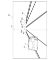
- FIG. 13 is a diagram showing how the vehicle state estimation device 10 having a camera at the position of the sidewalk captures an image of a range including a road area. As shown in FIG. 13, even if the camera is on the sidewalk, the vehicle state estimation device 10 does not necessarily have to be mounted inside the vehicle as long as it can image a range including the road area.
- the vehicle The state estimation device 10 can apply the process according to the present embodiment. Further, the vehicle state estimation device 10 recognizes the "road area" in the image data by using, for example, a semantic segmentation technique (eg, http: // mi.eng.cam.ac.uk/projects/segment/). If the vehicle exists outside the range of the "road area", it may be presumed that the vehicle is parked or stopped in a parking lot or the like regardless of the orientation of other vehicles.
- a semantic segmentation technique eg, http: // mi.eng.cam.ac.uk/projects/segment/
- FIG. 14 is a diagram showing an example of image data.
- image data 50 shown in FIG. 14 other vehicles 2 and 4 facing in the lateral direction are shown. It is assumed that the other vehicle 2 is traveling on the road, but the other vehicle 4 is parked or stopped in a parking lot beside the road, not on the road.
- the CPU 11 determines the state of the vehicle by calculating the coordinates of the lowermost portions of the front wheels and the rear wheels of the vehicle and the line segments connecting the coordinates. Can be estimated. In the example of the image of FIG. 14, the CPU 11 can estimate that the other vehicle 2 is traveling in a direction orthogonal to the traveling direction of the own vehicle 1. Further, in the example of the image of FIG. 14, the CPU 11 can presume that the other vehicle 4 is parked or stopped because the other vehicle 4 is not on the road.
- the vehicle state estimation device 10 uses the two coordinates of the front wheels and the rear wheels of the other vehicle, but the present disclosure is not limited to this.
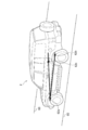
- 15 to 18 are views showing a special vehicle. Even when a special vehicle as shown in FIGS. 15 to 18 is shown in the image data, the vehicle state estimation device 10 can estimate the state of the vehicle by obtaining the coordinates of the vehicle.
- the vehicle state estimation device 10 may use the coordinates of all or part of the three or more wheels. Further, the vehicle state estimation device 10 may use the coordinates of the two wheels if the vehicle travels on only two wheels, such as a motorcycle. Further, for example, in the case of the vehicle shown in FIG. 16 in which a spare tire is mounted on the back surface of the vehicle, the vehicle state estimation device 10 may recognize the back surface and ignore the spare tire on the back surface. good.
- the vehicle state estimation device 10 defines that the shape of the wheel is not only a circle but also a substantially triangular one having an arc-shaped apex, and then the front wheel. And the rear wheels may be recognized from the image data.
- the vehicle state estimation device 10 is a "tricycle" so as to label the vehicle or motorcycle when the vehicle is detected by YOLO or the like. The process may be different from that for two-wheeled vehicles and four-wheeled vehicles. Then, when the vehicle state estimation device 10 detects that the vehicle is a tricycle, it may acquire a plurality of feature points of the rear wheels, calculate the inclination between the feature points, and use the calculated inclination for estimating the state. Further, in the case of a three-wheeled vehicle, the vehicle state estimation device 10 may further detect a side step of the vehicle or a shadow cast by the vehicle on the ground surface instead of the wheels, and use the detected coordinates.
- various processors other than the CPU may execute the vehicle state estimation process executed by the CPU reading the software (program) in each of the above embodiments.
- the processors include PLD (Programmable Logic Device) whose circuit configuration can be changed after manufacturing FPGA (Field-Programmable Gate Array), and ASIC (Application Specific Integrated Circuit) for executing ASIC (Application Special Integrated Circuit).
- An example is a dedicated electric circuit or the like, which is a processor having a circuit configuration designed exclusively for the purpose.
- the vehicle state estimation process may be executed by one of these various processors, or a combination of two or more processors of the same type or different types (for example, a plurality of FPGAs, and a CPU and an FPGA). It may be executed by combination etc.).
- the hardware structure of these various processors is, more specifically, an electric circuit in which circuit elements such as semiconductor elements are combined.
- the program is a non-temporary storage medium such as a CD-ROM (Compact Disk Read Only Memory), a DVD-ROM (Digital entirely Disk Online Memory), and a USB (Universal Serial Bus) memory. It may be provided in the form. Further, the program may be downloaded from an external device via a network.
- a vehicle state estimation device that estimates the position or state of a vehicle. Memory and With at least one processor connected to the memory Including The processor Get an image that includes the vehicle you want to estimate The position of the target vehicle to be estimated based on the image pickup device that captured the image using a line segment connecting at least two points selected from the region where the vehicle to be estimated is imaged in the image. Or a vehicle condition estimator configured to estimate the condition.
- a non-temporary storage medium that stores a program that can be executed by a computer to execute a vehicle state estimation process that estimates the position or state of a vehicle.
- the vehicle state estimation process is Get an image that includes the vehicle you want to estimate The position of the target vehicle to be estimated based on the image pickup device that captured the image using a line segment connecting at least two points selected from the region where the vehicle to be estimated is imaged in the image. Or estimate the state, Non-temporary storage medium.
Abstract
This vehicle condition estimation method, for estimating the position or condition of a vehicle with an information processing device provided with a processor and memory connected to the processor, involves acquiring an image containing the vehicle to be estimated, using a line segment connecting at least 2 points selected from a region in the aforementioned image where the vehicle to be estimated is shown, and estimating the position or condition of the vehicle to be estimated with reference to the imaging device that captured the image.
Description
開示の技術は、車両状態推定方法、車両状態推定装置、及び車両状態推定プログラムに関する。
The disclosed technology relates to a vehicle state estimation method, a vehicle state estimation device, and a vehicle state estimation program.
近年、例えば、自動車の走行制御又は運転サポートに関する技術の開発が活発に行われている。非特許文献1では、自動車の走行制御又は運転サポートに関する技術に関する報告がなされている。このような技術において、自車両以外の車両(以降、他車両)がどの車線を時速何kmでどちらの方向に走行しているかといった他車両の状態、及び他車両の情報を統合して、車線毎の交通流を正確に認識することは、自車両の走行を安全に制御する上で極めて重要である。
In recent years, for example, the development of technology related to driving control or driving support of automobiles has been actively carried out. Non-Patent Document 1 reports on a technique relating to driving control or driving support of an automobile. In such a technology, the state of the other vehicle such as which lane the vehicle other than the own vehicle (hereinafter referred to as the other vehicle) is traveling at what speed and in which direction, and the information of the other vehicle are integrated into the lane. Accurately recognizing each traffic flow is extremely important for safely controlling the running of the own vehicle.
自動車の走行制御又は運転サポートのためには、自車両の周囲に存在する他車両の状態を認識する必要がある。車々間通信により他車両の状態を認識する技術では、自車両の周囲に存在する他車両が当該技術に対応した機材を搭載している必要があり、機材の普及度合い次第で十分な性能を発揮し得ないという問題がある。さらに、局所的な運転をサポートする目的であれば、自車両と、自車両の周辺に存在する他車両の位置関係を把握できれば十分であり、ネットワークを介したデータの集積及び分析を行うことは必要以上の情報の伝達及び演算を行うことと同義である。
For driving control or driving support of a vehicle, it is necessary to recognize the state of other vehicles existing around the own vehicle. In the technology of recognizing the state of other vehicles by inter-vehicle communication, it is necessary for other vehicles existing around the own vehicle to be equipped with equipment corresponding to the technology, and sufficient performance is exhibited depending on the degree of diffusion of the equipment. There is a problem of not getting it. Furthermore, for the purpose of supporting local driving, it is sufficient to be able to grasp the positional relationship between the own vehicle and other vehicles existing around the own vehicle, and it is not possible to collect and analyze data via the network. It is synonymous with transmitting and calculating more information than necessary.
開示の技術は、上記の点に鑑みてなされたものであり、特殊な機材を用いずに自車両と他車両との関係と、他車両の状態を推定できるようにする車両状態推定方法、車両状態推定装置、及び車両状態推定プログラムを提供することを目的とする。
The disclosed technology was made in view of the above points, and is a vehicle state estimation method and a vehicle that enable the relationship between the own vehicle and another vehicle and the state of the other vehicle to be estimated without using special equipment. It is an object of the present invention to provide a state estimation device and a vehicle state estimation program.
本開示の第1態様は、プロセッサと、当該プロセッサに接続されたメモリとを備える情報処理装置が車両の位置又は状態を推定する車両状態推定方法であって、推定する対象の車両を含む画像を取得し、前記画像における前記推定する対象の車両が撮像されている領域から選択された少なくとも2点を結ぶ線分を用いて、前記画像を撮像した撮像装置を基準とした、前記推定する対象の車両の位置又は状態を推定する。
The first aspect of the present disclosure is a vehicle state estimation method in which an information processing device including a processor and a memory connected to the processor estimates the position or state of a vehicle, and an image including an image to be estimated is displayed. Using a line segment connecting at least two points selected from the region in which the vehicle to be estimated is captured in the image, the estimation target is based on the image pickup device that captured the image. Estimate the position or condition of the vehicle.
本開示の第2態様は、車両の位置又は状態を推定する車両状態推定装置であって、推定する対象の車両を含む画像を取得する画像取得部と、前記画像における前記推定する対象の車両が撮像されている領域から選択された少なくとも2点を結ぶ線分を用いて、前記画像を撮像した撮像装置を基準とした、前記推定する対象の車両の位置又は状態を推定する他車両状態推定部と、を備える。
A second aspect of the present disclosure is a vehicle state estimation device that estimates the position or state of a vehicle, wherein an image acquisition unit that acquires an image including the vehicle to be estimated and the vehicle to be estimated in the image are Another vehicle state estimation unit that estimates the position or state of the target vehicle to be estimated based on the image pickup device that captured the image using a line segment connecting at least two points selected from the imaged region. And.
本開示の第3態様は、コンピュータに車両の位置又は状態を推定させる車両状態推定プログラムであって、コンピュータに、推定する対象の車両を含む画像を取得し、前記画像における前記推定する対象の車両が撮像されている領域から選択された少なくとも2点を結ぶ線分を用いて、前記画像を撮像した撮像装置を基準とした、前記推定する対象の車両の位置又は状態を推定する処理を実行させる。
A third aspect of the present disclosure is a vehicle state estimation program that causes a computer to estimate the position or state of a vehicle, and obtains an image including the vehicle to be estimated by the computer, and the vehicle to be estimated in the image. Using a line segment connecting at least two points selected from the region in which the image is imaged, a process of estimating the position or state of the vehicle to be estimated is executed based on the image pickup device that captured the image. ..
開示の技術によれば、既知の位置から撮像された、推定する対象の車両を含む画像を解析することで、他車両から情報を得ることなく、また特殊な機材を用いずに他車両の状態を推定できるようにする車両状態推定装置、車両状態推定方法、及び車両状態推定プログラムを提供することができる。
According to the disclosed technology, by analyzing an image including the vehicle to be estimated taken from a known position, the state of the other vehicle without obtaining information from the other vehicle and without using special equipment. A vehicle state estimation device, a vehicle state estimation method, and a vehicle state estimation program that enable the estimation can be provided.
以下、開示の技術の実施形態の一例を、図面を参照しつつ説明する。なお、各図面において同一又は等価な構成要素及び部分には同一の参照符号を付与している。また、図面の寸法比率は、説明の都合上誇張されており、実際の比率とは異なる場合がある。
Hereinafter, an example of the embodiment of the disclosed technology will be described with reference to the drawings. The same reference numerals are given to the same or equivalent components and parts in each drawing. In addition, the dimensional ratios in the drawings are exaggerated for convenience of explanation and may differ from the actual ratios.
まず、開示の技術の実施形態の概要を説明する。
First, the outline of the embodiment of the disclosed technology will be explained.
自動車間の相対的な関係と、道路と自動車との間の絶対的な関係に分類する。前者の関係としては、第一の自動車に対する第二の自動車の位置、第一の自動車の進行方向に対する第二の自動車の進行方向等が挙げられる。後者の関係としては、第二の自動車の速度、走行している車線、又は走行している方角が挙げられる。後述する実施の形態では、第一の自動車は自車両を、第二の自動車は他車両を想定するが、開示する技術は第一の自動車と第二の自動車のどちらも他車両であってもよい。なお、上記関係に基づいて道路の交通流を推定してもよい。
Classify into relative relationships between automobiles and absolute relationships between roads and automobiles. The former relationship includes the position of the second vehicle with respect to the first vehicle, the traveling direction of the second vehicle with respect to the traveling direction of the first vehicle, and the like. The latter relationship includes the speed of the second vehicle, the lane in which it is traveling, or the direction in which it is traveling. In the embodiment described later, the first vehicle is assumed to be the own vehicle and the second vehicle is assumed to be another vehicle, but the disclosed technology is that both the first vehicle and the second vehicle are other vehicles. good. The traffic flow on the road may be estimated based on the above relationship.
開示の技術においては、まず、第一の自動車(以下自車両と記載する)から撮像された画像に写っている第二の自動車(以下他車両と記載する)と、自車両との相対的な関係を上記画像から推定を行う。より具体的には、前記画像内における他車両が撮像されている領域の任意の少なくとも2点の間を結ぶ線分を用いて相対的な関係を推定する。ここで得られた相対的な関係は、例えば自動運転における車両の制御などに用いられてもよい。
In the disclosed technology, first, the second vehicle (hereinafter referred to as another vehicle) shown in the image taken from the first vehicle (hereinafter referred to as own vehicle) and the own vehicle are relative to each other. The relationship is estimated from the above image. More specifically, the relative relationship is estimated using a line segment connecting at least two arbitrary points in the region where the other vehicle is imaged in the image. The relative relationship obtained here may be used, for example, for controlling a vehicle in automatic driving.
次に、上記線分に加え、自車両に搭載されているセンサなどで取得できる情報と、上記画像に撮像されている他の被写体から推定に必要となる情報を得て、得た情報を用いることで他車両と道路の絶対的な関係の推定を行う。自車両に搭載されているセンサなどで取得できる情報には、例えばGPS(Global Positioning System)により得られる自車両の位置又は速度センサから得られる速度等がある。上記画像に撮像されている他の被写体から得る推定に必要となる情報には、例えば道路の車線を区分けする線がある。より具体的な例としては、自車両の位置と上記相対的な関係を用いることで他車両が走行している車線の推定を行うことができる。
Next, in addition to the above line segment, information that can be acquired by a sensor mounted on the own vehicle and information necessary for estimation from another subject captured in the above image are obtained, and the obtained information is used. This estimates the absolute relationship between other vehicles and the road. The information that can be acquired by the sensor mounted on the own vehicle includes, for example, the position of the own vehicle obtained by GPS (Global Positioning System) or the speed obtained from the speed sensor. Information required for estimation obtained from other subjects captured in the above image includes, for example, a line that divides a road lane. As a more specific example, the lane in which another vehicle is traveling can be estimated by using the relative relationship with the position of the own vehicle.
このように得られた絶対的な関係は、レーンプライシング又は交通流の推定に用いることができる。
The absolute relationship thus obtained can be used for lane pricing or traffic flow estimation.
図1Aは、本実施形態に係る車両状態推定装置を含んだ車両状態推定システムの概略構成を示す図である。図1Aでは、自車両1に、車両状態推定装置10、及びカメラ20が搭載されている。
FIG. 1A is a diagram showing a schematic configuration of a vehicle state estimation system including a vehicle state estimation device according to the present embodiment. In FIG. 1A, the vehicle state estimation device 10 and the camera 20 are mounted on the own vehicle 1.
<第一実施形態>
本開示の第一実施形態における車両状態推定装置10は、自車両1のいずれかの位置から撮像された画像に写っている他車両と、自車両1との相対的な関係を推定する。ここでいう相対的な関係とは、自車両1を基準とした他車両の位置又は進行方向である。 <First Embodiment>
The vehiclestate estimation device 10 according to the first embodiment of the present disclosure estimates the relative relationship between the own vehicle 1 and the other vehicle shown in the image captured from any position of the own vehicle 1. The relative relationship referred to here is the position or traveling direction of another vehicle with respect to the own vehicle 1.
本開示の第一実施形態における車両状態推定装置10は、自車両1のいずれかの位置から撮像された画像に写っている他車両と、自車両1との相対的な関係を推定する。ここでいう相対的な関係とは、自車両1を基準とした他車両の位置又は進行方向である。 <First Embodiment>
The vehicle
車両状態推定装置10は、カメラ20で撮像された画像に基づいて、推定する対象の状態を推定する装置である。第一実施形態における状態とは、上述した、他車両と自車両1との相対的な関係である。なお、他車両は、撮像されている被写体の例示であり、撮像されている被写体として、他にマンホール又は路面標示のように道路上に存在する被写体であってもよい。相対的な関係は、自車両を基準とした他車両の位置又は進行方向である。車両状態推定装置10は、自車両1が走行している進行方向における道路領域を含む範囲を撮像して得た画像データを用いて、他車両を撮像した時点の自車両1の位置を基準とする他車両の状態を推定する。車両状態推定装置10の機能構成例については後に詳述する。
The vehicle state estimation device 10 is a device that estimates the state of the object to be estimated based on the image captured by the camera 20. The state in the first embodiment is the relative relationship between the other vehicle and the own vehicle 1 as described above. The other vehicle is an example of the subject being imaged, and the subject being imaged may be a subject existing on the road such as a manhole or a road marking. The relative relationship is the position or direction of travel of another vehicle with respect to the own vehicle. The vehicle state estimation device 10 uses image data obtained by imaging a range including a road area in the traveling direction in which the own vehicle 1 is traveling, and uses the position of the own vehicle 1 at the time when another vehicle is imaged as a reference. Estimate the condition of other vehicles. An example of the functional configuration of the vehicle state estimation device 10 will be described in detail later.
カメラ20は、例えば、CMOS(Complementary Metal Oxide Semiconductor)センサ等の固体撮像デバイスを用いた撮像装置である。少なくとも自車両1が走行している進行方向における道路領域を撮像範囲に含むように、カメラ20の設置場所、仰角及び方位角が設定されている。そして、カメラ20は、自車両1の進行方向における道路領域を含む範囲を撮像して得た画像データを、車両状態推定装置10へ出力する。
The camera 20 is an image pickup device using a solid-state image pickup device such as a CMOS (Complementary Metal Oxide Sensor) sensor, for example. The installation location, elevation angle, and azimuth angle of the camera 20 are set so that at least the road region in the traveling direction in which the own vehicle 1 is traveling is included in the imaging range. Then, the camera 20 outputs the image data obtained by imaging the range including the road region in the traveling direction of the own vehicle 1 to the vehicle state estimation device 10.
カメラ20は、専ら車両状態推定装置10による他車両の状態の推定のために設けられてもよいし、他車両の状態の推定以外の目的で自車両1に搭載されているカメラを利用してもよい。例えば、ドライブレコーダ又は車々間距離の計測を目的としたステレオカメラ等の、他車両の状態の推定以外の目的で自車両1に搭載されているカメラを利用してもよい。また例えば、自車両1が二輪車又は自転車の場合には、カメラ20として、ドライバのヘルメット又はハンドルに設けられたカメラを使用してもよい。また例えば、自車両1の同乗者が所持するスマートフォン等の携帯端末に設けられたカメラを、カメラ20として使用してもよい。自車両1の周辺環境を撮像することができれば、カメラ20として、どのように設置されたカメラが用いられてもよい。自車両1に配置されるカメラも、フロント、リア、又はサイドのいずれの方向を撮像するものでもよい。また、カメラ20は、赤外線を検出する赤外線カメラであってもよい。また、カメラ20が出力する画像データは、動画像データでもよいが、一定の時間間隔で撮像される静止画像データであってもよい。また、自車両1に搭載されたカメラ20に代えてロードサイドに設置されたカメラで撮像された画像が使用されてもよい。この場合、車両状態推定装置10は、ロードサイドに設置されたカメラの位置と、他車両との相対的な位置関係を推定する。
The camera 20 may be provided exclusively for estimating the state of another vehicle by the vehicle state estimation device 10, or may use a camera mounted on the own vehicle 1 for a purpose other than estimating the state of the other vehicle. May be good. For example, a camera mounted on the own vehicle 1 may be used for a purpose other than estimating the state of another vehicle, such as a drive recorder or a stereo camera for measuring the distance between vehicles. Further, for example, when the own vehicle 1 is a two-wheeled vehicle or a bicycle, a camera provided on the driver's helmet or steering wheel may be used as the camera 20. Further, for example, a camera provided in a mobile terminal such as a smartphone owned by a passenger of the own vehicle 1 may be used as the camera 20. Any installed camera may be used as the camera 20 as long as the surrounding environment of the own vehicle 1 can be imaged. The camera arranged in the own vehicle 1 may also capture images in any of the front, rear, and side directions. Further, the camera 20 may be an infrared camera that detects infrared rays. Further, the image data output by the camera 20 may be moving image data, or may be still image data captured at regular time intervals. Further, instead of the camera 20 mounted on the own vehicle 1, an image captured by a camera installed on the roadside may be used. In this case, the vehicle state estimation device 10 estimates the relative positional relationship between the position of the camera installed on the roadside and another vehicle.
図2は、車両状態推定装置10のハードウェア構成を示すブロック図である。
FIG. 2 is a block diagram showing the hardware configuration of the vehicle state estimation device 10.
図2に示すように、車両状態推定装置10は、CPU(Central Processing Unit)11、ROM(Read Only Memory)12、RAM(Random Access Memory)13、ストレージ14、入力部15、表示部16及び通信インタフェース(I/F)17を有する。各構成は、バス19を介して相互に通信可能に接続されている。
As shown in FIG. 2, the vehicle state estimation device 10 includes a CPU (Central Processing Unit) 11, a ROM (Read Only Memory) 12, a RAM (Random Access Memory) 13, a storage 14, an input unit 15, a display unit 16, and communication. It has an interface (I / F) 17. The configurations are connected to each other via a bus 19 so as to be communicable with each other.
CPU11は、中央演算処理ユニットであり、各種プログラムを実行したり、各部を制御したりする。すなわち、CPU11は、ROM12又はストレージ14からプログラムを読み出し、RAM13を作業領域としてプログラムを実行する。CPU11は、ROM12又はストレージ14に記憶されているプログラムに従って、上記各構成の制御及び各種の演算処理を行う。本実施形態では、ROM12又はストレージ14には、他車両の状態を推定するための車両状態推定プログラムが格納されている。
The CPU 11 is a central arithmetic processing unit that executes various programs and controls each part. That is, the CPU 11 reads the program from the ROM 12 or the storage 14, and executes the program using the RAM 13 as a work area. The CPU 11 controls each of the above configurations and performs various arithmetic processes according to the program stored in the ROM 12 or the storage 14. In the present embodiment, the ROM 12 or the storage 14 stores a vehicle state estimation program for estimating the state of another vehicle.
ROM12は、各種プログラム及び各種データを格納する。RAM13は、作業領域として一時的にプログラム又はデータを記憶する。ストレージ14は、HDD(Hard Disk Drive)又はSSD(Solid State Drive)等の記憶装置により構成され、オペレーティングシステムを含む各種プログラム、及び各種データを格納する。
ROM 12 stores various programs and various data. The RAM 13 temporarily stores a program or data as a work area. The storage 14 is composed of a storage device such as an HDD (Hard Disk Drive) or an SSD (Solid State Drive), and stores various programs including an operating system and various data.
入力部15は、マウス等のポインティングデバイス、及びキーボードを含み、各種の入力を行うために使用される。
The input unit 15 includes a pointing device such as a mouse and a keyboard, and is used for performing various inputs.
表示部16は、例えば、液晶ディスプレイであり、各種の情報を表示する。表示部16は、タッチパネル方式を採用して、入力部15として機能しても良い。
The display unit 16 is, for example, a liquid crystal display and displays various types of information. The display unit 16 may adopt a touch panel method and function as an input unit 15.
通信インタフェース17は、外部装置等の他の機器と通信するためのインタフェースであり、例えば、4G、5G、Wi-Fi(登録商標)等に代表される無線通信の規格が用いられる。
The communication interface 17 is an interface for communicating with other devices such as an external device, and a wireless communication standard represented by, for example, 4G, 5G, Wi-Fi (registered trademark), etc. is used.
次に、車両状態推定装置10の機能構成について説明する。
Next, the functional configuration of the vehicle state estimation device 10 will be described.
図3Aは、車両状態推定装置10の機能構成の例を示すブロック図である。
FIG. 3A is a block diagram showing an example of the functional configuration of the vehicle state estimation device 10.
図3Aに示すように、車両状態推定装置10は、機能構成として、入出力インタフェース(I/F)110、記憶ユニット130、及び他車両状態推定ユニット140を有する。各機能構成は、CPU11がROM12又はストレージ14に記憶された車両状態推定プログラムを読み出し、RAM13に展開して実行することにより実現される。
As shown in FIG. 3A, the vehicle state estimation device 10 has an input / output interface (I / F) 110, a storage unit 130, and another vehicle state estimation unit 140 as functional configurations. Each functional configuration is realized by the CPU 11 reading the vehicle state estimation program stored in the ROM 12 or the storage 14, deploying the program in the RAM 13, and executing the program.
入出力I/F110は、カメラ20で撮像された画像を受信して、受信したデータを他車両状態推定ユニット140に供給する。また、入出力I/F110は、他車両状態推定ユニット140から出力される他車両の状態の推定結果を表すデータを外部装置(図示せず)へ出力してもよい。外部装置は、例えば自車両1に搭載されているディスプレイ又はスピーカ等であり得る。
The input / output I / F 110 receives the image captured by the camera 20 and supplies the received data to the other vehicle state estimation unit 140. Further, the input / output I / F 110 may output data representing the estimation result of the state of the other vehicle output from the other vehicle state estimation unit 140 to an external device (not shown). The external device may be, for example, a display or a speaker mounted on the own vehicle 1.
記憶ユニット130は、例えばROM12又はストレージ14に設けられる。記憶ユニット130は、各車両状態記憶部132を備える。
The storage unit 130 is provided in, for example, the ROM 12 or the storage 14. The storage unit 130 includes each vehicle state storage unit 132.
各車両状態記憶部132には、他車両状態推定部144が推定した自車両1を基準とした他車両との相対的な関係が、当該関係を推定した時刻と共に記憶される。
In each vehicle state storage unit 132, the relative relationship with the other vehicle based on the own vehicle 1 estimated by the other vehicle state estimation unit 144 is stored together with the time when the relationship is estimated.
他車両状態推定ユニット140は、自車両1と他車両との相対的な関係を推定する。他車両状態推定ユニット140は、画像取得部141と、他車両検出部143と、他車両状態推定部144と、を備える。
The other vehicle state estimation unit 140 estimates the relative relationship between the own vehicle 1 and the other vehicle. The other vehicle state estimation unit 140 includes an image acquisition unit 141, another vehicle detection unit 143, and another vehicle state estimation unit 144.
画像取得部141は、カメラ20から出力された画像データを、入出力I/F110を介して順次取り込む。画像取得部141は、取り込んだ画像データを、その画像データの撮像タイミング又は受信タイミングを表す情報と関連付けて、他車両検出部143に出力する。なお、画像取得部141は、追加処理として、上記画像データが動画像データの場合には、所定のフレーム周期で静止画像データを切り出した上で区画線検出部142及び他車両検出部143に出力してもよい。また、画像取得部141は、追加処理として、上記静止画像データに対し、ノイズ除去及びカメラ20の性能個体差又は設置時の傾き等を補正するキャリブレーション処理を行ってもよい。また、画像取得部141に代えて、図示しない画像取得部を他車両状態推定ユニット140の外部に用意して、外部に用意された画像取得部から画像データを他車両検出部143に出力してもよい。
The image acquisition unit 141 sequentially captures the image data output from the camera 20 via the input / output I / F 110. The image acquisition unit 141 associates the captured image data with information indicating the imaging timing or reception timing of the image data, and outputs the captured image data to the other vehicle detection unit 143. As an additional process, when the image data is moving image data, the image acquisition unit 141 cuts out the still image data at a predetermined frame cycle and outputs it to the lane marking detection unit 142 and the other vehicle detection unit 143. You may. Further, as an additional process, the image acquisition unit 141 may perform a calibration process for removing noise and correcting individual differences in the performance of the camera 20 or inclination at the time of installation of the still image data. Further, instead of the image acquisition unit 141, an image acquisition unit (not shown) is prepared outside the other vehicle state estimation unit 140, and image data is output to the other vehicle detection unit 143 from the image acquisition unit prepared externally. May be good.
他車両検出部143は、画像取得部141から受け取った画像データから、画像データ上の他車両が撮像されている領域を検出する。この領域は矩形であってもよい。領域が矩形である場合、画像データ上の当該矩形の座標を算出する。他車両検出部143は、検出した他車両の画像データ上の領域に外接する外接矩形の座標の情報を他車両状態推定部144に送る。他車両検出部143は、外接矩形のエッジを構成する2点の座標だけを他車両状態推定部144に送ってもよい。2点の座標は、例えば外接矩形の対角となる2つの頂点の座標であってもよい。外接矩形とは、他車両が撮像されている領域全てを含む最小の矩形であるが、他車両が撮像されている領域を略含む最小の矩形であってもよい。略含むとは、他車両が撮像されている領域が、矩形から多少はみ出していてもよいことを意味する。
The other vehicle detection unit 143 detects an area on the image data in which the other vehicle is imaged from the image data received from the image acquisition unit 141. This area may be rectangular. When the area is a rectangle, the coordinates of the rectangle on the image data are calculated. The other vehicle detection unit 143 sends information on the coordinates of the circumscribed rectangle circumscribing the detected area on the image data of the other vehicle to the other vehicle state estimation unit 144. The other vehicle detection unit 143 may send only the coordinates of the two points forming the edge of the circumscribing rectangle to the other vehicle state estimation unit 144. The coordinates of the two points may be, for example, the coordinates of two vertices that are diagonal to the circumscribing rectangle. The extrinsic rectangle is the smallest rectangle that includes the entire area where the other vehicle is imaged, but it may be the smallest rectangle that substantially includes the area where the other vehicle is imaged. The term "included" means that the area in which the other vehicle is imaged may slightly extend from the rectangle.
なお、本実施形態では外接矩形を用いる例を示しているが、他車両検出部143は、他車両の形状に関する情報を用いてもよい。他車両の形状は、例えば、他車両の形状に関する外接六角形であってもよい。また、他車両検出部143は、外接矩形又は外接六角形の頂点座標に限らず、セマンティックセグメンテーション手法により、画像内において「車両」と推定された画素の座標を算出してもよい。また、他車両検出部143は、他車両のタイヤの接地面に含まれる2点の座標を算出してもよい。タイヤごとに1点の座標を算出することが好ましいが、1つのタイヤから2点の座標を算出してもよい。また、他車両検出部143は、タイヤを検出し、その後車体を検出し、検出した車体の領域を用いて、検出した複数のタイヤを、同一の車両を構成するタイヤごとに分類してもよい。
Although the example of using the circumscribing rectangle is shown in this embodiment, the other vehicle detection unit 143 may use the information regarding the shape of the other vehicle. The shape of the other vehicle may be, for example, a circumscribed hexagon relating to the shape of the other vehicle. Further, the other vehicle detection unit 143 may calculate the coordinates of the pixel estimated to be the "vehicle" in the image by the semantic segmentation method, not limited to the coordinates of the vertices of the circumscribed rectangle or the circumscribed hexagon. Further, the other vehicle detection unit 143 may calculate the coordinates of two points included in the ground contact surface of the tire of the other vehicle. It is preferable to calculate the coordinates of one point for each tire, but the coordinates of two points may be calculated from one tire. Further, the other vehicle detection unit 143 may detect the tires, then detect the vehicle body, and classify the detected plurality of tires by the tires constituting the same vehicle by using the detected vehicle body region. ..
他車両状態推定部144は、自車両1と他車両との相対的な関係を推定する処理を行う。具体的には、他車両状態推定部144は、他車両検出部143が検出した他車両を外接する外接矩形の座標を用いて、他車両状態を推定する処理を行う。具体的な推定処理は後述する。
The other vehicle state estimation unit 144 performs a process of estimating the relative relationship between the own vehicle 1 and the other vehicle. Specifically, the other vehicle state estimation unit 144 performs a process of estimating the other vehicle state using the coordinates of the circumscribed rectangle that circumscribes the other vehicle detected by the other vehicle detection unit 143. The specific estimation process will be described later.
他車両状態推定部144は、後述する第三実施形態のように、推定する対象の他車両と、カメラ20との関係の変化による影響を受けないカメラ20に係る情報を用いて、推定する対象の他車両の状態を推定してもよい。上記カメラ20に係る情報は、カメラ20の位置、又はカメラ20が存在する道路のいずれか一方であってもよい。
The other vehicle state estimation unit 144 uses the information related to the camera 20 that is not affected by the change in the relationship between the other vehicle to be estimated and the camera 20 to estimate, as in the third embodiment described later. The state of other vehicles may be estimated. The information related to the camera 20 may be either the position of the camera 20 or the road on which the camera 20 is located.
次に、車両状態推定装置10の作用について説明する。
Next, the operation of the vehicle state estimation device 10 will be described.
図4Aは、車両状態推定装置10による車両状態推定処理の流れを示すフローチャートである。CPU11がROM12又はストレージ14から車両状態推定プログラムを読み出して、RAM13に展開して実行することにより、車両状態推定処理が行われる。
FIG. 4A is a flowchart showing the flow of the vehicle state estimation process by the vehicle state estimation device 10. The vehicle state estimation process is performed by the CPU 11 reading the vehicle state estimation program from the ROM 12 or the storage 14, expanding the program into the RAM 13 and executing the program.
まず、CPU11は、カメラ20が撮像した画像データを取得する(ステップS101)。
First, the CPU 11 acquires the image data captured by the camera 20 (step S101).
ステップS101に続いて、CPU11は、カメラ20から取得した画像データを用いて自車両と他車両との相対的な関係を推定する(ステップS102)。ステップS102の処理は後に詳述する。
Following step S101, the CPU 11 estimates the relative relationship between the own vehicle and another vehicle using the image data acquired from the camera 20 (step S102). The process of step S102 will be described in detail later.
ステップS102に続いて、CPU11は、自車両と他車両との相対的な関係を外部装置に出力する(ステップS103)。
Following step S102, the CPU 11 outputs the relative relationship between the own vehicle and the other vehicle to the external device (step S103).
図5は、本実施形態における一例を示すための図である。図5では、左側通行の、片側2車線で、歩道及び路側帯があり、上り及び下りで車線が合計で4つある道路において、自車両1が左から2車線目、他車両2が左から1車線目を走行していると仮定している。符号41は中央分離帯、符号42a~42dは車線を区別する区画線、符号43は縁石、符号44は歩道と建物との境界である。中央分離帯41は区画線の一例である。従って、中央分離帯41と区画線42b、42cとの間、区画線42a、42bの間、及び区画線42c、42dの間が車線であり、区画線42a、42dと縁石43との間が路側帯であり、縁石43と境界44との間が歩道である。
FIG. 5 is a diagram for showing an example in this embodiment. In FIG. 5, the own vehicle 1 is the second lane from the left and the other vehicle 2 is from the left on a road having two lanes on each side, a side road, and a total of four lanes for going up and down. It is assumed that you are driving in the first lane. Reference numeral 41 is a median strip, reference numerals 42a to 42d are lane marking lines, reference numeral 43 is a curb, and reference numeral 44 is a boundary between a sidewalk and a building. The median strip 41 is an example of a lane marking. Therefore, there are lanes between the median strip 41 and the lane markings 42b and 42c, between the lane markings 42a and 42b, and between the lane markings 42c and 42d, and between the lane markings 42a and 42d and the curb 43. It is a median strip, and a sidewalk is between the curb 43 and the boundary 44.
図8Aは、図4AのステップS102に示した処理の詳細を示すフローチャートである。
FIG. 8A is a flowchart showing the details of the process shown in step S102 of FIG. 4A.
CPU11は、カメラ20から画像データを取得する(ステップS121)
The CPU 11 acquires image data from the camera 20 (step S121).
CPU11は、カメラ20から取得した画像データを用いて、画像データ内に存在する他車両が撮像されている領域を検出するとともに(ステップS122)、画像データ内に存在する他車両が撮像されている画像データ上の領域を明らかにする。この領域は、前述したように、他車両を含む矩形であってもよい。
The CPU 11 uses the image data acquired from the camera 20 to detect the area where the other vehicle existing in the image data is imaged (step S122), and the other vehicle existing in the image data is imaged. Clarify the area on the image data. As described above, this region may be a rectangle including other vehicles.
図9Aは、ある画像データから他車両が撮像されている領域を含む矩形52を検出した例を示す図である。
FIG. 9A is a diagram showing an example in which a rectangle 52 including a region in which another vehicle is imaged is detected from a certain image data.
画像データ内における他車両が撮像されている領域の検出は任意の画像に撮像された被写体を検出するアルゴリズムを利用してもよいし、CNN(Convolutional Neural Network、畳み込みニューラルネットワーク)等のニューラルネットワークを利用してもよい。具体的には、YOLO(You Look Only Once)を用いて検出してもよい(https://arxiv.org/abs/1612.08242等を参照)。なお、図9Aにおいては画像データに1台の他車両2が存在している場合を例示したが、複数の他車両2が撮像されている場合、CPU11は他車両2が撮像されている領域を他車両2毎に検出する。
To detect the area where another vehicle is imaged in the image data, an algorithm for detecting the subject captured in an arbitrary image may be used, or a neural network such as CNN (Convolutional Neural Network, convolutional neural network) may be used. You may use it. Specifically, it may be detected using YOLO (You Look Only Once) (see https://arxiv.org/abs/1612.08242 and the like). In addition, in FIG. 9A, the case where one other vehicle 2 exists in the image data is illustrated, but when a plurality of other vehicles 2 are imaged, the CPU 11 determines the area where the other vehicle 2 is imaged. It is detected for each other vehicle 2.
CPU11は、他車両の進行方向を推定する際に、画像データから他車両の車体片側に存在する前輪及び後輪の対を検出する。更に、CPU11は、検出した前輪及び後輪の最下部に関する画像上の座標を求める。この最下部に関する座標は、前輪及び後輪の接地箇所を取得するためであるが、他車両が撮像されている領域の任意の2点でもよい。前輪及び後輪の最下部の座標が好ましい理由を説明する。一般的な自動車のタイヤは道路と接地状態にあり、かつ、前輪の接地箇所と後輪の接地箇所はほぼ直線上に存在する。そして、この直線は自動車の進行方向とほぼ平行であるためである。そして、自動車の進行方向は道路とほぼ平行といえるためである。平行について図11を用いて説明する。本実施形態では用いられないが、道路上には区画線60が存在する。平行とは、後述する水平線61と区画線60がなす角度と、前述した直線と水平線61の角度と、の差が所定の閾値より下であることを平行とする。
When estimating the traveling direction of another vehicle, the CPU 11 detects a pair of front wheels and rear wheels existing on one side of the vehicle body of the other vehicle from the image data. Further, the CPU 11 obtains the coordinates on the image regarding the detected lowermost portions of the front wheels and the rear wheels. The coordinates related to the lowermost portion are for acquiring the ground contact points of the front wheels and the rear wheels, but may be any two points in the area where the other vehicle is imaged. The reason why the coordinates at the bottom of the front wheels and the rear wheels are preferable will be explained. The tires of a general automobile are in contact with the road, and the ground contact points of the front wheels and the ground contact points of the rear wheels are almost in a straight line. This is because this straight line is almost parallel to the traveling direction of the automobile. And it can be said that the traveling direction of the automobile is almost parallel to the road. Parallelism will be described with reference to FIG. Although not used in this embodiment, there is a lane marking 60 on the road. The term "parallel" means that the difference between the angle formed by the horizontal line 61 and the dividing line 60, which will be described later, and the angle between the straight line and the horizontal line 61 described above is below a predetermined threshold value.
前輪と後輪以外の2点を用いる場合に、当該2点が満たすべき条件は、サイドステップのように当該2点を結ぶ線が道路に対してほぼ水平な関係となればよい。さらに、CPU11は、撮像したカメラ20の地上高と、他車両2の車高とに応じて、接地面に近しい2点を選択したり、他車両2の形状を左右で2分するような線を得ることができる点を選択したりしてもよい。この場合、CPU11は、カメラ20の地上高と他車両2の車高との差が所定の閾値以上であれば、他車両2の領域を左右で2分するような線を得ることができる点を得て、所定の閾値以下であれば、接地面にできるだけ近い2点を得るようにすればよい。ここで、道路に対する水平な関係について図16を用いて説明する。タイヤの中心を基準として接地面の反対側の点62aと点62bを結ぶ線分は道路に対して水平な関係であり、点62aとドアノブ付近の点62cを結ぶ線分は道路に対して水平な関係ではない。つまり、水平な関係とは、車の最下面を基準として現実空間における高さがほぼ変化しない線分である。
When using two points other than the front wheels and the rear wheels, the condition that the two points should be satisfied is that the line connecting the two points is almost horizontal to the road as in the side step. Further, the CPU 11 selects two points close to the ground contact surface according to the ground clearance of the imaged camera 20 and the vehicle height of the other vehicle 2, or divides the shape of the other vehicle 2 into two on the left and right. You may choose the point where you can get. In this case, if the difference between the ground clearance of the camera 20 and the vehicle height of the other vehicle 2 is equal to or greater than a predetermined threshold value, the CPU 11 can obtain a line that divides the area of the other vehicle 2 into two on the left and right. If it is equal to or less than a predetermined threshold value, two points as close as possible to the ground contact surface may be obtained. Here, the horizontal relationship with respect to the road will be described with reference to FIG. The line segment connecting the point 62a and the point 62b on the opposite side of the ground contact surface with respect to the center of the tire has a horizontal relationship with respect to the road, and the line segment connecting the point 62a and the point 62c near the door knob is horizontal with respect to the road. It's not a relationship. In other words, the horizontal relationship is a line segment whose height in the real space hardly changes with respect to the lowermost surface of the car.
本実施形態では、座標の原点は画像データの左下とする。図10は、他車両2の車体片側に存在する前輪及び後輪の最下部の座標について示す図である。CPU11は、画像データ50から、他車両2の後輪の最下部の座標(xc1,yc1)、及び他車両2の前輪の最下部の座標(xc2,yc2)を求める。なお、他車両2の前輪及び後輪も、他車両2の外接矩形52の内部で更に、YOLO等の物体検出アルゴリズムを用いて検出してもよい。
In this embodiment, the origin of the coordinates is the lower left of the image data. FIG. 10 is a diagram showing the coordinates of the lowermost portions of the front wheels and the rear wheels existing on one side of the vehicle body of the other vehicle 2. From the image data 50, the CPU 11 obtains the coordinates of the lowest portion of the rear wheels of the other vehicle 2 (x c1 , y c1 ) and the coordinates of the lowest portion of the front wheels of the other vehicle 2 (x c2 , y c2 ). The front wheels and the rear wheels of the other vehicle 2 may also be detected inside the circumscribed rectangle 52 of the other vehicle 2 by using an object detection algorithm such as YOLO.
CPU11は、他車両2の車体片側に存在する前輪及び後輪の最下部の座標を求めると、画像データ50における、求めた座標を通る線分と水平線61とがなす角度を求める。ここで求められる線分は、他車両が撮像されている領域における少なくとも2点を結ぶ線分、例えば、車両の2つのタイヤが接地している領域を構成する点を結ぶ線分である。水平線について説明する。水平線とは、写真には撮影されていない仮想の線分であり、画像をxy平面だとみなしたときにy座標は固定され、任意のx座標2点を通過する線分である。図11において水平線61として例を示す。なお、カメラは道路に対して水平な関係になるよう設置されていることを前提としているが、カメラが道路に対して水平な関係にない場合、道路に対して水平な関係になるよう画像自体を補正してもよい。
When the CPU 11 obtains the coordinates of the lowermost portions of the front wheels and the rear wheels existing on one side of the vehicle body of the other vehicle 2, the CPU 11 obtains the angle formed by the line segment passing through the obtained coordinates and the horizontal line 61 in the image data 50. The line segment obtained here is a line segment connecting at least two points in the region where the other vehicle is imaged, for example, a line segment connecting the points forming the region where the two tires of the vehicle are in contact with the ground. The horizon will be described. The horizontal line is a virtual line segment that is not photographed, and the y coordinate is fixed when the image is regarded as an xy plane, and the line segment passes through two arbitrary x coordinate points. An example is shown as a horizontal line 61 in FIG. It is assumed that the camera is installed so that it is horizontal to the road, but if the camera is not horizontal to the road, the image itself will be horizontal to the road. May be corrected.
図11は、画像データ50の一例を示す図である。図11に表されている角度φc1は、自車両1を基準として左側に位置する他車両2に係る、線分と水平線61とがなす角度の一例である。すなわち、図11は、他車両2の車体片側に存在する前輪及び後輪の最下部の座標を通る線分と水平線61とから構成される角度を説明する図である。座標(xc1,yc1)、及び(xc2,yc2)を通る線分53と、水平線61とがなす角度φcを以下の式により算出する。
φc=arctan{(yc2-yc1)/(xc2-xc1)} FIG. 11 is a diagram showing an example ofimage data 50. The angle φ c1 shown in FIG. 11 is an example of the angle formed by the line segment and the horizontal line 61 related to the other vehicle 2 located on the left side with respect to the own vehicle 1. That is, FIG. 11 is a diagram for explaining an angle composed of a line segment passing through the coordinates of the lowermost portions of the front wheels and the rear wheels existing on one side of the vehicle body of the other vehicle 2 and the horizontal line 61. The angle φ c formed by the line segment 53 passing through the coordinates (x c1 , y c1 ) and (x c2 , y c2 ) and the horizontal line 61 is calculated by the following formula.
φ c = arctan {(y c2- y c1 ) / (x c2- x c1 )}
φc=arctan{(yc2-yc1)/(xc2-xc1)} FIG. 11 is a diagram showing an example of
φ c = arctan {(y c2- y c1 ) / (x c2- x c1 )}
CPU11は、求められた角度φcの大きさによって、自車両1を基準として他車両が左右いずれに位置しているのか、どの程度離れているのかを推定することができる。すなわち、CPU11は、φcが所定の第一の閾値以下であれば他車両2は自車両1の左側に、φcが所定の第一の閾値以上であれば他車両2は自車両1の右側に位置すると推定することができる。また、CPU11は、第一の閾値とφcとの差の大きさによって自車両1と他車両2との距離を推定してもよい。なお、ここでいう距離は、自車両を基準とした横方向の距離である。CPU11は、φcが第一の閾値以下である、すなわち他車両2が左側に位置する場合、第一の閾値とφcとの差が小さくなるほど自車両1と他車両2との距離が離れていると推定してもよい。φcが第一の閾値以上である、すなわち他車両2が右側に位置する場合、第一の閾値とφcとの差が大きくなるほど自車両と他車両の距離が離れていると推定してもよい。具体的な例を挙げる。例えばφcが20度、47度等の90度未満の角度であれば、他車両2は自車両1の左側に位置すると推定してもよい。また、図11のように複数の他車両2が撮像されている場合、20度のφc2を取得した他車両2と47度のφc1を取得した他車両のうち、47度のφc1を取得した他車両2の方が自車両1の近くに位置すると推定すればよい。φc3が165度などであれば、その他車両2は自車両1の右側に位置すると推定してもよい。
CPU11 is the size of the obtained angle phi c, can be another vehicle relative to the own vehicle 1 is what is located left or right, to estimate whether and how much apart. That is, in the CPU 11, if φ c is equal to or less than the predetermined first threshold value, the other vehicle 2 is on the left side of the own vehicle 1, and if φ c is equal to or more than the predetermined first threshold value, the other vehicle 2 is the own vehicle 1. It can be estimated to be located on the right side. Further, the CPU 11 may estimate the distance between the own vehicle 1 and the other vehicle 2 based on the size of the difference between the first threshold value and φ c. The distance referred to here is a lateral distance with respect to the own vehicle. When φ c is equal to or less than the first threshold value, that is, when the other vehicle 2 is located on the left side, the CPU 11 increases the distance between the own vehicle 1 and the other vehicle 2 as the difference between the first threshold value and φ c becomes smaller. It may be presumed that it is. When φ c is equal to or greater than the first threshold value, that is, when the other vehicle 2 is located on the right side, it is estimated that the greater the difference between the first threshold value and φ c , the greater the distance between the own vehicle and the other vehicle. May be good. Here is a concrete example. For example, if φ c is an angle less than 90 degrees such as 20 degrees and 47 degrees, it may be estimated that the other vehicle 2 is located on the left side of the own vehicle 1. Further, when a plurality of other vehicles 2 are imaged as shown in FIG. 11, among the other vehicle 2 that has acquired φ c2 of 20 degrees and the other vehicle that has acquired φ c1 of 47 degrees, φ c1 of 47 degrees is selected. It may be estimated that the acquired other vehicle 2 is located closer to the own vehicle 1. If φ c3 is 165 degrees or the like, it may be estimated that the other vehicle 2 is located on the right side of the own vehicle 1.
さらに、CPU11は、推定した他車両2の位置及び自車両1との距離に応じて、自車両1が走行している車線から他車両2がどの程度遠い車線を走行しているかを推定してもよい。後述する第二実施形態に記載するように、道路の中央線が既知又は与えられる場合、CPU11は、φcの大きさによって他車両2が自車両1と同じ方向に走行しているか、反対の方向に走行しているかを推定してもよい。なお、第一実施形態においては道路の中央線を用いる必要がないことは言うまでもない。
Further, the CPU 11 estimates how far the other vehicle 2 is traveling from the lane in which the own vehicle 1 is traveling, according to the estimated position of the other vehicle 2 and the distance from the own vehicle 1. May be good. As described in the second embodiment described later, when the center line of the road is known or given, the CPU 11 determines whether the other vehicle 2 is traveling in the same direction as the own vehicle 1 or vice versa depending on the size of φ c. You may estimate whether you are traveling in the direction. Needless to say, it is not necessary to use the central line of the road in the first embodiment.
このように、第一実施形態では、車両状態推定装置10は、自車両1から撮像された画像を用いて、他車両2との相対的な関係を推定する。画像のみを用いるため、かつ高い演算量を必要としないため、自車両1に搭載されたDSP(Digital Signal Processor)のみで処理が実行されてもよい。自車両1に搭載されたDSPにより処理が実行される場合は、通信の必要がなく、そのため自車両1の通信量を削減することができる。また、サーバに集約する場合、又は分散されたエッジで他車両2との相対的な関係を推定する処理を行う場合、必要となる最小のデータは角度φcだけであるため、同様に通信量を削減することができる。さらに、区画線等の情報も用いないことから、車両状態推定装置10は、区画線が存在しない道路においても自車両1と他車両2の相対的な関係を推定することができる。
As described above, in the first embodiment, the vehicle state estimation device 10 estimates the relative relationship with the other vehicle 2 by using the image captured from the own vehicle 1. Since only the image is used and a high amount of calculation is not required, the processing may be executed only by the DSP (Digital Signal Processor) mounted on the own vehicle 1. When the processing is executed by the DSP mounted on the own vehicle 1, there is no need for communication, and therefore the communication amount of the own vehicle 1 can be reduced. Further, when aggregating to a server or performing a process of estimating a relative relationship with another vehicle 2 at distributed edges, the minimum data required is only the angle φ c , so the amount of communication is also the same. Can be reduced. Further, since the information such as the lane marking is not used, the vehicle state estimation device 10 can estimate the relative relationship between the own vehicle 1 and the other vehicle 2 even on the road where the lane marking does not exist.
なお車両状態推定装置10は、前述したように、自車両1に代えてロードサイドに設置されたカメラ等の道路を撮像するカメラにより撮像された画像を用いて、当該カメラと他車両との相対的な関係を推定してもよい。
As described above, the vehicle state estimation device 10 uses an image captured by a camera that captures the road, such as a camera installed on the roadside instead of the own vehicle 1, and is relative to the camera and another vehicle. Relationship may be estimated.
<第二実施形態>
本開示の第二実施形態においては、第一実施形態で推定した自車両と他車両の相対的な位置の関係に加え、自車両が走行している車線を基準とした他車両が走行している車線、すなわち自車両と他車両との相対的な車線の関係を推定する。第二実施形態においては、第一実施形態に加え、画像から区画線を検出する。すなわち、自車両に搭載されたカメラから撮像された画像から、車線の境界である区画線を検出し、第一実施形態で求められる角度φcと合わせて用いることで、自車両と他車両との相対的な車線の関係を推定する。 <Second embodiment>
In the second embodiment of the present disclosure, in addition to the relative position relationship between the own vehicle and the other vehicle estimated in the first embodiment, the other vehicle is traveling based on the lane in which the own vehicle is traveling. Estimate the lane in which you are, that is, the relative lane relationship between your vehicle and other vehicles. In the second embodiment, in addition to the first embodiment, the marking line is detected from the image. That is, by detecting the lane marking, which is the boundary of the lane, from the image captured by the camera mounted on the own vehicle and using it together with the angle φ c obtained in the first embodiment, the own vehicle and another vehicle can be used. Estimate the relative lane relationship of.
図3Bは、第二実施形態に係る車両状態推定装置10の機能構成の例を示すブロック図である。図3Bを用いて、第一実施形態と相違する点を中心に、説明を行う。
FIG. 3B is a block diagram showing an example of the functional configuration of the vehicle state estimation device 10 according to the second embodiment. The explanation will be given with reference to FIG. 3B, focusing on the differences from the first embodiment.
第二実施形態に係る車両状態推定装置10は、記憶ユニット130に道路情報記憶部131が追加された点、及び他車両状態推定ユニット140に区画線検出部142が追加された点で第一実施形態と相違する。
The vehicle state estimation device 10 according to the second embodiment is first implemented at a point where the road information storage unit 131 is added to the storage unit 130 and a point where the lane marking unit 142 is added to the other vehicle state estimation unit 140. Different from the form.
区画線検出部142は、画像取得部141から受け取った画像データから、区画線に相当する範囲を検出する。検出された区画線に相当する範囲に係る情報は、道路情報記憶部131に記憶されてもよい。区画線検出部142は、画像データにおける区画線に相当する範囲の情報を他車両状態推定部144に送る。区画線に相当する範囲の情報は、例えば区画線の4端又は2端の座標でもよい。区画線が点線である場合、画像データの左下を(0,0)とする画像空間のときは、区画線検出部142は、各区画線の点線に関する2端の座標から線分を求める。区画線検出部142は、求めた線分を延伸させ、位置関係及び角度が近い場合には、同一車線を表す区画線として一意に扱う。そして、区画線検出部142は、まとめた中で最も大きいY座標値を持つ座標と、最も小さいY座標値を持つ座標とを、区画線に相当する範囲の情報にしてもよい。また、区画線検出部142は、複数の点線を接続して1本の区画線としてもよい。
The lane marking unit 142 detects a range corresponding to the lane marking from the image data received from the image acquisition unit 141. Information relating to the range corresponding to the detected lane marking line may be stored in the road information storage unit 131. The lane marking unit 142 sends information in the range corresponding to the lane marking in the image data to the other vehicle state estimation unit 144. The information in the range corresponding to the lane marking may be, for example, the coordinates of the four or two ends of the lane marking. When the lane marking is a dotted line and the lower left corner of the image data is (0,0), the lane marking detection unit 142 obtains a line segment from the coordinates of the two ends of the dotted line of each lane marking. The lane marking detection unit 142 extends the obtained line segment and uniquely treats the obtained line segment as a lane marking representing the same lane when the positional relationship and the angle are close. Then, the lane marking detection unit 142 may use the coordinates having the largest Y coordinate value and the coordinates having the smallest Y coordinate value as the information in the range corresponding to the lane marking. Further, the lane marking detection unit 142 may connect a plurality of dotted lines to form one lane marking.
区画線検出部142は、区画線として誤検出された領域又は区画線内の汚れ又は区画線の摩耗により非区画線と誤検出された領域を、スケール変換処理等により補正する処理を行ってもよい。区画線検出部142は、非区画線と誤検出されたかどうかを、例えば機械学習の結果に基づいて判定してもよい。また、区画線検出部142は、エッジ抽出フィルタを用いることによるエッジ抽出処理を行ってもよい。また、区画線検出部142は、ハフ変換による直線検出処理を行ってもよい。
The lane marking unit 142 may perform a process of correcting an area erroneously detected as a lane marking or an area erroneously detected as a non-lane marking line due to dirt in the lane marking line or wear of the lane marking line by a scale conversion process or the like. good. The lane marking detection unit 142 may determine whether or not the lane marking is erroneously detected as a non-lane marking based on, for example, the result of machine learning. Further, the lane marking detection unit 142 may perform edge extraction processing by using an edge extraction filter. Further, the lane marking unit 142 may perform a straight line detection process by Hough transform.
また、区画線検出部142は、形状又は色等の差異により、車線の延長方向を表す区画線(例えば道路中央線、車線境界線、車道外側線等)のみを抽出してもよい。そして、区画線検出部142は、抽出した区画線以外の区画線(路上障害物の接近、導流体を表す区画線等)及び道路標示の一部(最高速度、進行方向別通行区分等)を抽出対象から除外する処理を行ってもよい。区画線が掠れて消えているケースもあれば、そもそも道路に区画線が引かれていないケースもある。さらに、車線数によっては自車両の緯度経度などの絶対的な位置と、先に推定した自車両と推定対象の車両の相対的な位置とだけを用いることで推定対象の車両がいずれの車線を走行しているか推定することができる場合もありえるからである。また、推定対象の車両が走行している道路の車線数は、自車両1が走行中の道路の車線数であるため、推定対象の車両が走行している道路の車線数は追加情報として取得されなくてもよい。
Further, the lane marking detection unit 142 may extract only lane markings (for example, road center line, lane boundary line, lane outside line, etc.) indicating the extension direction of the lane due to differences in shape, color, and the like. Then, the lane marking detection unit 142 sets a lane marking other than the extracted lane marking (approach of road obstacles, lane marking indicating fluid guide, etc.) and a part of road markings (maximum speed, traffic classification according to traveling direction, etc.). The process of excluding from the extraction target may be performed. In some cases, the lane markings have disappeared, and in other cases, the lane markings have not been drawn on the road. Furthermore, depending on the number of lanes, the estimated target vehicle can be in which lane by using only the absolute position such as the latitude and longitude of the own vehicle and the relative position between the own vehicle and the estimated target vehicle. This is because it may be possible to estimate whether the vehicle is running. Further, since the number of lanes on the road on which the estimation target vehicle is traveling is the number of lanes on the road on which the own vehicle 1 is traveling, the number of lanes on the road on which the estimation target vehicle is traveling is acquired as additional information. It does not have to be done.
図4Bは、車両状態推定装置10による車両状態推定処理の流れを示すフローチャートである。CPU11がROM12又はストレージ14から車両状態推定プログラムを読み出して、RAM13に展開して実行することにより、車両状態推定処理が行われる。
FIG. 4B is a flowchart showing the flow of the vehicle state estimation process by the vehicle state estimation device 10. The vehicle state estimation process is performed by the CPU 11 reading the vehicle state estimation program from the ROM 12 or the storage 14, expanding the program into the RAM 13 and executing the program.
第二実施形態は、区画線の検出を行う点に加え、相対的な関係の推定において検出された区画線を用いる点で第一実施形態と相違する。
The second embodiment is different from the first embodiment in that the lane markings are detected and the lane markings detected in the estimation of the relative relationship are used.
まず、CPU11は、カメラ20が撮像した画像データを取得する(ステップS201)。
First, the CPU 11 acquires the image data captured by the camera 20 (step S201).
ステップS201に続いて、CPU11は、カメラ20から取得した画像データを用いて区画線を検出する(ステップS202)。CPU11は、カメラ20から取得した画像データ内における区画線が撮像されている領域を検出する。区画線の検出は、例えば白線認識システム(情報処理学会第69回全国大会、「自動車カメラ動画像に対する白線認識システムの開発」等を参照)を用いてもよいし、前述したYOLO、機械学習等を用いてもよい。
Following step S201, the CPU 11 detects the lane marking line using the image data acquired from the camera 20 (step S202). The CPU 11 detects a region in which the lane markings are captured in the image data acquired from the camera 20. For the detection of the lane markings, for example, a white line recognition system (see IPSJ 69th National Convention, "Development of white line recognition system for automobile camera moving images", etc.) may be used, or the above-mentioned YOLO, machine learning, etc. May be used.
続いて相対的な関係の推定(他車両状態推定)について説明を行う。CPU11は、第一実施形態と同様に、他車両の車体片側に存在する前輪及び後輪の最下部の座標を結ぶ線分と、水平線61とのなす角度φcを取得する。さらに、CPU11は、検出した区画線が中心線を基準として左側と右側のいずれにあるかを記録する。CPU11は、左側及び/又は右側に複数の区画線を検出した場合、中心線を基準とし、区画線ごとに中心線から何本目の存在であるかを算出してもよい。
Next, the estimation of the relative relationship (estimation of the state of other vehicles) will be described. Similar to the first embodiment, the CPU 11 acquires the angle φ c formed by the line segment connecting the coordinates of the lowermost portions of the front wheels and the rear wheels existing on one side of the vehicle body of the other vehicle and the horizontal line 61. Further, the CPU 11 records whether the detected division line is on the left side or the right side with respect to the center line. When the CPU 11 detects a plurality of lane markings on the left side and / or the right side, the CPU 11 may calculate the number of lane markings from the center line for each lane marking with reference to the center line.
区画線に相当する領域を検出すると、CPU11は、図9Aにおける区画線42a~42dに対しても、画像データ50における水平線61と区画線に相当する領域からなる角度を求める。ここでは、他車両2が走行している車線を規定する区画線42a、42bについて画像データ50における水平線61とで構成される角度を求めるとして説明する。
When the area corresponding to the lane marking is detected, the CPU 11 also obtains an angle including the horizon 61 in the image data 50 and the region corresponding to the lane marking for the lane markings 42a to 42d in FIG. 9A. Here, it will be described that the angle formed by the horizontal line 61 in the image data 50 is obtained for the lane markings 42a and 42b that define the lane in which the other vehicle 2 is traveling.
まず、CPU11は、区画線42a、42bについて、それぞれ任意の2点の座標を求める。区画線42aの2点の座標を(x11,y11)及び(x12,y12)、区画線42bの2点の座標を(x21,y21)及び(x22,y22)とする。そしてCPU11は、区画線42a、42bのそれぞれの任意の2点を通る線分の角度φ1、φ2を以下の式により算出する。
φ1=arctan{(y12-y11)/(x12-x11)}
φ2=arctan{(y22-y21)/(x22-x21)} First, theCPU 11 obtains the coordinates of two arbitrary points for the division lines 42a and 42b, respectively. The coordinates of the two points of the lane marking 42a are (x 11 , y 11 ) and (x 12 , y 12 ), and the coordinates of the two points of the lane marking 42b are (x 21 , y 21 ) and (x 22 , y 22 ). do. Then, the CPU 11 calculates the angles φ 1 and φ 2 of the line segments passing through the arbitrary two points of the lane markings 42a and 42b by the following formulas.
φ 1 = arctan {(y 12- y 11 ) / (x 12- x 11 )}
φ 2 = arctan {(y 22- y 21 ) / (x 22- x 21 )}
φ1=arctan{(y12-y11)/(x12-x11)}
φ2=arctan{(y22-y21)/(x22-x21)} First, the
φ 1 = arctan {(y 12- y 11 ) / (x 12- x 11 )}
φ 2 = arctan {(y 22- y 21 ) / (x 22- x 21 )}
ここで、図9Bを用いて自車両1が走行する車線を基準とした他車両2が走行する車線との相対的な関係を推定する処理について説明を行う。CPU11は、他車両の車体片側に存在する前輪及び後輪の最下部の座標を結ぶ線分53と水平線61との角度φcと、水平線61と区画線42a、42bに相当する領域とからなる角度φ1、φ2とを用いて、相対的な関係を推定する。図9Bの例では、φ1<φc≦φ2の関係が成り立っている。従って、CPU11は、他車両2が区画線42aと区画線42bとにより挟まれる車線を走行していると推定することができる。そして、区画線42bは中心線51を基準として、左側1番目の区画線である。従って、CPU11は、自車両が走行している車線を基準として、他車両2が1つ左の車線を走行していると推定することができる。
Here, a process of estimating the relative relationship with the lane in which the other vehicle 2 is traveling with reference to the lane in which the own vehicle 1 is traveling will be described with reference to FIG. 9B. The CPU 11 includes an angle φ c between a line segment 53 connecting the lowest coordinates of the front wheels and rear wheels existing on one side of the vehicle body of another vehicle and a horizontal line 61, and a region corresponding to the horizontal line 61 and lane markings 42a and 42b. The relative relationship is estimated using the angles φ 1 and φ 2. In the example of FIG. 9B, the relationship of φ 1 <φ c ≤ φ 2 is established. Therefore, the CPU 11 can presume that the other vehicle 2 is traveling in the lane sandwiched between the lane markings 42a and the lane markings 42b. The lane marking 42b is the first lane marking on the left side with respect to the center line 51. Therefore, the CPU 11 can estimate that the other vehicle 2 is traveling in the left lane with reference to the lane in which the own vehicle is traveling.
以上説明した実施例では、図9Bにおける区画線42aと水平線61とからなる角度φ1、及び区画線42bと水平線61とからなる角度φ2のみを用いているが、本開示は係る例に限定されるものではない。CPU11は、区画線検出部142により検出された区画線の全てについて、それぞれ水平線61とからなる角度を算出し、角度φcと比較することで、自車両が走行する車線を基準とした他車両が走行する車線との相対的な関係を推定してもよいことは言うまでもない。また、CPU11は、区画線検出部142により検出された区画線の全てについて、それぞれ水平線61とからなる角度を算出し、区画線と水平線とからなる角度をそれぞれ閾値として角度φcを判定することで、自車両が走行する車線を基準とした他車両が走行する車線との相対的な関係を推定してもよいことは言うまでもない。すなわち、区画線41、42c、42dと水平線61がなす角度をそれぞれφ3,φ4,φ5とした場合、CPU11は、φ1≦φc≦φ2であれば他車両は自車両よりも1つ左の車線を走行していると推定すればよい。タイヤ2点の接地面を検出できなかった場合は、CPU11は、他車両2は自車両1と同一の車線を走行していると推定してもよい。また、画像50の中心線51付近に他車両2が検出された場合にも、CPU11は、他車両2は自車両1と同一の車線を走行していると推定してもよい。また、φ3≦φc≦φ4であれば、CPU11は、他車両2は自車両1よりも1つ右の車線を走行していると推定することができる。
In the above described embodiment, limited to the example it is used only angle phi 2 consisting of angle phi 1, and partition lines 42b and the horizontal line 61. consisting division line 42a and the horizontal line 61. in Figure 9B, the disclosure of It is not something that is done. The CPU 11 calculates an angle consisting of the horizon 61 for all of the lane markings detected by the lane marking detection unit 142, and compares the angle with the angle φ c to compare with the angle φ c, so that the other vehicle is based on the lane in which the own vehicle is traveling. It goes without saying that the relative relationship with the lane in which the vehicle travels may be estimated. Further, the CPU 11 calculates an angle consisting of the horizontal line 61 for all the lane markings detected by the lane marking detection unit 142, and determines the angle φ c with the angle consisting of the lane marking and the horizontal line as a threshold value. Therefore, it goes without saying that the relative relationship with the lane in which the other vehicle travels may be estimated based on the lane in which the own vehicle travels. That is, when the angles formed by the lane markings 41, 42c, 42d and the horizontal line 61 are φ 3 , φ 4 , and φ 5 , respectively, if the CPU 11 has φ 1 ≤ φ c ≤ φ 2 , the other vehicle is larger than the own vehicle. It may be estimated that the vehicle is in the left lane. If the ground contact surface of the two tires cannot be detected, the CPU 11 may presume that the other vehicle 2 is traveling in the same lane as the own vehicle 1. Further, even when the other vehicle 2 is detected near the center line 51 of the image 50, the CPU 11 may presume that the other vehicle 2 is traveling in the same lane as the own vehicle 1. Further, if φ 3 ≤ φ c ≤ φ 4 , the CPU 11 can estimate that the other vehicle 2 is traveling in the lane to the right of the own vehicle 1.
さらに、区画線41が車道における中央線であることを他車両状態推定ユニット140が検出可能とする機能を有している場合、φ3≦φcであれば、CPU11は、他車両2は自車両1と反対方向に向かって進行していると推定してもよい。
Further, when the other vehicle state estimation unit 140 has a function of detecting that the lane marking 41 is the center line on the roadway , if φ 3 ≤ φ c , the CPU 11 and the other vehicle 2 own themselves. It may be estimated that the vehicle is traveling in the opposite direction to the vehicle 1.
なお、CPU11は、線分53及び区画線の水平からの角度によって他車両2の走行車線を推定したが、線分53及び区画線の傾きに基づいて他車両2の走行車線を推定してもよい。すなわち、線分53の傾き(yc2-yc1)/(xc2-xc1)が、区画線42aの傾き(y12-y11)/(x12-x11)と、区画線42bの傾き(y22-y21)/(x22-x21)との間であれば、CPU11は、区画線42a、42bの間に他車両2が存在する、と推定してもよい。
The CPU 11 estimates the traveling lane of the other vehicle 2 based on the horizontal angle of the line segment 53 and the lane marking, but the CPU 11 may estimate the traveling lane of the other vehicle 2 based on the inclination of the line segment 53 and the lane marking. good. That is, the slope of the line segment 53 (y c2- y c1 ) / (x c2- x c1 ) is the slope of the lane marking 42a (y 12- y 11 ) / (x 12- x 11 ) and the lane marking 42b. If it is between the inclination (y 22- y 21 ) / (x 22- x 21 ), the CPU 11 may presume that the other vehicle 2 exists between the lane markings 42a and 42b.
CPU11は、他車両2が区画線からどの程度余裕をもって走行しているかを推定してもよい。図12は、画像データ50の一例を示す図である。CPU11は、画像データ50から、他車両2が走行している車線の左及び右の区画線上の座標(x11,y11)と(x23,y23)との間の距離に対する、線分53上の座標(xc3,yc3)と(x23,y23)との間の距離の差異又は比率を求める。当該差異又は比率を求めることにより、CPU11は、他車両2が区画線からどの程度余裕をもって走行しているかを推定できる。図12に示した例では、CPU11は、他車両2が歩道側に寄って走行していることを、上記差異又は比率から推定できる。
The CPU 11 may estimate how much margin the other vehicle 2 is traveling from the lane marking. FIG. 12 is a diagram showing an example of image data 50. From the image data 50, the CPU 11 is a line segment with respect to the distance between the coordinates (x 11 , y 11 ) and (x 23 , y 23 ) on the left and right lane markings of the lane in which the other vehicle 2 is traveling. Find the difference or ratio of the distance between the coordinates (x c3, y c3 ) on 53 and (x 23 , y 23). By obtaining the difference or ratio, the CPU 11 can estimate how much margin the other vehicle 2 is traveling from the lane marking. In the example shown in FIG. 12, the CPU 11 can estimate from the above difference or ratio that the other vehicle 2 is traveling closer to the sidewalk side.
CPU11は、他車両の状態として、他車両が走行している進行方向を推定してもよい。具体的には、CPU11は、他車両の正面又は背面を画像データから認識することで、他車両の進行方向を推定してもよい。
The CPU 11 may estimate the traveling direction in which the other vehicle is traveling as the state of the other vehicle. Specifically, the CPU 11 may estimate the traveling direction of the other vehicle by recognizing the front or the back of the other vehicle from the image data.
CPU11は、例えばYOLO等の物体認識アルゴリズムを用いることで、他車両2及び他車両3が、テールランプ、ブレーキランプ、又はリフレクター部等の車両背面に存在するパーツを含むか否かを判別する。CPU11は、車両背面に存在するパーツを含むか否かにより、他車両2、3が正面と背面のいずれを向いているかを推定する。また、CPU11は、算出した線分に加え、正面か背面かの推定結果を用いることで、他車両2、3の進行方向を推定することができる。
The CPU 11 determines whether or not the other vehicle 2 and the other vehicle 3 include parts existing on the back surface of the vehicle such as a tail lamp, a brake lamp, or a reflector portion by using an object recognition algorithm such as YOLO. The CPU 11 estimates whether the other vehicles 2 and 3 are facing the front or the back depending on whether or not the parts existing on the back of the vehicle are included. Further, the CPU 11 can estimate the traveling directions of the other vehicles 2 and 3 by using the estimation result of the front or the back in addition to the calculated line segment.
CPU11は、他車両の状態として、他車両の自車両との走行速度差を2以上の画像データから推定してもよい。具体的には、CPU11は、複数の時刻において撮像された画像データから他車両の状態として、他車両との走行速度差を推定することができる。
The CPU 11 may estimate the traveling speed difference between the other vehicle and the own vehicle as the state of the other vehicle from two or more image data. Specifically, the CPU 11 can estimate the difference in traveling speed from the other vehicle as the state of the other vehicle from the image data captured at a plurality of times.
CPU11は、時刻t-nの画像データ50aから、他車両2の後輪の最下部の座標(xc1,yc1)t-nを求める。同様に、CPU11は、時刻tの画像データ50bから、他車両2の後輪の最下部の座標(xc1,yc1)tを求める。そして、CPU11は、2つの画像データ間の、他車両2の後輪の最下部の移動ベクトルを算出する。CPU11は、更に、自車両1の速度をOBD(On-board diagnostics)等から取得する。CPU11は、自車両1の速度及び他車両2の後輪の最下部の移動ベクトルから、他車両2の自車両1との走行速度差を算出することができる。さらに、後述する第三実施形態のように自車両に係るパラメータとして自車両の走行速度を利用する場合、当該走行速度差と自車両の走行速度の和を取ることで他車両の走行速度を推定することもできる。
CPU11 from the image data 50a at time t-n, the bottom of the coordinates of the rear wheel of the other vehicle 2 (x c1, y c1) obtaining a t-n. Similarly, the CPU 11 obtains the coordinates (x c1 , y c1 ) t of the lowermost part of the rear wheel of the other vehicle 2 from the image data 50b at the time t. Then, the CPU 11 calculates the movement vector of the lowermost part of the rear wheel of the other vehicle 2 between the two image data. The CPU 11 further acquires the speed of the own vehicle 1 from OBD (On-board diagnostics) or the like. The CPU 11 can calculate the difference in traveling speed of the other vehicle 2 from the own vehicle 1 from the speed of the own vehicle 1 and the movement vector of the lowermost portion of the rear wheels of the other vehicle 2. Further, when the traveling speed of the own vehicle is used as a parameter related to the own vehicle as in the third embodiment described later, the traveling speed of the other vehicle is estimated by taking the sum of the traveling speed difference and the traveling speed of the own vehicle. You can also do it.
<第三実施形態>
本開示の第三実施形態においては、自車両に搭載されたカメラから撮像された画像に加え、GPS座標、又は自車両の走行速度等の、当該画像が撮像された時点における、自車両と他車両の関係とは独立した自車両に係るパラメータをさらに用いる点が、第一実施形態及び第二実施形態と相違する。自両車に係るパラメータとは、例えば自車の走行速度、又は位置情報である。第一実施形態又は第二実施形態で推定された相対的な関係に加え、自車両に係るパラメータを用いることで、他車両の走行速度、又は道路上の他車両が走行している車線のような絶対的な関係又は状態の推定を行う。以下においては、絶対的な関係又は状態のことを他車両の状態と記載する。 <Third Embodiment>
In the third embodiment of the present disclosure, in addition to the image captured by the camera mounted on the own vehicle, the own vehicle and others at the time when the image is captured, such as GPS coordinates or the traveling speed of the own vehicle. It differs from the first embodiment and the second embodiment in that the parameters related to the own vehicle, which are independent of the vehicle relationship, are further used. The parameters related to the own vehicle are, for example, the traveling speed of the own vehicle or the position information. By using the parameters related to the own vehicle in addition to the relative relationship estimated in the first embodiment or the second embodiment, the traveling speed of the other vehicle or the lane in which the other vehicle is traveling on the road is used. Make an absolute relationship or state estimate. In the following, the absolute relationship or condition will be described as the condition of another vehicle.
まず、自車両に係るパラメータがGPS座標である場合について、第一実施形態及び第二実施形態と相違する点を中心に説明する。
First, the case where the parameter related to the own vehicle is GPS coordinates will be described focusing on the differences from the first embodiment and the second embodiment.
図1Bは、本開示の第三実施形態に係る車両状態推定装置を含んだ車両状態推定システムの概略構成を示す図である。図1Bに示すように、本開示の第三実施形態に係る車両状態推定システムは、自車両1に、車両状態推定装置10、カメラ20及びGPSセンサ30が搭載されている点で、第一実施形態及び第二実施形態と相違する。
FIG. 1B is a diagram showing a schematic configuration of a vehicle state estimation system including the vehicle state estimation device according to the third embodiment of the present disclosure. As shown in FIG. 1B, the vehicle state estimation system according to the third embodiment of the present disclosure is first implemented in that the vehicle state estimation device 10, the camera 20, and the GPS sensor 30 are mounted on the own vehicle 1. It differs from the embodiment and the second embodiment.
車両状態推定装置10は、カメラ20で撮像された画像及びGPSセンサ30から出力される情報に基づいて、他車両の状態を推定する装置である。例えば、自車両1以外の車両(他車両)の状態を推定する。なお、他車両は、第一実施形態及び第二実施形態と同様に撮像されている被写体の例示であり、道路に隣接する看板、道路標識、地物のような構造物であってもよい。
The vehicle state estimation device 10 is a device that estimates the state of another vehicle based on the image captured by the camera 20 and the information output from the GPS sensor 30. For example, the state of a vehicle (other vehicle) other than the own vehicle 1 is estimated. The other vehicle is an example of the subject imaged in the same manner as in the first embodiment and the second embodiment, and may be a structure such as a signboard, a road sign, or a feature adjacent to the road.
車両状態推定装置10は、自車両1が走行している進行方向における道路領域を含む範囲を撮像して得た画像データと、GPSセンサ30により得られた当該画像データが撮像された位置を用いて、他車両の状態として、他車両が走行している車線、他車両が走行している方向、他車両が走行している速度、のうち少なくともいずれか1つを推定する。
The vehicle state estimation device 10 uses the image data obtained by imaging the range including the road area in the traveling direction in which the own vehicle 1 is traveling and the position where the image data obtained by the GPS sensor 30 is captured. As the state of the other vehicle, at least one of the lane in which the other vehicle is traveling, the direction in which the other vehicle is traveling, and the speed in which the other vehicle is traveling is estimated.
GPSセンサ30は、複数のGPS衛星が送信するGPS信号をそれぞれ受信して測距演算を行うことで、GPSセンサ30が搭載された自車両1の緯度及び経度を算出する。GPSセンサ30は、算出した緯度及び経度を、自車両1の位置データとして車両状態推定装置10へ出力する。なお、GPSセンサ30の代わりに、GPSセンサ30と同等の機能が発揮されるのであれば、本開示は、地面(道路)をベースとした位置特定システム(Ground Based Positioning System:GBPS)等を使用してもよい。
The GPS sensor 30 calculates the latitude and longitude of the own vehicle 1 on which the GPS sensor 30 is mounted by receiving GPS signals transmitted by a plurality of GPS satellites and performing a ranging calculation. The GPS sensor 30 outputs the calculated latitude and longitude to the vehicle state estimation device 10 as position data of the own vehicle 1. If the same function as the GPS sensor 30 is exhibited instead of the GPS sensor 30, the present disclosure uses a ground (road) -based position identification system (Ground Based Positioning System: GBPS) or the like. You may.
図3Cは、第三実施形態に係る車両状態推定装置10の機能構成の例を示すブロック図である。図3Cを用いて、第一実施形態及び第二実施形態と相違する点を中心に、説明を行う。
FIG. 3C is a block diagram showing an example of the functional configuration of the vehicle state estimation device 10 according to the third embodiment. The explanation will be given with reference to FIG. 3C, focusing on the differences from the first embodiment and the second embodiment.
第三実施形態に係る車両状態推定装置10は、自車両走行車線推定ユニット120が追加された点で第一実施形態及び第二実施形態と相違する。
The vehicle state estimation device 10 according to the third embodiment is different from the first embodiment and the second embodiment in that the own vehicle traveling lane estimation unit 120 is added.
入出力I/F110は、カメラ20で撮像された画像及びGPSセンサ30から出力される各データを受信して、受信したデータを自車両走行車線推定ユニット120及び他車両状態推定ユニット140に供給する。また、入出力I/F110は、他車両状態推定ユニット140から出力される他車両の状態の推定結果を表すデータを、図示しない外部装置に出力してもよい。外部装置は、例えば自車両1に搭載されているディスプレイ又はスピーカでもよい。また入出力I/F110は、図示しない通信ユニットを使用して、自車両外に存在するサーバ、又は自車両以外の車両に送信してもよい。
The input / output I / F 110 receives the image captured by the camera 20 and the data output from the GPS sensor 30, and supplies the received data to the own vehicle traveling lane estimation unit 120 and the other vehicle state estimation unit 140. .. Further, the input / output I / F 110 may output data representing the estimation result of the state of the other vehicle output from the other vehicle state estimation unit 140 to an external device (not shown). The external device may be, for example, a display or a speaker mounted on the own vehicle 1. Further, the input / output I / F 110 may be transmitted to a server existing outside the own vehicle or a vehicle other than the own vehicle by using a communication unit (not shown).
自車両走行車線推定ユニット120は、自車両1が走行している車線を推定する。自車両走行車線推定ユニット120は、自車両走行車線推定部121を備える。自車両走行車線推定部121は、GPSセンサ30から送信された自車両1の緯度及び経度の情報を取得する。また、自車両走行車線推定部121は、当該緯度及び経度に該当する道路の構成を表す情報を道路情報記憶部131から取得する。そして、自車両走行車線推定部121は、取得した緯度及び経度の情報と、該当する道路の構成を表す情報とを用いて、自車両1が走行する車線を推定する。なお、GPSセンサ30から送信された自車両1の緯度及び経度の情報の誤差が大きく、十分な精度で自車両1が走行する車線を推定できない場合は、自車両走行車線推定部121は、緯度及び経度の情報を補正してもよい。自車両走行車線推定部121は、例えば、マップマッチング処理、自車両1の走行軌跡、カメラ20から取得した画像データの解析等により、緯度及び経度の情報を補正してもよい。そして、自車両走行車線推定部121は、緯度及び経度の情報を補正した上で、自車両1が走行する車線を推定してもよい。自車両が走行している車線の情報を外部より取得してもよい。外部とは、例えば自車両に搭載されているカメラに撮像されている他車両以外の他車両、ロードサイドに配置されているカメラ等から取得してもよい。
The own vehicle traveling lane estimation unit 120 estimates the lane in which the own vehicle 1 is traveling. The own vehicle traveling lane estimation unit 120 includes an own vehicle traveling lane estimation unit 121. The own vehicle traveling lane estimation unit 121 acquires the latitude and longitude information of the own vehicle 1 transmitted from the GPS sensor 30. Further, the own vehicle traveling lane estimation unit 121 acquires information representing the road configuration corresponding to the latitude and longitude from the road information storage unit 131. Then, the own vehicle traveling lane estimation unit 121 estimates the lane in which the own vehicle 1 travels by using the acquired latitude and longitude information and the information representing the configuration of the corresponding road. If the error in the latitude and longitude information of the own vehicle 1 transmitted from the GPS sensor 30 is large and the lane in which the own vehicle 1 travels cannot be estimated with sufficient accuracy, the own vehicle traveling lane estimation unit 121 may perform the latitude. And the longitude information may be corrected. The own vehicle traveling lane estimation unit 121 may correct the latitude and longitude information by, for example, map matching processing, the traveling locus of the own vehicle 1, analysis of image data acquired from the camera 20 and the like. Then, the own vehicle traveling lane estimation unit 121 may estimate the lane in which the own vehicle 1 travels after correcting the latitude and longitude information. Information on the lane in which the own vehicle is traveling may be acquired from the outside. The outside may be acquired from, for example, another vehicle other than the other vehicle imaged by the camera mounted on the own vehicle, a camera arranged on the roadside, or the like.
記憶ユニット130は、例えばROM12又はストレージ14に設けられる。記憶ユニット130は、道路情報記憶部131と、各車両状態記憶部132と、を備える。道路情報記憶部131には、例えば、緯度及び経度により表される位置データに対応付けて、当該位置に該当する道路の構成を表す情報が、予め記憶されていてもよい。道路の構成を表す情報には、例えば、上り並びに下りの各方向の車線数、区画線並びに区画線の本数、種別、及び形状を、緯度及び経度の情報又は緯度及び経度の置換系にて表現した情報が含まれていてもよい。また、道路の構成を表す情報には、歩道、路肩、側帯並びに中央分離帯の有無並びにそれらの幅員を、緯度及び経度の情報又は緯度及び経度の置換系にて表現した情報が含まれていてもよい。
The storage unit 130 is provided in, for example, the ROM 12 or the storage 14. The storage unit 130 includes a road information storage unit 131 and each vehicle state storage unit 132. In the road information storage unit 131, for example, information representing the configuration of the road corresponding to the position may be stored in advance in association with the position data represented by the latitude and longitude. In the information representing the road composition, for example, the number of lanes in each of the up and down directions, the number of lane markings and lane markings, the type, and the shape are expressed by latitude and longitude information or a latitude and longitude substitution system. Information may be included. In addition, the information representing the composition of the road includes information expressing the presence / absence of sidewalks, shoulders, sidewalks and medians strips, and their widths in latitude and longitude information or latitude and longitude substitution systems. May be good.
各車両状態記憶部132には、例えば、第一実施形態又は第二実施形態により推定された、自車両と他車両の相対的な関係が、当該関係の状態を推定した時刻と共に記憶されてもよい。
Even if each vehicle state storage unit 132 stores, for example, the relative relationship between the own vehicle and the other vehicle estimated by the first embodiment or the second embodiment together with the time when the state of the relationship is estimated. good.
他車両状態推定部144は、第一実施形態又は第二実施形態により得られた自車両と他車両との相対的な関係と、自車両が走行している車線と、を用いて他車両が走行している車線を推定する。自車両と他車両との相対的な関係が、自車両が走行している車線を基準とした他車両が走行している車線である場合について記載する。自車両が走行している車線の1つ左の車線に他車両が走行していると推定されており、自車両が第三車線(最も右側の車線と仮定する)を走行していると推定されていた場合、他車両状態推定部144は、第三車線より1つ左の車線を他車両が走行していると推定することができるため、他車両は第二車線を走行していると推定する。
The other vehicle state estimation unit 144 uses the relative relationship between the own vehicle and the other vehicle obtained by the first embodiment or the second embodiment and the lane in which the own vehicle is traveling to allow the other vehicle to move. Estimate the lane in which you are driving. The case where the relative relationship between the own vehicle and the other vehicle is the lane in which the other vehicle is traveling based on the lane in which the own vehicle is traveling is described. It is estimated that another vehicle is in the lane to the left of the lane in which the own vehicle is driving, and it is estimated that the own vehicle is in the third lane (assuming that it is in the rightmost lane). If this is the case, the other vehicle state estimation unit 144 can estimate that the other vehicle is traveling in the lane to the left of the third lane, so that the other vehicle is traveling in the second lane. presume.
続いて、図4Cを用いて第三実施形態に係る車両状態推定処理の概要を説明する。CPU11がROM12又はストレージ14から車両状態推定プログラムを読み出して、RAM13に展開して実行することにより、車両状態推定処理が行われる。
Subsequently, the outline of the vehicle state estimation process according to the third embodiment will be described with reference to FIG. 4C. The vehicle state estimation process is performed by the CPU 11 reading the vehicle state estimation program from the ROM 12 or the storage 14, expanding the program into the RAM 13 and executing the program.
まず、CPU11は、GPSセンサ30が取得したGPSデータ及びカメラ20が撮像した画像データを取得する(ステップS301)。
First, the CPU 11 acquires the GPS data acquired by the GPS sensor 30 and the image data captured by the camera 20 (step S301).
ステップS301に続いて、CPU11は、GPSセンサ30から取得したGPSデータを用いて自車両の走行車線を推定する(ステップS302)。ステップS302の自車両走行車線推定処理は後に詳述する。
Following step S301, the CPU 11 estimates the traveling lane of the own vehicle using the GPS data acquired from the GPS sensor 30 (step S302). The own vehicle traveling lane estimation process in step S302 will be described in detail later.
ステップS302に続いて、CPU11は、カメラ20から取得した画像データを用いて自車両と他車両の相対的な関係他車両の状態を推定する(ステップS303)。このS303の処理は、第一実施形態及び第二実施形態と同様であるため、詳細な処理の説明は割愛する。
Following step S302, the CPU 11 estimates the relative relationship between the own vehicle and the other vehicle and the state of the other vehicle using the image data acquired from the camera 20 (step S303). Since the process of S303 is the same as that of the first embodiment and the second embodiment, detailed description of the process is omitted.
CPU11は、他車両状態を推定する際に、必要に応じて自車両の走行車線の推定結果を用いてもよい。
The CPU 11 may use the estimation result of the traveling lane of the own vehicle as necessary when estimating the state of another vehicle.
ステップS303に続いて、CPU11は、自車両と他車両の相対的な関係他車両の状態を推定して得られた、他車両の状態の情報である他車両状態情報を外部装置に出力する(ステップS304)。
Following step S303, the CPU 11 outputs the other vehicle state information, which is the information on the state of the other vehicle, obtained by estimating the relative relationship between the own vehicle and the other vehicle and the state of the other vehicle to the external device ( Step S304).
続いて図6を用いて、図4CのステップS302に示した自車両走行車線推定処理の詳細を説明する。CPU11は、自車両1の走行中において、自車両1の位置情報を表す自車両位置情報、及び自車両1が走行している道路の道路情報を取得する(ステップS111)。自車両位置情報は、GPSデータ(Nc,Ec)である。(Nc,Ec)は、自車両1の緯度及び経度の組であることを意味する。CPU11は、道路情報を道路情報記憶部131から取得する。
Subsequently, with reference to FIG. 6, the details of the own vehicle traveling lane estimation process shown in step S302 of FIG. 4C will be described. While the own vehicle 1 is traveling, the CPU 11 acquires the own vehicle position information representing the position information of the own vehicle 1 and the road information of the road on which the own vehicle 1 is traveling (step S111). The own vehicle position information is GPS data (N c , E c ). (N c , E c ) means that it is a set of latitude and longitude of the own vehicle 1. The CPU 11 acquires road information from the road information storage unit 131.
ステップS111に続いて、CPU11は、自車両位置情報及び道路情報に基づいて、自車両1の走行車線を推定する(ステップS112)。
Following step S111, the CPU 11 estimates the traveling lane of the own vehicle 1 based on the own vehicle position information and the road information (step S112).
ステップS112に続いて、CPU11は、自車両1の走行車線の情報を各車両状態記憶部132へ出力する(ステップS113)。
Following step S112, the CPU 11 outputs information on the traveling lane of the own vehicle 1 to each vehicle state storage unit 132 (step S113).
図7は、自車両走行車線推定処理を説明するための図である。具体的には、CPU11は、自車両1が走行している道路に関する車線数の情報を道路情報記憶部131から取得する。また、CPU11は、各車線を構成する各区画線のGPSデータ(N01,E01)~(N42、E42)を取得する。(N01,E01)~(N42、E42)は、それぞれ緯度及び経度の組であることを意味する。
FIG. 7 is a diagram for explaining the own vehicle traveling lane estimation process. Specifically, the CPU 11 acquires information on the number of lanes related to the road on which the own vehicle 1 is traveling from the road information storage unit 131. Further, the CPU 11 acquires GPS data (N 01 , E 01 ) to (N 42 , E 42 ) of each section line constituting each lane. (N 01 , E 01 ) to (N 42 , E 42 ) mean that they are a set of latitude and longitude, respectively.
各GPSデータが正確であり、かつ各区画線のGPSデータが道のカーブ等を考慮したデータであれば、(N11,E11)<(Nc,Ec)<(N22,E22)が成立する。従って、CPU11は、自車両1のGPSデータ及び各車線を構成する各区画線のGPSデータから、自車両1の走行車線が左から2車線目であることを推定することができる。
If each GPS data is accurate and the GPS data of each lane marking is data considering the curve of the road, etc., then (N 11 , E 11 ) <(N c , E c ) <(N 22 , E 22). ) Is established. Therefore, the CPU 11 can estimate that the traveling lane of the own vehicle 1 is the second lane from the left from the GPS data of the own vehicle 1 and the GPS data of each lane forming each lane.
なお、自車両1の位置情報を表すGPSデータ(Nc,Ec)が正確ではない場合、CPU11は、対地情報を用いて位置情報を補正してもよい。また、CPU11は、周囲のビル、道路標識、信号、前方の道路等がカメラ20にどう映っているかによって位置情報を補正してもよい。
If the GPS data (N c , E c ) representing the position information of the own vehicle 1 is not accurate, the CPU 11 may correct the position information using the ground information. Further, the CPU 11 may correct the position information depending on how the surrounding buildings, road signs, traffic lights, roads in front, etc. are reflected in the camera 20.
また、本実施形態では、図5及び図7に示したように、中央分離帯及び区画線を実線と仮定しているが、中央分離帯又は区画線が破線の場合も有り得る。中央分離帯又は区画線が破線である場合、CPU11は、破線同士を繋ぎ合わせて、区画線を1本の実線と見なす等の処理を追加で実施してもよい。更に、ポール等の区画線以外の物体で車線を区分している道路もあり得る。区画線以外の物体で車線を区分している道路の場合は、CPU11は、それらの物体の位置を示すGPSデータを用いてよい。また、区画線が存在せずに車線を区分している道路の場合は、道路の左右両端の仮想的な中心線の位置情報を仮のGPSデータとして用いてもよい。
Further, in the present embodiment, as shown in FIGS. 5 and 7, the median strip and the lane marking line are assumed to be solid lines, but the median strip or the lane marking line may be a broken line. When the median strip or the lane marking line is a broken line, the CPU 11 may additionally perform processing such as connecting the broken lines to each other and regarding the lane marking line as one solid line. Further, there may be a road in which the lane is divided by an object other than the lane marking such as a pole. In the case of a road in which lanes are divided by objects other than lane markings, the CPU 11 may use GPS data indicating the positions of those objects. Further, in the case of a road that divides lanes without a lane marking, the position information of virtual center lines at both left and right ends of the road may be used as temporary GPS data.
外部パラメータがGPS座標である場合について説明を行ったが、外部パラメータが自車両の速度である場合について簡単に説明を行う。CPU11は、自車両と他車両の相対的な関係として自車両と他車両の距離の変化を算出する。具体的な算出手法については第二実施形態で説明しているため省略する。CPU11は、自車両と他車両の距離の変化を算出するために用いた2枚の画像が撮像された時間の差と、当該距離の変化を用いることで、自車両と他車両との速度の差を算出する。そして、CPU11は、外部パラメータとして得られた自車両の速度と、算出された速度の差との和を取ることで、他車両が走行している速度を推定することもできる。
The case where the external parameter is GPS coordinates has been explained, but the case where the external parameter is the speed of the own vehicle will be briefly explained. The CPU 11 calculates the change in the distance between the own vehicle and the other vehicle as a relative relationship between the own vehicle and the other vehicle. Since the specific calculation method is described in the second embodiment, it will be omitted. The CPU 11 uses the difference in the time between the two images captured for calculating the change in the distance between the own vehicle and the other vehicle and the change in the distance to increase the speed between the own vehicle and the other vehicle. Calculate the difference. Then, the CPU 11 can estimate the speed at which the other vehicle is traveling by taking the sum of the speed of the own vehicle obtained as an external parameter and the calculated speed difference.
CPU11は、区画線からの他車両の距離を、画像データ上の座標を用いた距離ではなく、実空間上の緯度及び経度の情報に変換してから算出してもよい。また、CPU11は、区画線からの他車両の距離を、道路ネットワークデータ又はダイナミックマップ等から取得した区画線間の幅員情報を用いて、具体的な数値として算出してもよい。またCPU11は、区画線からの他車両の距離を、アフィン変換により各区画線及び線分の水平からの角度が90度となるよう画像を変換してから算出してもよい。
The CPU 11 may calculate the distance from the lane marking of another vehicle after converting it into latitude and longitude information in real space instead of using the coordinates on the image data. Further, the CPU 11 may calculate the distance of another vehicle from the lane marking as a specific numerical value by using the width information between the lane markings acquired from the road network data, the dynamic map, or the like. Further, the CPU 11 may calculate the distance of another vehicle from the lane marking after converting the image so that the angle of each lane marking and the line segment from the horizontal becomes 90 degrees by affine transformation.
図8Bは、図4CのステップS303に示した他車両状態推定処理の詳細を示すフローチャートである。
FIG. 8B is a flowchart showing the details of the other vehicle state estimation process shown in step S303 of FIG. 4C.
CPU11は、カメラ20から画像データを取得する(ステップS321)。CPU11は、カメラ20からの画像データの取得と並行して、各車両状態記憶部132から自車両1の走行車線の情報を取得する(ステップS322)。本実施形態では、CPU11は、図7から、自車両1が左から2車線目を走行しているという自車両走行車線情報を取得する。
The CPU 11 acquires image data from the camera 20 (step S321). In parallel with the acquisition of the image data from the camera 20, the CPU 11 acquires the information on the traveling lane of the own vehicle 1 from each vehicle state storage unit 132 (step S322). In the present embodiment, the CPU 11 acquires the own vehicle traveling lane information that the own vehicle 1 is traveling in the second lane from the left from FIG. 7.
CPU11は、カメラ20から取得した画像データを用いて、画像データ内に存在する他車両を検出するとともに(ステップS323)、画像データ内に存在する区画線を検出する(ステップS324)。CPU11は、画像データ内に存在する他車両及び区画線の、画像データ上の領域を明らかにする。
Using the image data acquired from the camera 20, the CPU 11 detects another vehicle existing in the image data (step S323) and also detects a lane marking existing in the image data (step S324). The CPU 11 reveals areas on the image data of other vehicles and lane markings existing in the image data.
図9Aは、ある画像データから他車両及び区画線を検出した例を示す図である。CPU11は、図9に示した画像データ50における中央分離帯41及び区画線42a~42dが、画像データ50の中心線51から見て左又は右に何本目の存在かを把握しておく。例えば、区画線42bは中心線51から見て左に1本目の存在であり、区画線42aは中心線51から見て左に2本目の存在である。従って、自車両走行車線は区画線42bと中央分離帯41との間ということになる。
FIG. 9A is a diagram showing an example in which another vehicle and a lane marking are detected from a certain image data. The CPU 11 grasps the number of the median strip 41 and the division lines 42a to 42d in the image data 50 shown in FIG. 9 on the left or right side of the center line 51 of the image data 50. For example, the lane marking 42b is the first presence on the left when viewed from the center line 51, and the lane marking 42a is the second presence on the left when viewed from the center line 51. Therefore, the own vehicle traveling lane is between the lane marking 42b and the median strip 41.
また、CPU11は、図9Aに示した画像データ50から、他車両2及び当該他車両2の形状に関する外接矩形52を検出する。
Further, the CPU 11 detects the other vehicle 2 and the circumscribing rectangle 52 relating to the shape of the other vehicle 2 from the image data 50 shown in FIG. 9A.
CPU11は、画像データ内における他車両を検出する際に、例えばYOLO等の物体検出アルゴリズム等を用いて検出してもよい。なお、画像データに複数の他車両2が撮像されている場合、CPU11は他車両2が撮像されている領域を他車両2毎に検出する。
When detecting another vehicle in the image data, the CPU 11 may detect it by using an object detection algorithm such as YOLO, for example. When a plurality of other vehicles 2 are imaged in the image data, the CPU 11 detects the area in which the other vehicle 2 is imaged for each other vehicle 2.
また、CPU11は、画像データ内における区画線を検出する際に、例えば白線認識システム(情報処理学会第69回全国大会、「自動車カメラ動画像に対する白線認識システムの開発」等を参照)を用いてもよいし、前述したYOLO、機械学習等を用いてもよい。
In addition, the CPU 11 uses, for example, a white line recognition system (see IPSJ 69th National Convention, "Development of a white line recognition system for moving images of automobile cameras", etc.) when detecting a lane marking in image data. Alternatively, the above-mentioned YOLO, machine learning, or the like may be used.
CPU11は、自車両走行車線情報を取得し、他車両及び区画線を検出すると、続いて、検出した他車両の状態を推定する(ステップS325)。CPU11は、他車両の状態として、例えば他車両の進行方向、走行中の車線、又は速度を推定する。他車両の状態の推定方法は、第一実施形態又は第二実施形態と同様である。
The CPU 11 acquires information on the traveling lane of the own vehicle, detects another vehicle and a lane marking, and then estimates the state of the detected other vehicle (step S325). The CPU 11 estimates, for example, the traveling direction, the traveling lane, or the speed of the other vehicle as the state of the other vehicle. The method of estimating the state of the other vehicle is the same as that of the first embodiment or the second embodiment.
CPU11は、同様に、中央分離帯41及び区画線42a~42dに対しても、画像データ50における水平からの角度を求める。中央分離帯41及び区画線42a~42dに対しても、画像データ50における水平からの角度の求め方は第二実施形態と同様である。
Similarly, the CPU 11 obtains an angle from the horizontal in the image data 50 with respect to the median strip 41 and the division lines 42a to 42d. For the median strip 41 and the marking lines 42a to 42d, the method of obtaining the angle from the horizontal in the image data 50 is the same as that in the second embodiment.
ステップS325に続いて、CPU11は、検出した他車両の状態の情報である他車両状態情報を、各車両状態記憶部132に入力する(ステップS326)。
Following step S325, the CPU 11 inputs the detected other vehicle state information, which is the detected other vehicle state information, into each vehicle state storage unit 132 (step S326).
ステップS326に続いて、CPU11は、外部装置に他車両状態情報を出力する(ステップS327)。
Following step S326, the CPU 11 outputs other vehicle status information to the external device (step S327).
CPU11は、一連の処理を実行することで、他車両との間で通信を行うことなく、画像データ及びGPSデータに基づいて、自車両の周囲に存在する他車両の状態を推定することができる。
By executing a series of processes, the CPU 11 can estimate the state of the other vehicle existing around the own vehicle based on the image data and the GPS data without communicating with the other vehicle. ..
第二実施形態と第三実施形態についての変形例を説明する。
A modified example of the second embodiment and the third embodiment will be described.
CPU11は、他車両の状態として、他車両が走行している車線における区画線からの距離を画像データから推定してもよい。CPU11は、区画線からの他車両の距離を推定することで、他車両2が区画線からどの程度余裕をもって走行しているかを推定できる。
The CPU 11 may estimate the distance from the lane marking in the lane in which the other vehicle is traveling as the state of the other vehicle from the image data. By estimating the distance of the other vehicle from the lane marking, the CPU 11 can estimate how much margin the other vehicle 2 is traveling from the lane marking.
CPU11は、上述のように推定した他車両の状態の情報を統合することで、例えば他車両と各区画線との距離及び他車両の速度から、他車両が駐車又は停車中の状態であるかどうかを推定することもできる。
By integrating the information on the state of the other vehicle estimated as described above, the CPU 11 determines whether the other vehicle is parked or stopped based on, for example, the distance between the other vehicle and each lane marking and the speed of the other vehicle. You can also estimate whether or not.
また、CPU11は、他車両が移動中の車線及び他車両の進行方向に加えて、自車両の進行方向及び逆方向の車線数の情報等を道路ネットワークから取得することで、他車両が逆走している車両か否かを推定することもできる。
Further, the CPU 11 acquires information such as the traveling direction of the own vehicle and the number of lanes in the opposite direction from the road network in addition to the lane in which the other vehicle is moving and the traveling direction of the other vehicle, so that the other vehicle travels in the reverse direction. It is also possible to estimate whether or not the vehicle is running.
これまで説明した各実施形態では、画像データは自車両1が搭載したカメラ20が撮像することを前提としたが、本開示は係る例に限定されるものではない。道路領域を含む範囲を撮像しているのであれば、歩行者又は自転車等、車両以外の移動体が有するカメラが撮像した画像データが用いられてもよい。図13は、歩道の位置にあるカメラを有する車両状態推定装置10が、道路領域を含む範囲を撮像する様子を示す図である。図13のように、カメラが歩道にあっても、道路領域を含む範囲を撮像できれば、車両状態推定装置10は必ずしも車両の内部に搭載されていなくてもよい。
In each of the embodiments described so far, it is assumed that the image data is captured by the camera 20 mounted on the own vehicle 1, but the present disclosure is not limited to such an example. As long as the area including the road area is imaged, image data captured by a camera of a moving body other than a vehicle such as a pedestrian or a bicycle may be used. FIG. 13 is a diagram showing how the vehicle state estimation device 10 having a camera at the position of the sidewalk captures an image of a range including a road area. As shown in FIG. 13, even if the camera is on the sidewalk, the vehicle state estimation device 10 does not necessarily have to be mounted inside the vehicle as long as it can image a range including the road area.
また、上述の例では、他車両の進行方向が自車両の進行方向と同一又は反対の場合について示したが、他車両の進行方向が自車両の進行方向と直交する場合であっても、車両状態推定装置10は、本実施形態に係る処理を適用可能である。また車両状態推定装置10は、例えばセマンティックセグメンテーション技術(例:http://mi.eng.cam.ac.uk/projects/segnet/)等を用いて画像データ内における「道路領域」を認識し、その「道路領域」の範囲外に存在する車両であれば、他車両の向きに関わらず駐車場等に駐車又は停車していると推定してもよい。
Further, in the above example, the case where the traveling direction of the other vehicle is the same as or opposite to the traveling direction of the own vehicle is shown, but even if the traveling direction of the other vehicle is orthogonal to the traveling direction of the own vehicle, the vehicle The state estimation device 10 can apply the process according to the present embodiment. Further, the vehicle state estimation device 10 recognizes the "road area" in the image data by using, for example, a semantic segmentation technique (eg, http: // mi.eng.cam.ac.uk/projects/segment/). If the vehicle exists outside the range of the "road area", it may be presumed that the vehicle is parked or stopped in a parking lot or the like regardless of the orientation of other vehicles.
図14は、画像データの一例を示す図である。図14に示した画像データ50では、横方向を向いている他車両2、4が写っている。他車両2は道路上を進行しているが、他車両4は道路上ではなく、道路の脇の駐車場に駐車又は停車しているとする。
FIG. 14 is a diagram showing an example of image data. In the image data 50 shown in FIG. 14, other vehicles 2 and 4 facing in the lateral direction are shown. It is assumed that the other vehicle 2 is traveling on the road, but the other vehicle 4 is parked or stopped in a parking lot beside the road, not on the road.
図14に示した画像データ50が得られた場合であっても、CPU11は、車両の前輪並びに後輪の最下部の座標、及び各座標を結ぶ線分を算出することで、車両の状態を推定することができる。図14の画像の例では、CPU11は、自車両1の進行方向と直交する方向を他車両2が進行していることを推定できる。また、図14の画像の例では、CPU11は、他車両4は道路上にいないので、駐車又は停車している状態にあると推定できる。
Even when the image data 50 shown in FIG. 14 is obtained, the CPU 11 determines the state of the vehicle by calculating the coordinates of the lowermost portions of the front wheels and the rear wheels of the vehicle and the line segments connecting the coordinates. Can be estimated. In the example of the image of FIG. 14, the CPU 11 can estimate that the other vehicle 2 is traveling in a direction orthogonal to the traveling direction of the own vehicle 1. Further, in the example of the image of FIG. 14, the CPU 11 can presume that the other vehicle 4 is parked or stopped because the other vehicle 4 is not on the road.
これまで説明した各実施形態では、車両状態推定装置10は、他車両の前輪及び後輪の2つの座標を用いたが、本開示はこれに限定されるものではない。図15~図18は、特殊な車両について示す図である。図15~図18に示したような特殊な車両が画像データに写っていた場合であっても、車両状態推定装置10は、車両の座標を求めることで車両の状態を推定できる。
In each of the embodiments described so far, the vehicle state estimation device 10 uses the two coordinates of the front wheels and the rear wheels of the other vehicle, but the present disclosure is not limited to this. 15 to 18 are views showing a special vehicle. Even when a special vehicle as shown in FIGS. 15 to 18 is shown in the image data, the vehicle state estimation device 10 can estimate the state of the vehicle by obtaining the coordinates of the vehicle.
例えば、図15に示した大型車両のように、片側が3つ以上の車輪で走行する車両も存在する。片側が3つ以上の車輪で走行する車両の場合は、車両状態推定装置10は、3つ以上の車輪の全て又は一部の座標を用いてもよい。また、車両状態推定装置10は、自動二輪車のように2つの車輪だけで走行する車両であれば、その2つの車輪の座標を用いればよい。また例えば、図16に示した、車両の背面に予備のタイヤが搭載されている車両の場合は、車両状態推定装置10は、背面を認識した上で、背面の予備のタイヤを無視してもよい。
For example, there is a vehicle that runs on three or more wheels on one side, such as the large vehicle shown in FIG. In the case of a vehicle traveling on one side with three or more wheels, the vehicle state estimation device 10 may use the coordinates of all or part of the three or more wheels. Further, the vehicle state estimation device 10 may use the coordinates of the two wheels if the vehicle travels on only two wheels, such as a motorcycle. Further, for example, in the case of the vehicle shown in FIG. 16 in which a spare tire is mounted on the back surface of the vehicle, the vehicle state estimation device 10 may recognize the back surface and ignore the spare tire on the back surface. good.
また、図17に示した特殊な形状のタイヤを有する車両も存在する。特殊な形状のタイヤを有する車両の場合は、車両状態推定装置10は、車輪の形状が、円形だけではなく、頂点が円弧状となっている略三角形のものも存在すると規定した上で、前輪及び後輪を画像データから認識すればよい。
There are also vehicles with the specially shaped tires shown in FIG. In the case of a vehicle having a specially shaped tire, the vehicle state estimation device 10 defines that the shape of the wheel is not only a circle but also a substantially triangular one having an arc-shaped apex, and then the front wheel. And the rear wheels may be recognized from the image data.
また、図18に示した三輪車両のように、前輪と後輪とを結ぶ線分が車両の進行方向と合致しない車両も存在する。前輪と後輪とを結ぶ線分が車両の進行方向と合致しない車両の場合は、車両状態推定装置10は、YOLO等での車両検知時に車両かバイクかでラベル分けするように、「三輪車」というラベルをつけて、二輪車及び四輪車と別の処理を実施すればよい。そして、車両状態推定装置10は、三輪車であると検出した場合、後輪の特徴点を複数取得して、特徴点間の傾きを算出し、算出した傾きを状態の推定に用いてもよい。また、三輪車両の場合は、車両状態推定装置10は、更に車輪ではなく車両のサイドステップ又は車両が地表面に落とす影等を検出し、検出した座標を用いてもよい。
In addition, there are vehicles such as the three-wheeled vehicle shown in FIG. 18 in which the line segment connecting the front wheels and the rear wheels does not match the traveling direction of the vehicle. In the case of a vehicle in which the line segment connecting the front wheels and the rear wheels does not match the traveling direction of the vehicle, the vehicle state estimation device 10 is a "tricycle" so as to label the vehicle or motorcycle when the vehicle is detected by YOLO or the like. The process may be different from that for two-wheeled vehicles and four-wheeled vehicles. Then, when the vehicle state estimation device 10 detects that the vehicle is a tricycle, it may acquire a plurality of feature points of the rear wheels, calculate the inclination between the feature points, and use the calculated inclination for estimating the state. Further, in the case of a three-wheeled vehicle, the vehicle state estimation device 10 may further detect a side step of the vehicle or a shadow cast by the vehicle on the ground surface instead of the wheels, and use the detected coordinates.
なお、上記各実施形態でCPUがソフトウェア(プログラム)を読み込んで実行した車両状態推定処理を、CPU以外の各種のプロセッサが実行してもよい。この場合のプロセッサとしては、FPGA(Field-Programmable Gate Array)等の製造後に回路構成を変更可能なPLD(Programmable Logic Device)、及びASIC(Application Specific Integrated Circuit)等の特定の処理を実行させるために専用に設計された回路構成を有するプロセッサである専用電気回路等が例示される。また、車両状態推定処理を、これらの各種のプロセッサのうちの1つで実行してもよいし、同種又は異種の2つ以上のプロセッサの組み合わせ(例えば、複数のFPGA、及びCPUとFPGAとの組み合わせ等)で実行してもよい。また、これらの各種のプロセッサのハードウェア的な構造は、より具体的には、半導体素子等の回路素子を組み合わせた電気回路である。
Note that various processors other than the CPU may execute the vehicle state estimation process executed by the CPU reading the software (program) in each of the above embodiments. In this case, the processors include PLD (Programmable Logic Device) whose circuit configuration can be changed after manufacturing FPGA (Field-Programmable Gate Array), and ASIC (Application Specific Integrated Circuit) for executing ASIC (Application Special Integrated Circuit). An example is a dedicated electric circuit or the like, which is a processor having a circuit configuration designed exclusively for the purpose. Further, the vehicle state estimation process may be executed by one of these various processors, or a combination of two or more processors of the same type or different types (for example, a plurality of FPGAs, and a CPU and an FPGA). It may be executed by combination etc.). Further, the hardware structure of these various processors is, more specifically, an electric circuit in which circuit elements such as semiconductor elements are combined.
また、上記各実施形態では、車両状態推定処理プログラムがストレージ14に予め記憶(インストール)されている態様を説明したが、これに限定されない。プログラムは、CD-ROM(Compact Disk Read Only Memory)、DVD-ROM(Digital Versatile Disk Read Only Memory)、及びUSB(Universal Serial Bus)メモリ等の非一時的(non-transitory)記憶媒体に記憶された形態で提供されてもよい。また、プログラムは、ネットワークを介して外部装置からダウンロードされる形態としてもよい。
Further, in each of the above embodiments, the mode in which the vehicle state estimation processing program is stored (installed) in the storage 14 in advance has been described, but the present invention is not limited to this. The program is a non-temporary storage medium such as a CD-ROM (Compact Disk Read Only Memory), a DVD-ROM (Digital Versailles Disk Online Memory), and a USB (Universal Serial Bus) memory. It may be provided in the form. Further, the program may be downloaded from an external device via a network.
以上の実施形態に関し、更に以下の付記を開示する。
Regarding the above embodiments, the following additional notes will be further disclosed.
(付記項1)
車両の位置又は状態を推定する車両状態推定装置であって、
メモリと、
前記メモリに接続された少なくとも1つのプロセッサと、
を含み、
前記プロセッサは、
推定する対象の車両を含む画像を取得し、
前記画像における前記推定する対象の車両が撮像されている領域から選択された少なくとも2点を結ぶ線分を用いて、前記画像を撮像した撮像装置を基準とした、前記推定する対象の車両の位置又は状態を推定する
ように構成されている車両状態推定装置。 (Appendix 1)
A vehicle state estimation device that estimates the position or state of a vehicle.
Memory and
With at least one processor connected to the memory
Including
The processor
Get an image that includes the vehicle you want to estimate
The position of the target vehicle to be estimated based on the image pickup device that captured the image using a line segment connecting at least two points selected from the region where the vehicle to be estimated is imaged in the image. Or a vehicle condition estimator configured to estimate the condition.
(付記項2)
車両の位置又は状態を推定する車両状態推定処理を実行するようにコンピュータによって実行可能なプログラムを記憶した非一時的記憶媒体であって、
前記車両状態推定処理は、
推定する対象の車両を含む画像を取得し、
前記画像における前記推定する対象の車両が撮像されている領域から選択された少なくとも2点を結ぶ線分を用いて、前記画像を撮像した撮像装置を基準とした、前記推定する対象の車両の位置又は状態を推定する、
非一時的記憶媒体。 (Appendix 2)
A non-temporary storage medium that stores a program that can be executed by a computer to execute a vehicle state estimation process that estimates the position or state of a vehicle.
The vehicle state estimation process is
Get an image that includes the vehicle you want to estimate
The position of the target vehicle to be estimated based on the image pickup device that captured the image using a line segment connecting at least two points selected from the region where the vehicle to be estimated is imaged in the image. Or estimate the state,
Non-temporary storage medium.
1 自車両
2、3、4 他車両
41 中央分離帯
42a~42d 区画線
43 縁石
44 境界
50、50a、50b 画像データ 1 Own vehicle 2, 3, 4 Other vehicle 41 Median strip 42a-42d Section line 43 Curb 44 Boundary 50, 50a, 50b Image data
2、3、4 他車両
41 中央分離帯
42a~42d 区画線
43 縁石
44 境界
50、50a、50b 画像データ 1
Claims (11)
- プロセッサと、当該プロセッサに接続されたメモリとを備える情報処理装置が車両の位置又は状態を推定する車両状態推定方法であって、
推定する対象の車両を含む画像を取得し、
前記画像における前記推定する対象の車両が撮像されている領域から選択された少なくとも2点を結ぶ線分を用いて、前記画像を撮像した撮像装置を基準とした、前記推定する対象の車両の位置又は状態を推定する
車両状態推定方法。 An information processing device including a processor and a memory connected to the processor is a vehicle state estimation method for estimating the position or state of a vehicle.
Get an image that includes the vehicle you want to estimate
The position of the target vehicle to be estimated based on the image pickup device that captured the image using a line segment connecting at least two points selected from the region where the vehicle to be estimated is imaged in the image. Or a vehicle condition estimation method for estimating the condition. - 前記状態は、前記推定する対象が走行する方向、車線、速度のうち少なくともいずれか1つである、
請求項1に記載の車両状態推定方法。 The state is at least one of the direction, lane, and speed in which the estimated object travels.
The vehicle state estimation method according to claim 1. - 更に、前記推定する対象の車両と前記撮像装置との関係の変化による影響を受けない前記撮像装置に係る情報を用いて、前記推定する対象の車両の状態を推定する、
請求項1に記載の車両状態推定方法。 Further, the state of the vehicle to be estimated is estimated by using the information related to the image pickup device which is not affected by the change in the relationship between the vehicle to be estimated and the image pickup device.
The vehicle state estimation method according to claim 1. - 前記撮像装置に係る情報は、前記撮像装置の位置、又は前記撮像装置が存在する道路のいずれか一方を含む、
請求項3に記載の車両状態推定方法。 The information relating to the image pickup device includes either the position of the image pickup device or the road on which the image pickup device is located.
The vehicle state estimation method according to claim 3. - 前記推定する対象の車両の形状から、前記推定する対象の車両が走行する方向を示す線分を算出し、
前記線分がどの車線に含まれるかを判定することにより、前記推定する対象の車両が移動中の車線を推定する、請求項4に記載の車両状態推定方法。 From the shape of the target vehicle to be estimated, a line segment indicating the direction in which the target vehicle to be estimated travels is calculated.
The vehicle state estimation method according to claim 4, wherein the lane in which the target vehicle to be estimated is moving is estimated by determining which lane the line segment is included in. - 前記画像から車線を示す区画線を認識し、
前記推定する対象の車両の方向を示す線分と前記区画線との位置関係から、前記推定する対象の車両が走行中の車線を推定する、請求項5に記載の車両状態推定方法。 Recognize the lane marking line from the image and
The vehicle state estimation method according to claim 5, wherein the lane in which the target vehicle to be estimated is running is estimated from the positional relationship between the line segment indicating the direction of the target vehicle to be estimated and the lane marking line. - 前記推定する対象の車両の前輪及び後輪を更に認識し、前記方向として、前記後輪から前記前輪の方向で前記前輪及び前記後輪を通る線分と水平線とがなす角度を算出し、
前記角度を用いて、前記推定する対象の車両の状態を推定する、請求項5に記載の車両状態推定方法。 Further recognizing the front wheels and the rear wheels of the vehicle to be estimated, the angle formed by the line segment passing through the front wheels and the rear wheels and the horizontal line in the direction from the rear wheels to the front wheels is calculated as the direction.
The vehicle state estimation method according to claim 5, wherein the state of the target vehicle to be estimated is estimated using the angle. - 前記画像から車線を示す区画線と前記水平線とがなす角度を算出し、前記線分の角度と前記区画線の水平からの角度との関係から、前記状態として、前記推定する対象の車両が走行中の車線を推定する、請求項7に記載の車両状態推定方法。 The angle formed by the lane marking line and the horizontal line is calculated from the image, and the vehicle to be estimated is running in the above state from the relationship between the angle of the line segment and the horizontal angle of the lane. The vehicle state estimation method according to claim 7, wherein the inside lane is estimated.
- 前記推定する対象の車両の方向を示す線分と前記区画線との位置関係から、前記推定する対象の車両と前記区画線との距離を算出する、請求項6又は請求項8に記載の車両状態推定方法。 The vehicle according to claim 6 or 8, wherein the distance between the vehicle to be estimated and the lane marking is calculated from the positional relationship between the line segment indicating the direction of the vehicle to be estimated and the lane marking. State estimation method.
- 車両の位置又は状態を推定する車両状態推定装置であって、
推定する対象の車両を含む画像を取得する画像取得部と、
前記画像における前記推定する対象の車両が撮像されている領域から選択された少なくとも2点を結ぶ線分を用いて、前記画像を撮像した撮像装置を基準とした、前記推定する対象の車両の位置又は状態を推定する他車両状態推定部と、
を備える、
車両状態推定装置。 A vehicle state estimation device that estimates the position or state of a vehicle.
An image acquisition unit that acquires an image including the vehicle to be estimated, and
The position of the target vehicle to be estimated based on the image pickup device that captured the image using a line segment connecting at least two points selected from the region where the vehicle to be estimated is imaged in the image. Or with another vehicle state estimation unit that estimates the state,
To prepare
Vehicle state estimation device. - コンピュータに車両の位置又は状態を推定させる車両状態推定プログラムであって、
コンピュータに、
推定する対象の車両を含む画像を取得し、
前記画像における前記推定する対象の車両が撮像されている領域から選択された少なくとも2点を結ぶ線分を用いて、前記画像を撮像した撮像装置を基準とした、前記推定する対象の車両の位置又は状態を推定する
処理を実行させる、
車両状態推定プログラム。 A vehicle state estimation program that causes a computer to estimate the position or state of a vehicle.
On the computer
Get an image that includes the vehicle you want to estimate
The position of the target vehicle to be estimated based on the image pickup device that captured the image using a line segment connecting at least two points selected from the region where the vehicle to be estimated is imaged in the image. Or execute the process of estimating the state,
Vehicle condition estimation program.
Priority Applications (3)
| Application Number | Priority Date | Filing Date | Title |
|---|---|---|---|
| PCT/JP2020/006829 WO2021166169A1 (en) | 2020-02-20 | 2020-02-20 | Vehicle condition estimation method, vehicle condition estimation device and vehicle condition estimation program |
| US17/799,636 US20230085455A1 (en) | 2020-02-20 | 2020-02-20 | Vehicle condition estimation method, vehicle condition estimation device, and vehicle condition estimation program |
| JP2022501515A JP7380824B2 (en) | 2020-02-20 | 2020-02-20 | Vehicle state estimation method, vehicle state estimation device, and vehicle state estimation program |
Applications Claiming Priority (1)
| Application Number | Priority Date | Filing Date | Title |
|---|---|---|---|
| PCT/JP2020/006829 WO2021166169A1 (en) | 2020-02-20 | 2020-02-20 | Vehicle condition estimation method, vehicle condition estimation device and vehicle condition estimation program |
Publications (1)
| Publication Number | Publication Date |
|---|---|
| WO2021166169A1 true WO2021166169A1 (en) | 2021-08-26 |
Family
ID=77390797
Family Applications (1)
| Application Number | Title | Priority Date | Filing Date |
|---|---|---|---|
| PCT/JP2020/006829 WO2021166169A1 (en) | 2020-02-20 | 2020-02-20 | Vehicle condition estimation method, vehicle condition estimation device and vehicle condition estimation program |
Country Status (3)
| Country | Link |
|---|---|
| US (1) | US20230085455A1 (en) |
| JP (1) | JP7380824B2 (en) |
| WO (1) | WO2021166169A1 (en) |
Families Citing this family (3)
| Publication number | Priority date | Publication date | Assignee | Title |
|---|---|---|---|---|
| KR20220031224A (en) * | 2020-09-04 | 2022-03-11 | 현대자동차주식회사 | Vehicle and control method of the same |
| US11845439B2 (en) * | 2021-09-29 | 2023-12-19 | Canoo Technologies Inc. | Prediction of target object's behavior based on world and image frames |
| CN115984806B (en) * | 2023-03-20 | 2023-06-13 | 四川京炜数字科技有限公司 | Dynamic detection system for road marking damage |
Citations (5)
| Publication number | Priority date | Publication date | Assignee | Title |
|---|---|---|---|---|
| JP2011113330A (en) * | 2009-11-27 | 2011-06-09 | Fuji Heavy Ind Ltd | Object detection device and drive assist system |
| JP2015225546A (en) * | 2014-05-28 | 2015-12-14 | 本田技研工業株式会社 | Object detection device, drive support apparatus, object detection method, and object detection program |
| JP2016192177A (en) * | 2015-03-31 | 2016-11-10 | 株式会社デンソーアイティーラボラトリ | Vehicle detection system, vehicle detection device, vehicle detection method and vehicle detection program |
| CN110246183A (en) * | 2019-06-24 | 2019-09-17 | 百度在线网络技术(北京)有限公司 | Ground contact point detection method, device and storage medium |
| JP2019196164A (en) * | 2018-05-09 | 2019-11-14 | 東軟集団股▲分▼有限公司 | Vehicle position detection method and device |
Family Cites Families (4)
| Publication number | Priority date | Publication date | Assignee | Title |
|---|---|---|---|---|
| JP2004227293A (en) | 2003-01-23 | 2004-08-12 | Nissan Motor Co Ltd | Side vehicle detector |
| JP2008046761A (en) | 2006-08-11 | 2008-02-28 | Sumitomo Electric Ind Ltd | System, device, and method for processing image of movable object |
| US9586455B2 (en) | 2012-03-29 | 2017-03-07 | Toyota Jidosha Kabushiki Kaisha | Road surface condition estimating apparatus |
| WO2017158983A1 (en) | 2016-03-18 | 2017-09-21 | 株式会社Jvcケンウッド | Object recognition device, object recognition method, and object recognition program |
-
2020
- 2020-02-20 US US17/799,636 patent/US20230085455A1/en active Pending
- 2020-02-20 JP JP2022501515A patent/JP7380824B2/en active Active
- 2020-02-20 WO PCT/JP2020/006829 patent/WO2021166169A1/en active Application Filing
Patent Citations (5)
| Publication number | Priority date | Publication date | Assignee | Title |
|---|---|---|---|---|
| JP2011113330A (en) * | 2009-11-27 | 2011-06-09 | Fuji Heavy Ind Ltd | Object detection device and drive assist system |
| JP2015225546A (en) * | 2014-05-28 | 2015-12-14 | 本田技研工業株式会社 | Object detection device, drive support apparatus, object detection method, and object detection program |
| JP2016192177A (en) * | 2015-03-31 | 2016-11-10 | 株式会社デンソーアイティーラボラトリ | Vehicle detection system, vehicle detection device, vehicle detection method and vehicle detection program |
| JP2019196164A (en) * | 2018-05-09 | 2019-11-14 | 東軟集団股▲分▼有限公司 | Vehicle position detection method and device |
| CN110246183A (en) * | 2019-06-24 | 2019-09-17 | 百度在线网络技术(北京)有限公司 | Ground contact point detection method, device and storage medium |
Also Published As
| Publication number | Publication date |
|---|---|
| JP7380824B2 (en) | 2023-11-15 |
| JPWO2021166169A1 (en) | 2021-08-26 |
| US20230085455A1 (en) | 2023-03-16 |
Similar Documents
| Publication | Publication Date | Title |
|---|---|---|
| US11254329B2 (en) | Systems and methods for compression of lane data | |
| US11200433B2 (en) | Detection and classification systems and methods for autonomous vehicle navigation | |
| US11814079B2 (en) | Systems and methods for identifying potential communication impediments | |
| EP3818339B1 (en) | Systems and methods for vehicle navigation | |
| US20220397402A1 (en) | Systems and methods for determining road safety | |
| WO2021166169A1 (en) | Vehicle condition estimation method, vehicle condition estimation device and vehicle condition estimation program | |
| WO2019007263A1 (en) | Method and device for calibrating external parameters of vehicle-mounted sensor | |
| WO2021053393A1 (en) | Systems and methods for monitoring traffic lane congestion | |
| US20210341303A1 (en) | Clustering event information for vehicle navigation | |
| US20220035378A1 (en) | Image segmentation | |
| JP2006208223A (en) | Vehicle position recognition device and vehicle position recognition method | |
| WO2021198772A1 (en) | Navigating a vehicle using an electronic horizon | |
| WO2020004231A1 (en) | Lane estimation device, method, and program | |
| US20220371583A1 (en) | Systems and Methods for Selectively Decelerating a Vehicle | |
| CN112740225B (en) | Method and device for determining road surface elements | |
| WO2021011617A1 (en) | Reducing stored parameters for a navigation system | |
| EP4275192A2 (en) | Systems and methods for common speed mapping and navigation | |
| JP3816747B2 (en) | Vehicle type discriminating apparatus, car type discriminating method, and storage medium storing computer readable program stored therein | |
| CN116057578A (en) | Modeling vehicle environment using cameras | |
| Horani et al. | A framework for vision-based lane line detection in adverse weather conditions using vehicle-to-infrastructure (V2I) communication | |
| Alrousan et al. | Multi-Sensor Fusion in Slow Lanes for Lane Keep Assist System | |
| Horani | Improved Vision-based Lane Line Detection in Adverse Weather Conditions Utilizing Vehicle-to-infrastructure (V2I) Communication | |
| US11967159B2 (en) | Semantic annotation of sensor data with overlapping physical features | |
| Kim et al. | Image segmentation-based bicycle riding side identification method | |
| WO2022244063A1 (en) | Determination device, determination method, and determination program |
Legal Events
| Date | Code | Title | Description |
|---|---|---|---|
| 121 | Ep: the epo has been informed by wipo that ep was designated in this application |
Ref document number: 20919969 Country of ref document: EP Kind code of ref document: A1 |
|
| ENP | Entry into the national phase |
Ref document number: 2022501515 Country of ref document: JP Kind code of ref document: A |
|
| NENP | Non-entry into the national phase |
Ref country code: DE |
|
| 122 | Ep: pct application non-entry in european phase |
Ref document number: 20919969 Country of ref document: EP Kind code of ref document: A1 |