WO2021161458A1 - Component mounting program - Google Patents
Component mounting program Download PDFInfo
- Publication number
- WO2021161458A1 WO2021161458A1 PCT/JP2020/005591 JP2020005591W WO2021161458A1 WO 2021161458 A1 WO2021161458 A1 WO 2021161458A1 JP 2020005591 W JP2020005591 W JP 2020005591W WO 2021161458 A1 WO2021161458 A1 WO 2021161458A1
- Authority
- WO
- WIPO (PCT)
- Prior art keywords
- component
- taped
- tape feeder
- parts
- mounting
- Prior art date
Links
Images


Classifications
-
- H—ELECTRICITY
- H05—ELECTRIC TECHNIQUES NOT OTHERWISE PROVIDED FOR
- H05K—PRINTED CIRCUITS; CASINGS OR CONSTRUCTIONAL DETAILS OF ELECTRIC APPARATUS; MANUFACTURE OF ASSEMBLAGES OF ELECTRICAL COMPONENTS
- H05K13/00—Apparatus or processes specially adapted for manufacturing or adjusting assemblages of electric components
- H05K13/08—Monitoring manufacture of assemblages
- H05K13/084—Product tracking, e.g. of substrates during the manufacturing process; Component traceability
-
- H—ELECTRICITY
- H05—ELECTRIC TECHNIQUES NOT OTHERWISE PROVIDED FOR
- H05K—PRINTED CIRCUITS; CASINGS OR CONSTRUCTIONAL DETAILS OF ELECTRIC APPARATUS; MANUFACTURE OF ASSEMBLAGES OF ELECTRICAL COMPONENTS
- H05K13/00—Apparatus or processes specially adapted for manufacturing or adjusting assemblages of electric components
- H05K13/04—Mounting of components, e.g. of leadless components
- H05K13/0417—Feeding with belts or tapes
- H05K13/0419—Feeding with belts or tapes tape feeders
-
- H—ELECTRICITY
- H05—ELECTRIC TECHNIQUES NOT OTHERWISE PROVIDED FOR
- H05K—PRINTED CIRCUITS; CASINGS OR CONSTRUCTIONAL DETAILS OF ELECTRIC APPARATUS; MANUFACTURE OF ASSEMBLAGES OF ELECTRICAL COMPONENTS
- H05K13/00—Apparatus or processes specially adapted for manufacturing or adjusting assemblages of electric components
- H05K13/08—Monitoring manufacture of assemblages
- H05K13/086—Supply management, e.g. supply of components or of substrates
Definitions
- the present invention relates to a component mounting program for mounting components on a board.
- the following patent document describes a technique in which a taped component with taped components is set in a tape feeder, and the component supplied from the taped component is mounted on a substrate.
- An object of the present invention is to appropriately supply parts from taped parts.
- a component supplied from a tape feeder on the component mounting program is a component supplied from a sequential taped component.
- a component mounting program that can identify whether the component is supplied from a taped component other than the sequential taped component.
- a component to be mounted is a component supplied from a sequential taped component or a component supplied from a taped component other than the sequential taped component. ing. Thereby, the parts can be appropriately supplied according to the type of the taped parts.
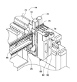
- FIG. 1 shows the component mounting device 10.
- the component mounting device 10 is a device for executing component mounting work on the circuit base material 12.
- the component mounting device 10 includes a device main body 20, a base material transfer holding device 22, a component mounting device 24, an image pickup device 26, 28, a loose component supply device 30, a component supply device 32, and a control device (see FIG. 5) 36.
- the circuit board 12 include a circuit board, a base material having a three-dimensional structure, and the like, and examples of the circuit board include a printed wiring board and a printed circuit board.
- the device main body 20 is composed of a frame 40 and a beam 42 mounted on the frame 40.
- the base material transfer holding device 22 is arranged at the center of the frame 40 in the front-rear direction, and has a transfer device 50 and a clamp device 52.
- the transport device 50 is a device that transports the circuit base material 12
- the clamp device 52 is a device that holds the circuit base material 12.
- the base material transport / holding device 22 transports the circuit base material 12 and holds the circuit base material 12 fixedly at a predetermined position.
- the transport direction of the circuit base material 12 is referred to as the X direction
- the horizontal direction perpendicular to that direction is referred to as the Y direction
- the vertical direction is referred to as the Z direction. That is, the width direction of the component mounting device 10 is the X direction, and the front-rear direction is the Y direction.
- the component mounting device 24 is arranged on the beam 42, and has two work heads 60 and 62 and a work head moving device 64. As shown in FIG. 2, a chuck 66 is detachably provided on the lower end surfaces of the work heads 60 and 62, and the chuck 66 holds a component. Further, the work head moving device 64 includes an X-direction moving device 68, a Y-direction moving device 70, and a Z-direction moving device 72. Then, the two work heads 60 and 62 are integrally moved to an arbitrary position on the frame 40 by the X-direction moving device 68 and the Y-direction moving device 70.
- the work heads 60 and 62 are mounted on the sliders 74 and 76 so as to be detachably and detachably positioned with one touch without using a tool, and the Z-direction moving device 72 individually moves the sliders 74 and 76 in the vertical direction. Move. That is, the work heads 60 and 62 are individually moved in the vertical direction by the Z-direction moving device 72.
- the image pickup device 26 is attached to the slider 74 in a state of facing downward on the vertical axis, and is moved together with the work head 60 in the X direction, the Y direction, and the Z direction. As a result, the image pickup apparatus 26 images an arbitrary position on the frame 40. As shown in FIG. 1, the image pickup apparatus 28 is arranged between the substrate transport holding apparatus 22 on the frame 40 and the component supply apparatus 32 in a state of facing upward on the vertical axis. As a result, the image pickup apparatus 28 images the parts held by the chucks 66 of the work heads 60 and 62.
- the image pickup devices 26 and 28 are two-dimensional cameras, and capture a two-dimensional image.
- the loose parts supply device 30 is arranged at one end of the frame 40 in the front-rear direction.
- the loose parts supply device 30 is a device that aligns a plurality of parts that are scattered apart and supplies the parts in the aligned state. That is, it is a device that aligns a plurality of parts in an arbitrary posture in a predetermined posture and supplies the parts in the predetermined posture.
- the parts supply device 32 is arranged at the other end of the frame 40 in the front-rear direction.
- the parts supply device 32 includes a tray-type parts supply device 78 and a feeder-type parts supply device 80.
- the tray-type component supply device 78 is a device that supplies components in a state of being placed on the tray.
- the feeder type component supply device 80 is a device for supplying components by a tape feeder 82, or a loose component feeder device for supplying a plurality of components in a scattered state.
- the structure of the tape feeder 82 will be described below, but the structure of the tape feeder 82 will be briefly described because it is described in detail in Japanese Patent Application No. 2019-150273, which the applicant has previously applied for.
- the tape feeder 82 is detachably positioned and mounted in the slot of the tape feeder holding base 86 fixedly provided at the other end of the frame 40 with a single touch.
- the tape feeder 82 is a taped lead component supply device in which the axial component is removed from the taped component (see FIG. 3) 88 and the lead wire of the removed axial component is bent and supplied to the work heads 60 and 62.
- the taped component 88 is a general taped component, and is referred to as a normal taped component 88 in order to distinguish it from the sequential taped component described in detail later.
- the normal taped component 88 is composed of a plurality of axial components 90 and two carrier tapes 92.
- the plurality of axial parts 90 are all parts of the same type, and each of all the axial parts 90 generally includes a columnar part body 96 and two lead wires 98.
- the two lead wires 98 are generally linear, and are fixed to both end faces of the component body 96 coaxially with the axis of the component body 96.
- the axial component 90 is taped to the two carrier tapes 92 at the tips of the two lead wires 98, that is, the ends opposite to the component body 96, while being sandwiched between the two carrier tapes 92.
- the plurality of axial parts 90 are taped on two carrier tapes 92 at equal pitches.
- the tape feeder 82 includes a storage box 100 and a feeder main body 102.
- the direction from the storage box 100 toward the feeder main body 102 is described as the front, and the direction from the feeder main body 102 toward the storage box 100 is described as the rear.
- the taped parts 88 are stored in the storage box 100 in a folded state. Then, the normal taped part 88 stored in the storage box 100 is pulled out, and the normal taped part 88 extends to the upper end surface of the feeder main body 102.
- the feeder main body 102 is provided with a feeding device 110, a lead cutting device 112, a bending device 114, and a detection sensor 116.
- the feeding device 110 feeds the normal taped component 88 extending to the upper surface of the feeder main body 102 toward the front. At this time, the feeding device 110 feeds the normal taped component 88 at the same pitch as the arrangement pitch of the axial parts 90 taped to the normal taped component 88.
- a lead cutting device 112 is arranged on the front side of the feeding device 110, and the lead cutting device 112 is a pair of the normal taped parts 88 each time the normal taped component 88 is sent out by the feeding device 110. Lead wire 98 is cut at a predetermined position. As a result, one axial component 90 is separated from the normal taped component 88.
- the bending device 114 clamps the pair of lead wires 98 of the axial component 90 separated from the normal taped component 88, and the bending device 114 rises in a state where the pair of lead wires 98 of the axial component 90 are clamped. ..
- the pair of lead wires 98 abuts on the pair of bending rollers (not shown) arranged above, so that the tip portion outside the clamped portion of the pair of lead wires 98 moves downward. Bend to face.
- the axial component 90 in a state where the pair of lead wires 98 are bent is supplied.
- the position where the bending device 114 is raised is the component supply position of the tape feeder 82, and the axial component 90 is supplied at that position.
- a detection sensor 116 is arranged at the supply position of the tape feeder 82, and the presence / absence of the axial component 90 at the supply position is detected by the detection sensor 116.
- the control device 36 includes a controller 120, a plurality of drive circuits 122, and an image processing device 126.
- the plurality of drive circuits 122 include the transfer device 50, the clamp device 52, the work heads 60 and 62, the X direction moving device 68, the Y direction moving device 70, the Z direction moving device 72, the tray type component supply device 78, and the tape feeder 82. , It is connected to the loose parts supply device 30.
- the controller 120 includes a CPU, ROM, RAM, etc., and is mainly a computer, and is connected to a plurality of drive circuits 122. As a result, the operation of the base material transfer holding device 22, the component mounting device 24, and the like is controlled by the controller 120.
- the controller 120 is also connected to the image processing device 126.
- the image processing device 126 processes the image data obtained by the image pickup devices 26 and 28, and the controller 120 acquires various information from the image data.
- the controller 120 is also connected to the detection sensor 116 of the tape feeder 82. As a result, the controller 120 acquires the value detected by the detection sensor 116.
- the component mounting work is performed on the circuit base material 12 held by the base material transport holding device 22 according to the above-described configuration.
- the transport device 50 transports the circuit base material 12 to the working position according to the command of the controller 120, and the clamp device 52 fixedly holds the circuit base material 12 at that position.
- the image pickup apparatus 26 moves above the circuit base material 12 according to the command of the controller 120, and images the circuit base material 12.
- the controller 120 acquires information regarding the positions of a pair of through holes (not shown) formed in the circuit base material 12.
- the loose parts supply device 30 or the parts supply device 32 supplies parts to the work heads 60 and 62 at predetermined supply positions.
- the supply of the axial component 90 by the tape feeder 82 of the component supply device 32 will be described.
- the controller 120 outputs a first feed instruction to the tape feeder 82 when the component to be mounted is a component normally supplied from the taped component 88. Then, when the tape feeder 82 receives the first feed instruction, it operates the feed device 110, the lead cutting device 112, and the bending device 114 to supply the axial component 90. Then, when the tape feeder 82 supplies the axial component 90, the detection sensor 116 detects whether or not the component is present at the supply position. At this time, normally, the detection sensor 116 detects that there is a component at the supply position, and the tape feeder 82 provides information indicating that the component is at the supply position (hereinafter, referred to as “part presence information”) in the controller 120. Output to.
- component mounting start instruction an instruction to start the component mounting work (hereinafter, referred to as "component mounting start instruction") to the work heads 60 and 62.
- component mounting start instruction an instruction to start the component mounting work
- the controller 120 acquires information regarding the tip positions of the pair of lead wires 98 of the axial component 90 held by the chuck 66.
- the work heads 60 and 62 move above the circuit base material 12 so that the pair of through holes of the circuit base material 12 and the pair of lead wires 98 of the axial component 90 match in XY coordinates. ..
- the pair of lead wires 98 of the axial component 90 are inserted into the pair of through holes of the circuit base material 12.
- the axial component 90 is mounted on the circuit base material 12.
- the tape feeder 82 that receives the first feed instruction from the controller 120 performs the supply work of the axial component 90, which is a normal taped component, by the operation of the feeder 110 and the like, and at the supply position by the detection sensor 116.
- the detection sensor 116 may not detect the component.
- the reasons for this are the taping error of the part in the normal taped part 88, the misalignment of the part due to the defect of cutting the lead wire 98 by the lead cutting device 112, and the lead wire of the axial part separated from the carrier tape by the bending device 114.
- the clamp position may be misaligned due to the clamp device of the above, or the clamp may be defective.
- the tape feeder 82 again does not receive an instruction from the controller 120 and is a feeding device.
- the 110 and the like are operated to supply the axial component 90.
- the tape feeder 82 again detects the presence or absence of the component at the supply position by the detection sensor 116.
- the detection sensor 116 detects that there is a component at the supply position
- the tape feeder 82 outputs the component presence information to the controller 120, so that the mounting operation of the axial component 90 is executed as described above. ..
- the tape feeder 82 executes the supply operation of the axial component 90, and when the axial component 90 is not supplied at the supply position, the axial component 90 is supplied at the supply position.
- the supply operation of the axial component 90 is repeatedly executed until the auxiliary component 90 is supplied. This makes it possible to appropriately supply the axial component 90, which is a normal tape component, at the supply position of the tape feeder 82.
- the tape feeder 82 can supply not only the axial component 90 from the normal taped component 88 but also the axial component from the sequential taped component.
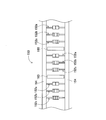
- the sequential taped component 150 is also composed of a plurality of axial components 152 and two carrier tapes 154 as shown in FIG.
- a plurality of axial components for each panel or each board are collectively taped. That is, for example, when three types of axial parts 152a, b, c are to be mounted on one panel or board, the three types of axial parts 152a, b, c have the feed pitch of the taped parts. It is continuously taped on the carrier tape 154.
- these three types of axial parts 152a, b, and c are repeatedly taped on the carrier tape 154. That is, the three types of axial parts 152a, b, and c that are continuously taped to the carrier tape 154 are a plurality of axial parts (hereinafter, referred to as "parts group”) in a panel unit or a board unit.
- the component group is repeatedly taped to the carrier tape 154.
- the space between the parts group and the parts group is 160, which is a space where parts are not taped (hereinafter, referred to as "empty taping space").
- the three types of axial parts 152a, b, and c constituting the parts group are taped to the carrier tape 154 for each pitch which is the feed pitch of the taped parts, and the parts are one pitch behind the parts group. Is not taped, and one pitch behind the component group is an empty taping space 160. Then, from two pitches behind the component group, three types of axial components 152a, b, and c constituting a component group different from the component group are taped to the carrier tape 154 for each pitch.
- the empty taping space 160 between the parts group and the parts group in this way, it is possible to confirm that the work of mounting the parts on one panel or one board is completed. That is, it can be confirmed that the mounting work of one component group has been completed.
- the sequential taped component 150 is placed on the tape feeder 82 so that the empty taping space 160 is located at the supply position of the tape feeder 82.
- the controller 120 confirms whether or not there is a component at the supply position of the tape feeder 82 before the circuit base material 12 is carried into the component mounting device 10 and the mounting work on the circuit base material 12 is started.
- An instruction to the effect (hereinafter referred to as "part presence / absence confirmation instruction") is output to the tape feeder 82.
- the controller 120 completes the mounting work on one board not only when the circuit base material 12 is carried into the component mounting device 10 but also when the circuit base material 12 is composed of a plurality of boards. However, even before starting the mounting work on another board, the component presence / absence confirmation instruction is output to the tape feeder 82. That is, when the component to be mounted is a component supplied from the sequential taped component 150, the controller 120 is required to perform the mounting work on one panel or one board before newly starting the mounting work. A component presence / absence confirmation instruction is output to the tape feeder 82.
- the detection sensor 116 detects the presence / absence of the component at the supply position.
- the detection sensor 116 detects that there is no component at the supply position, and the tape feeder 82 indicates that the component is not at the supply position (information indicating that the component is not at the supply position ( Hereinafter, "partless information") is output to the controller 120.
- the controller 120 receives the component-less information, it outputs a second feed instruction to the tape feeder 82.
- the tape feeder 82 When the tape feeder 82 receives the second feed instruction, it operates the feed device 110, the lead cutting device 112, and the bending device 114 to supply the axial component 152 to the supply position. Then, when the tape feeder 82 supplies the axial component 152, the detection sensor 116 detects whether or not the component is present at the supply position. At this time, normally, the detection sensor 116 detects that there is a component at the supply position, and the tape feeder 82 outputs information indicating that the component is at the supply position, that is, component presence information to the controller 120. Then, when the controller 120 receives the component presence information, it outputs an instruction to start the component mounting work to the work heads 60 and 62, that is, a component mounting start instruction.
- the work heads 60 and 62 move above the supply position of the tape feeder 82, and the chuck 66 holds the axial component 152 supplied to the supply position. Then, as described above, the imaging device 28 takes an image of the axial component 152, and the mounting work of the axial component 152 on the circuit base material 12 is executed.
- the tape feeder 82 that receives the second feed instruction from the controller 120 performs the supply work of the axial component 152 by the operation of the feeder 110 and the like, and detects the presence or absence of the component at the supply position by the detection sensor 116. In some cases, the detection sensor 116 may not detect the component.
- the reasons for this are the same as the reasons described above, the taping error of the component in the sequential taped component 150, the misalignment of the component due to the defect of cutting the lead wire 98 by the lead cutting device 112, and the carrier tape by the bending device 114.
- the clamp position of the lead wire of the axial component separated from the cable is misaligned, or the clamp is defective.
- the tape feeder 82 executes the component supply operation again.
- the tape feeder 82 does not re-execute the component supply operation. This is because, in the sequential taped component 150, when the component supply operation is executed but there is no component at the supply position, when the component supply operation is executed again, the component is at the planned mounting position. This is because it may be mounted in a different position.
- the axial component 152a is planned to be supplied at the supply position in the component mounting program. Instead, when the detection sensor 116 determines that the component is not in the supply position, the tape feeder 82 supplies the component again, and the axial component 152b is supplied to the supply position. On the other hand, since the axial component 152a has not been supplied and the work of mounting the axial component 152a on the circuit base material 12 has not been executed, the component is naturally mounted at the planned mounting position of the axial component 152a. Not.
- the tape feeder 82 supplies the components from the sequential tape component 150, the tape is not detected by the detection sensor 116 even though the component supply operation is executed.
- the feeder 82 does not re-execute the component supply operation. Instead, the tape feeder 82 outputs information indicating that the component is not in the supply position, that is, component-less information to the controller 120.
- the controller 120 receives the component-less information, it executes an error notification and gives an instruction to the work heads 60, 62, the tape feeder 82, etc. to stop the component mounting work (hereinafter, "component mounting stop instruction"). To be described) is output.
- Examples of the error notification include error display on the display device (not shown) of the component mounting device 10, output of a warning sound by the speaker (not shown), lighting and blinking of lamps and lights for notification, and the like. Be done. As a result, the component mounting work is temporarily stopped, and the operator recognizes the error, so that the circuit base material 12 can be paid out, the mounting work of the axial component 152a that was not supplied can be skipped, and the like.
- the controller 120 when the component is normally supplied from the taped component 88 in the component mounting program, the controller 120 outputs the first feed instruction to the tape feeder 82.
- the tape feeder 82 executes the component supply operation, but if the component is not detected by the detection sensor 116 at the supply position after executing the supply operation, the tape feeder 82 resupplys the component. Run.
- the axial component 90 is supplied from the normal taped component 88 on which the same type of component is taped, and the appropriate mounting work of the axial component 90 is guaranteed.
- the controller 120 when the component is supplied from the sequential tape component 150 in the component mounting program, the controller 120 outputs the second feed instruction to the tape feeder 82.
- the tape feeder 82 receives the second feed instruction, the component supply operation is executed, but the component is not detected by the detection sensor 116 at the supply position even though the supply operation is executed in the component mounting program. Even in this case, the parts are not resupplied. Instead, the tape feeder 82 outputs component-less information to the controller 120. As a result, the controller 120 executes the error notification and outputs the component mounting stop instruction, so that it is possible to prevent erroneous mounting at a position different from the planned mounting position of the component.
- the tape feeder 82 in the component mounting program detects the presence / absence of the component by the detection sensor 116 according to the component presence / absence confirmation instruction, and in the component mounting program, the component is detected even though the taping space is empty, and the component is mounted.
- the tape feeder 82 detects the presence / absence of the component by the detection sensor 116 according to the component presence / absence confirmation instruction in the component mounting program, and when the component is detected, the information indicating that the component is in the supply position, that is, the component.
- the presence information is output to the controller 120.
- the controller 120 receives the component presence information, the component is detected in the component mounting program even though it is an empty taping space, so that an error notification is executed, and the work heads 60 and 62 and the tape feeder 82 are executed.
- the operator sets an appropriate sequential taped component 150 in the tape feeder 82 so that the empty taping space 160 is located at the supply position of the tape feeder 82, so that the control device can control the component at the component supply position.
- the position of the head of the part group on the sequential tape can be grasped, so that it corresponds to one panel or one board.
- the component group can be mounted in the appropriate position.
- the tape feeder 82 detects the presence / absence of parts by the detection sensor 116 according to the component presence / absence confirmation instruction, so that the parts can be appropriately supplied from the sequential taped parts 150 for each panel or board. Has been done.
- the conventional tape feeder is not provided with a detection sensor for detecting the presence or absence of a component at the supply position, the sequential tape component 150 can be used without using the detection signal from the detection sensor of the tape feeder. The supply of appropriate parts was guaranteed for each panel or board.
- the work heads 60 and 62 hold the parts from the supply position in order to confirm that the empty taping space 160 is located at the supply position of the tape feeder 82 before the new mounting work is executed. Do the work.
- the work heads 60 and 62 cannot hold the component.
- the work heads 60 and 62 perform the blank driving operation of the parts in order to confirm that the parts are not held.
- the blank driving work is to execute the work of mounting the parts on the circuit base material 12 even though the work heads 60 and 62 do not hold the parts.
- a through hole for inserting the lead wire is formed in the circuit base material 12, and the presence or absence of the lead wire inserted into the through hole is detected by a detection sensor or the like.
- the detection sensor or the like does not detect that the lead wire has been inserted into the through hole, so that the parts are not held by the work heads 60 and 62. Is confirmed. From this detection result, it is confirmed that the empty taping space 160 is located at the supply position of the tape feeder 82, and the mounting work of the component group is started.
- the work heads 60 and 62 perform the blank driving work of the parts, the insertion of the lead wire into the through hole of the circuit equipment may be detected.
- the work heads 60 and 62 hold the parts, and the parts are mounted in the through holes of the circuit equipment. That is, it is confirmed that the parts are supplied to the supply position of the tape feeder 82 and the empty taping space 160 is not located. Therefore, in such a case, an error notification is made from the control device, and an instruction to stop the component mounting work to the work heads 60, 62, the tape feeder 82, etc., that is, a component mounting stop instruction is output. ..
- the tape feeder 82 is provided with a detection sensor 116 that detects the presence / absence of a component at the supply position, and the tape feeder 82 detects the presence / absence of a component by the detection sensor 116 in accordance with a component presence / absence confirmation instruction from the controller 120. You can check. As a result, it is possible to eliminate waste such as holding operation of empty parts of the work head and blank striking operation on the circuit base material 12, and supplying parts from the sequential taped part 150 in units of panels or boards. It can be executed efficiently and accurately.
- the mounting work of the axial component 90 supplied from the normal taped component 88 and the mounting work of the axial component 152 supplied from the sequential taped component 150 described above are the main program (see FIG. 5) 170 and the feeder program. (See FIG. 5) It is executed by the process of 172.
- the processing by the main program 170 will be described with reference to the flowcharts of FIGS. 7 and 8, and the processing by the feeder program 172 will be described with reference to the flowchart of FIG.
- the main program 170 is executed by the controller 120, and as shown in FIG. 7, the controller 120 determines whether or not the component to be mounted is a component supplied from the sequential taped component 150.
- S100 Specifically, a job for executing the work of mounting parts on the circuit base material is created for each type of circuit base material, and when creating a job according to the type of circuit base material, the parts to be mounted are created. , It is set whether it is a component normally supplied from the taped component 88, a component supplied from the sequential taped component 150, or a component supplied from another type of component supply device. ing.
- the component to be mounted is a component normally supplied from the taped component 88, a component supplied from the sequential taped component 150, or a tape. It is possible to identify whether the component is supplied from a component supply device of a type other than the feeder. That is, on the main program 170, it is possible to identify whether the component supplied from the tape feeder 82 is a component supplied from the normal taped component 88 or a component supplied from the sequential taped component 150. It is possible.
- the controller 120 determines whether or not there is a component at the supply position (S104). That is, the controller 120 determines whether or not the component presence information has been received from the tape feeder 82 in response to the output of the first feed instruction.
- the process of S104 is performed. repeat. That is, since the tape feeder 82 that has received the first feed instruction outputs the first feed instruction and repeatedly executes the component supply operation until the component is detected by the detection sensor 116, the controller 120 causes the tape feeder 82. The process of S104 is repeated until the information on the presence of parts is received. Then, when the controller 120 receives the component presence information from the tape feeder 82, that is, when the component is present at the supply position (S104: YES), the controller 120 outputs the component mounting start instruction to the work heads 60 and 62 (S106). .. As a result, the mounting work of the axial component 90 normally supplied from the taped component 88 is executed.
- the controller 120 determines whether or not it is a new mounting operation. (S108). At this time, when it is a new mounting work (S108: YES), that is, at the start of the mounting work on a new panel or a new board in the circuit equipment, or the mounting work of a new component group. At the start of the above, the controller 120 outputs a component presence / absence confirmation instruction to the tape feeder 82 (S110). Next, the controller 120 determines whether or not there is a component at the supply position (S112).
- the controller 120 determines whether the tape feeder 82 has received the component presence information or the component absence information in response to the output of the component presence / absence confirmation instruction. At this time, when the controller 120 receives the component-less information from the tape feeder 82, that is, when there is no component at the supply position (S112: NO), it is determined that the controller 120 is an empty taping space in the sequential taped component, and FIG. The second feed instruction is output to the tape feeder 82 as shown in (S118).
- the controller 120 determines whether or not there is a component at the supply position (S120). That is, the controller 120 determines whether the information with parts or the information without parts is received from the tape feeder 82 in response to the output of the second feed instruction. At this time, when the controller 120 receives the component presence information from the tape feeder 82, that is, when the component is present at the supply position (S120: YES), the first component of the component group in the sequential tape component supplies the tape feeder. It is determined that the controller 120 has been supplied to the position, and the controller 120 outputs a component mounting start instruction to the work heads 60 and 62 (S122). As a result, the mounting work of the axial component 90, which is a component group supplied from the sequential tape component 150, is executed.
- the controller 120 executes an error notification (S124) and stops mounting the component.
- the instruction is output to a notification device such as the work heads 60 and 62, the tape feeder 82, the operation panel, and the signal tower (S126).
- a notification device such as the work heads 60 and 62, the tape feeder 82, the operation panel, and the signal tower (S126).
- the controller 120 determines whether or not there is a component at the supply position (S120). That is, the controller 120 determines which type of information, the information with parts or the information without parts, is received from the tape feeder 82 in response to the output of the second feed instruction. At this time, when the controller 120 receives the component presence information from the tape feeder 82, that is, when it is confirmed that the component is present at the supply position (S120: YES), the controller 120 issues a component mounting start instruction to the work head.
- the feeder program 172 is executed by the tape feeder 82, and the tape feeder 82 determines whether or not the first feed instruction has been received from the controller 120 as shown in FIG. 9 (S200). At this time, when the first feed instruction is received (S200: YES), the tape feeder 82 executes the supply operation of supplying the taped parts to the supply position (S202). Then, the tape feeder 82 detects the presence / absence of a component at the supply position by the detection sensor 116 (S204). At this time, if the detection sensor 116 detects that there is no component (S204: NO), the processes of S202 and S204 are executed again.
- the tape feeder 82 executes the operation of supplying the taped parts to the supply position (S202), and detects the presence or absence of the parts at the supply position by the detection sensor 116 (S204). Then, when the detection sensor 116 detects that there is a component at the supply position (S204: YES), the tape feeder 82 outputs the component presence information to the controller 120 (S206). That is, when the tape feeder 82 receives the first feed instruction, the tape feeder 82 repeats the component supply operation and the detection of the presence / absence of the component at the supply position until the detection sensor 116 detects the component at the supply position.
- the tape feeder 82 determines whether or not the second feed instruction is received from the controller 120 (S208). At this time, when the second feed instruction is accepted (S208: YES), the tape feeder 82 executes the operation of supplying the taped parts to the supply position (S210). Then, the tape feeder 82 detects the presence / absence of a component at the supply position by the detection sensor 116 (S212). At this time, when the detection sensor 116 detects that there is a component at the supply position (S212: YES), the tape feeder 82 outputs a signal with the component to the controller 120 (S206). On the other hand, when the detection sensor 116 detects that there is no component at the supply position (S212: NO), the tape feeder 82 outputs a signal without the component to the controller 120 (S214).
- the tape feeder 82 determines whether or not the component presence / absence confirmation instruction has been received from the controller 120 (S216). At this time, when the component presence / absence confirmation instruction is received (S216: YES), the tape feeder 82 detects the presence / absence of the component at the supply position by the detection sensor 116 (S212). At this time, when the detection sensor 116 detects that there is a component at the supply position (S212: YES), the tape feeder 82 outputs a signal with the component to the controller 120 (S206). On the other hand, when the detection sensor 116 detects that there is no component (S212: NO), the tape feeder 82 outputs a signal without the component to the controller 120 (S214).
- the tape feeder 82 is an example of a tape feeder.
- the normal taped component 88 is an example of a taped component other than the sequential taped component.
- the sequential taped component 150 is an example of a sequential taped component.
- the main program 170 is an example of a component mounting program.
- S110 is an example of a confirmation instruction output means.
- S116 is an example of the second stopping means.
- S118 is an example of a feed instruction output means.
- S126 is an example of the first stopping means.
- the present invention is not limited to the above-mentioned examples, and can be carried out in various modes with various changes and improvements based on the knowledge of those skilled in the art.
- the controller 120 which type of taped component, the sequential taped component 150 or the normal taped component 88, is the component to be mounted. Judgment is based on the job being done.
- the parts to be mounted are not limited to the jobs input to the controller 120, and can be obtained from any type of taped parts, the sequential taped parts 150 and the normal taped parts 88, by various methods. It may be determined whether the parts are supplied.
- the operator may input the type of the component to be mounted, and the target component of the mounting work may be determined based on the input value.
- the imaging device 26 may image the tape feeder 82, and the target component of the mounting work may be determined based on the imaging data. Further, even when the operator visually recognizes the component mounting program, it is possible to determine which type of taped component is supplied from each of the taped components mounted in the component mounting program. ..
- the presence / absence of parts is detected by the detection sensor 116 at the supply position, but the presence / absence of parts may be detected by another device.
- the supply position of the tape feeder 82 may be imaged by an imaging device 26 that moves together with the work head, and the presence or absence of a component at the supply position of each tape feeder may be detected based on the imaged data.
- the present invention is applied to a tape feeder that supplies axial parts, it may be applied to a tape feeder that supplies radial parts or a tape feeder of a general square tip. That is, regardless of the type of taped parts, when the radial parts and square chips taped on the carrier tape are supplied, the first feed instruction, the second feed instruction, the component presence / absence confirmation instruction, etc. are taped from the controller 120. It may be output to the feeder and the tape feeder may operate according to the instructions.
Landscapes
- Engineering & Computer Science (AREA)
- Manufacturing & Machinery (AREA)
- Microelectronics & Electronic Packaging (AREA)
- Operations Research (AREA)
- Supply And Installment Of Electrical Components (AREA)
Abstract
In this component mounting program for mounting a component on a substrate, it is possible to identify whether a component fed from a tape feeder on the component mounting program is a component fed from a sequential taped component or a component fed from a taped component other than the sequential taped component.
Description
本発明は、基板に部品を実装するための部品実装プログラムに関する。
The present invention relates to a component mounting program for mounting components on a board.
下記特許文献には、部品がテーピングされたテープ化部品がテープフィーダにセットされており、そのテープ化部品から供給された部品が、基板に装着される技術が記載されている。
The following patent document describes a technique in which a taped component with taped components is set in a tape feeder, and the component supplied from the taped component is mounted on a substrate.
本発明は、テープ化部品から適切に部品を供給することを課題とする。
An object of the present invention is to appropriately supply parts from taped parts.
上記課題を解決するために、本明細書は、基板に部品を実装するための部品実装プログラムにおいて、前記部品実装プログラム上のテープフィーダから供給される部品が、シーケンシャルテープ化部品から供給される部品か、シーケンシャルテープ化部品以外のテープ化部品から供給される部品かを識別可能な部品実装プログラムを開示する。
In order to solve the above problems, in the present specification, in a component mounting program for mounting a component on a board, a component supplied from a tape feeder on the component mounting program is a component supplied from a sequential taped component. Disclose a component mounting program that can identify whether the component is supplied from a taped component other than the sequential taped component.
本開示によれば、実装プログラムにおいて、実装対象の部品が、シーケンシャルテープ化部品から供給される部品か、シーケンシャルテープ化部品以外のテープ化部品から供給される部品かを識別することが可能とされている。これにより、テープ化部品の種類に応じて適切に部品を供給することができる。
According to the present disclosure, in a mounting program, it is possible to identify whether a component to be mounted is a component supplied from a sequential taped component or a component supplied from a taped component other than the sequential taped component. ing. Thereby, the parts can be appropriately supplied according to the type of the taped parts.
以下、本発明を実施するための形態として、本発明の実施例を、図を参照しつつ詳しく説明する。
Hereinafter, examples of the present invention will be described in detail with reference to the drawings as a mode for carrying out the present invention.
図1に、部品実装装置10を示す。部品実装装置10は、回路基材12に対する部品の実装作業を実行するための装置である。部品実装装置10は、装置本体20、基材搬送保持装置22、部品装着装置24、撮像装置26,28、ばら部品供給装置30、部品供給装置32、制御装置(図5参照)36を備えている。なお、回路基材12として、回路基板、三次元構造の基材等が挙げられ、回路基板として、プリント配線板、プリント回路板等が挙げられる。
FIG. 1 shows the component mounting device 10. The component mounting device 10 is a device for executing component mounting work on the circuit base material 12. The component mounting device 10 includes a device main body 20, a base material transfer holding device 22, a component mounting device 24, an image pickup device 26, 28, a loose component supply device 30, a component supply device 32, and a control device (see FIG. 5) 36. There is. Examples of the circuit board 12 include a circuit board, a base material having a three-dimensional structure, and the like, and examples of the circuit board include a printed wiring board and a printed circuit board.
装置本体20は、フレーム40と、そのフレーム40に上架されたビーム42とによって構成されている。基材搬送保持装置22は、フレーム40の前後方向の中央に配設されており、搬送装置50とクランプ装置52とを有している。搬送装置50は、回路基材12を搬送する装置であり、クランプ装置52は、回路基材12を保持する装置である。これにより、基材搬送保持装置22は、回路基材12を搬送するとともに、所定に位置において、回路基材12を固定的に保持する。なお、以下の説明において、回路基材12の搬送方向をX方向と称し、その方向に直角な水平の方向をY方向と称し、鉛直方向をZ方向と称する。つまり、部品実装装置10の幅方向は、X方向であり、前後方向は、Y方向である。
The device main body 20 is composed of a frame 40 and a beam 42 mounted on the frame 40. The base material transfer holding device 22 is arranged at the center of the frame 40 in the front-rear direction, and has a transfer device 50 and a clamp device 52. The transport device 50 is a device that transports the circuit base material 12, and the clamp device 52 is a device that holds the circuit base material 12. As a result, the base material transport / holding device 22 transports the circuit base material 12 and holds the circuit base material 12 fixedly at a predetermined position. In the following description, the transport direction of the circuit base material 12 is referred to as the X direction, the horizontal direction perpendicular to that direction is referred to as the Y direction, and the vertical direction is referred to as the Z direction. That is, the width direction of the component mounting device 10 is the X direction, and the front-rear direction is the Y direction.
部品装着装置24は、ビーム42に配設されており、2台の作業ヘッド60,62と作業ヘッド移動装置64とを有している。各作業ヘッド60,62の下端面には、図2に示すように、チャック66が着脱可能に設けられており、チャック66によって部品を保持する。また、作業ヘッド移動装置64は、X方向移動装置68とY方向移動装置70とZ方向移動装置72とを有している。そして、X方向移動装置68とY方向移動装置70とによって、2台の作業ヘッド60,62は、一体的にフレーム40上の任意の位置に移動させられる。また、各作業ヘッド60,62は、スライダ74,76に工具を用いることなくワンタッチで着脱可能に位置決めして装着されており、Z方向移動装置72は、スライダ74,76を個別に上下方向に移動させる。つまり、作業ヘッド60,62は、Z方向移動装置72によって、個別に上下方向に移動させられる。
The component mounting device 24 is arranged on the beam 42, and has two work heads 60 and 62 and a work head moving device 64. As shown in FIG. 2, a chuck 66 is detachably provided on the lower end surfaces of the work heads 60 and 62, and the chuck 66 holds a component. Further, the work head moving device 64 includes an X-direction moving device 68, a Y-direction moving device 70, and a Z-direction moving device 72. Then, the two work heads 60 and 62 are integrally moved to an arbitrary position on the frame 40 by the X-direction moving device 68 and the Y-direction moving device 70. Further, the work heads 60 and 62 are mounted on the sliders 74 and 76 so as to be detachably and detachably positioned with one touch without using a tool, and the Z-direction moving device 72 individually moves the sliders 74 and 76 in the vertical direction. Move. That is, the work heads 60 and 62 are individually moved in the vertical direction by the Z-direction moving device 72.
撮像装置26は、鉛直軸線上において下方を向いた状態でスライダ74に取り付けられており、作業ヘッド60とともに、X方向,Y方向およびZ方向に移動させられる。これにより、撮像装置26は、フレーム40上の任意の位置を撮像する。撮像装置28は、図1に示すように、フレーム40上の基材搬送保持装置22と部品供給装置32との間に、鉛直軸線上において上方を向いた状態で配設されている。これにより、撮像装置28は、作業ヘッド60,62のチャック66に保持された部品を撮像する。なお、撮像装置26,28は、2次元カメラとされており、2次元画像を撮像する。
The image pickup device 26 is attached to the slider 74 in a state of facing downward on the vertical axis, and is moved together with the work head 60 in the X direction, the Y direction, and the Z direction. As a result, the image pickup apparatus 26 images an arbitrary position on the frame 40. As shown in FIG. 1, the image pickup apparatus 28 is arranged between the substrate transport holding apparatus 22 on the frame 40 and the component supply apparatus 32 in a state of facing upward on the vertical axis. As a result, the image pickup apparatus 28 images the parts held by the chucks 66 of the work heads 60 and 62. The image pickup devices 26 and 28 are two-dimensional cameras, and capture a two-dimensional image.
ばら部品供給装置30は、フレーム40の前後方向での一方側の端部に配設されている。ばら部品供給装置30は、ばらばらに散在された状態の複数の部品を整列させて、整列させた状態で部品を供給する装置である。つまり、任意の姿勢の複数の部品を、所定の姿勢に整列させて、所定の姿勢の部品を供給する装置である。
The loose parts supply device 30 is arranged at one end of the frame 40 in the front-rear direction. The loose parts supply device 30 is a device that aligns a plurality of parts that are scattered apart and supplies the parts in the aligned state. That is, it is a device that aligns a plurality of parts in an arbitrary posture in a predetermined posture and supplies the parts in the predetermined posture.
部品供給装置32は、フレーム40の前後方向での他方側の端部に配設されている。部品供給装置32は、トレイ型部品供給装置78とフィーダ型部品供給装置80とを有している。トレイ型部品供給装置78は、トレイ上に載置された状態の部品を供給する装置である。フィーダ型部品供給装置80は、テープフィーダ82によって部品を供給する装置であったり、ばらばらに散在された状態の複数の部品を供給するばら部品フィーダ装置である。以下に、テープフィーダ82の構造について説明するが、テープフィーダ82の構造は、本出願人が先に出願している特願2019-150273号において詳しく説明しているため、簡略化して説明する。
The parts supply device 32 is arranged at the other end of the frame 40 in the front-rear direction. The parts supply device 32 includes a tray-type parts supply device 78 and a feeder-type parts supply device 80. The tray-type component supply device 78 is a device that supplies components in a state of being placed on the tray. The feeder type component supply device 80 is a device for supplying components by a tape feeder 82, or a loose component feeder device for supplying a plurality of components in a scattered state. The structure of the tape feeder 82 will be described below, but the structure of the tape feeder 82 will be briefly described because it is described in detail in Japanese Patent Application No. 2019-150273, which the applicant has previously applied for.
テープフィーダ82は、フレーム40の他方側の端部に固定的に設けられたテープフィーダ保持台86のスロットにワンタッチで着脱可能に位置決めして装着されている。テープフィーダ82は、テープ化部品(図3参照)88からアキシャル部品を取り外し、取り外したアキシャル部品のリード線を屈曲させた状態で作業ヘッド60,62に供給するテープ化リード部品供給装置である。なお、テープ化部品88は、一般的なテープ化部品であり、後に詳しく説明するシーケンシャルテープ化部品と区別するべく、通常テープ化部品88と記載する。
The tape feeder 82 is detachably positioned and mounted in the slot of the tape feeder holding base 86 fixedly provided at the other end of the frame 40 with a single touch. The tape feeder 82 is a taped lead component supply device in which the axial component is removed from the taped component (see FIG. 3) 88 and the lead wire of the removed axial component is bent and supplied to the work heads 60 and 62. The taped component 88 is a general taped component, and is referred to as a normal taped component 88 in order to distinguish it from the sequential taped component described in detail later.
通常テープ化部品88は、図3に示すように、複数のアキシャル部品90と2本のキャリアテープ92とから構成されている。複数のアキシャル部品90は、すべて同じ種類の部品であり、それら全てのアキシャル部品90の各々は、概して円柱状の部品本体96と、2本のリード線98とを含む。2本のリード線98は、概して直線状をなし、部品本体96の両端面に、部品本体96の軸心と同軸的に固定されている。そして、アキシャル部品90が、2本のキャリアテープ92に挟まれた状態で、2本のリード線98の先端、つまり、部品本体96と反対側の端において、2本のキャリアテープ92にテーピングされている。なお、複数のアキシャル部品90は、2本のキャリアテープ92に等ピッチでテーピングされている。
As shown in FIG. 3, the normal taped component 88 is composed of a plurality of axial components 90 and two carrier tapes 92. The plurality of axial parts 90 are all parts of the same type, and each of all the axial parts 90 generally includes a columnar part body 96 and two lead wires 98. The two lead wires 98 are generally linear, and are fixed to both end faces of the component body 96 coaxially with the axis of the component body 96. Then, the axial component 90 is taped to the two carrier tapes 92 at the tips of the two lead wires 98, that is, the ends opposite to the component body 96, while being sandwiched between the two carrier tapes 92. ing. The plurality of axial parts 90 are taped on two carrier tapes 92 at equal pitches.
また、テープフィーダ82は、図4に示すように、収納ボックス100と、フィーダ本体102とから構成されている。なお、以下の説明において、収納ボックス100からフィーダ本体102に向う方向を前方と記載し、フィーダ本体102から収納ボックス100に向う方向を後方と記載する。収納ボックス100には、通常テープ化部品88が折り畳まれた状態で収納されている。そして、収納ボックス100に収納されている通常テープ化部品88が引き出され、その通常テープ化部品88が、フィーダ本体102の上端面に延在されている。
Further, as shown in FIG. 4, the tape feeder 82 includes a storage box 100 and a feeder main body 102. In the following description, the direction from the storage box 100 toward the feeder main body 102 is described as the front, and the direction from the feeder main body 102 toward the storage box 100 is described as the rear. Normally, the taped parts 88 are stored in the storage box 100 in a folded state. Then, the normal taped part 88 stored in the storage box 100 is pulled out, and the normal taped part 88 extends to the upper end surface of the feeder main body 102.
そのフィーダ本体102には、送り装置110とリード切断装置112と屈曲装置114と検出センサ116とが配設されている。送り装置110は、フィーダ本体102の上面に延在されている通常テープ化部品88を前方に向って送り出す。この際、送り装置110は、通常テープ化部品88にテーピングされているアキシャル部品90の配設ピッチと同じピッチで、通常テープ化部品88を送り出す。その送り装置110の前方側には、リード切断装置112が配設されており、リード切断装置112は、送り装置110により通常テープ化部品88が送り出される毎に、通常テープ化部品88の1対のリード線98を、所定の位置において切断する。これにより、1個のアキシャル部品90が通常テープ化部品88から分離する。
The feeder main body 102 is provided with a feeding device 110, a lead cutting device 112, a bending device 114, and a detection sensor 116. The feeding device 110 feeds the normal taped component 88 extending to the upper surface of the feeder main body 102 toward the front. At this time, the feeding device 110 feeds the normal taped component 88 at the same pitch as the arrangement pitch of the axial parts 90 taped to the normal taped component 88. A lead cutting device 112 is arranged on the front side of the feeding device 110, and the lead cutting device 112 is a pair of the normal taped parts 88 each time the normal taped component 88 is sent out by the feeding device 110. Lead wire 98 is cut at a predetermined position. As a result, one axial component 90 is separated from the normal taped component 88.
そして、通常テープ化部品88から分離したアキシャル部品90の1対のリード線98を、屈曲装置114がクランプし、アキシャル部品90の1対のリード線98をクランプした状態で屈曲装置114が上昇する。この際、1対のリード線98が上方に配設された1対の屈曲ローラ(図示省略)に当接することで、1対のリード線98のクランプされた箇所より外側の先端部が下方を向くように屈曲する。そして、屈曲装置114が上昇した位置において、1対のリード線98が屈曲した状態のアキシャル部品90が供給される。つまり、屈曲装置114が上昇した位置が、テープフィーダ82の部品供給位置であり、その位置においてアキシャル部品90が供給される。なお、テープフィーダ82の供給位置には、検出センサ116が配設されており、供給位置におけるアキシャル部品90の有無が、検出センサ116により検出される。
Then, the bending device 114 clamps the pair of lead wires 98 of the axial component 90 separated from the normal taped component 88, and the bending device 114 rises in a state where the pair of lead wires 98 of the axial component 90 are clamped. .. At this time, the pair of lead wires 98 abuts on the pair of bending rollers (not shown) arranged above, so that the tip portion outside the clamped portion of the pair of lead wires 98 moves downward. Bend to face. Then, at the position where the bending device 114 is raised, the axial component 90 in a state where the pair of lead wires 98 are bent is supplied. That is, the position where the bending device 114 is raised is the component supply position of the tape feeder 82, and the axial component 90 is supplied at that position. A detection sensor 116 is arranged at the supply position of the tape feeder 82, and the presence / absence of the axial component 90 at the supply position is detected by the detection sensor 116.
また、制御装置36は、図5に示すように、コントローラ120、複数の駆動回路122、画像処理装置126を備えている。複数の駆動回路122は、上記搬送装置50、クランプ装置52、作業ヘッド60,62、X方向移動装置68、Y方向移動装置70、Z方向移動装置72、トレイ型部品供給装置78、テープフィーダ82、ばら部品供給装置30に接続されている。コントローラ120は、CPU,ROM,RAM等を備え、コンピュータを主体とするものであり、複数の駆動回路122に接続されている。これにより、基材搬送保持装置22、部品装着装置24等の作動が、コントローラ120によって制御される。また、コントローラ120は、画像処理装置126にも接続されている。画像処理装置126は、撮像装置26,28によって得られた画像データを処理するものであり、コントローラ120は、画像データから各種情報を取得する。さらに、コントローラ120は、テープフィーダ82の検出センサ116にも接続されている。これにより、コントローラ120は、検出センサ116による検出値を取得する。
Further, as shown in FIG. 5, the control device 36 includes a controller 120, a plurality of drive circuits 122, and an image processing device 126. The plurality of drive circuits 122 include the transfer device 50, the clamp device 52, the work heads 60 and 62, the X direction moving device 68, the Y direction moving device 70, the Z direction moving device 72, the tray type component supply device 78, and the tape feeder 82. , It is connected to the loose parts supply device 30. The controller 120 includes a CPU, ROM, RAM, etc., and is mainly a computer, and is connected to a plurality of drive circuits 122. As a result, the operation of the base material transfer holding device 22, the component mounting device 24, and the like is controlled by the controller 120. The controller 120 is also connected to the image processing device 126. The image processing device 126 processes the image data obtained by the image pickup devices 26 and 28, and the controller 120 acquires various information from the image data. Further, the controller 120 is also connected to the detection sensor 116 of the tape feeder 82. As a result, the controller 120 acquires the value detected by the detection sensor 116.
部品実装装置10では、上述した構成によって、基材搬送保持装置22に保持された回路基材12に対して部品の装着作業が行われる。具体的には、搬送装置50が、コントローラ120の指令に従って、回路基材12を作業位置まで搬送し、その位置において、クランプ装置52が回路基材12を固定的に保持する。次に、撮像装置26が、コントローラ120の指令に従って、回路基材12の上方に移動し、回路基材12を撮像する。これにより、コントローラ120は、回路基材12に形成された1対の貫通穴(図示省略)の位置に関する情報を取得する。また、ばら部品供給装置30若しくは、部品供給装置32は、所定の供給位置において、作業ヘッド60,62へ部品を供給する。なお、ここでは、部品供給装置32のテープフィーダ82によるアキシャル部品90の供給について説明する。
In the component mounting device 10, the component mounting work is performed on the circuit base material 12 held by the base material transport holding device 22 according to the above-described configuration. Specifically, the transport device 50 transports the circuit base material 12 to the working position according to the command of the controller 120, and the clamp device 52 fixedly holds the circuit base material 12 at that position. Next, the image pickup apparatus 26 moves above the circuit base material 12 according to the command of the controller 120, and images the circuit base material 12. As a result, the controller 120 acquires information regarding the positions of a pair of through holes (not shown) formed in the circuit base material 12. Further, the loose parts supply device 30 or the parts supply device 32 supplies parts to the work heads 60 and 62 at predetermined supply positions. Here, the supply of the axial component 90 by the tape feeder 82 of the component supply device 32 will be described.
コントローラ120は、装着対象の部品が、通常テープ化部品88から供給される部品である場合に、テープフィーダ82に第1送り指示を出力する。そして、テープフィーダ82は、第1送り指示を受け付けると、送り装置110,リード切断装置112,屈曲装置114を作動させ、アキシャル部品90の供給作業を行う。そして、テープフィーダ82は、アキシャル部品90の供給作業を行うときに、検出センサ116により供給位置に部品が有るか否かの検出を行う。この際、通常は、検出センサ116により供給位置に部品が有ると検出され、テープフィーダ82は、部品が供給位置にあることを示す情報(以下、「部品有り情報」と記載する)をコントローラ120に出力する。そして、コントローラ120は、部品有り情報を受け付けると、作業ヘッド60,62に部品の実装作業を開始する旨の指示(以下、「部品実装開始指示」と記載する)を出力する。これにより、作業ヘッド60,62は、テープフィーダ82の供給位置の上方に移動し、チャック66によって、供給位置のアキシャル部品90を保持する。
The controller 120 outputs a first feed instruction to the tape feeder 82 when the component to be mounted is a component normally supplied from the taped component 88. Then, when the tape feeder 82 receives the first feed instruction, it operates the feed device 110, the lead cutting device 112, and the bending device 114 to supply the axial component 90. Then, when the tape feeder 82 supplies the axial component 90, the detection sensor 116 detects whether or not the component is present at the supply position. At this time, normally, the detection sensor 116 detects that there is a component at the supply position, and the tape feeder 82 provides information indicating that the component is at the supply position (hereinafter, referred to as “part presence information”) in the controller 120. Output to. Then, when the controller 120 receives the component presence information, it outputs an instruction to start the component mounting work (hereinafter, referred to as "component mounting start instruction") to the work heads 60 and 62. As a result, the work heads 60 and 62 move above the supply position of the tape feeder 82, and the chuck 66 holds the axial component 90 at the supply position.
続いて、アキシャル部品90を保持した作業ヘッド60,62が、撮像装置28の上方に移動し、撮像装置28によって、チャック66に保持されたアキシャル部品90が撮像される。これにより、コントローラ120は、チャック66に保持されたアキシャル部品90の1対のリード線98の先端位置に関する情報を取得する。続いて、作業ヘッド60,62が、回路基材12の1対の貫通穴とアキシャル部品90の1対のリード線98とがXY座標において一致するように、回路基材12の上方に移動する。そして、作業ヘッド60,62が下降することで、回路基材12の1対の貫通穴に、アキシャル部品90の1対のリード線98が挿入される。これにより、アキシャル部品90が回路基材12に装着される。
Subsequently, the work heads 60 and 62 holding the axial parts 90 move above the image pickup device 28, and the image pickup device 28 images the axial parts 90 held by the chuck 66. As a result, the controller 120 acquires information regarding the tip positions of the pair of lead wires 98 of the axial component 90 held by the chuck 66. Subsequently, the work heads 60 and 62 move above the circuit base material 12 so that the pair of through holes of the circuit base material 12 and the pair of lead wires 98 of the axial component 90 match in XY coordinates. .. Then, as the work heads 60 and 62 are lowered, the pair of lead wires 98 of the axial component 90 are inserted into the pair of through holes of the circuit base material 12. As a result, the axial component 90 is mounted on the circuit base material 12.
一方で、コントローラ120から第1送り指示を受け付けたテープフィーダ82が、送り装置110等の作動により、通常のテープ化部品であるアキシャル部品90の供給作業を行って、検出センサ116により供給位置での部品の有無を検出する場合に、検出センサ116により部品が検出されない場合がある。この理由としては、通常テープ化部品88での部品のテーピングミス,リード切断装置112によるリード線98の切断の不具合による部品の位置ズレ,屈曲装置114によるキャリアテープから切り離されたアキシャル部品のリード線のクランプ装置によるクランプ位置のズレ、あるいはクランプの不具合等が挙げられる。このように、通常のテープ化部品150から部品が供給される際に、検出センサ116により部品が検出されない場合には、テープフィーダ82は、コントローラ120からの指示を受けることなく、再度、送り装置110等を作動させ、アキシャル部品90の供給作業を行う。そして、テープフィーダ82は、再度、検出センサ116による供給位置での部品の有無を検出する。この際、検出センサ116により供給位置に部品が有ると検出されると、テープフィーダ82は部品有り情報をコントローラ120に出力することで、上述したように、アキシャル部品90の装着作業が実行される。このように、テープフィーダ82は、コントローラ120から第1送り指示を受け付けると、アキシャル部品90の供給作業を実行し、アキシャル部品90が供給位置において供給されない場合に、アキシャル部品90が供給位置において供給されるまで、アキシャル部品90の供給作業を繰り返し実行する。これにより、テープフィーダ82の供給位置において適切に通常テープ化部品であるアキシャル部品90を供給することが可能となる。
On the other hand, the tape feeder 82 that receives the first feed instruction from the controller 120 performs the supply work of the axial component 90, which is a normal taped component, by the operation of the feeder 110 and the like, and at the supply position by the detection sensor 116. When detecting the presence or absence of a component, the detection sensor 116 may not detect the component. The reasons for this are the taping error of the part in the normal taped part 88, the misalignment of the part due to the defect of cutting the lead wire 98 by the lead cutting device 112, and the lead wire of the axial part separated from the carrier tape by the bending device 114. The clamp position may be misaligned due to the clamp device of the above, or the clamp may be defective. In this way, when the parts are supplied from the normal taped parts 150 and the parts are not detected by the detection sensor 116, the tape feeder 82 again does not receive an instruction from the controller 120 and is a feeding device. The 110 and the like are operated to supply the axial component 90. Then, the tape feeder 82 again detects the presence or absence of the component at the supply position by the detection sensor 116. At this time, when the detection sensor 116 detects that there is a component at the supply position, the tape feeder 82 outputs the component presence information to the controller 120, so that the mounting operation of the axial component 90 is executed as described above. .. As described above, when the tape feeder 82 receives the first feed instruction from the controller 120, the tape feeder 82 executes the supply operation of the axial component 90, and when the axial component 90 is not supplied at the supply position, the axial component 90 is supplied at the supply position. The supply operation of the axial component 90 is repeatedly executed until the auxiliary component 90 is supplied. This makes it possible to appropriately supply the axial component 90, which is a normal tape component, at the supply position of the tape feeder 82.
一方で、テープフィーダ82は、通常テープ化部品88からアキシャル部品90を供給するだけでなく、シーケンシャルテープ化部品からアキシャル部品を供給することも可能とされている。シーケンシャルテープ化部品150も、通常テープ化部品88と同様に、図6に示すように、複数のアキシャル部品152と2本のキャリアテープ154とから構成されている。ただし、シーケンシャルテープ化部品150では、パネル単位、若しくは、ボード単位の複数のアキシャル部品が纏めてテーピングされている。つまり、例えば、1枚のパネル若しくはボードに、3種類のアキシャル部品152a,b,cが装着予定の部品である場合に、3種類のアキシャル部品152a,b,cがテープ化部品の送りピッチで連続してキャリアテープ154にテーピングされている。そして、それら3種類のアキシャル部品152a,b,cが繰り返し、キャリアテープ154にテーピングされている。つまり、連続してキャリアテープ154にテーピングされる3種類のアキシャル部品152a,b,cが、パネル単位、若しくは、ボード単位の複数のアキシャル部品(以下、「部品グループ」と記載する)であり、部品グループが、繰り返し、キャリアテープ154にテーピングされている。なお、部品グループと部品グループとの間は、部品がテーピングされていないスペース(以下、「空テーピングスペース」と記載する)160とされている。つまり、部品グループを構成する3種類のアキシャル部品152a,b,cは、テープ化部品の送りピッチである1ピッチ毎にキャリアテープ154にテーピングされており、その部品グループの1ピッチ後ろに、部品はテーピングされておらず、その部品グループの1ピッチ後ろは、空テーピングスペース160とされている。そして、その部品グループの2ピッチ後ろから、その部品グループとは別の部品グループを構成する3種類のアキシャル部品152a,b,cが、1ピッチ毎にキャリアテープ154にテーピングされている。このように、部品グループと部品グループとの間が空テーピングスペース160とされることで、1枚のパネル、若しくは1枚のボードへの部品の装着作業が完了したことを確認することができる。つまりは、1つの部品グループの装着作業が完了したことを確認することができる。
On the other hand, the tape feeder 82 can supply not only the axial component 90 from the normal taped component 88 but also the axial component from the sequential taped component. Similar to the normal taped component 88, the sequential taped component 150 is also composed of a plurality of axial components 152 and two carrier tapes 154 as shown in FIG. However, in the sequential taped component 150, a plurality of axial components for each panel or each board are collectively taped. That is, for example, when three types of axial parts 152a, b, c are to be mounted on one panel or board, the three types of axial parts 152a, b, c have the feed pitch of the taped parts. It is continuously taped on the carrier tape 154. Then, these three types of axial parts 152a, b, and c are repeatedly taped on the carrier tape 154. That is, the three types of axial parts 152a, b, and c that are continuously taped to the carrier tape 154 are a plurality of axial parts (hereinafter, referred to as "parts group") in a panel unit or a board unit. The component group is repeatedly taped to the carrier tape 154. The space between the parts group and the parts group is 160, which is a space where parts are not taped (hereinafter, referred to as "empty taping space"). That is, the three types of axial parts 152a, b, and c constituting the parts group are taped to the carrier tape 154 for each pitch which is the feed pitch of the taped parts, and the parts are one pitch behind the parts group. Is not taped, and one pitch behind the component group is an empty taping space 160. Then, from two pitches behind the component group, three types of axial components 152a, b, and c constituting a component group different from the component group are taped to the carrier tape 154 for each pitch. By setting the empty taping space 160 between the parts group and the parts group in this way, it is possible to confirm that the work of mounting the parts on one panel or one board is completed. That is, it can be confirmed that the mounting work of one component group has been completed.
詳しくは、まず、作業者がシーケンシャルテープ化部品150をテープフィーダ82にセットする際に、テープフィーダ82の供給位置に、空テーピングスペース160が位置するように、シーケンシャルテープ化部品150をテープフィーダ82にセットする。一方、コントローラ120は、部品実装装置10に回路基材12が搬入され、その回路基材12に対する実装作業を開始する前に、テープフィーダ82の供給位置に部品が有るか否かの確認を実行する旨の指示(以下、「部品有無確認指示」と記載する)を、テープフィーダ82に出力する。また、コントローラ120は、部品実装装置10に回路基材12が搬入される際だけでなく、回路基材12が複数のボードにより構成されている場合に、1枚のボードへの実装作業が完了し、他のボードへの実装作業を開始する前にも、部品有無確認指示をテープフィーダ82に出力する。つまり、コントローラ120は、実装作業の対象の部品が、シーケンシャルテープ化部品150から供給される部品である場合に、1枚のパネル若しくは、1枚のボードに対する実装作業を新たに開始する前に、部品有無確認指示をテープフィーダ82に出力する。
Specifically, first, when the operator sets the sequential taped component 150 on the tape feeder 82, the sequential taped component 150 is placed on the tape feeder 82 so that the empty taping space 160 is located at the supply position of the tape feeder 82. Set to. On the other hand, the controller 120 confirms whether or not there is a component at the supply position of the tape feeder 82 before the circuit base material 12 is carried into the component mounting device 10 and the mounting work on the circuit base material 12 is started. An instruction to the effect (hereinafter referred to as "part presence / absence confirmation instruction") is output to the tape feeder 82. Further, the controller 120 completes the mounting work on one board not only when the circuit base material 12 is carried into the component mounting device 10 but also when the circuit base material 12 is composed of a plurality of boards. However, even before starting the mounting work on another board, the component presence / absence confirmation instruction is output to the tape feeder 82. That is, when the component to be mounted is a component supplied from the sequential taped component 150, the controller 120 is required to perform the mounting work on one panel or one board before newly starting the mounting work. A component presence / absence confirmation instruction is output to the tape feeder 82.
そして、テープフィーダ82は、部品有無確認指示を受け付けると、検出センサ116が供給位置での部品の有無を検出する。この際、通常は、供給位置に空テーピングスペース160が位置しているため、検出センサ116は供給位置に部品が無いと検出し、テープフィーダ82は、部品が供給位置にないことを示す情報(以下、「部品無し情報」と記載する)をコントローラ120に出力する。そして、コントローラ120は、部品無し情報を受け付けると、テープフィーダ82に第2送り指示を出力する。
Then, when the tape feeder 82 receives the component presence / absence confirmation instruction, the detection sensor 116 detects the presence / absence of the component at the supply position. At this time, since the empty taping space 160 is normally located at the supply position, the detection sensor 116 detects that there is no component at the supply position, and the tape feeder 82 indicates that the component is not at the supply position (information indicating that the component is not at the supply position ( Hereinafter, "partless information") is output to the controller 120. Then, when the controller 120 receives the component-less information, it outputs a second feed instruction to the tape feeder 82.
テープフィーダ82は、第2送り指示を受け付けると、送り装置110,リード切断装置112,屈曲装置114を作動させ、アキシャル部品152の供給位置への供給作業を行う。そして、テープフィーダ82は、アキシャル部品152の供給作業を行うと、検出センサ116により供給位置に部品が有るか否かの検出を行う。この際、通常は、検出センサ116により供給位置に部品が有ると検出され、テープフィーダ82は、部品が供給位置にあることを示す情報、つまり、部品有り情報をコントローラ120に出力する。そして、コントローラ120は、部品有り情報を受け付けると、作業ヘッド60,62に部品の実装作業を開始する旨の指示、つまり、部品実装開始指示を出力する。これにより、作業ヘッド60,62は、テープフィーダ82の供給位置の上方に移動し、チャック66によって、供給位置に供給されたアキシャル部品152を保持する。そして、上述したように、撮像装置28によるアキシャル部品152の撮像が行われ、アキシャル部品152の回路基材12への実装作業が実行される。
When the tape feeder 82 receives the second feed instruction, it operates the feed device 110, the lead cutting device 112, and the bending device 114 to supply the axial component 152 to the supply position. Then, when the tape feeder 82 supplies the axial component 152, the detection sensor 116 detects whether or not the component is present at the supply position. At this time, normally, the detection sensor 116 detects that there is a component at the supply position, and the tape feeder 82 outputs information indicating that the component is at the supply position, that is, component presence information to the controller 120. Then, when the controller 120 receives the component presence information, it outputs an instruction to start the component mounting work to the work heads 60 and 62, that is, a component mounting start instruction. As a result, the work heads 60 and 62 move above the supply position of the tape feeder 82, and the chuck 66 holds the axial component 152 supplied to the supply position. Then, as described above, the imaging device 28 takes an image of the axial component 152, and the mounting work of the axial component 152 on the circuit base material 12 is executed.
一方で、コントローラ120から第2送り指示を受け付けたテープフィーダ82が、送り装置110等の作動により、アキシャル部品152の供給作業を行って、検出センサ116により供給位置での部品の有無を検出する場合に、検出センサ116により部品が検出されない場合がある。この理由としては、先に述べた理由と同様に、シーケンシャルテープ化部品150での部品のテーピングミス,リード切断装置112によるリード線98の切断の不具合による部品の位置ズレ,屈曲装置114によるキャリアテープから切り離されたアキシャル部品のリード線のクランプ位置のズレ、あるいはクランプの不具合等が挙げられる。このように、検出センサ116により部品が検出されない場合に、上述したように、通常テープ化部品88から部品が供給される際には、テープフィーダ82は、再度、部品の供給作業を実行するが、シーケンシャルテープ化部品150から部品が供給される際に、テープフィーダ82は、部品の供給作業を、再度、実行しない。これは、シーケンシャルテープ化部品150において、部品の供給作業が実行されたにも拘らず、供給位置に部品が無い場合に、部品の供給作業が再度、実行されると、部品が装着予定位置と異なる位置に装着される虞があるためである。
On the other hand, the tape feeder 82 that receives the second feed instruction from the controller 120 performs the supply work of the axial component 152 by the operation of the feeder 110 and the like, and detects the presence or absence of the component at the supply position by the detection sensor 116. In some cases, the detection sensor 116 may not detect the component. The reasons for this are the same as the reasons described above, the taping error of the component in the sequential taped component 150, the misalignment of the component due to the defect of cutting the lead wire 98 by the lead cutting device 112, and the carrier tape by the bending device 114. The clamp position of the lead wire of the axial component separated from the cable is misaligned, or the clamp is defective. As described above, when the component is not detected by the detection sensor 116 and the component is normally supplied from the taped component 88 as described above, the tape feeder 82 executes the component supply operation again. When the component is supplied from the sequential tape component 150, the tape feeder 82 does not re-execute the component supply operation. This is because, in the sequential taped component 150, when the component supply operation is executed but there is no component at the supply position, when the component supply operation is executed again, the component is at the planned mounting position. This is because it may be mounted in a different position.
具体的には、例えば、シーケンシャルテープ化部品150において、テープフィーダ82による部品の供給作業が実行された際に、アキシャル部品152aが部品実装プログラムでは供給位置で供給される予定であったにも拘らず、検出センサ116により部品が供給位置に無いと判断された場合に、テープフィーダ82が、再度、部品の供給作業が実行されると、アキシャル部品152bが供給位置に供給される。一方で、アキシャル部品152aは供給されてはおらず、アキシャル部品152aの回路基材12への装着作業は実行されてはいないため、アキシャル部品152aの装着予定位置には、当然ながら、部品は装着されていない。このため、供給位置において供給されたアキシャル部品152bが作業ヘッド60,62により保持され、部品の装着作業が実行されると、アキシャル部品152aの装着予定位置に、アキシャル部品152aの次の位置にテーピングされたアキシャル部品152bが装着される虞がある。このように、シーケンシャルテープ化部品150において、部品の供給作業が実行されたにも拘らず、供給位置に部品が無い場合に、部品の供給作業が再度、実行されると、部品実装プログラムにおいて、その部品が装着される予定位置とは異なる位置に装着される虞がある。
Specifically, for example, in the sequential tape component 150, when the component supply operation by the tape feeder 82 is executed, the axial component 152a is planned to be supplied at the supply position in the component mounting program. Instead, when the detection sensor 116 determines that the component is not in the supply position, the tape feeder 82 supplies the component again, and the axial component 152b is supplied to the supply position. On the other hand, since the axial component 152a has not been supplied and the work of mounting the axial component 152a on the circuit base material 12 has not been executed, the component is naturally mounted at the planned mounting position of the axial component 152a. Not. Therefore, when the axial parts 152b supplied at the supply position are held by the work heads 60 and 62 and the parts mounting work is executed, taping is performed at the planned mounting position of the axial parts 152a and at the position next to the axial parts 152a. There is a risk that the attached axial component 152b will be mounted. As described above, in the sequential taped component 150, when the component supply operation is executed again when the component supply operation is executed but there is no component at the supply position, the component mounting program determines. There is a risk that the part will be mounted at a position different from the planned mounting position.
このため部品実装プログラムにおいて、テープフィーダ82がシーケンシャルテープ化部品150から部品が供給される際に、部品の供給作業が実行されたにも係わらず、検出センサ116により部品が検出されない場合に、テープフィーダ82は、部品の供給作業を、再度、実行しない。その代わりに、テープフィーダ82は、部品が供給位置にないことを示す情報、つまり、部品無し情報をコントローラ120に出力する。そして、コントローラ120は、部品無し情報を受け付けると、エラー報知を実行し、作業ヘッド60,62,テープフィーダ82等に部品の実装作業を停止する旨の指示(以下、「部品実装停止指示」と記載する)を出力する。なお、エラー報知としては、例えば、部品実装装置10の表示装置(図示省略)へのエラー表示,スピーカー(図示省略)による警告音の出力、報知のためのランプやライトの点灯や点滅等が挙げられる。これにより、部品の実装作業が、一旦、停止し、作業者がエラーを認知することで、回路基材12の払い出し,供給されなかったアキシャル部品152aの実装作業のスキップ等を行うことができる。
Therefore, in the component mounting program, when the tape feeder 82 supplies the components from the sequential tape component 150, the tape is not detected by the detection sensor 116 even though the component supply operation is executed. The feeder 82 does not re-execute the component supply operation. Instead, the tape feeder 82 outputs information indicating that the component is not in the supply position, that is, component-less information to the controller 120. Then, when the controller 120 receives the component-less information, it executes an error notification and gives an instruction to the work heads 60, 62, the tape feeder 82, etc. to stop the component mounting work (hereinafter, "component mounting stop instruction"). To be described) is output. Examples of the error notification include error display on the display device (not shown) of the component mounting device 10, output of a warning sound by the speaker (not shown), lighting and blinking of lamps and lights for notification, and the like. Be done. As a result, the component mounting work is temporarily stopped, and the operator recognizes the error, so that the circuit base material 12 can be paid out, the mounting work of the axial component 152a that was not supplied can be skipped, and the like.
このように、部品実装プログラムにおいて通常テープ化部品88から部品が供給される際には、コントローラ120は、第1送り指示をテープフィーダ82に出力する。そして、テープフィーダ82は、第1送り指示を受け付けると、部品の供給作業を実行するが、供給作業を実行して供給位置において部品が検出センサ116により検出されない場合には、部品の再供給を実行する。これにより、同一種類の部品がテーピングされた通常テープ化部品88から、アキシャル部品90が供給され、適切なアキシャル部品90の実装作業が担保される。一方、部品実装プログラムにおいてシーケンシャルテープ化部品150から部品が供給される際に、コントローラ120は、第2送り指示をテープフィーダ82に出力する。そして、テープフィーダ82は、第2送り指示を受け付けると、部品の供給作業を実行するが、部品実装プログラムにおいて供給作業が実行されたにも拘わらず、供給位置において部品が検出センサ116により検出されない場合においても、部品の再供給を実行しない。その代わりに、テープフィーダ82は、部品無し情報をコントローラ120に出力する。これにより、コントローラ120が、エラー報知を実行するとともに、部品実装停止指示を出力することで、部品の装着予定位置と異なる位置への誤実装を防止することができる。
As described above, when the component is normally supplied from the taped component 88 in the component mounting program, the controller 120 outputs the first feed instruction to the tape feeder 82. When the tape feeder 82 receives the first feed instruction, the tape feeder 82 executes the component supply operation, but if the component is not detected by the detection sensor 116 at the supply position after executing the supply operation, the tape feeder 82 resupplys the component. Run. As a result, the axial component 90 is supplied from the normal taped component 88 on which the same type of component is taped, and the appropriate mounting work of the axial component 90 is guaranteed. On the other hand, when the component is supplied from the sequential tape component 150 in the component mounting program, the controller 120 outputs the second feed instruction to the tape feeder 82. Then, when the tape feeder 82 receives the second feed instruction, the component supply operation is executed, but the component is not detected by the detection sensor 116 at the supply position even though the supply operation is executed in the component mounting program. Even in this case, the parts are not resupplied. Instead, the tape feeder 82 outputs component-less information to the controller 120. As a result, the controller 120 executes the error notification and outputs the component mounting stop instruction, so that it is possible to prevent erroneous mounting at a position different from the planned mounting position of the component.
また、部品実装プログラムにおいてシーケンシャルテープ化部品150から部品が供給される場合には、上述したように、コントローラ120が、1枚のパネル若しくは、1枚のボードに対する実装作業を新たに開始する前に、供給位置における部品の有無を確認する指示(部品有無確認指示)をテープフィーダ82に出力しており、テープフィーダ82は、検出センサ116により部品の有無を検出している。この際、部品実装プログラムにおいて、新たな部品グループを実装する前に、供給位置に空テーピングスペース160が位置しているため、検出センサ116により部品が無いと検出されるが、検出センサ116により部品が有ると検出される場合がある。これは、作業者によるシーケンシャルテープ化部品150のテープフィーダ82への取り付け不良や取り付け位置間違い,シーケンシャルテープ化部品150での部品のテーピング不良、シーケンシャルテープ以外の種類のテープ化部品の取り付けた場合等によるものである。このように、本来、供給位置に空テーピングスペース160が位置していなければならないにも拘らず、検出センサ116により部品が有ると検出された場合に、部品の実装作業が実行されると、1枚のパネル若しくは、1枚のボードに対する新たな実装作業を適切に実行できない虞がある。
Further, when the components are supplied from the sequential taped component 150 in the component mounting program, as described above, before the controller 120 newly starts the mounting work on one panel or one board. An instruction for confirming the presence / absence of parts at the supply position (part presence / absence confirmation instruction) is output to the tape feeder 82, and the tape feeder 82 detects the presence / absence of parts by the detection sensor 116. At this time, in the component mounting program, since the empty taping space 160 is located at the supply position before mounting a new component group, the detection sensor 116 detects that there is no component, but the detection sensor 116 detects the component. May be detected if there is. This can be caused by an operator improperly attaching the sequential taped component 150 to the tape feeder 82 or incorrect mounting position, improper taping of the sequential taped component 150, or attaching a type of taped component other than the sequential tape. It is due to. In this way, although the empty taping space 160 must be originally located at the supply position, when the detection sensor 116 detects that there is a component, when the component mounting work is executed, 1 There is a risk that new mounting work on one panel or one board cannot be performed properly.
つまり、シーケンシャルテープ化部品150では、上述したように、部品グループと部品グループとの間は空テーピングスペース160とされている。そして、コントローラ120が供給位置における部品有無確認指示をテープフィーダ82に出力した際に、空テーピングスペース160がテープフィーダ82の供給位置に位置することで、新たな部品グループの先頭の位置を把握することができることから、新たな部品グループが実装されるべき位置への実装作業の開始が担保される。このため、部品実装プログラムにおけるテープフィーダ82が部品有無確認指示に従って部品の有無を検出センサ116により検出し、部品実装プログラムにおいては空テーピングスペースであるにも拘わらず、部品が検出され、部品の実装作業が実行されると、1枚のパネル若しくは、1枚のボードに対する新たな実装作業と、部品実装プログラムにおける部品グループのテーピングされた位置との関連が把握できないことから、部品グループを適切な位置に実装できない虞がある。
That is, in the sequential taped component 150, as described above, there is an empty taping space 160 between the component groups. Then, when the controller 120 outputs a component presence / absence confirmation instruction at the supply position to the tape feeder 82, the empty taping space 160 is located at the supply position of the tape feeder 82, so that the head position of the new component group is grasped. This ensures the start of mounting work at the position where the new component group should be mounted. Therefore, the tape feeder 82 in the component mounting program detects the presence / absence of the component by the detection sensor 116 according to the component presence / absence confirmation instruction, and in the component mounting program, the component is detected even though the taping space is empty, and the component is mounted. When the work is executed, it is not possible to grasp the relationship between the new mounting work on one panel or one board and the taped position of the part group in the part mounting program, so the part group is properly positioned. There is a risk that it cannot be implemented in.
そこで、テープフィーダ82は、部品実装プログラムにおける部品有無確認指示に従って部品の有無を検出センサ116により検出し、部品が検出された場合には、部品が供給位置に有ることを示す情報、つまり、部品有り情報をコントローラ120に出力する。そして、コントローラ120は、部品有り情報を受け付けると、部品実装プログラムにおいては空テーピングスペースであるにも拘わらず部品が検出されたことから、エラー報知を実行し、作業ヘッド60,62,テープフィーダ82等に部品実装を停止する指示を出力する。このため、部品の実装作業が、一旦、停止し、作業者がエラーを認知することで、テープフィーダ82の供給位置の確認等を行うことができる。そして、作業者が、空テーピングスペース160がテープフィーダ82の供給位置に位置するように、適切なシーケンシャルテープ化部品150をテープフィーダ82にセットすることで、制御装置は、部品供給位置において部品の有無を検出センサによって検出し、そこで部品が検出されないことを確認することで、シーケンシャルテープにおける部品グループの先頭の位置を把握することができることから、1枚のパネル若しくは、1枚のボードに対応する部品グループを適切な位置に実装することができる。
Therefore, the tape feeder 82 detects the presence / absence of the component by the detection sensor 116 according to the component presence / absence confirmation instruction in the component mounting program, and when the component is detected, the information indicating that the component is in the supply position, that is, the component. The presence information is output to the controller 120. Then, when the controller 120 receives the component presence information, the component is detected in the component mounting program even though it is an empty taping space, so that an error notification is executed, and the work heads 60 and 62 and the tape feeder 82 are executed. Outputs an instruction to stop component mounting. Therefore, the component mounting work is temporarily stopped, and the operator can confirm the supply position of the tape feeder 82 by recognizing the error. Then, the operator sets an appropriate sequential taped component 150 in the tape feeder 82 so that the empty taping space 160 is located at the supply position of the tape feeder 82, so that the control device can control the component at the component supply position. By detecting the presence or absence with a detection sensor and confirming that no part is detected there, the position of the head of the part group on the sequential tape can be grasped, so that it corresponds to one panel or one board. The component group can be mounted in the appropriate position.
このように、テープフィーダ82が部品有無確認指示に従って検出センサ116により部品の有無を検出することで、シーケンシャルテープ化部品150からパネル単位若しくは、ボード単位毎に適切に部品を供給することが可能とされている。一方で、従来のテープフィーダには、供給位置での部品の有無を検出する検出センサは、設けられていなかったため、テープフィーダの検出センサからの検出信号を用いることなく、シーケンシャルテープ化部品150からのパネル単位若しくは、ボード単位へ適切な部品の供給が担保されていた。
In this way, the tape feeder 82 detects the presence / absence of parts by the detection sensor 116 according to the component presence / absence confirmation instruction, so that the parts can be appropriately supplied from the sequential taped parts 150 for each panel or board. Has been done. On the other hand, since the conventional tape feeder is not provided with a detection sensor for detecting the presence or absence of a component at the supply position, the sequential tape component 150 can be used without using the detection signal from the detection sensor of the tape feeder. The supply of appropriate parts was guaranteed for each panel or board.
詳しくは、新たな実装作業が実行される前に、テープフィーダ82の供給位置に空テーピングスペース160が位置していることを確認するべく、作業ヘッド60,62は、供給位置からの部品の保持作業を実行する。この際、部品実装プログラムにおいては、テープフィーダ82の供給位置にはシーケンシャルテープにおける空テーピングスペース160が位置していることから、作業ヘッド60,62は、部品を保持することはできない。しかしながら、作業ヘッド60,62は、部品を保持していないことを確認するべく、部品の空打ち作業を実行する。空打ち作業とは、作業ヘッド60,62が部品を保持していないにも拘わらず、部品の回路基材12への装着作業を実行することである。なお、回路基材12にはリード線を挿入するための貫通穴が形成されており、その貫通穴へのリード線の挿入の有無が検出センサなどにより検出される。しかしながら、部品の空打ち作業が実行されたとしても、貫通穴にリード線が挿入されたことが検出センサなどに検出はされないことから、延いては作業ヘッド60,62により部品が保持されていないことが確認される。この検出結果により、テープフィーダ82の供給位置に空テーピングスペース160が位置していることが確認され、部品グループの実装作業が開始される。
Specifically, the work heads 60 and 62 hold the parts from the supply position in order to confirm that the empty taping space 160 is located at the supply position of the tape feeder 82 before the new mounting work is executed. Do the work. At this time, in the component mounting program, since the empty taping space 160 in the sequential tape is located at the supply position of the tape feeder 82, the work heads 60 and 62 cannot hold the component. However, the work heads 60 and 62 perform the blank driving operation of the parts in order to confirm that the parts are not held. The blank driving work is to execute the work of mounting the parts on the circuit base material 12 even though the work heads 60 and 62 do not hold the parts. A through hole for inserting the lead wire is formed in the circuit base material 12, and the presence or absence of the lead wire inserted into the through hole is detected by a detection sensor or the like. However, even if the blank driving work of the parts is executed, the detection sensor or the like does not detect that the lead wire has been inserted into the through hole, so that the parts are not held by the work heads 60 and 62. Is confirmed. From this detection result, it is confirmed that the empty taping space 160 is located at the supply position of the tape feeder 82, and the mounting work of the component group is started.
一方で、作業ヘッド60,62が、部品の空打ち作業を実行した際に、回路機材の貫通穴へのリード線の挿入が検出される場合がある。このような場合には、作業ヘッド60,62には部品が保持されており、その部品が回路機材の貫通穴に装着されたこととなる。つまりはテープフィーダ82の供給位置には部品が供給されており、空テーピングスペース160が位置していないことが確認される。このため、このような場合には、制御装置からエラー報知がなされ、作業ヘッド60,62,テープフィーダ82等に部品の実装作業を停止する旨の指示、つまり、部品実装停止指示が出力される。
On the other hand, when the work heads 60 and 62 perform the blank driving work of the parts, the insertion of the lead wire into the through hole of the circuit equipment may be detected. In such a case, the work heads 60 and 62 hold the parts, and the parts are mounted in the through holes of the circuit equipment. That is, it is confirmed that the parts are supplied to the supply position of the tape feeder 82 and the empty taping space 160 is not located. Therefore, in such a case, an error notification is made from the control device, and an instruction to stop the component mounting work to the work heads 60, 62, the tape feeder 82, etc., that is, a component mounting stop instruction is output. ..
このように、従来のテープフィーダには、供給位置での部品の有無を検出する検出センサが設けられていなかったため、作業ヘッドの空部品の保持動作や回路基材12への部品の空打ち動作などを行う必要があり、非常に無駄が多かった。一方、テープフィーダ82には、供給位置での部品の有無を検出する検出センサ116が設けられており、テープフィーダ82が、コントローラ120からの部品有無確認指示に従って、検出センサ116により部品の有無を確認することができる。これにより、作業ヘッドの空部品の保持動作や回路基材12への空打ち動作などの無駄を省くことが可能となり、シーケンシャルテープ化部品150からのパネル単位若しくは、ボード単位での部品の供給を効率的にかつ正確に実行することが可能となる。
As described above, since the conventional tape feeder is not provided with the detection sensor for detecting the presence or absence of the component at the supply position, the operation of holding the empty component of the work head and the operation of emptying the component on the circuit base material 12 It was very wasteful because it was necessary to do such things. On the other hand, the tape feeder 82 is provided with a detection sensor 116 that detects the presence / absence of a component at the supply position, and the tape feeder 82 detects the presence / absence of a component by the detection sensor 116 in accordance with a component presence / absence confirmation instruction from the controller 120. You can check. As a result, it is possible to eliminate waste such as holding operation of empty parts of the work head and blank striking operation on the circuit base material 12, and supplying parts from the sequential taped part 150 in units of panels or boards. It can be executed efficiently and accurately.
なお、上述した通常テープ化部品88から供給されるアキシャル部品90の実装作業及び、シーケンシャルテープ化部品150から供給されるアキシャル部品152の実装作業は、メインプログラム(図5参照)170及び、フィーダプログラム(図5参照)172の処理により実行される。以下に、メインプログラム170による処理を、図7及び図8のフローチャートを用いて説明し、フィーダプログラム172による処理を、図9のフローチャートを用いて説明する。
The mounting work of the axial component 90 supplied from the normal taped component 88 and the mounting work of the axial component 152 supplied from the sequential taped component 150 described above are the main program (see FIG. 5) 170 and the feeder program. (See FIG. 5) It is executed by the process of 172. Hereinafter, the processing by the main program 170 will be described with reference to the flowcharts of FIGS. 7 and 8, and the processing by the feeder program 172 will be described with reference to the flowchart of FIG.
まず、メインプログラム170は、コントローラ120により実行され、コントローラ120は、図7に示すように、装着作業の対象となる部品がシーケンシャルテープ化部品150から供給される部品であるか否かを判断する(S100)。詳しくは、回路基材への部品の装着作業を実行するためのジョブが、回路基材の種類毎に作成されており、回路基材の種類に応じたジョブの作成時に、装着対象の部品が、通常テープ化部品88から供給される部品であるか、シーケンシャルテープ化部品150から供給される部品であるか、あるいはそれ以外の種類の部品供給装置から供給される部品であるか、が設定されている。そして、回路基材の種類に応じた複数のジョブがコントローラ120に記憶されており、コントローラ120は、作成対象の回路基材の種類に応じたジョブに従って装着作業を行う。このため、コントローラ120は、ジョブを参照することで、装着対象の部品が、通常テープ化部品88から供給される部品であるか、シーケンシャルテープ化部品150から供給される部品であるか、あるいはテープフィーダ以外の種類の部品供給装置から供給される部品であるか、を識別することが可能とされている。つまり、メインプログラム170上において、テープフィーダ82から供給される部品において、通常テープ化部品88から供給される部品であるか、シーケンシャルテープ化部品150から供給される部品であるかを識別することが可能とされている。
First, the main program 170 is executed by the controller 120, and as shown in FIG. 7, the controller 120 determines whether or not the component to be mounted is a component supplied from the sequential taped component 150. (S100). Specifically, a job for executing the work of mounting parts on the circuit base material is created for each type of circuit base material, and when creating a job according to the type of circuit base material, the parts to be mounted are created. , It is set whether it is a component normally supplied from the taped component 88, a component supplied from the sequential taped component 150, or a component supplied from another type of component supply device. ing. Then, a plurality of jobs according to the type of the circuit base material are stored in the controller 120, and the controller 120 performs the mounting work according to the jobs according to the type of the circuit base material to be created. Therefore, when the controller 120 refers to the job, the component to be mounted is a component normally supplied from the taped component 88, a component supplied from the sequential taped component 150, or a tape. It is possible to identify whether the component is supplied from a component supply device of a type other than the feeder. That is, on the main program 170, it is possible to identify whether the component supplied from the tape feeder 82 is a component supplied from the normal taped component 88 or a component supplied from the sequential taped component 150. It is possible.
そして、装着対象の部品が、テープフィーダから供給される部品であって、シーケンシャルテープ化部品150から供給される部品ではないと判断された場合(S100:NO)、つまり、通常テープ化部品88から供給される部品であると判断された場合に、コントローラ120は、第1送り指示をテープフィーダ82に出力する(S102)。次に、コントローラ120は、供給位置に部品が有るか否かを判断する(S104)。つまり、コントローラ120は、第1送り指示を出力したことに応じて、テープフィーダ82から部品有り情報を受け付けたかを判断する。この際、コントローラ120は、第1送り指示を出力したにも係らず、テープフィーダ82から部品有り情報を受け付けない場合、つまり、供給位置に部品が無い場合(S104:NO)に、S104の処理を繰り返す。つまり、第1送り指示を受け付けたテープフィーダ82は、検出センサ116により部品が検出されるまで、第1送り指示を出力して部品の供給作業を繰り返し実行するため、コントローラ120は、テープフィーダ82から部品有り情報を受け付けるまで、S104の処理を繰り返す。そして、コントローラ120は、テープフィーダ82から部品有り情報を受け付けた場合、つまり、供給位置に部品が有る場合(S104:YES)に、部品実装開始指示を作業ヘッド60,62に出力する(S106)。これにより、通常テープ化部品88から供給されたアキシャル部品90の実装作業が実行される。
Then, when it is determined that the component to be mounted is a component supplied from the tape feeder and not a component supplied from the sequential tape component 150 (S100: NO), that is, from the normal tape component 88. When it is determined that the component is to be supplied, the controller 120 outputs the first feed instruction to the tape feeder 82 (S102). Next, the controller 120 determines whether or not there is a component at the supply position (S104). That is, the controller 120 determines whether or not the component presence information has been received from the tape feeder 82 in response to the output of the first feed instruction. At this time, when the controller 120 does not receive the component presence information from the tape feeder 82 even though the first feed instruction is output, that is, when there is no component at the supply position (S104: NO), the process of S104 is performed. repeat. That is, since the tape feeder 82 that has received the first feed instruction outputs the first feed instruction and repeatedly executes the component supply operation until the component is detected by the detection sensor 116, the controller 120 causes the tape feeder 82. The process of S104 is repeated until the information on the presence of parts is received. Then, when the controller 120 receives the component presence information from the tape feeder 82, that is, when the component is present at the supply position (S104: YES), the controller 120 outputs the component mounting start instruction to the work heads 60 and 62 (S106). .. As a result, the mounting work of the axial component 90 normally supplied from the taped component 88 is executed.
また、S100において、装着対象の部品が、シーケンシャルテープ化部品150から供給される部品であると判断された場合(S100:YES)に、コントローラ120は、新たな実装作業であるか否かを判断する(S108)。この際、新たな実装作業である場合(S108:YES)、つまり、回路機材における新たな1枚のパネル若しくは、新たな1枚のボードに対する装着作業の開始時、あるいは新たな部品グループの装着作業の開始時において、コントローラ120は、部品有無確認指示をテープフィーダ82に出力する(S110)。次に、コントローラ120は、供給位置に部品が有るか否かを判断する(S112)。つまり、コントローラ120は、部品有無確認指示を出力したことに応じて、テープフィーダ82から部品有り情報と部品無し情報との何れを受け付けたかを判断する。この際、コントローラ120は、テープフィーダ82から部品無し情報を受け付けた場合、つまり、供給位置に部品が無い場合(S112:NO)にシーケンシャルテープ化部品における空テーピングスペースであると判断され、図8に示すように、第2送り指示をテープフィーダ82に出力する(S118)。
Further, in S100, when it is determined that the component to be mounted is a component supplied from the sequential taped component 150 (S100: YES), the controller 120 determines whether or not it is a new mounting operation. (S108). At this time, when it is a new mounting work (S108: YES), that is, at the start of the mounting work on a new panel or a new board in the circuit equipment, or the mounting work of a new component group. At the start of the above, the controller 120 outputs a component presence / absence confirmation instruction to the tape feeder 82 (S110). Next, the controller 120 determines whether or not there is a component at the supply position (S112). That is, the controller 120 determines whether the tape feeder 82 has received the component presence information or the component absence information in response to the output of the component presence / absence confirmation instruction. At this time, when the controller 120 receives the component-less information from the tape feeder 82, that is, when there is no component at the supply position (S112: NO), it is determined that the controller 120 is an empty taping space in the sequential taped component, and FIG. The second feed instruction is output to the tape feeder 82 as shown in (S118).
続いて、コントローラ120は、供給位置に部品が有るか否かを判断する(S120)。つまり、コントローラ120は、第2送り指示を出力したことに応じて、テープフィーダ82から部品有り情報と部品無し情報との何れを受け付けたかを判断する。この際、コントローラ120は、テープフィーダ82から部品有り情報を受け付けた場合、つまり、供給位置に部品が有る場合(S120:YES)にシーケンシャルテープ化部品における部品グループの先頭の部品がテープフィーダの供給位置に供給されたと判断され、コントローラ120は、部品実装開始指示を作業ヘッド60,62に出力する(S122)。これにより、シーケンシャルテープ化部品150から供給された部品グループであるアキシャル部品90の実装作業が実行される。一方、コントローラ120は、テープフィーダ82から部品無し情報を受け付けた場合、つまり、供給位置に部品が無い場合(S120:NO)に、コントローラ120は、エラー報知を実行し(S124)、部品実装停止指示を作業ヘッド60,62、テープフィーダ82、操作パネル、シグナルタワー等の報知装置に出力する(S126)。これにより、部品の実装作業が一旦、停止し、作業者がエラーの発生を認識することができる。
Subsequently, the controller 120 determines whether or not there is a component at the supply position (S120). That is, the controller 120 determines whether the information with parts or the information without parts is received from the tape feeder 82 in response to the output of the second feed instruction. At this time, when the controller 120 receives the component presence information from the tape feeder 82, that is, when the component is present at the supply position (S120: YES), the first component of the component group in the sequential tape component supplies the tape feeder. It is determined that the controller 120 has been supplied to the position, and the controller 120 outputs a component mounting start instruction to the work heads 60 and 62 (S122). As a result, the mounting work of the axial component 90, which is a component group supplied from the sequential tape component 150, is executed. On the other hand, when the controller 120 receives the component-less information from the tape feeder 82, that is, when there is no component at the supply position (S120: NO), the controller 120 executes an error notification (S124) and stops mounting the component. The instruction is output to a notification device such as the work heads 60 and 62, the tape feeder 82, the operation panel, and the signal tower (S126). As a result, the component mounting work is temporarily stopped, and the operator can recognize the occurrence of the error.
また、図7に示すように、S112において、コントローラ120は、部品有無確認指示の出力(S110)に応じて、テープフィーダ82から部品有り情報を受け付けた場合、つまり、供給位置に部品が有ることを確認した場合(S112:YES)に、コントローラ120は、エラー報知を実行し(S114)、部品実装停止指示を作業ヘッド60,62、テープフィーダ82、操作パネル、シグナルタワー等の報知装置等に出力する(S1116)。これにより、部品の実装作業が一旦、停止し、作業者はエラーの発生を認識することができる。
Further, as shown in FIG. 7, in S112, when the controller 120 receives the component presence information from the tape feeder 82 in response to the output of the component presence / absence confirmation instruction (S110), that is, the component is present at the supply position. (S112: YES), the controller 120 executes an error notification (S114), and issues a component mounting stop instruction to the work heads 60, 62, the tape feeder 82, the operation panel, the notification device such as the signal tower, and the like. Output (S1116). As a result, the component mounting work is temporarily stopped, and the operator can recognize the occurrence of the error.
また、S108において、新たな部品グループの実装作業でない場合(S108:NO)、つまり、1枚のパネル若しくは、1枚のボードへの装着作業の途中である場合に、図8に示すように、第2送り指示をテープフィーダ82に出力する(S118)。そして、コントローラ120は、供給位置に部品が有るか否かを判断する(S120)。つまり、コントローラ120は、第2送り指示を出力したことに応じて、テープフィーダ82から部品有り情報と部品無し情報との何れの種類の情報を受け付けたかを判断する。この際、コントローラ120は、テープフィーダ82から部品有り情報を受け付けた場合、つまり、供給位置に部品が有ることを確認した場合(S120:YES)に、コントローラ120は、部品実装開始指示を作業ヘッド60,62に出力する(S122)。これにより、シーケンシャルテープ化部品150から供給されたアキシャル部品90の実装作業が実行される。一方、コントローラ120は、テープフィーダ82から部品無し情報を受け付けた場合、つまり、供給位置に部品が無いことを確認した場合(S120:NO)に、コントローラ120は、エラー報知を実行し(S124)、部品実装停止指示を作業ヘッド60,62、テープフィーダ82、操作パネル、シグナルタワー等の報知装置等に出力する(S126)。これにより、部品の実装作業が一旦、停止し、作業者はエラーの発生を認識することができる。
Further, in S108, when it is not the mounting work of a new component group (S108: NO), that is, when the mounting work on one panel or one board is in progress, as shown in FIG. The second feed instruction is output to the tape feeder 82 (S118). Then, the controller 120 determines whether or not there is a component at the supply position (S120). That is, the controller 120 determines which type of information, the information with parts or the information without parts, is received from the tape feeder 82 in response to the output of the second feed instruction. At this time, when the controller 120 receives the component presence information from the tape feeder 82, that is, when it is confirmed that the component is present at the supply position (S120: YES), the controller 120 issues a component mounting start instruction to the work head. Output to 60 and 62 (S122). As a result, the mounting work of the axial component 90 supplied from the sequential tape component 150 is executed. On the other hand, when the controller 120 receives the component-less information from the tape feeder 82, that is, when it is confirmed that there are no components at the supply position (S120: NO), the controller 120 executes error notification (S124). , The component mounting stop instruction is output to the work heads 60 and 62, the tape feeder 82, the operation panel, the notification device such as the signal tower, and the like (S126). As a result, the component mounting work is temporarily stopped, and the operator can recognize the occurrence of the error.
また、フィーダプログラム172は、テープフィーダ82により実行され、テープフィーダ82は、図9に示すように、第1送り指示をコントローラ120から受け付けたか否かを判断する(S200)。この際、第1送り指示を受け付けている場合(S200:YES)に、テープフィーダ82は、供給位置にテープ化部品を供給する供給作業を実行する(S202)。そして、テープフィーダ82は、検出センサ116により供給位置における部品の有無を検出する(S204)。この際、検出センサ116により部品が無いことが検出されると(S204:NO)、S202及びS204の処理が、再度、実行される。つまり、テープフィーダ82は、供給位置にテープ化部品の供給作業を実行し(S202)、検出センサ116により供給位置での部品の有無を検出する(S204)。そして、検出センサ116により供給位置に部品が有ることが検出されると(S204:YES)、テープフィーダ82は、部品有り情報をコントローラ120に出力する(S206)。つまり、テープフィーダ82は、第1送り指示を受け付けると、検出センサ116により供給位置に部品が検出される迄、部品の供給作業と供給位置における部品の有無の検出とを繰り返す。
Further, the feeder program 172 is executed by the tape feeder 82, and the tape feeder 82 determines whether or not the first feed instruction has been received from the controller 120 as shown in FIG. 9 (S200). At this time, when the first feed instruction is received (S200: YES), the tape feeder 82 executes the supply operation of supplying the taped parts to the supply position (S202). Then, the tape feeder 82 detects the presence / absence of a component at the supply position by the detection sensor 116 (S204). At this time, if the detection sensor 116 detects that there is no component (S204: NO), the processes of S202 and S204 are executed again. That is, the tape feeder 82 executes the operation of supplying the taped parts to the supply position (S202), and detects the presence or absence of the parts at the supply position by the detection sensor 116 (S204). Then, when the detection sensor 116 detects that there is a component at the supply position (S204: YES), the tape feeder 82 outputs the component presence information to the controller 120 (S206). That is, when the tape feeder 82 receives the first feed instruction, the tape feeder 82 repeats the component supply operation and the detection of the presence / absence of the component at the supply position until the detection sensor 116 detects the component at the supply position.
また、S200において、第1送り指示を受け付けていない場合(S200:NO)に、テープフィーダ82は、第2送り指示をコントローラ120から受け付けたか否かを判断する(S208)。この際、第2送り指示を受け付けている場合(S208:YES)に、テープフィーダ82は、供給位置にテープ化部品の供給作業を実行する(S210)。そして、テープフィーダ82は、検出センサ116により供給位置での部品の有無を検出する(S212)。この際、検出センサ116により供給位置に部品が有ることが検出されると(S212:YES)、テープフィーダ82は、部品有りの信号をコントローラ120に出力する(S206)。一方、検出センサ116により供給位置に部品が無いことが検出されると(S212:NO)、テープフィーダ82は、部品無しの信号をコントローラ120に出力する(S214)。
Further, when the first feed instruction is not received in S200 (S200: NO), the tape feeder 82 determines whether or not the second feed instruction is received from the controller 120 (S208). At this time, when the second feed instruction is accepted (S208: YES), the tape feeder 82 executes the operation of supplying the taped parts to the supply position (S210). Then, the tape feeder 82 detects the presence / absence of a component at the supply position by the detection sensor 116 (S212). At this time, when the detection sensor 116 detects that there is a component at the supply position (S212: YES), the tape feeder 82 outputs a signal with the component to the controller 120 (S206). On the other hand, when the detection sensor 116 detects that there is no component at the supply position (S212: NO), the tape feeder 82 outputs a signal without the component to the controller 120 (S214).
また、S208において、第2送り指示を受け付けていない場合(S208:NO)に、テープフィーダ82は、部品有無確認指示をコントローラ120から受け付けたか否かを判断する(S216)。この際、部品有無確認指示を受け付けている場合(S216:YES)に、テープフィーダ82は、検出センサ116により供給位置における部品の有無を検出する(S212)。この際、検出センサ116により供給位置に部品が有ることが検出されると(S212:YES)、テープフィーダ82は、部品有りの信号をコントローラ120に出力する(S206)。一方、検出センサ116により部品が無いことが検出されると(S212:NO)、テープフィーダ82は、部品無しの信号をコントローラ120に出力する(S214)。
Further, in S208, when the second feed instruction is not received (S208: NO), the tape feeder 82 determines whether or not the component presence / absence confirmation instruction has been received from the controller 120 (S216). At this time, when the component presence / absence confirmation instruction is received (S216: YES), the tape feeder 82 detects the presence / absence of the component at the supply position by the detection sensor 116 (S212). At this time, when the detection sensor 116 detects that there is a component at the supply position (S212: YES), the tape feeder 82 outputs a signal with the component to the controller 120 (S206). On the other hand, when the detection sensor 116 detects that there is no component (S212: NO), the tape feeder 82 outputs a signal without the component to the controller 120 (S214).
なお、テープフィーダ82は、テープフィーダの一例である。通常テープ化部品88は、シーケンシャルテープ化部品以外のテープ化部品の一例である。シーケンシャルテープ化部品150は、シーケンシャルテープ化部品の一例である。メインプログラム170は、部品実装プログラムの一例である。また、S110は、確認指示出力手段の一例である。S116は、第2停止手段の一例である。S118は、送り指示出力手段の一例である。S126は、第1停止手段の一例である。部品実装停止指示が出力されることで、回路基材における誤った位置への部品の装着、あるいは誤った種類の部品の装着を回避すること、あるいはテープフィーダへの誤った種類のテープ化部品の取り付け、テープフィーダへのテープ化部品の取り付け不良等に起因する不良回路基材の生産が回避できる効果をも奏する。
The tape feeder 82 is an example of a tape feeder. The normal taped component 88 is an example of a taped component other than the sequential taped component. The sequential taped component 150 is an example of a sequential taped component. The main program 170 is an example of a component mounting program. Further, S110 is an example of a confirmation instruction output means. S116 is an example of the second stopping means. S118 is an example of a feed instruction output means. S126 is an example of the first stopping means. By outputting the component mounting stop instruction, it is possible to avoid mounting the component at the wrong position on the circuit base material or mounting the wrong type of component, or to avoid mounting the wrong type of component on the tape feeder. It also has the effect of avoiding the production of defective circuit base materials due to improper mounting and mounting of taped parts to the tape feeder.
また、本発明は、上記実施例に限定されるものではなく、当業者の知識に基づいて種々の変更、改良を施した種々の態様で実施することが可能である。例えば、上記実施例では、装着作業の対象の部品が、シーケンシャルテープ化部品150と通常テープ化部品88との何れの種類のテープ化部品から供給される部品であるかが、コントローラ120に入力されているジョブに基づいて判断されている。一方で、コントローラ120に入力されているジョブに限定されず、種々の手法により、装着作業の対象の部品が、シーケンシャルテープ化部品150と通常テープ化部品88との何れの種類のテープ化部品から供給される部品であるかが判断されてもよい。例えば、装着作業時に作業者が、装着作業の対象の部品の種類を入力し、その入力値に基づいて装着作業の対象部品が判断されてもよい。また、例えば、装着作業時に、撮像装置26がテープフィーダ82を撮像し、撮像データに基づいて装着作業の対象部品が判断されてもよい。また、作業者が部品実装プログラムを視認した場合においても、部品実装プログラムにおける装着されるテープ化部品の各々が、何れの種類のテープ化部品から供給される部品であるのかを判断することができる。
Further, the present invention is not limited to the above-mentioned examples, and can be carried out in various modes with various changes and improvements based on the knowledge of those skilled in the art. For example, in the above embodiment, it is input to the controller 120 which type of taped component, the sequential taped component 150 or the normal taped component 88, is the component to be mounted. Judgment is based on the job being done. On the other hand, the parts to be mounted are not limited to the jobs input to the controller 120, and can be obtained from any type of taped parts, the sequential taped parts 150 and the normal taped parts 88, by various methods. It may be determined whether the parts are supplied. For example, at the time of mounting work, the operator may input the type of the component to be mounted, and the target component of the mounting work may be determined based on the input value. Further, for example, at the time of mounting work, the imaging device 26 may image the tape feeder 82, and the target component of the mounting work may be determined based on the imaging data. Further, even when the operator visually recognizes the component mounting program, it is possible to determine which type of taped component is supplied from each of the taped components mounted in the component mounting program. ..
また、上記実施例では、供給位置で部品の有無が検出センサ116により検出されているが、他の装置により部品の有無が検出されてもよい。例えば、テープフィーダ82の供給位置を作業ヘッドとともに移動する撮像装置26により撮像し、その撮像データに基づいて、各テープフィーダの供給位置における部品の有無が検出されてもよい。
Further, in the above embodiment, the presence / absence of parts is detected by the detection sensor 116 at the supply position, but the presence / absence of parts may be detected by another device. For example, the supply position of the tape feeder 82 may be imaged by an imaging device 26 that moves together with the work head, and the presence or absence of a component at the supply position of each tape feeder may be detected based on the imaged data.
また、本発明は、アキシャル部品を供給するテープフィーダに適用されているが、ラジアル部品を供給するテープフィーダや一般的な角型チップのテープフィーダに適用されてもよい。つまりテープ化部品の種類には拘らず、キャリアテープにテーピングされたラジアル部品や角型チップの供給時において、上記第1送り指示,第2送り指示,部品有無確認指示等が、コントローラ120からテープフィーダに出力され、テープフィーダが指示に従って作動してもよい。
Further, although the present invention is applied to a tape feeder that supplies axial parts, it may be applied to a tape feeder that supplies radial parts or a tape feeder of a general square tip. That is, regardless of the type of taped parts, when the radial parts and square chips taped on the carrier tape are supplied, the first feed instruction, the second feed instruction, the component presence / absence confirmation instruction, etc. are taped from the controller 120. It may be output to the feeder and the tape feeder may operate according to the instructions.
82:テープフィーダ 88:通常テープ化部品 150:シーケンシャルテープ化部品 170:メインプログラム(部品実装プログラム)
82: Tape feeder 88: Normal taped parts 150: Sequential taped parts 170: Main program (parts mounting program)
Claims (3)
- 基板に部品を実装するための部品実装プログラムにおいて、
前記部品実装プログラム上のテープフィーダから供給される部品が、シーケンシャルテープ化部品から供給される部品か、シーケンシャルテープ化部品以外のテープ化部品から供給される部品かを識別可能な部品実装プログラム。 In a component mounting program for mounting components on a board
A component mounting program that can identify whether the component supplied from the tape feeder on the component mounting program is a component supplied from a sequential taped component or a component supplied from a taped component other than the sequential taped component. - 前記テープフィーダにテープ化部品の送り指示を出力する送り指示出力手段と、
前記部品実装プログラム上の部品が、シーケンシャルテープ化部品から供給される部品である場合に、前記送り指示出力手段により送り指示が出力されたにも拘らず、前記テープフィーダの供給位置に部品が無い場合に、部品の実装作業を停止する第1停止手段と
して機能する請求項1に記載の部品実装プログラム。 A feed instruction output means for outputting a feed instruction for taped parts to the tape feeder,
When the component on the component mounting program is a component supplied from a sequential taped component, there is no component at the supply position of the tape feeder even though the feed instruction is output by the feed instruction output means. The component mounting program according to claim 1, which functions as a first stopping means for stopping the component mounting work in the case. - 前記部品実装プログラム上の部品が、シーケンシャルテープ化部品から供給される部品である場合に、前記テープフィーダの供給位置における部品の有無の確認指示を出力する確認指示出力手段と、
前記確認指示出力手段の出力により前記供給位置に部品が有ると判断された場合に、部品の実装作業を停止する第2停止手段と
して機能する請求項1または請求項2に記載の部品実装プログラム。 When the component on the component mounting program is a component supplied from a sequential taped component, a confirmation instruction output means for outputting a confirmation instruction for the presence or absence of the component at the supply position of the tape feeder, and a confirmation instruction output means.
The component mounting according to claim 1 or 2, which functions as a second stopping means for stopping the component mounting work when it is determined from the output of the confirmation instruction output means that the component is present at the supply position. program.
Priority Applications (3)
| Application Number | Priority Date | Filing Date | Title |
|---|---|---|---|
| PCT/JP2020/005591 WO2021161458A1 (en) | 2020-02-13 | 2020-02-13 | Component mounting program |
| JP2021577797A JP7250965B2 (en) | 2020-02-13 | 2020-02-13 | Component mounting program |
| US17/760,022 US20230043107A1 (en) | 2020-02-13 | 2020-02-13 | Component mounting program |
Applications Claiming Priority (1)
| Application Number | Priority Date | Filing Date | Title |
|---|---|---|---|
| PCT/JP2020/005591 WO2021161458A1 (en) | 2020-02-13 | 2020-02-13 | Component mounting program |
Publications (1)
| Publication Number | Publication Date |
|---|---|
| WO2021161458A1 true WO2021161458A1 (en) | 2021-08-19 |
Family
ID=77292172
Family Applications (1)
| Application Number | Title | Priority Date | Filing Date |
|---|---|---|---|
| PCT/JP2020/005591 WO2021161458A1 (en) | 2020-02-13 | 2020-02-13 | Component mounting program |
Country Status (3)
| Country | Link |
|---|---|
| US (1) | US20230043107A1 (en) |
| JP (1) | JP7250965B2 (en) |
| WO (1) | WO2021161458A1 (en) |
Citations (5)
| Publication number | Priority date | Publication date | Assignee | Title |
|---|---|---|---|---|
| US3594889A (en) * | 1969-10-15 | 1971-07-27 | Usm Corp | Terminal-inserting machines having improved inside former |
| JPS59158598A (en) * | 1983-02-28 | 1984-09-08 | 松下電器産業株式会社 | Device for inserting electronic part |
| JPH1117390A (en) * | 1997-06-24 | 1999-01-22 | Matsushita Electric Ind Co Ltd | Electronic component supply method |
| JP2002271092A (en) * | 2001-03-13 | 2002-09-20 | Matsushita Electric Ind Co Ltd | Electronic component inserting machine and electronic component inserting method using the same |
| WO2018087848A1 (en) * | 2016-11-09 | 2018-05-17 | ヤマハ発動機株式会社 | Component verification system |
-
2020
- 2020-02-13 JP JP2021577797A patent/JP7250965B2/en active Active
- 2020-02-13 US US17/760,022 patent/US20230043107A1/en active Pending
- 2020-02-13 WO PCT/JP2020/005591 patent/WO2021161458A1/en active Application Filing
Patent Citations (5)
| Publication number | Priority date | Publication date | Assignee | Title |
|---|---|---|---|---|
| US3594889A (en) * | 1969-10-15 | 1971-07-27 | Usm Corp | Terminal-inserting machines having improved inside former |
| JPS59158598A (en) * | 1983-02-28 | 1984-09-08 | 松下電器産業株式会社 | Device for inserting electronic part |
| JPH1117390A (en) * | 1997-06-24 | 1999-01-22 | Matsushita Electric Ind Co Ltd | Electronic component supply method |
| JP2002271092A (en) * | 2001-03-13 | 2002-09-20 | Matsushita Electric Ind Co Ltd | Electronic component inserting machine and electronic component inserting method using the same |
| WO2018087848A1 (en) * | 2016-11-09 | 2018-05-17 | ヤマハ発動機株式会社 | Component verification system |
Also Published As
| Publication number | Publication date |
|---|---|
| US20230043107A1 (en) | 2023-02-09 |
| JPWO2021161458A1 (en) | 2021-08-19 |
| JP7250965B2 (en) | 2023-04-03 |
Similar Documents
| Publication | Publication Date | Title |
|---|---|---|
| JP6619019B2 (en) | Anti-substrate working system and insertion method | |
| WO2017085864A1 (en) | Substrate working machine and insertion method | |
| JPWO2016170637A1 (en) | Component mounter, component mounter control method, component mounter control program, recording medium, component mount system | |
| WO2021161458A1 (en) | Component mounting program | |
| WO2016199289A1 (en) | Substrate work machine and recognition method | |
| EP3634099B1 (en) | Measurement position determination device | |
| WO2019176033A1 (en) | Production job processing method and production job processing device | |
| CN114554830B (en) | Work machine and mounting method | |
| WO2016203533A1 (en) | Mounting management device | |
| CN109565952B (en) | Substrate working machine | |
| JP6952135B2 (en) | Radial tape feeder | |
| WO2018100706A1 (en) | Operation machine | |
| JP4308736B2 (en) | Electronic component supply method, apparatus and surface mounter | |
| JPWO2017085810A1 (en) | Anti-substrate working machine and insertion method | |
| WO2019097671A1 (en) | Calculation device | |
| JP7182746B2 (en) | retainer | |
| WO2023053274A1 (en) | Work machine for board and board manufacturing method | |
| JP2018148173A (en) | Machine for operation on substrate | |
| JP7431927B2 (en) | Component mounting system | |
| JP7429701B2 (en) | Work equipment and parts installation method | |
| JP6803933B2 (en) | Mounting machine | |
| JP7047183B2 (en) | Information processing equipment | |
| WO2022038696A1 (en) | Lead cutting device | |
| WO2023089737A1 (en) | Linear motor, mounting-related device, and linear motor control method | |
| JP2018098330A (en) | Work machine |
Legal Events
| Date | Code | Title | Description |
|---|---|---|---|
| 121 | Ep: the epo has been informed by wipo that ep was designated in this application |
Ref document number: 20918751 Country of ref document: EP Kind code of ref document: A1 |
|
| ENP | Entry into the national phase |
Ref document number: 2021577797 Country of ref document: JP Kind code of ref document: A |
|
| NENP | Non-entry into the national phase |
Ref country code: DE |
|
| 122 | Ep: pct application non-entry in european phase |
Ref document number: 20918751 Country of ref document: EP Kind code of ref document: A1 |