WO2021157553A1 - ロボット及びそれを備えた基板搬送システム - Google Patents
ロボット及びそれを備えた基板搬送システム Download PDFInfo
- Publication number
- WO2021157553A1 WO2021157553A1 PCT/JP2021/003670 JP2021003670W WO2021157553A1 WO 2021157553 A1 WO2021157553 A1 WO 2021157553A1 JP 2021003670 W JP2021003670 W JP 2021003670W WO 2021157553 A1 WO2021157553 A1 WO 2021157553A1
- Authority
- WO
- WIPO (PCT)
- Prior art keywords
- base
- side portion
- side wall
- robot
- substrate
- Prior art date
- Legal status (The legal status is an assumption and is not a legal conclusion. Google has not performed a legal analysis and makes no representation as to the accuracy of the status listed.)
- Ceased
Links
Images


Classifications
-
- H—ELECTRICITY
- H10—SEMICONDUCTOR DEVICES; ELECTRIC SOLID-STATE DEVICES NOT OTHERWISE PROVIDED FOR
- H10P—GENERIC PROCESSES OR APPARATUS FOR THE MANUFACTURE OR TREATMENT OF DEVICES COVERED BY CLASS H10
- H10P72/00—Handling or holding of wafers, substrates or devices during manufacture or treatment thereof
- H10P72/70—Handling or holding of wafers, substrates or devices during manufacture or treatment thereof for supporting or gripping
- H10P72/76—Handling or holding of wafers, substrates or devices during manufacture or treatment thereof for supporting or gripping using mechanical means, e.g. clamps or pinches
- H10P72/7602—Handling or holding of wafers, substrates or devices during manufacture or treatment thereof for supporting or gripping using mechanical means, e.g. clamps or pinches the wafers being placed on a robot blade or gripped by a gripper for conveyance
-
- B—PERFORMING OPERATIONS; TRANSPORTING
- B65—CONVEYING; PACKING; STORING; HANDLING THIN OR FILAMENTARY MATERIAL
- B65G—TRANSPORT OR STORAGE DEVICES, e.g. CONVEYORS FOR LOADING OR TIPPING, SHOP CONVEYOR SYSTEMS OR PNEUMATIC TUBE CONVEYORS
- B65G47/00—Article or material-handling devices associated with conveyors; Methods employing such devices
- B65G47/74—Feeding, transfer, or discharging devices of particular kinds or types
- B65G47/90—Devices for picking-up and depositing articles or materials
-
- H—ELECTRICITY
- H10—SEMICONDUCTOR DEVICES; ELECTRIC SOLID-STATE DEVICES NOT OTHERWISE PROVIDED FOR
- H10P—GENERIC PROCESSES OR APPARATUS FOR THE MANUFACTURE OR TREATMENT OF DEVICES COVERED BY CLASS H10
- H10P72/00—Handling or holding of wafers, substrates or devices during manufacture or treatment thereof
- H10P72/30—Handling or holding of wafers, substrates or devices during manufacture or treatment thereof for conveying, e.g. between different workstations
- H10P72/34—Handling or holding of wafers, substrates or devices during manufacture or treatment thereof for conveying, e.g. between different workstations the wafers being stored in a carrier, involving loading and unloading
- H10P72/3402—Mechanical parts of transfer devices
-
- B—PERFORMING OPERATIONS; TRANSPORTING
- B25—HAND TOOLS; PORTABLE POWER-DRIVEN TOOLS; MANIPULATORS
- B25J—MANIPULATORS; CHAMBERS PROVIDED WITH MANIPULATION DEVICES
- B25J11/00—Manipulators not otherwise provided for
- B25J11/0095—Manipulators transporting wafers
-
- B—PERFORMING OPERATIONS; TRANSPORTING
- B25—HAND TOOLS; PORTABLE POWER-DRIVEN TOOLS; MANIPULATORS
- B25J—MANIPULATORS; CHAMBERS PROVIDED WITH MANIPULATION DEVICES
- B25J15/00—Gripping heads and other end effectors
- B25J15/0014—Gripping heads and other end effectors having fork, comb or plate shaped means for engaging the lower surface on a object to be transported
-
- B—PERFORMING OPERATIONS; TRANSPORTING
- B25—HAND TOOLS; PORTABLE POWER-DRIVEN TOOLS; MANIPULATORS
- B25J—MANIPULATORS; CHAMBERS PROVIDED WITH MANIPULATION DEVICES
- B25J9/00—Program-controlled manipulators
- B25J9/0093—Program-controlled manipulators co-operating with conveyor means
-
- B—PERFORMING OPERATIONS; TRANSPORTING
- B25—HAND TOOLS; PORTABLE POWER-DRIVEN TOOLS; MANIPULATORS
- B25J—MANIPULATORS; CHAMBERS PROVIDED WITH MANIPULATION DEVICES
- B25J9/00—Program-controlled manipulators
- B25J9/02—Program-controlled manipulators characterised by movement of the arms, e.g. cartesian coordinate type
- B25J9/04—Program-controlled manipulators characterised by movement of the arms, e.g. cartesian coordinate type by rotating at least one arm, excluding the head movement itself, e.g. cylindrical coordinate type or polar coordinate type
- B25J9/041—Cylindrical coordinate type
-
- B—PERFORMING OPERATIONS; TRANSPORTING
- B25—HAND TOOLS; PORTABLE POWER-DRIVEN TOOLS; MANIPULATORS
- B25J—MANIPULATORS; CHAMBERS PROVIDED WITH MANIPULATION DEVICES
- B25J9/00—Program-controlled manipulators
- B25J9/06—Program-controlled manipulators characterised by multi-articulated arms
-
- H—ELECTRICITY
- H10—SEMICONDUCTOR DEVICES; ELECTRIC SOLID-STATE DEVICES NOT OTHERWISE PROVIDED FOR
- H10P—GENERIC PROCESSES OR APPARATUS FOR THE MANUFACTURE OR TREATMENT OF DEVICES COVERED BY CLASS H10
- H10P72/00—Handling or holding of wafers, substrates or devices during manufacture or treatment thereof
- H10P72/30—Handling or holding of wafers, substrates or devices during manufacture or treatment thereof for conveying, e.g. between different workstations
- H10P72/33—Handling or holding of wafers, substrates or devices during manufacture or treatment thereof for conveying, e.g. between different workstations into and out of processing chamber
- H10P72/3302—Mechanical parts of transfer devices
Definitions
- the technology disclosed here relates to a robot and a board transfer system equipped with the robot.
- Patent Document 1 discloses a robot having a base, an arm rotatably connected to the base, and an end effector connected to the arm, and arranged in a housing.
- a part of the base is arranged outside the housing. This improves the maintainability of the part of the base that is exposed to the outside of the housing.
- the robot may be placed and used inside a housing or the like.
- the space inside the housing or the like is limited, which makes maintenance of the robot difficult.
- Patent Document 1 Placing a part of the robot outside the housing as in Patent Document 1 is one of the measures to improve maintainability, but it is still improved to improve maintainability in a limited space such as inside the housing. There is room for.
- the technology disclosed here was made in view of this point, and the purpose is to improve the maintainability of the robot in the limited space.
- the robot disclosed herein includes a base having a plurality of side portions, an arm rotatably connected to the base, and an end effector connected to the arm, and the arm and the base.
- the connecting portion of is arranged closest to the first side portion, which is one side portion of the plurality of side portions, in a plan view, and the base is for controlling at least one of the arm and the end effector.
- the second side portion of the plurality of side portions which is not parallel to the first side portion, at least a part of the parts is arranged, in the at least a part of the parts.
- a maintenance unit is provided for performing maintenance.
- the substrate transfer system disclosed herein includes a housing and a robot arranged in the housing to transport the substrate, and the housing has a first side wall and a third side wall facing each other in a predetermined first direction. And a second side wall and a fourth side wall that face each other in a second direction that is different from the first direction, and the second side wall is provided with an opening / closing portion for maintaining the robot.
- the robot has a base having a plurality of side portions, an arm rotatably connected to the base, and an end effector connected to the arm, and the base is the arm and the end effector.
- a first side portion of the plurality of side portions of the base which accommodates parts related to the control of at least one of the above and is arranged closer to the first side wall than the third side wall.
- One side portion faces the first side wall, and at least a part of the parts is formed on the second side portion of the plurality of side portions of the base that faces the second side wall.
- a maintenance unit for performing maintenance on at least a part of the arranged parts is provided.
- the maintainability of the robot in the limited space can be improved.
- the maintainability of the robot in the limited space can be improved.
- FIG. 1 is a side view of a horizontal articulated robot.
- FIG. 2 is a plan view of a horizontal articulated robot.
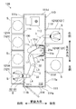
- FIG. 3 is a schematic plan view of the substrate processing equipment.
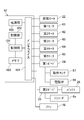
- FIG. 4 is a functional block diagram of the robot.
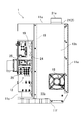
- FIG. 5 is a side view of the base with the first cover removed.
- FIG. 1 is a side view of the horizontal articulated robot 100.
- FIG. 2 is a plan view of the horizontal articulated robot 100.
- the horizontal articulated robot (hereinafter, also simply referred to as “robot”) 100 is a SCARA (SCARA: Selective Compliance Assembly Robot Arm) type robot.
- the robot 100 includes a base 1, an arm 3 rotatably connected to the base 1, and a hand 8 connected to the arm 3.
- the arm 3 is rotatably connected to the base 1 so as to be rotatable in the horizontal direction, that is, rotatably about the first axis L1 extending in the vertical direction.
- the arm 3 is composed of a plurality of links 30 that are rotatably connected to each other in the horizontal direction.
- the hand 8 is rotatably connected to the arm 3 in the horizontal direction.
- Hand 8 holds the object.
- the object is the substrate S.
- the robot 100 is an example of a robot.
- Hand 8 is an example of an end effector.
- the robot 100 further includes a control device 10 that controls the entire robot 100.
- FIG. 3 is a schematic plan view of the substrate processing equipment 120.
- the robot 100 is incorporated into, for example, a substrate transfer system 110 that conveys the substrate S.
- the board transfer system 110 includes a housing 111 and a robot 100.
- the substrate transfer system 110 is an EFEM (Equipment Front End Module).
- the substrate transfer system 110 conforms to the SEMI (Semiconductor Equipment and Materials International) standard.
- the configuration of the substrate transfer system 110 may be a configuration outside the SEMI standard.
- a transport space 112 is formed inside the housing 111.
- the robot 100 is arranged inside the housing 111, that is, in the transport space 112.
- the robot 100 transports the substrate S in the transport space 112.
- the substrate S is a disk-shaped semiconductor wafer.
- the transport space 112 is clean.
- the atmospheric gas that fills the transport space 112 is adjusted by a fan filter unit or the like.
- the transport space 112 is provided with an aligner 113 for aligning the substrate S.
- the housing 111 has a first side wall 111a and a third side wall 111c facing each other in a predetermined first direction, and a second side wall 111b and a fourth side wall 111d facing each other in a second direction different from the first direction. is doing.
- the first direction and the second direction intersect. More specifically, the first direction and the second direction are orthogonal to each other.
- the first direction is referred to as "front-back direction”
- the second direction is referred to as "left-right direction”.
- the front-back direction and the left-right direction are orthogonal to the up-down direction, respectively.
- the first side wall 111a and the second side wall 111b are adjacent to each other.
- the second side wall 111b and the third side wall 111c are adjacent to each other.
- the third side wall 111c and the fourth side wall 111d are adjacent to each other.
- the fourth side wall 111d and the first side wall 111a are adjacent to each other.
- the housing 111 is formed in a rectangular shape in a plan view, more specifically in a rectangular shape.
- the distance between the second side wall 111b and the fourth side wall 111d is larger than the distance between the first side wall 111a and the third side wall 111c. That is, the housing 111 is formed in a substantially rectangular shape that is longer in the left-right direction than in the front-rear direction in a plan view.
- the housing 111 further has a ceiling wall (not shown) and a bottom wall (not shown) facing each other in the vertical direction.
- the housing 111 is formed in a substantially rectangular parallelepiped shape.
- the substrate transfer system 110 is incorporated in the substrate processing equipment 120.
- the substrate processing equipment 120 includes a substrate transfer system 110 and a plurality of accommodating portions 121 for accommodating the substrate S.
- a storage chamber is formed inside the storage portion 121.
- the containment room is clean.
- the plurality of accommodating units 121 include a hoop (FOUP: Front Opening Unified Pod) 121A and a processing device 121B.
- the hoop 121A is a container for accommodating the substrate S.
- the processing device 121B processes the substrate S.
- the hoop 121A and the processing device 121B are arranged adjacent to the housing 111 outside the housing 111, respectively.
- the hoop 121A is arranged adjacent to one of the first side wall 111a and the third side wall 111c, and the processing device 121B is arranged adjacent to the other of the first side wall 111a and the third side wall 111c. Specifically, the hoop 121A is attached to the third side wall 111c via a hoop opener (not shown). The processing device 121B is arranged adjacent to the first side wall 111a.
- the hoop 121A is an example of a container for accommodating a semiconductor wafer.
- the substrate S before and after the treatment is housed in the hoop 121A.
- the hoop 121A is a substrate container for mini-environment.
- the hoop 121A accommodates a plurality of substrates S in a horizontal state at equal intervals in the vertical direction.
- four hoops 121A are provided.
- the four hoops 121A are arranged at equal intervals in the left-right direction.
- An opening 111e corresponding to the hoop 121A is formed in the third side wall 111c. The hoop opener switches the communication and blocking between the transport space 112 and the internal space of the hoop 121A.
- the processing device 121B is a processing device that performs, for example, heat treatment, impurity introduction treatment, thin film formation treatment, lithography treatment, cleaning treatment, flattening treatment, or appearance or dimensional inspection on the substrate S.
- the processing performed by the processing device 121B may be temporary accommodation for delivering the substrate S.
- two processing devices 121B are provided.
- An opening 111f corresponding to the processing device 121B is formed in the first side wall 111a.
- a door (not shown) may be provided in the opening 111f. By opening and closing the door, communication and blocking between the transport space 112 and the internal space of the processing device 121B can be switched.
- the robot 100 included in the substrate transfer system 110 transfers the semiconductor wafer between the hoop 121A for accommodating the semiconductor wafer and the processing device 121B for processing the semiconductor wafer.
- the hand 8 holds the semiconductor wafer as the substrate S.
- the arm 3 and the hand 8 convey the semiconductor wafer between the hoop 121A and the processing device 121B.
- the base 1 has a plurality of side portions (for example, side surfaces).
- the plurality of side portions include at least a first side portion 11a and a second side portion 11b that is not parallel to the first side portion 11a.
- the direction in which the first side portion 11a faces (that is, the normal direction of the first side portion 11a) and the direction in which the second side portion 11b faces (that is, the normal direction of the second side portion 11b) intersect. .. More specifically, the direction in which the first side portion 11a faces and the direction in which the second side portion 11b faces are orthogonal to each other.
- the plurality of side portions further include a third side portion 11c facing the first side portion 11a and a fourth side portion 11d facing the second side portion 11b.
- the first side portion 11a and the second side portion 11b are adjacent to each other.
- the second side portion 11b and the third side portion 11c are adjacent to each other.
- the third side portion 11c and the fourth side portion 11d are adjacent to each other.
- the fourth side portion 11d and the first side portion 11a are adjacent to each other.
- the base 1 is formed in a rectangular shape in a plan view, more specifically in a rectangular shape.
- the base 1 further has a ceiling portion 11e and a bottom portion 11f in addition to a plurality of side portions.
- the base 1 is formed in a substantially rectangular parallelepiped shape.
- the base 1 is provided with an elevating mechanism 2 for elevating and lowering the arm 3 in the vertical direction.
- the elevating mechanism 2 has a movable portion 21 and an elevating motor 22 for driving the movable portion 21.
- the movable portion 21 is formed in a columnar shape. In the state where the movable portion 21 is most lowered, most of the movable portion 21 is housed in the base 1.
- the movable portion 21 rises so as to project upward from the ceiling portion 11e of the base 1.
- the arm 3 is rotatably connected to the upper end portion 21a of the movable portion 21 in the horizontal direction. As shown by the solid line and the alternate long and short dash line in FIG. 1, the movable portion 21 moves up and down, and the arm 3 and the hand 8 move up and down accordingly.
- the connecting portion between the arm 3 and the base 1, that is, the upper end portion 21a of the movable portion 21, is arranged closest to the first side portion 11a among the plurality of side portions in a plan view. That is, the upper end portion 21a of the movable portion 21 is arranged offset from the center of the base 1 toward the first side portion 11a in a plan view.
- Each link 30 of the arm 3 is formed in a shape extending in a predetermined longitudinal direction.
- one end in the longitudinal direction is referred to as a first end
- the end opposite to the first end in the longitudinal direction is referred to as a second end.
- the three links 30 are distinguished from each other, they are referred to as a first link 31, a second link 32, and a third link 33 in order from the one closest to the base 1.
- the first link 31 is a link 30 connected to the base 1.
- a hand 8 is connected to the third link 33.
- the first end 31a of the first link 31 is rotatably connected to the base 1 about the first axial center L1 extending in the vertical direction. Specifically, the first end portion 31a is connected to the upper end portion 21a of the movable portion 21. That is, the first end portion 31a is a connecting portion with the base 1 of the arm 3.
- the first end portion 32a of the second link 32 is rotatably connected to the second end portion 31b of the first link 31 about the second axial center L2 extending in the vertical direction.
- the first end 33a of the third link 33 is rotatably connected to the second end 32b of the second link 32 about the third axial center L3 extending in the vertical direction.
- the first axis L1, the second axis L2, and the third axis L3 extend in parallel with each other.
- the length of the first link 31 (that is, the dimension in the longitudinal direction) is the longest of the three links 30.
- the robot 100 has two hands 8, that is, a first hand 8A and a second hand 8B (see FIG. 1).
- first hand 8A and the second hand 8B are not distinguished, they are simply referred to as "hand 8".
- the basic configurations of the first hand 8A and the second hand 8B are the same. In FIG. 2, since the two hands 8 are vertically overlapped with each other, only one hand 8 is apparently shown.
- Each hand 8 is rotatably connected to the second end 33b of the third link 33 about the fourth axis L4 extending in the vertical direction.
- the fourth axis L4 extends in parallel with the first axis L1, the second axis L2, and the third axis L3.
- the first link 31, the second link 32, the third link 33, the first hand 8A, and the second hand 8B are stacked in this order from bottom to top without contacting each other.
- the first link 31, the second link 32, the third link 33, and the two hands 8 rotate in the horizontal direction without interfering with each other.
- the robot 100 further includes a plurality of motors 6 for rotationally driving a plurality of links 30 and a hand 8.
- the plurality of motors 6 include a first motor 61 that rotationally drives the first link 31, a second motor 62 that rotationally drives the second link 32, and a third motor 63 that rotationally drives the third link 33. It includes a fourth motor 64 that rotationally drives the one hand 8A, and a fifth motor 65 that rotationally drives the second hand 8B.
- each motor 6 is an electric motor, specifically a servomotor.
- Each motor 6 has an encoder 6a that detects the rotation position or the amount of rotation of the rotation shaft.
- the link 30 is formed in a hollow shape and has an internal space.
- the motor 6 is housed in the internal space of the link 30.
- the first motor 61 and the second motor 62 are housed in the internal space of the first link 31.
- the third motor 63 is housed in the internal space of the second link 32.
- the fourth motor 64 and the fifth motor 65 are housed in the internal space of the third link 33.
- Each link 30 is provided with a transmission mechanism (not shown) for transmitting the power of each motor 6 together with each motor 6.
- the hand 8 has a main body 81 and a holding portion 82 connected to the main body 81 and divided into two branches.
- the hand 8 is formed in a plate shape.
- the hand 8 is formed in a substantially Y shape when viewed in the thickness direction thereof.
- the main body 81 is rotatably connected to the second end 33b of the third link 33.
- the hand 8 has a holding actuator (not shown) such as an air cylinder. The holding actuator switches between holding and releasing the object by the hand 8.
- Holding by the hand 8 can be realized in various modes such as gripping, suction, mounting or fitting.
- the hand 8 is configured to grip the substrate S as an object.
- the first claw 84 is fixedly provided on each of the two tip portions of the holding portion 82.
- the main body 81 is provided with a movable second claw 85 and a holding actuator 86 for driving the second claw 85.
- the holding actuator 86 is an air cylinder having a sleeve 86a and a rod 86b that advances and retreats from the sleeve 86a.
- the second claw 85 is connected to the rod 86b.
- the piping is provided with a solenoid valve 88 (see FIG. 1). The air supply is controlled by the solenoid valve 88.
- the second claw 85 moves in the direction approaching the first claw 84.
- the rod 86b retracts to the sleeve 86a
- the second claw 85 moves away from the first claw 84.
- the first claw 84 and the second claw 85 engage with the edge of the substrate S.
- the hand 8 holds the substrate S.
- the second claw 85 is separated from the edge of the substrate S.
- the hand 8 releases the substrate S.
- the main body 81 is provided with an operation sensor 87 that detects the operation of the second claw 85.
- the motion sensor 87 is a contact type or non-contact type sensor, and detects the motion of the second claw 85 by detecting the motion of the detected portion that moves integrally with the second claw 85 or the rod 86b.
- sensors other than the motion sensor 87 are also provided on the hand 8.
- a mapping sensor for detecting the state of the semiconductor wafer in the hoop 121A may be provided at the tip of the holding portion 82.
- a sensor for detecting the presence / absence of the semiconductor wafer on the holding unit 82 may be provided in the holding unit 82.
- the base 1 houses parts related to the control of at least one of the arm 3 and the hand 8 (hereinafter, referred to as "control parts").
- the base 1 includes a first board 24 that functions as an interface between a sensor such as an operation sensor 87 and a solenoid valve 88 and a control device 10, a second board 25 for supplying power to an encoder of a motor 6, and a second board 25. It houses a battery 26 and the like that supply electric power for holding the value of the encoder 6a when the main power supply is off.
- the first board 24 and the second board 25 are printed circuit boards.
- the second board 25 supplies the electric power from the battery 26 to the encoder 6a.
- the elevating motor 22 is also one of the control parts.
- the base 1 is closer to the first side wall 111a than the third side wall 111c in the front-rear direction in the housing 111, that is, the first side wall 111a is closer to the center of the housing 111 than the center. It is arranged offset toward the direction. In the left-right direction, the base 1 is arranged substantially in the center of the housing 111. In this way, by arranging the base 1 offset from the center of the housing 111 toward the first side wall 111a in the front-rear direction, the length of each link 30 is lengthened and the hand 8 is movable. The range is expanding.
- the first side portion 11a of the base 1 faces the first side wall 111a.
- the connecting portion between the arm 3 and the base 1 is arranged closer to the first side wall 111a.
- the length of each link 30 is further increased to further expand the movable range of the hand 8.
- the second side portion 11b of the base 1 faces the second side wall 111b
- the third side portion 11c of the base 1 faces the third side wall 111c
- the base 1 The fourth side portion 11d of the above faces the fourth side wall 111d.
- FIG. 4 is a functional block diagram of the robot 100.
- the control device 10 includes a control unit 101 that performs overall control of the robot 100, a storage unit 102 that stores various programs and various data, a memory 103, and an interface 104 that is connected to a motor 6 or the like. It has a power supply unit 105 for supplying electric power.
- the control device 10 is arranged outside the housing 111.
- the storage unit 102 is a recording medium that can be read by a computer, and is composed of, for example, a flash memory.
- the storage unit 102 may be composed of an optical disk such as a CD-ROM.
- the storage unit 102 stores various programs and various data necessary for executing the processing of the control unit 101.
- the control unit 101 controls the motor 6 and the like based on the program stored in the storage unit 102.
- the control unit 101 is composed of a processor such as a CPU (Central Processing Unit), for example.
- the control unit 101 executes various processes by expanding the program stored in the storage unit 102 or the like into the memory 103 and executing the program.
- the control unit 101 may be realized by hardware such as an LSI (Large Scale Integration) having the same function as the processor.
- An elevating motor 22, a first motor 61, a second motor 62, a third motor 63, a fourth motor 64, and a fifth motor 65 are connected to the interface 104.
- the first board 24 and the second board 25 are also connected to the interface 104.
- a fan 18 is also connected to the interface 104.
- Various sensors such as the motion sensor 87 and the solenoid valve 88 are connected to the first board 24.
- a battery 26 is connected to the second board 25, and each encoder 6a is connected to the second board 25.
- the control device 10 controls the motor 6 and the like in accordance with a predetermined operation program or an operation command input from the user to control the robot 100.
- the control device 10 controls the elevating motor 22 and / or the motor 6 to displace the arm 3. Further, the control device 10 controls the solenoid valve 88 via the first board 24 to cause the hand 8 to hold or release the substrate S. At this time, the detection result of the motion sensor 87 is input to the control device 10. Further, the control device 10 controls the second board 25 to supply electric power to the encoder 6a. When the main power supply of the robot 100 is off, the value of the encoder 6a is maintained by supplying the power supply to the encoder 6a by the second board 25.
- the control device 10 displaces the arm 3 and the hand 8 to allow the hand 8 to enter the internal space of the hoop 121A (see the solid line in FIG. 3). Then, the control device 10 causes the hand 8 to hold the substrate S in the hoop 121A. The control device 10 causes the hand 8 holding the substrate S to exit from the hoop 121A to the transport space 112 and further to enter the processing device 121B (see the alternate long and short dash line in FIG. 3). The control device 10 causes the hand 8 to release the substrate S at a predetermined position in the processing device 121B. After that, the control device 10 temporarily ejects the hand 8 from the processing device 121B.
- the control device 10 causes the hand 8 to enter the processing device 121B and causes the hand 8 to hold the substrate S.
- the control device 10 causes the hand 8 holding the substrate S to exit from the processing device 121B into the transport space 112, and further enters the hoop 121A.
- the control device 10 causes the hand 8 to release the substrate S at a predetermined position of the hoop 121A. In this way, the control device 10 causes the robot 100 to convey the substrate S between the hoop 121A and the processing device 121B.
- FIG. 5 is a side view of the base 1, showing a state in which the first cover 13a is removed.
- maintenance is performed on at least a part of the control parts (hereinafter, referred to as “maintenance parts”) on the second side portion 11b of the base 1.
- a maintenance unit 12 is provided for performing the above. Maintenance parts are arranged in the maintenance unit 12.
- the maintenance unit 12 is provided to perform maintenance of parts without moving the base 1, that is, with the base 1 installed on the spot. Maintenance parts are parts that are subject to such maintenance.
- maintenance parts are parts that are frequently maintained.
- maintenance parts are electrical parts.
- the first board 24, the second board 25, and the battery 26 are arranged in the maintenance unit 12 as maintenance parts.
- the maintenance unit 12 is provided in a portion of the second side portion 11b that is relatively close to the third side portion 11c.
- a first cover 13a that covers the maintenance portion 12 is detachably attached to the second side portion 11b (see FIG. 1).
- the first cover 13a is attached to the frame 19 of the base 1. By removing the first cover 13a, the maintenance unit 12 appears.
- the first cover 13a is an example of a cover.
- an elevating mechanism 2 is provided in the portion of the base 1 near the first side portion 11a. There is. Therefore, in the base 1, there is a margin of space in the portion closer to the third side portion 11c than in the portion closer to the first side portion 11a. Also in the second side portion 11b, it is easy to secure a space for arranging the maintenance portion 12 in a portion close to the third side portion 11c.
- the second cover 13b is attached to the frame 19.
- the second cover 13b covers the portion of the second side portion 11b that is close to the first side portion 11a.
- parts other than the maintenance parts for example, the elevating mechanism 2 and the like.
- the second cover 13b is removed.
- the base 1 is moved from the installation location to the maintenance location.
- the base 1 has a fan 18 that discharges the air inside the base 1 to the outside of the base 1.
- the fan 18 discharges the air in the base 1 in order to smoothly raise and lower the movable portion 21.
- Fans 18 are provided on the second side portion 11b and the fourth side portion 11d. Although the illustration of the fan 18 of the fourth side portion 11d is omitted, the fan 18 in the second side portion 11b is attached to a portion of the second side portion 11b other than the first cover 13a, specifically, the second cover 13b. It is attached.
- the second side portion 11b faces the second side wall 111b of the housing 111.
- the second side wall 111b is provided with an opening / closing portion 114 for maintaining the robot 100.
- an opening 114a is formed in the second side wall 111b, and a door for opening and closing the opening 114a is provided as an opening / closing portion 114.
- the opening 114a has a size that allows an operator to pass through.
- the opening / closing portion 114 is opened to enter the housing 111. Then, the operator removes the first cover 13a to expose the maintenance unit 12. After that, necessary maintenance is performed on the maintenance parts.
- the side portions of the base 1 other than the first side portion 11a which is close to the side wall of the housing 111 and faces the second side wall 111b on which the opening / closing portion 114 is formed.
- the robot so that the connecting portion between the arm 3 and the base 1 approaches the first side wall 111a in order to expand the movable range of the arm 3 and the hand 8 in the restricted transport space 112 in the housing 111.
- the base 1 is arranged so that the first side portion 11a of the side portions of the base 1 where the connecting portion between the arm 3 and the base 1 is closest to each other faces the first side wall 111a. Since the first side portion 11a is close to the first side wall 111a of the housing 111, it is difficult to secure a space for maintenance when the maintenance component is arranged on the first side portion 11a.
- the second side portion 11b faces the second side wall 111b of the housing 111.
- the second side wall 111b is provided with an opening / closing portion 114 for maintaining the robot 100.
- the housing 111 is formed in a substantially rectangular shape that is long in the left-right direction in a plan view, the space in the front-rear direction is narrow.
- a fan 18 is provided on the second side portion 11b in order to discharge air from the second side portion 11b to the outside. If the fan 18 is attached to the first cover 13a, the fan 18 moves together with the first cover 13a when the first cover 13a is removed. Wiring is connected to the fan 18. Since the fan 18 and its wiring are integrated with the removed first cover 13a, the handling of the first cover 13a becomes complicated.
- the first cover 13a is configured not to cover the entire surface of the second side portion 11b, but to cover only a part including the maintenance portion 12, and the fan 18 is configured to cover a portion other than the first cover 13a, that is, It is provided on the second cover 13b. As a result, the first cover 13a can be removed while the fan 18 remains as it is. This simplifies the handling of the first cover 13a and further improves maintainability.
- the robot 100 includes a base 1 having a plurality of side portions, an arm 3 rotatably connected to the base 1, and a hand 8 (end effector) connected to the arm 3.
- the first end portion 31a of the first link 31 and the upper end portion 21a (connecting portion between the arm and the base) of the movable portion 21 are the first side portion which is one side portion of the plurality of side portions in a plan view.
- the base 1 houses a control component (a component related to the control of at least one of the arm and end effector) and is not parallel to the first side portion 11a of the plurality of side portions.
- the second side portion 11b is provided with a maintenance portion 12 for performing maintenance on the maintenance parts in which maintenance parts (at least a part of parts related to control) such as the first board 24 are arranged.
- the base 1 houses the control parts.
- the maintenance parts are arranged in the maintenance part 12 provided on the second side part 11b of the base 1.
- the connecting portion between the arm 3 and the base 1 is arranged close to the first side portion 11a.
- Such a robot 100 can be used by being arranged in a limited space so that the first side portion 11a faces and approaches a boundary (for example, the side wall of the housing 111) that divides the space. With such an arrangement, the length of the arm 3 (the length of each link 30 when the arm 3 is composed of a plurality of links 30) is increased, and the movable range of the arm 3 is expanded. be able to.
- the first side portion 11a can approach the side wall of the housing 111 or the like, it is difficult to secure a space in a place facing the first side portion 11a.
- the second side portion 11b provided with the maintenance portion 12 is not parallel to the first side portion 11a and faces a different direction from the first side portion 11a, so that the second side portion 11b faces the second side portion 11b. It is easy to secure space in the place where you want to do it. That is, it becomes easy to secure a space for performing maintenance in the maintenance unit 12. As a result, the maintainability of the robot 100 in the limited space can be improved.
- the substrate transfer system 110 includes a housing 111 and a robot 100 arranged in the housing 111 to transport the substrate S, and the housing 111 is in the front-rear direction (predetermined first direction). ), The first side wall 111a and the third side wall 111c are opposed to each other, and the second side wall 111b and the fourth side wall 111d are opposed to each other in the left-right direction (second direction), which is different from the front-rear direction. Is provided with an opening / closing portion 114 for maintaining the robot 100, and the robot 100 is connected to a base 1 having a plurality of side portions, an arm 3 rotatably connected to the base 1, and an arm 3.
- the base 1 accommodates a control component (a component related to the control of at least one of the arm and the end effector) and has a first side wall 111a rather than a third side wall 111c.
- the first side portion 11a which is arranged close to the base 1 and is one of the plurality of side portions of the base 1, faces the first side wall 111a, and is located on the plurality of side portions of the base 1.
- Maintenance parts such as the first board 24 (at least a part of parts related to control) are arranged on the second side portion 11b facing the second side wall 111b, for performing maintenance on the maintenance parts.
- a maintenance unit 12 is provided.
- the robot 100 is arranged in the housing 111, and the base 1 is arranged close to the first side wall 111a of the housing 111.
- the base 1 houses the control parts.
- the maintenance parts are arranged in the maintenance part 12 provided on the second side part 11b of the base 1.
- the second side portion 11b faces the second side wall 111b of the housing 111.
- the second side wall 111b is provided with an opening / closing portion 114 for maintaining the robot 100. Therefore, when the operator opens the opening / closing portion 114 of the housing 111, he / she can easily access the maintenance portion 12 of the base 1 to maintain the maintenance parts. As a result, the maintainability of the robot 100 can be improved in the limited space in the housing 111. Further, since it is not necessary to provide a space for maintenance in the front-rear direction of the base 1, the dimensions of the housing 111 in the front-rear direction can be reduced.
- the housing 111 is formed in a quadrangular shape in a plan view.
- the distance between the second side wall 111b and the fourth side wall 111d is larger than the distance between the first side wall 111a and the third side wall 111c.
- the space inside the housing 111 is wider in the left-right direction than in the front-rear direction, it is easy to secure a space in the left-right direction of the base 1.
- the second side portion 11b faces the second side wall 111b, that is, in the left-right direction. Therefore, maintenance of maintenance parts can be performed using the space in the left-right direction of the base 1. As a result, the space inside the housing 111 can be effectively utilized to improve maintainability.
- the first end portion 31a of the arm 3 and the upper end portion 21a of the movable portion 21 are arranged closest to the first side portion 11a among the plurality of side portions in a plan view. Has been done.
- the first side portion 11a faces the first side wall 111a of the housing 111 to which the base 1 is close, the first end portion 31a of the arm 3 is the first side wall. It will be placed close to 111a.
- the length of the arm 3 (the length of each link 30 when the arm 3 is composed of a plurality of links 30) can be increased to expand the movable range of the arm 3.
- the plurality of side portions of the base 1 are the first side portion 11a, the second side portion 11b, the third side portion 11c facing the first side portion 11a, and the second side portion 11b facing the second side portion 11b.
- the base 1 is formed in a quadrangular shape in a plan view, including the four side portions 11d.
- the base 1 is substantially surrounded by a first side portion 11a and a third side portion 11c facing each other and a second side portion 11b and a fourth side portion 11d facing each other in a plan view. It is formed in a square shape.
- the parts arranged in the maintenance unit 12 are electrical parts.
- the base 1 is provided on the second side portion 11b and has a fan 18 for discharging the air inside the base 1, and the second side portion 11b has a first cover 13a (which covers the maintenance portion 12).
- the cover is detachably attached, and the fan 18 is arranged in a portion of the second side portion 11b other than the first cover 13a.
- the first cover 13a is removed when the maintenance unit 12 performs maintenance. Since the fan 18 is arranged in a portion other than the first cover 13a, the fan 18 remains arranged in the second side portion 11b even if the first cover 13a is removed. This facilitates the handling of the first cover 13a and improves maintainability.
- a hand 8 that holds the substrate S is adopted.
- the robot 100 conveys the substrate S.
- the transfer of the substrate S is often performed in a clean space such as in the housing 111. That is, the robot 100 is often used in a limited space. In such a usage situation, it is particularly effective to improve maintainability by the above-mentioned configuration.
- a hoop 121A (container) for accommodating a semiconductor wafer is arranged adjacent to the first side wall 111a (one of the first side wall and the third side wall), and the third side wall 111c (the other of the first side wall and the third side wall).
- a processing device 121B for processing the semiconductor wafer is arranged adjacent to the robot 100, the hand 8 holds the semiconductor wafer as the substrate S, and the robot 100 conveys the semiconductor wafer between the hoop 121A and the processing device 121B. ..
- the robot 100 is incorporated in the substrate transfer system 110, but is not limited thereto.
- the robot 100 is not limited to use in a clean environment capable of processing semiconductors.
- the robot 100 may be incorporated in a production line or the like.
- the robot 100 is arranged and used in a limited space such as the housing 111.
- the board transfer system 110 does not have to be incorporated in the board processing equipment 120. That is, the substrate transfer system 110 may adopt any configuration as long as the robot 100 conveys the substrate S in the housing 111.
- the moving source and moving destination of the substrate S are not limited to the hoop 121A and the processing device 121B.
- the substrate S can be a thin plate that is a material for a substrate of a semiconductor device such as a semiconductor substrate and a glass substrate.
- the semiconductor substrate include a silicon substrate and a sapphire substrate.
- the glass substrate include a glass substrate for FPD (Flat Panel Display), a glass substrate for MEMS (Micro Electro Mechanical Systems), and the like.
- the hoop 121A may be arranged adjacent to the first side wall 111a, and the processing device 121B may be arranged adjacent to the third side wall 111c. Further, the hoop 121A or the processing device 121B may be arranged adjacent to the second side wall 111b or the fourth side wall 111d.
- the configuration of the housing 111 is not limited to the above-mentioned configuration.
- the housing 111 may be formed in a shape other than a quadrangular shape in a plan view.
- the housing 111 may have one or more other side walls in addition to the first side wall 111a and the third side wall 111c facing each other and the second side wall 111b and the fourth side wall 111d facing each other. good.
- the first side wall 111a and the second side wall 111b may not be directly connected to each other, but may be connected via one or more other side walls.
- the distance between the first side wall 111a and the third side wall 111c may be larger than the distance between the second side wall 111b and the fourth side wall 111d.
- the direction in which the first side wall 111a faces and the direction in which the second side wall 111b faces may intersect at an angle other than 90 degrees.
- the opening / closing part 114 is not limited to the door.
- the opening / closing portion 114 can be attached to and detached from the housing 111, and may be completely removed from the housing 111 when the opening 114a is opened.
- the robot is not limited to the horizontal articulated robot 100.
- the robot may be a vertical articulated robot.
- the arm 3 does not have to be composed of a plurality of links 30.
- the number of divisions of the arm 3, that is, the number of links 30, is not limited to 3.
- the arm 3 may be composed of two or four or more links 30.
- the connecting portion between the arm 3 and the base 1 does not have to be closest to the first side portion 11a among the plurality of side portions of the base 1.
- the connecting portion may be closest to the second side portion 11b of the plurality of side portions.
- the connecting portion may be arranged at the center of the base 1 in a plan view.
- the end effector is not limited to hand 8.
- the end effector may be a painting tool or a welding tool. Even when the end effector is the hand 8, the object held by the hand 8 is not limited to the substrate.
- the number of hands 8 (that is, the number of end effectors) is not limited to two, and may be one or three or more.
- the configuration of the base 1 is not limited to the above-mentioned configuration.
- the base 1 may be formed in a shape other than a quadrangular shape in a plan view.
- the base 1 has one or more other side portions in addition to the first side portion 11a and the third side portion 11c facing each other and the second side portion 11b and the fourth side portion 11d facing each other. You may have.
- the first side portion 11a and the second side portion 11b may not be directly connected to each other but may be connected via one or a plurality of other side portions.
- the direction in which the first side portion 11a faces and the direction in which the second side portion 11b faces may intersect at an angle other than 90 degrees.
- the maintenance unit 12 can be arranged at any place as long as it is the second side unit 11b.
- the maintenance unit 12 may be provided in a portion of the second side portion 11b that is close to the first side portion 11a. Further, the maintenance unit 12 may be provided on the entire second side portion 11b.
- the maintenance unit 12 is covered with the first cover 13a, but the first cover 13a may be absent and exposed. Further, the first cover 13a may be attached to the base 1 so as to open and close the maintenance unit 12 like a hinged door.
- the parts arranged in the maintenance unit 12 may be parts other than the first board 24, the second board 25, and the battery 26.
- the sensors provided on the hand 8 in the above configuration such as the motion sensor 87
- those sensors may be arranged in the maintenance unit 12 as maintenance parts.
- an optical fiber is laid in the arm 3 from the sensor arranged in the maintenance unit 12 to the hand 8.
- the solenoid valve 88 may be arranged in the maintenance unit 12 as a maintenance component instead of inside the arm 3.
- control device 10 may be housed in the base 1.
- a board including the control unit 101 and the like of the control device 10 may be arranged in the maintenance unit 12 as a maintenance component.
- the electrolytic capacitor that serves as the power source for the control device 10 may also be housed in the base 1.
- the electrolytic capacitor may also be arranged in the maintenance unit 12 as a maintenance component.
- a pipe for sucking air from the suction portion of the hand 8 is provided.
- the pipe may be provided with a solenoid valve that switches the flow and shutoff of air in the pipe, and a pressure sensor that detects the pressure in the pipe.
- These solenoid valves or pressure sensors may be arranged in the maintenance unit 12 as maintenance parts.
- the technology disclosed here is useful for robots and substrate transfer systems equipped with them.
Landscapes
- Engineering & Computer Science (AREA)
- Mechanical Engineering (AREA)
- Robotics (AREA)
- Manipulator (AREA)
- Container, Conveyance, Adherence, Positioning, Of Wafer (AREA)
- Warehouses Or Storage Devices (AREA)
Abstract
ロボット100は、複数の側部を有する基台1と、基台1に回転可能に連結されたアーム3と、アーム3に連結されたハンド8とを備えている。アーム3と基台1との連結部分は、平面視で、第1側部11aに最も接近して配置されている。基台1は、制御部品を収容している。第2側部11bには、第1ボード24等のメンテナンス部品が配置された、メンテナンス部品にメンテナンスを行うためのメンテナンス部12が設けられている。
Description
ここに開示された技術は、ロボット及びそれを備えた基板搬送システムに関する。
従来より、基台とアームとエンドエフェクタとを備えたロボットが知られている。例えば、特許文献1には、基台と、基台に回転可能に連結されたアームと、アームに連結されたエンドエフェクタとを備え、筐体内に配置されるロボットが開示されている。このロボットでは、基台の一部が筐体外に配置されている。これにより、基台のうち筐体外に出された部分のメンテナンス性を向上させている。
このように、ロボットは筐体等の内部に配置されて使用される場合がある。そのような場合、筐体等の内部のスペースは制限されているため、ロボットのメンテナンスが難しくなる。
特許文献1のようにロボットの一部を筐体外に配置することもメンテナンス性向上の対応策の1つではあるが、筐体内などの制限されたスペース内でのメンテナンス性の向上にもまだ改善の余地が残されている。
ここに開示された技術は、かかる点に鑑みてなされたものであり、その目的とするところは、制限されたスペース内でのロボットのメンテナンス性を向上させることにある。
ここに開示されたロボットは、複数の側部を有する基台と、前記基台に回転可能に連結されたアームと、前記アームに連結されたエンドエフェクタとを備え、前記アームと前記基台との連結部分は、平面視で、前記複数の側部のうち一の側部である第1側部に最も接近して配置され、前記基台は、前記アーム及び前記エンドエフェクタの少なくとも一方の制御に関連する部品を収容し、前記複数の側部のうち前記第1側部と平行でない第2側部には、前記部品の少なくとも一部の部品が配置された、前記少なくとも一部の部品にメンテナンスを行うためのメンテナンス部が設けられている。
ここに開示された基板搬送システムは、筐体と、前記筐体内に配置されて基板を搬送するロボットとを備え、前記筐体は、所定の第1方向において対向する第1側壁及び第3側壁と、前記第1方向と異なる方向である第2方向において対向する第2側壁及び第4側壁とを有し、前記第2側壁には、前記ロボットをメンテナンスするための開閉部が設けられ、前記ロボットは、複数の側部を有する基台と、前記基台に回転可能に連結されたアームと、前記アームに連結されたエンドエフェクタとを有し、前記基台は、前記アーム及び前記エンドエフェクタの少なくとも一方の制御に関連する部品を収容すると共に、前記第3側壁よりも前記第1側壁に接近して配置され、前記基台の前記複数の側部のうちの一の側部である第1側部は、前記第1側壁と対向しており、前記基台の前記複数の側部のうち前記第2側壁の方を向く第2側部には、前記部品の少なくとも一部の部品が配置された、前記少なくとも一部の部品にメンテナンスを行うためのメンテナンス部が設けられている。
前記ロボットによれば、制限されたスペース内でのロボットのメンテナンス性を向上させることができる。
前記基板搬送システムによれば、制限されたスペース内でのロボットのメンテナンス性を向上させることができる。
以下、例示的な実施形態を図面に基づいて詳細に説明する。
図1は、水平多関節ロボット100の側面図である。図2は、水平多関節ロボット100の平面図である。水平多関節ロボット(以下、単に「ロボット」ともいう)100は、スカラ(SCARA: Selective Compliance Assembly Robot Arm)型のロボットである。ロボット100は、基台1と、基台1に回転可能に連結されたアーム3と、アーム3に連結されたハンド8とを備えている。アーム3は、水平方向に回転可能に、即ち、鉛直方向に延びる第1軸心L1を中心に回転可能に基台1に連結されている。アーム3は、互いに水平方向に回転可能に連結された複数のリンク30で構成されている。ハンド8は、水平方向に回転可能にアーム3に連結されている。ハンド8は、対象物を保持する。例えば、対象物は、基板Sである。ロボット100は、ロボットの一例である。ハンド8は、エンドエフェクタの一例である。ロボット100は、ロボット100の全体的な制御を行う制御装置10をさらに備えている。
図3は、基板処理設備120の概略的な平面図である。ロボット100は、例えば、基板Sを搬送する基板搬送システム110に組み込まれる。基板搬送システム110は、筐体111と、ロボット100とを有している。例えば、基板搬送システム110は、EFEM(Equipment Front End Module)である。基板搬送システム110は、SEMI(Semiconductor Equipment and Materials International)規格に準拠する。尚、基板搬送システム110の構成は、SEMI規格外の構成であってもよい。
筐体111の内部には、搬送空間112が形成されている。ロボット100は、筐体111の内部、即ち、搬送空間112に配置されている。ロボット100は、搬送空間112において、基板Sを搬送する。例えば、基板Sは、円盤状の半導体ウェハである。搬送空間112は、クリーン化されている。搬送空間112を満たす雰囲気気体は、ファンフィルタユニット等によって調整される。搬送空間112には、基板Sの位置合わせを行うアライナ113が設けられている。
筐体111は、所定の第1方向において対向する第1側壁111a及び第3側壁111cと、第1方向と異なる方向である第2方向において対向する第2側壁111b及び第4側壁111dとを有している。第1方向と第2方向とは、交差している。より具体的には、第1方向と第2方向とは、直交している。以下、説明の便宜上、第1方向を「前後方向」と称し、第2方向を「左右方向」と称する。前後方向及び左右方向はそれぞれ、上下方向と直交している。第1側壁111aと第2側壁111bとは、隣接している。第2側壁111bと第3側壁111cとは、隣接している。第3側壁111cと第4側壁111dとは、隣接している。第4側壁111dと第1側壁111aとは、隣接している。筐体111は、平面視で四角形状、より具体的には長方形状に形成されている。
第2側壁111bと第4側壁111dとの間隔は、第1側壁111aと第3側壁111cとの間隔よりも大きい。つまり、筐体111は、平面視で、前後方向よりも左右方向に長い略長方形状に形成されている。
筐体111は、上下方向に対向する天井壁(図示省略)及び底壁(図示省略)とをさらに有している。筐体111は、略直方体状に形成されている。
例えば、基板搬送システム110は、基板処理設備120に組み込まれている。基板処理設備120は、基板搬送システム110と、基板Sを収容する複数の収容部121とを有している。収容部121の内部には、収容室が形成されている。収容室は、クリーン化されている。例えば、複数の収容部121は、フープ(FOUP: Front Opening Unified Pod)121Aと処理装置121Bとを含んでいる。フープ121Aは、基板Sを収容する容器である。処理装置121Bは、基板Sを処理する。フープ121A及び処理装置121Bはそれぞれ、筐体111の外部において筐体111に隣接して配置されている。第1側壁111a及び第3側壁111cの一方には、フープ121Aが隣接して配置され、第1側壁111a及び第3側壁111cの他方には、処理装置121Bが隣接して配置される。具体的には、フープ121Aは、フープオープナ(図示省略)を介して第3側壁111cに取り付けられている。処理装置121Bは、第1側壁111aに隣接して配置されている。フープ121Aは、半導体ウェハを収容する容器の一例である。
フープ121A内には、処理前及び処理後の基板Sが収容される。フープ121Aは、ミニエンバイロメント用基板容器である。フープ121Aは、複数の基板Sを水平な状態で鉛直方向に等間隔を開けて収容する。この例では、4個のフープ121Aが設けられている。4個のフープ121Aは、左右方向に等間隔に配置されている。第3側壁111cには、フープ121Aに対応する開口111eが形成されている。フープオープナによって、搬送空間112とフープ121Aの内部空間との連通及び遮断が切り替えられる。
処理装置121Bは、例えば、熱処理、不純物導入処理、薄膜形成処理、リソグラフィ処理、洗浄処理、平坦化処理又は外観若しくは寸法の検査を基板Sに行う処理装置である。あるいは、処理装置121Bが行う処理は、基板Sの受け渡しを行うための一時的な収容であってもよい。この例では、2個の処理装置121Bが設けられている。第1側壁111aには、処理装置121Bに対応する開口111fが形成されている。開口111fにはドア(図示省略)が設けられてもよい。ドアの開閉によって、搬送空間112と処理装置121Bの内部空間との連通及び遮断が切り替えられる。
このような構成においては、基板搬送システム110に含まれるロボット100は、半導体ウェハを収容するフープ121Aと半導体ウェハを処理する処理装置121Bとの間で半導体ウェハを搬送する。具体的には、ハンド8は、基板Sとして半導体ウェハを保持する。アーム3及びハンド8は、フープ121Aと処理装置121Bとの間で半導体ウェハを搬送する。
〈ロボット100の構成〉
ロボット100の構成について図1,2を参照しながら説明する。
ロボット100の構成について図1,2を参照しながら説明する。
基台1は、複数の側部(例えば、側面)を有している。複数の側部には、第1側部11aと、第1側部11aと平行でない第2側部11bとが少なくとも含まれている。第1側部11aの向く方向(即ち、第1側部11aの法線方向)と第2側部11bの向く方向(即ち、第2側部11bの法線方向)とは、交差している。より具体的には、第1側部11aの向く方向と第2側部11bの向く方向とは、直交している。複数の側部には、第1側部11aと対向する第3側部11cと、第2側部11bと対向する第4側部11dとがさらに含まれている。第1側部11aと第2側部11bとは、隣接している。第2側部11bと第3側部11cとは、隣接している。第3側部11cと第4側部11dとは、隣接している。第4側部11dと第1側部11aとは、隣接している。基台1は、平面視で四角形状、より具体的には長方形状に形成されている。
基台1は、複数の側部に加えて、天井部11eと底部11fとをさらに有している。基台1は、略直方体状に形成されている。
基台1には、アーム3を鉛直方向に昇降させる昇降機構2が設けられている。昇降機構2は、可動部21と、可動部21を駆動する昇降モータ22とを有している。可動部21は、柱状に形成されている。可動部21が最も降下した状態においては、可動部21の大部分が基台1内に収容される。可動部21は、基台1の天井部11eから上方に突出するように上昇する。アーム3は、水平方向に回転可能に可動部21の上端部21aに連結されている。図1において実線及び二点鎖線で示すように、可動部21が上下動することによって、それに応じてアーム3及びハンド8が上下動する。
アーム3と基台1との連結部分、即ち、可動部21の上端部21aは、平面視で、複数の側部のうち第1側部11aに最も接近して配置されている。すなわち、可動部21の上端部21aは、平面視で、基台1の中心から第1側部11aの方へオフセットして配置されている。
アーム3の各リンク30は、所定の長手方向に延伸した形状に形成されている。以下、特に断りが無い限り、各リンク30において、長手方向における一端部を第1端部と称し、長手方向における第1端部とは反対側の端部を第2端部と称する。3本のリンク30をそれぞれ区別する場合には、基台1に近い方から順に、第1リンク31、第2リンク32、第3リンク33と称する。第1リンク31は、基台1に連結されたリンク30である。第3リンク33には、ハンド8が連結されている。
第1リンク31の第1端部31aは、鉛直方向に延びる第1軸心L1を中心に回転可能に基台1に連結されている。詳しくは、第1端部31aは、可動部21の上端部21aに連結されている。すなわち、第1端部31aは、アーム3のうちの基台1との連結部分である。第2リンク32の第1端部32aは、鉛直方向に延びる第2軸心L2を中心に回転可能に第1リンク31の第2端部31bに連結されている。第3リンク33の第1端部33aは、鉛直方向に延びる第3軸心L3を中心に回転可能に第2リンク32の第2端部32bに連結されている。第1軸心L1、第2軸心L2及び第3軸心L3は、互いに平行に延びている。第1リンク31の長さ(即ち、長手方向の寸法)は、3本のリンク30の中で最も長い。
ロボット100は、2つのハンド8、即ち、第1ハンド8A及び第2ハンド8Bを有している(図1参照)。第1ハンド8A及び第2ハンド8Bを区別しない場合には、単に「ハンド8」と称する。第1ハンド8A及び第2ハンド8Bの基本的な構成は同じである。尚、図2では、2つのハンド8が上下に重なっているため、見かけ上、ハンド8が1つだけ図示されている。
各ハンド8は、鉛直方向に延びる第4軸心L4を中心に回転可能に第3リンク33の第2端部33bに連結されている。第4軸心L4は、第1軸心L1、第2軸心L2及び第3軸心L3と平行に延びている。
第1リンク31、第2リンク32、第3リンク33、第1ハンド8A、第2ハンド8Bは、この順で下から上へ、互いに接触しない状態で積み上げられている。第1リンク31、第2リンク32、第3リンク33及び2つのハンド8は、互いに干渉することなく水平方向に回転する。
ロボット100は、複数のリンク30及びハンド8を回転駆動する複数のモータ6をさらに備えている。複数のモータ6には、第1リンク31を回転駆動する第1モータ61と、第2リンク32を回転駆動する第2モータ62と、第3リンク33を回転駆動する第3モータ63と、第1ハンド8Aを回転駆動する第4モータ64と、第2ハンド8Bを回転駆動する第5モータ65とを含んでいる。第1モータ61、第2モータ62、第3モータ63、第4モータ64及び第5モータ65のそれぞれを区別しない場合には、単に「モータ6」と称する。例えば、各モータ6は、電動モータ、具体的にはサーボモータである。各モータ6は、回転シャフトの回転位置又は回転量を検出するエンコーダ6aを有している。
リンク30は、中空状に形成され、内部空間を有している。モータ6は、リンク30の内部空間に収容されている。具体的には、第1モータ61及び第2モータ62は、第1リンク31の内部空間に収容される。第3モータ63は、第2リンク32の内部空間に収容される。第4モータ64及び第5モータ65は、第3リンク33の内部空間に収容される。尚、各リンク30には、各モータ6と共に、各モータ6の動力を伝達する伝達機構(図示省略)が設けられている。
ハンド8は、本体81と、本体81に連結され、二又状に分かれた保持部82とを有している。ハンド8は、板状に形成されている。ハンド8は、その厚み方向を向いて見た場合に、略Y字状に形成されている。本体81は、第3リンク33の第2端部33bに回転可能に連結されている。ハンド8は、エアシリンダ等の保持アクチュエータ(図示省略)を有している。保持アクチュエータによって、ハンド8による対象物の保持及び解放が切り替えられる。
ハンド8による保持は、把持、吸着、載置又は嵌合等、様々な態様で実現し得る。この例では、ハンド8は、対象物としての基板Sを把持するように構成されている。具体的には、保持部82の2つの先端部のそれぞれには第1爪84が固定的に設けられている。本体81には、移動可能な第2爪85と第2爪85を駆動する保持アクチュエータ86とが設けられている。
保持アクチュエータ86は、スリーブ86aとスリーブ86aから進退するロッド86bとを有するエアシリンダである。第2爪85は、ロッド86bに連結されている。アーム3の内部には、エアシリンダに圧縮エアを供給する配管が設けられている。配管には、電磁弁88(図1参照)が設けられている。エアの供給は、電磁弁88によって制御される。
ロッド86bがスリーブ86aから進出すると、第2爪85が第1爪84へ近づく方向へ移動する。一方、ロッド86bがスリーブ86aへ後退すると、第2爪85が第1爪84から離れる方向へ移動する。第1爪84と第2爪85との間に基板Sが位置する状態で第2爪85を進出させることによって、第1爪84及び第2爪85が基板Sの端縁に係合する。これにより、ハンド8が基板Sを保持する。この状態から第2爪85を後退させることによって、第2爪85が基板Sの端縁から離れる。これにより、ハンド8が基板Sを解放する。
本体81には、第2爪85の動作を検出する動作センサ87が設けられている。動作センサ87は、接触式又は非接触式のセンサであって、第2爪85又はロッド86bと一体的に移動する被検出部の動作を検出することによって第2爪85の動作を検出する。
尚、図示を省略するが、動作センサ87以外のセンサもハンド8に設けられている。例えば、フープ121A内での半導体ウェハの状態を検出するマッピングセンサが保持部82の先端部に設けられ得る。また、保持部82上の半導体ウェハの有無を検出するセンサが保持部82に設けられ得る。
基台1は、アーム3及びハンド8の少なくとも一方の制御に関連する部品(以下、「制御部品」という)を収容している。例えば、基台1は、動作センサ87等のセンサ及び電磁弁88と制御装置10とのインタフェイスとして機能する第1ボード24、モータ6のエンコーダに電源を供給するための第2ボード25、及び、主電源がオフの場合等にエンコーダ6aの値を保持しておくための電力を供給するバッテリ26等を収容している。第1ボード24及び第2ボード25は、プリント基板である。第2ボード25は、バッテリ26からの電力をエンコーダ6aに供給する。昇降モータ22も制御部品の1つである。
図3に示すように、基台1は、筐体111内の前後方向において、第3側壁111cよりも第1側壁111aに接近して、即ち、筐体111の中央よりも第1側壁111aの方へオフセットして配置されている。左右方向においては、基台1は、筐体111の略中央に配置されている。このように、基台1を、前後方向において、筐体111の中央よりも第1側壁111aの方へオフセットして配置することによって、各リンク30の長さを長くして、ハンド8の可動範囲を拡大している。
このとき、基台1の第1側部11aは、第1側壁111aと対向している。これにより、アーム3と基台1との連結部分が、第1側壁111aにより接近して配置されることになる。その結果、各リンク30の長さをさらに長くして、ハンド8の可動範囲をより拡大している。
このような配置とすることにより、基台1の第2側部11bは、第2側壁111bと対向し、基台1の第3側部11cは、第3側壁111cと対向し、基台1の第4側部11dは、第4側壁111dと対向している。
図4は、ロボット100の機能ブロック図である。制御装置10は、ロボット100の全体的な制御を行う制御部101と、各種プログラム及び各種データを記憶する記憶部102と、メモリ103と、モータ6等に接続されるインタフェイス104と、各部に電力を供給する電源部105とを有している。制御装置10は、筐体111の外部に配置される。
記憶部102は、コンピュータに読み取り可能な記録媒体であり、例えば、フラッシュメモリで構成されている。尚、記憶部102は、CD-ROM等の光ディスク等で構成されていてもよい。記憶部102は、制御部101の処理の実行に必要な各種プログラムや各種データを記憶している。
制御部101は、記憶部102に記憶されているプログラムに基づいてモータ6等を制御する。制御部101は、例えばCPU(Central Processing Unit)等のプロセッサで構成されている。制御部101は、記憶部102等に記憶されたプログラムをメモリ103に展開して実行することによって各種処理を実行する。尚、制御部101は、プロセッサと同様の機能を有するLSI(Large Scale Integration)等のハードウェアによって実現されてもよい。
インタフェイス104には、昇降モータ22、第1モータ61、第2モータ62、第3モータ63、第4モータ64及び第5モータ65が接続される。インタフェイス104には、第1ボード24及び第2ボード25も接続される。インタフェイス104には、ファン18も接続される。尚、第1ボード24には、動作センサ87等の各種センサ及び電磁弁88等が接続されている。第2ボード25には、バッテリ26が接続されると共に、各エンコーダ6aが接続されている。
制御装置10は、予め定められた動作プログラム又はユーザから入力される動作指令に従って、モータ6等を制御して、ロボット100を制御する。制御装置10は、昇降モータ22及び/又はモータ6を制御して、アーム3を変位させる。また、制御装置10は、第1ボード24を介して電磁弁88を制御して、ハンド8に基板Sを保持又は解放させる。このとき、制御装置10には、動作センサ87の検出結果が入力されている。さらに、制御装置10は、第2ボード25を制御して、エンコーダ6aへ電力を供給させる。尚、ロボット100の主電源がオフの場合には、第2ボード25がエンコーダ6aへ電源を供給することによって、エンコーダ6aの値が保持される。
例えば、制御装置10は、アーム3及びハンド8を変位させ、ハンド8をフープ121Aの内部空間に進入させる(図3の実線参照)。そして、制御装置10は、ハンド8にフープ121A内の基板Sを保持させる。制御装置10は、基板Sを保持した状態のハンド8をフープ121Aから搬送空間112へ退出させ、さらに、処理装置121Bへ進入させる(図3の二点鎖線参照)。制御装置10は、処理装置121B内の所定位置においてハンド8に基板Sを解放させる。その後、制御装置10は、ハンド8を処理装置121Bから一旦、退出させる。処理装置121Bでは、基板Sに所定の処理が施される。基板Sの処理後、制御装置10は、ハンド8を処理装置121Bへ進入させ、ハンド8に基板Sを保持させる。制御装置10は、基板Sを保持した状態のハンド8を処理装置121Bから搬送空間112へ退出させ、さらに、フープ121Aへ進入させる。制御装置10は、フープ121Aの所定位置においてハンド8に基板Sを解放させる。このように、制御装置10は、ロボット100にフープ121Aと処理装置121Bとの間で基板Sを搬送させる。
図5は、基台1の側面図であって、第1カバー13aを取り外した状態を示す。このように構成されたロボット100においては、図1,5に示すように、基台1の第2側部11bに、制御部品の少なくとも一部の部品(以下、「メンテナンス部品」という)にメンテナンスを行うためのメンテナンス部12が設けられている。メンテナンス部12には、メンテナンス部品が配置されている。メンテナンス部12は、基台1を動かすことなく、即ち、基台1をその場に設置したまま部品のメンテナンスを行うために設けられている。メンテナンス部品は、そのようなメンテナンスの対象となる部品である。
例えば、メンテナンス部品は、メンテナンス頻度が高い部品である。例えば、メンテナンス部品は、電気部品である。この例では、第1ボード24、第2ボード25及びバッテリ26がメンテナンス部品としてメンテナンス部12に配置されている。
メンテナンス部12は、第2側部11bのうち第3側部11cに比較的近い部分に設けられている。第2側部11bには、メンテナンス部12を覆う第1カバー13aが着脱可能に取り付けられている(図1参照)。第1カバー13aは、基台1のフレーム19に取り付けられている。第1カバー13aを取り外すことによって、メンテナンス部12が現れる。第1カバー13aは、カバーの一例である。
アーム3と基台1との連結部分が第1側部11aに接近して配置されているので、基台1の内部において第1側部11aに近い部分には、昇降機構2が設けられている。そのため、基台1においては、第1側部11aに近い部分よりも第3側部11cに近い部分にスペースの余裕がある。第2側部11bにおいても第3側部11cに近い部分に、メンテナンス部12を配置するスペースを確保しやすい。
第2側部11bでは、第1カバー13aの他に、第2カバー13bがフレーム19に取り付けられている。第2カバー13bは、第2側部11bのうち第1側部11aに近い部分を覆っている。第2カバー13bを取り外すと、メンテナンス部品以外の部品(例えば、昇降機構2等)が露出する。それらの部品のメンテナンスを行う場合には第2カバー13bが取り外される。しかし、第2カバー13bを取り外してメンテナンスを行う場合には、基台1がその設置場所からメンテナンスを行う場所まで移動させられる。
また、基台1は、基台1の内部の空気を基台1の外部へ排出するファン18を有している。ファン18は、昇降機構2が可動部21を昇降させる際に、可動部21の昇降を円滑に行うために、基台1内の空気を排出する。ファン18は、第2側部11b及び第4側部11dに設けられている。第4側部11dのファン18の図示は省略するが、第2側部11bにおけるファン18は、第2側部11bのうち第1カバー13a以外の部分、具体的には、第2カバー13bに取り付けられている。
第2側部11bは、図3に示すように、筐体111の第2側壁111bと対向している。第2側壁111bには、ロボット100をメンテナンスするための開閉部114が設けられている。詳しくは、第2側壁111bには、開口114aが形成され、開口114aを開閉するドアが開閉部114として設けられている。開口114aは、作業者が通ることができる程度の大きさを有している。
作業者がロボット100の第1ボード24等のメンテナンス部品をメンテナンスする際には、開閉部114を開けて筐体111内に進入する。そして、作業者は、第1カバー13aを取り外し、メンテナンス部12を露出させる。その後、メンテナンス部品に対して必要なメンテナンスを行う。
このように、基台1の側部のうち筐体111の側壁と接近している第1側部11a以外の側部であって、開閉部114が形成された第2側壁111bの方を向く第2側部11bにメンテナンス部12を設けることによって、ロボット100のメンテナンス性を向上させることができる。
詳しくは、筐体111内の制限された搬送空間112内においてアーム3及びハンド8の可動範囲を拡大すべく、アーム3と基台1との連結部分が第1側壁111aに接近するようにロボット100が配置される。さらには、基台1の側部のうちアーム3と基台1との連結部分が最も接近している第1側部11aが第1側壁111aと対向するように基台1が配置される。第1側部11aが筐体111の第1側壁111aと接近しているので、メンテナンス部品を第1側部11aに配置すると、メンテナンスのためのスペースを確保することが難しい。
基台1がこのように配置される結果、第2側部11bは、筐体111の第2側壁111bと対向することになる。第2側壁111bには、ロボット100をメンテナンスするための開閉部114が設けられている。第2側部11bにメンテナンス部12を設けることによって、開閉部114から筐体111内に進入した作業者がメンテナンス部12に容易にアクセスすることができる。その結果、ロボット100のメンテナンス部品のメンテナンス性を向上させることができる。
特に、筐体111は、平面視で左右方向に長い略長方形状に形成されているので、前後方向のスペースは狭小である。その一方で、基台1の左右方向にはスペースが存在する。基台1の第2側部11bにメンテナンス部12を設けることによって、筐体111内でメンテナンスのためのスペースを確保することができる。つまり、基台1の左右方向のスペースを有効に使ってメンテナンスを行うことができる。
別の観点からは、第2側壁111bと対向する第2側部11bにメンテナンス部12を設けることによって、基台1の前後方向にメンテナンスのためのスペースを確保する必要が無い。その結果、筐体111の前後方向の寸法を小型化することができる。ひいては、基板搬送システム110を小型化することができる。
さらに、第2側部11bから外方へ空気を排出するために第2側部11bにはファン18が設けられている。仮にファン18が第1カバー13aに取り付けられていると、第1カバー13aを取り外す際にファン18が第1カバー13aと共に移動する。ファン18には配線が接続されている。取り外した第1カバー13aにはファン18及びその配線が一体的になっているので、第1カバー13aの取り扱いが煩雑となる。それに対し、第1カバー13aは、第2側部11bの全面を覆うのではなく、メンテナンス部12を含む一部だけを覆うように構成し、ファン18を第1カバー13a以外の部分、即ち、第2カバー13bに設けている。これにより、ファン18をそのままの状態で第1カバー13aを取り外すことができる。これにより、第1カバー13aの取り扱いが簡便になり、メンテナンス性がさらに向上する。
以上のように、ロボット100は、複数の側部を有する基台1と、基台1に回転可能に連結されたアーム3と、アーム3に連結されたハンド8(エンドエフェクタ)とを備え、第1リンク31の第1端部31a及び可動部21の上端部21a(アームと基台との連結部分)は、平面視で、複数の側部のうち一の側部である第1側部11aに最も接近して配置され、基台1は、制御部品(アーム及びエンドエフェクタの少なくとも一方の制御に関連する部品)を収容し、複数の側部のうち第1側部11aと平行でない第2側部11bには、第1ボード24等のメンテナンス部品(制御に関連する部品の少なくとも一部の部品)が配置された、メンテナンス部品にメンテナンスを行うためのメンテナンス部12が設けられている。
この構成によれば、基台1は、制御部品を収容している。制御部品のうちメンテナンス部品は、基台1の第2側部11bに設けられたメンテナンス部12に配置されている。また、アーム3と基台1との連結部分が第1側部11aに接近して配置される。このようなロボット100は、制限されたスペース内において、スペースを区画する境界(例えば、筐体111の側壁)に第1側部11aを対向させ且つ接近させた状態で配置されて使用され得る。そのような配置とすることによって、アーム3の長さ(アーム3が複数のリンク30で構成されている場合には各リンク30の長さ)を長くして、アーム3の可動範囲を拡大することができる。このような配置で使用され得るロボット100において、第1側部11aは筐体111の側壁等と接近し得るので、第1側部11aと対向する場所にはスペースを確保しづらい。その一方で、メンテナンス部12が設けられた第2側部11bは、第1側部11aと平行ではなく、第1側部11aとは異なる方向を向いているので、第2側部11bと対向する場所にスペースを確保しやすい。つまり、メンテナンス部12でのメンテナンスを行う際のスペースを確保しやすくなる。その結果、制限されたスペース内でのロボット100のメンテナンス性を向上させることができる。
基板搬送システム110に関しては、基板搬送システム110は、筐体111と、筐体111内に配置されて基板Sを搬送するロボット100とを備え、筐体111は、前後方向(所定の第1方向)において対向する第1側壁111a及び第3側壁111cと、前後方向と異なる方向である左右方向(第2方向)において対向する第2側壁111b及び第4側壁111dとを有し、第2側壁111bには、ロボット100をメンテナンスするための開閉部114が設けられ、ロボット100は、複数の側部を有する基台1と、基台1に回転可能に連結されたアーム3と、アーム3に連結されたハンド8(エンドエフェクタ)とを有し、基台1は、制御部品(アーム及びエンドエフェクタの少なくとも一方の制御に関連する部品)を収容すると共に、第3側壁111cよりも第1側壁111aに接近して配置され、基台1の複数の側部のうちの一の側部である第1側部11aは、第1側壁111aと対向しており、基台1の複数の側部のうち第2側壁111bと対向する第2側部11bには、第1ボード24等のメンテナンス部品(制御に関連する部品の少なくとも一部の部品)が配置された、メンテナンス部品にメンテナンスを行うためのメンテナンス部12が設けられている。
この構成によれば、ロボット100が筐体111内に配置され、基台1が筐体111の第1側壁111aに接近して配置される。基台1は、制御部品を収容している。制御部品のうちメンテナンス部品は、基台1の第2側部11bに設けられたメンテナンス部12に配置されている。第2側部11bは、筐体111の第2側壁111bと対向している。第2側壁111bには、ロボット100をメンテナンスするための開閉部114が設けられている。そのため、作業者は、筐体111の開閉部114を開けると、基台1のメンテナンス部12に容易にアクセスしてメンテナンス部品をメンテナンスすることができる。その結果、筐体111内の制限されたスペースにおいてロボット100のメンテナンス性を向上させることができる。さらには、基台1の前後方向にメンテナンス用のスペースを設ける必要がないので、筐体111の前後方向の寸法を小型化することができる。
また、筐体111は、平面視で四角形状に形成されている。
さらに、第2側壁111bと第4側壁111dとの間隔は、第1側壁111aと第3側壁111cとの間隔よりも大きい。
この構成によれば、筐体111内のスペースが前後方向よりも左右方向に広いため、基台1の左右方向にスペースを確保しやすい。第2側部11bは、第2側壁111bの方、即ち、左右方向を向いている。そのため、基台1の左右方向のスペースを利用してメンテナンス部品のメンテナンスを行うことができる。その結果、筐体111内のスペースを有効に活用してメンテナンス性を向上させることができる。
アーム3の第1端部31a及び可動部21の上端部21a(アームと基台1との連結部分)は、平面視で、複数の側部のうち第1側部11aに最も接近して配置されている。
この構成によれば、第1側部11aは、基台1が接近している、筐体111の第1側壁111aと対向しているので、アーム3の第1端部31aは、第1側壁111aに接近して配置されることになる。その結果、アーム3の長さ(アーム3が複数のリンク30で構成されている場合には各リンク30の長さ)を長くして、アーム3の可動範囲を拡大することができる。
また、基台1の複数の側部は、第1側部11aと、第2側部11bと、第1側部11aと対向する第3側部11cと、第2側部11bと対向する第4側部11dとを含み、基台1は、平面視で四角形状に形成されている。
この構成によれば、基台1は、平面視で、互いに対向する第1側部11a及び第3側部11cと互いに対向する第2側部11b及び第4側部11dとで囲まれた略四角形状に形成される。
さらに、メンテナンス部12に配置される部品は、電気部品である。
電気部品は、機械部品に比べて、交換等のメンテナンスが簡便である。そのため、メンテナンス部12の部品は、基台1をその場に設置したままで簡便にメンテナンスを行うことができる。
また、基台1は、第2側部11bに設けられ、基台1の内部の空気を排出するファン18を有し、第2側部11bには、メンテナンス部12を覆う第1カバー13a(カバー)が着脱可能に取り付けられ、ファン18は、第2側部11bのうち第1カバー13a以外の部分に配置されている。
この構成によれば、メンテナンス部12でのメンテナンスを行う際には、第1カバー13aが取り外される。ファン18は、第1カバー13a以外の部分に配置されているので、第1カバー13aを取り外しても、ファン18は第2側部11bに配置されたままである。これにより、第1カバー13aの取り扱いが容易になり、メンテナンス性が向上する。
エンドエフェクタとして、基板Sを保持するハンド8が採用されている。
この構成によれば、ロボット100は、基板Sを搬送する。基板Sの搬送は、筐体111内のように、クリーン化された空間で行われることが多い。つまり、ロボット100は、制限されたスペースで使用されることが多い。そのような使用状況においては、前述の構成によってメンテナンス性を向上させることが特に有効である。
第1側壁111a(第1側壁及び第3側壁の一方)には、半導体ウェハを収容するフープ121A(容器)が隣接して配置され、第3側壁111c(第1側壁及び第3側壁の他方)には、半導体ウェハを処理する処理装置121Bが隣接して配置され、ハンド8は、基板Sとして半導体ウェハを保持し、ロボット100は、フープ121Aと処理装置121Bとの間で半導体ウェハを搬送する。
この構成によれば、半導体ウェハの取り扱いにはクリーン化された環境が要求されるので、ロボット100は、筐体111のように制限されたスペース内で使用される。そのような使用状況においては、前述の構成によってメンテナンス性を向上させることが特に有効である。
《その他の実施形態》
以上のように、本出願において開示する技術の例示として、前記実施形態を説明した。しかしながら、本開示における技術は、これに限定されず、適宜、変更、置き換え、付加、省略などを行った実施の形態にも適用可能である。また、前記実施形態で説明した各構成要素を組み合わせて、新たな実施の形態とすることも可能である。また、添付図面および詳細な説明に記載された構成要素の中には、課題解決のために必須な構成要素だけでなく、前記技術を例示するために、課題解決のためには必須でない構成要素も含まれ得る。そのため、それらの必須ではない構成要素が添付図面や詳細な説明に記載されていることをもって、直ちに、それらの必須ではない構成要素が必須であるとの認定をするべきではない。
以上のように、本出願において開示する技術の例示として、前記実施形態を説明した。しかしながら、本開示における技術は、これに限定されず、適宜、変更、置き換え、付加、省略などを行った実施の形態にも適用可能である。また、前記実施形態で説明した各構成要素を組み合わせて、新たな実施の形態とすることも可能である。また、添付図面および詳細な説明に記載された構成要素の中には、課題解決のために必須な構成要素だけでなく、前記技術を例示するために、課題解決のためには必須でない構成要素も含まれ得る。そのため、それらの必須ではない構成要素が添付図面や詳細な説明に記載されていることをもって、直ちに、それらの必須ではない構成要素が必須であるとの認定をするべきではない。
例えば、ロボット100は、基板搬送システム110に組み込まれているが、これに限定されない。ロボット100は、半導体を処理できる程度のクリーン環境での使用に限定されるものではない。ロボット100は、生産ライン等に組み込まれてもよい。ただし、ロボット100は、筐体111のような制限されたスペース内に配置されて使用される。
基板搬送システム110は、基板処理設備120に組み込まれていなくてもよい。つまり、基板搬送システム110は、筐体111内でロボット100が基板Sを搬送する限り、任意の構成を採用し得る。基板Sの移動元及び移動先は、フープ121A及び処理装置121Bに限定されない。
基板Sは、半導体基板及びガラス基板などの半導体デバイスの基板の材料となる薄板であり得る。半導体基板としては、例えば、シリコン基板、サファイヤ基板等がある。ガラス基板としては、例えば、FPD(Flat Panel Display)用ガラス基板、MEMS(Micro Electro Mechanical Systems)用ガラス基板等がある。
また、フープ121Aが第1側壁111aに隣接して配置され、処理装置121Bが第3側壁111cに隣接して配置されてもよい。さらに、フープ121A又は処理装置121Bは、第2側壁111b又は第4側壁111dにも隣接して配置されていてもよい。
筐体111の構成は、前述の構成に限定されない。筐体111は、平面視で、四角形状以外の形状に形成されていてもよい。例えば、筐体111は、互いに対向する第1側壁111a及び第3側壁111cと互いに対向する第2側壁111b及び第4側壁111dとに加えて、1又は複数の別の側壁を有していてもよい。例えば、第1側壁111aと第2側壁111bとは、互いに直接連結されず、1又は複数の別の側壁を介して連結されていてもよい。また、筐体111が平面視で略長方形状であっても、第1側壁111aと第3側壁111cとの間隔が、第2側壁111bと第4側壁111dとの間隔よりも大きくてもよい。
第1側壁111aの向く方向と第2側壁111bの向く方向とは、90度以外の角度で交差していてもよい。
開閉部114は、ドアに限定されない。例えば、開閉部114は、筐体111に着脱可能であり、開口114aを開くときには筐体111から完全に取り外されてもよい。
ロボットは、水平多関節ロボット100に限定されない。例えば、ロボットは、垂直多関節ロボットであってもよい。
アーム3は、複数のリンク30で構成されていなくてもよい。アーム3が分割されている場合、アーム3の分割数、即ち、リンク30の個数は、3に限定されない。アーム3は、2又は4以上のリンク30で構成されていてもよい。
また、基板搬送システム110においては、アーム3と基台1との連結部分は、基台1の複数の側部のうち第1側部11aに最も接近していなくてもよい。例えば、連結部分は、複数の側部のうち第2側部11bに最も接近していてもよい。また、連結部分は、平面視で基台1の中心に配置されていてもよい。
エンドエフェクタは、ハンド8に限定されない。例えば、エンドエフェクタは、塗装用ツール又は溶接用ツールであってもよい。エンドエフェクタがハンド8の場合であっても、ハンド8が保持する対象物は、基板に限定されない。また、ハンド8の個数(即ち、エンドエフェクタの個数)は、2つに限定されず、1又は3以上であってもよい。
基台1の構成は、前述の構成に限定されない。基台1は、平面視で、四角形状以外の形状に形成されていてもよい。例えば、基台1は、互いに対向する第1側部11a及び第3側部11cと互いに対向する第2側部11b及び第4側部11dとに加えて、1又は複数の別の側部を有していてもよい。例えば、第1側部11aと第2側部11bとは、互いに直接連結されず、1又は複数の別の側部を介して連結されていてもよい。
第1側部11aの向く方向と第2側部11bの向く方向とは、90度以外の角度で交差していてもよい。
メンテナンス部12は、第2側部11bであれば、任意の場所に配置され得る。例えば、メンテナンス部12は、第2側部11bのうち第1側部11aに近い部分に設けられていてもよい。また、メンテナンス部12は、第2側部11bの全体に設けられていてもよい。
メンテナンス部12は、第1カバー13aで覆われているが、第1カバー13aが無く、露出していてもよい。また、第1カバー13aは、開き戸のように、メンテナンス部12を開閉するように基台1に取り付けられていてもよい。
メンテナンス部12に配置される部品は、第1ボード24、第2ボード25及びバッテリ26以外の部品であってもよい。例えば、動作センサ87等の、前述の構成ではハンド8に設けられているセンサが光学センサの場合、それらのセンサはメンテナンス部品としてメンテナンス部12に配置されていてもよい。その場合、メンテナンス部12に配置されたセンサからハンド8までアーム3内に光ファイバを敷設する。これにより、メンテナンス部12に配置されたセンサによって、ハンド8における対象物を検出することができる。また、電磁弁88は、アーム3の内部ではなく、メンテナンス部品としてメンテナンス部12に配置されていてもよい。
さらに、制御装置10は、基台1に収容されていてもよい。その場合には、制御装置10の制御部101等を含むボードがメンテナンス部品としてメンテナンス部12に配置されてもよい。その場合、制御装置10の電源となる電解コンデンサも基台1に収容され得る。電解コンデンサもメンテナンス部品としてメンテナンス部12に配置され得る。
また、ハンド8が対象物を吸着により保持する構成においては、ハンド8の吸着部から空気を吸引するための配管が設けられる。この配管には、配管内の空気の流通及び遮断を切り替える電磁弁と、配管内の圧力を検出する圧力センサとが設けられ得る。これらの電磁弁又は圧力センサは、メンテナンス部品としてメンテナンス部12に配置されてもよい。
以上説明したように、ここに開示された技術は、ロボット及びそれを備えた基板搬送システムについて有用である。
100 水平多関節ロボット(ロボット)
110 基板搬送システム
1 基台
11a 第1側部
11b 第2側部
11c 第3側部
11d 第4側部
12 メンテナンス部
13a 第1カバー(カバー)
18 ファン
21a 可動部の上端部(アームと基台との連結部分)
24 第1ボード(制御に関連する部品)
25 第2ボード(制御に関連する部品)
26 バッテリ(制御に関連する部品)
3 アーム
31a 第1端部(アームと基台との連結部分)
8 ハンド(エンドエフェクタ)
111 筐体
111a 第1側壁
111b 第2側壁
111c 第3側壁
111d 第4側壁
114 開閉部
121A フープ(容器)
121B 処理装置
S 基板
110 基板搬送システム
1 基台
11a 第1側部
11b 第2側部
11c 第3側部
11d 第4側部
12 メンテナンス部
13a 第1カバー(カバー)
18 ファン
21a 可動部の上端部(アームと基台との連結部分)
24 第1ボード(制御に関連する部品)
25 第2ボード(制御に関連する部品)
26 バッテリ(制御に関連する部品)
3 アーム
31a 第1端部(アームと基台との連結部分)
8 ハンド(エンドエフェクタ)
111 筐体
111a 第1側壁
111b 第2側壁
111c 第3側壁
111d 第4側壁
114 開閉部
121A フープ(容器)
121B 処理装置
S 基板
Claims (15)
- 複数の側部を有する基台と、
前記基台に回転可能に連結されたアームと、
前記アームに連結されたエンドエフェクタとを備え、
前記アームと前記基台との連結部分は、平面視で、前記複数の側部のうち一の側部である第1側部に最も接近して配置され、
前記基台は、前記アーム及び前記エンドエフェクタの少なくとも一方の制御に関連する部品を収容し、
前記複数の側部のうち前記第1側部と平行でない第2側部には、前記部品の少なくとも一部の部品が配置された、前記少なくとも一部の部品にメンテナンスを行うためのメンテナンス部が設けられているロボット。 - 請求項1に記載のロボットにおいて、
前記基台の複数の側部は、前記第1側部と、前記第2側部と、前記第1側部と対向する第3側部と、前記第2側部と対向する第4側部とを含み、
前記基台は、平面視で四角形状に形成されているロボット。 - 請求項1又は2に記載のロボットにおいて、
前記メンテナンス部に配置される部品は、電気部品であるロボット。 - 請求項1乃至3の何れか1つに記載のロボットにおいて、
前記基台は、前記第2側部に設けられ、前記基台の内部の空気を排出するファンを有し、
前記第2側部には、前記メンテナンス部を覆うカバーが着脱可能に取り付けられ、
前記ファンは、前記第2側部のうち前記カバー以外の部分に配置されているロボット。 - 請求項1乃至4の何れか1つに記載のロボットにおいて、
前記エンドエフェクタは、基板を保持するハンドであるロボット。 - 請求項5に記載のロボットにおいて、
前記ハンドは、基板として半導体ウェハを保持し、
前記アーム及び前記ハンドは、半導体ウェハを収容する容器と半導体ウェハを処理する処理装置との間で半導体ウェハを搬送するロボット。 - 筐体と、
前記筐体内に配置されて基板を搬送するロボットとを備え、
前記筐体は、所定の第1方向において対向する第1側壁及び第3側壁と、前記第1方向と異なる方向である第2方向において対向する第2側壁及び第4側壁とを有し、
前記第2側壁には、前記ロボットをメンテナンスするための開閉部が設けられ、
前記ロボットは、複数の側部を有する基台と、前記基台に回転可能に連結されたアームと、前記アームに連結されたエンドエフェクタとを有し、
前記基台は、前記アーム及び前記エンドエフェクタの少なくとも一方の制御に関連する部品を収容すると共に、前記第3側壁よりも前記第1側壁に接近して配置され、
前記基台の前記複数の側部のうちの一の側部である第1側部は、前記第1側壁と対向しており、
前記基台の前記複数の側部のうち前記第2側壁と対向する第2側部には、前記部品の少なくとも一部の部品が配置された、前記少なくとも一部の部品にメンテナンスを行うためのメンテナンス部が設けられている基板搬送システム。 - 請求項7に記載の基板搬送システムにおいて、
前記筐体は、平面視で四角形状に形成されている基板搬送システム。 - 請求項7又は8に記載の基板搬送システムにおいて、
前記第2側壁と前記第4側壁との間隔は、前記第1側壁と前記第3側壁との間隔よりも大きい基板搬送システム。 - 請求項7乃至9の何れか1つに記載の基板搬送システムにおいて、
前記アームと前記基台との連結部分は、平面視で、前記複数の側部のうち前記第1側部に最も接近して配置されている基板搬送システム。 - 請求項7乃至10の何れか1つに記載の基板搬送システムにおいて、
前記基台の複数の側部は、前記第1側部と、前記第2側部と、前記第1側部と対向する第3側部と、前記第2側部と対向する第4側部とを含み、
前記基台は、平面視で四角形状に形成されている基板搬送システム。 - 請求項7乃至11の何れか1つに記載の基板搬送システムにおいて、
前記メンテナンス部に配置される部品は、電気部品である基板搬送システム。 - 請求項7乃至12の何れか1つに記載の基板搬送システムにおいて、
前記基台は、前記第2側部に設けられ、前記基台の内部の空気を排出するファンを有し、
前記第2側部には、前記メンテナンス部を覆うカバーが着脱可能に取り付けられ、
前記ファンは、前記第2側部のうち前記カバー以外の部分に配置されている基板搬送システム。 - 請求項7乃至13の何れか1つに記載の基板搬送システムにおいて、
前記エンドエフェクタは、基板を保持するハンドである基板搬送システム。 - 請求項14に記載の基板搬送システムにおいて、
前記第1側壁及び前記第3側壁の一方には、半導体ウェハを収容する容器が隣接して配置され、
前記第1側壁及び前記第3側壁の他方には、半導体ウェハを処理する処理装置が隣接して配置され、
前記ハンドは、基板としての半導体ウェハを保持し、
前記ロボットは、前記容器と前記処理装置との間で半導体ウェハを搬送する基板搬送システム。
Priority Applications (3)
| Application Number | Priority Date | Filing Date | Title |
|---|---|---|---|
| KR1020227031011A KR102811816B1 (ko) | 2020-02-07 | 2021-02-02 | 로봇 및 이를 구비한 기판 반송 시스템 |
| CN202180013132.6A CN115066744B (zh) | 2020-02-07 | 2021-02-02 | 机器人以及包括机器人的基板运送系统 |
| US17/797,446 US12202684B2 (en) | 2020-02-07 | 2021-02-02 | Robot, and substrate transportation system comprising the same |
Applications Claiming Priority (2)
| Application Number | Priority Date | Filing Date | Title |
|---|---|---|---|
| JP2020-019880 | 2020-02-07 | ||
| JP2020019880A JP7545805B2 (ja) | 2020-02-07 | 2020-02-07 | ロボット及びそれを備えた基板搬送システム |
Publications (1)
| Publication Number | Publication Date |
|---|---|
| WO2021157553A1 true WO2021157553A1 (ja) | 2021-08-12 |
Family
ID=77199367
Family Applications (1)
| Application Number | Title | Priority Date | Filing Date |
|---|---|---|---|
| PCT/JP2021/003670 Ceased WO2021157553A1 (ja) | 2020-02-07 | 2021-02-02 | ロボット及びそれを備えた基板搬送システム |
Country Status (6)
| Country | Link |
|---|---|
| US (1) | US12202684B2 (ja) |
| JP (1) | JP7545805B2 (ja) |
| KR (1) | KR102811816B1 (ja) |
| CN (1) | CN115066744B (ja) |
| TW (1) | TWI839595B (ja) |
| WO (1) | WO2021157553A1 (ja) |
Families Citing this family (2)
| Publication number | Priority date | Publication date | Assignee | Title |
|---|---|---|---|---|
| TWI831505B (zh) * | 2022-12-07 | 2024-02-01 | 迅得機械股份有限公司 | 收放板機構及移載機構 |
| CN117699401B (zh) * | 2024-02-05 | 2024-05-31 | 四川省科学城久信科技有限公司 | 一种电容器测试用上料装置 |
Citations (7)
| Publication number | Priority date | Publication date | Assignee | Title |
|---|---|---|---|---|
| JP2011189415A (ja) * | 2010-03-12 | 2011-09-29 | Ihi Corp | ロボットハンドとその爪部材交換方法 |
| JP2013171983A (ja) * | 2012-02-21 | 2013-09-02 | Tokyo Electron Ltd | 基板処理装置 |
| JP5937249B1 (ja) * | 2015-03-20 | 2016-06-22 | Dmg森精機株式会社 | 加工機械 |
| JP2017183708A (ja) * | 2016-03-29 | 2017-10-05 | 株式会社日立国際電気 | 処理装置、装置管理コントローラ、及びプログラム |
| JP2018088339A (ja) * | 2016-11-29 | 2018-06-07 | 株式会社日立ハイテクノロジーズ | 真空処理装置 |
| JP2019140379A (ja) * | 2018-02-09 | 2019-08-22 | 東京エレクトロン株式会社 | 基板処理装置 |
| JP2020011303A (ja) * | 2018-07-13 | 2020-01-23 | 株式会社安川電機 | 搬送ロボットおよびロボットシステム |
Family Cites Families (12)
| Publication number | Priority date | Publication date | Assignee | Title |
|---|---|---|---|---|
| JPH072318B2 (ja) * | 1987-07-03 | 1995-01-18 | 三菱電機株式会社 | 多関節ロボット |
| JPH04102794U (ja) | 1990-04-26 | 1992-09-04 | 株式会社安川電機 | コントロ−ラ内蔵形水平多関節ロボツト |
| JPH10303588A (ja) | 1997-04-24 | 1998-11-13 | Fujitsu Ltd | 強制空冷用ファンユニット取付け構造 |
| JP2004207279A (ja) * | 2002-12-20 | 2004-07-22 | Rorze Corp | 薄板状物製造設備 |
| JP4098338B2 (ja) * | 2006-07-20 | 2008-06-11 | 川崎重工業株式会社 | ウェハ移載装置および基板移載装置 |
| JP5569544B2 (ja) | 2012-01-31 | 2014-08-13 | 株式会社安川電機 | 搬送ロボット |
| JP6295037B2 (ja) * | 2013-08-08 | 2018-03-14 | 日本電産サンキョー株式会社 | 産業用ロボット |
| JP6235881B2 (ja) | 2013-08-09 | 2017-11-22 | 日本電産サンキョー株式会社 | 産業用ロボット |
| US9929034B2 (en) * | 2015-09-03 | 2018-03-27 | Kawasaki Jukogyo Kabushiki Kaisha | Substrate transfer device |
| CN110137121B (zh) * | 2018-02-09 | 2024-03-26 | 东京毅力科创株式会社 | 基板处理装置 |
| JP2019207930A (ja) * | 2018-05-29 | 2019-12-05 | 川崎重工業株式会社 | ロボットシステム |
| JP6798591B2 (ja) | 2019-08-30 | 2020-12-09 | 株式会社安川電機 | ロボット、ロボットシステム、ロボットのメンテナンス方法 |
-
2020
- 2020-02-07 JP JP2020019880A patent/JP7545805B2/ja active Active
-
2021
- 2021-02-02 KR KR1020227031011A patent/KR102811816B1/ko active Active
- 2021-02-02 CN CN202180013132.6A patent/CN115066744B/zh active Active
- 2021-02-02 US US17/797,446 patent/US12202684B2/en active Active
- 2021-02-02 WO PCT/JP2021/003670 patent/WO2021157553A1/ja not_active Ceased
- 2021-02-05 TW TW110104352A patent/TWI839595B/zh active
Patent Citations (7)
| Publication number | Priority date | Publication date | Assignee | Title |
|---|---|---|---|---|
| JP2011189415A (ja) * | 2010-03-12 | 2011-09-29 | Ihi Corp | ロボットハンドとその爪部材交換方法 |
| JP2013171983A (ja) * | 2012-02-21 | 2013-09-02 | Tokyo Electron Ltd | 基板処理装置 |
| JP5937249B1 (ja) * | 2015-03-20 | 2016-06-22 | Dmg森精機株式会社 | 加工機械 |
| JP2017183708A (ja) * | 2016-03-29 | 2017-10-05 | 株式会社日立国際電気 | 処理装置、装置管理コントローラ、及びプログラム |
| JP2018088339A (ja) * | 2016-11-29 | 2018-06-07 | 株式会社日立ハイテクノロジーズ | 真空処理装置 |
| JP2019140379A (ja) * | 2018-02-09 | 2019-08-22 | 東京エレクトロン株式会社 | 基板処理装置 |
| JP2020011303A (ja) * | 2018-07-13 | 2020-01-23 | 株式会社安川電機 | 搬送ロボットおよびロボットシステム |
Also Published As
| Publication number | Publication date |
|---|---|
| JP7545805B2 (ja) | 2024-09-05 |
| CN115066744A (zh) | 2022-09-16 |
| US20230084971A1 (en) | 2023-03-16 |
| TW202144143A (zh) | 2021-12-01 |
| TWI839595B (zh) | 2024-04-21 |
| KR20220139945A (ko) | 2022-10-17 |
| JP2021125641A (ja) | 2021-08-30 |
| US12202684B2 (en) | 2025-01-21 |
| KR102811816B1 (ko) | 2025-05-22 |
| CN115066744B (zh) | 2026-04-21 |
Similar Documents
| Publication | Publication Date | Title |
|---|---|---|
| US12434378B2 (en) | Horizontal articulated robot and substrate transfer system comprising same | |
| JP4098338B2 (ja) | ウェハ移載装置および基板移載装置 | |
| US20040012363A1 (en) | Systems and methods incorporating an end effector with a rotatable and/or pivotable body and/or an optical sensor having a light path that extends along a length of the end effector | |
| KR100663322B1 (ko) | 소규모 환경 내에서의 카세트 버퍼링 | |
| US8924118B2 (en) | Transfer system | |
| JP6774276B2 (ja) | 基板移載装置 | |
| CN103247556B (zh) | 搬运装置 | |
| JP2005510055A (ja) | マイクロエレクトロニクス基板の自動処理用の低減フットプリントツール | |
| TWI717823B (zh) | 基板移載裝置及其控制方法 | |
| TW201621499A (zh) | 自動機系統,用於自動機系統之自動機教導方法及自動機教導裝置 | |
| KR102811816B1 (ko) | 로봇 및 이를 구비한 기판 반송 시스템 | |
| CN103247557A (zh) | 搬运装置 | |
| US9849488B2 (en) | Unit control panel, substrate transfer test method, and substrate processing apparatus | |
| US10818531B2 (en) | Substrate transport system, substrate processing apparatus, hand position adjustment method | |
| JP2024542506A (ja) | 半導体製造設備用ウエハの自動ティーチング装置{automatic wafer teaching apparatus for semiconductor manufacturing equipment} | |
| JP2008103755A5 (ja) | ||
| JP3236724B2 (ja) | 真空処理装置 | |
| JP2001291765A (ja) | 基板収容ボックス及び処理システム |
Legal Events
| Date | Code | Title | Description |
|---|---|---|---|
| 121 | Ep: the epo has been informed by wipo that ep was designated in this application |
Ref document number: 21750532 Country of ref document: EP Kind code of ref document: A1 |
|
| ENP | Entry into the national phase |
Ref document number: 20227031011 Country of ref document: KR Kind code of ref document: A |
|
| NENP | Non-entry into the national phase |
Ref country code: DE |
|
| 122 | Ep: pct application non-entry in european phase |
Ref document number: 21750532 Country of ref document: EP Kind code of ref document: A1 |