WO2021157392A1 - 画像処理装置、内視鏡システム、及び画像処理方法 - Google Patents
画像処理装置、内視鏡システム、及び画像処理方法 Download PDFInfo
- Publication number
- WO2021157392A1 WO2021157392A1 PCT/JP2021/002286 JP2021002286W WO2021157392A1 WO 2021157392 A1 WO2021157392 A1 WO 2021157392A1 JP 2021002286 W JP2021002286 W JP 2021002286W WO 2021157392 A1 WO2021157392 A1 WO 2021157392A1
- Authority
- WO
- WIPO (PCT)
- Prior art keywords
- score
- image
- final score
- raw
- endoscopic
- Prior art date
Links
Images


Classifications
-
- G—PHYSICS
- G06—COMPUTING; CALCULATING OR COUNTING
- G06T—IMAGE DATA PROCESSING OR GENERATION, IN GENERAL
- G06T7/00—Image analysis
- G06T7/0002—Inspection of images, e.g. flaw detection
- G06T7/0012—Biomedical image inspection
-
- A—HUMAN NECESSITIES
- A61—MEDICAL OR VETERINARY SCIENCE; HYGIENE
- A61B—DIAGNOSIS; SURGERY; IDENTIFICATION
- A61B1/00—Instruments for performing medical examinations of the interior of cavities or tubes of the body by visual or photographical inspection, e.g. endoscopes; Illuminating arrangements therefor
- A61B1/00002—Operational features of endoscopes
- A61B1/00004—Operational features of endoscopes characterised by electronic signal processing
- A61B1/00009—Operational features of endoscopes characterised by electronic signal processing of image signals during a use of endoscope
- A61B1/000094—Operational features of endoscopes characterised by electronic signal processing of image signals during a use of endoscope extracting biological structures
-
- A—HUMAN NECESSITIES
- A61—MEDICAL OR VETERINARY SCIENCE; HYGIENE
- A61B—DIAGNOSIS; SURGERY; IDENTIFICATION
- A61B1/00—Instruments for performing medical examinations of the interior of cavities or tubes of the body by visual or photographical inspection, e.g. endoscopes; Illuminating arrangements therefor
- A61B1/00002—Operational features of endoscopes
- A61B1/00004—Operational features of endoscopes characterised by electronic signal processing
- A61B1/00009—Operational features of endoscopes characterised by electronic signal processing of image signals during a use of endoscope
- A61B1/000096—Operational features of endoscopes characterised by electronic signal processing of image signals during a use of endoscope using artificial intelligence
-
- A—HUMAN NECESSITIES
- A61—MEDICAL OR VETERINARY SCIENCE; HYGIENE
- A61B—DIAGNOSIS; SURGERY; IDENTIFICATION
- A61B1/00—Instruments for performing medical examinations of the interior of cavities or tubes of the body by visual or photographical inspection, e.g. endoscopes; Illuminating arrangements therefor
- A61B1/00002—Operational features of endoscopes
- A61B1/00043—Operational features of endoscopes provided with output arrangements
- A61B1/00045—Display arrangement
- A61B1/0005—Display arrangement combining images e.g. side-by-side, superimposed or tiled
-
- A—HUMAN NECESSITIES
- A61—MEDICAL OR VETERINARY SCIENCE; HYGIENE
- A61B—DIAGNOSIS; SURGERY; IDENTIFICATION
- A61B1/00—Instruments for performing medical examinations of the interior of cavities or tubes of the body by visual or photographical inspection, e.g. endoscopes; Illuminating arrangements therefor
- A61B1/06—Instruments for performing medical examinations of the interior of cavities or tubes of the body by visual or photographical inspection, e.g. endoscopes; Illuminating arrangements therefor with illuminating arrangements
- A61B1/0638—Instruments for performing medical examinations of the interior of cavities or tubes of the body by visual or photographical inspection, e.g. endoscopes; Illuminating arrangements therefor with illuminating arrangements providing two or more wavelengths
-
- G—PHYSICS
- G16—INFORMATION AND COMMUNICATION TECHNOLOGY [ICT] SPECIALLY ADAPTED FOR SPECIFIC APPLICATION FIELDS
- G16H—HEALTHCARE INFORMATICS, i.e. INFORMATION AND COMMUNICATION TECHNOLOGY [ICT] SPECIALLY ADAPTED FOR THE HANDLING OR PROCESSING OF MEDICAL OR HEALTHCARE DATA
- G16H30/00—ICT specially adapted for the handling or processing of medical images
- G16H30/40—ICT specially adapted for the handling or processing of medical images for processing medical images, e.g. editing
-
- G—PHYSICS
- G16—INFORMATION AND COMMUNICATION TECHNOLOGY [ICT] SPECIALLY ADAPTED FOR SPECIFIC APPLICATION FIELDS
- G16H—HEALTHCARE INFORMATICS, i.e. INFORMATION AND COMMUNICATION TECHNOLOGY [ICT] SPECIALLY ADAPTED FOR THE HANDLING OR PROCESSING OF MEDICAL OR HEALTHCARE DATA
- G16H40/00—ICT specially adapted for the management or administration of healthcare resources or facilities; ICT specially adapted for the management or operation of medical equipment or devices
- G16H40/60—ICT specially adapted for the management or administration of healthcare resources or facilities; ICT specially adapted for the management or operation of medical equipment or devices for the operation of medical equipment or devices
- G16H40/63—ICT specially adapted for the management or administration of healthcare resources or facilities; ICT specially adapted for the management or operation of medical equipment or devices for the operation of medical equipment or devices for local operation
-
- G—PHYSICS
- G16—INFORMATION AND COMMUNICATION TECHNOLOGY [ICT] SPECIALLY ADAPTED FOR SPECIFIC APPLICATION FIELDS
- G16H—HEALTHCARE INFORMATICS, i.e. INFORMATION AND COMMUNICATION TECHNOLOGY [ICT] SPECIALLY ADAPTED FOR THE HANDLING OR PROCESSING OF MEDICAL OR HEALTHCARE DATA
- G16H50/00—ICT specially adapted for medical diagnosis, medical simulation or medical data mining; ICT specially adapted for detecting, monitoring or modelling epidemics or pandemics
- G16H50/20—ICT specially adapted for medical diagnosis, medical simulation or medical data mining; ICT specially adapted for detecting, monitoring or modelling epidemics or pandemics for computer-aided diagnosis, e.g. based on medical expert systems
-
- G—PHYSICS
- G16—INFORMATION AND COMMUNICATION TECHNOLOGY [ICT] SPECIALLY ADAPTED FOR SPECIFIC APPLICATION FIELDS
- G16H—HEALTHCARE INFORMATICS, i.e. INFORMATION AND COMMUNICATION TECHNOLOGY [ICT] SPECIALLY ADAPTED FOR THE HANDLING OR PROCESSING OF MEDICAL OR HEALTHCARE DATA
- G16H50/00—ICT specially adapted for medical diagnosis, medical simulation or medical data mining; ICT specially adapted for detecting, monitoring or modelling epidemics or pandemics
- G16H50/30—ICT specially adapted for medical diagnosis, medical simulation or medical data mining; ICT specially adapted for detecting, monitoring or modelling epidemics or pandemics for calculating health indices; for individual health risk assessment
-
- G—PHYSICS
- G16—INFORMATION AND COMMUNICATION TECHNOLOGY [ICT] SPECIALLY ADAPTED FOR SPECIFIC APPLICATION FIELDS
- G16H—HEALTHCARE INFORMATICS, i.e. INFORMATION AND COMMUNICATION TECHNOLOGY [ICT] SPECIALLY ADAPTED FOR THE HANDLING OR PROCESSING OF MEDICAL OR HEALTHCARE DATA
- G16H50/00—ICT specially adapted for medical diagnosis, medical simulation or medical data mining; ICT specially adapted for detecting, monitoring or modelling epidemics or pandemics
- G16H50/70—ICT specially adapted for medical diagnosis, medical simulation or medical data mining; ICT specially adapted for detecting, monitoring or modelling epidemics or pandemics for mining of medical data, e.g. analysing previous cases of other patients
-
- A—HUMAN NECESSITIES
- A61—MEDICAL OR VETERINARY SCIENCE; HYGIENE
- A61B—DIAGNOSIS; SURGERY; IDENTIFICATION
- A61B1/00—Instruments for performing medical examinations of the interior of cavities or tubes of the body by visual or photographical inspection, e.g. endoscopes; Illuminating arrangements therefor
- A61B1/00163—Optical arrangements
- A61B1/00188—Optical arrangements with focusing or zooming features
-
- G—PHYSICS
- G06—COMPUTING; CALCULATING OR COUNTING
- G06T—IMAGE DATA PROCESSING OR GENERATION, IN GENERAL
- G06T2207/00—Indexing scheme for image analysis or image enhancement
- G06T2207/10—Image acquisition modality
- G06T2207/10016—Video; Image sequence
-
- G—PHYSICS
- G06—COMPUTING; CALCULATING OR COUNTING
- G06T—IMAGE DATA PROCESSING OR GENERATION, IN GENERAL
- G06T2207/00—Indexing scheme for image analysis or image enhancement
- G06T2207/10—Image acquisition modality
- G06T2207/10068—Endoscopic image
-
- G—PHYSICS
- G06—COMPUTING; CALCULATING OR COUNTING
- G06T—IMAGE DATA PROCESSING OR GENERATION, IN GENERAL
- G06T2207/00—Indexing scheme for image analysis or image enhancement
- G06T2207/20—Special algorithmic details
- G06T2207/20081—Training; Learning
-
- G—PHYSICS
- G06—COMPUTING; CALCULATING OR COUNTING
- G06T—IMAGE DATA PROCESSING OR GENERATION, IN GENERAL
- G06T2207/00—Indexing scheme for image analysis or image enhancement
- G06T2207/30—Subject of image; Context of image processing
- G06T2207/30004—Biomedical image processing
- G06T2207/30028—Colon; Small intestine
-
- G—PHYSICS
- G06—COMPUTING; CALCULATING OR COUNTING
- G06T—IMAGE DATA PROCESSING OR GENERATION, IN GENERAL
- G06T2207/00—Indexing scheme for image analysis or image enhancement
- G06T2207/30—Subject of image; Context of image processing
- G06T2207/30004—Biomedical image processing
- G06T2207/30101—Blood vessel; Artery; Vein; Vascular
-
- G—PHYSICS
- G06—COMPUTING; CALCULATING OR COUNTING
- G06T—IMAGE DATA PROCESSING OR GENERATION, IN GENERAL
- G06T2207/00—Indexing scheme for image analysis or image enhancement
- G06T2207/30—Subject of image; Context of image processing
- G06T2207/30168—Image quality inspection
Definitions
- the present invention relates to an image processing device, an endoscopic system, and an image processing method that support diagnosis using an endoscopic image taken by an endoscope.
- diagnosis using an endoscope system equipped with a light source device, an endoscope, and a processor device is widely performed.
- diagnosis using an endoscopic system the stage of a specific disease of the observation target is performed by performing appropriate image processing on the image obtained by photographing the observation target with the endoscope (hereinafter referred to as the endoscopic image).
- CAD Computer-Aided Diagnosis
- the severity of the disease or the score associated with the pathological result is calculated in real time or near real time and displayed on a display or the like.
- Patent Document 1 an image analysis device capable of automatically discriminating between a super-magnified image and a non-magnified image for CAD using a super-magnified image in an endoscopic image.
- a stable judgment result may not be obtained because the position of the observation target in the endoscopic image is likely to change.
- the determination result may be unstable because the determination result changes finely when the observation position changes finely. Therefore, it is desired to obtain a stable determination result in order to make the CAD easier to use.
- an object of the present invention is to provide an image processing device, an endoscopic system, and an image processing method for stably displaying a determination result regarding a disease using an endoscopic image.
- the present invention is an image processing device and includes a processor.
- the processor acquires a plurality of endoscopic images obtained by imaging the observation target with an endoscope at different times, and based on each endoscopic image, determines the severity or stage of the disease to be observed.
- the related elementary score is calculated, the final score is determined based on the elementary score, and the final score and / or the time-dependent change of the final score is controlled to be displayed on the display in real time.
- the processor calculates two or more kinds of raw scores that are different from each other.
- the processor calculates the raw score based on the first feature amount obtained by analyzing the endoscopic image.
- the first feature amount is preferably an amount related to the superficial blood vessel dense part, the intramucosal bleeding part, or the extramucosal bleeding part included in the endoscopic image.
- the processor executes the trained first machine learning model generated by inputting the past endoscopic image associated with the raw score into the machine learning model, and calculates the raw score based on the endoscopic image. It is preferable to do so.
- the processor determines the final score from the raw scores calculated based on a plurality of endoscopic images acquired in a predetermined period before the time of the final score determination.
- the processor preferably determines the final score by moving average, FIR filtering, or IIR filtering a plurality of raw scores.
- the processor determines the final score based on the raw score calculated immediately before or immediately after the final score determination.
- the processor determines whether the endoscopic image is appropriate or unsuitable for the calculation of the raw score, and the raw score for the endoscopic image determined to be unsuitable for the calculation of the raw score is unsuitable. It is preferable to calculate.
- the processor determines whether the endoscopic image is appropriate or unsuitable for the calculation of the raw score based on the second feature amount of the endoscopic image.
- the second feature amount is at least one selected from the group consisting of the halation distribution, the spatial frequency distribution, the brightness value distribution, the shadow distribution, the magnifying power index, and the reflected light distribution of the illumination light irradiating the observation target.
- the amount is preferably related to.
- the processor executes a trained second machine learning model generated by inputting a past endoscopic image associated with the calculation of the raw score into the machine learning model, and executes the endoscope. It is preferable to determine whether the image is appropriate or inappropriate for the calculation of the raw score.
- the processor determines the final score based on the raw score other than the uncalculated score.
- the processor is a raw score based on a plurality of endoscopic images acquired in a predetermined period, and when the number of raw scores other than uncalculated is less than or equal to a predetermined number, the number of uncalculated raw scores is equal to or more than a predetermined number.
- the final score may not be calculated. preferable.
- the processor determines the part to be observed included in the endoscopic image by image analysis of the endoscopic image, and the change with time of the final score indicates the relationship between the final score and the determination time and part of the final score. It is preferable to display by at least one graph.
- the processor gives an instruction to acquire a still image, and when instructed, controls to display the final score and / or the time-dependent change of the final score.
- the disease is preferably ulcerative colitis.
- the present invention is an endoscope system, which includes an endoscope for imaging an observation target and an image processing device including a processor.
- the processor acquires a plurality of endoscopic images obtained by imaging the observation target at different times, and based on each endoscopic image, a raw score related to determination of the severity or stage of the observation target disease. Is calculated, the final score is determined based on the raw score, and the final score and / or the time-dependent change of the final score is controlled to be displayed on the display in real time.
- the present invention is an image processing method, which is an image acquisition step of acquiring a plurality of endoscopic images obtained by imaging observation targets at different times, and an observation target based on each endoscopic image.
- the raw score calculation step that calculates the raw score related to the determination of the severity or stage of the disease
- the final score determination step that determines the final score based on the raw score
- the time course of the final score and / or the final score It includes a display control step for controlling the display on the display in real time.
- the endoscope system 10 includes an endoscope 12, a light source device 14, a processor device 16, a display 18, and a console 19.
- the endoscope 12 is optically connected to the light source device 14 and electrically connected to the processor device 16.
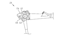
- the endoscope 12 includes an insertion portion 12a to be inserted into the body to be observed, an operation portion 12b provided at the base end portion of the insertion portion 12a, and a curved portion 12c and a tip provided on the tip end side of the insertion portion 12a. It has a part 12d.
- the curved portion 12c bends by operating the angle knob 12e (see FIG. 2) of the operating portion 12b.
- the tip portion 12d is directed in a desired direction by the bending motion of the bending portion 12c.
- the operation unit 12b gives a still image acquisition instruction to the angle knob 12e, a mode changeover switch 12g used for the observation mode switching operation, a zoom operation unit 12h for changing the imaging magnification, and a still image acquisition instruction. It has a still image acquisition instruction unit 12f.
- a console 19 or a foot switch was used in addition to the mode changeover switch 12g or the scope switch of the still image acquisition instruction unit 12f. It may be an operation or an instruction.
- the endoscope system 10 has three modes: a normal observation mode, a special observation mode, and a score display mode.
- a normal observation mode a normal image having a natural color is displayed on the display 18 by illuminating the observation target with normal light and taking an image.
- a special observation mode a special image emphasizing a specific structure is displayed on the display 18 by illuminating the observation target with special light having a wavelength band different from that of normal light and taking an image.
- the score display mode the determined score, the time course of the score, and / Alternatively, the judgment result or the like is displayed on the display.
- the severity of the disease is the degree of prognosis obtained by treatment. For example, when the disease is ulcerative colitis, it is classified into three categories: mild, moderate, and severe. When the disease is ulcerative colitis, the stage of the disease is classified into two stages, an active stage and a remission stage. Therefore, the judgment result of the severity is either mild, moderate, or severe, and the judgment result of the stage is either the active stage or the remission stage, or the remission or non-remission stage.
- the score is a recognizable display of the severity or stage of the disease to be observed, and is a numerical value, a sentence, or the like. In the present embodiment, a case where the image processing device determines remission or non-remission of ulcerative colitis will be described.
- the processor device 16 to which the endoscope 12 is connected is an image processing device that executes a score display mode.
- the image processing device includes a processor.
- programs related to the image signal acquisition unit 51, the DSP 52, the noise reduction unit 53, the signal processing unit 55, the video signal generation unit 56, and the like are incorporated in the memory.
- functions such as an image signal acquisition unit 51, a DSP 52, a noise reduction unit 53, a signal processing unit 55, and a video signal generation unit 56 are realized. ..
- the score display mode may be executed in another configuration.
- an image processing device function is provided in an external image processing system different from the endoscopic system 10, and the endoscopic image is processed by the external image processing.
- the score display mode may be executed by inputting to the device, and the execution result may be displayed on an external display connected to an external image processing system.
- the processor device 16 is electrically connected to the display 18 and the console 19.
- the display 18 outputs and displays an image to be observed, a score, a change over time in the score, a determination result, and / or information incidental to the image to be observed.
- the console 19 functions as a user interface that accepts input operations such as function settings.
- An external recording unit (not shown) for recording an image, image information, or the like may be connected to the processor device 16.
- the light source device 14 emits illumination light to irradiate the observation target. It includes a light source unit 20 and a light source control unit 21 that controls the light source unit 20.
- the light source unit 20 is composed of, for example, a semiconductor light source such as a multi-color LED (Light Emitting Diode), a combination of a laser diode and a phosphor, or a halogen light source such as a xenon lamp.
- the light source unit 20 includes an optical filter or the like for adjusting the wavelength band of light emitted by an LED or the like.
- the light source control unit 21 controls the amount of illumination light by turning on / off each LED and adjusting the drive current and drive voltage of each LED and the like. Further, the light source control unit 21 controls the wavelength band of the illumination light by changing the optical filter or the like.
- the light source unit 20 includes V-LED (Violet Light Emitting Diode) 20a, B-LED (Blue Light Emitting Diode) 20b, and G-LED (Green Light Emitting Diode) 20c.
- R-LED (Red Light Emitting Diode) 20d has four color LEDs.
- the V-LED 20a generates purple light V having a center wavelength of 405 ⁇ 10 nm and a wavelength range of 380 to 420 nm.
- the B-LED 20b generates blue light B having a center wavelength of 460 ⁇ 10 nm and a wavelength range of 420 to 500 nm.
- the G-LED 20c generates green light G having a wavelength range of 480 to 600 nm.
- the R-LED20d generates red light R having a center wavelength of 620 to 630 nm and a wavelength range of 600 to 650 nm.
- the purple light V is a short wavelength light used for detecting a superficial blood vessel dense part, an intramucosal bleeding part, or an extramucosal bleeding part used in the score display mode, and includes 410 nm in the center wavelength or the peak wavelength. Is preferable. Therefore, it is preferable that the endoscopic image used in the score display mode is an image of an observation target illuminated by purple light V.
- the light source control unit 21 controls the V-LED20a, B-LED20b, G-LED20c, and R-LED20d.
- the light source control unit 21 emits normal light having a light intensity ratio of Vc: Bc: Gc: Rc among purple light V, blue light B, green light G, and red light R.
- Vc light intensity ratio of Vc: Bc: Gc: Rc among purple light V, blue light B, green light G, and red light R.
- Each LED 20a to 20d is controlled.
- the light source control unit 21 has a light intensity ratio of Vs: Bs: Gs: of purple light V as short wavelength light and blue light B, green light G, and red light R.
- Each LED 20a to 20d is controlled so as to emit special light that becomes Rs.
- the special light preferably emphasizes surface blood vessels and the like. Therefore, as the light intensity ratio Vs: Bs: Gs: Rs of the special light, it is preferable that the light intensity of the purple light V is larger than the light intensity of the blue light B.
- the ratio of the light intensity Vs of purple light V and the light intensity Bs of blue light B is set to "4: 1".
- the light intensity ratio between the purple light V, the blue light B, the green light G, and the red light R is set to 1: 0: 0: 0, and the light has a short wavelength. May emit only the purple light V as.
- the light intensity ratio includes the case where the ratio of at least one semiconductor light source is 0 (zero). Therefore, this includes the case where any one or more of the semiconductor light sources are not lit. For example, as in the case where the light intensity ratio between purple light V, blue light B, green light G, and red light R is 1: 0: 0: 0, only one of the semiconductor light sources is turned on, and the other three are turned on. Even if one does not light up, it shall have a light intensity ratio.
- the light emitted by each of the LEDs 20a to 20e is incident on the light guide 41 via an optical path coupling portion (not shown) composed of a mirror, a lens, or the like.
- the light guide 41 is built in the endoscope 12 and the universal cord (the cord connecting the endoscope 12, the light source device 14, and the processor device 16).
- the light guide 41 propagates the light from the optical path coupling portion to the tip portion 12d of the endoscope 12.
- the illumination optical system 30a and an imaging optical system 30b are provided at the tip portion 12d of the endoscope 12.
- the illumination optical system 30a has an illumination lens 42, and the illumination light propagated by the light guide 41 is applied to the observation target through the illumination lens 42.
- the image pickup optical system 30b includes an objective lens 43, a zoom lens 44, and an image pickup sensor 45.
- Various types of light such as reflected light, scattered light, and fluorescence from the observation target are incident on the image pickup sensor 45 via the objective lens 43 and the zoom lens 44.
- an image to be observed is formed on the image sensor 45.
- the zoom lens 44 freely moves between the telephoto end and the wide-angle end by operating the zoom operation unit 12h, and enlarges or reduces the observation target to be imaged on the image sensor 45.
- the image pickup sensor 45 is a color image pickup sensor provided with any of R (red), G (green), or B (blue) color filters for each pixel, and images an observation target to image signals of each RGB color. Is output.
- a CCD (Charge Coupled Device) image sensor or a CMOS (Complementary Metal-Oxide Semiconductor) image sensor can be used.
- a complementary color image sensor provided with complementary color filters of C (cyan), M (magenta), Y (yellow) and G (green) may be used. ..
- CMYG four-color image signals are output.
- an RGB image signal similar to that of the image sensor 45 can be obtained by converting the image signals of the four colors of CMYG into the image signals of the three colors of RGB by the complementary color-primary color conversion. Further, instead of the image sensor 45, a monochrome sensor without a color filter may be used.
- the image pickup sensor 45 is driven and controlled by an image pickup control unit (not shown).
- the control by the image pickup control unit is different for each mode.
- the image pickup control unit controls the image pickup sensor 45 so as to take an image of the observation target illuminated by the normal light.
- the Bc image signal is output from the B pixel of the image sensor 45
- the Gc image signal is output from the G pixel
- the Rc image signal is output from the R pixel.
- the image pickup control unit controls the image pickup sensor 45 so as to take an image of the observation target illuminated by the special light.
- the Bs image signal is output from the B pixel of the image sensor 45
- the Gs image signal is output from the G pixel
- the Rs image signal is output from the R pixel.
- the CDS / AGC (Correlated Double Sampling / Automatic Gain Control) circuit 46 performs correlated double sampling (CDS) and automatic gain control (AGC) on the analog image signal obtained from the image sensor 45.
- CDS correlated double sampling
- AGC automatic gain control
- the image signal that has passed through the CDS / AGC circuit 46 is converted into a digital image signal by the A / D (Analog / Digital) converter 48.
- the digital image signal after A / D conversion is input to the processor device 16.
- the processor device 16 includes an image signal acquisition unit 51, a DSP (Digital Signal Processor) 52, a noise reduction unit 53, a memory 54, a signal processing unit 55, and a video signal generation unit 56.
- the signal processing unit 55 includes a normal image generation unit 61, a special image generation unit 62, and a score processing unit 63.
- the image signal acquisition unit 51 acquires a digital image signal of the endoscope image input from the endoscope 12.
- the acquired image signal is transmitted to the DSP 52.
- the DSP 52 performs various signal processing such as defect correction processing, offset processing, gain correction processing, linear matrix processing, gamma conversion processing, demosaic processing, and YC conversion processing on the received image signal.
- defect correction process the signal of the defective pixel of the image sensor 45 is corrected.
- the offset processing the dark current component is removed from the image signal subjected to the defect correction processing, and an accurate zero level is set.
- the gain correction process adjusts the signal level of each image signal by multiplying the image signal of each color after the offset process by a specific gain.
- the image signal of each color after the gain correction processing is subjected to linear matrix processing that enhances color reproducibility. After that, the brightness and saturation of each image signal are adjusted by the gamma conversion process.
- the image signal after the gamma conversion process is subjected to demosaic processing (also referred to as isotropic processing or simultaneous processing), and a signal of the missing color of each pixel is generated by interpolation. By the demosaic process, all the pixels have signals of each color of RGB.
- the DSP 52 performs YC conversion processing on each image signal after demosaic processing, and outputs the luminance signal Y, the color difference signal Cb, and the color difference signal Cr to the noise reduction unit 53.
- the noise reduction unit 53 performs noise reduction processing by, for example, a moving average method, a median filter method, or the like on an image signal that has undergone demosaic processing or the like by DSP 52.
- the image signal with reduced noise is stored in the memory 54.
- the signal processing unit 55 acquires the image signal after noise reduction from the memory 54. Then, the acquired image signal is subjected to signal processing such as color conversion processing, color enhancement processing, and structure enhancement processing as necessary to generate a color endoscopic image in which the observation target is captured.
- the color conversion process is a process of converting an image signal by a 3 ⁇ 3 matrix process, a gradation conversion process, a three-dimensional LUT (look-up table) process, or the like.
- the color enhancement process is performed on the image signal that has undergone the color conversion process.
- the structure enhancement process is a process for emphasizing a specific tissue or structure included in an observation target such as a blood vessel or a pit pattern, and is performed on an image signal after the color enhancement process.
- the signal processing unit 55 includes a normal image generation unit 61, a special image generation unit 62, and a score processing unit 63.
- the signal processing unit 55 sets the transmission destination of the image signal from the noise reduction unit 53 to any one of the normal image generation unit 61, the special image generation unit 62, and the score processing unit 63, depending on the set mode. Specifically, for example, when the normal observation mode is set, the image signal is input to the normal image generation unit 61. When the special observation mode is set, the image signal is input to the special image generation unit 62. When the score display mode is set, the image signal is input to the score processing unit 63.
- the normal image generation unit 61 performs normal image image processing on the input Rc image signal, Gc image signal, and Bc image signal for one frame.
- Image processing for normal images includes 3 ⁇ 3 matrix processing, gradation conversion processing, color conversion processing such as three-dimensional LUT (Look Up Table) processing, color enhancement processing, and structure enhancement processing such as spatial frequency enhancement. Is done.
- the Rc image signal, the Gc image signal, and the Bc image signal that have undergone image processing for a normal image are input to the video signal generation unit 56 as normal images.
- the special image generation unit 62 performs special image image processing on the input Rs image signal, Gs image signal, and Bs image signal for one frame.
- Image processing for special images includes 3 ⁇ 3 matrix processing, gradation conversion processing, color conversion processing such as three-dimensional LUT processing, color enhancement processing, and structure enhancement processing such as spatial frequency enhancement.
- the Rs image signal, the Gs image signal, and the Bs image signal that have undergone image processing for special images are input to the video signal generation unit 56 as special images.
- the endoscopic image generated by the signal processing unit 55 is a normal observation image when the observation mode is the normal observation mode, and is a special observation image when the observation mode is the special observation mode. Therefore, color conversion processing and color enhancement are performed.
- the contents of the process and the structure enhancement process differ depending on the observation mode.
- the signal processing unit 55 In the normal observation mode, the signal processing unit 55 generates the normal observation image by performing the various signal processings described above so that the observation target has a natural hue.
- the signal processing unit 55 In the special observation mode, the signal processing unit 55 generates a special observation image by performing at least the various signal processings that emphasize the blood vessels to be observed.
- blood vessels in the special observation image generated by the signal processing unit 55, blood vessels (so-called superficial blood vessels) or blood located at a relatively shallow position in the observation target with respect to the surface of the mucous membrane have a magenta color (for example, brown color). Blood vessels located relatively deep in the observation target with respect to the surface of the mucosa (so-called middle-deep blood vessels) have a cyan-based color (for example, green). Therefore, the blood vessels or bleeding (blood) to be observed are emphasized by the difference in color with respect to the mucous membrane represented by the pinkish color.
- magenta color for example, brown color
- middle-deep blood vessels have a cyan-based color (for example, green). Therefore, the blood vessels or bleeding (blood) to be observed are emphasized by the difference in color with respect to the mucous membrane represented by the pinkish color.
- the video signal generation unit 56 converts a normal image, a special image, a final score determined by the score processing unit 63, etc. output from the signal processing unit 55 into a video signal that can be displayed in full color on the display 18.
- the converted video signal is input to the display 18.
- a normal image, a special image, a final score, or the like is displayed on the display 18.
- the signal processing unit 55 stores the generated endoscopic image in the image storage unit 75 (see FIG. 8) or storage. Save in (not shown).
- the storage is an external storage device connected to the processor device 16 such as a LAN (Local Area Network), and is, for example, a file server of a system for filing an endoscopic image such as a PACS (Picture Archiving and Communication System, see FIG. 21). , NAS (Network Attached Storage), etc.
- LAN Local Area Network
- PACS Picture Archiving and Communication System
- NAS Network Attached Storage
- the score processing unit 63 determines the final score and controls to display the final score and / or the time-dependent change of the final score on the display 18 in real time. As shown in FIG. 8, the score processing unit 63 includes an image acquisition unit 71, a raw score calculation unit 72, a final score determination unit 73, and a display control unit 76. Further, an unsuitable image discrimination unit 74, an image storage unit 75, and a site determination unit 77 may be provided.
- the image acquisition unit 71 automatically acquires a plurality of endoscope images obtained by imaging observation targets with the endoscope 12 at different times.
- the image acquisition unit 71 acquires a special observation image in which blood vessels and the like are emphasized.
- the image acquisition unit 71 may acquire an endoscopic image from the storage as the case may be.
- the endoscopic image acquired by the image acquisition unit 71 is sent to the raw score calculation unit 72, the inappropriate image discrimination unit 74, or the image storage unit 75.
- the elementary score calculation unit 72 calculates the elementary score related to the determination of the severity or stage of the disease to be observed based on the plurality of endoscopic images acquired by the image acquisition unit 71.
- the elementary score related to the determination of the severity or stage of the disease to be observed shall be a numerical value recognizable as to the severity or stage of the disease to be observed included in the endoscopic image.
- the raw score calculation unit 72 can include one or both of the first calculation unit 81 (see FIG. 8) and the second calculation unit 82 (see FIG. 8).
- the elementary score calculation unit 72 calculates the elementary score based on the feature amount (first feature amount) obtained by analyzing the endoscopic image in the first calculation unit 81.
- the characteristic amounts include, for example, the number of blood vessels, thickness, length, number of branches, branch angle, distance between branch points, number of intersections, inclination, density, color, blood concentration, oxygen saturation, presence / absence of bleeding, and bleeding. Examples include a characteristic amount related to blood vessels such as area or flow rate, or a characteristic amount related to mucosal color.
- the amount related to the superficial blood vessel dense part, the intramucosal bleeding part, and the extramucosal bleeding part included in the endoscopic image is preferably mentioned.
- the surface layer blood vessel dense part the blood vessel to be observed is extracted from the endoscopic image by an image analysis of the endoscopic image with a frequency filter or the like, and the number of pixels of the part where the blood vessel is dense in the endoscopic image is determined. The counted value is used as the raw score.
- the intramucosal or extramucosal bleeding part the intramucosal or extramucosal bleeding to be observed is extracted from the endoscopic image by the value of G value with respect to the R value proportional to the amount of hemoglobin, and the endoscopic image.
- the value obtained by counting the number of pixels in the intramucosal or extramucosal bleeding portion in the above is taken as the raw score.
- the ulcerative colitis which is a disease determined by the present embodiment, has the present invention in which the pattern of vascular structure changes as the severity worsens. Is finding out.
- the pattern of superficial blood vessels 85 is regular (FIG. 9 (A)), or the pattern of superficial blood vessels 85 is regular. There is some turbulence in the large intestine (Fig. 9 (B)).
- the raw score calculation unit 72 can calculate the raw score by utilizing the above-mentioned pattern change of the blood vessel structure.
- the surface blood vessel dense portion refers to a state in which the surface blood vessels meander and gather, and in the appearance on the image, a number of surface blood vessels surround the intestinal gland bulk (crypt) (see FIG. 10).
- Intramucosal bleeding refers to intramucosal bleeding (see FIG. 10) that requires differentiation from luminal bleeding.
- Intramucosal bleeding refers to bleeding that is not in the mucosa and in the lumen (lumen, pleated hole) in appearance on the image.
- Extramucosal bleeding is accompanied by a small amount of blood into the lumen, blood that oozes out of the lumen in front of the endoscope or is visible after cleaning the lumen, or bleeding on the hemorrhagic mucosa. It refers to the blood in the lumen.
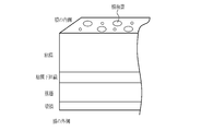
- the elementary score calculation unit 72 classifies the superficial blood vessel dense part, the intramucosal bleeding part, or the extramucosal bleeding part according to the frequency characteristic and the brightness value obtained from the special observation image. Specifically, the superficial blood vessel dense part, the intramucosal bleeding part, or the extramucosal bleeding part is classified as shown in FIG.
- the density of superficial blood vessels is represented by a low luminance value and a high frequency characteristic.
- Intramucosal hemorrhage is represented by a medium brightness value and a medium frequency characteristic.
- Extramucosal hemorrhage is represented by a low luminance value and a low frequency characteristic.
- the blurred dark part of the special observation image or Endoscopic shadows are also included.
- superficial vascular congestion, intramucosal bleeding, and extramucosal bleeding necessary for determining remission or non-remission of ulcerative colitis from superficial vascular congestion, intramucosal bleeding, or extramucosal bleeding Is extracted.
- the spatial frequency component distribution is calculated by applying a Laplacian filter to the special observation image. Based on the spatial frequency component distribution, for example, when the standard deviation of the frequencies of nine nearby pixels including the specific pixel is equal to or less than a certain value, the specific pixel is defined as a pixel belonging to the low frequency region.
- the high frequency region is extracted by Hesian analysis for the spatial frequency component distribution.
- the portion of the special observation image excluding the low frequency region and the high frequency region is defined as the medium frequency region. In this way, by classifying the pixels of the special observation image according to the spatial frequency and the brightness value, the number of pixels of the superficial blood vessel dense part, the intramucosal bleeding part, or the extramucosal bleeding part can be calculated.
- the disease is ulcerative colitis because the severity or stage of the disease can be satisfactorily determined by the above configuration.
- the raw score calculated based on the different first feature amount is a different kind of raw score.
- the raw score calculation unit 72 may calculate one kind of raw score or two or more kinds of raw scores.
- the raw score calculation unit 72 calculates the raw score based on the endoscopic image in the second calculation unit 82.
- the second calculation unit 82 includes a trained first machine learning model.
- the trained first machine learning model is generated by inputting a past endoscopic image associated with a raw score into the machine learning model. That is, it is a machine learning model generated by inputting a past endoscopic image into a machine learning model and learning so that the associated elementary score is output correctly. Therefore, “learned” includes adjusting various parameters in addition to inputting the past endoscopic image associated with the score into the machine learning model.
- the elemental score associated with the past endoscopic image may be, for example, a feature amount, or may be a numerical value of the severity or stage of the disease to be observed.
- the first machine learning model may include two or more types of machine learning models corresponding to each feature amount, and may calculate two or more types of elementary scores.
- the final score determination unit 73 determines the final score based on the raw score.
- the raw score calculated by the raw score calculation unit 72 is an amount related to the determination of the severity or stage of the disease, and is an index of how much the disease is a symptom or how far the stage of the disease is advanced. Is. Therefore, the method of determining the final score may be adjusted according to the purpose of the determination and the like. For example, when determining the degree of severity or the progress of a stage, the final score is set in the direction in which the raw score value is large, the severity is high, and the stage is advanced, and the disease worsens most. Determine the severity or stage of the affected area.
- the final score is determined by setting a threshold value in advance for each of the three types of elementary scores, for example, the number of pixels in the superficial blood vessel dense area, the number of pixels in the intramucosal bleeding area, and the number of pixels in the extramucosal bleeding area.
- the method of determining the score and the like can be mentioned.
- the threshold value is set low.
- the display control unit 76 controls to display the final score and / or the time-dependent change of the final score on the display 18 in real time.
- the final score is, for example, a graph in which the numerical value of the final score is displayed on the display 18 in real time, the vertical axis is the final score value, and the horizontal axis is the passage of time.
- a method of displaying the score as a change over time in a graph format, or displaying a message notifying the severity of the disease or the judgment result of the stage by the value of the final score and the preset threshold value can be mentioned.
- the display control unit 76 also controls not to display the final score or the like. For example, if the final score is smaller than the preset threshold, the final score is not displayed. Note that displaying in real time means displaying immediately, and does not mean displaying at exactly the same time.
- the score processing unit 63 configured as described above determines the final score using the raw score and then displays it on the display 18, the change in the raw score is not displayed as it is on the display 18, and the raw score is not displayed as it is.
- the score is controlled not to display the final score, so when the score is displayed, it is displayed as a more stable score.
- the image processing apparatus does not cause the final score to fluctuate even if the observation target changes finely, and more stable and robust score calculation and display of the final score and the like are performed. Therefore, the image processing device contributes to the prevention of oversight of the lesion of the user who performs the observation or the simpler observation.
- the score processing unit 63 may include an unsuitable image discrimination unit 74.
- the unsuitable image discrimination unit 74 determines whether the endoscopic image is appropriate or unsuitable for the calculation of the raw score. By discrimination, the endoscopic image is either appropriate or inappropriate.
- the endoscopic image may be unsuitable as an image for calculating the raw score. For example, in the endoscopic image, there were many blurred parts because the tip 12d of the endoscope was photographed while moving, causing blurring, water droplets adhering to the image, and the observation target was slanted. Or, an extreme value may be calculated when the raw score is calculated because only the distant view is photographed and the observation target is hardly included. Such endoscopic images, for which an inappropriate score may be calculated, are unsuitable for the calculation of the raw score.
- the score processing unit 63 can include one or both of the first determination unit 83 (see FIG. 8) and the second determination unit 84 (see FIG. 8).
- the first discrimination unit 83 determines whether the endoscopic image is appropriate or unsuitable for the calculation of the raw score based on the feature amount (second feature amount) obtained by analyzing the endoscopic image.
- the feature amount is at least one selected from the halation distribution, the spatial frequency distribution, the brightness value distribution, the shadow distribution, the magnification index, and the reflected light distribution of the illumination light irradiating the observation target. It is preferably a related amount.
- the area where halation occurs or the area of shadow due to the hood of the endoscope is an extremely bright or dark area. Therefore, an endoscopic image having many of these areas is calculated as a raw score. It is not suitable for. An endoscopic image with many extremely bright or dark areas due to the brightness value distribution or the shadow distribution is also unsuitable for calculating the raw score. An endoscopic image in which the image is often blurred due to the spatial frequency distribution is unsuitable for calculating the raw score because it is an image in which blurring occurs or the image is out of focus.
- the enlargement ratio is large with reference to the enlargement ratio index, for example, when the surface layer blood vessel dense part is calculated, the appearance of blood vessels changes and the blood vessel density per unit area also changes as compared with the case where no enlargement occurs. do. Therefore, it is good to calculate the raw score in consideration of the enlargement ratio, but otherwise it is not suitable for calculating the raw score.
- the observation target is changed to a different type due to a change in the observation site or the like, the reflected light distribution of the illumination light irradiating the observation target may change. An endoscopic image in which there are many extremely bright or dark areas due to changes in the reflected light distribution is also unsuitable for calculating the raw score.
- the value calculated based on the different second feature amount shall be a different type of second feature amount.
- the first discrimination unit 83 may calculate one type of the second feature amount, or may calculate two or more types.
- the first discriminating unit 83 discriminates whether the endoscopic image is appropriate or unsuitable for the calculation of the raw score by using one kind or two or more kinds of second feature quantities.
- the unsuitable image discriminating unit 74 determines in the second discriminating unit 84 whether it is appropriate or unsuitable for the calculation of the raw score based on the endoscopic image.
- the second discriminating unit 84 includes a trained second machine learning model.
- the trained second machine learning model is generated by inputting a past endoscopic image associated with the calculation of the raw score into the machine learning model. That is, it is an opportunity learning model generated by inputting a past endoscopic image into an opportunity learning model so as to correctly output whether it is appropriate or inappropriate for the calculation of a raw score. Therefore, “learned” includes the adjustment of various parameters in addition to inputting the past endoscopic images associated with the calculation of the raw score into the machine learning model. ..
- the endoscopic image determined to be appropriate for the calculation of the raw score by the unsuitable image discrimination unit 74 is sent to the raw score calculation unit 72 to calculate the raw score.
- An endoscopic image that is determined to be unsuitable for the calculation of the raw score is regarded as "not calculated” as the raw score. That is, since the raw score is labeled as "not calculated", it is distinguished from the endoscopic image for which the raw score has not been calculated yet.
- the final score determination unit 73 determines the final score from the raw scores calculated based on a plurality of endoscopic images acquired in a predetermined period before the time of the final score determination.
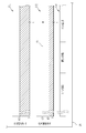
- the determination of the final score in this case will be specifically described with reference to FIG.
- FIG. 12 the flow from the start of observation by the endoscope is shown in the upper part, and the appearance of the obtained endoscopic image is shown in the lower part.
- Observation with an endoscope is started, and endoscopic image acquisition 101 starts from S at the start of observation.
- the image signal acquisition unit 51 automatically performs endoscopic image acquisition 101 at a predetermined image acquisition interval a. As soon as the endoscopic image acquisition 101 is performed, the raw score of the endoscopic image is calculated.
- the endoscopic image acquisition 101 is indicated by a filled circle, but only a part thereof is coded in order to avoid complicating the figure. Further, also for the period a, only a part of the period a is coded in order to avoid complicating the figure.
- the final score is determined based on the endoscopic image acquired in the period ⁇ t before the final score determination time t, which is the determination time of the final score.
- the period ⁇ t is a predetermined period and is set in advance.
- the first endoscopic image acquired during the period ⁇ t is the endoscopic image 121 acquired at the time t ⁇ t.
- the endoscopic image 121 included an intramucosal hemorrhagic site 126 and a vascularized area 127.
- the intramucosal hemorrhagic portion 126 and the blood vessel dense portion 127 are shown by diagonally shaded portions and shaded portions, respectively, but only a part thereof is indicated in order to avoid complicating the drawings.
- the unsuitable image discriminating unit 74 determines whether it is appropriate or unsuitable for the calculation of the raw score using the period B, and is unsuitable.
- the discrimination result is obtained at the time of the image discrimination 102.
- the discrimination result was "appropriate".
- the raw score calculation unit 72 calculated the raw score in the endoscopic image 121 using the period C, and obtained the calculation result at the time of the raw score calculation 103.
- the elementary score calculation unit is the first calculation unit 81 for two types, the number of pixels of the intramucosal and extramucosal bleeding part (hereinafter referred to as the number of bleeding part pixels) and the number of blood vessel dense part pixels (hereinafter referred to as the number of dense part pixels).
- the raw score was calculated by.
- the calculation results were "the number of pixels in the bleeding part: 100" and "the number of pixels in the dense part: 70".
- the second primary score is calculated for the endoscopic image 122 acquired at time t ⁇ t + 4a.
- the endoscopic image 122 included an intramucosal bleeding section 126, a vascular dense section 127, and an extramucosal bleeding section 128.
- the extramucosal bleeding portion 128 is indicated by a filled circle, but only a part thereof is designated in order to avoid complicating the figure.
- the unsuitable image discriminating unit 74 determines whether it is appropriate or unsuitable for the calculation of the raw score using the period B, and is unsuitable.
- the discrimination result is obtained at the time of image discrimination 104.
- the discrimination result was "appropriate".
- the raw score calculation unit 72 calculated the raw score in the endoscopic image 122 using the period C, and obtained the calculation result at the time of the raw score calculation 105.
- the raw score calculation unit calculated the raw score by the first calculation unit 81 for two types, the number of pixels in the bleeding part and the number of pixels in the dense part. The calculation results were "the number of pixels in the bleeding part: 120" and "the number of pixels in the dense part: 90".
- the third element score is calculated for the endoscopic image 123 acquired at time t ⁇ t + 8a. Since the endoscope image 123 was acquired while the endoscope was moving, it was an unclear image 129 in which the observation target was blurred, and the observation target could not be identified. With respect to the endoscopic image 123 obtained by the endoscopic image acquisition 101 at time t ⁇ t + 8a, the unsuitable image discriminating unit 74 determines whether it is appropriate or unsuitable for the calculation of the raw score using the period B, and is unsuitable. The discrimination result is obtained at the time of image discrimination 106. The discrimination result was "inappropriate".
- the raw score calculation unit 72 does not calculate the raw score because the result of the unsuitable image discrimination is "inappropriate". That is, the calculation result of the raw score was "not calculated".
- the fourth element score is calculated for the endoscopic image 124 acquired at time t ⁇ t + 12a.
- the endoscopic image 124 included an intramucosal bleeding section 126, a blood vessel congested section 127, and an extramucosal bleeding section 128.
- the unsuitable image discriminating unit 74 determines whether it is appropriate or unsuitable for the calculation of the raw score using the period B, and is unsuitable.
- the discrimination result is obtained at the time of image discrimination 108.
- the discrimination result was "appropriate".
- the raw score calculation unit 72 calculated the raw score in the endoscopic image 124 using the period C, and obtained the calculation result at the time of the raw score calculation 109.
- the raw score calculation unit calculated the raw score by the first calculation unit 81 for two types, the number of pixels in the bleeding part and the number of pixels in the dense part. The calculation results were "the number of pixels in the bleeding part: 140" and "the number of pixels in the dense part: 140".
- the endoscopic image acquired in the period ⁇ t is related to the image acquisition interval a, the period of inappropriate image discrimination by the inappropriate image discrimination unit 74, and the period of raw score calculation by the raw score calculation unit 72.
- Endoscopic images 121, 122, 123, and 124 it is preferable that the final score determination unit 73 determines the final score based on the raw scores other than "uncalculated" among these endoscopic images. Therefore, the final score determination unit 73 determines the final score from the respective raw scores calculated based on the three endoscopic images 121, 122, and 124.
- the final score determination unit 73 determines the final score by moving average, FIR (finite impulse response) filtering, or IIR (Infinite impulse response) filtering of a plurality of raw scores.
- the moving average is preferably any of a simple moving average, a weighted moving average, an exponential moving average, or a triangular moving average.
- weighting is used in the moving average, a value determined in advance so as to obtain a preferable result can be set and used depending on the observation site, the difference in the conditions for acquiring the endoscopic image, and the like.
- the final score can be determined in a plurality of raw scores with less influence of noise such as raw scores of extremely distant values. Therefore, the final score is stably determined.
- the final score determination time t for example, when the final score is obtained by a simple moving average of the raw scores and the raw score is the number of pixels of the bleeding part, the number of pixels of the bleeding parts in the endoscopic images 121, 122, and 124 is averaged. do. That is, the first type of final score is the number of bleeding part pixels 100 of the endoscopic image 121, the number of bleeding part pixels 120 of the endoscopic image 122, and the endoscopic image as shown in the following formula (1). The number of pixels of the bleeding portion 140 of 124 is averaged to 120.
- the second type of final score is as follows, as shown in the following formula (2), the number of pixels of the bleeding part of the endoscope image 121 is 100, the number of pixels of the bleeding part of the endoscope image 122 is 120, and the endoscope. The number of pixels of the bleeding portion 140 in the image 124 is averaged to 100.
- the interval for determining the final score may be automatically determined, or the final score at the instructed time may be determined by instruction.
- the instruction for example, the time when the user acquires the still image by the still image acquisition instruction unit 12f (freeze button) may be set as the final score determination time t. Therefore, in this case, the display control unit 76 controls to display the change with time of the final score and / or the final score when the still image acquisition instruction unit 12f gives a still image acquisition instruction.
- the observation target for which the user saves a still image often includes a region of interest. It is preferable to determine the final score in such an area and display it on the display 18 because it contributes to a more appropriate diagnosis of the user.
- the display control unit 76 controls to display the final score and / or the time-dependent change of the final score on the display 18 in real time.
- a display control method a method capable of stably displaying the determination result of the final score is preferable. Therefore, for example, the display control unit 76 displays the final score having the largest numerical value among the final scores from the start of observation, and updates the display of the final score when a final score larger than the previous numerical values is obtained. Examples thereof include a method and a method of displaying the change over time of the final score.
- the change over time of the final score it is preferable to display it as a graph.
- the graph is preferably displayed by at least one graph showing the relationship between the final score and the final score determination time.
- the display control unit 76 controls whether or not to display the final score according to the threshold value at the final score determination time t described above.
- the threshold value T1 for the number of pixels in the bleeding part was set to 800
- the threshold value T2 for the number of pixels in the dense part was set to 40. Since the final score of the number of bleeding part pixels at the final score determination time t was 120, it is smaller than the threshold value T1 of 800. Therefore, the number of bleeding part pixels at the final score determination time t is not plotted on the graph 131 of the number of bleeding part pixels which is the final score.
- the graph 132 of the number of dense part pixels, which is the final score is plotted with an auxiliary line 133 attached so that the numerical value can be grasped at a glance by the number of dense part pixels at the final score determination time t.
- the threshold value T1 or the threshold value T2 is indicated by diagonal lines.
- the display control unit 76 By controlling the display control unit 76 to display the final score and / or the time-dependent change of the final score on the display 18 in real time, the user can worsen the disease even while observing the observation target. You can see at a glance what the item you think is. also. By showing the change over time in a graph, it is possible to grasp the approximate position of the part that seems to be the worst. Further, by controlling the display of the final score by the threshold value, only the item in which the disease is considered to be the most aggravated is displayed, so that the display of the final score can be made more stable.
- the graph displayed on the display 18 may be limited to one or the like. Specifically, for example, when one of the two types of final scores is equal to or higher than the threshold value and the other is less than the threshold value, only the graph of the final score which is equal to or higher than the threshold value is displayed. By carefully selecting and displaying the types of parameters such as the final score, the reliability or stability of the displayed final score is improved. In addition, the user can grasp information for diagnosing the severity or stage at a glance.
- a part determination unit 77 for determining the part to be observed included in the endoscopic image by image analysis of the endoscopic image is provided, and the change with time of the final score can be checked with the final score and the final score. It may be displayed by a graph showing the relationship between the determination time and the part. As a result, the endoscopic image is automatically analyzed, and the part name is displayed corresponding to the display of the change with time of the final score.
- FIG. 14 for example, in observing the large intestine, when screening while pulling the endoscope from the part of the cecum at the back of the large intestine, "cecum, ascending colon, transverse colon, descending colon, sigmoid colon, A site name 134 such as "rectum” is displayed. By displaying the site name 134 in this way, it is possible to grasp the part where the disease is exacerbated in the observation without omission, which is preferable.
- the final score determination unit 73 may determine the final score based on the raw score calculated immediately before or after the time of the final score determination. The determination of the final score in these cases will be specifically described with reference to FIGS. 15 and 16. As shown in FIG. 15, in the method of determining the final score based on the raw score calculated immediately before the time of determining the final score, the final score is determined instead of using a plurality of raw scores. The decision is made based on the raw score calculated immediately before the time of the decision. That is, the raw score calculated immediately before the time when the final score is determined is determined as the final score. The endoscopic image acquisition and the raw score acquisition are the same as described above.
- the raw score calculated immediately before the final score determination time t is calculated at the time of the raw score calculation 109 based on the endoscopic image acquired by the endoscopic image acquisition at the time t ⁇ t + 12a, “bleeding portion”. Since the number of pixels is 140 and the number of pixels in the dense area is 140, the final score is the number of pixels in the bleeding area: 140 and the number of pixels in the dense area: 140.
- the display of the final score using the threshold value by the display control unit 76 is the same as described above. Therefore, as shown in FIG. 15, the display 18 displays a graph 132 of the number of dense part pixels in which the number of dense part pixels is plotted at 140 as the final score.
- the final score is determined.
- the final score is determined based on the raw score calculated immediately after the final score determination time t. That is, the raw score calculated immediately after the final score determination time t is determined as the final score.
- This is a raw score calculated for the endoscopic image acquired at the final score determination time t.
- the endoscopic image acquisition and the raw score acquisition are the same as described above.
- the raw score calculated immediately after the final score determination time t is calculated at the time of the raw score calculation 111 based on the endoscopic image acquired by the endoscopic image acquisition at the time t, "Number of bleeding part pixels”. : 160 ”and“ the number of pixels in the dense area: 70 ”, so the final score is“ the number of pixels in the bleeding area: 160, the number of pixels in the dense area: 70 ”.
- the display of the final score using the threshold value by the display control unit 76 is the same as described above. Therefore, as shown in FIG. 16, the display 18 displays a graph 132 of the number of dense part pixels in which the number of dense part pixels is plotted at 70 as the final score.
- the method of determining the final score based on the raw score calculated immediately before or immediately after the final score determination is suitable when it is desired to grasp the final score of the observation target currently being observed. Moreover, it is preferable because the latest final score can be displayed in a stable manner.
- the final score is determined based on the raw score calculated immediately before or after the time when the final score is determined.
- the final score based on the observation site for which the still image acquisition instruction is given which is the area that the user wants to pay attention to, can be displayed quickly and stably. Therefore, the final score is displayed at the timing when the user wants to obtain information on the diagnosis, which is preferable because it responds to the user's needs.
- the final score determination unit 73 includes the number of raw scores that were not calculated by the inappropriate image discrimination unit 74 among the raw scores based on the plurality of endoscopic images acquired during the predetermined period, and the calculated raw scores. You may decide whether to calculate or not to calculate the final score from the number of. Specifically, among the raw scores based on a plurality of endoscopic images acquired in a predetermined period, when the number of raw scores other than uncalculated is less than or equal to the predetermined number, the number of uncalculated raw scores is the predetermined number. In the above cases, or when the ratio of the number of uncalculated raw scores to the number of raw scores based on multiple endoscopic images acquired in a predetermined period is equal to or greater than the predetermined value, the final score is "not calculated". And.
- the endoscopic image acquisition 101 is automatically performed at the image acquisition interval a, and the time t ⁇ t, the time t ⁇ t + 4a, the time t ⁇ t + 8a, and the time t.
- An endoscopic image is acquired at ⁇ t + 12a.
- the unsuitable image discrimination unit 74 determines whether the endoscopic image acquired at each time after the period B is appropriate or unsuitable for the calculation of the raw score.
- the endoscopic images 122 and 123 acquired at the time t- ⁇ t + 4a and the time t- ⁇ t + 8a were unclear images 129, so that the raw score calculation unit 72 is the endoscopic image.
- the raw score was set to "not calculated" for each of 122 and 123.
- the final score when the number of elementary scores other than uncalculated is 2 or less among the elementary scores based on a plurality of endoscopic images acquired in a predetermined period, the final score is defined as "uncalculated”. Therefore, in this case, since there are four plurality of endoscopic images, two uncalculated raw scores, and two non-calculated raw scores, "a raw score other than uncalculated raw score". When the number of is 2 or less ”corresponds. Therefore, the final score at the final score determination time t is set to "not calculated”.
- the display control unit 76 controls not to display the uncalculated final score on the display. Therefore, as shown in FIG. 18, the display 18 does not plot the final score on either graph 131 or graph 132.
- the predetermined value is 0.5
- the number of endoscopic images and raw scores acquired during the period ⁇ t is 4, and the number of raw scores that are “uncalculated” is 2. Since the above ratio is 2/4 (0.5), the final score is set to "not calculated".
- the unsuitable image discrimination unit 74 it is not preferable to determine whether to calculate the final score or not from the number of raw scores calculated by the unsuitable image discrimination unit 74 and the number of calculated raw scores. It is preferable because the number or ratio of the raw scores is suppressed, the final score is appropriately determined, and the display of the score is stable.
- the final score may be displayed by a message notifying the severity of the disease to be observed or the judgment result of the stage.
- the severity or stage is determined by the final score.
- the display control unit 76 uses a threshold value for controlling whether or not to display the final score. That is, in the final score, the severity or the stage is determined by the threshold value T1 of the number of pixels of the bleeding part and the threshold value T2 of the number of pixels of the dense part.
- the severity when the number of bleeding part pixels is the threshold value T1 or more, it is severe, when the number of bleeding part pixels is less than the threshold value T1 and the number of dense part pixels is the threshold value T2 or more, it is moderate, or the number of bleeding part pixels is less than the threshold value.
- the case where the number of pixels in the dense area is less than the threshold value T2 is regarded as mild.
- pathological non-remission or bleeding is caused by severe illness when the number of bleeding part pixels is the threshold T1 or more and moderate illness when the number of bleeding part pixels is less than the threshold T1 and the number of dense part pixels is the threshold T2 or more.
- a mild case in which the number of pixels is less than the threshold value and the number of pixels in the dense area is less than the threshold value T2 is defined as pathological remission.
- the message notifying the determination result of the severity or the stage is performed by displaying the message 135 on a part of the display 18, for example.
- message 135 is either "severe”, “moderate”, or “mild” in the case of severity, or "remission” or “non-remission” in the case of stage. That message.
- the user can obtain information to support the diagnosis of the severity or stage at a glance without disturbing the observation. preferable.
- the endoscope 12 obtains an endoscope image which is a special image at a certain point in time by imaging an observation target illuminated by special light (step ST110).
- the final score is set to be automatically acquired at predetermined intervals.
- the image acquisition unit 71 acquires a special image from the endoscope 12 (step ST120).
- the special image is sent to the unsuitable image discriminating unit 74, and it is discriminated whether it is appropriate or unsuitable for calculating the raw score.
- the raw score is calculated based on the special image (step ST140).
- the raw score is set to "uncalculated" (step ST150).
- the final score is determined from the calculation result of the raw score (step ST160).
- the display control unit 76 controls the display of the final score (step ST170).
- the display displays the final score with a controlled display (step ST180).
- the observation is finished (YES in step ST190)
- the observation is finished. If the observation is not completed (NO in step ST190), the process returns to the endoscopic image acquisition.
- the present invention is applied to an endoscopic system that processes an endoscopic image, but it is applied to a medical image processing system that processes a medical image other than the endoscopic image.
- the medical image processing system includes the image processing apparatus of the present invention.
- the present invention can also be applied to a diagnostic support device for providing diagnostic support to a user using a medical image.
- the present invention can also be applied to a medical work support device for supporting medical work such as a diagnostic report by using a medical image.
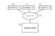
- the diagnostic support device 201 is used in combination with a modality such as a medical image processing system 202 and a PACS (Picture Archiving and Communication Systems) 203.
- the medical service support device 210 includes various inspection devices such as the first medical image processing system 211, the second medical image processing system 212, ..., The Nth medical image processing system 213, and an arbitrary network. Connect via 214.
- the medical service support device 210 receives medical images from the first to Nth medical image processing systems 211, 212, ..., 213, and supports the medical service based on the received medical images.
- hardware of a processing unit that executes various processes such as an image signal acquisition unit 51, a DSP 52, a noise reduction unit 53, a signal processing unit 55, and a video signal generation unit 56 included in the processor device 16.
- the hardware-like structure is various processors as shown below.
- the circuit configuration is changed after manufacturing the CPU (Central Processing Unit), FPGA (Field Programmable Gate Array), etc., which are general-purpose processors that execute software (programs) and function as various processing units. It includes a programmable logic device (PLD), which is a possible processor, a dedicated electric circuit, which is a processor having a circuit configuration specially designed for executing various processes, and the like.
- PLD programmable logic device
- One processing unit may be composed of one of these various processors, or may be composed of a combination of two or more processors of the same type or different types (for example, a plurality of FPGAs or a combination of a CPU and an FPGA). May be done. Further, a plurality of processing units may be configured by one processor. As an example of configuring a plurality of processing units with one processor, first, as represented by a computer such as a client or a server, one processor is configured by a combination of one or more CPUs and software. There is a form in which this processor functions as a plurality of processing units.
- SoC System On Chip
- a processor that realizes the functions of the entire system including a plurality of processing units with one IC (Integrated Circuit) chip is used.
- the various processing units are configured by using one or more of the above-mentioned various processors as a hardware-like structure.
- the present invention can also be implemented by the following alternative embodiments.
- a plurality of endoscopic images obtained by imaging observation objects at different times with an endoscopic device are acquired, and the observation objects are acquired. Based on each endoscopic image, a raw score associated with determining the severity or stage of the disease to be observed is calculated. Determine the final score based on the raw score, A processor device that controls the display of the final score and / or the change over time of the final score in real time.
Landscapes
- Health & Medical Sciences (AREA)
- Engineering & Computer Science (AREA)
- Medical Informatics (AREA)
- Life Sciences & Earth Sciences (AREA)
- Public Health (AREA)
- General Health & Medical Sciences (AREA)
- Biomedical Technology (AREA)
- Surgery (AREA)
- Nuclear Medicine, Radiotherapy & Molecular Imaging (AREA)
- Radiology & Medical Imaging (AREA)
- Pathology (AREA)
- Physics & Mathematics (AREA)
- Optics & Photonics (AREA)
- Veterinary Medicine (AREA)
- Biophysics (AREA)
- Heart & Thoracic Surgery (AREA)
- Molecular Biology (AREA)
- Animal Behavior & Ethology (AREA)
- Primary Health Care (AREA)
- Epidemiology (AREA)
- Data Mining & Analysis (AREA)
- Signal Processing (AREA)
- Databases & Information Systems (AREA)
- General Physics & Mathematics (AREA)
- Quality & Reliability (AREA)
- Computer Vision & Pattern Recognition (AREA)
- Theoretical Computer Science (AREA)
- Artificial Intelligence (AREA)
- Evolutionary Computation (AREA)
- Business, Economics & Management (AREA)
- General Business, Economics & Management (AREA)
- Endoscopes (AREA)
- Image Processing (AREA)
Abstract
内視鏡画像を用いて疾患に関する判定結果を安定して表示する画像処理装置、内視鏡システム、及び画像処理方法を提供する。 プロセッサを備える画像処理装置16であって、プロセッサは、内視鏡12によって観察対象を撮像して得る複数の内視鏡画像を取得し、それぞれの内視鏡画像に基づいて、観察対象の疾患の重症度またはステージの判定に関連する素スコアを算出し、素スコアに基づいて最終スコアを決定し、最終スコア及び/又は最終スコアの経時変化をリアルタイムでディスプレイ18に表示する制御を行う。
Description
本発明は、内視鏡で撮影した内視鏡画像を用いて診断支援を行う画像処理装置、内視鏡システム、及び画像処理方法に関する。
医療分野においては、光源装置、内視鏡、及びプロセッサ装置を備える内視鏡システムを用いた診断が広く行われている。内視鏡システムを用いた診断では、内視鏡で観察対象を撮影して得た画像(以下、内視鏡画像という)に適切な画像処理を施すことにより、観察対象の特定の疾患のステージ等を判定する、CAD(Computer-Aided Diagnosis、コンピュータ支援診断)の技術が開発されている。CADを用いることにより、リアルタイム、または準リアルタイムに、例えば、疾患の重症度、または病理結果に紐づくスコア等が算出され、ディスプレイ等に表示される。
CADをより簡便に使用するための技術が開示されている。例えば、内視鏡画像における超拡大画像を用いるCADのために、超拡大画像と非拡大画像とを自動判別可能とした画像解析装置が知られている(特許文献1)。
内視鏡画像を用いたリアルタイムでのCADにおいては、内視鏡画像における観察対象の位置が変化しやすいために、安定した判定結果が得られない場合がある。例えば、内視鏡画像の画像処理によって、潰瘍性大腸炎のステージ判定を行う場合には、観察位置が細かく変化すると判定結果も細かく変化するため、ステージ判定の結果が安定しない場合がある。したがって、より利用しやすいCADとするために、安定した判定結果が得られることが望まれている。
本発明は、上記実情に鑑み、内視鏡画像を用いて疾患に関する判定結果を安定して表示する画像処理装置、内視鏡システム、及び画像処理方法を提供することを目的とする。
本発明は、画像処理装置であって、プロセッサを備える。プロセッサは、内視鏡によって観察対象を互いに異なる時刻に撮像して得る複数の内視鏡画像を取得し、それぞれの内視鏡画像に基づいて、観察対象の疾患の重症度またはステージの判定に関連する素スコアを算出し、素スコアに基づいて最終スコアを決定し、最終スコア及び/又は最終スコアの経時変化をリアルタイムでディスプレイに表示する制御を行う。
プロセッサは、互いに異なる2種以上の素スコアを算出することが好ましい。
プロセッサは、内視鏡画像を解析して得られる第1特徴量に基づいて素スコアを算出することが好ましい。
第1特徴量は、内視鏡画像が含む表層血管密集部、粘膜内出血部、または粘膜外出血部に関連する量であることが好ましい。
プロセッサは、素スコアが対応付けられた過去の内視鏡画像を機械学習モデルに入力することにより生成した学習済みの第1機械学習モデルを実行し、内視鏡画像に基づいて素スコアを算出することが好ましい。
プロセッサは、最終スコア決定の時点より前の所定期間に取得された複数の内視鏡画像に基づいて算出された素スコアから最終スコアを決定することが好ましい。
プロセッサは、複数の素スコアを移動平均またはFIRフィルタ処理もしくはIIRフィルタ処理することにより最終スコアを決定することが好ましい。
プロセッサは、最終スコア決定の時点の直前または直後に算出された素スコアに基づいて最終スコアを決定することが好ましい。
プロセッサは、内視鏡画像毎に、内視鏡画像が素スコアの算出に対し適切か不適かを判別し、素スコアの算出に対し不適であると判定した内視鏡画像に対する素スコアを不算出とすることが好ましい。
プロセッサは、内視鏡画像が有する第2特徴量に基づいて内視鏡画像が素スコアの算出に対し適切か不適かを判別することが好ましい。
第2特徴量は、内視鏡画像のハレーション分布、空間周波数分布、輝度値分布、影分布、拡大率指標、及び観察対象に照射する照明光の反射光分布からなる群から選ばれる少なくとも1つに関連する量であることが好ましい。
プロセッサは、素スコアの算出に対し適切か不適かが対応付けられた過去の内視鏡画像を機械学習モデルに入力することにより生成した学習済みの第2機械学習モデルを実行し、内視鏡画像が素スコアの算出に対し適切か不適かを判別することが好ましい。
プロセッサは、不算出以外の素スコアに基づいて最終スコアを決定することが好ましい。
プロセッサは、所定期間に取得された複数の内視鏡画像に基づく素スコアであって、不算出以外の素スコアの個数が所定数以下の場合、不算出である素スコアの個数が所定数以上の場合、または、所定期間に取得された複数の内視鏡画像に基づく素スコアの個数に対する不算出である素スコアの個数の割合が所定値以上の場合、最終スコアを不算出とすることが好ましい。
最終スコアの経時変化は、最終スコアと最終スコアの決定時刻との関係を示す少なくとも1つのグラフにより表示することが好ましい。
プロセッサは、内視鏡画像を画像解析することにより、内視鏡画像が含む観察対象の部位を判定し、最終スコアの経時変化は、最終スコアと最終スコアの決定時刻及び部位との関係を示す少なくとも1つのグラフにより表示することが好ましい。
プロセッサは、静止画を取得する指示を行い、指示があった際に、最終スコア及び/又は最終スコアの経時変化を表示する制御を行うことが好ましい。
疾患は、潰瘍性大腸炎であることが好ましい。
また、本発明は、内視鏡システムであって、観察対象を撮像する内視鏡とプロセッサを備える画像処理装置とを備える。プロセッサは、観察対象を互いに異なる時刻に撮像して得る複数の内視鏡画像を取得し、それぞれの内視鏡画像に基づいて、観察対象の疾患の重症度またはステージの判定に関連する素スコアを算出し、素スコアに基づいて最終スコアを決定し、最終スコア及び/又は最終スコアの経時変化をリアルタイムでディスプレイに表示する制御を行う。
また、本発明は、画像処理方法であって、観察対象を互いに異なる時刻に撮像して得る複数の内視鏡画像を取得する画像取得ステップと、それぞれの内視鏡画像に基づいて、観察対象の疾患の重症度またはステージの判定に関連する素スコアを算出する素スコア算出ステップと、素スコアに基づいて最終スコアを決定する最終スコア決定ステップと、最終スコア及び/又は最終スコアの経時変化をリアルタイムでディスプレイに表示する制御を行う表示制御ステップと、を備える。
本発明によれば、内視鏡画像を用いて疾患に関する判定結果を安定して表示することができる。
図1において、内視鏡システム10は、内視鏡12と、光源装置14と、プロセッサ装置16と、ディスプレイ18と、コンソール19とを有する。内視鏡12は、光源装置14と光学的に接続され、且つ、プロセッサ装置16と電気的に接続される。内視鏡12は、観察対象の体内に挿入される挿入部12aと、挿入部12aの基端部分に設けられた操作部12bと、挿入部12aの先端側に設けられた湾曲部12c及び先端部12dとを有している。湾曲部12cは、操作部12bのアングルノブ12e(図2参照)を操作することにより湾曲動作する。先端部12dは、湾曲部12cの湾曲動作によって所望の方向に向けられる。
図2に示すように、操作部12bは、アングルノブ12eの他、観察モードの切替操作に用いるモード切替スイッチ12gと、撮像倍率を変更するためのズーム操作部12hと、静止画取得指示を行う静止画取得指示部12fとを有する。なお、観察モードの切替操作、ズーム操作、又は静止画取得指示は、モード切替スイッチ12g、又は静止画取得指示部12fのスコープスイッチの他、コンソール19、又はフットスイッチ(図示しない)等を用いた操作又は指示としてもよい。
内視鏡システム10は、通常観察モード、特殊観察モード、及びスコア表示モードの3つのモードを有している。通常観察モードでは、通常光を観察対象に照明して撮像することによって、自然な色合いの通常画像をディスプレイ18に表示する。特殊観察モードでは、通常光と波長帯域が異なる特殊光を観察対象に照明して撮像することによって、特定の構造を強調した特殊画像をディスプレイ18に表示する。スコア表示モードでは、通常画像又は特殊画像からなる内視鏡画像に基づいて、観察対象の疾患の重症度又はステージの判定に関するスコアを決定することにより、決定したスコア、スコアの経時変化、及び/又は判定結果等をディスプレイに表示する。
疾患の重症度とは、治療によって得られる予後の程度のことであり、例えば、疾患が潰瘍性大腸炎の場合は、軽症、中等症、及び重症の3分類とされる。疾患のステージ(病期)とは、疾患が潰瘍性大腸炎の場合は、活動期及び寛解期の2分類とされる。したがって、重症度の判定結果とは、軽症、中等症、又は重症のいずれかであり、ステージの判定結果とは、活動期もしくは寛解期、または、寛解もしくは非寛解のいずれかである。また、スコアとは、観察対象の疾患の重症度又はステージがどの程度であるか認識可能な表示であり、数値又は文章等である。本実施形態では、画像処理装置が潰瘍性大腸炎の寛解又は非寛解を判定する場合について説明を行う。
内視鏡12が接続されたプロセッサ装置16は、スコア表示モードを実行する画像処理装置である。画像処理装置は、プロセッサを備える。画像処理装置には、画像信号取得部51、DSP52,ノイズ低減部53、信号処理部55、及び映像信号生成部56等に関するプログラムがメモリに組み込まれている。プロセッサによって構成される制御部(図示なし)によってそのプログラムが動作することで、画像信号取得部51、DSP52,ノイズ低減部53、信号処理部55、及び映像信号生成部56等の機能が実現する。その他の構成でスコア表示モードを実行するようにしてもよく、例えば、内視鏡システム10とは別の外部の画像処理システムに画像処理装置の機能を設け、内視鏡画像を外部の画像処理装置に入力してスコア表示モードを実行し、その実行結果を、外部の画像処理システムに接続された外部のディスプレイに表示するようにしてもよい。
プロセッサ装置16は、ディスプレイ18及びコンソール19と電気的に接続される。ディスプレイ18は、観察対象の画像、スコア、スコアの経時変化、判定結果、及び/又は観察対象の画像に付帯する情報などを出力表示する。コンソール19は、機能設定などの入力操作を受け付けるユーザインタフェースとして機能する。なお、プロセッサ装置16には、画像や画像情報などを記録する外付けの記録部(図示省略)を接続してもよい。
図3において、光源装置14は、観察対象に照射する照明光を発する。光源部20と、光源部20を制御する光源制御部21とを備える。光源部20は、例えば、複数色のLED(Light Emitting Diode)等の半導体光源、レーザダイオードと蛍光体との組み合わせ、又はキセノンランプ等のハロゲン光源で構成する。また、光源部20には、LED等が発行した光の波長帯域を調整するための光学フィルタ等が含まれる。光源制御部21は、各LED等のオン/オフや、各LED等の駆動電流や駆動電圧の調整によって、照明光の光量を制御する。また、光源制御部21は、光学フィルタの変更等によって、照明光の波長帯域を制御する。
図4に示すように、本実施形態では、光源部20は、V-LED(Violet Light Emitting Diode)20a、B-LED(Blue Light Emitting Diode)20b、G-LED(Green Light Emitting Diode)20c、及びR-LED(Red Light Emitting Diode)20dの4色のLEDを有する。
図5に示すように、V-LED20aは、中心波長405±10nm、波長範囲380~420nmの紫色光Vを発生する。B-LED20bは、中心波長460±10nm、波長範囲420~500nmの青色光Bを発生する。G-LED20cは、波長範囲が480~600nmに及ぶ緑色光Gを発生する。R-LED20dは、中心波長620~630nmで、波長範囲が600~650nmに及ぶ赤色光Rを発生する。なお、紫色光Vは、スコア表示モードにて用いる表層血管密集部、粘膜内出血部、又は粘膜外出血部を検出するために用いられる短波長の光であり、中心波長又はピーク波長に410nmを含めることが好ましい。したがって、スコア表示モードにて用いる内視鏡画像は、紫色光Vにより照明された観察対象を撮像したものであることが好ましい。
光源制御部21は、V-LED20a、B-LED20b、G-LED20c、及びR-LED20dを制御する。光源制御部21は、通常観察モード時には、紫色光V、青色光B、緑色光G、及び赤色光R間の光強度比がVc:Bc:Gc:Rcとなる通常光を発光するように、各LED20a~20dを制御する。
光源制御部21は、特殊観察モード又はスコア表示モード時には、短波長の光としての紫色光Vと、青色光B、緑色光G、及び赤色光Rとの光強度比がVs:Bs:Gs:Rsとなる特殊光を発光するように、各LED20a~20dを制御する。特殊光は、表層血管などを強調することが好ましい。そのため、特殊光の光強度比Vs:Bs:Gs:Rsとしては、紫色光Vの光強度を青色光Bの光強度よりも大きくすることが好ましい。例えば、図6に示すように、紫色光Vの光強度Vsと青色光Bの光強度Bsとの比率を「4:1」とする。また、図7に示すように、特殊光については、紫色光V、青色光B、緑色光G、及び赤色光R間の光強度比を1:0:0:0にして、短波長の光としての紫色光Vのみを発光するようにしてもよい。
なお、本明細書において、光強度比は、少なくとも1つの半導体光源の比率が0(ゼロ)の場合を含む。したがって、各半導体光源のいずれか1つまたは2つ以上が点灯しない場合を含む。例えば、紫色光V、青色光B、緑色光G、及び赤色光R間の光強度比が1:0:0:0の場合のように、半導体光源の1つのみを点灯し、他の3つは点灯しない場合も、光強度比を有するものとする。
各LED20a~20eが発する光は、ミラーやレンズなどで構成される光路結合部(図示せず)を介して、ライトガイド41に入射される。ライトガイド41は、内視鏡12及びユニバーサルコード(内視鏡12と、光源装置14及びプロセッサ装置16を接続するコード)に内蔵されている。ライトガイド41は、光路結合部からの光を、内視鏡12の先端部12dまで伝搬する。
内視鏡12の先端部12dには、照明光学系30aと撮像光学系30bが設けられている。照明光学系30aは照明レンズ42を有しており、ライトガイド41によって伝搬した照明光は照明レンズ42を介して観察対象に照射される。撮像光学系30bは、対物レンズ43、ズームレンズ44、及び撮像センサ45を有している。観察対象からの反射光、散乱光、及び蛍光等の各種の光は、対物レンズ43及びズームレンズ44を介して撮像センサ45に入射する。これにより、撮像センサ45に観察対象の像が結像する。ズームレンズ44は、ズーム操作部12hを操作することでテレ端とワイド端との間で自在に移動し、撮像センサ45に結像する観察対象を拡大又は縮小する。
撮像センサ45は、画素毎にR(赤色)、G(緑色)、またはB(青色)のカラーフィルタのいずれかが設けられたカラー撮像センサであり、観察対象を撮像してRGB各色の画像信号を出力する。撮像センサ45としては、CCD(Charge Coupled Device)撮像センサやCMOS(Complementary Metal-Oxide Semiconductor)撮像センサを利用可能である。また、原色のカラーフィルタが設けられた撮像センサ45の代わりに、C(シアン)、M(マゼンタ)、Y(イエロー)及びG(緑)の補色フィルタを備えた補色撮像センサを用いても良い。補色撮像センサを用いる場合には、CMYGの4色の画像信号が出力される。このため、補色-原色色変換によって、CMYGの4色の画像信号をRGBの3色の画像信号に変換することにより、撮像センサ45と同様のRGB画像信号を得ることができる。また、撮像センサ45の代わりに、カラーフィルタを設けていないモノクロセンサを用いても良い。
撮像センサ45は、撮像制御部(図示せず)によって駆動制御される。撮像制御部による制御は、各モードによって異なっている。通常観察モード又はスコア表示モードでは、撮像制御部は、通常光で照明された観察対象を撮像するように、撮像センサ45を制御する。これにより、撮像センサ45のB画素からBc画像信号が出力され、G画素からGc画像信号が出力され、R画素からRc画像信号が出力される。特殊観察モード又はスコア表示モードでは、撮像制御部は撮像センサ45を制御して、特殊光で照明された観察対象を撮像するように、撮像センサ45を制御する。これにより、撮像センサ45のB画素からBs画像信号が出力され、G画素からGs画像信号が出力され、R画素からRs画像信号が出力される。
CDS/AGC(Correlated Double Sampling/Automatic Gain Control)回路46は、撮像センサ45から得られるアナログの画像信号に相関二重サンプリング(CDS)や自動利得制御(AGC)を行う。CDS/AGC回路46を経た画像信号は、A/D(Analog/Digital)コンバータ48により、デジタルの画像信号に変換される。A/D変換後のデジタル画像信号は、プロセッサ装置16に入力される。
プロセッサ装置16は、画像信号取得部51と、DSP(Digital Signal Processor)52と、ノイズ低減部53と、メモリ54と、信号処理部55と、映像信号生成部56とを備えている。信号処理部55は、通常画像生成部61と、特殊画像生成部62と、スコア処理部63とを備えている。
画像信号取得部51は、内視鏡12から入力される内視鏡画像のデジタル画像信号を取得する。取得した画像信号はDSP52に送信される。DSP52は、受信した画像信号に対して、欠陥補正処理、オフセット処理、ゲイン補正処理、リニアマトリクス処理、ガンマ変換処理、デモザイク処理、及びYC変換処理等の各種信号処理を行う。欠陥補正処理では、撮像センサ45の欠陥画素の信号が補正される。オフセット処理では、欠陥補正処理を施した画像信号から暗電流成分を除き、正確な零レベルを設定する。ゲイン補正処理は、オフセット処理後の各色の画像信号に特定のゲインを乗じることにより各画像信号の信号レベルを整える。
ゲイン補正処理後の各色の画像信号には、色再現性を高めるリニアマトリクス処理が施される。その後、ガンマ変換処理によって、各画像信号の明るさや彩度が整えられる。ガンマ変換処理後の画像信号には、デモザイク処理(等方化処理又は同時化処理とも言う)が施され、補間により各画素の欠落した色の信号を生成される。デモザイク処理によって、全画素がRGB各色の信号を有するようになる。DSP52は、デモザイク処理後の各画像信号にYC変換処理を施し、輝度信号Yと色差信号Cb及び色差信号Crをノイズ低減部53に出力する。
ノイズ低減部53は、DSP52でデモザイク処理等を施した画像信号に対して、例えば移動平均法やメディアンフィルタ法等によるノイズ低減処理を施す。ノイズを低減した画像信号は、メモリ54に記憶する。
信号処理部55は、メモリ54からノイズ低減後の画像信号を取得する。そして、取得した画像信号に対して、必要に応じて、色変換処理、色彩強調処理、及び構造強調処理等の信号処理を施し、観察対象が写ったカラーの内視鏡画像を生成する。色変換処理は、画像信号に対して3×3のマトリックス処理、階調変換処理、及び3次元LUT(ルックアップテーブル)処理などにより色の変換を行う処理である。色彩強調処理は、色変換処理済みの画像信号に対して行う。構造強調処理は、例えば血管やピットパターン等の観察対象に含まれる特定の組織や構造を強調する処理であり、色彩強調処理後の画像信号に対して行う。
信号処理部55は、通常画像生成部61と、特殊画像生成部62と、スコア処理部63とを備える。信号処理部55は、設定されているモードによって、ノイズ低減部53からの画像信号の送信先を、通常画像生成部61と、特殊画像生成部62と、スコア処理部63のいずれかとする。具体的には、例えば、通常観察モードにセットされている場合には、画像信号を通常画像生成部61に入力する。特殊観察モードにセットされている場合には、画像信号を特殊画像生成部62に入力する。スコア表示モードにセットされている場合には、画像信号をスコア処理部63に入力する。
通常画像生成部61は、入力した1フレーム分のRc画像信号、Gc画像信号、Bc画像信号に対して、通常画像用画像処理を施す。通常画像用画像処理には、3×3のマトリクス処理、階調変換処理、3次元LUT(Look Up Table)処理等の色変換処理、色彩強調処理、及び空間周波数強調等の構造強調処理が含まれる。通常画像用画像処理が施されたRc画像信号、Gc画像信号、及びBc画像信号は、通常画像として映像信号生成部56に入力される。
特殊画像生成部62は、入力した1フレーム分のRs画像信号、Gs画像信号、及びBs画像信号に対して、特殊画像用画像処理を施す。特殊画像用画像処理には、3×3のマトリクス処理、階調変換処理、3次元LUT処理等の色変換処理、色彩強調処理、空間周波数強調等の構造強調処理が含まれる。特殊画像用画像処理が施されたRs画像信号、Gs画像信号、及びBs画像信号は、特殊画像として映像信号生成部56に入力される。
信号処理部55が生成する内視鏡画像は、観察モードが通常観察モードの場合は通常観察画像であり、観察モードが特殊観察モードの場合は特殊観察画像であるため、色変換処理、色彩強調処理、及び構造強調処理の内容は、観察モードによって異なる。通常観察モードの場合、信号処理部55は、観察対象が自然な色合いになる上記各種信号処理を施して通常観察画像を生成する。特殊観察モードの場合、信号処理部55は、少なくとも観察対象の血管を強調する上記各種信号処理を施して特殊観察画像を生成する。信号処理部55が生成する特殊観察画像では、粘膜の表面を基準として観察対象内の比較的浅い位置にある血管(いわゆる表層血管)又は血液は、マゼンタ系の色(例えばブラウン色)になり、粘膜の表面を基準とし観察対象内の比較的深い位置にある血管(いわゆる中深層血管)は、シアン系の色(例えば緑色)になる。このため、ピンク系の色で表される粘膜に対して、観察対象の血管又は出血(血液)は、色の違いで強調される。
映像信号生成部56は、信号処理部55から出力される通常画像、特殊画像、又はスコア処理部63により決定された最終スコア等を、ディスプレイ18においてフルカラーで表示可能にする映像信号に変換する。変換済みの映像信号はディスプレイ18に入力される。これにより、ディスプレイ18には通常画像、特殊画像、又は最終スコア等が表示される。また、静止画取得指示部12fの操作により静止画取得指示(フリーズ指示又はレリーズ指示)を入力すると、信号処理部55は、生成した内視鏡画像を画像保存部75(図8参照)又はストレージ(図示せず)に保存する。ストレージは、プロセッサ装置16にLAN(Local Area Network)等接続した外部記憶装置であり、例えば、PACS(Picture Archiving and Communication System、図21参照)等の内視鏡画像をファイリングするシステムのファイルサーバや、NAS(Network Attached Storage)等である。
スコア処理部63は、最終スコアを決定し、最終スコア及び/又は最終スコアの経時変化をリアルタイムでディスプレイ18に表示する制御を行う。図8に示すように、スコア処理部63は、画像取得部71と、素スコア算出部72と、最終スコア決定部73と、表示制御部76とを備える。さらに、不適画像判別部74と、画像保存部75と、部位判定部77とを備えても良い。
スコア処理モードでは、画像取得部71は、内視鏡12によって観察対象を互いに異なる時刻に撮像して得た複数の内視鏡画像を自動的に取得する。内視鏡画像には通常観察画像と特殊観察画像とがあるが、本実施形態では、画像取得部71は、血管等を強調した特殊観察画像を取得する。画像取得部71は、場合により、ストレージから内視鏡画像を取得してもよい。画像取得部71が取得した内視鏡画像は、素スコア算出部72、不適画像判別部74、又は画像保存部75に送る。
素スコア算出部72は、画像取得部71が取得した複数の内視鏡画像に基づいて、観察対象の疾患の重症度またはステージの判定に関連する素スコアを算出する。観察対象の疾患の重症度又はステージの判定に関連する素スコアは、内視鏡画像が含む観察対象の疾患の重症度又はステージがどの程度であるか認識可能な数値とする。素スコア算出部72は、第1算出部81(図8参照)と第2算出部82(図8参照)との一方又は両方を備えることができる。
素スコア算出部72は、第1算出部81において、内視鏡画像を解析して得られる特徴量(第1特徴量)に基づいて、素スコアを算出することが好ましい。特徴量としては、例えば、血管の本数、太さ、長さ、分岐数、分岐角度、分岐点間距離、交差数、傾き、密度、色、血液濃度、酸素飽和度、出血の有無、出血の面積、もしくは流量等の血管に関する特徴量、又は粘膜の色に関する特徴量等が挙げられる。
例えば、潰瘍性大腸炎の重症度又はステージに関する素スコアの特徴量としては、内視鏡画像が含む表層血管密集部、粘膜内出血部、及び粘膜外出血部に関連する量が好ましく挙げられる。表層血管密集部としては、内視鏡画像を画像分析することにより、内視鏡画像から観察対象の血管を周波数フィルタ等で抽出し、内視鏡画像における血管が密集する部分の画素の個数を計数した値を素スコアとする。同様に、粘膜内又は粘膜外出血部としては、内視鏡画像から観察対象の粘膜内又は粘膜外出血をヘモグロビンの量に比例するR値に対するG値の値等で抽出し、内視鏡画像における粘膜内又は粘膜外出血部分の画素の個数を計数した値を素スコアとする。
内視鏡画像が含む表層血管密集部、粘膜内出血部、及び粘膜外出血部の画素の個数の計数の方法としては、次のような方法も用いることができる。まず、本実施形態が判定する疾患である潰瘍性大腸炎は、図9(A)~(E)に示すように、重症度が悪化する毎に、血管構造のパターンが変化することを本発明者が見出している。潰瘍性大腸炎が寛解、又は、潰瘍性大腸炎が発生していない場合には、表層血管85のパターンが規則的であり(図9(A))、又は、表層血管85のパターンの規則性に多少の乱れが生じている程度である(図9(B))。一方、潰瘍性大腸炎が非寛解であり、且つ、重症度が軽症である場合には、表層血管85の密集が粗密である(図9(C))。また、潰瘍性大腸炎が非寛解であり、且つ、重症度が中等症である場合には、粘膜内出血86が発生している(図9(D))。また、潰瘍性大腸炎が非寛解であり、且つ、重症度が中等症~重症である場合には、粘膜外出血87が発生している(図9(E))。素スコア算出部72では、上記の血管構造のパターン変化を利用して、素スコアを算出することができる。
ここで、表層血管密集部とは、表層血管が蛇行し、集まる状態をいい、画像上の見た目では、腸腺嵩(クリプト)(図10参照)の周りを表層血管が何本も囲んでいる部分をいう。粘膜内出血とは、粘膜内(図10参照)の出血で内腔への出血との鑑別を要するものをいう。粘膜内出血とは、画像上の見た目では、粘膜の中、且つ内腔(管腔、ひだの穴)ではない出血を指している。粘膜外出血とは、管腔内への少量の血液、管腔内を洗浄した後も内視鏡前方の管腔、もしくは粘膜からにじみ出て視認可能な血液、又は出血性粘膜上でにじみを伴った管腔内の血液のことをいう。
素スコア算出部72は、特殊観察画像から得られる周波数特性及び輝度値によって表層血管密集部、粘膜内出血部、又は粘膜外出血部を分類する。具体的には、表層血管密集部、粘膜内出血部、又は粘膜外出血部については、図11に示すように分類される。表層血管の密集は、輝度値が低輝度で、かつ、周波数特性が高周波で表される。粘膜内出血は、輝度値が中輝度で、かつ、周波数特性が中周波で表される。粘膜外出血は、輝度値が低輝度で、かつ、周波数特性が低周波で表される。なお、特殊観察画像の各種構造を輝度値及び周波数特性で表した場合には、上記の3つの表層血管密集部、粘膜内出血部、又は粘膜外出血部の他に、特殊観察画像のボケ暗部又は内視鏡影(内視鏡の先端部12dを管腔に沿って動かす場合において内視鏡画像の中心部分にできる影)なども含まれる。上記の分類を利用して、表層血管密集部、粘膜内出血部、又は粘膜外出血部から、潰瘍性大腸炎の寛解又は非寛解の判定に必要な表層血管の密集、粘膜内出血、及び粘膜外出血を抽出する。
空間周波数については、特殊観察画像に対してラプラシアンフィルタをかけることにより、空間周波数成分分布を算出する。空間周波数成分分布に基づいて、例えば、特定画素を含む近傍の9画素の周波数の標準偏差が一定値以下の場合に、特定画素を低周波領域に属する画素とする。高周波領域は、空間周波数成分分布に対するヘシアン解析によって抽出する。中周波領域は、特殊観察画像において、低周波領域と高周波領域とを除いた部分を中周波領域とする。このように、空間周波数と輝度値とによって、特殊観察画像の画素を分類することによって、表層血管密集部、粘膜内出血部、又は粘膜外出血部の画素の数を算出することができる。以上のように、上記構成により疾患の重症度又はステージの判定を良好に行うことができるため、疾患が潰瘍性大腸炎であることが好ましい。
異なる第1特徴量に基づいて算出した素スコアは、異なる種類の素スコアとする。素スコア算出部72は、素スコアを1種類算出してもよいし2種以上算出してもよい。
素スコア算出部72は、第2算出部82において、内視鏡画像に基づいて素スコアを算出する。第2算出部82は、学習済みの第1機械学習モデルを備える。学習済みの第1機械学習モデルは、素スコアが対応付けられた過去の内視鏡画像を機械学習モデルに入力することにより生成したものである。すなわち、過去の内視鏡画像を機械学習モデルに入力することにより、対応付けられた素スコアが正しく出力されるように学習させて生成した機械学習モデルである。したがって、学習済みとは、スコアが対応付けられた過去の内視鏡画像を機械学習モデルに入力することに加えて、各種パラメーターの調整が行われることも含む。過去の内視鏡画像において対応付ける素スコアとしては、例えば、特徴量としてもよいし、観察対象の疾患の重症度又はステージを数値化等したものでもよい。例えば、第1機械学習モデルは、各特徴量に応じた機械学習モデルを2種以上備え、2種以上の素スコアを算出してもよい。
最終スコア決定部73は、素スコアに基づいて最終スコアを決定する。素スコア算出部72が算出する素スコアは、疾患の重症度またはステージの判定に関連する量であり、疾患がどの程度の症状であるか、又は疾患の病期がどの程度進んでいるかの指標である。したがって、最終スコアの決定方法は、判定の目的等に対応して調整してもよい。例えば、重症度の高さ又はステージの進度を判定する場合は、素スコアの値が大きく、重症度が高く、また、病期が進んでいる方向で最終スコアを設定し、疾患が最も悪化している部分に対して重症度又はステージを判定する。この場合の最終スコアの決定方法は、例えば、表層血管密集部の画素数、粘膜内出血部の画素数、又は粘膜外出血部の画素数の3種類のそれぞれの素スコアについて、予めそれぞれ閾値を設定しておき、閾値を超えた素スコアを最終スコアと決定する方法、又は、3種類のそれぞれの素スコアの値のうち、予め設定した閾値から高い方向で超えた幅が最も多い素スコアを最終スコアと決定する方法等が挙げられる。一方、例えば、スクリーニングの場合は、閾値を低く設定する。
表示制御部76は、最終スコア及び/又は最終スコアの経時変化をリアルタイムでディスプレイ18に表示する制御を行う。最終スコアは、例えば、最終スコアの値の数値をリアルタイムでディスプレイ18に表示する、最終スコアの値の数値を、縦軸が最終スコアの値であり横軸が時間の経過であるグラフとして、最終スコアの経時変化としてグラフ形式で表示する、又は、最終スコアの値と予め設定した閾値とにより、疾患の重症度又はステージの判定結果を通知するメッセージにより表示する等の方法が挙げられる。また、表示制御部76は、最終スコア等を表示しないという制御も行う。例えば、最終スコアが予め設定した閾値より小さい場合には、最終スコアを表示しないようにする。なお、リアルタイムで表示するとは、即時に表示することを意味し、厳密に同時刻に表示することを意味するものではない。
撮影対象位置が変化し観察対象が変化した場合に、得られた内視鏡画像も変化し、内視鏡画像に基づいて算出される素スコアも同様に変化する。しかしながら、上記のように構成したスコア処理部63により、素スコアを用いて最終スコアを決定した上でディスプレイ18に表示するため、素スコアの変化がそのままディスプレイ18に表示されることがなく、素スコアを用いた最終スコアとすることによって、リアルタイムであってもより安定したスコアがディスプレイ18に表示される。また、最終スコアの値によっては、最終スコアを表示しないように制御されるため、スコアが表示される場合は、より安定したスコアとして表示される。また、最終スコアの経時変化をリアルタイムで表示することにより、一回の観察において、撮影対象位置が変化し観察対象が変化した場合に、撮影対象位置による重症度またはステージの変化、又は、重症度が最も高い又はステージが最も進んでいる位置での最終スコアの高さ等を、ひと目で把握することができる。したがって、ユーザは観察に集中しながらも、観察の経過における疾病の重症度又はステージ等が最も悪かった箇所を把握できる。以上のように、画像処理装置により、最終スコアが観察対象が細かく変化してもばらつくことがなく、より安定したロバスト性の高いスコア算出と最終スコア等の表示がなされる。したがって、画像処理装置は、観察を行うユーザの病変の見逃し防止又はより簡便な観察に寄与する。
スコア処理部63は、不適画像判別部74を備えても良い。不適画像判別部74は、内視鏡画像が素スコアの算出に対し適切か不適かを判別する。判別により、内視鏡画像は、適切か不適かのどちらかとされる。内視鏡画像は、素スコアを算出する画像としては不適な場合がある。例えば、内視鏡画像において、内視鏡先端部12dが移動中に撮影されたためブレが生じた、水滴が付着したためピントがあっていなかった、観察対象が斜めであったためボケた部分が多かった、又は遠景のみが撮影され観察対象がほとんど含まれていなかった等の理由により、素スコアを算出した場合に極端な数値が算出される場合がある。こういった、適切でないスコアが算出されるおそれがある内視鏡画像を、素スコアの算出に対し不適とする。スコア処理部63は、第1判別部83(図8参照)と第2判別部84(図8参照)との一方又は両方を備えることができる。
第1判別部83は、内視鏡画像を解析して得られる特徴量(第2特徴量)に基づいて、内視鏡画像が素スコアの算出に対し適切か不適かを判別する。この場合の特徴量としては、内視鏡画像のハレーション分布、空間周波数分布、輝度値分布、影分布、拡大率指標、及び観察対象に照射する照明光の反射光分布から選ばれる少なくとも1つに関連する量であることが好ましい。
内視鏡画像において、ハレーションが生じている領域、又は内視鏡のフード等による影の領域は、極端に明るい又は暗い領域であるため、これらの領域が多い内視鏡画像は、素スコア算出に対し不適である。輝度値分布、又は影分布により、極端に明るい又は暗い領域が多い内視鏡画像も、素スコア算出に対し不適である。空間周波数分布により、画像がぼやけている領域が多い内視鏡画像は、ブレが生じていたりピントが合っていない画像であるため、素スコア算出に対し不適である。また、拡大率指標を参照し、拡大率が大きい場合は、例えば、表層血管密集部を算出した場合に、拡大しない場合と比べて血管の写り方が変化し、単位面積当たりの血管密度も変化する。したがって、拡大率を考慮して素スコアを算出する場合は良いが、そうでない場合は素スコア算出に対し不適である。また、観察部位が変わること等により、観察対象が異なる種類に変化した場合は、観察対象に照射する照明光の反射光分布が変化する場合がある。反射光分布の変化により、極端に明るい又は暗い領域が多くなった内視鏡画像も、素スコア算出に対し不適である。
また、異なる第2特徴量に基づいて算出した値は、異なる種類の第2特徴量とする。第1判別部83は、第2特徴量を1種類算出してもよいし2種以上算出してもよい。第1判別部83は、1種類又は2種類以上の第2特徴量を用いて、内視鏡画像について、素スコアの算出に対し適切か不適かを判別する。
不適画像判別部74は、第2判別部84において、内視鏡画像に基づいて、素スコアの算出に対し適切か不適かを判別する。第2判別部84は、学習済みの第2機械学習モデルを備える。学習済みの第2機械学習モデルは、素スコアの算出に対し適切か不適かが対応付けられた過去の内視鏡画像を機械学習モデルに入力することにより生成したものである。すなわち、過去の内視鏡画像を機会学習モデルに入力することにより、素スコアの算出に対し適切か不適かが正しく出力されるように学習させて生成した機会学習モデルである。したがって、学習済みとは、素スコアの算出に対し適切か不適かが対応付けられた過去の内視鏡画像を機械学習モデルに入力することに加えて、各種パラメーターの調整が行われることも含む。
不適画像判別部74により、素スコアの算出に対し適切と判別された内視鏡画像は、素スコア算出部72に送られて素スコアが算出される。素スコアの算出に対し不適と判別された内視鏡画像は、素スコアを「不算出」とされる。すなわち、素スコアとして「不算出」とのラベルが付されるため、素スコアの算出をまだ行っていない内視鏡画像とは区別される。
なお、最終スコア決定部73は、最終スコア決定の時点より前の所定期間に取得された複数の内視鏡画像に基づいて算出された素スコアから最終スコアを決定することが好ましい。この場合の最終スコアの決定について、図12を用いて具体的に説明する。図12において、内視鏡による観察開始からの流れを上部に、得られる内視鏡画像のようすを下部に示す。内視鏡による観察を開始し、観察開始時Sから内視鏡画像取得101が開始する。画像信号取得部51は、所定の画像取得間隔aで自動的に内視鏡画像取得101を行なう。内視鏡画像取得101がされ次第、内視鏡画像の素スコアを算出する。なお、算出に先立って、不適画像判別を行っても良い。図12において、内視鏡画像取得101は塗りつぶした丸で示すが、図が煩雑になることを避けるために一部のみに符号を付す。また、期間aについても、図が煩雑になることを避けるために一部のみに符号を付す。最終スコアの決定時刻である最終スコア決定時刻tより前の期間Δtに取得された内視鏡画像に基づいて最終スコアを決定する。期間Δtは、所定期間であり、予め設定する。
期間Δtに取得される最初の内視鏡画像は、時刻t-Δtに取得した内視鏡画像121である。内視鏡画像121は、粘膜内出血部126及び血管密集部127を含んでいた。なお、図12において、粘膜内出血部126及び血管密集部127は、それぞれ斜線部及び網掛部で示すが、図が煩雑になることを避けるために一部のみに符号を付す。時刻t-Δtにおける内視鏡画像取得101によって得られた内視鏡画像121に対し、不適画像判別部74が素スコアの算出に対し適切か不適かを、期間Bを用いて判別し、不適画像判別102の時刻に判別結果を得る。判別結果は、「適切」であった。
不適画像判別102後、素スコア算出部72が、内視鏡画像121における素スコアを、期間Cを用いて算出し、素スコア算出103の時刻に算出結果を得た。素スコア算出部は、粘膜内及び粘膜外出血部画素数(以下、出血部画素数という)と血管密集部画素数(以下、密集部画素数という)との2種類につき、第1算出部81により素スコアを算出した。算出結果は、「出血部画素数:100」、及び「密集部画素数:70」であった。
次に、期間Δtに取得される内視鏡画像のうち、2番目に素スコアを算出するのは、時刻t-Δt+4aに取得した内視鏡画像122である。内視鏡画像122は、粘膜内出血部126、血管密集部127及び粘膜外出血部128を含んでいた。なお、図12において、粘膜外出血部128は塗りつぶした丸で示すが、図が煩雑になることを避けるために一部のみに符号を付す。時刻t-Δt+4aにおける内視鏡画像取得101によって得られた内視鏡画像122に対し、不適画像判別部74が素スコアの算出に対し適切か不適かを、期間Bを用いて判別し、不適画像判別104の時刻に判別結果を得る。判別結果は、「適切」であった。
不適画像判別104後、素スコア算出部72が、内視鏡画像122における素スコアを、期間Cを用いて算出し、素スコア算出105の時刻に算出結果を得た。素スコア算出部は、出血部画素数と密集部画素数との2種類につき、第1算出部81により素スコアを算出した。算出結果は、「出血部画素数:120」、及び「密集部画素数:90」であった。
次に、期間Δtに取得される内視鏡画像のうち、3番目に素スコアを算出するのは、時刻t-Δt+8aに取得した内視鏡画像123である。内視鏡画像123は、内視鏡が移動している際に取得されたため、観察対象がぼやけて写った不鮮明画像129であり、観察対象が判別できなかった。時刻t-Δt+8aにおける内視鏡画像取得101によって得られた内視鏡画像123に対し、不適画像判別部74が素スコアの算出に対し適切か不適かを、期間Bを用いて判別し、不適画像判別106の時刻に判別結果を得る。判別結果は、「不適」であった。
不適画像判別106後、素スコア算出部72は、不適画像判別の結果が「不適」であることを受け、素スコアの算出を行わない。すなわち素スコアの算出結果は、「不算出」であった。
次に、期間Δtに取得される内視鏡画像のうち、4番目に素スコアを算出するのは、時刻t-Δt+12aに取得した内視鏡画像124である。内視鏡画像124は、粘膜内出血部126、血管密集部127及び粘膜外出血部128を含んでいた。時刻t-Δt+12aにおける内視鏡画像取得101によって得られた内視鏡画像124に対し、不適画像判別部74が素スコアの算出に対し適切か不適かを、期間Bを用いて判別し、不適画像判別108の時刻に判別結果を得る。判別結果は、「適切」であった。
不適画像判別108後、素スコア算出部72が、内視鏡画像124における素スコアを、期間Cを用いて算出し、素スコア算出109の時刻に算出結果を得た。素スコア算出部は、出血部画素数と密集部画素数との2種類につき、第1算出部81により素スコアを算出した。算出結果は、「出血部画素数:140」、及び「密集部画素数:140」であった。
このようにして、期間Δtに取得される内視鏡画像は、画像取得間隔a、不適画像判別部74による不適画像判別の期間、及び素スコア算出部72による素スコア算出の期間との関連により、内視鏡画像121、122、123、及び124の4つであった。最終スコア決定部73は、これらの内視鏡画像のうち、「不算出」以外の素スコアに基づいて最終スコアを決定することが好ましい。したがって、最終スコア決定部73は、内視鏡画像121、122、及び124の3つに基づいて算出されたそれぞれの素スコアから最終スコアを決定する。
最終スコア決定部73は、複数の素スコアを移動平均またはFIR(finite impulse response)フィルタ処理もしくはIIR(Infinite impulse response)フィルタ処理することにより最終スコアを決定することが好ましい。移動平均は、単純移動平均、加重移動平均、指数移動平均、又は三角移動平均のいずれかであることが好ましい。移動平均において、重み付けを用いる場合は、観察部位、又は内視鏡画像取得の条件の違い等により、好ましい結果が得られるよう決定した値を予め設定して用いることができる。移動平均またはFIRフィルタ処理もしくはIIRフィルタ処理を用いることにより、複数の素スコアにおいて、例えば、極端に離れた値の素スコア等のノイズの影響をより小さくして最終スコアを決定することができる。したがって、最終スコアが安定して決定される。
最終スコア決定時刻tにおいて、例えば、最終スコアを素スコアの単純移動平均により求めた場合、素スコアが出血部画素数のとき、内視鏡画像121、122、及び124における出血部画素数を平均する。すなわち、最終スコアの1種類目は、下記式(1)のようにして、内視鏡画像121の出血部画素数100と、内視鏡画像122の出血部画素数120と、内視鏡画像124の出血部画素数140を平均して、120となる。同様に、最終スコアの2種類目は、下記式(2)のようにして、内視鏡画像121の出血部画素数100と、内視鏡画像122の出血部画素数120と、内視鏡画像124の出血部画素数140を平均して、100となる。
最終スコア(出血部画素数)=(100+120+140)/3=120 (1)
最終スコア(密集部画素数)=(70+90+140)/3=100 (2)
最終スコア(密集部画素数)=(70+90+140)/3=100 (2)
最終スコアの決定の間隔は、自動的に行なっても良いし、指示により、指示した時点における最終スコアを決定してもよい。指示は、例えば、ユーザが静止画取得指示部12f(フリーズボタン)により静止画を取得した時点を最終スコア決定時刻tとしてもよい。したがって、この場合は、表示制御部76は、静止画取得指示部12fによる静止画取得指示があった際に、最終スコア及び/又は最終スコアの経時変化を表示する制御を行う。ユーザが静止画を保存する観察対象は、注目すべき領域を含むことが多い。このような領域での最終スコアを決定し、ディスプレイ18に表示することにより、ユーザのより適切な診断に寄与するため好ましい。
次に、表示制御部76は、最終スコア及び/又は最終スコアの経時変化をリアルタイムでディスプレイ18に表示する制御を行う。表示制御の方法としては、最終スコアの決定結果を安定して表示できる方法が好ましい。したがって、表示制御部76は、例えば、観察開始からの最終スコアのうち、最も数値が大きい最終スコアを表示し、それまでの数値より大きい最終スコアが得られた場合に最終スコアの表示を更新する方法、又は最終スコアの経時変化を表示する方法等が挙げられる。
最終スコアの経時変化を表示する場合は、グラフ化して表示することが好ましい。グラフは、最終スコアと最終スコア決定時刻との関係を示す少なくとも1つのグラフにより表示することが好ましい。グラフにより表示する場合は、最終スコアの値に予め閾値を設け、閾値以上の場合のみグラフ上に最終スコアを表示することが好ましい。
図13に示すように、表示制御部76は、上記で説明した最終スコア決定時刻tにおいて、閾値により最終スコアを表示するか否かの制御を行う。最終スコアが2種類の場合は、ディスプレイ18上に、2種類のグラフを表示する。最終スコアにおいて、出血部画素数の閾値T1を800とし、密集部画素数の閾値T2を40とした。最終スコア決定時刻tにおける出血部画素数の最終スコアは、120であったため、閾値T1の800より小さい。したがって、最終スコアである出血部画素数のグラフ131には、最終スコア決定時刻tにおける出血部画素数は、プロットされない。また、最終スコア決定時刻tにおける密集部画素数の最終スコアは、100であったため、閾値T2の40より大きい。したがって、最終スコアである密集部画素数のグラフ132には、最終スコア決定時刻tにおける密集部画素数が、数値がひと目で把握できるよう補助線133が付されて、プロットされる。なお、図13のグラフ131とグラフ132において、閾値T1または閾値T2は、斜線で示す。
表示制御部76が、最終スコア及び/又は最終スコアの経時変化をリアルタイムでディスプレイ18に表示する制御を行うことにより、ユーザは、観察対象の観察を継続中であっても、疾患が最も悪化していると思われる項目が何かをひと目で把握することができる。また。経時変化をグラフにて示すことにより、最も悪化していると思われる箇所が、おおよそどの位置にあるのかも把握可能である。また、閾値により、最終スコアの表示を制御することによって、疾患が最も悪化していると思われる項目のみが表示されるため、最終スコアの表示をより安定したものとすることができる。
また、閾値による最終スコアの表示の制御としては、最終スコアが2種類以上の場合は、ディスプレイ18上に表示するグラフを1つ等に限定してもよい。具体的には、例えば、2種類の最終スコアのうち、一方が閾値以上であり、他方が閾値未満である場合は、閾値以上である最終スコアのグラフのみを表示する。最終スコアといったパラメータの種類を厳選して表示することで、表示する最終スコアの信頼性又は安定性が向上する。また、ユーザは、重症度又はステージの診断のための情報をひと目で把握することができる。
なお、内視鏡画像を画像解析することにより、内視鏡画像が含む観察対象の部位を判定する部位判定部77(図8参照)を備え、最終スコアの経時変化を、最終スコアと最終スコア決定時刻及び部位との関係を示すグラフにより表示してもよい。これにより、内視鏡画像が自動で画像解析され、最終スコアの経時変化の表示に対応して、部位名が表示される。図14に示すように、例えば、大腸の観察において、内視鏡を大腸の奥にある盲腸の部分から引きながらスクリーニングする場合は、「盲腸、上行結腸、横行結腸、下行結腸、S字結腸、直腸」といった部位名134を表示する。このように、部位名134を表示することにより、観察において疾患が悪化している部分を漏れなく把握することができるため好ましい。
なお、最終スコア決定部73は、最終スコア決定の時点の直前または直後に算出された素スコアに基づいて、最終スコアを決定してもよい。これらの場合の最終スコアの決定について、図15と図16とを用いて具体的に説明する。図15に示すように、最終スコア決定の時点の直前に算出された素スコアに基づいて、最終スコアを決定する最終スコアの決定方法では、複数の素スコアを用いて決定する代わりに、最終スコア決定の時点の直前に算出された素スコアに基づいて決定する。すなわち、最終スコア決定の時点の直前に算出された素スコアを、最終スコアと決定する。内視鏡画像取得及び素スコア取得については、上記したのと同様である。
最終スコア決定時刻tの直前に算出された素スコアは、時刻t-Δt+12aにおける内視鏡画像取得により取得された内視鏡画像に基づき、素スコア算出109の時刻に算出された、「出血部画素数:140」、及び「密集部画素数:140」であるので、最終スコアは、「出血部画素数:140、密集部画素数:140」となる。表示制御部76による閾値を用いた最終スコアの表示については、上記したのと同様である。したがって、図15に示すように、ディスプレイ18には、最終スコアとして密集部画素数が140にプロットされた密集部画素数のグラフ132が表示される。
また、図16に示すように、最終スコア決定の時点の直後に算出された素スコアに基づいて、最終スコアを決定する最終スコアの決定方法では、複数の素スコアを用いて決定する代わりに、最終スコア決定時刻tの直後に算出された素スコアに基づいて決定する。すなわち、最終スコア決定時刻tの直後に算出された素スコアを、最終スコアと決定する。これは、最終スコア決定時刻tにおいて取得された内視鏡画像について算出された素スコアである。内視鏡画像取得及び素スコア取得については、上記したのと同様である。
最終スコア決定時刻tの直後に算出された素スコアは、時刻tにおける内視鏡画像取得により取得された内視鏡画像に基づき、素スコア算出111の時刻に算出された、「出血部画素数:160」、及び「密集部画素数:70」であるので、最終スコアは、「出血部画素数:160、密集部画素数:70」となる。表示制御部76による閾値を用いた最終スコアの表示については、上記したのと同様である。したがって、図16に示すように、ディスプレイ18には、最終スコアとして密集部画素数が70にプロットされた密集部画素数のグラフ132が表示される。
最終スコア決定の時点の直前又は直後に算出された素スコアに基づいて最終スコアを決定する方法は、現在観察している観察対象の最終スコアを把握したい場合に好適である。しかも、最新の最終スコアを安定して表示することができるため、好適である。
また、ユーザが静止画取得指示部12fにより静止画を取得した時点に最終スコアを決定する場合には、最終スコア決定の時点の直前又は直後に算出された素スコアに基づいて最終スコアを決定する方法と組み合わせることにより、ユーザが注目したい領域である静止画取得指示を行った観察部位に基づく最終スコアを、迅速にしかも安定して表示することができる。したがって、ユーザが診断に関する情報を得たいタイミングで最終スコアが表示され、ユーザのニーズに答えるため好ましい。
なお、最終スコア決定部73は、所定期間に取得された複数の内視鏡画像に基づく素スコアのうち、不適画像判別部74により不算出とされた素スコアの個数と、算出された素スコアの個数とから、最終スコアを算出するか不算出とするかを決定しても良い。具体的には、所定期間に取得された複数の内視鏡画像に基づく素スコアのうち、不算出以外の素スコアの個数が所定数以下の場合、不算出である素スコアの個数が所定数以上の場合、又は所定期間に取得された複数の内視鏡画像に基づく素スコアの個数に対する不算出である素スコアの個数の割合が所定値以上の場合等は、最終スコアを「不算出」とする。
この場合の最終スコアの決定について、図17と図18とを用いて具体的に説明する。図17に示すように、所定期間である期間Δtにおいて、画像取得間隔aで自動的に内視鏡画像取得101を行い、時刻t-Δt、時刻t-Δt+4a、時刻t-Δt+8a、及び時刻t-Δt+12aにおいて内視鏡画像が取得される。内視鏡画像を取得次第、不適画像判別部74が、期間Bの後に、各時刻に取得された内視鏡画像が、素スコアの算出に対し適切か不適かを判別する。複数の内視鏡画像のうち、時刻t-Δt+4aと時刻t-Δt+8aとに取得された内視鏡画像122と123とが不鮮明画像129であったため、素スコア算出部72は、内視鏡画像122と123とのそれぞれに対し、素スコアを「不算出」とした。
本実施形態では、所定期間に取得された複数の内視鏡画像に基づく素スコアのうち、不算出以外の素スコアの個数が2以下の場合、最終スコアを「不算出」とする。したがって、この場合では、複数の内視鏡画像が4つであり、不算出である素スコアが2つであり、不算出以外の素スコアは2つであるため、「不算出以外の素スコアの個数が2以下の場合」に該当する。したがって、最終スコア決定時刻tでの最終スコアは「不算出」とする。表示制御部76は、不算出である最終スコアをディスプレイに表示しない制御を行う。したがって、図18に示すように、ディスプレイ18には、グラフ131及びグラフ132のどちらにも最終スコアをプロットしない。
なお、図17に示す上記の場合において、不算出である素スコアの個数が所定数以上の場合に最終スコアを「不算出」とする方法を採用した場合、例えば、所定数を2とすると、不算出である素スコアの個数は2であるため、最終スコアは「不算出」とされる。また、同様に、所定期間に取得された複数の内視鏡画像に基づく素スコアの個数に対する不算出である素スコアの個数の割合が所定値以上の場合に最終スコアを「不算出」とする方法を採用した場合、例えば、所定値を0.5とすると、期間Δtに取得された内視鏡画像及び素スコアの個数が4であり、そのうち素スコアが「不算出」である個数が2であり、上記の割合は2/4(0.5)であるため、最終スコアを「不算出」とする。
以上のとおり、不適画像判別部74により不算出とされた素スコアの個数と、算出された素スコアの個数とから、最終スコアを算出するか不算出とするかを決定することにより、好ましくない素スコアの個数又は割合を抑え、最終スコアが適切に決定され、スコアの表示が安定するため好ましい。
なお、最終スコアは、観察対象の疾患の重症度又はステージの判定結果を通知するメッセージにより表示しても良い。重症度又はステージの判定は、最終スコアにより行う。例えば、表示制御部76が、最終スコアを表示するか否かの制御を行うための閾値を用いる。すなわち、最終スコアにおいて、出血部画素数の閾値T1と密集部画素数の閾値T2とにより、重症度又はステージを判定する。重症度については、出血部画素数が閾値T1以上の場合を重症、出血部画素数が閾値T1未満かつ密集部画素数が閾値T2以上の場合を中等症、又は、出血部画素数が閾値未満かつ密集部画素数が閾値T2未満の場合を軽症とする。ステージについては、出血部画素数が閾値T1以上の場合の重症と、出血部画素数が閾値T1未満かつ密集部画素数が閾値T2以上の場合の中等症とを病理的非寛解、又は、出血部画素数が閾値未満かつ密集部画素数が閾値T2未満の場合の軽症を病理的寛解とする。
図19に示すように、重症度又はステージの判定結果を通知するメッセージは、例えば、ディスプレイ18の一部に、メッセージ135を表示することにより行う。メッセージ135は、「非寛解」の他に、重症度の場合は、「重症」、「中等症」、もしくは「軽症」のいずれか、ステージの場合は、「寛解」もしくは「非寛解」のいずれかのメッセージとする。最終スコアを、疾患の重症度又はステージの判定結果を通知するメッセージとして表示することにより、ユーザが観察を妨げられることなく、ひと目で重症度又はステージの診断を支援する情報を得ることができるため好ましい。
次に、スコア表示モードの一連の流れについて、図20に示すフローチャートに沿って説明を行う。スコア表示モードに切り替えられると、特殊光が観察対象に照射される。内視鏡12は、特殊光によって照明された観察対象を撮像することにより(ステップST110)、ある時点で特殊画像である内視鏡画像を得る。なお、本フローチャートにおいては、最終スコアは所定の間隔で自動的に取得するように設定している。画像取得部71は、内視鏡12からの特殊画像を取得する(ステップST120)。
特殊画像は、不適画像判別部74に送られ、素スコアの算出に適切か不適かを判別される。適切と判別された特殊画像の場合(ステップST130でYES)、特殊画像に基づき素スコアを算出する(ステップST140)。不適と判別された特殊画像の場合(ステップST130でNO)、素スコアは「不算出」とされる(ステップST150)。
素スコアの算出結果から最終スコアを決定する(ステップST160)。最終スコアが決定すると、表示制御部76が最終スコアの表示を制御する(ステップST170)。ディスプレイは、制御された表示により最終スコアを表示する(ステップST180)。観察を終了する場合は(ステップST190でYES)、観察が終了する。観察を終了しない場合は(ステップST190でNO)、内視鏡画像取得に戻る。
なお、上記実施形態では、内視鏡画像の処理を行う内視鏡システムに対して、本発明の適用を行っているが、内視鏡画像以外の医療画像を処理する医療画像処理システムに対しても本発明の適用は可能である。この場合、医療画像処理システムは本発明の画像処理装置を含む。また、医療画像を用いてユーザに診断支援を行うための診断支援装置に対しても本発明の適用は可能である。また、医療画像を用いて、診断レポートなどの医療業務を支援するための医療業務支援装置に対しても本発明の適用は可能である。
例えば、図21に示すように、診断支援装置201は、医療画像処理システム202などのモダリティやPACS(Picture Archiving and Communication Systems)203を組み合わせて使用される。また、図22に示すように、医療業務支援装置210は、第1医療画像処理システム211、第2医療画像処理システム212、…、第N医療画像処理システム213等の各種検査装置と任意のネットワーク214を介して接続する。医療業務支援装置210は、第1~第N医療画像処理システム211、212・・・、213からの医療画像を受信し、受信した医療画像に基づいて、医療業務の支援を行う。
上記実施形態において、プロセッサ装置16に含まれる画像信号取得部51、DSP52、ノイズ低減部53、信号処理部55、及び映像信号生成部56といった各種の処理を実行する処理部(processing unit)のハードウェア的な構造は、次に示すような各種のプロセッサ(processor)である。各種のプロセッサには、ソフトウエア(プログラム)を実行して各種の処理部として機能する汎用的なプロセッサであるCPU(Central Processing Unit)、FPGA (Field Programmable Gate Array) などの製造後に回路構成を変更可能なプロセッサであるプログラマブルロジックデバイス(Programmable Logic Device:PLD)、各種の処理を実行するために専用に設計された回路構成を有するプロセッサである専用電気回路などが含まれる。
1つの処理部は、これら各種のプロセッサのうちの1つで構成されてもよいし、同種または異種の2つ以上のプロセッサの組み合せ(例えば、複数のFPGAや、CPUとFPGAの組み合わせ)で構成されてもよい。また、複数の処理部を1つのプロセッサで構成してもよい。複数の処理部を1つのプロセッサで構成する例としては、第1に、クライアントやサーバなどのコンピュータに代表されるように、1つ以上のCPUとソフトウエアの組み合わせで1つのプロセッサを構成し、このプロセッサが複数の処理部として機能する形態がある。第2に、システムオンチップ(System On Chip:SoC)などに代表されるように、複数の処理部を含むシステム全体の機能を1つのIC(Integrated Circuit)チップで実現するプロセッサを使用する形態がある。このように、各種の処理部は、ハードウェア的な構造として、上記各種のプロセッサを1つ以上用いて構成される。
さらに、これらの各種のプロセッサのハードウェア的な構造は、より具体的には、半導体素子などの回路素子を組み合わせた形態の電気回路(circuitry)である。
本発明は、下記の別形態によっても実施可能である。
プロセッサ装置において、
内視鏡装置によって観察対象を互いに異なる時刻に撮像して得る複数の内視鏡画像を取得し、
それぞれの内視鏡画像に基づいて、観察対象の疾患の重症度またはステージの判定に関連する素スコアを算出し、
素スコアに基づいて最終スコアを決定し、
最終スコア及び/又は最終スコアの経時変化をリアルタイムでディスプレイに表示する制御を行う、プロセッサ装置。
プロセッサ装置において、
内視鏡装置によって観察対象を互いに異なる時刻に撮像して得る複数の内視鏡画像を取得し、
それぞれの内視鏡画像に基づいて、観察対象の疾患の重症度またはステージの判定に関連する素スコアを算出し、
素スコアに基づいて最終スコアを決定し、
最終スコア及び/又は最終スコアの経時変化をリアルタイムでディスプレイに表示する制御を行う、プロセッサ装置。
10 内視鏡システム
12 内視鏡
12a 挿入部
12b 操作部
12c 湾曲部
12d 先端部
12e アングルノブ
12f 静止画取得指示部
12g モード切替スイッチ
12h ズーム操作部
14 光源装置
16 プロセッサ装置(画像処理装置)
18 ディスプレイ
19 コンソール
20 光源部
20a V-LED
20b B-LED
20c G-LED
20d R-LED
21 光源制御部
30a 照明光学系
30b 撮像光学系
41 ライトガイド
42 照明レンズ
43 対物レンズ
44 ズームレンズ
45 撮像センサ
46 CDS/AGC回路
47 A/Dコンバータ
51 画像信号取得部
52 DSP
53 ノイズ低減部
54 メモリ
55 信号処理部
56 映像信号生成部
61 通常画像生成部
62 特殊画像生成部
63 スコア処理部
71 画像取得部
72 素スコア算出部
73 最終スコア決定部
74 不適画像判別部
75 画像保存部
76 表示制御部
77 部位判定部
81 第1算出部
82 第2算出部
83 第1判別部
84 第2判別部
85 表層血管
86 粘膜内出血
87 粘膜外出血
101 内視鏡画像取得
102、104、106、108、110、111 不適画像判別
103、105、107、109 素スコア算出
121~125 内視鏡画像
126 粘膜内出血部
127 血管密集部
128 粘膜外出血部
129 不鮮明画像
131、132 グラフ
133 補助線
134 部位名
135 メッセージ
201 診断支援装置
202 医療画像処理システム
203 PACS
210 医療業務支援装置
211 第1医療画像処理システム
212 第2医療画像処理システム
213 第N医療画像処理システム
214 ネットワーク
t 最終スコア決定時刻
ST110~ST190 ステップ
Claims (20)
- プロセッサを備え、
前記プロセッサは、
内視鏡によって観察対象を互いに異なる時刻に撮像して得る複数の内視鏡画像を取得し、
それぞれの前記内視鏡画像に基づいて、前記観察対象の疾患の重症度またはステージの判定に関連する素スコアを算出し、
前記素スコアに基づいて最終スコアを決定し、
前記最終スコア及び/又は前記最終スコアの経時変化をリアルタイムでディスプレイに表示する制御を行う画像処理装置。 - 前記プロセッサは、互いに異なる2種以上の前記素スコアを算出する請求項1に記載の画像処理装置。
- 前記プロセッサは、前記内視鏡画像を解析して得られる第1特徴量に基づいて前記素スコアを算出する請求項1または2に記載の画像処理装置。
- 前記第1特徴量は、前記内視鏡画像が含む表層血管密集部、粘膜内出血部、または粘膜外出血部に関連する量である請求項3に記載の画像処理装置。
- 前記プロセッサは、前記素スコアが対応付けられた過去の前記内視鏡画像を機械学習モデルに入力することにより生成した学習済みの第1機械学習モデルを実行し、前記内視鏡画像に基づいて前記素スコアを算出する請求項1または2に記載の画像処理装置。
- 前記プロセッサは、前記最終スコア決定の時点より前の所定期間に取得された複数の前記内視鏡画像に基づいて算出された前記素スコアから前記最終スコアを決定する請求項1ないし5のいずれか1項に記載の画像処理装置。
- 前記プロセッサは、複数の前記素スコアを移動平均またはFIRフィルタ処理もしくはIIRフィルタ処理することにより前記最終スコアを決定する請求項6に記載の画像処置装置。
- 前記プロセッサは、前記最終スコア決定の時点の直前または直後に算出された前記素スコアに基づいて前記最終スコアを決定する請求項1ないし5のいずれか1項に記載の画像処理装置。
- 前記プロセッサは、前記内視鏡画像毎に、前記内視鏡画像が前記素スコアの算出に対し適切か不適かを判別し、
前記素スコアの算出に対し不適であると判定した前記内視鏡画像に対する前記素スコアを不算出とする請求項1ないし8のいずれか1項に記載の画像処理装置。 - 前記プロセッサは、前記内視鏡画像が有する第2特徴量に基づいて前記内視鏡画像が前記素スコアの算出に対し適切か不適かを判別する請求項9記載の画像処理装置。
- 前記第2特徴量は、前記内視鏡画像のハレーション分布、空間周波数分布、輝度値分布、影分布、拡大率指標、及び前記観察対象に照射する照明光の反射光分布からなる群から選ばれる少なくとも1つに関連する量である請求項10に記載の画像処理装置。
- 前記プロセッサは、前記素スコアの算出に対し適切か不適かが対応付けられた過去の前記内視鏡画像を機械学習モデルに入力することにより生成した学習済みの第2機械学習モデルを実行し、前記内視鏡画像が前記素スコアの算出に対し適切か不適かを判別する請求項10に記載の画像処理装置。
- 前記プロセッサは、不算出以外の前記素スコアに基づいて前記最終スコアを決定する請求項9ないし12のいずれか1項に記載の画像処理装置。
- 前記プロセッサは、前記所定期間に取得された複数の前記内視鏡画像に基づく前記素スコアであって、不算出以外の前記素スコアの個数が所定数以下の場合、不算出である前記素スコアの個数が所定数以上の場合、または、前記所定期間に取得された複数の前記内視鏡画像に基づく前記素スコアの個数に対する不算出である前記素スコアの個数の割合が所定値以上の場合、前記最終スコアを不算出とする請求項6を引用する請求項9ないし13のいずれか1項に記載の画像処理装置。
- 前記最終スコアの経時変化は、前記最終スコアと前記最終スコアの決定時刻との関係を示す少なくとも1つのグラフにより表示する請求項1ないし14のいずれか1項に記載の画像処理装置。
- 前記プロセッサは、前記内視鏡画像を画像解析することにより、前記内視鏡画像が含む前記観察対象の部位を判定し、
前記最終スコアの経時変化は、前記最終スコアと前記最終スコアの決定時刻及び前記部位との関係を示す少なくとも1つのグラフにより表示する請求項1ないし15のいずれか1項に記載の画像処理装置。 - 前記プロセッサは、静止画を取得する指示を行い、
前記指示があった際に、前記最終スコア及び/又は前記最終スコアの経時変化を表示する制御を行う請求項1ないし16のいずれか1項に記載の画像処理装置。 - 前記疾患は、潰瘍性大腸炎である請求項1ないし17のいずれか1項に記載の画像処理装置。
- 観察対象を撮像する内視鏡とプロセッサを備える画像処理装置とを備え、
前記プロセッサは、前記観察対象を互いに異なる時刻に撮像して得る複数の内視鏡画像を取得し、それぞれの前記内視鏡画像に基づいて、前記観察対象の疾患の重症度またはステージの判定に関連する素スコアを算出し、前記素スコアに基づいて最終スコアを決定し、前記最終スコア及び/又は前記最終スコアの経時変化をリアルタイムでディスプレイに表示する制御を行う内視鏡システム。 - 観察対象を互いに異なる時刻に撮像して得る複数の内視鏡画像を取得する画像取得ステップと、
それぞれの前記内視鏡画像に基づいて、前記観察対象の疾患の重症度またはステージの判定に関連する素スコアを算出する素スコア算出ステップと、
前記素スコアに基づいて最終スコアを決定する最終スコア決定ステップと、
前記最終スコア及び/又は前記最終スコアの経時変化をリアルタイムでディスプレイに表示する制御を行う表示制御ステップと、
を備える画像処理方法。
Priority Applications (4)
| Application Number | Priority Date | Filing Date | Title |
|---|---|---|---|
| JP2021575725A JPWO2021157392A1 (ja) | 2020-02-07 | 2021-01-22 | |
| CN202180013129.4A CN115052510A (zh) | 2020-02-07 | 2021-01-22 | 图像处理装置、内窥镜系统及图像处理方法 |
| EP21750428.1A EP4101365A4 (en) | 2020-02-07 | 2021-01-22 | IMAGE PROCESSING DEVICE, ENDOSCOPIC SYSTEM AND IMAGE PROCESSING METHOD |
| US17/817,846 US20220383492A1 (en) | 2020-02-07 | 2022-08-05 | Image processing device, endoscope system, and image processing method |
Applications Claiming Priority (2)
| Application Number | Priority Date | Filing Date | Title |
|---|---|---|---|
| JP2020019803 | 2020-02-07 | ||
| JP2020-019803 | 2020-02-07 |
Related Child Applications (1)
| Application Number | Title | Priority Date | Filing Date |
|---|---|---|---|
| US17/817,846 Continuation US20220383492A1 (en) | 2020-02-07 | 2022-08-05 | Image processing device, endoscope system, and image processing method |
Publications (1)
| Publication Number | Publication Date |
|---|---|
| WO2021157392A1 true WO2021157392A1 (ja) | 2021-08-12 |
Family
ID=77200067
Family Applications (1)
| Application Number | Title | Priority Date | Filing Date |
|---|---|---|---|
| PCT/JP2021/002286 WO2021157392A1 (ja) | 2020-02-07 | 2021-01-22 | 画像処理装置、内視鏡システム、及び画像処理方法 |
Country Status (5)
| Country | Link |
|---|---|
| US (1) | US20220383492A1 (ja) |
| EP (1) | EP4101365A4 (ja) |
| JP (1) | JPWO2021157392A1 (ja) |
| CN (1) | CN115052510A (ja) |
| WO (1) | WO2021157392A1 (ja) |
Cited By (2)
| Publication number | Priority date | Publication date | Assignee | Title |
|---|---|---|---|---|
| WO2023058503A1 (ja) * | 2021-10-04 | 2023-04-13 | 富士フイルム株式会社 | 内視鏡システム、医療画像処理装置及びその作動方法 |
| WO2024013848A1 (ja) * | 2022-07-12 | 2024-01-18 | 日本電気株式会社 | 画像処理装置、画像処理方法及び記憶媒体 |
Citations (10)
| Publication number | Priority date | Publication date | Assignee | Title |
|---|---|---|---|---|
| JP2006122502A (ja) * | 2004-10-29 | 2006-05-18 | Olympus Corp | 画像処理方法及びカプセル型内視鏡装置 |
| JP2006288612A (ja) * | 2005-04-08 | 2006-10-26 | Olympus Corp | 画像表示装置 |
| JP2009050321A (ja) * | 2007-08-23 | 2009-03-12 | Olympus Corp | 画像処理装置 |
| US9324145B1 (en) * | 2013-08-08 | 2016-04-26 | Given Imaging Ltd. | System and method for detection of transitions in an image stream of the gastrointestinal tract |
| JP2016144626A (ja) * | 2015-01-29 | 2016-08-12 | 富士フイルム株式会社 | 画像処理装置及び画像処理方法、並びに内視鏡システム |
| JP2016214637A (ja) * | 2015-05-22 | 2016-12-22 | Hoya株式会社 | 画像処理装置 |
| WO2017057574A1 (ja) * | 2015-09-29 | 2017-04-06 | 富士フイルム株式会社 | 画像処理装置、内視鏡システム、及び画像処理方法 |
| WO2017057414A1 (ja) * | 2015-09-28 | 2017-04-06 | 富士フイルム株式会社 | 画像処理装置、内視鏡システム、及び画像処理方法 |
| JP2019037688A (ja) * | 2017-08-29 | 2019-03-14 | 富士フイルム株式会社 | 医療画像処理システム、内視鏡システム、診断支援装置、並びに医療業務支援装置 |
| JP2019111040A (ja) | 2017-12-22 | 2019-07-11 | サイバネットシステム株式会社 | 画像解析装置及び画像解析方法 |
-
2021
- 2021-01-22 JP JP2021575725A patent/JPWO2021157392A1/ja active Pending
- 2021-01-22 CN CN202180013129.4A patent/CN115052510A/zh active Pending
- 2021-01-22 WO PCT/JP2021/002286 patent/WO2021157392A1/ja unknown
- 2021-01-22 EP EP21750428.1A patent/EP4101365A4/en active Pending
-
2022
- 2022-08-05 US US17/817,846 patent/US20220383492A1/en active Pending
Patent Citations (10)
| Publication number | Priority date | Publication date | Assignee | Title |
|---|---|---|---|---|
| JP2006122502A (ja) * | 2004-10-29 | 2006-05-18 | Olympus Corp | 画像処理方法及びカプセル型内視鏡装置 |
| JP2006288612A (ja) * | 2005-04-08 | 2006-10-26 | Olympus Corp | 画像表示装置 |
| JP2009050321A (ja) * | 2007-08-23 | 2009-03-12 | Olympus Corp | 画像処理装置 |
| US9324145B1 (en) * | 2013-08-08 | 2016-04-26 | Given Imaging Ltd. | System and method for detection of transitions in an image stream of the gastrointestinal tract |
| JP2016144626A (ja) * | 2015-01-29 | 2016-08-12 | 富士フイルム株式会社 | 画像処理装置及び画像処理方法、並びに内視鏡システム |
| JP2016214637A (ja) * | 2015-05-22 | 2016-12-22 | Hoya株式会社 | 画像処理装置 |
| WO2017057414A1 (ja) * | 2015-09-28 | 2017-04-06 | 富士フイルム株式会社 | 画像処理装置、内視鏡システム、及び画像処理方法 |
| WO2017057574A1 (ja) * | 2015-09-29 | 2017-04-06 | 富士フイルム株式会社 | 画像処理装置、内視鏡システム、及び画像処理方法 |
| JP2019037688A (ja) * | 2017-08-29 | 2019-03-14 | 富士フイルム株式会社 | 医療画像処理システム、内視鏡システム、診断支援装置、並びに医療業務支援装置 |
| JP2019111040A (ja) | 2017-12-22 | 2019-07-11 | サイバネットシステム株式会社 | 画像解析装置及び画像解析方法 |
Non-Patent Citations (2)
| Title |
|---|
| ISHIKAWA HIDEKI : "Problems related to diagnosing the cure of ulcerative colitis", GASTRONENTEROLOGICAL ENDOSCOPY, vol. 32, no. 1, 20 January 1990 (1990-01-20), pages 262 - 263, XP009524554, ISSN: 0387-1207, DOI: 10.11280/geel973b.32.256 * |
| See also references of EP4101365A4 |
Cited By (2)
| Publication number | Priority date | Publication date | Assignee | Title |
|---|---|---|---|---|
| WO2023058503A1 (ja) * | 2021-10-04 | 2023-04-13 | 富士フイルム株式会社 | 内視鏡システム、医療画像処理装置及びその作動方法 |
| WO2024013848A1 (ja) * | 2022-07-12 | 2024-01-18 | 日本電気株式会社 | 画像処理装置、画像処理方法及び記憶媒体 |
Also Published As
| Publication number | Publication date |
|---|---|
| EP4101365A4 (en) | 2023-08-02 |
| US20220383492A1 (en) | 2022-12-01 |
| JPWO2021157392A1 (ja) | 2021-08-12 |
| EP4101365A1 (en) | 2022-12-14 |
| CN115052510A (zh) | 2022-09-13 |
Similar Documents
| Publication | Publication Date | Title |
|---|---|---|
| JP6522539B2 (ja) | 内視鏡システム及びその作動方法 | |
| US20220383492A1 (en) | Image processing device, endoscope system, and image processing method | |
| EP3756532B1 (en) | Endoscope system | |
| JP7335399B2 (ja) | 医用画像処理装置及び内視鏡システム並びに医用画像処理装置の作動方法 | |
| JPWO2019093355A1 (ja) | 内視鏡システム及びその作動方法 | |
| US11089943B2 (en) | Endoscope system and method of operating the same | |
| JP2020065685A (ja) | 内視鏡システム | |
| JP6858672B2 (ja) | 医療画像処理システム及び内視鏡システム | |
| US20200260933A1 (en) | Endoscope system and method of operating the same | |
| CN112752535B (zh) | 医用图像处理装置和内窥镜系统以及医用图像处理装置的工作方法 | |
| WO2022014258A1 (ja) | プロセッサ装置、プロセッサ装置の作動方法 | |
| WO2021199910A1 (ja) | 医用画像処理システム、医用画像処理システムの作動方法 | |
| US20220237795A1 (en) | Image processing device and method of operating the same | |
| JP7386347B2 (ja) | 内視鏡システム及びその作動方法 | |
| WO2021205777A1 (ja) | プロセッサ装置及びその作動方法 | |
| WO2021182048A1 (ja) | 内視鏡システム、及び内視鏡システムの作動方法 | |
| JP7411515B2 (ja) | 内視鏡システム及びその作動方法 | |
| WO2021149357A1 (ja) | 内視鏡システム及びその作動方法 | |
| WO2021172131A1 (ja) | 内視鏡システム、及び内視鏡システムの作動方法 | |
| US20220265129A1 (en) | Endoscope system | |
| EP4088644A1 (en) | Endoscope system and operation method thereof | |
| CN113454514B (zh) | 内窥镜系统 | |
| EP4082419A1 (en) | Endoscope system and method for operating same | |
| WO2022209390A1 (ja) | 内視鏡システム及びその作動方法 | |
| WO2020217883A1 (ja) | 画像処理装置及びその作動方法 |
Legal Events
| Date | Code | Title | Description |
|---|---|---|---|
| 121 | Ep: the epo has been informed by wipo that ep was designated in this application |
Ref document number: 21750428 Country of ref document: EP Kind code of ref document: A1 |
|
| ENP | Entry into the national phase |
Ref document number: 2021575725 Country of ref document: JP Kind code of ref document: A |
|
| NENP | Non-entry into the national phase |
Ref country code: DE |
|
| ENP | Entry into the national phase |
Ref document number: 2021750428 Country of ref document: EP Effective date: 20220907 |