WO2021157285A1 - 手技シミュレータ及びそれを用いた手技訓練方法 - Google Patents
手技シミュレータ及びそれを用いた手技訓練方法 Download PDFInfo
- Publication number
- WO2021157285A1 WO2021157285A1 PCT/JP2021/000614 JP2021000614W WO2021157285A1 WO 2021157285 A1 WO2021157285 A1 WO 2021157285A1 JP 2021000614 W JP2021000614 W JP 2021000614W WO 2021157285 A1 WO2021157285 A1 WO 2021157285A1
- Authority
- WO
- WIPO (PCT)
- Prior art keywords
- storage tank
- flow path
- liquid
- branch flow
- tissue model
- Prior art date
Links
Images


Classifications
-
- G—PHYSICS
- G09—EDUCATION; CRYPTOGRAPHY; DISPLAY; ADVERTISING; SEALS
- G09B—EDUCATIONAL OR DEMONSTRATION APPLIANCES; APPLIANCES FOR TEACHING, OR COMMUNICATING WITH, THE BLIND, DEAF OR MUTE; MODELS; PLANETARIA; GLOBES; MAPS; DIAGRAMS
- G09B23/00—Models for scientific, medical, or mathematical purposes, e.g. full-sized devices for demonstration purposes
- G09B23/28—Models for scientific, medical, or mathematical purposes, e.g. full-sized devices for demonstration purposes for medicine
- G09B23/30—Anatomical models
- G09B23/303—Anatomical models specially adapted to simulate circulation of bodily fluids
-
- G—PHYSICS
- G09—EDUCATION; CRYPTOGRAPHY; DISPLAY; ADVERTISING; SEALS
- G09B—EDUCATIONAL OR DEMONSTRATION APPLIANCES; APPLIANCES FOR TEACHING, OR COMMUNICATING WITH, THE BLIND, DEAF OR MUTE; MODELS; PLANETARIA; GLOBES; MAPS; DIAGRAMS
- G09B23/00—Models for scientific, medical, or mathematical purposes, e.g. full-sized devices for demonstration purposes
- G09B23/28—Models for scientific, medical, or mathematical purposes, e.g. full-sized devices for demonstration purposes for medicine
- G09B23/285—Models for scientific, medical, or mathematical purposes, e.g. full-sized devices for demonstration purposes for medicine for injections, endoscopy, bronchoscopy, sigmoidscopy, insertion of contraceptive devices or enemas
-
- G—PHYSICS
- G09—EDUCATION; CRYPTOGRAPHY; DISPLAY; ADVERTISING; SEALS
- G09B—EDUCATIONAL OR DEMONSTRATION APPLIANCES; APPLIANCES FOR TEACHING, OR COMMUNICATING WITH, THE BLIND, DEAF OR MUTE; MODELS; PLANETARIA; GLOBES; MAPS; DIAGRAMS
- G09B23/00—Models for scientific, medical, or mathematical purposes, e.g. full-sized devices for demonstration purposes
- G09B23/28—Models for scientific, medical, or mathematical purposes, e.g. full-sized devices for demonstration purposes for medicine
- G09B23/286—Models for scientific, medical, or mathematical purposes, e.g. full-sized devices for demonstration purposes for medicine for scanning or photography techniques, e.g. X-rays, ultrasonics
-
- G—PHYSICS
- G09—EDUCATION; CRYPTOGRAPHY; DISPLAY; ADVERTISING; SEALS
- G09B—EDUCATIONAL OR DEMONSTRATION APPLIANCES; APPLIANCES FOR TEACHING, OR COMMUNICATING WITH, THE BLIND, DEAF OR MUTE; MODELS; PLANETARIA; GLOBES; MAPS; DIAGRAMS
- G09B23/00—Models for scientific, medical, or mathematical purposes, e.g. full-sized devices for demonstration purposes
- G09B23/28—Models for scientific, medical, or mathematical purposes, e.g. full-sized devices for demonstration purposes for medicine
- G09B23/30—Anatomical models
- G09B23/34—Anatomical models with removable parts
Definitions
- the present invention relates to a procedure simulator used for training a procedure using a catheter and a procedure training method using the simulator.
- a diagnostic agent such as a contrast medium, an anticancer agent, and a therapeutic agent such as an embolic substance
- a therapeutic agent such as an embolic substance
- B-TACE is a balloon at the tip of a catheter that embolizes an artery upstream of cancer tissue where arterial flow is concentrated, and a local blood pressure difference (pressure difference) between normal tissue and tissue such as cancer or tumor. It is a percutaneous treatment procedure that causes (also called). B-TACE is characterized in that the therapeutic agent is specifically concentrated on the treatment site by administering the therapeutic agent from the tip side of the balloon inserted into the blood vessel and expanded.
- a first storage tank for storing a liquid and a plurality of branch passages are branched toward the downstream through a plurality of branch portions, and the branch portion and the branch flow path are at the same height.
- a pipe connecting the second storage tank and a switching valve provided in the middle of the pipe to selectively communicate the branch flow path to a drain flow path for discharging the liquid below the second storage tank.
- a procedure simulator comprising a filter member provided in the middle of the pipe between the switching valve and the outlet of the branch flow path.
- Another aspect is a procedure training method using the procedure simulator of the above viewpoint, in which the first storage tank is filled with a liquid and the pump is driven to charge the liquid to the first storage tank.
- Procedure training including a step of inserting a catheter into the tissue model and closing the upstream portion of the branch flow path communicating with the drain flow path with a balloon, and a step of flowing a contrast medium or a therapeutic agent from the tip of the balloon. In the way.
- a pressure gradient can be generated between the branch flow paths by providing the filter member and the switching valve downstream of the branch flow path, and the filter member. Therefore, it is possible to realize that the therapeutic agent can be selectively administered to a specific site.
- This embodiment describes a procedure simulator 10 (see FIG. 2) that simulates the treatment of liver cancer.
- the liver 100 is the largest organ in the human abdomen, and as shown in FIG. 1, the hepatic artery 102, the hepatic vein 104, the bile duct, and the portal vein are connected. The bile duct and portal vein are not shown in FIG. According to the anatomical classification by Claude Couinaud, the liver 100 is divided into 8 sub-segments of S1 to S8.
- S1 is the caudate lobe
- S2 is the lateral posterior segment of the left lobe
- S3 is the lateral anterior segment of the left lobe
- S4 is the medial region of the left lobe
- S5 is the anterior inferior segment of the right lobe
- S6 is the posterior inferior segment of the right lobe
- S7 is.
- the right posterior superior area and S8 are the right lobe anterior superior area.
- Each sub-region is functionally independent, and each has a conduit for blood and the like to flow in and out. Therefore, it is useful to divide into eight sub-regions in identifying and treating lesion sites.
- a procedure is performed in which a catheter 60 (see FIG. 6) is inserted from a hepatic artery 102 and a therapeutic agent is selectively administered to a subregion in which a cancer tissue is formed.
- Cancer tissue forms a large number of tiny arterial blood vessels. Therefore, in the sub-area where the cancer tissue is present, blood in the hepatic artery 102 is likely to flow locally, and a local blood pressure difference (pressure difference) is generated between the sub-region and the hepatic artery 102 in the normal sub-area where there is no cancer tissue. Occurs.
- blood selectively flows toward the cancer tissue due to the pressure difference.
- This blood flow can be used to selectively administer a therapeutic agent to an area of cancerous tissue.
- the procedure simulator 10 of the present embodiment simulates the artery of the liver 100 described above, and is a tissue model 18 branched into eight branch flow paths 42 in order to correspond to eight subregions. have.
- Each of the bifurcation channels 42 of the procedure simulator 10 simulates an artery connecting to each subregion (S1 to S8) of the liver 100, and is used for training of cancer treatment using the catheter 60.
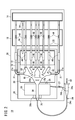
- the procedure simulator 10 includes a first storage tank 12, a second storage tank 14, a third storage tank 16, a tissue model 18, a pump 20, a pipe 22, and a catheter introduction member 24.
- the first storage tank 12, the second storage tank 14, the third storage tank 16, the tissue model 18, the pump 20, and the pipe 22 are arranged on the flat support plate 26.
- At least each of the first storage tank 12, the second storage tank 14, the third storage tank 16, the tissue model 18, and the pump 20 can be mounted on the support plate 26, so that it is easy to carry and set. It becomes.
- a tray 28 is placed on the support plate 26.
- the tray 28 is a plate-shaped member for collectively supporting the first storage tank 12, the tissue model 18, and the pump 20, and the first storage tank 12 is arranged on one end side thereof.
- a support column 28a for supporting the upstream portion (starting end portion 36) of the tissue model 18 is provided on the other end side of the tray 28.
- a pump 20 is arranged between the support column 28a of the tray 28 and the first storage tank 12.
- the first storage tank 12 is removable from the tray 28.
- the first storage tank 12 is a container for storing a liquid to be introduced into the tissue model 18, and is formed in a rectangular shape in a plan view.
- the first storage tank 12 is arranged below the tissue model 18.
- the first storage tank 12 is formed of a resin material such as an acrylic resin.
- the first storage tank 12 may have an opening at the upper end thereof.
- the pump 20 is composed of, for example, a centrifugal pump or the like, and pumps the liquid stored in the first storage tank 12 into the tissue model 18 provided above the first storage tank 12. As shown in FIG. 2, the suction port of the pump 20 is connected to the first storage tank 12 via the suction flow path 29. One end of the discharge pipe 27 is connected to the discharge port of the pump 20. The other end of the discharge pipe 27 is connected to the liquid supply port 24b branched from the introduction port 24a of the catheter introduction member 24.
- the catheter introduction member 24 includes a flexible tubular main body portion 24c and an introduction port 24a provided on the proximal end side of the main body portion 24c.
- the tip end side of the main body 24c is connected to the start end 36 of the tissue model 18, and the introduction port 24a and the liquid supply port 24b communicate with the flow path 38 of the tissue model 18 through the main body 24c.
- the liquid discharged from the pump 20 is sent to the start end portion 36 of the tissue model 18 via the catheter introduction member 24.
- the introduction port 24a simulates an insertion port into which the catheter 60 is inserted into a blood vessel.
- a catheter 60 can be inserted into the introduction port 24a, but a valve (not shown) is provided so that the liquid inside the catheter introduction member 24 does not leak.
- the tissue model 18 is arranged on the first storage tank 12.
- the structure model 18 is mounted on the plate-shaped support member 30.
- the support member 30 is a flat plate-shaped member spanned so as to cover a part of the upper end opening of the first storage tank 12, and is inserted into the engagement hole 18a of the tissue model 18 on the upper surface side thereof.
- a protrusion 30a is provided.
- Piping guides 31 that guide the bent portions of the piping 22 are provided on both sides of the support member 30.
- the piping guide 31 is a U-shaped groove capable of holding the piping 22 inside.
- the piping guide 31 has a pair of side wall portions 31a curved in an arc shape in a plan view, and holds the piping 22 in a curved state along the piping guide 31 between the pair of side wall portions 31a. This prevents the pipe 22 from being blocked.
- the structure model 18 is simply fixed on the support member 30 through the pipe 22 held by the pipe guide 31 while the engaging hole 18a fits into the protrusion 30a.
- the structure model 18 is provided on the flow path forming block 32 made of a transparent material such as acrylic resin.
- the structure model 18 may be made of a soft material (rubber material) such as a silicon resin.
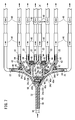
- the flow path forming block 32 constituting the structure model 18 has a plurality of branching portions 34, and as shown in the drawing, branches from the starting end portion 36 on the upstream side toward the downstream side in a dendrogram pattern. , Branches into eight branch flow paths 42.
- a branch portion 34a is formed in a portion closest to the start end portion 36, and the flow path 38 branches into two branch flow paths 40a and 40b at the branch portion 34a.
- the branch flow paths 40a and 40b are branched at an angle symmetrical to the left and right with respect to the flow path 38 on the upstream side of the branch portion 34a, and are formed to have the same length as each other.
- Branch portions 34b and 34c are formed at the ends (downstream ends) of the branch flow paths 40a and 40b, respectively.
- the branch flow path 40a branches into two branch flow paths 40c and 40d.
- the branch flow paths 40c and 40d branch to the left and right at an angle symmetrical with respect to the traveling direction of the branch flow path 40a on the upstream side.
- the branch flow path 40b branches into two branch flow paths 40e and 40f.
- the branch flow paths 40e and 40f branch to the left and right at an angle symmetrical with respect to the traveling direction of the branch flow path 40b on the upstream side.
- the branch flow paths 40c to 40f are formed to have substantially equal lengths.
- Each branch portion 34d to 34g is formed at the end of the branch flow path 40c to 40f.
- each of the branch flow paths 40c to 40f further branches into two branch flow paths 42. That is, the structure model 18 finally branches into eight branch flow paths 42.
- the branch flow paths 42 are branched to the left and right at the same angle with respect to the branch flow paths 40c to 40f on the upstream side, and the eight branch flow paths 42 are formed to have substantially the same length.
- each branch flow path 42 in the structure model 18 can have the same flow rate.
- Each of the eight bifurcation channels 42 mimics eight arteries leading to subzones S1 to S8 of the liver 100 (see FIG. 1).
- a plurality of connecting flow paths 45 for connecting the branch flow paths 40a to 40f and 42 are provided downstream of the branch portions 34a to 34g. These connecting flow paths 45 imitate the collateral circulation of the tissue.
- the branch flow paths 40a to 40f and 42 inside the structure model 18 are formed so as to be thinned to about 70 to 90% of the inner diameter before branching each time the branch passages 40a to 40f and 42g pass through the branch portions 34a to 34g. It is preferable that the inner diameter after branching is 80% (78 to 82%) of the inner diameter before branching in order to bring it closer to the human tubular tissue.
- the inner diameter of the branch flow paths 40a and 40b are about 4 mm, and the inner diameters of the branch flow paths 40c to 40f are about 3.3 mm, respectively.
- the inner diameter of the branch flow path 42 can be about 2.8 mm.
- the inner diameter of the connecting flow path 45 can be about 1.5 to 1.8 mm.
- each resin plate has a flow path 38, branch flow paths 40a to 40f, 42, and a connection flow path 45. Form a groove corresponding to. Then, the structure model 18 is produced by superimposing and joining two resin plates so that the grooves are aligned with each other.
- connection ports 44 as outlets of the branch flow path 42 are provided. As shown in FIG. 2, one end of the pipe 22 is connected to those connection ports 44. Eight pipes 22 are provided corresponding to the eight branch flow paths 42.
- the pipe 22 extends toward the second storage tank 14, and the other end of the pipe 22 is connected to the connection port 52 of the second storage tank 14.
- the pipes 22 on both sides that are largely inclined from the direction toward the second storage tank 14 are guided by the pipe guide 31 and curved in the direction toward the second storage tank 14.
- Each pipe 22 is provided with a filter member 46 and a three-way stopcock 48.
- the filter member 46 is provided on the upstream side of the three-way stopcock 48 (that is, on the tissue model 18 side of the three-way stopcock 48), and simulates cancer cells.
- the filter members 46 are arranged side by side on the first storage tank 12. As shown in FIG. 5, the filter member 46 includes a cylindrical casing 46a and a filter 46b filled inside the casing 46a.
- the casing 46a is formed of a material such as a transparent resin material whose inside can be visually recognized so that the discoloration of the filter 46b can be visually recognized.
- the filter 46b is made of a white or pale colored material and is colored when passed through a colorant imitating a therapeutic agent or a colored embolic agent.
- the user can confirm that the therapeutic agent has reached the target site by visually recognizing the coloring of the filter 46b.
- the embolic agent is flowed into the casing 46a of the filter member 46, it can be visually recognized that the embolic agent gradually accumulates in the filter 46b. Further, it can be visually recognized that as the embolization of the filter 46b progresses, the inflow rate of the embolic agent flowing into the filter 46b decreases. This phenomenon simulates a change in liquid flow similar to the phenomenon in which an embolic agent accumulates in cancer / tumor tissue in an actual living body.
- the filter 46b is detachably connected to the pipe 22. That is, the filter 46b can be used as a disposable member, and in this case, only the filter 46b can be removed from the procedure simulator 10 and discarded.
- a drain flow path 50 for discharging the liquid discharged from the branch flow path 42 to a portion lower than the tissue model 18 is connected to the three-way stopcock 48.
- the three-way stopcock 48 selectively communicates the branch flow path 42 with the second storage tank 14 and the drain flow path 50.
- the branch flow path 42 communicates with the second storage tank 14 by the three-way stopcock 48
- the liquid flows into the second storage tank 14 through the pipe 22.
- the branch flow path 42 communicates with the drain flow path 50 by the three-way stopcock 48
- the liquid discharged from the branch flow path 42 is discharged from a position lower than the structure model 18 via the drain flow path 50.
- the liquid is discharged from the drain flow path 50 by switching the flow path with the three-way stopcock 48.
- the liquid discharged from the drain flow path 50 is stored in the third storage tank 16.
- the second storage tank 14 is a storage tank formed in a rectangular shape in a plan view, and stores the liquid discharged from the pipe 22.
- the volume of the second storage tank 14 is smaller than the volume of the first storage tank 12.
- the second storage tank 14 is provided by the pedestal 14a so that the position of the bottom surface thereof is near the upper end of the first storage tank 12.
- the second storage tank 14 is removable from the support plate 26 or the pedestal 14a.
- the second storage tank 14 includes eight connection ports 52 provided near the bottom and one discharge port 54 provided near the upper end.
- the eight connection ports 52 are provided at the same height, and the downstream end of the pipe 22 is connected to each of the eight connection ports 52.
- An upstream end of the return pipe 56 is connected to the discharge port 54.
- the downstream end of the reflux pipe 56 is arranged inside the first storage tank 12.
- the liquid is stored up to the height of the discharge port 54.
- the liquid is discharged from the second storage tank 14 through the discharge port 54.
- the liquid discharged from the discharge port 54 flows through the return pipe 56 due to the head and returns to the first storage tank 12.
- the third storage tank 16 is a storage tank arranged between the first storage tank 12 and the second storage tank 14, and is formed in a rectangular shape in a plan view.
- the end of the drain flow path 50 is arranged inside the third storage tank 16.
- the third storage tank 16 stores the liquid discharged from the drain flow path 50.
- the third storage tank 16 is formed of a transparent material such as an acrylic resin, and by arranging a lighting means such as a reflector or a flat light emitting device on the lower surface side, the third storage tank 16 is under the pipe 22 and the filter member 46. Illumination light can be emitted from.
- the third storage tank 16 may be detachably fixed to the support plate 26.
- the catheter 60 for use in the procedure simulator 10 includes a catheter body 62, a balloon 64 provided at the tip of the catheter body 62 that can be expanded and contracted, and a proximal end of the catheter body 62.
- a hub 66 connected to the unit is provided.
- the balloon 64 communicates with the expansion port 68 provided in the hub 66 via an expansion lumen provided in the catheter body 62.
- the balloon 64 is expanded by injecting the expansion liquid from the expansion port 68. Note that FIG. 6 shows the balloon 64 in the expanded state.
- the expansion liquid is injected using a syringe or the like.
- Hub 66 has an injection port 72 for injecting a therapeutic agent into a blood vessel extending to a target area.
- the injection port 72 communicates with the terminal opening 70 of the catheter 60 via an injection lumen provided inside the catheter body 62.
- the therapeutic agent injected from the injection port 72 is introduced into the blood vessel through the terminal opening 70.
- the injection lumen also functions as a guide wire lumen.
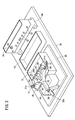
- the user puts the liquid in the first storage tank 12 after assembling the procedure simulator 10 as shown in FIG.
- the liquid is preferably transparent and can be easily obtained and cleaned up (tap water) in order to visually recognize the change in the flow of the colored therapeutic agent or colored water due to the pressure gradient. ..
- the user drives the pump 20 after confirming that the three-way stopcock 48 of all the pipes 22 communicates with the second storage tank 14.
- the pump 20 pumps the liquid from the first storage tank 12 and supplies the liquid to the tissue model 18 via the catheter introduction member 24.
- the liquid flows through the flow path 38, the branch flow paths 40a to 40f, and 42 of the tissue model 18, and is stored in the second storage tank 14 via the pipe 22.
- the liquid in the second storage tank 14 returns to the first storage tank 12 via the return pipe 56.
- the pump 20 allows the liquid in the first storage tank 12 to return to the first storage tank 12 via the catheter introduction member 24, the tissue model 18, the pipe 22, the second storage tank 14, and the reflux pipe 56. And it keeps circulating.
- the liquid level of the liquid is maintained at the position of the discharge port 54. Therefore, a water pressure corresponding to the difference ⁇ H1 between the height of the tissue model 18 and the height of the liquid level of the second storage tank 14 acts on the branch flow paths 40a to 40f and 42 inside the structure model 18. In this state, the liquid flows through each branch flow path 42 of the tissue model 18 at substantially the same flow rate, and the flow of a healthy hepatic artery 102 without cancer tissue can be simulated.
- the user inserts the catheter 60 into the tissue model 18 via the catheter introduction member 24.
- the user can confirm the behavior of the simulated therapeutic agent when the simulated therapeutic agent is administered from the terminal opening 70 of the catheter 60 in a state where the balloon 64 is not expanded.
- the user can visually recognize the flow of the healthy hepatic artery 102 by injecting colored colored water as a simulated therapeutic agent.
- the user operates a three-way stopcock 48 of the pipe 22 connected to the predetermined branch flow path 42 to communicate the branch flow path 42 with the drain flow path 50.
- the liquid in the predetermined branch flow path 42 is discharged from the end portion of the drain flow path 50 located at a position lower than that of the tissue model 18.
- the water pressure in the predetermined branch flow path 42 is reduced by the amount corresponding to the head ⁇ H2 between the structure model 18 and the liquid level of the third storage tank 16. Therefore, a pressure difference corresponding to the difference of ⁇ H1 + ⁇ H2 is generated between the branch flow path 42 communicating with the second storage tank 14 and the branch flow path 42 communicating with the drain flow path 50.
- the user injects colored water from the terminal opening 70 of the catheter 60 in a state where the balloon 64 is not expanded.
- the colored water flows to all the branch flow paths 42 on the downstream side of the terminal opening 70. This is because the water pressure sent out by the pump 20 is higher than the internal pressure of the branch flow path 42 communicating with the drain flow path 50 and the branch flow path 42 communicating with the second storage tank 14.
- the user expands the balloon 64 of the catheter 60 upstream of the branch portion 34b to block the branch flow path 40a and the connecting flow path 45 on the upstream side of the branch portion 34b.
- the behavior of the simulated therapeutic agent in the case can be visually recognized.
- the user injects colored water from the terminal opening 70 of the catheter body 62 with the balloon 64 expanded. Colored water mimics a contrast or therapeutic agent. Since the branch flow path 40a and the connecting flow path 45 on the upstream side are blocked by the balloon 64, the branch flow paths 40a, 40c, 40d, and 42 on the downstream side of the balloon 64 may receive pressure from the pump 20. do not have.
- the pressure of the branch flow path 42 communicating with the second storage tank 14 is relatively higher than the pressure of the branch flow path 42 communicating with the drain flow path 50.
- the liquid is drawn from the branch flow path 42 communicating with the second storage tank 14 toward the branch flow path 42 communicating with the drain flow path 50.
- the backflow of the liquid in the second storage tank 14 from the branch flow path 42 communicating with the second storage tank 14 stably creates a state in which the liquid flows only into the branch flow path 42 communicating with the drain flow path 50. Can be done.
- This state is maintained for a relatively long time until the liquid in the first storage tank 12 runs out. Therefore, the user can perform training such as changing the closed position of the balloon 64 to various positions and changing the position of the branch flow path 42 communicating with the drain flow path 50. This allows the user to deepen their understanding of the behavior of the simulated therapeutic agent.
- the colored water flowing into the branch flow path 42 communicating with the drain flow path 50 stains the filter member 46 when passing through the filter member 46 simulating the cancer tissue.
- the user can visually recognize that the therapeutic agent has selectively reached the cancer tissue.
- the colored water may contain a solid embolic substance.
- the solid embolic substance gelatin, spherical plastic (beads), fluorescent pieces and the like are preferably used.
- the user can confirm how the filter member 46 is gradually clogged, and changes in the blood flow when the filter member 46 as a simulated tumor tissue is clogged. Can be grasped.
- the procedure simulator 10 of this embodiment has the following effects.
- the first storage tank 12 for storing the liquid imitating the blood of the present embodiment and the plurality of branch passages 40a to 40f, 42 branching downstream through the plurality of branch portions 34a to 34g, and the branch portions 34a to 34a to
- the structure model 18 in which 34 g and the branch flow paths 40a to 40f and 42 are formed at the same height, the pump 20 that supplies the liquid in the first storage tank 12 to the structure model 18, and the liquid that flows out from the branch flow path 42.
- a second storage tank 14 for storing, a pipe 22 connecting the outlet of the branch flow path 42 and the second storage tank 14, and a drain provided in the middle of the pipe 22 to discharge the liquid below the second storage tank 14.
- a three-way stopcock 48 that selectively communicates the branch flow path 42 with the flow path 50 is provided in the middle of the pipe 22 between the three-way stopcock 48 and the outlet of the branch flow path 42, and the inside can be visually recognized. It includes a filter member 46.
- the branch flow path 42 communicating with the drain flow path 50 and the branch flow path 42 not communicating with the drain flow path 50 by operating the three-way stopcock 48 (switching valve).
- a pressure gradient can be generated in the cancer tissue, and the cancer tissue can be simulated by the filter member 46 provided on the downstream side of the branch flow path 42. Then, by visually recognizing the filter member 46, it is possible to realize that the therapeutic agent can be selectively administered to a specific site.
- the pipe 22 may be connected near the lower end of the second storage tank 14, and the second storage tank 14 may be configured to maintain the liquid level at a position higher than the tissue model 18. ..
- a pressure corresponding to the difference ⁇ H1 between the liquid level of the second storage tank 14 and the height of the tissue model 18 acts on the branch flow path 42 communicating with the second storage tank 14.
- the pipe 22 may be connected to the second storage tank 14 at the same height as the tissue model 18. With this configuration, the flow resistance and pressure acting on each branch flow path 42 of the structure model 18 can be made uniform.
- the above-mentioned procedure simulator 10 may be provided with a recirculation pipe 56 which is connected to the second storage tank 14 at a position higher than the pipe 22 and returns the liquid of the second storage tank 14 to the first storage tank 12.
- a recirculation pipe 56 which is connected to the second storage tank 14 at a position higher than the pipe 22 and returns the liquid of the second storage tank 14 to the first storage tank 12.
- the filter members 46 provided in each branch flow path 42 are arranged side by side in a row on the downstream side of the tissue model 18. As a result, the user can easily visually recognize the difference between the filter member 46 simulating the tumor and the other filter member 46.
- a third storage tank 16 for accommodating the liquid discharged from the drain flow path 50 is provided, and the liquid level of the third storage tank 16 can be set at a position lower than that of the tissue model 18.
- the difference ⁇ H1 and the liquid level of the third storage tank 16 and the structure model 18 are separated from each other.
- a pressure difference corresponding to the sum of the head ⁇ H2 can be generated.
- the second storage tank 14 is provided at a position horizontally separated from the tissue model 18, and the third storage tank 16 is arranged between the second storage tank 14 and the tissue model 18. May be good.
- the third storage tank 16 can be arranged below the three-way stopcock 48, and the routing of the drain flow path 50 can be simplified.
- the first storage tank 12 may be arranged under the tissue model 18.
- the organization model 18 of the procedure simulator 10 is compactly arranged.
- the tissue model 18 and the pipe 22 may be formed of a transparent material.
- the user can directly visually recognize the flow of the colored water and can easily realize that the therapeutic agent can be selectively administered to a specific site.
- the procedure training method of the present embodiment is a procedure training method using the above-mentioned procedure simulator 10, and the step of filling the first storage tank 12 with the liquid and the pump 20 are driven to store the liquid in the first storage.
- the liquid is drained through the step of circulating between the tank 12, the structure model 18, and the second storage tank 14 and the three-way activation plug 48 (switching valve) of the pipe 22 connected to the outlet of the predetermined branch flow path 42.
- a pressure gradient can be generated between the branch flow paths 42, and the cancer tissue can be simulated by the filter member 46. Then, by flowing colored water from the tip of the balloon 64, it is possible to realize that the therapeutic agent can be selectively administered to the filter member 46 that imitates the cancer tissue.
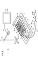
- an image pickup device 76 that images the tissue model 18 and the pipe 22 and an image captured by the image pickup device 76 are further provided. It has a display device 78 for displaying.
- the image pickup device 76 is composed of, for example, a smartphone, a small camera, or the like, and is arranged above the tissue model 18 and the pipe 22 by the stand 80. Under the third storage tank 16, a planar lighting device for illuminating the tissue model 18, the pipe 22, and the filter member 46 may be provided.
- the image pickup apparatus 76 captures an image of the tissue model 18 and the pipe 22 as viewed from above.
- the image pickup device 76 is connected to the display device 78 via a communication cable 82 such as a USB cable, and the video data captured by the image pickup device 76 is sent to the display device 78.
- the display device 78 is a device having a relatively large display screen 78a, and for example, a liquid crystal monitor, a screen, a tablet terminal, or the like can be used.
- the image (video) captured by the image pickup device 76 is displayed in real time on the display screen 78a of the display device 78.
- the procedure simulator 10A of the present embodiment can also be used for training to operate the catheter 60 while viewing a flat image appearing on the display screen 78a of the display device 78.
- the operation of the catheter 60 and the flow of colored water can be grasped under conditions close to the actual procedure performed while looking at the X-ray fluoroscope.
- stomach Even when a cancer / tumor tissue formed in an organ other than the liver is targeted, the present invention can be carried out by combining tissue models according to the target organ.
Landscapes
- Engineering & Computer Science (AREA)
- Physics & Mathematics (AREA)
- General Physics & Mathematics (AREA)
- Health & Medical Sciences (AREA)
- Mathematical Analysis (AREA)
- Pure & Applied Mathematics (AREA)
- Medical Informatics (AREA)
- Algebra (AREA)
- Computational Mathematics (AREA)
- General Health & Medical Sciences (AREA)
- Chemical & Material Sciences (AREA)
- Mathematical Optimization (AREA)
- Mathematical Physics (AREA)
- Medicinal Chemistry (AREA)
- Business, Economics & Management (AREA)
- Educational Administration (AREA)
- Educational Technology (AREA)
- Theoretical Computer Science (AREA)
- Radiology & Medical Imaging (AREA)
- Pulmonology (AREA)
- Nuclear Medicine, Radiotherapy & Molecular Imaging (AREA)
- Instructional Devices (AREA)
Abstract
Description
本実施形態は、肝臓癌の治療を模擬する手技シミュレータ10(図2参照)について説明する。
図9に示すように、本実施形態に係る手技シミュレータ10Aは、図2に示す装置構成に加えて、さらに、組織モデル18及び配管22を撮像する撮像装置76と、撮像装置76が撮像した映像を表示する表示装置78とを有している。
Claims (11)
- 液体を貯留する第1貯留槽と、
複数の分岐部を通じて下流に向けて複数の分岐流路に分岐し、且つ前記分岐部及び前記分岐流路が同じ高さに形成された組織モデルと、
前記第1貯留槽の前記液体を前記組織モデルに供給するポンプと、
前記分岐流路から流出する前記液体を貯留する第2貯留槽と、
前記分岐流路の出口と前記第2貯留槽とを繋ぐ配管と、
前記配管の途上に設けられ、前記第2貯留槽よりも下方に前記液体を排出するドレイン流路に前記分岐流路を選択的に連通させる切換弁と、
前記切換弁と前記分岐流路の出口との間の前記配管の途上に設けられたフィルタ部材と、を備えた、手技シミュレータ。 - 請求項1記載の手技シミュレータであって、前記配管は前記第2貯留槽の下端付近に接続され、前記第2貯留槽は、前記組織モデルより高い位置に前記液体の液面を維持する、手技シミュレータ。
- 請求項2記載の手技シミュレータであって、前記配管は、前記組織モデルと同じ高さで前記第2貯留槽に接続される、手技シミュレータ。
- 請求項3記載の手技シミュレータであって、前記配管よりも高い位置で前記第2貯留槽に接続され、前記第2貯留槽の前記液体を前記第1貯留槽に還流させる還流配管を備えた、手技シミュレータ。
- 請求項1~3の何れか1項に記載の手技シミュレータであって、各々の前記分岐流路に設けられた前記フィルタ部材が一列に並んで配置される、手技シミュレータ。
- 請求項1~4の何れか1項に記載の手技シミュレータであって、前記ドレイン流路から排出される前記液体を収容する第3貯留槽を備え、該第3貯留槽の液面は、前記組織モデルよりも低い位置にある、手技シミュレータ。
- 請求項6記載の手技シミュレータであって、前記第2貯留槽は前記組織モデルから水平方向に離間した位置に設けられ、前記第3貯留槽は前記第2貯留槽と前記組織モデルとの間に配置される、手技シミュレータ。
- 請求項1~7の何れか1項に記載の手技シミュレータであって、前記第1貯留槽は前記組織モデルの下に配置される、手技シミュレータ。
- 請求項1~8の何れか1項に記載の手技シミュレータであって、前記組織モデル及び前記配管を撮像する撮像装置と、前記撮像装置が撮像した映像を表示する表示装置と、を備えた、手技シミュレータ。
- 請求項9記載の手技シミュレータであって、さらに、前記組織モデル、前記配管及び前記フィルタ部材を照明する照明装置を備えた、手技シミュレータ。
- 液体を貯留する第1貯留槽と、
複数の分岐部を通じて下流に向けて複数の分岐流路に分岐し、且つ前記分岐部及び前記分岐流路が同じ高さに形成された組織モデルと、
前記第1貯留槽の前記液体を前記組織モデルに供給するポンプと、
前記分岐流路から流出する前記液体を貯留する第2貯留槽と、
前記分岐流路の出口と前記第2貯留槽とを繋ぐ配管と、
前記配管の途上に設けられ、前記第2貯留槽よりも下方に前記液体を排出するドレイン流路に前記分岐流路を選択的に連通させる切換弁と、
前記切換弁と前記分岐流路の出口との間の前記配管の途上に設けられたフィルタ部材と、を備えた、手技シミュレータを用いた、手技訓練方法であって、
前記第1貯留槽に前記液体を満たすステップと、
前記ポンプを駆動させて、前記液体を、前記第1貯留槽、前記組織モデル、前記第2貯留槽の間で循環させるステップと、
所定の前記分岐流路の出口に接続された前記配管の前記切換弁を介して前記液体を前記ドレイン流路から排出させるステップと、
前記組織モデルにカテーテルを挿入し、前記ドレイン流路に連通する前記分岐流路の上流部をバルーンで閉塞するステップと、
前記バルーンの先端から造影剤又は治療剤を流すステップと、
を有する手技訓練方法。
Priority Applications (5)
| Application Number | Priority Date | Filing Date | Title |
|---|---|---|---|
| EP21750616.1A EP4086879A4 (en) | 2020-02-04 | 2021-01-12 | Procedure simulator, and procedure practice method using same |
| JP2021575674A JPWO2021157285A1 (ja) | 2020-02-04 | 2021-01-12 | |
| AU2021215474A AU2021215474A1 (en) | 2020-02-04 | 2021-01-12 | Procedure simulator and procedure training method using the same |
| CN202180005945.0A CN114556458B (zh) | 2020-02-04 | 2021-01-12 | 手术操作模拟器以及使用该手术操作模拟器的手术操作训练方法 |
| US17/816,479 US20220392374A1 (en) | 2020-02-04 | 2022-08-01 | Procedure simulator and procedure training method using the same |
Applications Claiming Priority (2)
| Application Number | Priority Date | Filing Date | Title |
|---|---|---|---|
| JP2020017102 | 2020-02-04 | ||
| JP2020-017102 | 2020-02-04 |
Related Child Applications (1)
| Application Number | Title | Priority Date | Filing Date |
|---|---|---|---|
| US17/816,479 Continuation US20220392374A1 (en) | 2020-02-04 | 2022-08-01 | Procedure simulator and procedure training method using the same |
Publications (1)
| Publication Number | Publication Date |
|---|---|
| WO2021157285A1 true WO2021157285A1 (ja) | 2021-08-12 |
Family
ID=77200465
Family Applications (1)
| Application Number | Title | Priority Date | Filing Date |
|---|---|---|---|
| PCT/JP2021/000614 WO2021157285A1 (ja) | 2020-02-04 | 2021-01-12 | 手技シミュレータ及びそれを用いた手技訓練方法 |
Country Status (6)
| Country | Link |
|---|---|
| US (1) | US20220392374A1 (ja) |
| EP (1) | EP4086879A4 (ja) |
| JP (1) | JPWO2021157285A1 (ja) |
| CN (1) | CN114556458B (ja) |
| AU (1) | AU2021215474A1 (ja) |
| WO (1) | WO2021157285A1 (ja) |
Cited By (1)
| Publication number | Priority date | Publication date | Assignee | Title |
|---|---|---|---|---|
| WO2023239859A1 (en) * | 2022-06-10 | 2023-12-14 | The Johns Hopkins University | Apparatus for developing and testing devices and methods for embolizing a blood vessel |
Citations (8)
| Publication number | Priority date | Publication date | Assignee | Title |
|---|---|---|---|---|
| US20150161347A1 (en) * | 2011-09-13 | 2015-06-11 | Medtronic Inc. | Physiologic simulator system |
| JP2016057451A (ja) * | 2014-09-09 | 2016-04-21 | テルモ株式会社 | トレーニング装置 |
| WO2016075732A1 (ja) * | 2014-11-10 | 2016-05-19 | 国立大学法人大阪大学 | カテーテル・シミュレーター、及びカテーテル・シミュレーター用造影方法 |
| JP2017140334A (ja) * | 2016-02-12 | 2017-08-17 | 学校法人早稲田大学 | 医療用試験対象物の耐久性試験装置及び耐久性試験方法 |
| US9844383B2 (en) | 2013-05-08 | 2017-12-19 | Embolx, Inc. | Devices and methods for low pressure tumor embolization |
| US9852660B1 (en) * | 2015-12-03 | 2017-12-26 | Robert Fairbanks | Catheterization procedure training apparatus |
| WO2019005868A1 (en) * | 2017-06-26 | 2019-01-03 | Mentice, Inc. | SYSTEMS AND METHODS FOR ENDOVASCULAR FLUID INJECTION SIMULATIONS |
| WO2020031474A1 (ja) * | 2018-08-07 | 2020-02-13 | テルモ株式会社 | 手技シミュレータ |
Family Cites Families (7)
| Publication number | Priority date | Publication date | Assignee | Title |
|---|---|---|---|---|
| GB9615802D0 (en) * | 1996-07-26 | 1996-09-04 | Harris P L | Simulation system |
| AU2006203753A1 (en) * | 2005-09-06 | 2007-03-22 | Thoratec Corporation | Mock Circulatory Apparatus |
| US8608484B2 (en) * | 2008-03-04 | 2013-12-17 | Medrad, Inc. | Dynamic anthropomorphic cardiovascular phantom |
| JP6317885B2 (ja) * | 2013-03-01 | 2018-04-25 | テルモ株式会社 | トレーニング装置 |
| JP6454527B2 (ja) * | 2014-12-02 | 2019-01-16 | 株式会社ブリヂストン | 貯留槽、サイホン式排水システム及び流出管接続部材 |
| DE102016108152A1 (de) * | 2016-05-02 | 2017-11-02 | Universität Zu Lübeck | Dreidimensionales gefäßchirurgisches-Simulationsmodell sowie dazugehöriges Herstellungsverfahren |
| CN206194241U (zh) * | 2016-08-17 | 2017-05-24 | 有研医疗器械(北京)有限公司 | 一种主动脉微创介入手术模拟装置 |
-
2021
- 2021-01-12 EP EP21750616.1A patent/EP4086879A4/en active Pending
- 2021-01-12 AU AU2021215474A patent/AU2021215474A1/en active Pending
- 2021-01-12 WO PCT/JP2021/000614 patent/WO2021157285A1/ja unknown
- 2021-01-12 JP JP2021575674A patent/JPWO2021157285A1/ja active Pending
- 2021-01-12 CN CN202180005945.0A patent/CN114556458B/zh active Active
-
2022
- 2022-08-01 US US17/816,479 patent/US20220392374A1/en active Pending
Patent Citations (8)
| Publication number | Priority date | Publication date | Assignee | Title |
|---|---|---|---|---|
| US20150161347A1 (en) * | 2011-09-13 | 2015-06-11 | Medtronic Inc. | Physiologic simulator system |
| US9844383B2 (en) | 2013-05-08 | 2017-12-19 | Embolx, Inc. | Devices and methods for low pressure tumor embolization |
| JP2016057451A (ja) * | 2014-09-09 | 2016-04-21 | テルモ株式会社 | トレーニング装置 |
| WO2016075732A1 (ja) * | 2014-11-10 | 2016-05-19 | 国立大学法人大阪大学 | カテーテル・シミュレーター、及びカテーテル・シミュレーター用造影方法 |
| US9852660B1 (en) * | 2015-12-03 | 2017-12-26 | Robert Fairbanks | Catheterization procedure training apparatus |
| JP2017140334A (ja) * | 2016-02-12 | 2017-08-17 | 学校法人早稲田大学 | 医療用試験対象物の耐久性試験装置及び耐久性試験方法 |
| WO2019005868A1 (en) * | 2017-06-26 | 2019-01-03 | Mentice, Inc. | SYSTEMS AND METHODS FOR ENDOVASCULAR FLUID INJECTION SIMULATIONS |
| WO2020031474A1 (ja) * | 2018-08-07 | 2020-02-13 | テルモ株式会社 | 手技シミュレータ |
Non-Patent Citations (3)
| Title |
|---|
| IRIE ET AL.: "Dense Accumulation of Lipiodol Emulsion in Hepatocellular Carcinoma Nodule during Selective Balloon-occluded Arterial Stump Pressure", CARDIO VASCULAR AND INTERVENTION RADIOLOGY, vol. 36, 2013, pages 706 - 713 |
| MATSUMOTO ET AL.: "Balloon-occluded arterial stump pressure before balloon-occluded transarterial chemoembolization", MINIMALLY INVASIVE THERAPY & ALLIED TECHNOLOGIES, vol. 25, 25 September 2015 (2015-09-25), Retrieved from the Internet <URL:https://doi.org/10.3109/13645706.2015.1086381> |
| See also references of EP4086879A4 |
Cited By (1)
| Publication number | Priority date | Publication date | Assignee | Title |
|---|---|---|---|---|
| WO2023239859A1 (en) * | 2022-06-10 | 2023-12-14 | The Johns Hopkins University | Apparatus for developing and testing devices and methods for embolizing a blood vessel |
Also Published As
| Publication number | Publication date |
|---|---|
| JPWO2021157285A1 (ja) | 2021-08-12 |
| US20220392374A1 (en) | 2022-12-08 |
| AU2021215474A1 (en) | 2022-06-23 |
| EP4086879A1 (en) | 2022-11-09 |
| CN114556458B (zh) | 2024-01-30 |
| EP4086879A4 (en) | 2023-06-28 |
| CN114556458A (zh) | 2022-05-27 |
Similar Documents
| Publication | Publication Date | Title |
|---|---|---|
| JP7280268B2 (ja) | 手技シミュレータ | |
| US6790043B2 (en) | Method and apparatus for surgical training | |
| US6517354B1 (en) | Medical simulation apparatus and related method | |
| CA2592694C (en) | Retrograde perfusion of tumor sites | |
| JP6452715B2 (ja) | カテーテル・シミュレーター、及びカテーテル・シミュレーター用造影方法 | |
| CN103886798B (zh) | 一种高度仿真介入手术训练器 | |
| JP5749909B2 (ja) | 模擬人体 | |
| JP7054112B2 (ja) | カテーテル・シミュレーター用臓器モデル | |
| JP6202562B2 (ja) | シミュレーションシステム、及びステントグラフトの設置シミュレーション方法 | |
| EP2772897A1 (en) | Medical training apparatus for catheterization | |
| US9033713B2 (en) | Method and device for injecting a fluid into an artificial venous structure | |
| WO2021157285A1 (ja) | 手技シミュレータ及びそれを用いた手技訓練方法 | |
| CA2951568A1 (en) | Selectively delivering particles into the distal portion of the left gastric artery | |
| JPH0550477U (ja) | 心臓血管模型 | |
| JP2017111340A (ja) | 手技シミュレータ | |
| Baron et al. | Endoscopic ultrasound–guided cholecystoduodenostomy for acute cholecystitis in a patient with thrombocytopenia and end-stage liver disease awaiting transplantation | |
| BR112020004395A2 (pt) | dispositivo de formação de imagem para uso em intervenções médicas. | |
| IL147954A (en) | Method and device for demonstrating intravenous and extracorporeal data in various parts of the circulatory system for testing devices for intravenous use |
Legal Events
| Date | Code | Title | Description |
|---|---|---|---|
| 121 | Ep: the epo has been informed by wipo that ep was designated in this application |
Ref document number: 21750616 Country of ref document: EP Kind code of ref document: A1 |
|
| ENP | Entry into the national phase |
Ref document number: 2021575674 Country of ref document: JP Kind code of ref document: A |
|
| ENP | Entry into the national phase |
Ref document number: 2021215474 Country of ref document: AU Date of ref document: 20210112 Kind code of ref document: A |
|
| ENP | Entry into the national phase |
Ref document number: 2021750616 Country of ref document: EP Effective date: 20220803 |
|
| NENP | Non-entry into the national phase |
Ref country code: DE |