WO2021149810A1 - Panneau - Google Patents
Panneau Download PDFInfo
- Publication number
- WO2021149810A1 WO2021149810A1 PCT/JP2021/002285 JP2021002285W WO2021149810A1 WO 2021149810 A1 WO2021149810 A1 WO 2021149810A1 JP 2021002285 W JP2021002285 W JP 2021002285W WO 2021149810 A1 WO2021149810 A1 WO 2021149810A1
- Authority
- WO
- WIPO (PCT)
- Prior art keywords
- panel
- steel sheet
- martensite
- flat portion
- steel
- Prior art date
Links
Images


Classifications
-
- C—CHEMISTRY; METALLURGY
- C21—METALLURGY OF IRON
- C21D—MODIFYING THE PHYSICAL STRUCTURE OF FERROUS METALS; GENERAL DEVICES FOR HEAT TREATMENT OF FERROUS OR NON-FERROUS METALS OR ALLOYS; MAKING METAL MALLEABLE, e.g. BY DECARBURISATION OR TEMPERING
- C21D8/00—Modifying the physical properties by deformation combined with, or followed by, heat treatment
- C21D8/02—Modifying the physical properties by deformation combined with, or followed by, heat treatment during manufacturing of plates or strips
- C21D8/0278—Modifying the physical properties by deformation combined with, or followed by, heat treatment during manufacturing of plates or strips involving a particular surface treatment
-
- C—CHEMISTRY; METALLURGY
- C21—METALLURGY OF IRON
- C21D—MODIFYING THE PHYSICAL STRUCTURE OF FERROUS METALS; GENERAL DEVICES FOR HEAT TREATMENT OF FERROUS OR NON-FERROUS METALS OR ALLOYS; MAKING METAL MALLEABLE, e.g. BY DECARBURISATION OR TEMPERING
- C21D9/00—Heat treatment, e.g. annealing, hardening, quenching or tempering, adapted for particular articles; Furnaces therefor
- C21D9/46—Heat treatment, e.g. annealing, hardening, quenching or tempering, adapted for particular articles; Furnaces therefor for sheet metals
-
- C—CHEMISTRY; METALLURGY
- C22—METALLURGY; FERROUS OR NON-FERROUS ALLOYS; TREATMENT OF ALLOYS OR NON-FERROUS METALS
- C22C—ALLOYS
- C22C38/00—Ferrous alloys, e.g. steel alloys
-
- C—CHEMISTRY; METALLURGY
- C22—METALLURGY; FERROUS OR NON-FERROUS ALLOYS; TREATMENT OF ALLOYS OR NON-FERROUS METALS
- C22C—ALLOYS
- C22C38/00—Ferrous alloys, e.g. steel alloys
- C22C38/001—Ferrous alloys, e.g. steel alloys containing N
-
- C—CHEMISTRY; METALLURGY
- C22—METALLURGY; FERROUS OR NON-FERROUS ALLOYS; TREATMENT OF ALLOYS OR NON-FERROUS METALS
- C22C—ALLOYS
- C22C38/00—Ferrous alloys, e.g. steel alloys
- C22C38/02—Ferrous alloys, e.g. steel alloys containing silicon
-
- C—CHEMISTRY; METALLURGY
- C22—METALLURGY; FERROUS OR NON-FERROUS ALLOYS; TREATMENT OF ALLOYS OR NON-FERROUS METALS
- C22C—ALLOYS
- C22C38/00—Ferrous alloys, e.g. steel alloys
- C22C38/04—Ferrous alloys, e.g. steel alloys containing manganese
-
- C—CHEMISTRY; METALLURGY
- C22—METALLURGY; FERROUS OR NON-FERROUS ALLOYS; TREATMENT OF ALLOYS OR NON-FERROUS METALS
- C22C—ALLOYS
- C22C38/00—Ferrous alloys, e.g. steel alloys
- C22C38/06—Ferrous alloys, e.g. steel alloys containing aluminium
-
- C—CHEMISTRY; METALLURGY
- C22—METALLURGY; FERROUS OR NON-FERROUS ALLOYS; TREATMENT OF ALLOYS OR NON-FERROUS METALS
- C22C—ALLOYS
- C22C38/00—Ferrous alloys, e.g. steel alloys
- C22C38/12—Ferrous alloys, e.g. steel alloys containing tungsten, tantalum, molybdenum, vanadium, or niobium
-
- C—CHEMISTRY; METALLURGY
- C22—METALLURGY; FERROUS OR NON-FERROUS ALLOYS; TREATMENT OF ALLOYS OR NON-FERROUS METALS
- C22C—ALLOYS
- C22C38/00—Ferrous alloys, e.g. steel alloys
- C22C38/14—Ferrous alloys, e.g. steel alloys containing titanium or zirconium
-
- C—CHEMISTRY; METALLURGY
- C22—METALLURGY; FERROUS OR NON-FERROUS ALLOYS; TREATMENT OF ALLOYS OR NON-FERROUS METALS
- C22C—ALLOYS
- C22C38/00—Ferrous alloys, e.g. steel alloys
- C22C38/18—Ferrous alloys, e.g. steel alloys containing chromium
-
- C—CHEMISTRY; METALLURGY
- C22—METALLURGY; FERROUS OR NON-FERROUS ALLOYS; TREATMENT OF ALLOYS OR NON-FERROUS METALS
- C22C—ALLOYS
- C22C38/00—Ferrous alloys, e.g. steel alloys
- C22C38/18—Ferrous alloys, e.g. steel alloys containing chromium
- C22C38/40—Ferrous alloys, e.g. steel alloys containing chromium with nickel
- C22C38/58—Ferrous alloys, e.g. steel alloys containing chromium with nickel with more than 1.5% by weight of manganese
-
- G—PHYSICS
- G01—MEASURING; TESTING
- G01N—INVESTIGATING OR ANALYSING MATERIALS BY DETERMINING THEIR CHEMICAL OR PHYSICAL PROPERTIES
- G01N1/00—Sampling; Preparing specimens for investigation
- G01N1/02—Devices for withdrawing samples
- G01N1/04—Devices for withdrawing samples in the solid state, e.g. by cutting
- G01N1/06—Devices for withdrawing samples in the solid state, e.g. by cutting providing a thin slice, e.g. microtome
-
- B—PERFORMING OPERATIONS; TRANSPORTING
- B62—LAND VEHICLES FOR TRAVELLING OTHERWISE THAN ON RAILS
- B62D—MOTOR VEHICLES; TRAILERS
- B62D25/00—Superstructure or monocoque structure sub-units; Parts or details thereof not otherwise provided for
- B62D25/02—Side panels
-
- B—PERFORMING OPERATIONS; TRANSPORTING
- B62—LAND VEHICLES FOR TRAVELLING OTHERWISE THAN ON RAILS
- B62D—MOTOR VEHICLES; TRAILERS
- B62D25/00—Superstructure or monocoque structure sub-units; Parts or details thereof not otherwise provided for
- B62D25/06—Fixed roofs
-
- B—PERFORMING OPERATIONS; TRANSPORTING
- B62—LAND VEHICLES FOR TRAVELLING OTHERWISE THAN ON RAILS
- B62D—MOTOR VEHICLES; TRAILERS
- B62D25/00—Superstructure or monocoque structure sub-units; Parts or details thereof not otherwise provided for
- B62D25/08—Front or rear portions
- B62D25/10—Bonnets or lids, e.g. for trucks, tractors, busses, work vehicles
- B62D25/105—Bonnets or lids, e.g. for trucks, tractors, busses, work vehicles for motor cars
-
- C—CHEMISTRY; METALLURGY
- C21—METALLURGY OF IRON
- C21D—MODIFYING THE PHYSICAL STRUCTURE OF FERROUS METALS; GENERAL DEVICES FOR HEAT TREATMENT OF FERROUS OR NON-FERROUS METALS OR ALLOYS; MAKING METAL MALLEABLE, e.g. BY DECARBURISATION OR TEMPERING
- C21D2201/00—Treatment for obtaining particular effects
- C21D2201/02—Superplasticity
-
- C—CHEMISTRY; METALLURGY
- C21—METALLURGY OF IRON
- C21D—MODIFYING THE PHYSICAL STRUCTURE OF FERROUS METALS; GENERAL DEVICES FOR HEAT TREATMENT OF FERROUS OR NON-FERROUS METALS OR ALLOYS; MAKING METAL MALLEABLE, e.g. BY DECARBURISATION OR TEMPERING
- C21D2211/00—Microstructure comprising significant phases
- C21D2211/004—Dispersions; Precipitations
-
- C—CHEMISTRY; METALLURGY
- C21—METALLURGY OF IRON
- C21D—MODIFYING THE PHYSICAL STRUCTURE OF FERROUS METALS; GENERAL DEVICES FOR HEAT TREATMENT OF FERROUS OR NON-FERROUS METALS OR ALLOYS; MAKING METAL MALLEABLE, e.g. BY DECARBURISATION OR TEMPERING
- C21D2211/00—Microstructure comprising significant phases
- C21D2211/005—Ferrite
-
- C—CHEMISTRY; METALLURGY
- C21—METALLURGY OF IRON
- C21D—MODIFYING THE PHYSICAL STRUCTURE OF FERROUS METALS; GENERAL DEVICES FOR HEAT TREATMENT OF FERROUS OR NON-FERROUS METALS OR ALLOYS; MAKING METAL MALLEABLE, e.g. BY DECARBURISATION OR TEMPERING
- C21D2211/00—Microstructure comprising significant phases
- C21D2211/008—Martensite
Definitions
- the present invention relates to a panel.
- the modeling of automobile outer panel parts tends to become more and more complicated. If the steel sheet is made stronger and thinner in order to reduce the weight, the surface of the steel sheet is likely to have irregularities when it is formed into a complicated shape. If the surface is uneven, the appearance after molding is deteriorated.
- the outer panel is required to have an excellent appearance after molding because not only properties such as strength but also design and surface quality are important. That is, the outer panel of an automobile is required to have an appearance (surface texture) so that surface roughness and patterns do not occur after molding.
- Patent Document 1 in order to improve the surface texture after the overhanging process, from the ⁇ 001 ⁇ surface parallel to the surface of the steel sheet.
- a ferritic thin steel sheet in which the area fraction of a crystal having a crystal orientation within ⁇ 15 ° is 0.25 or less and the average particle size of the crystal is 25 ⁇ m or less is disclosed.
- Dent resistance refers to the difficulty of residual dents after removing a local load on the panel for some reason. In an actual automobile body, it occurs when the outer panel such as a door is strongly pressed with a finger or palm, or when a stepping stone hits while driving. Dent is generated by plastic deformation of the part of the panel to which the load is applied. Therefore, when the strain of the panel reaches a certain magnitude when the load is applied to the panel, the strain remains even after unloading and dent occurs. The minimum value of the load that causes a constant residual strain on the panel is called the dent load, and the larger the dent load, the better the dent resistance. Patent Document 1 does not disclose that the dent resistance is improved.
- one of the objects of the present invention is to provide a panel having an excellent appearance after being molded from a material and having excellent dent resistance.
- the gist of the present invention is the following panel.
- a panel having a steel plate containing martensite The surface roughness parameter (Sa) in the flat portion of the central portion of the panel is Sa ⁇ 0.500 ⁇ m.
- the martensite lath 15 precipitates / ⁇ m 2 or more having a major axis of 0.05 ⁇ m to 1.00 ⁇ m and an aspect ratio of 3 or more are provided.
- the ratio YS 1 / YS 2 of the yield stress YS 1 measured by the tensile test piece cut out from the flat portion and the yield stress YS 2 measured by the tensile test piece cut out from the edge of the panel is 0.90 to 0.
- the panel which is 1.10.
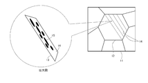
- FIG. 1 is an image diagram showing a state of precipitation of precipitates in a high-strength steel sheet as a material for the steel sheet according to the present embodiment.
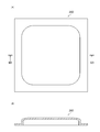
- FIG. 2A is a plan view of the parts used for the dent resistance evaluation.
- FIG. 2B is a cross-sectional view taken along the line IIB-IIB of FIG. 2A.
- FIG. 3 is a side view of a test device for measuring the dent resistance of a part and a cross-sectional view of the part, and the part is shown a cross section along the line IIB-IIB of FIG. 2 (A).
- FIG. 4 is a graph showing the relationship between the index and the dent depth of each component.
- the body member includes a panel.
- the panel is an integrally molded product.
- the panel is, for example, an exterior member of an automobile. Examples of the panel include a hood outer panel, a quarter panel such as a fender panel, a door outer panel, and a roof panel.
- Such a panel is formed by cutting a cold-rolled steel sheet, press-molding it, painting it, and then performing baking finish (baking hardening treatment) after painting.
- baking hardening treatment In seizure hardening, intrusive elements (mainly carbon) move and adhere to transitions (line defects that are the elementary process of plastic deformation) that enter the steel sheet due to cold plastic working (pre-strain), which hinders the movement. , A phenomenon in which the strength increases, and is also called strain aging.
- a baking treatment is usually performed as a heat treatment after the final annealing.
- the inventor of the present application performs a tempering treatment in a temperature range corresponding to the Si (silicon) concentration of the panel material after the final annealing, and then performs a baking hardening treatment, the amount of baking hardening increases. I got the finding. By increasing the amount of baking hardening, the yield stress is improved and the dent resistance is improved. As a result of further diligent research, the inventor of the present application has applied the above-mentioned tempering treatment to a panel material having excellent appearance after molding to obtain a panel having excellent appearance after molding and excellent dent resistance. I came up with the idea.
- the above-mentioned panel can be exemplified.
- the panel is manufactured by the above-mentioned manufacturing method.
- the panel has a steel sheet containing martensite and a paint layer formed on the steel sheet.
- the steel sheet may include a plating layer on its surface, or may not have a plating layer formed on its surface.
- the “surface of the steel sheet” means the surface of the steel sheet excluding the plating layer.
- the panel may be composed of only a steel plate without a paint layer.
- the panel contains three parts. Specifically, the panel includes (i) an edge portion, (ii) an end portion, and (iii) an edge portion and a central portion as a portion other than the end portion.
- the edge portion of (i) above is a portion that is bent by hemming (HEM) processing or is fixed to other parts by welding such as spot welding.
- the end portion of (ii) is a portion located on the center side of the panel from the edge portion, and is a portion separated from a portion fixed to other parts such as hemming or welding.
- This end portion is a portion advanced from the edge portion to, for example, the center side of the panel by several mm, and is substantially unaffected by processing for fixing the panel to other parts. In this case, "substantially unaffected” means that the amount of change in characteristics due to processing for fixing the panel to other parts is within a few percent.
- the central portion of the above (iii) is visually recognized from the outside of the automobile as the exterior of the automobile.
- a portion of the central portion of the panel having a radius of curvature of 500 mm or more is referred to as a flat portion.
- the surface roughness parameter (Sa) in the flat portion of the central portion of the panel is Sa ⁇ 0.500 ⁇ m>
- the surface roughness parameter Sa in the flat portion of the central portion of the panel is 0 ⁇ Sa ⁇ 0.500 ⁇ m.
- the flat portion in this case means a flat portion of the entire panel including the paint layer.
- the surface roughness parameter refers to, for example, the arithmetic mean height of the height from the average surface (the surface having zero height) on the surface of the 3 mm square test piece on the flat portion of the panel.
- the surface roughness parameter Sa in order to evaluate the surface roughness parameter Sa, first, the surface texture of the flat portion of the panel 3 mm square is measured with a laser microscope. Next, the measurement surface obtained by measurement is passed through a low-pass filter ( ⁇ s) defined by JIS B0601: 2013 to remove wavelength components of 0.8 mm or less from the measurement surface. Then, the surface roughness parameter (Sa) defined by ISO25178 is evaluated for the measurement surface smoothed by the low-pass filter ( ⁇ s). If the surface roughness parameter Sa is larger than 0.500 ⁇ m, the unevenness of the surface of the panel becomes large regardless of the presence or absence of the paint layer, and the appearance of the panel after molding is deteriorated.
- ⁇ s low-pass filter
- the measurement error in the laser microscope is obtained by acquiring the surface roughness parameter Sa based on the smoothed measurement surface by removing the wavelength component of 0.8 mm or less from the measurement surface.
- the true value of the surface roughness parameter Sa can be detected accurately by removing errors due to the measurement accuracy of the above, errors due to dust attached during the measurement, errors due to scratches attached when the test piece is prepared, and the like).
- control factor (requirement of metal structure) of the steel sheet for realizing the above surface roughness parameter Sa will be described below.
- the depth range from the surface to t / 4 in the plate thickness direction is divided into two regions, and the plate thickness direction (depth direction) of the steel plate starts from the surface. ),
- the depth range ending at the depth position of 20 ⁇ m is defined as the surface layer region, and the region on the center side of the steel sheet with respect to the surface layer region is defined as the internal region.
- the surface of the steel sheet excluding the plating layer is defined as the starting point of the surface layer region.
- the occurrence of surface irregularities during molding is caused by non-uniform deformation during molding due to non-uniform strength of the steel sheet in the micro region.
- the influence of the metal structure in the surface layer region which is in the range of 0 to 20 ⁇ m in the plate thickness direction from the surface (range from the surface to the position of 20 ⁇ m in the plate thickness direction from the surface), is large. Do you get it. Therefore, in the steel sheet according to the present embodiment, the metal structure of the surface layer region is controlled as follows, for example.
- ferrite is the main phase
- the volume fraction of martensite is 0.01 to 15.0%
- the volume fraction of martensite is higher than the volume fraction of martensite in the internal region. Small is preferable.
- the volume fraction of ferrite, which is the main phase is preferably in the range of 50% or more. Further, the volume fraction of martensite in the metal structure of the surface layer region is preferably smaller than the volume fraction of martensite in the internal region.
- the volume fraction of martensite in the surface layer region can be obtained by the following method.
- a sample for observing the metallographic structure (microstructure) (generally, the size is 20 mm in the rolling direction x 20 mm in the width direction x the thickness of the steel sheet) is collected from the flat portion of the obtained steel sheet, and is used from the surface layer using an optical microscope.
- the plate thickness cross section in the direction perpendicular to the rolling direction is polished as an observation surface and etched with a repeller reagent.
- the "microstructure” is classified from the optical micrographs etched with the Repeller reagent at a magnification of 500 times.
- bainite is black
- martensite including tempered martensite
- ferrite is gray. Since each structure is observed in different colors, martensite and other hard materials are observed.
- the organization can be easily identified. 10 fields of view were observed at a magnification of 500 times from the surface layer of the steel plate etched with the repeller reagent at a magnification of 500 times, and a region portion of 20 ⁇ m from the surface layer of the steel plate in the microstructure photograph was specified.
- Image analysis is performed using image analysis software to determine the area ratio of martensite.
- the maximum brightness value Lmax and the minimum brightness value Lmin of an image are acquired from an image, and a portion having pixels having a brightness of Lmax-0.3 (Lmax-Lmin) to Lmax is defined as a white region from Lmin.
- the area ratio of the martensite which is a white region, is calculated by setting the portion having a pixel of Lmin + 0.3 (Lmax ⁇ Lmin) as a black region and the other portion as a gray region.
- Image analysis is performed on a total of 10 visual fields in the same manner as described above to measure the area ratio of martensite, and these are averaged to calculate the volume fraction of martensite in the surface layer region.
- the average crystal grain size of martensite is 0.01 to 4.0 ⁇ m.
- the average crystal grain size of martensite in the surface layer region can be determined by the following method. In the same manner as above, 10 fields of view were observed from the surface layer of the steel sheet etched with the repeller reagent at a magnification of 500 times at a 1/4 thickness position, and a region of 20 ⁇ m ⁇ 200 ⁇ m was selected from the surface layer of the steel sheet in the microstructure photograph. Image analysis is performed in the same manner as above using the image analysis software of "Photoshop CS5" manufactured by Japan, and the area occupied by the martensite and the number of particles of the martensite are calculated respectively. The average area per particle of martensite is calculated by adding them up and dividing the area occupied by martensite by the number of particles of martensite. From this area and the number of particles, the diameter equivalent to a circle is calculated and used as the average crystal grain size of martensite.
- the metal structure other than ferrite and martensite is a hard structure (residual structure), and is, for example, one or more of pearlite, retained austenite, and bainite. From the viewpoint of improving the strength, it is preferable to use one or more kinds including bainite.
- the volume fraction of ferrite is 50% or more
- the volume fraction of martensite is 0.01 to 15.0%
- the volume fraction of the residual structure is 0 to 49. It is preferably .99% and the total tissue is 100%.
- the total volume fraction of ferrite and the second phase volume fraction is preferably 50.01% or more, preferably 65.0% or more, and preferably 85% or more. More preferred.
- the volume fraction of the residual tissue is preferably 35% or less, more preferably 15% or less.
- the metal structure of the internal region does not substantially affect the surface roughness parameter Sa, but preferably has the following structure requirements. That is, in the steel sheet according to the present embodiment, after controlling the metal structure of the surface layer region as described above, a position of more than 20 ⁇ m in the plate thickness direction from the surface to a position of 1/4 of the plate thickness in the plate thickness direction from the surface ( When the plate thickness is t: It is preferable that the metal structure of the internal region in the range up to t / 4) has the following structure requirements.
- ferrite is the main phase and the volume fraction of martensite is 2.0 to 25.0%.
- the volume fraction of ferrite, which is the main phase, is preferably in the range of 50% or more.
- the volume fraction of ferrite is 50% or more
- the volume fraction of martensite is 2.0 to 25.0%
- the volume fraction of the residual structure is 0 to 48. It is preferably 0.0% and the total tissue is 100%.
- the total volume fraction of ferrite and the second phase volume fraction is preferably 52.0% or more, preferably 75.0% or more, and preferably 90% or more. More preferred.
- the volume fraction of the remaining tissue is preferably 25% or less, more preferably 10% or less.
- the average crystal grain size of martensite is 1.0 ⁇ m or more and 5.0 ⁇ m or less, and larger than the average crystal grain size of martensite in the surface layer structure.
- the internal region is preferably in the range of more than 20 ⁇ m to 100 ⁇ m from the surface in the plate thickness direction.
- the first heat treatment described later has a number density of 15 precipitates / ⁇ m 2 or more having a major axis of 0.05 ⁇ m or more and 1.00 ⁇ m or less and an aspect ratio of 1: 3 or more.
- the aspect ratio refers to the ratio of the longest diameter (major diameter) of the precipitate to the longest diameter (minor diameter) of the precipitates orthogonal to the longest diameter (major diameter).
- the precipitate is not particularly limited as long as it satisfies the above requirements for major axis and aspect ratio, and examples thereof include carbides.
- the precipitate may contain or consist of iron carbide.
- the cell formation of dislocations caused by the entanglement of dislocations is suppressed, which is caused by carbon or the like diffused during baking hardening.
- the amount of dislocations that stick to the surface can be increased, and as a result, the amount of baking hardening can be significantly increased.
- the size of the dislocation cells generated in martensite is about several tens of nm or more and several hundred nm or less.
- the size of the precipitate is required to be the same. If the major axis is less than 0.05 ⁇ m, the formation of dislocation cell formation cannot be suppressed. Therefore, the major axis of the precipitate is preferably 0.05 ⁇ m or more. More preferably, it is 0.10 ⁇ m or more. On the other hand, if the major axis is larger than 1.00 ⁇ m, the precipitate becomes coarse and the amount of solid solution carbon is greatly reduced, and the amount of baking hardening is reduced. Therefore, the major axis of the precipitate is preferably 1.00 ⁇ m or less. More preferably, it is 0.80 ⁇ m or less.
- the shape of the precipitate is preferably needle-shaped rather than spherical, and the aspect ratio is preferably 1: 3 or more. If the aspect ratio is less than 1: 3, the shape of the precipitate is considered to be spherical, and the formation of dislocation cells cannot be suppressed. Therefore, the aspect ratio is set to 1: 3 or more. More preferably, it is 1: 5 or more.
- the precipitation location of the precipitate is preferably in the lath. This is because the place where the dislocation cells are most easily formed is in the lath, and the dislocation cells are hardly seen between the laths.
- the lath refers to a tissue formed in the former austenite grain boundaries by martensitic transformation.
- FIG. 1 is an image diagram showing a precipitation state of precipitates in a high-strength steel sheet as a material for the steel sheet according to the present embodiment. Referring to FIG. 1, in the lath structure 13 generated in the former austenite grain boundaries 12 during microsegregation of Si having a uniform structure 11, needle-like precipitates are uniformly formed on the entire surface of the lath 14 rather than between the lath 14.
- the number density of the precipitates 15 is preferably 15 pieces / ⁇ m 2 or more, more preferably 20 pieces / ⁇ m 2 or more, still more preferably 30 pieces / ⁇ m 2 or more, and more preferably 40 pieces / ⁇ m. 2 or more.
- the morphology and the number density of the precipitate 15 are determined by observation with an electron microscope, and are measured by, for example, TEM (transmission electron microscope) observation. Specifically, a thin film sample is cut out from the inner region of the steel sheet and observed in a bright field. 1 ⁇ m 2 is cut out at an appropriate magnification of 10,000 to 100,000 times, and the precipitates 15 having a major axis of 0.05 ⁇ m or more and 1 ⁇ m or less and an aspect ratio of 1: 3 or more are counted. This work is performed in five or more continuous fields of view, and the average thereof is defined as the number density.
- TEM transmission electron microscope
- the ratio YS 1 / YS 2 between the yield stress YS 1 measured with the tensile test piece cut out from the flat portion and the yield stress YS 2 measured with the tensile test piece cut out from the edge of the panel is 0.90 to 1. .10>
- the ratio YS 1 / YS 2 of the yield stress YS 1 and the yield stress YS 2 is 0.90 to 1.10, the flat portion and the end portion of the panel are evenly strained. It can be seen that the seizure hardening during coating baking occurs evenly over the entire steel sheet including the flat portion and the end portion.
- the yield stress YS 1 can be obtained by a tensile test performed in accordance with JIS Z 2241 using a JIS No. 5 test piece obtained by cutting out a flat portion of a panel in a direction perpendicular to the rolling direction.
- the yield stress YS 2 can be obtained by a tensile test performed in accordance with JIS Z 2241 using a JIS No. 5 test piece obtained by cutting out the end of the panel in the direction perpendicular to the rolling direction.
- the ratio YS 1 / TS 1 of the yield stress YS 1 and the tensile strength TS 1 in the tensile test piece cut out from the flat portion of the panel is preferably 0.85 or more.
- the tensile strength TS 1 can be obtained by a tensile test performed in accordance with JIS Z 2241 using a JIS No. 5 test piece obtained by cutting out a flat portion of a panel in a direction perpendicular to the rolling direction.
- the hardness of the flat portion of the panel is preferably 133 to 300 HV. When the Vickers hardness is in this range, it can be estimated that the tensile strength of the panel is 400 to 900 MPa. Hardness was measured by a Micro Vickers hardness tester in accordance with JIS Z2244: 2009. Measurements were carried out when the test force was 4.9 N at any 5 points at a depth of 1/4 from the surface in the cross section of the flat portion of the panel. The average Vickers hardness obtained was taken as the hardness of the flat portion of the panel.
- Plate thickness of flat part 0.20 mm to 0.60 mm
- the plate thickness of the flat portion of the panel is 0.20 mm to 0.60 mm. If this plate thickness is less than the above lower limit, the panel becomes too thin and it is difficult to secure sufficient dent resistance. On the other hand, if the above-mentioned plate thickness exceeds the above-mentioned upper limit, the weight of the panel is heavy and it is difficult to obtain an evaluation as a lightweight panel.
- the steel plate is a two-phase steel plate
- the steel sheet is preferably a high-strength steel sheet. Further, this steel sheet is preferably a dual phase steel sheet.
- the two-phase steel sheet contains ferrite as a soft structure and martensite as a hard structure, and has high strength and excellent workability during panel forming.
- martensite and ferrite are distributed in a mosaic pattern, and a hard part that has been metamorphosed and a soft part that has not been metamorphosed coexist.
- deformation due to cold plastic working (press forming) mainly occurs in ferrite, which has a soft structure.
- the high-strength steel plate may contain at least ferrite and martensite, and steel other than DP steel may be used.
- the tensile strength of the panel is preferably 400 to 900 MPa.
- the tensile strength of the panel is less than the above lower limit, it is difficult to achieve thinning of the panel while ensuring the strength of the panel.
- the tensile strength of the panel exceeds the above upper limit, the workability of the panel is lowered.
- the steel sheet according to this embodiment may have a plating layer on its surface. Having a plating layer on the surface is preferable because the corrosion resistance is improved.
- the applicable plating is not particularly limited, but is hot-dip galvanizing, alloyed hot-dip galvanizing, electrozinc plating, Zn—Ni plating (electrical alloy zinc plating), Sn plating, Al—Si plating, alloyed electrozinc plating, Examples thereof include hot-dip zinc-aluminum alloy plating, hot-dip zinc-aluminum-magnesium alloy plating, hot-dip zinc-aluminum-magnesium alloy-Si plated steel plate, and zinc-deposited Al plating.
- a paint layer is formed on the surface of the steel sheet according to the present embodiment.
- the paint layer is the part of the panel that is directly visible.
- the coating layer is formed on the plating layer.
- the thickness of the paint is about 100 ⁇ m.
- the paint layer in the automobile panel includes an electrodeposition paint layer, an intermediate paint layer, a base coat layer, and a clear coat layer in this order from the steel plate side.
- the thickness of the electrodeposition coating layer is, for example, 15 to 20 ⁇ m.
- the thickness of the intermediate coating layer is, for example, 25 to 35 ⁇ m.
- the thickness of the base coat layer is 10 to 15 ⁇ m.
- the thickness of the clear coat layer is 30 to 40 ⁇ m.
- the chemical composition is mass%, C: 0.020% or more, 0.145% or less, Si: 0.010% or more, 3.000% or less, Mn: 0.45% or more, 2.25% or less, P: 0.030% or less, S: 0.020% or less, sol.
- the balance consists of Fe and impurities.
- the impurity is a component that is mixed due to various factors in the manufacturing process, including raw materials such as ore and scrap, when the steel sheet is industrially manufactured, and is used in the steel sheet according to the present embodiment. On the other hand, it means a component that is not intentionally added.
- Si 0.010% to 3.000%
- Si is an element necessary for finely and a large amount of precipitates such as iron carbides for suppressing dislocation cells. If the Si content is less than 0.500%, even if the segregation has a uniform structure, sufficient effects cannot be obtained, coarse precipitates are generated, and the formation of dislocation cells cannot be suppressed. Therefore, the Si content is preferably 0.010% or more, more preferably 0.050% or more. On the other hand, if the Si content exceeds 3.000%, the effect of precipitating a large amount of precipitates in a fine manner is saturated, which unnecessarily increases the cost and deteriorates the surface texture. Therefore, the Si content is preferably 3.000% or less, preferably 2.000% or less.
- the panel according to the present embodiment can obtain the effect as long as it has the above-mentioned characteristics regardless of the manufacturing method.
- the following method is preferable because it can be stably produced.
- a high-strength steel sheet as a material for a steel sheet having an excellent surface appearance due to small surface irregularities can be manufactured by the following manufacturing method.
- the high-strength steel sheet as a material for the steel sheet constituting the panel according to the present embodiment can be manufactured by a manufacturing method including the following steps (ii) to (ivi).
- I-ii) A hot rolling step of hot rolling a steel piece at 950 ° C. or lower to obtain a hot-rolled steel sheet.
- (I-iii) A stress applying step of applying stress to a hot-rolled steel sheet after a hot rolling step so that ⁇ s, which is a residual stress on the surface, has an absolute value of 150 MPa to 450 MPa.
- (I-iv) A cold-rolling step of obtaining a cold-rolled steel sheet by cold-rolling the hot-rolled steel sheet after the stress-applying step with an RCR of 70 to 90%, which is a cumulative reduction ratio.
- (Iv) After heating the cold-rolled steel sheet so that the average heating rate from 300 ° C. to the soaking temperature T1 ° C. satisfying the following equation (1) is 1.5 to 10.0 ° C./sec.
- a plating step of forming a plating layer on the surface may be provided after the cooling step.
- the residual stress ⁇ s on the surface of the hot-rolled steel sheet is set to 150 MPa to 450 MPa by rubbing the surface of the steel sheet with a brush.
- the brush used for applying stress is a brush used for polishing and grinding, and a brush of Hotani Co., Ltd. model number: M-33 can be exemplified.
- the brush has, for example, a structure in which a large number of hard bristles are provided on the outer peripheral surface of a cylindrical brush body.
- the brush is rotated so as to face the steel sheet traveling direction at a rotation speed of 1200 rpm (so that the rotation axis of the brush body is parallel to the width direction of the hot-rolled steel sheet).
- the residual stress ⁇ s can be changed by changing the contact pressure of the brush with the hot-rolled steel sheet.
- the application of the residual stress ⁇ s to the hot-rolled steel sheet by the brush is not for changing the plate thickness of the hot-rolled steel sheet, and the plate thickness of the hot-rolled steel sheet is maintained before and after the stress application step.
- the residual stress ⁇ s can be applied to the surface layer region by rubbing the surface of the hot-rolled steel sheet without changing the plate thickness of the hot-rolled steel sheet.
- the residual stress applied in the stress applying step of the present invention is generated.
- the high-strength steel plate after final annealing is heat-treated before and after cold plastic working.
- This method (Ii-i) A first heat treatment step in which a high-strength steel plate is subjected to a heat treatment held at a temperature T11 satisfying the following formula (2) for 60 to 900 seconds.
- the temperature T11 of the high-strength steel sheet is preferably set within the range of the above-mentioned formula (2).
- the temperature T11 in the first heat treatment step is at least the above lower limit, the effect that the major axis of the precipitate is 0.05 ⁇ m or more can be obtained. Further, when the temperature T11 is not more than the above upper limit, the effect that the number density is high and the major axis of the precipitate is 1.00 ⁇ m or less can be obtained.
- the high-strength steel plate is preferably held at a constant temperature T11 within the range of the above formula (2) for 60 to 900 seconds.
- the holding time of the temperature T11 in the first heat treatment step is equal to or longer than the above lower limit, the effect of stably precipitating iron carbide can be obtained. Further, when the holding time of the temperature T11 is not more than the above upper limit, the number density of the precipitates can be increased, and the effect that the major axis of the precipitates is 1.00 ⁇ m or less can be obtained.
- the high-strength steel plate subjected to the first heat treatment is formed into a blank by blanking processing which is cut to a predetermined size.
- the first heat treatment may be performed after the high-strength steel plate is formed into a blank.
- the blank is cold plastically worked to form a steel member before it is baked. Specifically, the blank is subjected to foam forming as cold plastic working to form a steel member before baking finish.
- the shape of the steel member corresponds to the shape of the panel.
- pre-strain is applied to the entire blank to make a steel member.
- the amount of strain applied by foam molding is, for example, about 2%.
- the amount of baking hardening can be sufficiently increased by appropriately designing the molding conditions such as the operating amount of the punch in cold plastic working and the mold and applying a prestrain of about 2%.
- the steel member is painted.
- This coating includes, for example, three types of coating: electrodeposition coating, intermediate coating, and top coating (base and clear coating).
- Water-based paint or solvent paint is used for painting.
- the electrodeposition coating process the entire surface of the steel member is electrodeposited with the steel member submerged in the electrodeposition tank in which the paint is stored.
- the intermediate coating step the intermediate coating is applied to the entire surface of the steel member by spraying the paint from the spray nozzle onto the steel member manually by a coating robot or a worker.
- the top coat coating step the paint is sprayed from the spray nozzle onto the steel member by a painting robot or a worker, so that the top coat is applied to the entire surface of the steel member.
- the surface of the steel member is composed of a coating film having a thickness of about 100 ⁇ m.
- the above-mentioned coating step includes a second heat treatment step.
- the second heat treatment is a baking and drying treatment for baking the coating film on the steel member, and is a treatment for baking and hardening the steel member.
- the second heat treatment step may be performed after the electrodeposition coating and before the intermediate coating in the coating process, or may be performed between the intermediate coating and the intermediate coating which are performed a plurality of times. It may be performed after the intermediate coating and before the top coating, between the top coating and the top coating which are performed multiple times, or after the top coating. ..
- the temperature T12 of the steel member in the second heat treatment step is preferably set in the range of 80 ° C. to 200 ° C.
- the temperature T12 in the second heat treatment step is equal to or higher than the above lower limit, the paint can be reliably baked on the steel member, and the steel member can be more reliably cured. Further, if the temperature T12 exceeds the above upper limit, the cost of the panel manufacturing process is increased. Therefore, the upper limit of the holding temperature is preferably 200 ° C. or lower.
- the holding time of the temperature T12 in the second heat treatment is preferably set in the range of 300 to 1800 seconds as described above.
- the holding time in the second heat treatment step is equal to or longer than the above lower limit, the paint can be reliably baked on the steel member, and the steel member can be more reliably cured. Further, if the holding time exceeds 1800 seconds, the cost of the panel manufacturing process is increased. Therefore, the holding time is preferably 1800 seconds or less.
- the steel member is continuously held at a constant temperature T12 within the above temperature range for 300 to 1800 seconds.
- the holding time of the temperature T12 in the second heat treatment step is equal to or longer than the above lower limit, the effect that the paint is baked more reliably can be obtained. Further, when the holding time of the temperature T12 exceeds the above upper limit, the manufacturing cost of the panel increases. Therefore, the holding time of T12 is preferably 1800 seconds or less.
- the panel of the present embodiment is completed by going through the painting process including the above second heat treatment step.
- the high-strength steel plate as the material of the panel has increased uniformity by the first heat treatment step such as tempering treatment, and the blank is uniformly strained during cold plastic working.
- the amount of baking hardening in the second heat treatment as the baking hardening treatment can be further increased.
- the surface roughness parameter (Sa) in the flat portion of the central portion is Sa ⁇ 0.500 ⁇ m.
- the unevenness of the panel surface can be reduced.
- the martensite lath there are 15 precipitates / ⁇ m 2 or more having a major axis of 0.05 ⁇ m to 1.00 ⁇ m and an aspect ratio of 3 or more.
- the amount of dislocations that adhere due to carbon or the like diffused during baking hardening can be increased, and as a result, the baking hardening amount in the second heat treatment step can be significantly increased.
- YS 1 / YS 2 in the tensile test piece cut out from the flat portion is 0.90 to 1.10.
- strain is evenly applied to the entire flat portion and the end portion of the panel, and the entire steel plate at the flat portion and the end portion is evenly baked and hardened at the time of coating baking.
- the surface roughness parameter Sa the number density of precipitates, and YS 1 / YS 2 , the panel, especially the automobile exterior panel, can be used in most of the practically used plate thickness range. Both excellent surface texture and excellent dent resistance can be realized.
- the condition that the number density of precipitates in the lath is 15 pieces / ⁇ m 2 or more has been conceived.
- the condition that YS 1 / YS 2 is 0.90 to 1.10 has been conceived.
- the conditions in the examples are one condition example adopted for confirming the feasibility and effect of the present invention, and the present invention is not limited to this one condition example.
- the present invention can adopt various conditions as long as the gist of the present invention is not deviated and the object of the present invention is achieved.
- the rolling reduction difference (return-outward) between the two passes is set to 10%, and after rough rolling, it is held for 7 seconds until finish rolling, and the subsequent finish rolling process is performed on four consecutive rolling stands.
- the finish rolling process was performed in which the rolling reduction of the first stand was 20%.
- the coil was rewound to apply stress to the hot-rolled steel sheet.
- a portable X-ray residual stress measuring device was used to measure the surface residual stress online, and the contact pressure of the brush with respect to the steel plate surface was changed so as to obtain the residual stress ⁇ s shown in Table 2.
- the model number M-33 of Hotani Co., Ltd. was used.
- the brush As a method of moving the brush at the time of applying stress, the brush was rotated at a rotation speed of 1200 rpm so as to face the direction of travel of the steel sheet. Then, cold rolling was carried out at the reduction rate (cumulative reduction rate R CR ) shown in Table 2 to obtain steel sheets A1 to A2, B1 to B3, C1 to C2, D1 to D2 and E1 to E4.
- R CR cumulative reduction rate
- annealing was performed under the conditions shown in Table 3, cooled to a temperature range of 550 to 650 ° C. at the cooling rate shown in Table 3, and then cooled to the temperature shown in Table 3.
- some steel sheets were plated in various ways to form a plating layer on the surface.
- CR indicates no plating
- GI indicates hot-dip galvanizing
- GA indicates alloyed hot-dip galvanizing
- EG indicates electroplating
- Zn-Al-Mg indicates plating containing these elements.
- the first heat treatment was performed on the steel sheets A1 to A2, B1 to B3, C1 to C2, D1 to D2, and E1 to E4, which are high-strength steel sheets (cold-rolled steel sheets).
- the temperature of the high-strength steel sheet in the first heat treatment and the holding time of this temperature are shown in Table 4.
- the high-strength steel sheet subjected to the first heat treatment was subjected to cold plastic working as shown in Table 4 to form a cold-rolled steel sheet into a panel shape. As shown in FIGS.
- the panel was a panel 200 formed from a 400 mm square steel plate into a hogback shape having a ridgeline R of a flat portion in the central portion of 1200 mm.
- FIG. 2A is a plan view of the component 200 used for the dent resistance evaluation.
- FIG. 2B is a cross-sectional view taken along the line IIB-IIB of FIG. 2A.
- a second heat treatment (baking and curing) was performed on the parts molded into the shape of the panel to produce the parts to be the panels.
- the part numbers are as shown in Table 4.
- the temperature of the part in the second heat treatment and the holding time of this temperature are shown in Table 4.
- the metallographic structure of the surface layer area and the internal area was observed.
- the density of the number of precipitates having a major axis of 0.05 ⁇ m to 1.00 ⁇ m and an aspect ratio of 3 or more was measured in the martensite lath in the inner region. The results are shown in Table 5.
- the volume fraction of martensite in the surface layer region was determined by the following method.
- a sample for observing the metallographic structure (microstructure) (20 mm in the rolling direction x 20 mm in the width direction x thickness of the steel sheet) was collected from the flat portion of the steel sheet of the obtained part, and the sheet was coated from the surface layer of the steel sheet using an optical microscope.
- the metallographic structure was observed at a thickness of 1/4, and the area ratio of maltensite from the surface of the steel sheet (the surface excluding the plating layer when plating was present) to 20 ⁇ m was calculated.
- the plate thickness cross section in the direction perpendicular to rolling was polished as an observation surface and etched with a repeller reagent.
- the "microstructure" was classified from the optical micrographs etched with the Repeller reagent at a magnification of 500 times. 10 fields of view were observed at a magnification of 500 times from the surface layer of the steel plate etched with the repeller reagent at a magnification of 500 times, and a region portion of 20 ⁇ m from the surface layer of the steel plate in the microstructure photograph was specified. Image analysis was performed using image analysis software to determine the area ratio of martensite. Image analysis was performed on a total of 10 visual fields in the same manner as described above to measure the area ratio of martensite, and these were averaged to calculate the volume fraction of martensite in the surface layer region.
- the average crystal grain size of martensite in the surface layer region was determined by the following method. In the same way as the volume fraction of martensite was obtained, 10 fields were observed at a magnification of 500 times from the surface layer of the steel sheet etched with the repeller reagent at a 1/4 thickness position, and 20 ⁇ m ⁇ 20 ⁇ m from the surface layer of the steel sheet in the microstructure photograph. A region of 200 ⁇ m was selected, and image analysis was performed using image analysis software of “Photoshop CS5” manufactured by Adobe, and the area occupied by martensite and the number of particles of martensite were calculated respectively. The average area per particle of martensite was calculated by adding them up and dividing the area occupied by martensite by the number of particles of martensite. From this area and the number of particles, the diameter equivalent to a circle was calculated and used as the average crystal grain size of martensite.
- a steel plate etched with a repeller reagent was used, and the range from the surface of the sample to the position of more than 20 ⁇ m in the plate thickness direction to 1/4 of the plate thickness was set. It was obtained by selecting and analyzing by the same method as the surface area.
- the number of precipitates density refers to the density of precipitates having a major axis of 0.05 ⁇ m or more and 1.00 ⁇ m or less and an aspect ratio of 1: 3 or more.
- the morphology and number density of the precipitates were determined by observation with an electron microscope, and in this example, they were measured by TEM (Transmission Electron Microscope) observation. Specifically, with respect to the internal region, a thin film sample was cut out from the region from the 3/8 position to the 1/4 position of the thickness of the flat portion of the steel plate with reference to the surface of the flat portion of the steel sheet.
- this thin film sample is observed in a bright field, 1 ⁇ m 2 is cut out at an appropriate magnification of 10,000 to 100,000 times, and precipitates having a major axis of 0.05 ⁇ m or more and 1 ⁇ m or less and an aspect ratio of 1: 3 or more are counted. I asked. This work was performed in five or more continuous fields of view, and the average was taken as the number density.
- the yield stress ratio YS 1 / YS 2 between the flat part and the end the ratio YS 1 / TS 1 between the yield stress and the tensile strength, the tensile strength, the hardness of the flat part, and the panel.
- the plate thickness and was measured The results are shown in Table 6.
- Table 6 also shows the steel types of the parts. DP steel indicates Dual Phase steel and TRIP steel indicates Transformation Induced Plasticity steel.
- the yield stress YS 1 is obtained by a tensile test performed in accordance with JIS Z 2241 using a JIS No. 5 test piece obtained by cutting a flat portion in a direction perpendicular to the rolling direction. I asked.
- the yield stress YS 2 was determined by a tensile test performed in accordance with JIS Z 2241 using a JIS No. 5 test piece whose end was cut out in a direction perpendicular to the rolling direction.
- the tensile strength TS 1 is obtained by a tensile test conducted in accordance with JIS Z 2241 using a JIS No. 5 test piece obtained by cutting out a flat portion in a direction perpendicular to the rolling direction. I asked.
- the hardness of the flat part was measured by a Micro Vickers hardness tester in accordance with JIS Z2244: 2009. Measurements were carried out when the test force was 4.9 N at any 5 points at a depth of 1/4 from the surface of the cross section of the steel sheet. The average of the obtained Vickers hardness was taken as the hardness of the flat part of the part.
- FIG. 3 is a side view of the test apparatus 20 for measuring the dent resistance of the component 200 and a cross-sectional view of the component 200.
- the test apparatus 20 has a load unit 220.
- the load unit 220 includes two columns 221a and 221b. These two columns 221a and 221b are connected by a beam-shaped connecting portion 222.
- an indenter rod holding portion 223 In the center of the connecting portion 222, an indenter rod holding portion 223 that enables the indenter rod 224 to operate up and down is provided.
- the indenter rod 224 is provided with a held portion 225 supported on the indenter rod holding portion 223.
- a hemispherical indenter 226 made of steel and having a radius of 25 mm provided at the tip of the indenter rod 224 descends downward.
- the tip of the indenter 226 comes into contact with the center of the upper surface at the substantially center of the convex portion in the central portion of the test panel 200 mounted on the pedestal 211, and a load controlled to a predetermined constant value is applied to the center of the upper surface.
- a dent mark is formed on the test panel 200.
- the load applied to the test panel 200 is constant. If the test panel 200 has good dent resistance, the dent marks formed will be shallow.
- the dent resistance of the test panel 200 was evaluated by measuring the dent depth when a load of 20 kgf was applied to the test panel 200 by the indenter 226.
- a spherical indenter 226 having a radius of 25 mm was pushed into the component with 20 kgf and held for 5 seconds.
- the dent remaining after unloading was measured with a 3-point dial gauge having a span of 40 mm and used as a dent depth (mm). Since the dent depth depends on the steel type and plate thickness of the part, the part that falls below the index S defined by the following formula is considered to have excellent dent resistance.
- the index S indicates a reference dent depth.
- Formula: S -0.0006 x TS x t 2 +0.292 TS is the tensile strength, and t is the thickness of the steel plate.
- the relationship between the index S and the dent depth of each component is shown in FIG.
- the horizontal axis of the graph of FIG. 4 shows the value of TS ⁇ t 2
- the vertical axis shows the dent depth (mm).
- the line segment shown in FIG. 4 indicates the index S (index line).
- Table 7 shows the surface roughness parameter Sa of each part and the result of the dent resistance evaluation. Parts having a surface roughness parameter Sa of 0.500 ⁇ m or less were evaluated as having less surface irregularities and excellent appearance. Further, in the dent resistance evaluation, parts having a dent depth of index S or less were evaluated as having excellent dent resistance. Further, Table 7 shows the ratio of the dent depth to the index S, and it can be seen that the smaller the ratio value, the better the dent resistance.
- the surface texture evaluation and dent resistance evaluation of the panel cleared the standard. That is, in the examples, it was demonstrated that the formation of surface irregularities after processing was suppressed, and that the dent resistance was excellent.
- the parts D1a, D2a, E1a, E2a, and E4a have a density of 40 or more precipitates in the martensite truss.
- any one or more of the surface roughness parameter Sa, the number density of precipitates in the lath of martensite, and the yield stress ratio YS 1 / YS 2 of the flat portion is out of the preferable range (comparative example).
- the non-uniform surface texture causes patterns or irregularities, or the dent resistance is poor and it is not suitable for use as an exterior panel.
- the component A2a which is a comparative example, had a bad appearance because the surface roughness parameter Sa was below the standard.
- the yield stress ratio YS 1 / YS 2 of the part B1b is out of the preferable range, the strain amount is biased in each part of the panel, and the baking hardening amount at the time of coating baking is biased.
- Dent resistance was below the standard.
- the parts B2a and B3a had a bad appearance because the surface roughness parameter Sa was below the standard.
- the dent resistance of the component C1b was below the standard for the above-mentioned reason.
- the appearance of the component C2a was poor because the surface roughness parameter Sa was below the standard.
- the number density of the precipitates in the martensitic truss was far below the preferable range, and the dent resistance was poor because the dent resistance was not sufficiently hardened by baking.
- the appearance of the component E3a was poor because the surface roughness parameter Sa was below the standard.
- the present invention can be widely applied as a panel.
Abstract
L'invention concerne un panneau présentant un aspect exceptionnel après avoir été moulé à partir d'un matériau, le panneau présentant également une résistance aux bosses exceptionnelle. Un panneau présente une tôle d'acier contenant de la martensite, le panneau étant tel qu'un paramètre de rugosité de surface (Sa) d'une section plate d'une partie côté centre du panneau satisfait à Sa ≤ 0,500 μm. Dans le panneau, le nombre de dépôts présentant un diamètre de 0,05 à 1,00 µm de long et un rapport d'aspect supérieur ou égal à 3 à l'intérieur d'une latte de la martensite est de 15 par μm2. Le rapport YS1/YS2 entre la limite d'élasticité YS1 mesurée dans un morceau soumis à un test de traction qui a été découpé dans la section plate de la partie côté centre du panneau et la limite d'élasticité YS2 mesurée dans un morceau soumis à un test de traction qui a été découpé dans une section extrémité du panneau est de 0,90-1,10.
Priority Applications (5)
| Application Number | Priority Date | Filing Date | Title |
|---|---|---|---|
| CN202180010504.XA CN115003840B (zh) | 2020-01-24 | 2021-01-22 | 板件 |
| JP2021572821A JPWO2021149810A1 (fr) | 2020-01-24 | 2021-01-22 | |
| EP21743951.2A EP4095271A4 (fr) | 2020-01-24 | 2021-01-22 | Panneau |
| KR1020227028928A KR20220129066A (ko) | 2020-01-24 | 2021-01-22 | 패널 |
| US17/791,424 US20230050487A1 (en) | 2020-01-24 | 2021-01-22 | Panel |
Applications Claiming Priority (2)
| Application Number | Priority Date | Filing Date | Title |
|---|---|---|---|
| JP2020009753 | 2020-01-24 | ||
| JP2020-009753 | 2020-01-24 |
Publications (1)
| Publication Number | Publication Date |
|---|---|
| WO2021149810A1 true WO2021149810A1 (fr) | 2021-07-29 |
Family
ID=76991799
Family Applications (1)
| Application Number | Title | Priority Date | Filing Date |
|---|---|---|---|
| PCT/JP2021/002285 WO2021149810A1 (fr) | 2020-01-24 | 2021-01-22 | Panneau |
Country Status (6)
| Country | Link |
|---|---|
| US (1) | US20230050487A1 (fr) |
| EP (1) | EP4095271A4 (fr) |
| JP (1) | JPWO2021149810A1 (fr) |
| KR (1) | KR20220129066A (fr) |
| CN (1) | CN115003840B (fr) |
| WO (1) | WO2021149810A1 (fr) |
Citations (5)
| Publication number | Priority date | Publication date | Assignee | Title |
|---|---|---|---|---|
| JP2006118021A (ja) * | 2004-10-25 | 2006-05-11 | Sumitomo Metal Ind Ltd | 低合金鋼及びその製造方法 |
| JP2013151738A (ja) * | 2011-12-28 | 2013-08-08 | Jfe Steel Corp | 耐デント性に優れた高強度薄鋼板およびその製造方法 |
| JP2013185240A (ja) * | 2012-03-09 | 2013-09-19 | Nippon Steel & Sumitomo Metal Corp | 高張力冷延鋼板および高張力めっき鋼板ならびにそれらの製造方法 |
| JP2016156079A (ja) | 2015-02-26 | 2016-09-01 | 新日鐵住金株式会社 | フェライト系薄鋼板 |
| WO2020022481A1 (fr) * | 2018-07-27 | 2020-01-30 | 日本製鉄株式会社 | Plaque d'acier à haute résistance |
Family Cites Families (10)
| Publication number | Priority date | Publication date | Assignee | Title |
|---|---|---|---|---|
| JP4177478B2 (ja) * | 1998-04-27 | 2008-11-05 | Jfeスチール株式会社 | 成形性、パネル形状性、耐デント性に優れた冷延鋼板、溶融亜鉛めっき鋼板及びそれらの製造方法 |
| JP3643556B2 (ja) * | 2001-12-27 | 2005-04-27 | 新日本製鐵株式会社 | 強度異方性の無い高張力圧延鋼板およびその製造方法 |
| US6709535B2 (en) * | 2002-05-30 | 2004-03-23 | Kobe Steel, Ltd. | Superhigh-strength dual-phase steel sheet of excellent fatigue characteristic in a spot welded joint |
| KR20080061855A (ko) * | 2006-12-28 | 2008-07-03 | 주식회사 포스코 | 딥드로잉성이 우수한 복합조직강판 |
| KR100958019B1 (ko) * | 2009-08-31 | 2010-05-17 | 현대하이스코 주식회사 | 복합조직강판 및 이를 제조하는 방법 |
| JP5310920B2 (ja) * | 2011-12-08 | 2013-10-09 | Jfeスチール株式会社 | 耐時効性と焼付き硬化性に優れた高強度冷延鋼板 |
| EP3276021B1 (fr) * | 2015-03-27 | 2019-12-04 | JFE Steel Corporation | Tôle d'acier à haute résistance et procédé de production associé |
| RU2686715C1 (ru) * | 2015-04-08 | 2019-04-30 | Ниппон Стил Энд Сумитомо Метал Корпорейшн | Элемент из термообработанного стального листа и способ его производства |
| JP6606905B2 (ja) * | 2015-07-30 | 2019-11-20 | 日本製鉄株式会社 | 自動車の外板パネル用合金化溶融亜鉛めっき鋼板およびその製造方法 |
| WO2017131055A1 (fr) * | 2016-01-27 | 2017-08-03 | Jfeスチール株式会社 | Tôle d'acier galvanisé haute résistance à rapport d'élasticité élevé et son procédé de production |
-
2021
- 2021-01-22 KR KR1020227028928A patent/KR20220129066A/ko unknown
- 2021-01-22 JP JP2021572821A patent/JPWO2021149810A1/ja active Pending
- 2021-01-22 US US17/791,424 patent/US20230050487A1/en active Pending
- 2021-01-22 WO PCT/JP2021/002285 patent/WO2021149810A1/fr unknown
- 2021-01-22 EP EP21743951.2A patent/EP4095271A4/fr active Pending
- 2021-01-22 CN CN202180010504.XA patent/CN115003840B/zh active Active
Patent Citations (5)
| Publication number | Priority date | Publication date | Assignee | Title |
|---|---|---|---|---|
| JP2006118021A (ja) * | 2004-10-25 | 2006-05-11 | Sumitomo Metal Ind Ltd | 低合金鋼及びその製造方法 |
| JP2013151738A (ja) * | 2011-12-28 | 2013-08-08 | Jfe Steel Corp | 耐デント性に優れた高強度薄鋼板およびその製造方法 |
| JP2013185240A (ja) * | 2012-03-09 | 2013-09-19 | Nippon Steel & Sumitomo Metal Corp | 高張力冷延鋼板および高張力めっき鋼板ならびにそれらの製造方法 |
| JP2016156079A (ja) | 2015-02-26 | 2016-09-01 | 新日鐵住金株式会社 | フェライト系薄鋼板 |
| WO2020022481A1 (fr) * | 2018-07-27 | 2020-01-30 | 日本製鉄株式会社 | Plaque d'acier à haute résistance |
Non-Patent Citations (1)
| Title |
|---|
| See also references of EP4095271A4 |
Also Published As
| Publication number | Publication date |
|---|---|
| CN115003840B (zh) | 2023-04-21 |
| KR20220129066A (ko) | 2022-09-22 |
| EP4095271A1 (fr) | 2022-11-30 |
| US20230050487A1 (en) | 2023-02-16 |
| CN115003840A (zh) | 2022-09-02 |
| EP4095271A4 (fr) | 2023-01-04 |
| JPWO2021149810A1 (fr) | 2021-07-29 |
Similar Documents
| Publication | Publication Date | Title |
|---|---|---|
| KR101930186B1 (ko) | 고강도 용융 아연 도금 강판 및 그 제조 방법 | |
| KR101990717B1 (ko) | 고강도 용융 아연 도금 강판 및 그 제조 방법 | |
| KR101217921B1 (ko) | 고강도 용융 아연 도금 강판 및 그 제조 방법 | |
| EP1486574A1 (fr) | Procede pour fabriquer une feuille d'acier galvanisee a chaud de haute resistance, presentant une excellente ductilite et une grande resistance a la fatigue | |
| KR102529040B1 (ko) | 열연 강판 및 그 제조 방법 | |
| CN109844158A (zh) | 用于涂漆零件的钢基底 | |
| KR101972683B1 (ko) | 고강도 용융 아연 도금 강판 및 그 제조 방법 | |
| CN109844159A (zh) | 用于涂漆零件的钢 | |
| KR102485637B1 (ko) | 강판 및 그 제조 방법 | |
| JP6052219B2 (ja) | 成形性に優れた高強度薄鋼板およびその製造方法 | |
| JP6052220B2 (ja) | 成形性に優れた高強度冷延薄鋼板およびその製造方法 | |
| KR102562003B1 (ko) | 강판 및 그 제조 방법 | |
| JP6809651B2 (ja) | 鋼板及びその製造方法 | |
| JP7401821B2 (ja) | 外装パネルおよびそれを備える自動車 | |
| WO2021149810A1 (fr) | Panneau | |
| US11060157B2 (en) | Steel sheet, coated steel sheet, method for producing hot-rolled steel sheet, method for producing full hard cold-rolled steel sheet, method for producing steel sheet, and method for producing coated steel sheet | |
| JP7215647B1 (ja) | 高強度鋼板およびその製造方法 | |
| EP4343011A1 (fr) | Tôle d'acier allié galvanisée par trempage à chaud |
Legal Events
| Date | Code | Title | Description |
|---|---|---|---|
| 121 | Ep: the epo has been informed by wipo that ep was designated in this application |
Ref document number: 21743951 Country of ref document: EP Kind code of ref document: A1 |
|
| ENP | Entry into the national phase |
Ref document number: 2021572821 Country of ref document: JP Kind code of ref document: A |
|
| NENP | Non-entry into the national phase |
Ref country code: DE |
|
| ENP | Entry into the national phase |
Ref document number: 2021743951 Country of ref document: EP Effective date: 20220824 |