WO2021149810A1 - Panel - Google Patents
Panel Download PDFInfo
- Publication number
- WO2021149810A1 WO2021149810A1 PCT/JP2021/002285 JP2021002285W WO2021149810A1 WO 2021149810 A1 WO2021149810 A1 WO 2021149810A1 JP 2021002285 W JP2021002285 W JP 2021002285W WO 2021149810 A1 WO2021149810 A1 WO 2021149810A1
- Authority
- WO
- WIPO (PCT)
- Prior art keywords
- panel
- steel sheet
- martensite
- flat portion
- steel
- Prior art date
Links
Images


Classifications
-
- C—CHEMISTRY; METALLURGY
- C21—METALLURGY OF IRON
- C21D—MODIFYING THE PHYSICAL STRUCTURE OF FERROUS METALS; GENERAL DEVICES FOR HEAT TREATMENT OF FERROUS OR NON-FERROUS METALS OR ALLOYS; MAKING METAL MALLEABLE, e.g. BY DECARBURISATION OR TEMPERING
- C21D8/00—Modifying the physical properties by deformation combined with, or followed by, heat treatment
- C21D8/02—Modifying the physical properties by deformation combined with, or followed by, heat treatment during manufacturing of plates or strips
- C21D8/0278—Modifying the physical properties by deformation combined with, or followed by, heat treatment during manufacturing of plates or strips involving a particular surface treatment
-
- C—CHEMISTRY; METALLURGY
- C21—METALLURGY OF IRON
- C21D—MODIFYING THE PHYSICAL STRUCTURE OF FERROUS METALS; GENERAL DEVICES FOR HEAT TREATMENT OF FERROUS OR NON-FERROUS METALS OR ALLOYS; MAKING METAL MALLEABLE, e.g. BY DECARBURISATION OR TEMPERING
- C21D9/00—Heat treatment, e.g. annealing, hardening, quenching or tempering, adapted for particular articles; Furnaces therefor
- C21D9/46—Heat treatment, e.g. annealing, hardening, quenching or tempering, adapted for particular articles; Furnaces therefor for sheet metals
-
- C—CHEMISTRY; METALLURGY
- C22—METALLURGY; FERROUS OR NON-FERROUS ALLOYS; TREATMENT OF ALLOYS OR NON-FERROUS METALS
- C22C—ALLOYS
- C22C38/00—Ferrous alloys, e.g. steel alloys
-
- C—CHEMISTRY; METALLURGY
- C22—METALLURGY; FERROUS OR NON-FERROUS ALLOYS; TREATMENT OF ALLOYS OR NON-FERROUS METALS
- C22C—ALLOYS
- C22C38/00—Ferrous alloys, e.g. steel alloys
- C22C38/001—Ferrous alloys, e.g. steel alloys containing N
-
- C—CHEMISTRY; METALLURGY
- C22—METALLURGY; FERROUS OR NON-FERROUS ALLOYS; TREATMENT OF ALLOYS OR NON-FERROUS METALS
- C22C—ALLOYS
- C22C38/00—Ferrous alloys, e.g. steel alloys
- C22C38/02—Ferrous alloys, e.g. steel alloys containing silicon
-
- C—CHEMISTRY; METALLURGY
- C22—METALLURGY; FERROUS OR NON-FERROUS ALLOYS; TREATMENT OF ALLOYS OR NON-FERROUS METALS
- C22C—ALLOYS
- C22C38/00—Ferrous alloys, e.g. steel alloys
- C22C38/04—Ferrous alloys, e.g. steel alloys containing manganese
-
- C—CHEMISTRY; METALLURGY
- C22—METALLURGY; FERROUS OR NON-FERROUS ALLOYS; TREATMENT OF ALLOYS OR NON-FERROUS METALS
- C22C—ALLOYS
- C22C38/00—Ferrous alloys, e.g. steel alloys
- C22C38/06—Ferrous alloys, e.g. steel alloys containing aluminium
-
- C—CHEMISTRY; METALLURGY
- C22—METALLURGY; FERROUS OR NON-FERROUS ALLOYS; TREATMENT OF ALLOYS OR NON-FERROUS METALS
- C22C—ALLOYS
- C22C38/00—Ferrous alloys, e.g. steel alloys
- C22C38/12—Ferrous alloys, e.g. steel alloys containing tungsten, tantalum, molybdenum, vanadium, or niobium
-
- C—CHEMISTRY; METALLURGY
- C22—METALLURGY; FERROUS OR NON-FERROUS ALLOYS; TREATMENT OF ALLOYS OR NON-FERROUS METALS
- C22C—ALLOYS
- C22C38/00—Ferrous alloys, e.g. steel alloys
- C22C38/14—Ferrous alloys, e.g. steel alloys containing titanium or zirconium
-
- C—CHEMISTRY; METALLURGY
- C22—METALLURGY; FERROUS OR NON-FERROUS ALLOYS; TREATMENT OF ALLOYS OR NON-FERROUS METALS
- C22C—ALLOYS
- C22C38/00—Ferrous alloys, e.g. steel alloys
- C22C38/18—Ferrous alloys, e.g. steel alloys containing chromium
-
- C—CHEMISTRY; METALLURGY
- C22—METALLURGY; FERROUS OR NON-FERROUS ALLOYS; TREATMENT OF ALLOYS OR NON-FERROUS METALS
- C22C—ALLOYS
- C22C38/00—Ferrous alloys, e.g. steel alloys
- C22C38/18—Ferrous alloys, e.g. steel alloys containing chromium
- C22C38/40—Ferrous alloys, e.g. steel alloys containing chromium with nickel
- C22C38/58—Ferrous alloys, e.g. steel alloys containing chromium with nickel with more than 1.5% by weight of manganese
-
- G—PHYSICS
- G01—MEASURING; TESTING
- G01N—INVESTIGATING OR ANALYSING MATERIALS BY DETERMINING THEIR CHEMICAL OR PHYSICAL PROPERTIES
- G01N1/00—Sampling; Preparing specimens for investigation
- G01N1/02—Devices for withdrawing samples
- G01N1/04—Devices for withdrawing samples in the solid state, e.g. by cutting
- G01N1/06—Devices for withdrawing samples in the solid state, e.g. by cutting providing a thin slice, e.g. microtome
-
- B—PERFORMING OPERATIONS; TRANSPORTING
- B62—LAND VEHICLES FOR TRAVELLING OTHERWISE THAN ON RAILS
- B62D—MOTOR VEHICLES; TRAILERS
- B62D25/00—Superstructure or monocoque structure sub-units; Parts or details thereof not otherwise provided for
- B62D25/02—Side panels
-
- B—PERFORMING OPERATIONS; TRANSPORTING
- B62—LAND VEHICLES FOR TRAVELLING OTHERWISE THAN ON RAILS
- B62D—MOTOR VEHICLES; TRAILERS
- B62D25/00—Superstructure or monocoque structure sub-units; Parts or details thereof not otherwise provided for
- B62D25/06—Fixed roofs
-
- B—PERFORMING OPERATIONS; TRANSPORTING
- B62—LAND VEHICLES FOR TRAVELLING OTHERWISE THAN ON RAILS
- B62D—MOTOR VEHICLES; TRAILERS
- B62D25/00—Superstructure or monocoque structure sub-units; Parts or details thereof not otherwise provided for
- B62D25/08—Front or rear portions
- B62D25/10—Bonnets or lids, e.g. for trucks, tractors, busses, work vehicles
- B62D25/105—Bonnets or lids, e.g. for trucks, tractors, busses, work vehicles for motor cars
-
- C—CHEMISTRY; METALLURGY
- C21—METALLURGY OF IRON
- C21D—MODIFYING THE PHYSICAL STRUCTURE OF FERROUS METALS; GENERAL DEVICES FOR HEAT TREATMENT OF FERROUS OR NON-FERROUS METALS OR ALLOYS; MAKING METAL MALLEABLE, e.g. BY DECARBURISATION OR TEMPERING
- C21D2201/00—Treatment for obtaining particular effects
- C21D2201/02—Superplasticity
-
- C—CHEMISTRY; METALLURGY
- C21—METALLURGY OF IRON
- C21D—MODIFYING THE PHYSICAL STRUCTURE OF FERROUS METALS; GENERAL DEVICES FOR HEAT TREATMENT OF FERROUS OR NON-FERROUS METALS OR ALLOYS; MAKING METAL MALLEABLE, e.g. BY DECARBURISATION OR TEMPERING
- C21D2211/00—Microstructure comprising significant phases
- C21D2211/004—Dispersions; Precipitations
-
- C—CHEMISTRY; METALLURGY
- C21—METALLURGY OF IRON
- C21D—MODIFYING THE PHYSICAL STRUCTURE OF FERROUS METALS; GENERAL DEVICES FOR HEAT TREATMENT OF FERROUS OR NON-FERROUS METALS OR ALLOYS; MAKING METAL MALLEABLE, e.g. BY DECARBURISATION OR TEMPERING
- C21D2211/00—Microstructure comprising significant phases
- C21D2211/005—Ferrite
-
- C—CHEMISTRY; METALLURGY
- C21—METALLURGY OF IRON
- C21D—MODIFYING THE PHYSICAL STRUCTURE OF FERROUS METALS; GENERAL DEVICES FOR HEAT TREATMENT OF FERROUS OR NON-FERROUS METALS OR ALLOYS; MAKING METAL MALLEABLE, e.g. BY DECARBURISATION OR TEMPERING
- C21D2211/00—Microstructure comprising significant phases
- C21D2211/008—Martensite
Definitions
- the present invention relates to a panel.
- the modeling of automobile outer panel parts tends to become more and more complicated. If the steel sheet is made stronger and thinner in order to reduce the weight, the surface of the steel sheet is likely to have irregularities when it is formed into a complicated shape. If the surface is uneven, the appearance after molding is deteriorated.
- the outer panel is required to have an excellent appearance after molding because not only properties such as strength but also design and surface quality are important. That is, the outer panel of an automobile is required to have an appearance (surface texture) so that surface roughness and patterns do not occur after molding.
- Patent Document 1 in order to improve the surface texture after the overhanging process, from the ⁇ 001 ⁇ surface parallel to the surface of the steel sheet.
- a ferritic thin steel sheet in which the area fraction of a crystal having a crystal orientation within ⁇ 15 ° is 0.25 or less and the average particle size of the crystal is 25 ⁇ m or less is disclosed.
- Dent resistance refers to the difficulty of residual dents after removing a local load on the panel for some reason. In an actual automobile body, it occurs when the outer panel such as a door is strongly pressed with a finger or palm, or when a stepping stone hits while driving. Dent is generated by plastic deformation of the part of the panel to which the load is applied. Therefore, when the strain of the panel reaches a certain magnitude when the load is applied to the panel, the strain remains even after unloading and dent occurs. The minimum value of the load that causes a constant residual strain on the panel is called the dent load, and the larger the dent load, the better the dent resistance. Patent Document 1 does not disclose that the dent resistance is improved.
- one of the objects of the present invention is to provide a panel having an excellent appearance after being molded from a material and having excellent dent resistance.
- the gist of the present invention is the following panel.
- a panel having a steel plate containing martensite The surface roughness parameter (Sa) in the flat portion of the central portion of the panel is Sa ⁇ 0.500 ⁇ m.
- the martensite lath 15 precipitates / ⁇ m 2 or more having a major axis of 0.05 ⁇ m to 1.00 ⁇ m and an aspect ratio of 3 or more are provided.
- the ratio YS 1 / YS 2 of the yield stress YS 1 measured by the tensile test piece cut out from the flat portion and the yield stress YS 2 measured by the tensile test piece cut out from the edge of the panel is 0.90 to 0.
- the panel which is 1.10.
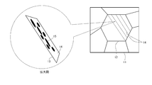
- FIG. 1 is an image diagram showing a state of precipitation of precipitates in a high-strength steel sheet as a material for the steel sheet according to the present embodiment.
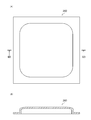
- FIG. 2A is a plan view of the parts used for the dent resistance evaluation.
- FIG. 2B is a cross-sectional view taken along the line IIB-IIB of FIG. 2A.
- FIG. 3 is a side view of a test device for measuring the dent resistance of a part and a cross-sectional view of the part, and the part is shown a cross section along the line IIB-IIB of FIG. 2 (A).
- FIG. 4 is a graph showing the relationship between the index and the dent depth of each component.
- the body member includes a panel.
- the panel is an integrally molded product.
- the panel is, for example, an exterior member of an automobile. Examples of the panel include a hood outer panel, a quarter panel such as a fender panel, a door outer panel, and a roof panel.
- Such a panel is formed by cutting a cold-rolled steel sheet, press-molding it, painting it, and then performing baking finish (baking hardening treatment) after painting.
- baking hardening treatment In seizure hardening, intrusive elements (mainly carbon) move and adhere to transitions (line defects that are the elementary process of plastic deformation) that enter the steel sheet due to cold plastic working (pre-strain), which hinders the movement. , A phenomenon in which the strength increases, and is also called strain aging.
- a baking treatment is usually performed as a heat treatment after the final annealing.
- the inventor of the present application performs a tempering treatment in a temperature range corresponding to the Si (silicon) concentration of the panel material after the final annealing, and then performs a baking hardening treatment, the amount of baking hardening increases. I got the finding. By increasing the amount of baking hardening, the yield stress is improved and the dent resistance is improved. As a result of further diligent research, the inventor of the present application has applied the above-mentioned tempering treatment to a panel material having excellent appearance after molding to obtain a panel having excellent appearance after molding and excellent dent resistance. I came up with the idea.
- the above-mentioned panel can be exemplified.
- the panel is manufactured by the above-mentioned manufacturing method.
- the panel has a steel sheet containing martensite and a paint layer formed on the steel sheet.
- the steel sheet may include a plating layer on its surface, or may not have a plating layer formed on its surface.
- the “surface of the steel sheet” means the surface of the steel sheet excluding the plating layer.
- the panel may be composed of only a steel plate without a paint layer.
- the panel contains three parts. Specifically, the panel includes (i) an edge portion, (ii) an end portion, and (iii) an edge portion and a central portion as a portion other than the end portion.
- the edge portion of (i) above is a portion that is bent by hemming (HEM) processing or is fixed to other parts by welding such as spot welding.
- the end portion of (ii) is a portion located on the center side of the panel from the edge portion, and is a portion separated from a portion fixed to other parts such as hemming or welding.
- This end portion is a portion advanced from the edge portion to, for example, the center side of the panel by several mm, and is substantially unaffected by processing for fixing the panel to other parts. In this case, "substantially unaffected” means that the amount of change in characteristics due to processing for fixing the panel to other parts is within a few percent.
- the central portion of the above (iii) is visually recognized from the outside of the automobile as the exterior of the automobile.
- a portion of the central portion of the panel having a radius of curvature of 500 mm or more is referred to as a flat portion.
- the surface roughness parameter (Sa) in the flat portion of the central portion of the panel is Sa ⁇ 0.500 ⁇ m>
- the surface roughness parameter Sa in the flat portion of the central portion of the panel is 0 ⁇ Sa ⁇ 0.500 ⁇ m.
- the flat portion in this case means a flat portion of the entire panel including the paint layer.
- the surface roughness parameter refers to, for example, the arithmetic mean height of the height from the average surface (the surface having zero height) on the surface of the 3 mm square test piece on the flat portion of the panel.
- the surface roughness parameter Sa in order to evaluate the surface roughness parameter Sa, first, the surface texture of the flat portion of the panel 3 mm square is measured with a laser microscope. Next, the measurement surface obtained by measurement is passed through a low-pass filter ( ⁇ s) defined by JIS B0601: 2013 to remove wavelength components of 0.8 mm or less from the measurement surface. Then, the surface roughness parameter (Sa) defined by ISO25178 is evaluated for the measurement surface smoothed by the low-pass filter ( ⁇ s). If the surface roughness parameter Sa is larger than 0.500 ⁇ m, the unevenness of the surface of the panel becomes large regardless of the presence or absence of the paint layer, and the appearance of the panel after molding is deteriorated.
- ⁇ s low-pass filter
- the measurement error in the laser microscope is obtained by acquiring the surface roughness parameter Sa based on the smoothed measurement surface by removing the wavelength component of 0.8 mm or less from the measurement surface.
- the true value of the surface roughness parameter Sa can be detected accurately by removing errors due to the measurement accuracy of the above, errors due to dust attached during the measurement, errors due to scratches attached when the test piece is prepared, and the like).
- control factor (requirement of metal structure) of the steel sheet for realizing the above surface roughness parameter Sa will be described below.
- the depth range from the surface to t / 4 in the plate thickness direction is divided into two regions, and the plate thickness direction (depth direction) of the steel plate starts from the surface. ),
- the depth range ending at the depth position of 20 ⁇ m is defined as the surface layer region, and the region on the center side of the steel sheet with respect to the surface layer region is defined as the internal region.
- the surface of the steel sheet excluding the plating layer is defined as the starting point of the surface layer region.
- the occurrence of surface irregularities during molding is caused by non-uniform deformation during molding due to non-uniform strength of the steel sheet in the micro region.
- the influence of the metal structure in the surface layer region which is in the range of 0 to 20 ⁇ m in the plate thickness direction from the surface (range from the surface to the position of 20 ⁇ m in the plate thickness direction from the surface), is large. Do you get it. Therefore, in the steel sheet according to the present embodiment, the metal structure of the surface layer region is controlled as follows, for example.
- ferrite is the main phase
- the volume fraction of martensite is 0.01 to 15.0%
- the volume fraction of martensite is higher than the volume fraction of martensite in the internal region. Small is preferable.
- the volume fraction of ferrite, which is the main phase is preferably in the range of 50% or more. Further, the volume fraction of martensite in the metal structure of the surface layer region is preferably smaller than the volume fraction of martensite in the internal region.
- the volume fraction of martensite in the surface layer region can be obtained by the following method.
- a sample for observing the metallographic structure (microstructure) (generally, the size is 20 mm in the rolling direction x 20 mm in the width direction x the thickness of the steel sheet) is collected from the flat portion of the obtained steel sheet, and is used from the surface layer using an optical microscope.
- the plate thickness cross section in the direction perpendicular to the rolling direction is polished as an observation surface and etched with a repeller reagent.
- the "microstructure” is classified from the optical micrographs etched with the Repeller reagent at a magnification of 500 times.
- bainite is black
- martensite including tempered martensite
- ferrite is gray. Since each structure is observed in different colors, martensite and other hard materials are observed.
- the organization can be easily identified. 10 fields of view were observed at a magnification of 500 times from the surface layer of the steel plate etched with the repeller reagent at a magnification of 500 times, and a region portion of 20 ⁇ m from the surface layer of the steel plate in the microstructure photograph was specified.
- Image analysis is performed using image analysis software to determine the area ratio of martensite.
- the maximum brightness value Lmax and the minimum brightness value Lmin of an image are acquired from an image, and a portion having pixels having a brightness of Lmax-0.3 (Lmax-Lmin) to Lmax is defined as a white region from Lmin.
- the area ratio of the martensite which is a white region, is calculated by setting the portion having a pixel of Lmin + 0.3 (Lmax ⁇ Lmin) as a black region and the other portion as a gray region.
- Image analysis is performed on a total of 10 visual fields in the same manner as described above to measure the area ratio of martensite, and these are averaged to calculate the volume fraction of martensite in the surface layer region.
- the average crystal grain size of martensite is 0.01 to 4.0 ⁇ m.
- the average crystal grain size of martensite in the surface layer region can be determined by the following method. In the same manner as above, 10 fields of view were observed from the surface layer of the steel sheet etched with the repeller reagent at a magnification of 500 times at a 1/4 thickness position, and a region of 20 ⁇ m ⁇ 200 ⁇ m was selected from the surface layer of the steel sheet in the microstructure photograph. Image analysis is performed in the same manner as above using the image analysis software of "Photoshop CS5" manufactured by Japan, and the area occupied by the martensite and the number of particles of the martensite are calculated respectively. The average area per particle of martensite is calculated by adding them up and dividing the area occupied by martensite by the number of particles of martensite. From this area and the number of particles, the diameter equivalent to a circle is calculated and used as the average crystal grain size of martensite.
- the metal structure other than ferrite and martensite is a hard structure (residual structure), and is, for example, one or more of pearlite, retained austenite, and bainite. From the viewpoint of improving the strength, it is preferable to use one or more kinds including bainite.
- the volume fraction of ferrite is 50% or more
- the volume fraction of martensite is 0.01 to 15.0%
- the volume fraction of the residual structure is 0 to 49. It is preferably .99% and the total tissue is 100%.
- the total volume fraction of ferrite and the second phase volume fraction is preferably 50.01% or more, preferably 65.0% or more, and preferably 85% or more. More preferred.
- the volume fraction of the residual tissue is preferably 35% or less, more preferably 15% or less.
- the metal structure of the internal region does not substantially affect the surface roughness parameter Sa, but preferably has the following structure requirements. That is, in the steel sheet according to the present embodiment, after controlling the metal structure of the surface layer region as described above, a position of more than 20 ⁇ m in the plate thickness direction from the surface to a position of 1/4 of the plate thickness in the plate thickness direction from the surface ( When the plate thickness is t: It is preferable that the metal structure of the internal region in the range up to t / 4) has the following structure requirements.
- ferrite is the main phase and the volume fraction of martensite is 2.0 to 25.0%.
- the volume fraction of ferrite, which is the main phase, is preferably in the range of 50% or more.
- the volume fraction of ferrite is 50% or more
- the volume fraction of martensite is 2.0 to 25.0%
- the volume fraction of the residual structure is 0 to 48. It is preferably 0.0% and the total tissue is 100%.
- the total volume fraction of ferrite and the second phase volume fraction is preferably 52.0% or more, preferably 75.0% or more, and preferably 90% or more. More preferred.
- the volume fraction of the remaining tissue is preferably 25% or less, more preferably 10% or less.
- the average crystal grain size of martensite is 1.0 ⁇ m or more and 5.0 ⁇ m or less, and larger than the average crystal grain size of martensite in the surface layer structure.
- the internal region is preferably in the range of more than 20 ⁇ m to 100 ⁇ m from the surface in the plate thickness direction.
- the first heat treatment described later has a number density of 15 precipitates / ⁇ m 2 or more having a major axis of 0.05 ⁇ m or more and 1.00 ⁇ m or less and an aspect ratio of 1: 3 or more.
- the aspect ratio refers to the ratio of the longest diameter (major diameter) of the precipitate to the longest diameter (minor diameter) of the precipitates orthogonal to the longest diameter (major diameter).
- the precipitate is not particularly limited as long as it satisfies the above requirements for major axis and aspect ratio, and examples thereof include carbides.
- the precipitate may contain or consist of iron carbide.
- the cell formation of dislocations caused by the entanglement of dislocations is suppressed, which is caused by carbon or the like diffused during baking hardening.
- the amount of dislocations that stick to the surface can be increased, and as a result, the amount of baking hardening can be significantly increased.
- the size of the dislocation cells generated in martensite is about several tens of nm or more and several hundred nm or less.
- the size of the precipitate is required to be the same. If the major axis is less than 0.05 ⁇ m, the formation of dislocation cell formation cannot be suppressed. Therefore, the major axis of the precipitate is preferably 0.05 ⁇ m or more. More preferably, it is 0.10 ⁇ m or more. On the other hand, if the major axis is larger than 1.00 ⁇ m, the precipitate becomes coarse and the amount of solid solution carbon is greatly reduced, and the amount of baking hardening is reduced. Therefore, the major axis of the precipitate is preferably 1.00 ⁇ m or less. More preferably, it is 0.80 ⁇ m or less.
- the shape of the precipitate is preferably needle-shaped rather than spherical, and the aspect ratio is preferably 1: 3 or more. If the aspect ratio is less than 1: 3, the shape of the precipitate is considered to be spherical, and the formation of dislocation cells cannot be suppressed. Therefore, the aspect ratio is set to 1: 3 or more. More preferably, it is 1: 5 or more.
- the precipitation location of the precipitate is preferably in the lath. This is because the place where the dislocation cells are most easily formed is in the lath, and the dislocation cells are hardly seen between the laths.
- the lath refers to a tissue formed in the former austenite grain boundaries by martensitic transformation.
- FIG. 1 is an image diagram showing a precipitation state of precipitates in a high-strength steel sheet as a material for the steel sheet according to the present embodiment. Referring to FIG. 1, in the lath structure 13 generated in the former austenite grain boundaries 12 during microsegregation of Si having a uniform structure 11, needle-like precipitates are uniformly formed on the entire surface of the lath 14 rather than between the lath 14.
- the number density of the precipitates 15 is preferably 15 pieces / ⁇ m 2 or more, more preferably 20 pieces / ⁇ m 2 or more, still more preferably 30 pieces / ⁇ m 2 or more, and more preferably 40 pieces / ⁇ m. 2 or more.
- the morphology and the number density of the precipitate 15 are determined by observation with an electron microscope, and are measured by, for example, TEM (transmission electron microscope) observation. Specifically, a thin film sample is cut out from the inner region of the steel sheet and observed in a bright field. 1 ⁇ m 2 is cut out at an appropriate magnification of 10,000 to 100,000 times, and the precipitates 15 having a major axis of 0.05 ⁇ m or more and 1 ⁇ m or less and an aspect ratio of 1: 3 or more are counted. This work is performed in five or more continuous fields of view, and the average thereof is defined as the number density.
- TEM transmission electron microscope
- the ratio YS 1 / YS 2 between the yield stress YS 1 measured with the tensile test piece cut out from the flat portion and the yield stress YS 2 measured with the tensile test piece cut out from the edge of the panel is 0.90 to 1. .10>
- the ratio YS 1 / YS 2 of the yield stress YS 1 and the yield stress YS 2 is 0.90 to 1.10, the flat portion and the end portion of the panel are evenly strained. It can be seen that the seizure hardening during coating baking occurs evenly over the entire steel sheet including the flat portion and the end portion.
- the yield stress YS 1 can be obtained by a tensile test performed in accordance with JIS Z 2241 using a JIS No. 5 test piece obtained by cutting out a flat portion of a panel in a direction perpendicular to the rolling direction.
- the yield stress YS 2 can be obtained by a tensile test performed in accordance with JIS Z 2241 using a JIS No. 5 test piece obtained by cutting out the end of the panel in the direction perpendicular to the rolling direction.
- the ratio YS 1 / TS 1 of the yield stress YS 1 and the tensile strength TS 1 in the tensile test piece cut out from the flat portion of the panel is preferably 0.85 or more.
- the tensile strength TS 1 can be obtained by a tensile test performed in accordance with JIS Z 2241 using a JIS No. 5 test piece obtained by cutting out a flat portion of a panel in a direction perpendicular to the rolling direction.
- the hardness of the flat portion of the panel is preferably 133 to 300 HV. When the Vickers hardness is in this range, it can be estimated that the tensile strength of the panel is 400 to 900 MPa. Hardness was measured by a Micro Vickers hardness tester in accordance with JIS Z2244: 2009. Measurements were carried out when the test force was 4.9 N at any 5 points at a depth of 1/4 from the surface in the cross section of the flat portion of the panel. The average Vickers hardness obtained was taken as the hardness of the flat portion of the panel.
- Plate thickness of flat part 0.20 mm to 0.60 mm
- the plate thickness of the flat portion of the panel is 0.20 mm to 0.60 mm. If this plate thickness is less than the above lower limit, the panel becomes too thin and it is difficult to secure sufficient dent resistance. On the other hand, if the above-mentioned plate thickness exceeds the above-mentioned upper limit, the weight of the panel is heavy and it is difficult to obtain an evaluation as a lightweight panel.
- the steel plate is a two-phase steel plate
- the steel sheet is preferably a high-strength steel sheet. Further, this steel sheet is preferably a dual phase steel sheet.
- the two-phase steel sheet contains ferrite as a soft structure and martensite as a hard structure, and has high strength and excellent workability during panel forming.
- martensite and ferrite are distributed in a mosaic pattern, and a hard part that has been metamorphosed and a soft part that has not been metamorphosed coexist.
- deformation due to cold plastic working (press forming) mainly occurs in ferrite, which has a soft structure.
- the high-strength steel plate may contain at least ferrite and martensite, and steel other than DP steel may be used.
- the tensile strength of the panel is preferably 400 to 900 MPa.
- the tensile strength of the panel is less than the above lower limit, it is difficult to achieve thinning of the panel while ensuring the strength of the panel.
- the tensile strength of the panel exceeds the above upper limit, the workability of the panel is lowered.
- the steel sheet according to this embodiment may have a plating layer on its surface. Having a plating layer on the surface is preferable because the corrosion resistance is improved.
- the applicable plating is not particularly limited, but is hot-dip galvanizing, alloyed hot-dip galvanizing, electrozinc plating, Zn—Ni plating (electrical alloy zinc plating), Sn plating, Al—Si plating, alloyed electrozinc plating, Examples thereof include hot-dip zinc-aluminum alloy plating, hot-dip zinc-aluminum-magnesium alloy plating, hot-dip zinc-aluminum-magnesium alloy-Si plated steel plate, and zinc-deposited Al plating.
- a paint layer is formed on the surface of the steel sheet according to the present embodiment.
- the paint layer is the part of the panel that is directly visible.
- the coating layer is formed on the plating layer.
- the thickness of the paint is about 100 ⁇ m.
- the paint layer in the automobile panel includes an electrodeposition paint layer, an intermediate paint layer, a base coat layer, and a clear coat layer in this order from the steel plate side.
- the thickness of the electrodeposition coating layer is, for example, 15 to 20 ⁇ m.
- the thickness of the intermediate coating layer is, for example, 25 to 35 ⁇ m.
- the thickness of the base coat layer is 10 to 15 ⁇ m.
- the thickness of the clear coat layer is 30 to 40 ⁇ m.
- the chemical composition is mass%, C: 0.020% or more, 0.145% or less, Si: 0.010% or more, 3.000% or less, Mn: 0.45% or more, 2.25% or less, P: 0.030% or less, S: 0.020% or less, sol.
- the balance consists of Fe and impurities.
- the impurity is a component that is mixed due to various factors in the manufacturing process, including raw materials such as ore and scrap, when the steel sheet is industrially manufactured, and is used in the steel sheet according to the present embodiment. On the other hand, it means a component that is not intentionally added.
- Si 0.010% to 3.000%
- Si is an element necessary for finely and a large amount of precipitates such as iron carbides for suppressing dislocation cells. If the Si content is less than 0.500%, even if the segregation has a uniform structure, sufficient effects cannot be obtained, coarse precipitates are generated, and the formation of dislocation cells cannot be suppressed. Therefore, the Si content is preferably 0.010% or more, more preferably 0.050% or more. On the other hand, if the Si content exceeds 3.000%, the effect of precipitating a large amount of precipitates in a fine manner is saturated, which unnecessarily increases the cost and deteriorates the surface texture. Therefore, the Si content is preferably 3.000% or less, preferably 2.000% or less.
- the panel according to the present embodiment can obtain the effect as long as it has the above-mentioned characteristics regardless of the manufacturing method.
- the following method is preferable because it can be stably produced.
- a high-strength steel sheet as a material for a steel sheet having an excellent surface appearance due to small surface irregularities can be manufactured by the following manufacturing method.
- the high-strength steel sheet as a material for the steel sheet constituting the panel according to the present embodiment can be manufactured by a manufacturing method including the following steps (ii) to (ivi).
- I-ii) A hot rolling step of hot rolling a steel piece at 950 ° C. or lower to obtain a hot-rolled steel sheet.
- (I-iii) A stress applying step of applying stress to a hot-rolled steel sheet after a hot rolling step so that ⁇ s, which is a residual stress on the surface, has an absolute value of 150 MPa to 450 MPa.
- (I-iv) A cold-rolling step of obtaining a cold-rolled steel sheet by cold-rolling the hot-rolled steel sheet after the stress-applying step with an RCR of 70 to 90%, which is a cumulative reduction ratio.
- (Iv) After heating the cold-rolled steel sheet so that the average heating rate from 300 ° C. to the soaking temperature T1 ° C. satisfying the following equation (1) is 1.5 to 10.0 ° C./sec.
- a plating step of forming a plating layer on the surface may be provided after the cooling step.
- the residual stress ⁇ s on the surface of the hot-rolled steel sheet is set to 150 MPa to 450 MPa by rubbing the surface of the steel sheet with a brush.
- the brush used for applying stress is a brush used for polishing and grinding, and a brush of Hotani Co., Ltd. model number: M-33 can be exemplified.
- the brush has, for example, a structure in which a large number of hard bristles are provided on the outer peripheral surface of a cylindrical brush body.
- the brush is rotated so as to face the steel sheet traveling direction at a rotation speed of 1200 rpm (so that the rotation axis of the brush body is parallel to the width direction of the hot-rolled steel sheet).
- the residual stress ⁇ s can be changed by changing the contact pressure of the brush with the hot-rolled steel sheet.
- the application of the residual stress ⁇ s to the hot-rolled steel sheet by the brush is not for changing the plate thickness of the hot-rolled steel sheet, and the plate thickness of the hot-rolled steel sheet is maintained before and after the stress application step.
- the residual stress ⁇ s can be applied to the surface layer region by rubbing the surface of the hot-rolled steel sheet without changing the plate thickness of the hot-rolled steel sheet.
- the residual stress applied in the stress applying step of the present invention is generated.
- the high-strength steel plate after final annealing is heat-treated before and after cold plastic working.
- This method (Ii-i) A first heat treatment step in which a high-strength steel plate is subjected to a heat treatment held at a temperature T11 satisfying the following formula (2) for 60 to 900 seconds.
- the temperature T11 of the high-strength steel sheet is preferably set within the range of the above-mentioned formula (2).
- the temperature T11 in the first heat treatment step is at least the above lower limit, the effect that the major axis of the precipitate is 0.05 ⁇ m or more can be obtained. Further, when the temperature T11 is not more than the above upper limit, the effect that the number density is high and the major axis of the precipitate is 1.00 ⁇ m or less can be obtained.
- the high-strength steel plate is preferably held at a constant temperature T11 within the range of the above formula (2) for 60 to 900 seconds.
- the holding time of the temperature T11 in the first heat treatment step is equal to or longer than the above lower limit, the effect of stably precipitating iron carbide can be obtained. Further, when the holding time of the temperature T11 is not more than the above upper limit, the number density of the precipitates can be increased, and the effect that the major axis of the precipitates is 1.00 ⁇ m or less can be obtained.
- the high-strength steel plate subjected to the first heat treatment is formed into a blank by blanking processing which is cut to a predetermined size.
- the first heat treatment may be performed after the high-strength steel plate is formed into a blank.
- the blank is cold plastically worked to form a steel member before it is baked. Specifically, the blank is subjected to foam forming as cold plastic working to form a steel member before baking finish.
- the shape of the steel member corresponds to the shape of the panel.
- pre-strain is applied to the entire blank to make a steel member.
- the amount of strain applied by foam molding is, for example, about 2%.
- the amount of baking hardening can be sufficiently increased by appropriately designing the molding conditions such as the operating amount of the punch in cold plastic working and the mold and applying a prestrain of about 2%.
- the steel member is painted.
- This coating includes, for example, three types of coating: electrodeposition coating, intermediate coating, and top coating (base and clear coating).
- Water-based paint or solvent paint is used for painting.
- the electrodeposition coating process the entire surface of the steel member is electrodeposited with the steel member submerged in the electrodeposition tank in which the paint is stored.
- the intermediate coating step the intermediate coating is applied to the entire surface of the steel member by spraying the paint from the spray nozzle onto the steel member manually by a coating robot or a worker.
- the top coat coating step the paint is sprayed from the spray nozzle onto the steel member by a painting robot or a worker, so that the top coat is applied to the entire surface of the steel member.
- the surface of the steel member is composed of a coating film having a thickness of about 100 ⁇ m.
- the above-mentioned coating step includes a second heat treatment step.
- the second heat treatment is a baking and drying treatment for baking the coating film on the steel member, and is a treatment for baking and hardening the steel member.
- the second heat treatment step may be performed after the electrodeposition coating and before the intermediate coating in the coating process, or may be performed between the intermediate coating and the intermediate coating which are performed a plurality of times. It may be performed after the intermediate coating and before the top coating, between the top coating and the top coating which are performed multiple times, or after the top coating. ..
- the temperature T12 of the steel member in the second heat treatment step is preferably set in the range of 80 ° C. to 200 ° C.
- the temperature T12 in the second heat treatment step is equal to or higher than the above lower limit, the paint can be reliably baked on the steel member, and the steel member can be more reliably cured. Further, if the temperature T12 exceeds the above upper limit, the cost of the panel manufacturing process is increased. Therefore, the upper limit of the holding temperature is preferably 200 ° C. or lower.
- the holding time of the temperature T12 in the second heat treatment is preferably set in the range of 300 to 1800 seconds as described above.
- the holding time in the second heat treatment step is equal to or longer than the above lower limit, the paint can be reliably baked on the steel member, and the steel member can be more reliably cured. Further, if the holding time exceeds 1800 seconds, the cost of the panel manufacturing process is increased. Therefore, the holding time is preferably 1800 seconds or less.
- the steel member is continuously held at a constant temperature T12 within the above temperature range for 300 to 1800 seconds.
- the holding time of the temperature T12 in the second heat treatment step is equal to or longer than the above lower limit, the effect that the paint is baked more reliably can be obtained. Further, when the holding time of the temperature T12 exceeds the above upper limit, the manufacturing cost of the panel increases. Therefore, the holding time of T12 is preferably 1800 seconds or less.
- the panel of the present embodiment is completed by going through the painting process including the above second heat treatment step.
- the high-strength steel plate as the material of the panel has increased uniformity by the first heat treatment step such as tempering treatment, and the blank is uniformly strained during cold plastic working.
- the amount of baking hardening in the second heat treatment as the baking hardening treatment can be further increased.
- the surface roughness parameter (Sa) in the flat portion of the central portion is Sa ⁇ 0.500 ⁇ m.
- the unevenness of the panel surface can be reduced.
- the martensite lath there are 15 precipitates / ⁇ m 2 or more having a major axis of 0.05 ⁇ m to 1.00 ⁇ m and an aspect ratio of 3 or more.
- the amount of dislocations that adhere due to carbon or the like diffused during baking hardening can be increased, and as a result, the baking hardening amount in the second heat treatment step can be significantly increased.
- YS 1 / YS 2 in the tensile test piece cut out from the flat portion is 0.90 to 1.10.
- strain is evenly applied to the entire flat portion and the end portion of the panel, and the entire steel plate at the flat portion and the end portion is evenly baked and hardened at the time of coating baking.
- the surface roughness parameter Sa the number density of precipitates, and YS 1 / YS 2 , the panel, especially the automobile exterior panel, can be used in most of the practically used plate thickness range. Both excellent surface texture and excellent dent resistance can be realized.
- the condition that the number density of precipitates in the lath is 15 pieces / ⁇ m 2 or more has been conceived.
- the condition that YS 1 / YS 2 is 0.90 to 1.10 has been conceived.
- the conditions in the examples are one condition example adopted for confirming the feasibility and effect of the present invention, and the present invention is not limited to this one condition example.
- the present invention can adopt various conditions as long as the gist of the present invention is not deviated and the object of the present invention is achieved.
- the rolling reduction difference (return-outward) between the two passes is set to 10%, and after rough rolling, it is held for 7 seconds until finish rolling, and the subsequent finish rolling process is performed on four consecutive rolling stands.
- the finish rolling process was performed in which the rolling reduction of the first stand was 20%.
- the coil was rewound to apply stress to the hot-rolled steel sheet.
- a portable X-ray residual stress measuring device was used to measure the surface residual stress online, and the contact pressure of the brush with respect to the steel plate surface was changed so as to obtain the residual stress ⁇ s shown in Table 2.
- the model number M-33 of Hotani Co., Ltd. was used.
- the brush As a method of moving the brush at the time of applying stress, the brush was rotated at a rotation speed of 1200 rpm so as to face the direction of travel of the steel sheet. Then, cold rolling was carried out at the reduction rate (cumulative reduction rate R CR ) shown in Table 2 to obtain steel sheets A1 to A2, B1 to B3, C1 to C2, D1 to D2 and E1 to E4.
- R CR cumulative reduction rate
- annealing was performed under the conditions shown in Table 3, cooled to a temperature range of 550 to 650 ° C. at the cooling rate shown in Table 3, and then cooled to the temperature shown in Table 3.
- some steel sheets were plated in various ways to form a plating layer on the surface.
- CR indicates no plating
- GI indicates hot-dip galvanizing
- GA indicates alloyed hot-dip galvanizing
- EG indicates electroplating
- Zn-Al-Mg indicates plating containing these elements.
- the first heat treatment was performed on the steel sheets A1 to A2, B1 to B3, C1 to C2, D1 to D2, and E1 to E4, which are high-strength steel sheets (cold-rolled steel sheets).
- the temperature of the high-strength steel sheet in the first heat treatment and the holding time of this temperature are shown in Table 4.
- the high-strength steel sheet subjected to the first heat treatment was subjected to cold plastic working as shown in Table 4 to form a cold-rolled steel sheet into a panel shape. As shown in FIGS.
- the panel was a panel 200 formed from a 400 mm square steel plate into a hogback shape having a ridgeline R of a flat portion in the central portion of 1200 mm.
- FIG. 2A is a plan view of the component 200 used for the dent resistance evaluation.
- FIG. 2B is a cross-sectional view taken along the line IIB-IIB of FIG. 2A.
- a second heat treatment (baking and curing) was performed on the parts molded into the shape of the panel to produce the parts to be the panels.
- the part numbers are as shown in Table 4.
- the temperature of the part in the second heat treatment and the holding time of this temperature are shown in Table 4.
- the metallographic structure of the surface layer area and the internal area was observed.
- the density of the number of precipitates having a major axis of 0.05 ⁇ m to 1.00 ⁇ m and an aspect ratio of 3 or more was measured in the martensite lath in the inner region. The results are shown in Table 5.
- the volume fraction of martensite in the surface layer region was determined by the following method.
- a sample for observing the metallographic structure (microstructure) (20 mm in the rolling direction x 20 mm in the width direction x thickness of the steel sheet) was collected from the flat portion of the steel sheet of the obtained part, and the sheet was coated from the surface layer of the steel sheet using an optical microscope.
- the metallographic structure was observed at a thickness of 1/4, and the area ratio of maltensite from the surface of the steel sheet (the surface excluding the plating layer when plating was present) to 20 ⁇ m was calculated.
- the plate thickness cross section in the direction perpendicular to rolling was polished as an observation surface and etched with a repeller reagent.
- the "microstructure" was classified from the optical micrographs etched with the Repeller reagent at a magnification of 500 times. 10 fields of view were observed at a magnification of 500 times from the surface layer of the steel plate etched with the repeller reagent at a magnification of 500 times, and a region portion of 20 ⁇ m from the surface layer of the steel plate in the microstructure photograph was specified. Image analysis was performed using image analysis software to determine the area ratio of martensite. Image analysis was performed on a total of 10 visual fields in the same manner as described above to measure the area ratio of martensite, and these were averaged to calculate the volume fraction of martensite in the surface layer region.
- the average crystal grain size of martensite in the surface layer region was determined by the following method. In the same way as the volume fraction of martensite was obtained, 10 fields were observed at a magnification of 500 times from the surface layer of the steel sheet etched with the repeller reagent at a 1/4 thickness position, and 20 ⁇ m ⁇ 20 ⁇ m from the surface layer of the steel sheet in the microstructure photograph. A region of 200 ⁇ m was selected, and image analysis was performed using image analysis software of “Photoshop CS5” manufactured by Adobe, and the area occupied by martensite and the number of particles of martensite were calculated respectively. The average area per particle of martensite was calculated by adding them up and dividing the area occupied by martensite by the number of particles of martensite. From this area and the number of particles, the diameter equivalent to a circle was calculated and used as the average crystal grain size of martensite.
- a steel plate etched with a repeller reagent was used, and the range from the surface of the sample to the position of more than 20 ⁇ m in the plate thickness direction to 1/4 of the plate thickness was set. It was obtained by selecting and analyzing by the same method as the surface area.
- the number of precipitates density refers to the density of precipitates having a major axis of 0.05 ⁇ m or more and 1.00 ⁇ m or less and an aspect ratio of 1: 3 or more.
- the morphology and number density of the precipitates were determined by observation with an electron microscope, and in this example, they were measured by TEM (Transmission Electron Microscope) observation. Specifically, with respect to the internal region, a thin film sample was cut out from the region from the 3/8 position to the 1/4 position of the thickness of the flat portion of the steel plate with reference to the surface of the flat portion of the steel sheet.
- this thin film sample is observed in a bright field, 1 ⁇ m 2 is cut out at an appropriate magnification of 10,000 to 100,000 times, and precipitates having a major axis of 0.05 ⁇ m or more and 1 ⁇ m or less and an aspect ratio of 1: 3 or more are counted. I asked. This work was performed in five or more continuous fields of view, and the average was taken as the number density.
- the yield stress ratio YS 1 / YS 2 between the flat part and the end the ratio YS 1 / TS 1 between the yield stress and the tensile strength, the tensile strength, the hardness of the flat part, and the panel.
- the plate thickness and was measured The results are shown in Table 6.
- Table 6 also shows the steel types of the parts. DP steel indicates Dual Phase steel and TRIP steel indicates Transformation Induced Plasticity steel.
- the yield stress YS 1 is obtained by a tensile test performed in accordance with JIS Z 2241 using a JIS No. 5 test piece obtained by cutting a flat portion in a direction perpendicular to the rolling direction. I asked.
- the yield stress YS 2 was determined by a tensile test performed in accordance with JIS Z 2241 using a JIS No. 5 test piece whose end was cut out in a direction perpendicular to the rolling direction.
- the tensile strength TS 1 is obtained by a tensile test conducted in accordance with JIS Z 2241 using a JIS No. 5 test piece obtained by cutting out a flat portion in a direction perpendicular to the rolling direction. I asked.
- the hardness of the flat part was measured by a Micro Vickers hardness tester in accordance with JIS Z2244: 2009. Measurements were carried out when the test force was 4.9 N at any 5 points at a depth of 1/4 from the surface of the cross section of the steel sheet. The average of the obtained Vickers hardness was taken as the hardness of the flat part of the part.
- FIG. 3 is a side view of the test apparatus 20 for measuring the dent resistance of the component 200 and a cross-sectional view of the component 200.
- the test apparatus 20 has a load unit 220.
- the load unit 220 includes two columns 221a and 221b. These two columns 221a and 221b are connected by a beam-shaped connecting portion 222.
- an indenter rod holding portion 223 In the center of the connecting portion 222, an indenter rod holding portion 223 that enables the indenter rod 224 to operate up and down is provided.
- the indenter rod 224 is provided with a held portion 225 supported on the indenter rod holding portion 223.
- a hemispherical indenter 226 made of steel and having a radius of 25 mm provided at the tip of the indenter rod 224 descends downward.
- the tip of the indenter 226 comes into contact with the center of the upper surface at the substantially center of the convex portion in the central portion of the test panel 200 mounted on the pedestal 211, and a load controlled to a predetermined constant value is applied to the center of the upper surface.
- a dent mark is formed on the test panel 200.
- the load applied to the test panel 200 is constant. If the test panel 200 has good dent resistance, the dent marks formed will be shallow.
- the dent resistance of the test panel 200 was evaluated by measuring the dent depth when a load of 20 kgf was applied to the test panel 200 by the indenter 226.
- a spherical indenter 226 having a radius of 25 mm was pushed into the component with 20 kgf and held for 5 seconds.
- the dent remaining after unloading was measured with a 3-point dial gauge having a span of 40 mm and used as a dent depth (mm). Since the dent depth depends on the steel type and plate thickness of the part, the part that falls below the index S defined by the following formula is considered to have excellent dent resistance.
- the index S indicates a reference dent depth.
- Formula: S -0.0006 x TS x t 2 +0.292 TS is the tensile strength, and t is the thickness of the steel plate.
- the relationship between the index S and the dent depth of each component is shown in FIG.
- the horizontal axis of the graph of FIG. 4 shows the value of TS ⁇ t 2
- the vertical axis shows the dent depth (mm).
- the line segment shown in FIG. 4 indicates the index S (index line).
- Table 7 shows the surface roughness parameter Sa of each part and the result of the dent resistance evaluation. Parts having a surface roughness parameter Sa of 0.500 ⁇ m or less were evaluated as having less surface irregularities and excellent appearance. Further, in the dent resistance evaluation, parts having a dent depth of index S or less were evaluated as having excellent dent resistance. Further, Table 7 shows the ratio of the dent depth to the index S, and it can be seen that the smaller the ratio value, the better the dent resistance.
- the surface texture evaluation and dent resistance evaluation of the panel cleared the standard. That is, in the examples, it was demonstrated that the formation of surface irregularities after processing was suppressed, and that the dent resistance was excellent.
- the parts D1a, D2a, E1a, E2a, and E4a have a density of 40 or more precipitates in the martensite truss.
- any one or more of the surface roughness parameter Sa, the number density of precipitates in the lath of martensite, and the yield stress ratio YS 1 / YS 2 of the flat portion is out of the preferable range (comparative example).
- the non-uniform surface texture causes patterns or irregularities, or the dent resistance is poor and it is not suitable for use as an exterior panel.
- the component A2a which is a comparative example, had a bad appearance because the surface roughness parameter Sa was below the standard.
- the yield stress ratio YS 1 / YS 2 of the part B1b is out of the preferable range, the strain amount is biased in each part of the panel, and the baking hardening amount at the time of coating baking is biased.
- Dent resistance was below the standard.
- the parts B2a and B3a had a bad appearance because the surface roughness parameter Sa was below the standard.
- the dent resistance of the component C1b was below the standard for the above-mentioned reason.
- the appearance of the component C2a was poor because the surface roughness parameter Sa was below the standard.
- the number density of the precipitates in the martensitic truss was far below the preferable range, and the dent resistance was poor because the dent resistance was not sufficiently hardened by baking.
- the appearance of the component E3a was poor because the surface roughness parameter Sa was below the standard.
- the present invention can be widely applied as a panel.
Abstract
Provided is a panel having an exceptional appearance after having been molded from a material, the panel also having exceptional dent resistance. A panel having a martensite-containing steel plate, the panel being such that a surface roughness parameter (Sa) of a flat section of a center-side portion of the panel satisfies Sa≤0.500 μm. In the panel, the number of deposits having a long diameter of 0.05-1.00 μm and an aspect ratio of 3 or higher within a lath of the martensite is 15 per μm2. The ratio YS1/YS2 of the yield stress YS1 measured in a tensile test piece that has been cut out from the flat section of the center-side portion of the panel and the yield stress YS2 measured in a tensile test piece that has been cut out from an end section of the panel is 0.90-1.10.
Description
本発明は、パネルに関する。
The present invention relates to a panel.
近年、地球環境保護のため、自動車の燃費向上が求められている。自動車の燃費向上に関し、自動車用鋼板に対しては、安全性を確保しつつ車体を軽量化するため、一層の高強度化が要求されている。このような高強度化の要求は、構造部材であるメンバーやピラー等に留まらず、自動車の外板パネル(フード、フェンダーパネル、ドアパネル、ルーフパネル等)についても高まっている。このような要求に対しては、強度と伸び(成形性)との両立を目的とした材料開発が行われてきた。
In recent years, in order to protect the global environment, it has been required to improve the fuel efficiency of automobiles. With regard to improving the fuel efficiency of automobiles, steel sheets for automobiles are required to have higher strength in order to reduce the weight of the vehicle body while ensuring safety. The demand for such high strength is increasing not only for members and pillars, which are structural members, but also for outer panels (hoods, fender panels, door panels, roof panels, etc.) of automobiles. In response to such demands, materials have been developed for the purpose of achieving both strength and elongation (formability).
一方、自動車の外板部品の造形はますます複雑化する傾向にある。軽量化のために鋼板を高強度化して薄肉化すると、複雑な形状に成形した際に鋼板の表面に凹凸が生じやすくなる。表面に凹凸が生じると、成形後の外観が低下する。外板パネルは、強度等の特性だけでなく、意匠性および面品質も重要であるので、成形後外観に優れることが求められる。すなわち、自動車の外板パネルには、成形後の表面荒れや模様が生じないような、外観(表面性状)が求められている。
On the other hand, the modeling of automobile outer panel parts tends to become more and more complicated. If the steel sheet is made stronger and thinner in order to reduce the weight, the surface of the steel sheet is likely to have irregularities when it is formed into a complicated shape. If the surface is uneven, the appearance after molding is deteriorated. The outer panel is required to have an excellent appearance after molding because not only properties such as strength but also design and surface quality are important. That is, the outer panel of an automobile is required to have an appearance (surface texture) so that surface roughness and patterns do not occur after molding.
外板パネルに適用される鋼板の、成形後外観と材料特性との関連性について、例えば特許文献1には、張り出し加工後の表面性状を改善するため、鋼板表面に平行な{001}面から±15°以内の結晶方位を持つ結晶の面積分率を0.25以下とし、当該結晶の平均粒径を25μm以下としたフェライト系薄鋼板が開示されている。
Regarding the relationship between the appearance after molding and the material properties of the steel sheet applied to the outer panel, for example, in Patent Document 1, in order to improve the surface texture after the overhanging process, from the {001} surface parallel to the surface of the steel sheet. A ferritic thin steel sheet in which the area fraction of a crystal having a crystal orientation within ± 15 ° is 0.25 or less and the average particle size of the crystal is 25 μm or less is disclosed.
自動車の外板パネルは、素材成形後の表面性状が良好であることに加えて、耐デント性が良好であることが求められる。耐デント性は、何らかの原因でパネルに局所的な荷重が加わった場合、この荷重を除去した後におけるくぼみ(デント)の残留のし難さをいう。実際の自動車のボディでは、ドアなどの外側パネルを指や手のひらで強く押した場合、あるいは走行中に飛び石が当たった場合などに発生する。デントは、パネルにおいて荷重が付加された箇所が塑性変形することで発生する。したがって、パネルへの負荷時におけるパネルのひずみが一定の大きさに達すると、除荷後にもひずみが残留し、デントが発生する。パネルに一定の残留ひずみを発生させる荷重の最小値をデント荷重と言い、デント荷重が大きい方が耐デント性に優れる。特許文献1には、耐デント性を向上させることについての開示はない。
The outer panel of an automobile is required to have good dent resistance in addition to having good surface texture after material molding. Dent resistance refers to the difficulty of residual dents after removing a local load on the panel for some reason. In an actual automobile body, it occurs when the outer panel such as a door is strongly pressed with a finger or palm, or when a stepping stone hits while driving. Dent is generated by plastic deformation of the part of the panel to which the load is applied. Therefore, when the strain of the panel reaches a certain magnitude when the load is applied to the panel, the strain remains even after unloading and dent occurs. The minimum value of the load that causes a constant residual strain on the panel is called the dent load, and the larger the dent load, the better the dent resistance. Patent Document 1 does not disclose that the dent resistance is improved.
上記の背景に鑑み、本発明の目的の一つは、素材から成形した後の外観に優れ、且つ、耐デント性に優れたパネルを提供することにある。
In view of the above background, one of the objects of the present invention is to provide a panel having an excellent appearance after being molded from a material and having excellent dent resistance.
本発明は、下記のパネルを要旨とする。
The gist of the present invention is the following panel.
(1)マルテンサイトを含む鋼板を有するパネルであって、
前記パネルの中心側部分の平坦部における面粗さパラメータ(Sa)がSa≦0.500μmであり、
前記マルテンサイトのラス内において、長径0.05μm~1.00μmでアスペクト比3以上の析出物を、15個/μm2以上有し、
前記平坦部から切り出した引張試験片で測定した降伏応力YS1と、前記パネルの端部から切り出した引張試験片で測定した降伏応力YS2との比YS1/YS2が、0.90~1.10である、パネル。 (1) A panel having a steel plate containing martensite.
The surface roughness parameter (Sa) in the flat portion of the central portion of the panel is Sa ≦ 0.500 μm.
In the martensite lath, 15 precipitates / μm 2 or more having a major axis of 0.05 μm to 1.00 μm and an aspect ratio of 3 or more are provided.
The ratio YS 1 / YS 2 of the yield stress YS 1 measured by the tensile test piece cut out from the flat portion and the yield stress YS 2 measured by the tensile test piece cut out from the edge of the panel is 0.90 to 0. The panel, which is 1.10.
(2)前記平坦部から切り出した前記引張試験片の前記降伏応力YS1と引張強さTS1との比YS1/TS1が0.85以上である、前記(1)に記載のパネル。
(2) The panel according to (1) above, wherein the ratio YS 1 / TS 1 of the yield stress YS 1 to the tensile strength TS 1 of the tensile test piece cut out from the flat portion is 0.85 or more.
(3)前記平坦部の硬さが133~300Hvである、前記(1)または(2)に記載のパネル。
(3) The panel according to (1) or (2) above, wherein the hardness of the flat portion is 133 to 300 Hv.
(4)前記平坦部の板厚が0.20mm~0.60mmである、前記(1)~(3)の何れか1項に記載のパネル。
(4) The panel according to any one of (1) to (3) above, wherein the plate thickness of the flat portion is 0.20 mm to 0.60 mm.
(5)前記鋼板は、二相鋼板である、前記(1)~(4)の何れか1項に記載のパネル。
(5) The panel according to any one of (1) to (4) above, wherein the steel plate is a two-phase steel plate.
(6)前記パネルの引張強さが400~900MPaである、前記(1)~(5)の何れか1項に記載のパネル。
(6) The panel according to any one of (1) to (5) above, wherein the tensile strength of the panel is 400 to 900 MPa.
本発明によれば、素材から成形した後の外観に優れ、且つ、耐デント性に優れたパネルを提供できる。
According to the present invention, it is possible to provide a panel having an excellent appearance after being molded from a material and having excellent dent resistance.
以下では、まず、本発明を想到するに至った経緯を説明し、次に、実施形態を詳細に説明する。
In the following, first, the background to the idea of the present invention will be described, and then the embodiments will be described in detail.
<本発明を想到するに至った経緯>
自動車車体の軽量化のために、自動車車体を構成する車体部材の薄肉化が進んでいる。車体部材には、パネルが含まれる。パネルは、一体成形品である。パネルは、自動車の例えば外装部材である。パネルとして、フードのアウターパネル、フェンダーパネル等のクオーターパネル、ドアアウターパネル、ルーフパネル等を例示できる。 <Background to the idea of the present invention>
In order to reduce the weight of automobile bodies, the thickness of body members constituting the automobile bodies is being reduced. The body member includes a panel. The panel is an integrally molded product. The panel is, for example, an exterior member of an automobile. Examples of the panel include a hood outer panel, a quarter panel such as a fender panel, a door outer panel, and a roof panel.
このようなパネルは、冷延鋼板を切断し、プレス成形し、塗装し、塗装後に焼付塗装(焼付硬化処理)を行うことで、成形される。焼付硬化は、冷間塑性加工(予ひずみ)によって鋼板に入る転移(塑性変形の素過程となる線欠陥)に、侵入型元素(主に炭素)が移動・固着することでその運動を阻害し、強度が上昇する現象で、ひずみ時効とも呼ばれる。このような鋼板においては、通常、最終焼鈍の後の熱処理としては、焼付処理が行われる。ここで、成形後の外観の悪化の原因となる、成形時の表面凹凸の発生は、パネルの鋼板内の強度の不均一に起因する成形時の不均一変形によって生じることが分かった。そこで、パネルの各部の硬度差をなくしてパネルの各部の均質性を高めることによって成形時の表面凹凸を抑制することで外観を向上するために、パネル素材に焼戻し処理を行うことが考えられる。しかしながら、従来、上記最終焼鈍の後に焼戻し処理を行うと、焼付硬化量が低下すると考えられていた。なぜならば、焼戻しすると固溶炭素量が減ることで焼付硬化量が減るからである。さらには、上記の焼戻しによって降伏応力および硬さも低下してしまう。しかしながら、本願発明者は、鋭意研究の結果、上記最終焼鈍後に、パネル素材のSi(シリコン)濃度に応じた温度範囲で焼戻し処理を行い、その後焼付硬化処理を行うと、焼付硬化量が却って増すとの知見を得た。焼付硬化量の増加によって、降伏応力が向上することで耐デント性が向上する。本願発明者は、更なる鋭意研究の結果、成形後の外観に優れる性質を有するパネル素材に上記の焼戻し処理を行うことで、成形後の外観に優れ、且つ、耐デント性に優れたパネルを想到するに至った。
Such a panel is formed by cutting a cold-rolled steel sheet, press-molding it, painting it, and then performing baking finish (baking hardening treatment) after painting. In seizure hardening, intrusive elements (mainly carbon) move and adhere to transitions (line defects that are the elementary process of plastic deformation) that enter the steel sheet due to cold plastic working (pre-strain), which hinders the movement. , A phenomenon in which the strength increases, and is also called strain aging. In such a steel sheet, a baking treatment is usually performed as a heat treatment after the final annealing. Here, it was found that the occurrence of surface irregularities during molding, which causes deterioration of the appearance after molding, is caused by non-uniform deformation during molding due to non-uniform strength in the steel sheet of the panel. Therefore, in order to improve the appearance by suppressing the surface unevenness at the time of molding by eliminating the difference in hardness of each part of the panel and increasing the homogeneity of each part of the panel, it is conceivable to temper the panel material. However, conventionally, it has been considered that the amount of baking hardening is reduced when the tempering treatment is performed after the final annealing. This is because tempering reduces the amount of solid solution carbon and thus the amount of baking hardening. Furthermore, the yield stress and hardness are also reduced by the above tempering. However, as a result of diligent research, the inventor of the present application performs a tempering treatment in a temperature range corresponding to the Si (silicon) concentration of the panel material after the final annealing, and then performs a baking hardening treatment, the amount of baking hardening increases. I got the finding. By increasing the amount of baking hardening, the yield stress is improved and the dent resistance is improved. As a result of further diligent research, the inventor of the present application has applied the above-mentioned tempering treatment to a panel material having excellent appearance after molding to obtain a panel having excellent appearance after molding and excellent dent resistance. I came up with the idea.
<実施形態の説明>
以下、本発明の実施形態について図面を参照しつつ説明する。 <Explanation of Embodiment>
Hereinafter, embodiments of the present invention will be described with reference to the drawings.
以下、本発明の実施形態について図面を参照しつつ説明する。 <Explanation of Embodiment>
Hereinafter, embodiments of the present invention will be described with reference to the drawings.
<パネル>
本実施形態に用いられるパネルとして、上述したパネルを例示できる。パネルは、上述した製法によって製造される。パネルは、マルテンサイトを含む鋼板と、鋼板上に形成された塗料層と、を有する。鋼板は、表面にめっき層を含んでいてもよいし、表面にめっき層が形成されていなくてもよい。なお、鋼板がめっき層を有する場合、「鋼板の表面」とは、めっき層を除いた鋼板の表面をいう。パネルは、塗料層を有さず鋼板のみから構成されていてもよい。 <Panel>
As the panel used in this embodiment, the above-mentioned panel can be exemplified. The panel is manufactured by the above-mentioned manufacturing method. The panel has a steel sheet containing martensite and a paint layer formed on the steel sheet. The steel sheet may include a plating layer on its surface, or may not have a plating layer formed on its surface. When the steel sheet has a plating layer, the “surface of the steel sheet” means the surface of the steel sheet excluding the plating layer. The panel may be composed of only a steel plate without a paint layer.
パネルは、3つの部分を含んでいる。具体的には、パネルは、(i)端縁部と、(ii)端部と、(iii)端縁部および端部以外の部分としての中心側部分と、を含んでいる。
The panel contains three parts. Specifically, the panel includes (i) an edge portion, (ii) an end portion, and (iii) an edge portion and a central portion as a portion other than the end portion.
上記(i)の端縁部は、ヘミング(HEM)加工されることで折り曲げられているか、または、スポット溶接等の溶接等によって他の部品に固定される部分である。上記(ii)の端部は、上記端縁部からパネルの中央側に位置する部分であり、ヘミング加工や溶接等、他の部品と固定される部分から外れた部分である。この端部は、上記端縁部から例えばパネルの中心側に数mm進んだ箇所であり、パネルを他の部品と固定するための加工による影響を実質的に受けない箇所である。この場合の「影響を実質的に受けない」とは、パネルを他の部品と固定するための加工による特性の変化量が数%以内であることをいう。上記(iii)の中心側部分は、自動車の外装として自動車の外部から視認される。本明細書では、このパネルの中心側部分のうち例えば曲率半径が500mm以上の箇所を、平坦部という。
The edge portion of (i) above is a portion that is bent by hemming (HEM) processing or is fixed to other parts by welding such as spot welding. The end portion of (ii) is a portion located on the center side of the panel from the edge portion, and is a portion separated from a portion fixed to other parts such as hemming or welding. This end portion is a portion advanced from the edge portion to, for example, the center side of the panel by several mm, and is substantially unaffected by processing for fixing the panel to other parts. In this case, "substantially unaffected" means that the amount of change in characteristics due to processing for fixing the panel to other parts is within a few percent. The central portion of the above (iii) is visually recognized from the outside of the automobile as the exterior of the automobile. In the present specification, a portion of the central portion of the panel having a radius of curvature of 500 mm or more is referred to as a flat portion.
<パネルの中心側部分の平坦部における面粗さパラメータ(Sa)がSa≦0.500μmである>
本実施形態では、パネルの中心側部分の平坦部における面粗さパラメータSaが0≦Sa≦0.500μmであることが好ましい。パネルに塗料層が形成されている場合、この場合の平坦部は、塗料層を含むパネル全体としての平坦部をいう。面粗さパラメータとは、例えばパネルの平坦部における3mm四方の試験片の表面における、平均面(高さがゼロの面)からの高さの算術平均高さをいう。本実施形態では、面粗さパラメータSaを評価するには、まず、パネルの平坦部3mm四方の表面性状をレーザー顕微鏡で測定する。次に、測定して得られた測定面を、JIS B0601:2013で規定されるローパスフィルタ(λs)に通すことで、測定面のうち0.8mm以下の波長成分を除去する。そして、ローパスフィルタ(λs)によって平滑化された測定面について、ISO25178で規定される面粗さパラメータ(Sa)を評価する。面粗さパラメータSaが0.500μmより大きいと、塗料層の有無にかかわらず、パネルの表面の凹凸が大きくなり、パネルの成形後の外観が悪くなってしまう。なお、上述したように、測定面のうち0.8mm以下の波長成分を除去して平滑化された測定面に基づいて面粗さパラメータSaを取得することで、レーザー顕微鏡における測定誤差(レーザー顕微鏡の測定精度に起因する誤差、測定中についたほこりに起因する誤差、試験片作成時についた傷に起因する誤差など)を取り除いて面粗さパラメータSaの真の値を精度よく検出できる。 <The surface roughness parameter (Sa) in the flat portion of the central portion of the panel is Sa ≦ 0.500 μm>
In the present embodiment, it is preferable that the surface roughness parameter Sa in the flat portion of the central portion of the panel is 0 ≦ Sa ≦ 0.500 μm. When a paint layer is formed on the panel, the flat portion in this case means a flat portion of the entire panel including the paint layer. The surface roughness parameter refers to, for example, the arithmetic mean height of the height from the average surface (the surface having zero height) on the surface of the 3 mm square test piece on the flat portion of the panel. In the present embodiment, in order to evaluate the surface roughness parameter Sa, first, the surface texture of the flat portion of the panel 3 mm square is measured with a laser microscope. Next, the measurement surface obtained by measurement is passed through a low-pass filter (λs) defined by JIS B0601: 2013 to remove wavelength components of 0.8 mm or less from the measurement surface. Then, the surface roughness parameter (Sa) defined by ISO25178 is evaluated for the measurement surface smoothed by the low-pass filter (λs). If the surface roughness parameter Sa is larger than 0.500 μm, the unevenness of the surface of the panel becomes large regardless of the presence or absence of the paint layer, and the appearance of the panel after molding is deteriorated. As described above, the measurement error in the laser microscope (laser microscope) is obtained by acquiring the surface roughness parameter Sa based on the smoothed measurement surface by removing the wavelength component of 0.8 mm or less from the measurement surface. The true value of the surface roughness parameter Sa can be detected accurately by removing errors due to the measurement accuracy of the above, errors due to dust attached during the measurement, errors due to scratches attached when the test piece is prepared, and the like).
上記の面粗さパラメータSaを実現するための鋼板の制御因子(金属組織の要件)の一例を、以下に説明する。
An example of the control factor (requirement of metal structure) of the steel sheet for realizing the above surface roughness parameter Sa will be described below.
<表層領域の金属組織について>
本実施形態に係る鋼板では、板厚をtとしたとき、表面から板厚方向にt/4までの深さ範囲を2つの領域に分け、表面を始点として鋼板の板厚方向(深さ方向)に20μmの深さ位置を終点とする深さ範囲を表層領域、表層領域に対して鋼板の中心側の範囲を内部領域とする。なお、鋼板がめっき層を有する場合、めっき層を除いた鋼板の表面を表層領域の起点として定義する。
前述したように、本発明者らが検討した結果、成形時の表面凹凸の発生は、ミクロな領域内での鋼板強度の不均一に起因する成形時の不均一変形によって生じることが分かった。特に、表面の凹凸の発生に関しては、表面から板厚方向に0~20μmの範囲(表面~表面から板厚方向に20μmの位置までの範囲)である表層領域の金属組織の影響が大きいことが分かった。そのため、本実施形態に係る鋼板では、表層領域の金属組織を例えば以下のように制御する。 <About the metal structure of the surface layer area>
In the steel plate according to the present embodiment, when the plate thickness is t, the depth range from the surface to t / 4 in the plate thickness direction is divided into two regions, and the plate thickness direction (depth direction) of the steel plate starts from the surface. ), The depth range ending at the depth position of 20 μm is defined as the surface layer region, and the region on the center side of the steel sheet with respect to the surface layer region is defined as the internal region. When the steel sheet has a plating layer, the surface of the steel sheet excluding the plating layer is defined as the starting point of the surface layer region.
As described above, as a result of studies by the present inventors, it has been found that the occurrence of surface irregularities during molding is caused by non-uniform deformation during molding due to non-uniform strength of the steel sheet in the micro region. In particular, regarding the occurrence of surface irregularities, the influence of the metal structure in the surface layer region, which is in the range of 0 to 20 μm in the plate thickness direction from the surface (range from the surface to the position of 20 μm in the plate thickness direction from the surface), is large. Do you get it. Therefore, in the steel sheet according to the present embodiment, the metal structure of the surface layer region is controlled as follows, for example.
表層領域の組織要件として、フェライトを主相とし、マルテンサイトの体積分率が0.01~15.0%であり、マルテンサイトの体積分率が、内部領域のマルテンサイトの体積分率よりも小さいことが好ましい。
主相であるフェライトの体積分率は、50%以上の範囲であることが好ましい。
また、表層領域の金属組織におけるマルテンサイトの体積分率は、内部領域におけるマルテンサイトの体積分率よりも小さいことが好ましい。 As the structural requirements of the surface layer region, ferrite is the main phase, the volume fraction of martensite is 0.01 to 15.0%, and the volume fraction of martensite is higher than the volume fraction of martensite in the internal region. Small is preferable.
The volume fraction of ferrite, which is the main phase, is preferably in the range of 50% or more.
Further, the volume fraction of martensite in the metal structure of the surface layer region is preferably smaller than the volume fraction of martensite in the internal region.
表層領域におけるマルテンサイトの体積分率は、以下の方法で求めることができる。
得られた鋼板の平坦部から金属組織(ミクロ組織)観察用の試料(サイズは、おおむね、圧延方向に20mm×幅方向に20mm×鋼板の厚さ)を採取し、光学顕微鏡を用いて表層から板厚1/4厚における金属組織(ミクロ組織)の観察を行い、鋼板の表面(めっきが存在する場合はめっき層を除く表面)から20μmまでのマルテンサイトの面積率を算出する。試料の調整として、圧延方向に直角方向の板厚断面を観察面として研磨し、レペラー試薬にてエッチングする。
レペラー試薬にてエッチングした倍率500倍の光学顕微鏡写真から「ミクロ組織」を分類する。レペラー腐食後に光学顕微鏡観察を行なうと、例えばベイナイトは黒、マルテンサイト(焼戻しマルテンサイトを含む)は白、フェライトは灰色と、各組織が色分けして観察されるので、マルテンサイトとそれ以外の硬質組織の判別を容易に行うことができる。
レペラー試薬にてエッチングした鋼板の表層から1/4厚位置において500倍の倍率にて10視野観察し、組織写真の鋼板の表層から20μmの領域部分を指定し、Adobe社製「Photoshop CS5」の画像解析ソフトを用いて画像解析を行い、マルテンサイトの面積率を求める。画像解析手法として、例えば、画像の最大明度値Lmaxと最小明度値Lminを画像から取得し、明度がLmax-0.3(Lmax-Lmin)からLmaxまでの画素を持つ部分を白色領域、LminからLmin+0.3(Lmax-Lmin)の画素を持つ部分を黒色領域、それ以外の部分を灰色領域として、白色領域であるマルテンサイトの面積率を算出する。合計10箇所の視野について、上記と同様に画像解析を行ってマルテンサイトの面積率を測定し、さらにこれらを平均し、表層領域におけるマルテンサイトの体積分率を算出する。 The volume fraction of martensite in the surface layer region can be obtained by the following method.
A sample for observing the metallographic structure (microstructure) (generally, the size is 20 mm in the rolling direction x 20 mm in the width direction x the thickness of the steel sheet) is collected from the flat portion of the obtained steel sheet, and is used from the surface layer using an optical microscope. Observe the metal structure (microstructure) at a plate thickness of 1/4, and calculate the area ratio of martensite from the surface of the steel sheet (the surface excluding the plating layer if plating is present) to 20 μm. To prepare the sample, the plate thickness cross section in the direction perpendicular to the rolling direction is polished as an observation surface and etched with a repeller reagent.
The "microstructure" is classified from the optical micrographs etched with the Repeller reagent at a magnification of 500 times. When observing with an optical microscope after corrosion of the repeller, for example, bainite is black, martensite (including tempered martensite) is white, and ferrite is gray. Since each structure is observed in different colors, martensite and other hard materials are observed. The organization can be easily identified.
10 fields of view were observed at a magnification of 500 times from the surface layer of the steel plate etched with the repeller reagent at a magnification of 500 times, and a region portion of 20 μm from the surface layer of the steel plate in the microstructure photograph was specified. Image analysis is performed using image analysis software to determine the area ratio of martensite. As an image analysis method, for example, the maximum brightness value Lmax and the minimum brightness value Lmin of an image are acquired from an image, and a portion having pixels having a brightness of Lmax-0.3 (Lmax-Lmin) to Lmax is defined as a white region from Lmin. The area ratio of the martensite, which is a white region, is calculated by setting the portion having a pixel of Lmin + 0.3 (Lmax−Lmin) as a black region and the other portion as a gray region. Image analysis is performed on a total of 10 visual fields in the same manner as described above to measure the area ratio of martensite, and these are averaged to calculate the volume fraction of martensite in the surface layer region.
また、表層領域の組織要件として、マルテンサイトの平均結晶粒径が、0.01~4.0μmであることが好ましい。
Further, as a structural requirement of the surface layer region, it is preferable that the average crystal grain size of martensite is 0.01 to 4.0 μm.
表層領域におけるマルテンサイトの平均結晶粒径は、以下の方法で求めることができる。
上記と同様に、レペラー試薬にてエッチングした鋼板の表層から1/4厚位置において500倍の倍率にて10視野観察し、組織写真の鋼板の表層から20μm×200μmの領域を選択し、Adobe社製「Photoshop CS5」の画像解析ソフトを用いて上記と同様に画像解析を行い、マルテンサイトが占める面積とマルテンサイトの粒子数とをそれぞれ算出する。それらを合算し、マルテンサイトが占める面積をマルテンサイトの粒子数で除すことにより、マルテンサイトの粒子あたりの平均面積を計算する。この面積と粒子数とから、円相当直径を算出し、マルテンサイトの平均結晶粒径とする。 The average crystal grain size of martensite in the surface layer region can be determined by the following method.
In the same manner as above, 10 fields of view were observed from the surface layer of the steel sheet etched with the repeller reagent at a magnification of 500 times at a 1/4 thickness position, and a region of 20 μm × 200 μm was selected from the surface layer of the steel sheet in the microstructure photograph. Image analysis is performed in the same manner as above using the image analysis software of "Photoshop CS5" manufactured by Japan, and the area occupied by the martensite and the number of particles of the martensite are calculated respectively. The average area per particle of martensite is calculated by adding them up and dividing the area occupied by martensite by the number of particles of martensite. From this area and the number of particles, the diameter equivalent to a circle is calculated and used as the average crystal grain size of martensite.
本実施形態に係る鋼板において、フェライトおよびマルテンサイト以外の金属組織は、硬質組織(残部組織)であり、例えばパーライト、残留オーステナイト、ベイナイトのいずれか1種以上である。強度の向上の点からは、ベイナイトを含む1種以上であることが好ましい。
In the steel sheet according to the present embodiment, the metal structure other than ferrite and martensite is a hard structure (residual structure), and is, for example, one or more of pearlite, retained austenite, and bainite. From the viewpoint of improving the strength, it is preferable to use one or more kinds including bainite.
表層領域の組織要件として、フェライトを主相とし、マルテンサイトを第2相とし、フェライトおよびマルテンサイト以外の硬質組織が残部組織であることが好ましい。より具体的には、表層領域において、フェライトの体積分率が50%以上であり、マルテンサイトの体積分率が0.01~15.0%であり、残部組織の体積分率が0~49.99%であり、組織の合計が100%であることが好ましい。表層領域において、フェライトと第2相の体積分率の合計の体積分率は、50.01%以上であることが好ましく、65.0%以上であることが好ましく、85%以上であることがより好ましい。また、表層領域において、残部組織の体積分率は、好ましくは35%以下であり、より好ましくは15%以下である。
As the structural requirements of the surface layer region, it is preferable that ferrite is the main phase, martensite is the second phase, and the hard structure other than ferrite and martensite is the residual structure. More specifically, in the surface layer region, the volume fraction of ferrite is 50% or more, the volume fraction of martensite is 0.01 to 15.0%, and the volume fraction of the residual structure is 0 to 49. It is preferably .99% and the total tissue is 100%. In the surface layer region, the total volume fraction of ferrite and the second phase volume fraction is preferably 50.01% or more, preferably 65.0% or more, and preferably 85% or more. More preferred. Further, in the surface layer region, the volume fraction of the residual tissue is preferably 35% or less, more preferably 15% or less.
<内部領域の金属組織について>
本実施形態では、内部領域の金属組織は、面粗さパラメータSaに実質的な影響を与えないが、以下の組織要件を有していることが好ましい。すなわち、本実施形態に係る鋼板では、上記の通り表層領域の金属組織を制御した上で、表面から板厚方向に20μm超の位置~表面から板厚方向に板厚の1/4の位置(板厚をtとした場合:t/4)までの範囲である内部領域の金属組織について、以下の組織要件を有していることが好ましい。 <About the metal structure of the internal area>
In the present embodiment, the metal structure of the internal region does not substantially affect the surface roughness parameter Sa, but preferably has the following structure requirements. That is, in the steel sheet according to the present embodiment, after controlling the metal structure of the surface layer region as described above, a position of more than 20 μm in the plate thickness direction from the surface to a position of 1/4 of the plate thickness in the plate thickness direction from the surface ( When the plate thickness is t: It is preferable that the metal structure of the internal region in the range up to t / 4) has the following structure requirements.
内部領域の組織要件として、フェライトを主相とし、マルテンサイトの体積分率が2.0~25.0%であることが好ましい。
主相であるフェライトの体積分率は、50%以上の範囲であることが好ましい。 As the structural requirement of the internal region, it is preferable that ferrite is the main phase and the volume fraction of martensite is 2.0 to 25.0%.
The volume fraction of ferrite, which is the main phase, is preferably in the range of 50% or more.
主相であるフェライトの体積分率は、50%以上の範囲であることが好ましい。 As the structural requirement of the internal region, it is preferable that ferrite is the main phase and the volume fraction of martensite is 2.0 to 25.0%.
The volume fraction of ferrite, which is the main phase, is preferably in the range of 50% or more.
内部領域の組織要件として、フェライトを主相とし、マルテンサイトを第2相とし、フェライトおよびマルテンサイト以外の硬質組織が残部組織であることが好ましい。より具体的には、内部領域において、フェライトの体積分率が50%以上であり、マルテンサイトの体積分率が2.0~25.0%であり、残部組織の体積分率が0~48.0%であり、組織の合計が100%であることが好ましい。内部領域において、フェライトと第2相の体積分率の合計の体積分率は、52.0%以上であることが好ましく、75.0%以上であることが好ましく、90%以上であることがより好ましい。また、内部領域において、残部組織の体積分率は、好ましくは25%以下であり、より好ましくは10%以下である。
As the structural requirements of the internal region, it is preferable that ferrite is the main phase, martensite is the second phase, and the hard structure other than ferrite and martensite is the residual structure. More specifically, in the internal region, the volume fraction of ferrite is 50% or more, the volume fraction of martensite is 2.0 to 25.0%, and the volume fraction of the residual structure is 0 to 48. It is preferably 0.0% and the total tissue is 100%. In the internal region, the total volume fraction of ferrite and the second phase volume fraction is preferably 52.0% or more, preferably 75.0% or more, and preferably 90% or more. More preferred. Further, in the internal region, the volume fraction of the remaining tissue is preferably 25% or less, more preferably 10% or less.
また、内部領域の組織要件として、マルテンサイトの平均結晶粒径が、1.0μm以上5.0μm以下であり、かつ、表層組織におけるマルテンサイトの平均結晶粒径よりも大きいことが好ましい。
Further, as a structural requirement of the internal region, it is preferable that the average crystal grain size of martensite is 1.0 μm or more and 5.0 μm or less, and larger than the average crystal grain size of martensite in the surface layer structure.
内部領域におけるマルテンサイトの体積分率、平均結晶粒径についても、レペラー試薬にてエッチングした鋼板を用い、試料の表面から板厚方向に20μm超~板厚の1/4の位置までの範囲を選択し、表層領域と同様の手法で解析することによって得ることができる。
鋼板の板厚が0.4mm超の場合は、内部領域は板厚方向に表面から20μm超~100μmまでの範囲とすることが好ましい。 Regarding the volume fraction and average crystal grain size of martensite in the internal region, a steel plate etched with a repeller reagent was used, and the range from the surface of the sample to the position of more than 20 μm in the plate thickness direction to 1/4 of the plate thickness was set. It can be obtained by selecting and analyzing by the same method as the surface area.
When the thickness of the steel sheet is more than 0.4 mm, the internal region is preferably in the range of more than 20 μm to 100 μm from the surface in the plate thickness direction.
<その他の組織>
<鋼板におけるマルテンサイトのラス内において、長径0.05μm~1.00μmでアスペクト比3以上の析出物を、15個/μm2以上有する>
本実施形態では、後述する第1の熱処理によって、長径が0.05μm以上1.00μm以下でアスペクト比1:3以上の析出物を15個/μm2以上の個数密度有していることが好ましい。本実施形態において、アスペクト比とは、析出物の最も長い径(長径)とそれに直交する当該析出物の径のうち最も長い径(短径)との比を言うものである。なお、析出物としては、上記の長径及びアスペクト比の要件を満たすものであればよく特に限定されないが、例えば、炭化物等が挙げられる。とりわけ、本実施形態では、析出物は鉄炭化物を含むかまたは鉄炭化物からなる場合がある。本実施形態によれば、このような析出物を組織中に比較的多く含むことにより、例えば転位同士が絡まることで生じる転位のセル化を抑制して、焼付硬化時に拡散する炭素等に起因して固着する転位の量を増加させることができ、その結果として焼付硬化量を顕著に高めることが可能となる。なお、マルテンサイト内に生成される転位セルの大きさは約数十nm以上数百nm以下である。よって、転位セルの生成を抑制するためには、同じくらいの析出物の大きさが必要である。長径が0.05μm未満であると、転位のセル化の形成を抑制することができない。よって、析出物の長径は0.05μm以上とするのがよい。より好ましくは0.10μm以上である。また、長径が1.00μmより大きいと、析出物が粗大化し固溶炭素量を大きく減少させてしまい、焼付硬化量を減少させる。そのため、析出物の長径は1.00μm以下とするのがよい。より好ましくは、0.80μm以下である。 <Other organizations>
<In the lath of martensite on a steel sheet, 15 precipitates / μm 2 or more having a major axis of 0.05 μm to 1.00 μm and an aspect ratio of 3 or more>
In the present embodiment, it is preferable that the first heat treatment described later has a number density of 15 precipitates / μm 2 or more having a major axis of 0.05 μm or more and 1.00 μm or less and an aspect ratio of 1: 3 or more. .. In the present embodiment, the aspect ratio refers to the ratio of the longest diameter (major diameter) of the precipitate to the longest diameter (minor diameter) of the precipitates orthogonal to the longest diameter (major diameter). The precipitate is not particularly limited as long as it satisfies the above requirements for major axis and aspect ratio, and examples thereof include carbides. In particular, in this embodiment, the precipitate may contain or consist of iron carbide. According to the present embodiment, by containing a relatively large amount of such precipitates in the structure, for example, the cell formation of dislocations caused by the entanglement of dislocations is suppressed, which is caused by carbon or the like diffused during baking hardening. The amount of dislocations that stick to the surface can be increased, and as a result, the amount of baking hardening can be significantly increased. The size of the dislocation cells generated in martensite is about several tens of nm or more and several hundred nm or less. Therefore, in order to suppress the formation of dislocation cells, the size of the precipitate is required to be the same. If the major axis is less than 0.05 μm, the formation of dislocation cell formation cannot be suppressed. Therefore, the major axis of the precipitate is preferably 0.05 μm or more. More preferably, it is 0.10 μm or more. On the other hand, if the major axis is larger than 1.00 μm, the precipitate becomes coarse and the amount of solid solution carbon is greatly reduced, and the amount of baking hardening is reduced. Therefore, the major axis of the precipitate is preferably 1.00 μm or less. More preferably, it is 0.80 μm or less.
析出物の形状は球状より、針状であるほうがよく、アスペクト比1:3以上であることが好ましい。アスペクト比が1:3未満であると、析出物の形状は球状とみなされ、転位セルの生成を抑制できない。よって、アスペクト比は1:3以上とする。より好ましくは1:5以上である。
The shape of the precipitate is preferably needle-shaped rather than spherical, and the aspect ratio is preferably 1: 3 or more. If the aspect ratio is less than 1: 3, the shape of the precipitate is considered to be spherical, and the formation of dislocation cells cannot be suppressed. Therefore, the aspect ratio is set to 1: 3 or more. More preferably, it is 1: 5 or more.
析出物の析出箇所はラス内が好ましい。これは転位セルが最も容易に形成される箇所がラス内であり、ラス間に転位セルはほとんど見られないためである。ここで、ラスとは、マルテンサイト変態により旧オーステナイト粒界内に生成される組織を言うものである。理解を容易にするため、図1は、本実施形態に係る鋼板の素材としての高強度鋼板における析出物の析出状態を示すイメージ図である。図1を参照すると、均一構造11を有するSiのミクロ偏析中の旧オーステナイト粒界12内に生成されたラス組織13において、ラス14間ではなくラス14内の全面に均一に針状の析出物15が析出していることがわかる。析出物15の個数密度は、好ましくは15個/μm2以上であり、より好ましくは20個/μm2以上であり、さらに好ましくは30個/μm2以上であり、より好ましくは40個/μm2以上である。
The precipitation location of the precipitate is preferably in the lath. This is because the place where the dislocation cells are most easily formed is in the lath, and the dislocation cells are hardly seen between the laths. Here, the lath refers to a tissue formed in the former austenite grain boundaries by martensitic transformation. For ease of understanding, FIG. 1 is an image diagram showing a precipitation state of precipitates in a high-strength steel sheet as a material for the steel sheet according to the present embodiment. Referring to FIG. 1, in the lath structure 13 generated in the former austenite grain boundaries 12 during microsegregation of Si having a uniform structure 11, needle-like precipitates are uniformly formed on the entire surface of the lath 14 rather than between the lath 14. It can be seen that 15 is precipitated. The number density of the precipitates 15 is preferably 15 pieces / μm 2 or more, more preferably 20 pieces / μm 2 or more, still more preferably 30 pieces / μm 2 or more, and more preferably 40 pieces / μm. 2 or more.
本実施形態において、上記析出物15の形態及び個数密度は、電子顕微鏡による観察によって決定され、例えばTEM(透過型電子顕微鏡)観察によって測定する。具体的には、鋼板の内部領域から薄膜試料を切り出し明視野で観察する。1万倍から10万倍の適度な倍率によって、1μm2を切り出し、長径が0.05μm以上1μm以下でアスペクト比1:3以上の析出物15を数えて求める。この作業を連続した5視野以上で行い、その平均を個数密度とする。
In the present embodiment, the morphology and the number density of the precipitate 15 are determined by observation with an electron microscope, and are measured by, for example, TEM (transmission electron microscope) observation. Specifically, a thin film sample is cut out from the inner region of the steel sheet and observed in a bright field. 1 μm 2 is cut out at an appropriate magnification of 10,000 to 100,000 times, and the precipitates 15 having a major axis of 0.05 μm or more and 1 μm or less and an aspect ratio of 1: 3 or more are counted. This work is performed in five or more continuous fields of view, and the average thereof is defined as the number density.
<平坦部から切り出した引張試験片で測定した降伏応力YS1と、パネルの端部から切り出した引張試験片で測定した降伏応力YS2との比YS1/YS2が、0.90~1.10>
降伏応力YS1と降伏応力YS2との比YS1/YS2が、0.90~1.10であることで、パネルの平坦部と端部の全体に均等にひずみが入っており、これら平坦部と端部を含む鋼板全体に均等に、塗装焼付時の焼付硬化が生じていることがわかる。比YS1/YS2が、0.90未満または1.10より大きい場合、パネルの平坦部と端部の全体のなかでひずみ量に偏りが生じており、塗装焼付時の焼付硬化量に偏りが生じることとなる。降伏応力YS1は、パネルの平坦部を圧延方向に対して垂直方向に切り出したJIS5号試験片を用いて、JIS Z 2241に準拠して行う引張試験によって求めることができる。降伏応力YS2は、パネルの端部を圧延方向に対して垂直方向に切り出したJIS5号試験片を用いて、JIS Z 2241に準拠して行う引張試験によって求めることができる。 <The ratio YS 1 / YS 2 between the yield stress YS 1 measured with the tensile test piece cut out from the flat portion and the yield stress YS 2 measured with the tensile test piece cut out from the edge of the panel is 0.90 to 1. .10>
When the ratio YS 1 / YS 2 of the yield stress YS 1 and the yield stress YS 2 is 0.90 to 1.10, the flat portion and the end portion of the panel are evenly strained. It can be seen that the seizure hardening during coating baking occurs evenly over the entire steel sheet including the flat portion and the end portion. When the ratio YS 1 / YS 2 is less than 0.90 or greater than 1.10, the amount of strain is biased in the entire flat portion and the edge portion of the panel, and the amount of baking hardening during coating baking is biased. Will occur. The yield stress YS 1 can be obtained by a tensile test performed in accordance with JIS Z 2241 using a JIS No. 5 test piece obtained by cutting out a flat portion of a panel in a direction perpendicular to the rolling direction. The yield stress YS 2 can be obtained by a tensile test performed in accordance with JIS Z 2241 using a JIS No. 5 test piece obtained by cutting out the end of the panel in the direction perpendicular to the rolling direction.
[平坦部から切り出した引張試験片の降伏応力YS1と引張強さTS1との比:0.85以上]
パネルの平坦部から切り出した引張試験片における降伏応力YS1と引張強さTS1との比YS1/TS1は、好ましくは、0.85以上である。この比が0.85以上であることにより、パネルに対し、より高いひずみを付与することができ、パネルの降伏応力が高まるため、耐デント性が向上する。引張強さTS1は、パネルの平坦部を圧延方向に対して垂直方向に切り出したJIS5号試験片を用いて、JIS Z 2241に準拠して行う引張試験によって求めることができる。 [Ratio of yield stress YS 1 and tensile strength TS 1 of tensile test piece cut out from flat part: 0.85 or more]
The ratio YS 1 / TS 1 of the yield stress YS 1 and the tensile strength TS 1 in the tensile test piece cut out from the flat portion of the panel is preferably 0.85 or more. When this ratio is 0.85 or more, higher strain can be applied to the panel, and the yield stress of the panel is increased, so that the dent resistance is improved. The tensile strength TS 1 can be obtained by a tensile test performed in accordance with JIS Z 2241 using a JIS No. 5 test piece obtained by cutting out a flat portion of a panel in a direction perpendicular to the rolling direction.
[平坦部の硬さ:133~300Hv]
パネルの平坦部の硬さは、好ましくは、133~300HVである。ビッカース硬さがこの範囲にあることで、パネルの引張強さが400~900MPaであると推定できる。硬さはマイクロビッカース硬度計によりJIS Z2244:2009に準拠して測定した。パネルの平坦部の断面において、表面から1/4深さ位置の任意の5点で、試験力は4.9Nとしたときの測定を実施した。得られたビッカース硬さの平均をパネルの平坦部の硬さとした。 [Hardness of flat part: 133-300 Hv]
The hardness of the flat portion of the panel is preferably 133 to 300 HV. When the Vickers hardness is in this range, it can be estimated that the tensile strength of the panel is 400 to 900 MPa. Hardness was measured by a Micro Vickers hardness tester in accordance with JIS Z2244: 2009. Measurements were carried out when the test force was 4.9 N at any 5 points at a depth of 1/4 from the surface in the cross section of the flat portion of the panel. The average Vickers hardness obtained was taken as the hardness of the flat portion of the panel.
[平坦部の板厚:0.20mm~0.60mm]
パネルの平坦部の板厚は、0.20mm~0.60mmである。この板厚が上記の下限未満の場合、パネルが薄くなり過ぎ、耐デント性を十分に確保し難い。一方、上記の板厚が上記の上限を超えていると、パネルの重量が重く、軽量なパネルとしての評価を得難い。 [Plate thickness of flat part: 0.20 mm to 0.60 mm]
The plate thickness of the flat portion of the panel is 0.20 mm to 0.60 mm. If this plate thickness is less than the above lower limit, the panel becomes too thin and it is difficult to secure sufficient dent resistance. On the other hand, if the above-mentioned plate thickness exceeds the above-mentioned upper limit, the weight of the panel is heavy and it is difficult to obtain an evaluation as a lightweight panel.
[鋼板が二相鋼板であること]
鋼板は、好ましくは高張力鋼板である。また、この鋼板は、好ましくは、二相鋼板(Dual Phase鋼板)である。二相鋼板は、柔らかい組織としてのフェライトと、硬い組織としてのマルテンサイトと、を含んでおり、高強度で且つパネル成形時の加工性に優れている。DP鋼は、マルテンサイトとフェライトがモザイク状に分布しており、変態強化した硬い部分と変態強化されていない軟らかい部分が共存している。そして、DP鋼を高強度鋼板として用いると、冷間塑性加工(プレス成形加工)による変形が、軟らかい組織であるフェライトで主に生じる。なお、上記高強度鋼板は、少なくともフェライトとマルテンサイトが含まれていればよく、DP鋼以外の鋼が用いられてもよい。 [The steel plate is a two-phase steel plate]
The steel sheet is preferably a high-strength steel sheet. Further, this steel sheet is preferably a dual phase steel sheet. The two-phase steel sheet contains ferrite as a soft structure and martensite as a hard structure, and has high strength and excellent workability during panel forming. In DP steel, martensite and ferrite are distributed in a mosaic pattern, and a hard part that has been metamorphosed and a soft part that has not been metamorphosed coexist. When DP steel is used as a high-strength steel plate, deformation due to cold plastic working (press forming) mainly occurs in ferrite, which has a soft structure. The high-strength steel plate may contain at least ferrite and martensite, and steel other than DP steel may be used.
[パネルの引張強さ:400~900MPa]
パネルの引張強さは、好ましくは、400~900MPaである。パネルの引張強さが上記の下限未満の場合、パネルの強度を確保しつつパネルの薄手化を達成し難い。一方、パネルの引張強さが上記の上限を超えている場合、パネルの加工性が低下する。 [Panel tensile strength: 400-900 MPa]
The tensile strength of the panel is preferably 400 to 900 MPa. When the tensile strength of the panel is less than the above lower limit, it is difficult to achieve thinning of the panel while ensuring the strength of the panel. On the other hand, when the tensile strength of the panel exceeds the above upper limit, the workability of the panel is lowered.
<めっき層について>
本実施形態に係る鋼板では、表面にめっき層を有していてもよい。表面にめっき層を有することで、耐食性が向上するので好ましい。
適用するめっきとしては、特に限定されないが、溶融亜鉛めっき、合金化溶融亜鉛めっき、電気亜鉛めっき、Zn-Niめっき(電気合金亜鉛めっき)、Snめっき、Al-Siめっき、合金化電気亜鉛めっき、溶融亜鉛-アルミニウム合金めっき、溶融亜鉛-アルミニウム-マグネシウム合金めっき、溶融亜鉛-アルミニウム-マグネシウム合金-Siめっき鋼板、亜鉛蒸着Alめっきなどが例示される。 <About the plating layer>
The steel sheet according to this embodiment may have a plating layer on its surface. Having a plating layer on the surface is preferable because the corrosion resistance is improved.
The applicable plating is not particularly limited, but is hot-dip galvanizing, alloyed hot-dip galvanizing, electrozinc plating, Zn—Ni plating (electrical alloy zinc plating), Sn plating, Al—Si plating, alloyed electrozinc plating, Examples thereof include hot-dip zinc-aluminum alloy plating, hot-dip zinc-aluminum-magnesium alloy plating, hot-dip zinc-aluminum-magnesium alloy-Si plated steel plate, and zinc-deposited Al plating.
<塗料層について>
本実施形態に係る鋼板の表面には、塗料層が形成されている。塗料層は、パネルのうち直接視認される箇所である。めっき層が形成されている場合、塗料層は、めっき層上に形成される。自動車用パネルでは、塗料の厚みは、100μm程度である。自動車用パネルにおける塗料層は、鋼板側から順に、電着塗料層、中塗り塗料層、ベースコート層、および、クリヤーコート層を含んでいる。
電着塗料層の厚みは、例えば15~20μmである。中塗り塗料層の厚みは、例えば、25~35μmである。ベースコート層の厚みは、10~15μmである。クリヤーコート層の厚みは30~40μmである。 <About the paint layer>
A paint layer is formed on the surface of the steel sheet according to the present embodiment. The paint layer is the part of the panel that is directly visible. When the plating layer is formed, the coating layer is formed on the plating layer. In automobile panels, the thickness of the paint is about 100 μm. The paint layer in the automobile panel includes an electrodeposition paint layer, an intermediate paint layer, a base coat layer, and a clear coat layer in this order from the steel plate side.
The thickness of the electrodeposition coating layer is, for example, 15 to 20 μm. The thickness of the intermediate coating layer is, for example, 25 to 35 μm. The thickness of the base coat layer is 10 to 15 μm. The thickness of the clear coat layer is 30 to 40 μm.
<化学組成について>
本実施形態に係る鋼板の化学組成として、以下を例示できる。
化学組成が、質量%で、
C:0.020%以上、0.145%以下、
Si:0.010%以上、3.000%以下、
Mn:0.45%以上、2.25%以下、
P:0.030%以下、
S:0.020%以下、
sol.Al:0.30%以下、
N:0.0100%以下、
B:0~0.0050%、
Mo:0~0.80%、
Ti:0~0.20%、
Nb:0~0.10%、
Cr:0~0.70%、
Ni:0~0.25%、
を含有し、残部がFeおよび不純物からなる。
ここで、不純物とは、鋼板を工業的に製造する際に、鉱石やスクラップ等のような原料を始めとして、製造工程の種々の要因によって混入する成分であって、本実施形態に係る鋼板に対して意図的に添加した成分でないものを意味する。 <Chemical composition>
The following can be exemplified as the chemical composition of the steel sheet according to the present embodiment.
The chemical composition is mass%,
C: 0.020% or more, 0.145% or less,
Si: 0.010% or more, 3.000% or less,
Mn: 0.45% or more, 2.25% or less,
P: 0.030% or less,
S: 0.020% or less,
sol. Al: 0.30% or less,
N: 0.0100% or less,
B: 0 to 0.0050%,
Mo: 0 to 0.80%,
Ti: 0 to 0.20%,
Nb: 0 to 0.10%,
Cr: 0 to 0.70%,
Ni: 0-0.25%,
The balance consists of Fe and impurities.
Here, the impurity is a component that is mixed due to various factors in the manufacturing process, including raw materials such as ore and scrap, when the steel sheet is industrially manufactured, and is used in the steel sheet according to the present embodiment. On the other hand, it means a component that is not intentionally added.
[Si:0.010%~3.000%]
Siは転位セルを抑制するための鉄炭化物等の析出物を微細かつ大量に析出するために必要な元素である。Si含有量が0.500%未満では、偏析を均一構造にしたとしても、十分な作用効果が得られず、粗大な析出物が生成してしまい、転位セルの形成を抑制できない。よって、Si含有量は0.010%以上、より好ましくは0.050%以上とするのがよい。一方、Si含有量が3.000%超では、析出物を微細かつ大量に析出させる効果は飽和してしまい徒にコストを上昇させたり、表面性状が劣化したりしてしまう。従って、Si含有量は3.000%以下とし、好ましくは2.000%以下とするのがよい。 [Si: 0.010% to 3.000%]
Si is an element necessary for finely and a large amount of precipitates such as iron carbides for suppressing dislocation cells. If the Si content is less than 0.500%, even if the segregation has a uniform structure, sufficient effects cannot be obtained, coarse precipitates are generated, and the formation of dislocation cells cannot be suppressed. Therefore, the Si content is preferably 0.010% or more, more preferably 0.050% or more. On the other hand, if the Si content exceeds 3.000%, the effect of precipitating a large amount of precipitates in a fine manner is saturated, which unnecessarily increases the cost and deteriorates the surface texture. Therefore, the Si content is preferably 3.000% or less, preferably 2.000% or less.
<製造方法について>
次に、本実施形態に係るパネルの好ましい製造方法について説明する。本実施形態に係るパネルは、製造方法に関わらず上記の特徴を有していればその効果が得られる。しかしながら、以下の方法によれば安定して製造できるので好ましい。 <Manufacturing method>
Next, a preferable manufacturing method of the panel according to the present embodiment will be described. The panel according to the present embodiment can obtain the effect as long as it has the above-mentioned characteristics regardless of the manufacturing method. However, the following method is preferable because it can be stably produced.
[凹凸の小さい高強度鋼板の製造方法]
表面の凹凸が小さいことにより表面外観に優れる鋼板の素材としての高強度鋼板は、一例として、以下の製造方法によって製造できる。具体的には、本実施形態に係るパネルを構成する鋼板の素材としての高強度鋼板は、以下の工程(i-i)~(i-vi)を含む製造方法によって製造することができる。
(i-i)上記の化学組成を有する鋼片を1000℃以上に加熱する加熱工程、
(i-ii)鋼片を950℃以下で熱間圧延して熱延鋼板を得る熱間圧延工程、
(i-iii)熱間圧延工程後の熱延鋼板に、表面における残留応力であるσsが絶対値で150MPa~450MPaとなるように、応力を付与する応力付与工程、
(i-iv)応力付与工程後の熱延鋼板に、累積圧下率であるRCRが70~90%である冷間圧延を行って冷延鋼板を得る冷間圧延工程、
(i-v)冷延鋼板に、300℃~下記(1)式を満足する均熱温度T1℃までの平均加熱速度が1.5~10.0℃/秒となるように加熱した後、均熱温度T1℃で30~150秒保持する焼鈍を行う焼鈍工程、
1275-27×ln(σs)-4.5×RCR ≦ T1 ≦ 1275-25×ln(σs)-4×RCR ・・・ (1)
(i-vi)焼鈍工程後の冷延鋼板を、T1℃~650℃までの平均冷却速度が1.0~10.0℃/秒となるように550~650℃の温度域まで冷却した後、平均冷却速度が5.0~500.0℃/秒となるように200~490℃の温度域まで冷却する冷却工程。 [Manufacturing method of high-strength steel sheet with small unevenness]
As an example, a high-strength steel sheet as a material for a steel sheet having an excellent surface appearance due to small surface irregularities can be manufactured by the following manufacturing method. Specifically, the high-strength steel sheet as a material for the steel sheet constituting the panel according to the present embodiment can be manufactured by a manufacturing method including the following steps (ii) to (ivi).
(Ii) A heating step of heating a steel piece having the above chemical composition to 1000 ° C. or higher.
(I-ii) A hot rolling step of hot rolling a steel piece at 950 ° C. or lower to obtain a hot-rolled steel sheet.
(I-iii) A stress applying step of applying stress to a hot-rolled steel sheet after a hot rolling step so that σ s, which is a residual stress on the surface, has an absolute value of 150 MPa to 450 MPa.
(I-iv) A cold-rolling step of obtaining a cold-rolled steel sheet by cold-rolling the hot-rolled steel sheet after the stress-applying step with an RCR of 70 to 90%, which is a cumulative reduction ratio.
(Iv) After heating the cold-rolled steel sheet so that the average heating rate from 300 ° C. to the soaking temperature T1 ° C. satisfying the following equation (1) is 1.5 to 10.0 ° C./sec. Annealing step of performing annealing at a soaking temperature of T1 ° C. for 30 to 150 seconds.
1275-27 x ln (σs) -4.5 x R CR ≤ T1 ≤ 1275-25 x ln (σs) -4 x R CR ... (1)
(I-vi) After cooling the cold-rolled steel sheet after the annealing step to a temperature range of 550 to 650 ° C. so that the average cooling rate from T1 ° C. to 650 ° C. is 1.0 to 10.0 ° C./sec. A cooling step of cooling to a temperature range of 200 to 490 ° C. so that the average cooling rate is 5.0 to 50.00 ° C./sec.
なお、冷却工程後に、表面にめっき層を形成するめっき工程を備えてもよい。
A plating step of forming a plating layer on the surface may be provided after the cooling step.
上記応力付与工程における熱延鋼板への応力付与では、鋼板表面をブラシで擦ることで熱延鋼板の表面における残留応力σsを150MPa~450MPaにする。応力付与に使用するブラシは、研磨や研削に使用されるブラシで、株式会社ホタニの型番:M-33のブラシを例示できる。ブラシは、例えば、円筒状のブラシ本体の外周面に硬質の毛が多数設けられた構成を有している。応力付与時におけるブラシの動かし方は、例えば、回転数1200rpmで鋼板進行方向に対向するように(ブラシ本体の回転軸線が熱延鋼板の幅方向と平行となるように)ブラシを回転させる。熱延鋼板へのブラシの接触圧を変化させることで、残留応力σsを変化させることができる。ブラシによる熱延鋼板への残留応力σsの付与は、熱延鋼板の板厚を変化させるためのものではなく、熱延鋼板の板厚は、応力付与工程の前後で維持される。応力付与工程では、熱延鋼板の板厚は変化させずに熱延鋼板の表面を擦ることで表層領域に残留応力σsを付与することができる。例えば、研削工具で熱延鋼板の表面を研削して板厚を薄くする工程では、本発明の応力付与工程で付与されるような残留応力が生じるとはいえない。
In the stress application to the hot-rolled steel sheet in the stress application step, the residual stress σ s on the surface of the hot-rolled steel sheet is set to 150 MPa to 450 MPa by rubbing the surface of the steel sheet with a brush. The brush used for applying stress is a brush used for polishing and grinding, and a brush of Hotani Co., Ltd. model number: M-33 can be exemplified. The brush has, for example, a structure in which a large number of hard bristles are provided on the outer peripheral surface of a cylindrical brush body. As for how to move the brush at the time of applying stress, for example, the brush is rotated so as to face the steel sheet traveling direction at a rotation speed of 1200 rpm (so that the rotation axis of the brush body is parallel to the width direction of the hot-rolled steel sheet). The residual stress σ s can be changed by changing the contact pressure of the brush with the hot-rolled steel sheet. The application of the residual stress σ s to the hot-rolled steel sheet by the brush is not for changing the plate thickness of the hot-rolled steel sheet, and the plate thickness of the hot-rolled steel sheet is maintained before and after the stress application step. In the stress applying step, the residual stress σ s can be applied to the surface layer region by rubbing the surface of the hot-rolled steel sheet without changing the plate thickness of the hot-rolled steel sheet. For example, in the step of grinding the surface of a hot-rolled steel sheet with a grinding tool to reduce the plate thickness, it cannot be said that the residual stress applied in the stress applying step of the present invention is generated.
[高強度鋼板からパネルを製造する方法]
次に、上記の焼鈍工程(最終焼鈍)を経て完成した高強度鋼板から、耐デント性に優れたパネルを製造する方法の一例を説明する。すなわち、高強度鋼板自体に表面外観が優れている特性を持たせ、さらに、高強度鋼板に優れた耐デント性を付与するように熱処理を施すことで、表面外観および耐デント性の双方に優れたパネルを製造する方法の一例を説明する。 [Method of manufacturing panels from high-strength steel sheets]
Next, an example of a method for manufacturing a panel having excellent dent resistance from a high-strength steel plate completed through the above annealing step (final annealing) will be described. That is, by giving the high-strength steel plate itself a characteristic of having an excellent surface appearance and further performing a heat treatment so as to impart excellent dent resistance to the high-strength steel plate, both the surface appearance and the dent resistance are excellent. An example of a method for manufacturing a panel will be described.
本実施形態における、パネルを製造する好ましい方法では、最終焼鈍後の高強度鋼板に対して冷間塑性加工の前後に熱処理を施す。
この方法は、
(ii-i) 高強度鋼板に、下記式(2)を満たす温度T11で、60~900秒保持する熱処理を施す、第1の熱処理工程と、
(ii-ii) 高強度鋼板をブランクの形状に切断するブランキング工程と、
(ii-iii) ブランクに冷間塑性加工を施して鋼部材とする、冷間塑性加工工程と、
(ii-vi) 鋼部材を塗装する塗装工程と、
(ii-v) 鋼部材に、80~200℃の温度T12で、300~1800秒保持する熱処理を施してパネルとする第2の熱処理工程とを含む。
80×Si+100≦T11≦125×Si+250・・・(2)
ただし、上記式(2)中のSiは、前記高強度鋼板中のSi含有量(質量%)を意味する。
[第1の熱処理工程]
最終焼鈍を施された高強度鋼板は、第1の熱処理工程を施される。第1の熱処理工程は、例えば焼戻し工程である。 In the preferred method of manufacturing a panel in the present embodiment, the high-strength steel plate after final annealing is heat-treated before and after cold plastic working.
This method
(Ii-i) A first heat treatment step in which a high-strength steel plate is subjected to a heat treatment held at a temperature T11 satisfying the following formula (2) for 60 to 900 seconds.
(Ii-ii) A blanking process for cutting a high-strength steel plate into a blank shape, and
(Ii-iii) A cold plastic working process in which a blank is cold plastic working to form a steel member,
(Ii-vi) Painting process for painting steel members,
(Ii-v) Includes a second heat treatment step of subjecting the steel member to a heat treatment held at a temperature T12 of 80 to 200 ° C. for 300 to 1800 seconds to form a panel.
80 x Si + 100 ≤ T11 ≤ 125 x Si + 250 ... (2)
However, Si in the above formula (2) means the Si content (mass%) in the high-strength steel sheet.
[First heat treatment step]
The final annealed high-strength steel plate is subjected to the first heat treatment step. The first heat treatment step is, for example, a tempering step.
高強度鋼板の温度T11は、上述した式(2)の範囲に設定されることが好ましい。第1の熱処理工程における温度T11が上記の下限以上であることにより、析出物の長径が0.05μm以上であるという効果を得られる。また、温度T11が上記の上限以下であることにより、個数密度が高く、析出物の長径が1.00μm以下であるという効果を得られる。
The temperature T11 of the high-strength steel sheet is preferably set within the range of the above-mentioned formula (2). When the temperature T11 in the first heat treatment step is at least the above lower limit, the effect that the major axis of the precipitate is 0.05 μm or more can be obtained. Further, when the temperature T11 is not more than the above upper limit, the effect that the number density is high and the major axis of the precipitate is 1.00 μm or less can be obtained.
第1の熱処理工程では、高強度鋼板は、上記式(2)の範囲内での一定の温度T11で、60~900秒保持されることが好ましい。第1の熱処理工程における温度T11の保持時間が上記の下限以上であることにより、安定的に鉄炭化物を析出させる効果を得られる。また、温度T11の保持時間が上記の上限以下であることにより、析出物の個数密度を高くできるとともに、析出物の長径が1.00μm以下であるという効果を得られる。第1の熱処理の後に発現する高強度鋼板は、上述した、領域におけるマルテンサイトのラス内において、長径0.05μm~1.00μmでアスペクト比3以上の析出物を、15個/μm2以上有する、という性質を有する。
In the first heat treatment step, the high-strength steel plate is preferably held at a constant temperature T11 within the range of the above formula (2) for 60 to 900 seconds. When the holding time of the temperature T11 in the first heat treatment step is equal to or longer than the above lower limit, the effect of stably precipitating iron carbide can be obtained. Further, when the holding time of the temperature T11 is not more than the above upper limit, the number density of the precipitates can be increased, and the effect that the major axis of the precipitates is 1.00 μm or less can be obtained. High-strength steel sheet expressed after the first heat treatment described above, in the lath martensite in the region, the aspect ratio of 3 or more precipitates in major diameter 0.05 .mu.m ~ 1.00 .mu.m, with 15 / [mu] m 2 or more , Has the property of.
[ブランキング工程]
第1の熱処理が施された高強度鋼板は、所定の大きさに切断されるブランキング加工によってブランクに成形される。なお、高強度鋼板をブランクに成形した後に第1の熱処理が施されてもよい。 [Blanking process]
The high-strength steel plate subjected to the first heat treatment is formed into a blank by blanking processing which is cut to a predetermined size. The first heat treatment may be performed after the high-strength steel plate is formed into a blank.
[冷間塑性加工工程]
次に、ブランクを冷間塑性加工することで、焼付塗装される前の鋼部材を成形する。具体的には、ブランクに冷間塑性加工として、フォーム成形を施すことで、焼付塗装される前の鋼部材を成形する。鋼部材の形状は、パネルの形状に相当する。 [Cold plastic working process]
Next, the blank is cold plastically worked to form a steel member before it is baked. Specifically, the blank is subjected to foam forming as cold plastic working to form a steel member before baking finish. The shape of the steel member corresponds to the shape of the panel.
フォーム成形によって、ブランクの全体に予ひずみが付与されて鋼部材となる。フォーム成形によって付与されるひずみ量は、例えば2%程度である。冷間塑性加工におけるパンチの動作量等の成形条件や金型を適切に設計し、予ひずみを2%程度付与することで、焼付硬化量を十分に大きくできる。
By foam forming, pre-strain is applied to the entire blank to make a steel member. The amount of strain applied by foam molding is, for example, about 2%. The amount of baking hardening can be sufficiently increased by appropriately designing the molding conditions such as the operating amount of the punch in cold plastic working and the mold and applying a prestrain of about 2%.
[塗装工程]
次に、鋼部材に塗装が施される。この塗装は、例えば、電着塗装と、中塗り塗装と、上塗り塗装(ベースおよびクリヤー塗装)の、3種類の塗装を含む。塗装には、水性塗料または溶剤塗料が用いられる。電着塗装工程では、塗料を溜めた電着槽に鋼部材を沈めた状態で、鋼部材の表面全体に電着塗装が施される。また、中塗り塗装工程では、塗装ロボットまたは工員による手作業によって、スプレーノズルから塗料を鋼部材に噴霧することで、鋼部材の表面全体に中塗り塗装が施される。また、上塗り塗装工程では、塗装ロボットまたは工員による手作業によって、スプレーノズルから塗料が鋼部材に噴霧されることで、鋼部材の表面全体に上塗り塗装が施される。これにより、鋼部材の表面は、100μm程度の厚みの塗装膜で構成される。 [Painting process]
Next, the steel member is painted. This coating includes, for example, three types of coating: electrodeposition coating, intermediate coating, and top coating (base and clear coating). Water-based paint or solvent paint is used for painting. In the electrodeposition coating process, the entire surface of the steel member is electrodeposited with the steel member submerged in the electrodeposition tank in which the paint is stored. Further, in the intermediate coating step, the intermediate coating is applied to the entire surface of the steel member by spraying the paint from the spray nozzle onto the steel member manually by a coating robot or a worker. Further, in the top coat coating step, the paint is sprayed from the spray nozzle onto the steel member by a painting robot or a worker, so that the top coat is applied to the entire surface of the steel member. As a result, the surface of the steel member is composed of a coating film having a thickness of about 100 μm.
[第2の熱処理工程]
上述の塗装工程には、第2の熱処理工程が含まれている。第2の熱処理は、塗装膜を鋼部材に焼き付けるための焼付乾燥処理であり、且つ、鋼部材を焼付硬化させる処理である。第2の熱処理工程は、塗装工程のうち、電着塗装の後で且つ中塗り塗装の前に行われてもよいし、複数回行われる中塗り塗装と中塗り塗装の間に行われてもよいし、中塗り塗装の後で且つ上塗り塗装の前に行われてもよいし、複数回行われる上塗り塗装と上塗り塗装の間に行われてもよいし、上塗り塗装の後に行われてもよい。 [Second heat treatment step]
The above-mentioned coating step includes a second heat treatment step. The second heat treatment is a baking and drying treatment for baking the coating film on the steel member, and is a treatment for baking and hardening the steel member. The second heat treatment step may be performed after the electrodeposition coating and before the intermediate coating in the coating process, or may be performed between the intermediate coating and the intermediate coating which are performed a plurality of times. It may be performed after the intermediate coating and before the top coating, between the top coating and the top coating which are performed multiple times, or after the top coating. ..
第2の熱処理工程における鋼部材の温度T12は、上述したように、80℃~200℃の範囲に設定されることが好ましい。第2の熱処理工程における温度T12が上記の下限以上であることにより、塗料を鋼部材に確実に焼き付けることができ、且つ、鋼部材に、より確実に硬化処理を施すことができる。また、温度T12が上記の上限超であると、パネルの製造工程のコストを高めてしまう。そのため、保持温度の上限は200℃以下とすることが好ましい。
As described above, the temperature T12 of the steel member in the second heat treatment step is preferably set in the range of 80 ° C. to 200 ° C. When the temperature T12 in the second heat treatment step is equal to or higher than the above lower limit, the paint can be reliably baked on the steel member, and the steel member can be more reliably cured. Further, if the temperature T12 exceeds the above upper limit, the cost of the panel manufacturing process is increased. Therefore, the upper limit of the holding temperature is preferably 200 ° C. or lower.
第2の熱処理における温度T12の保持時間は、上述したように、300~1800秒の範囲に設定されることが好ましい。第2の熱処理工程における保持時間が上記の下限以上であることにより、塗料を鋼部材に確実に焼き付けることができ、且つ、鋼部材に、より確実に硬化処理を施すことができる。また、保持時間が1800秒超であると、パネルの製造工程のコストを高めてしまう。そのため、保持時間は1800秒以下とすることが好ましい。
The holding time of the temperature T12 in the second heat treatment is preferably set in the range of 300 to 1800 seconds as described above. When the holding time in the second heat treatment step is equal to or longer than the above lower limit, the paint can be reliably baked on the steel member, and the steel member can be more reliably cured. Further, if the holding time exceeds 1800 seconds, the cost of the panel manufacturing process is increased. Therefore, the holding time is preferably 1800 seconds or less.
第2の熱処理工程では、鋼部材は、上記温度範囲内での一定の温度T12で、300~1800秒連続して保持されることが好ましい。第2の熱処理工程における温度T12の保持時間が上記の下限以上であることにより、塗料がより確実に焼付されるという効果を得られる。また、温度T12の保持時間が上記の上限超である場合、パネルの製造コストが高まる。そのため、T12の保持時間は1800秒以下とすることが好ましい。
In the second heat treatment step, it is preferable that the steel member is continuously held at a constant temperature T12 within the above temperature range for 300 to 1800 seconds. When the holding time of the temperature T12 in the second heat treatment step is equal to or longer than the above lower limit, the effect that the paint is baked more reliably can be obtained. Further, when the holding time of the temperature T12 exceeds the above upper limit, the manufacturing cost of the panel increases. Therefore, the holding time of T12 is preferably 1800 seconds or less.
以上の第2の熱処理工程を含む塗装工程を経ることで、本実施形態のパネルが完成する。
The panel of the present embodiment is completed by going through the painting process including the above second heat treatment step.
本実施形態では、パネルの素材としての高強度鋼板は、焼戻し処理等の第1の熱処理工程によって均一性が高まり、ブランクにおいて冷間塑性加工時に均一にひずみが入る。その結果、焼付硬化処理としての第2の熱処理における焼付硬化量をより大きくできる。これにより、素材から成形した後の外観に優れ、且つ、耐デント性に優れたパネルを実現できる。
In the present embodiment, the high-strength steel plate as the material of the panel has increased uniformity by the first heat treatment step such as tempering treatment, and the blank is uniformly strained during cold plastic working. As a result, the amount of baking hardening in the second heat treatment as the baking hardening treatment can be further increased. As a result, it is possible to realize a panel having an excellent appearance after being molded from a material and having excellent dent resistance.
以上説明したように、本実施形態によると、マルテンサイトを含む鋼板から構成されたパネルにおいて、中心側部分の平坦部における面粗さパラメータ(Sa)がSa≦0.500μmである。これにより、パネル表面の凹凸を小さくできる。さらに、マルテンサイトのラス内において、長径0.05μm~1.00μmでアスペクト比3以上の析出物を、15個/μm2以上有する。これにより、焼付硬化時に拡散する炭素等に起因して固着する転位の量を増加させることができ、その結果として、第2の熱処理工程における焼付硬化量を顕著に高めることができる。さらに、平坦部から切り出した引張試験片におけるYS1/YS2が、0.90~1.10である。これにより、パネルの平坦部と端部の全体に均等にひずみが入っており、これら平坦部と端部の鋼板全体に均等に、塗装焼付時の焼付硬化が生じていることとなる。上述したように、面粗さパラメータSaと析出物の個数密度とYS1/YS2とを規定することで、パネル、特に自動車外装パネルについて、実用上用いられる板厚の範囲の大部分において、優れた表面性状と優れた耐デント性の双方を実現できる。そして、近年、より一層の薄肉化を要請されているパネルについて、優れた表面性状の確保と優れた耐デント性の両立を考慮して初めて、面粗さパラメータSa≦0.500μmである条件と、ラス内における析出物の個数密度が15個/μm2以上である条件が想到されるに至った。さらに、均質な耐デント性確保の観点から、YS1/YS2が、0.90~1.10であるという条件が想到されるに至った。そして、析出物の個数密度15個以上とし、また、YS1/YS2を0.90~1.10とすることで、鋼板の成形時の変形の均一性が高められる結果、鋼板表面の凹凸の発生も抑制できる。このように、薄肉のパネルにおける優れた表面性状および耐デント性という効果を相乗して発揮できるのが、本実施形態のパネルである。
As described above, according to the present embodiment, in the panel composed of the steel plate containing martensite, the surface roughness parameter (Sa) in the flat portion of the central portion is Sa ≦ 0.500 μm. As a result, the unevenness of the panel surface can be reduced. Further, in the martensite lath, there are 15 precipitates / μm 2 or more having a major axis of 0.05 μm to 1.00 μm and an aspect ratio of 3 or more. As a result, the amount of dislocations that adhere due to carbon or the like diffused during baking hardening can be increased, and as a result, the baking hardening amount in the second heat treatment step can be significantly increased. Further, YS 1 / YS 2 in the tensile test piece cut out from the flat portion is 0.90 to 1.10. As a result, strain is evenly applied to the entire flat portion and the end portion of the panel, and the entire steel plate at the flat portion and the end portion is evenly baked and hardened at the time of coating baking. As described above, by defining the surface roughness parameter Sa, the number density of precipitates, and YS 1 / YS 2 , the panel, especially the automobile exterior panel, can be used in most of the practically used plate thickness range. Both excellent surface texture and excellent dent resistance can be realized. Then, in recent years, for a panel for which further thinning is required, the condition that the surface roughness parameter Sa ≤ 0.500 μm is satisfied only in consideration of both ensuring excellent surface texture and excellent dent resistance. , The condition that the number density of precipitates in the lath is 15 pieces / μm 2 or more has been conceived. Furthermore, from the viewpoint of ensuring uniform dent resistance , the condition that YS 1 / YS 2 is 0.90 to 1.10 has been conceived. By setting the number density of precipitates to 15 or more and setting YS 1 / YS 2 to 0.90 to 1.10, the uniformity of deformation during molding of the steel sheet is enhanced, and as a result, the unevenness of the surface of the steel sheet is improved. Can also be suppressed. As described above, it is the panel of the present embodiment that can synergistically exert the effects of excellent surface texture and dent resistance in the thin-walled panel.
次に、本発明の実施例について説明する。実施例での条件は、本発明の実施可能性及び効果を確認するために採用した一条件例であり、本発明は、この一条件例に限定されるものではない。本発明は、本発明の要旨を逸脱せず、本発明の目的を達成する限りにおいて、種々の条件を採用し得るものである。
Next, examples of the present invention will be described. The conditions in the examples are one condition example adopted for confirming the feasibility and effect of the present invention, and the present invention is not limited to this one condition example. The present invention can adopt various conditions as long as the gist of the present invention is not deviated and the object of the present invention is achieved.
<高強度鋼板の作製>
表1の鋼片No.A~Eに示す化学組成を有する鋼を溶製し、連続鋳造により厚みが240~300mmのスラブを製造した。得られたスラブを表2に示す温度に加熱した。加熱されたスラブを、表2に示すような条件で熱間圧延を行い、巻き取った。なお、熱延工程は、スラブ加熱後、1050℃以上加熱温度以下の温度域で粗圧延を行い、その際、1パス当たりの圧下率が30%以下のリバース圧延を8パス、かつ、1往復する際の2パス間の圧下率差(復路-往路)を10%とし、さらに粗圧延の後、仕上げ圧延まで7秒保持し、続く仕上げ圧延工程では、4つの連続する圧延スタンドで行われ、第一スタンドの圧下率が20%である仕上げ圧延工程とした。
その後、コイルを巻き戻して、熱延鋼板に応力付与を行った。その際、ポータブル型X線残留応力測定装置を用い、表層残留応力をオンライン計測しながら、表2に示す残留応力σsとなるように、鋼板表面へのブラシの接触圧を変化させた。ブラシは、株式会社ホタニの型番:M-33を用いた。応力付与時におけるブラシの動かし方としては、回転数1200rpmで鋼板進行方向に対向するようにブラシを回転させた。
その後、表2に示す圧下率(累積圧下率RCR)で冷間圧延を行って鋼板A1~A2,B1~B3,C1~C2,D1~D2,E1~E4を得た。 <Manufacturing of high-strength steel sheet>
Steel piece No. in Table 1 Steels having the chemical compositions shown in A to E were melted and continuously cast to produce slabs having a thickness of 240 to 300 mm. The obtained slab was heated to the temperature shown in Table 2. The heated slab was hot-rolled under the conditions shown in Table 2 and wound up. In the hot rolling process, after slab heating, rough rolling is performed in a temperature range of 1050 ° C. or higher and a heating temperature or lower, and at that time, reverse rolling with a rolling reduction rate of 30% or less per pass is performed in 8 passes and 1 reciprocation. The rolling reduction difference (return-outward) between the two passes is set to 10%, and after rough rolling, it is held for 7 seconds until finish rolling, and the subsequent finish rolling process is performed on four consecutive rolling stands. The finish rolling process was performed in which the rolling reduction of the first stand was 20%.
Then, the coil was rewound to apply stress to the hot-rolled steel sheet. At that time, a portable X-ray residual stress measuring device was used to measure the surface residual stress online, and the contact pressure of the brush with respect to the steel plate surface was changed so as to obtain the residual stress σ s shown in Table 2. As the brush, the model number: M-33 of Hotani Co., Ltd. was used. As a method of moving the brush at the time of applying stress, the brush was rotated at a rotation speed of 1200 rpm so as to face the direction of travel of the steel sheet.
Then, cold rolling was carried out at the reduction rate (cumulative reduction rate R CR ) shown in Table 2 to obtain steel sheets A1 to A2, B1 to B3, C1 to C2, D1 to D2 and E1 to E4.
その後、表3に示す条件で、焼鈍を行い、表3の冷却速度で550~650℃の温度域まで冷却し、その後、表3の温度まで冷却を行った。また、一部の鋼板には、各種めっきを行い、表面にめっき層を形成した。表中、CRはめっきなし、GIは溶融亜鉛めっき、GAは合金化溶融亜鉛めっき、EGは電気めっき、Zn-Al-Mgなどは、これらの元素を含むめっきを行ったことを示している。
After that, annealing was performed under the conditions shown in Table 3, cooled to a temperature range of 550 to 650 ° C. at the cooling rate shown in Table 3, and then cooled to the temperature shown in Table 3. In addition, some steel sheets were plated in various ways to form a plating layer on the surface. In the table, CR indicates no plating, GI indicates hot-dip galvanizing, GA indicates alloyed hot-dip galvanizing, EG indicates electroplating, and Zn-Al-Mg indicates plating containing these elements.
<高強度鋼板を用いた曲げ部品の作製>
高強度鋼板(冷延鋼板)である鋼板A1~A2,B1~B3,C1~C2,D1~D2,E1~E4に第1の熱処理(焼戻し)を行った。第1の熱処理における高強度鋼板の温度およびこの温度の保持時間は表4に示されている。そして、第1の熱処理が行われた高強度鋼板に表4に示す冷間塑性加工を行って冷延鋼板をパネルの形状に成形した。パネルは図2(A)および図2(B)に示すように、400mm四方の鋼板から,中央部の平坦部の稜線Rが1200mmのかまぼこ型(hogback shape)に成形したパネル200とした。なお、図2(A)は、耐デント性評価に用いた部品200の平面図である。図2(B)は、図2(A)のIIB-IIB線に沿う断面図である。次いでパネルの形状に成形された部品に第2の熱処理(焼付硬化)を行うことで、パネルである部品を作製した。部品番号は、表4に記載されている通りである。第2の熱処理における部品の温度およびこの温度の保持時間は表4に示されている。 <Manufacturing of bent parts using high-strength steel sheets>
The first heat treatment (tempering) was performed on the steel sheets A1 to A2, B1 to B3, C1 to C2, D1 to D2, and E1 to E4, which are high-strength steel sheets (cold-rolled steel sheets). The temperature of the high-strength steel sheet in the first heat treatment and the holding time of this temperature are shown in Table 4. Then, the high-strength steel sheet subjected to the first heat treatment was subjected to cold plastic working as shown in Table 4 to form a cold-rolled steel sheet into a panel shape. As shown in FIGS. 2 (A) and 2 (B), the panel was apanel 200 formed from a 400 mm square steel plate into a hogback shape having a ridgeline R of a flat portion in the central portion of 1200 mm. Note that FIG. 2A is a plan view of the component 200 used for the dent resistance evaluation. FIG. 2B is a cross-sectional view taken along the line IIB-IIB of FIG. 2A. Next, a second heat treatment (baking and curing) was performed on the parts molded into the shape of the panel to produce the parts to be the panels. The part numbers are as shown in Table 4. The temperature of the part in the second heat treatment and the holding time of this temperature are shown in Table 4.
高強度鋼板(冷延鋼板)である鋼板A1~A2,B1~B3,C1~C2,D1~D2,E1~E4に第1の熱処理(焼戻し)を行った。第1の熱処理における高強度鋼板の温度およびこの温度の保持時間は表4に示されている。そして、第1の熱処理が行われた高強度鋼板に表4に示す冷間塑性加工を行って冷延鋼板をパネルの形状に成形した。パネルは図2(A)および図2(B)に示すように、400mm四方の鋼板から,中央部の平坦部の稜線Rが1200mmのかまぼこ型(hogback shape)に成形したパネル200とした。なお、図2(A)は、耐デント性評価に用いた部品200の平面図である。図2(B)は、図2(A)のIIB-IIB線に沿う断面図である。次いでパネルの形状に成形された部品に第2の熱処理(焼付硬化)を行うことで、パネルである部品を作製した。部品番号は、表4に記載されている通りである。第2の熱処理における部品の温度およびこの温度の保持時間は表4に示されている。 <Manufacturing of bent parts using high-strength steel sheets>
The first heat treatment (tempering) was performed on the steel sheets A1 to A2, B1 to B3, C1 to C2, D1 to D2, and E1 to E4, which are high-strength steel sheets (cold-rolled steel sheets). The temperature of the high-strength steel sheet in the first heat treatment and the holding time of this temperature are shown in Table 4. Then, the high-strength steel sheet subjected to the first heat treatment was subjected to cold plastic working as shown in Table 4 to form a cold-rolled steel sheet into a panel shape. As shown in FIGS. 2 (A) and 2 (B), the panel was a
得られた部品に対し、表層領域および内部領域の金属組織観察を行った。また、内部領域のマルテンサイトのラス内において、長径0.05μm~1.00μmでアスペクト比3以上の析出物個数密度を測定した。結果を表5に示す。
For the obtained parts, the metallographic structure of the surface layer area and the internal area was observed. In addition, the density of the number of precipitates having a major axis of 0.05 μm to 1.00 μm and an aspect ratio of 3 or more was measured in the martensite lath in the inner region. The results are shown in Table 5.
表層領域におけるマルテンサイトの体積分率は、以下の方法で求めた。
得られた部品の鋼板の平坦部において金属組織(ミクロ組織)観察用の試料(圧延方向に20mm×幅方向に20mm×鋼板の厚さ)を採取し、光学顕微鏡を用いて鋼板の表層から板厚1/4厚における金属組織の観察を行い、鋼板の表面(めっきが存在する場合はめっき層を除く表面)から20μmまでのマルテンサイトの面積率を算出した。試料の調整として、圧延直角方向の板厚断面を観察面として研磨し、レペラー試薬にてエッチングした。
レペラー試薬にてエッチングした倍率500倍の光学顕微鏡写真から「ミクロ組織」を分類した。レペラー試薬にてエッチングした鋼板の表層から1/4厚位置において500倍の倍率にて10視野観察し、組織写真の鋼板の表層から20μmの領域部分を指定し、Adobe社製「Photoshop CS5」の画像解析ソフトを用いて画像解析を行い、マルテンサイトの面積率を求めた。合計10箇所の視野について、上記と同様に画像解析を行ってマルテンサイトの面積率を測定し、さらにこれらを平均し、表層領域におけるマルテンサイトの体積分率を算出した。 The volume fraction of martensite in the surface layer region was determined by the following method.
A sample for observing the metallographic structure (microstructure) (20 mm in the rolling direction x 20 mm in the width direction x thickness of the steel sheet) was collected from the flat portion of the steel sheet of the obtained part, and the sheet was coated from the surface layer of the steel sheet using an optical microscope. The metallographic structure was observed at a thickness of 1/4, and the area ratio of maltensite from the surface of the steel sheet (the surface excluding the plating layer when plating was present) to 20 μm was calculated. To prepare the sample, the plate thickness cross section in the direction perpendicular to rolling was polished as an observation surface and etched with a repeller reagent.
The "microstructure" was classified from the optical micrographs etched with the Repeller reagent at a magnification of 500 times. 10 fields of view were observed at a magnification of 500 times from the surface layer of the steel plate etched with the repeller reagent at a magnification of 500 times, and a region portion of 20 μm from the surface layer of the steel plate in the microstructure photograph was specified. Image analysis was performed using image analysis software to determine the area ratio of martensite. Image analysis was performed on a total of 10 visual fields in the same manner as described above to measure the area ratio of martensite, and these were averaged to calculate the volume fraction of martensite in the surface layer region.
また、表層領域におけるマルテンサイトの平均結晶粒径は、以下の方法で求めた。
マルテンサイトの体積分率を求めたのと同様に、レペラー試薬にてエッチングした鋼板の表層から1/4厚位置において500倍の倍率にて10視野観察し、組織写真の鋼板の表層から20μm×200μmの領域を選択し、Adobe社製「Photoshop CS5」の画像解析ソフトを用いて画像解析を行い、マルテンサイトが占める面積とマルテンサイトの粒子数とをそれぞれ算出した。それらを合算し、マルテンサイトが占める面積をマルテンサイトの粒子数で除すことにより、マルテンサイトの粒子あたりの平均面積を計算した。この面積と粒子数とから、円相当直径を算出し、マルテンサイトの平均結晶粒径とした。 The average crystal grain size of martensite in the surface layer region was determined by the following method.
In the same way as the volume fraction of martensite was obtained, 10 fields were observed at a magnification of 500 times from the surface layer of the steel sheet etched with the repeller reagent at a 1/4 thickness position, and 20 μm × 20 μm from the surface layer of the steel sheet in the microstructure photograph. A region of 200 μm was selected, and image analysis was performed using image analysis software of “Photoshop CS5” manufactured by Adobe, and the area occupied by martensite and the number of particles of martensite were calculated respectively. The average area per particle of martensite was calculated by adding them up and dividing the area occupied by martensite by the number of particles of martensite. From this area and the number of particles, the diameter equivalent to a circle was calculated and used as the average crystal grain size of martensite.
内部領域におけるマルテンサイトの体積分率、平均結晶粒径についても、レペラー試薬にてエッチングした鋼板を用い、試料の表面から板厚方向に20μm超~板厚の1/4の位置までの範囲を選択し、表層領域と同様の手法で解析することによって得た。
Regarding the volume fraction and average crystal grain size of martensite in the internal region, a steel plate etched with a repeller reagent was used, and the range from the surface of the sample to the position of more than 20 μm in the plate thickness direction to 1/4 of the plate thickness was set. It was obtained by selecting and analyzing by the same method as the surface area.
析出物個数密度は、長径が0.05μm以上1.00μm以下でアスペクト比1:3以上の析出物の密度をいう。析出物の形態及び個数密度は、電子顕微鏡による観察によって決定され、本実施例では、TEM(Transmission Electron Microscope)観察によって測定した。具体的には、内部領域について、鋼板の平坦部の表面を基準として、当該鋼板の平坦部の厚さの3/8位置から1/4位置までの領域から薄膜試料を切り出した。そして、この薄膜試料を明視野で観察し、1万倍から10万倍の適度な倍率によって、1μm2を切り出し、長径が0.05μm以上1μm以下でアスペクト比1:3以上の析出物を数えて求めた。この作業を連続した5視野以上で行い、その平均を個数密度とした。
The number of precipitates density refers to the density of precipitates having a major axis of 0.05 μm or more and 1.00 μm or less and an aspect ratio of 1: 3 or more. The morphology and number density of the precipitates were determined by observation with an electron microscope, and in this example, they were measured by TEM (Transmission Electron Microscope) observation. Specifically, with respect to the internal region, a thin film sample was cut out from the region from the 3/8 position to the 1/4 position of the thickness of the flat portion of the steel plate with reference to the surface of the flat portion of the steel sheet. Then, this thin film sample is observed in a bright field, 1 μm 2 is cut out at an appropriate magnification of 10,000 to 100,000 times, and precipitates having a major axis of 0.05 μm or more and 1 μm or less and an aspect ratio of 1: 3 or more are counted. I asked. This work was performed in five or more continuous fields of view, and the average was taken as the number density.
さらに、得られた部品について、平坦部と端部の降伏応力比YS1/YS2と、降伏応力と引張強さの比YS1/TS1と、引張強さと、平坦部の硬さと、パネル板厚と、を測定した。結果を表6に示す。表6では、部品の鋼種を併せて示している。DP鋼はDual Phase鋼を示しており、TRIP鋼はTransformation Induced Plasticity鋼を示している。
Further, for the obtained parts, the yield stress ratio YS 1 / YS 2 between the flat part and the end, the ratio YS 1 / TS 1 between the yield stress and the tensile strength, the tensile strength, the hardness of the flat part, and the panel. The plate thickness and was measured. The results are shown in Table 6. Table 6 also shows the steel types of the parts. DP steel indicates Dual Phase steel and TRIP steel indicates Transformation Induced Plasticity steel.
降伏応力比YS1/YS2の算出に関して、降伏応力YS1は、平坦部を圧延方向に対して垂直方向に切り出したJIS5号試験片を用いて、JIS Z 2241に準拠して行う引張試験によって求めた。降伏応力YS2は、端部を圧延方向に対して垂直方向に切り出したJIS5号試験片を用いて、JIS Z 2241に準拠して行う引張試験によって求めた。
Regarding the calculation of the yield stress ratio YS 1 / YS 2 , the yield stress YS 1 is obtained by a tensile test performed in accordance with JIS Z 2241 using a JIS No. 5 test piece obtained by cutting a flat portion in a direction perpendicular to the rolling direction. I asked. The yield stress YS 2 was determined by a tensile test performed in accordance with JIS Z 2241 using a JIS No. 5 test piece whose end was cut out in a direction perpendicular to the rolling direction.
応力比YS1/TS1の算出に関して、引張強さTS1は、平坦部を圧延方向に対して垂直方向に切り出したJIS5号試験片を用いて、JIS Z 2241に準拠して行う引張試験によって求めた。
Regarding the calculation of the stress ratio YS 1 / TS 1 , the tensile strength TS 1 is obtained by a tensile test conducted in accordance with JIS Z 2241 using a JIS No. 5 test piece obtained by cutting out a flat portion in a direction perpendicular to the rolling direction. I asked.
平坦部の硬さはマイクロビッカース硬度計によりJIS Z2244:2009に準拠して測定した。鋼板の断面において、表面から1/4深さ位置の任意の5点で、試験力は4.9Nとしたときの測定を実施した。得られたビッカース硬さの平均を部品の平坦部の硬さとした。
The hardness of the flat part was measured by a Micro Vickers hardness tester in accordance with JIS Z2244: 2009. Measurements were carried out when the test force was 4.9 N at any 5 points at a depth of 1/4 from the surface of the cross section of the steel sheet. The average of the obtained Vickers hardness was taken as the hardness of the flat part of the part.


[パネルの評価]
[パネルの表面性状評価]
また、製造された部品に対し、表面品位の評価を行った。部品の平坦部3mm四方の表面性状をレーザー顕微鏡で測定して測定面を取得し、JIS B0601:2013で規定されるローパスフィルタ(λs)で測定面のうち0.8mm以下の波長成分を除去した後,ISO25178で規定される面粗さパラメータ(Sa)で評価した。部品の表面品位の評価基準は、Saが0.500μm以下であれば、成形後の外観が良好であるとした。 [Panel evaluation]
[Evaluation of panel surface properties]
In addition, the surface quality of the manufactured parts was evaluated. The surface texture of the flat part of the part 3 mm square was measured with a laser microscope to obtain the measurement surface, and the wavelength component of 0.8 mm or less of the measurement surface was removed by the low-pass filter (λs) defined by JIS B0601: 2013. After that, it was evaluated by the surface roughness parameter (Sa) defined by ISO25178. The evaluation criteria for the surface quality of parts was that if Sa was 0.500 μm or less, the appearance after molding was good.
[耐デント性評価]
図3は、部品200の耐デント性を測定するための試験装置20の側面図および部品200の断面図であり、部品200については、図2(A)のIIB-II線Bに沿う断面を示している。図3を参照して、試験装置20は、荷重部220を有している。荷重部220は、2本の支柱221aおよび221bを備える。これら2本の支柱221aおよび221bは、梁状の接続部222により接続される。接続部222の中央には、圧子棒224を上下に稼働可能とする圧子棒保持部223が設けられている。圧子棒224には、圧子棒保持部223の上で支持される被保持部225が設けられている。 [Dent resistance evaluation]
FIG. 3 is a side view of thetest apparatus 20 for measuring the dent resistance of the component 200 and a cross-sectional view of the component 200. For the component 200, a cross section taken along line IIB-II B of FIG. 2 (A) is shown. Shown. With reference to FIG. 3, the test apparatus 20 has a load unit 220. The load unit 220 includes two columns 221a and 221b. These two columns 221a and 221b are connected by a beam-shaped connecting portion 222. In the center of the connecting portion 222, an indenter rod holding portion 223 that enables the indenter rod 224 to operate up and down is provided. The indenter rod 224 is provided with a held portion 225 supported on the indenter rod holding portion 223.
図3は、部品200の耐デント性を測定するための試験装置20の側面図および部品200の断面図であり、部品200については、図2(A)のIIB-II線Bに沿う断面を示している。図3を参照して、試験装置20は、荷重部220を有している。荷重部220は、2本の支柱221aおよび221bを備える。これら2本の支柱221aおよび221bは、梁状の接続部222により接続される。接続部222の中央には、圧子棒224を上下に稼働可能とする圧子棒保持部223が設けられている。圧子棒224には、圧子棒保持部223の上で支持される被保持部225が設けられている。 [Dent resistance evaluation]
FIG. 3 is a side view of the
圧子棒224がモーター機構等によって下向きに動くことによって、圧子棒224の先端に設けられた、鋼製で半径25mmの半球状の圧子226が下に降りる。圧子226の先端が、台座211に載せられた試験パネル200の中心側部分における凸部の略中央の上面の中心に接触し、当該上面の中心に所定の一定値に制御された荷重がかかる。これにより、試験パネル200にデント痕が形成される。ここで、試験パネル200にかかる荷重が一定であるとする。耐デント性のよい試験パネル200であれば、形成されるデント痕が浅くなる。本実施例では、圧子226によって20kgfの荷重を試験パネル200にかけたときのデント深さを測定することで、試験パネル200の耐デント性を評価した。
When the indenter rod 224 moves downward by a motor mechanism or the like, a hemispherical indenter 226 made of steel and having a radius of 25 mm provided at the tip of the indenter rod 224 descends downward. The tip of the indenter 226 comes into contact with the center of the upper surface at the substantially center of the convex portion in the central portion of the test panel 200 mounted on the pedestal 211, and a load controlled to a predetermined constant value is applied to the center of the upper surface. As a result, a dent mark is formed on the test panel 200. Here, it is assumed that the load applied to the test panel 200 is constant. If the test panel 200 has good dent resistance, the dent marks formed will be shallow. In this example, the dent resistance of the test panel 200 was evaluated by measuring the dent depth when a load of 20 kgf was applied to the test panel 200 by the indenter 226.
本実施例では、半径25mmの球面圧子226を20kgfで部品に押し込み、5秒間保持した。除荷後に残った窪みをスパン40mmの3点ダイアルゲージで測定し、デント深さ(mm)とした。デント深さは部品の鋼種と板厚に依存する為、下記式で定めた指標Sを下回った部品を、耐デント性に優れているとした。なお、指標Sは、基準となるデント深さを示している。
式:S=-0.0006×TS×t2+0.292
なお、TSは引張強さであり、tは鋼板の板厚である。指標Sと各部品のデント深さとの関係は、図4に示されている。図4のグラフの横軸は、TS×t2の値を示しており、縦軸は、デント深さ(mm)を示している。図4に示されている線分が、指標S(指標線)を示している。 In this embodiment, aspherical indenter 226 having a radius of 25 mm was pushed into the component with 20 kgf and held for 5 seconds. The dent remaining after unloading was measured with a 3-point dial gauge having a span of 40 mm and used as a dent depth (mm). Since the dent depth depends on the steel type and plate thickness of the part, the part that falls below the index S defined by the following formula is considered to have excellent dent resistance. The index S indicates a reference dent depth.
Formula: S = -0.0006 x TS x t 2 +0.292
TS is the tensile strength, and t is the thickness of the steel plate. The relationship between the index S and the dent depth of each component is shown in FIG. The horizontal axis of the graph of FIG. 4 shows the value of TS × t 2 , and the vertical axis shows the dent depth (mm). The line segment shown in FIG. 4 indicates the index S (index line).
式:S=-0.0006×TS×t2+0.292
なお、TSは引張強さであり、tは鋼板の板厚である。指標Sと各部品のデント深さとの関係は、図4に示されている。図4のグラフの横軸は、TS×t2の値を示しており、縦軸は、デント深さ(mm)を示している。図4に示されている線分が、指標S(指標線)を示している。 In this embodiment, a
Formula: S = -0.0006 x TS x t 2 +0.292
TS is the tensile strength, and t is the thickness of the steel plate. The relationship between the index S and the dent depth of each component is shown in FIG. The horizontal axis of the graph of FIG. 4 shows the value of TS × t 2 , and the vertical axis shows the dent depth (mm). The line segment shown in FIG. 4 indicates the index S (index line).
[総合評価]
表7は、各部品の面粗さパラメータSaと、耐デント性評価の結果と、を示している。面粗さパラメータSaが0.500μm以下の部品を、表面の凹凸が少なく、外観に優れていると評価した。また、耐デント性評価において、デント深さが指標S以下である部品を、耐デント性に優れていると評価した。また、表7では、指標Sに対するデント深さの比を示しており、比の値が小さいほど、耐デント性に優れていることがわかる。 [comprehensive evaluation]
Table 7 shows the surface roughness parameter Sa of each part and the result of the dent resistance evaluation. Parts having a surface roughness parameter Sa of 0.500 μm or less were evaluated as having less surface irregularities and excellent appearance. Further, in the dent resistance evaluation, parts having a dent depth of index S or less were evaluated as having excellent dent resistance. Further, Table 7 shows the ratio of the dent depth to the index S, and it can be seen that the smaller the ratio value, the better the dent resistance.
表5~7に基づいて、面粗さパラメータSa、マルテンサイトのラス内における析出物の個数密度、および、平坦部の降伏応力比YS1/YS2が好ましい範囲にある例(実施例)では、パネルの表面性状評価および耐デント性評価が基準をクリアしていた。すなわち、実施例では、加工後の表面凹凸の形成が抑制されており、さらに、耐デント性に優れていることが実証された。特に、実施例のうち、マルテンサイトラス内析出物の個数密度が40以上であるのは、部品D1a,D2a,E1a,E2a,E4aである。これらの部品は、指標比が全ての部品のうちで低い方から9番目、1番目、6番目、3番目、2番目である。このように、18個の実施例および比較例のうち、上記個数密度が40以上である実施例において、耐デント性が特に優れていることが実証された。
In the example (Example) in which the surface roughness parameter Sa, the number density of precipitates in the lath of martensite, and the yield stress ratio YS 1 / YS 2 of the flat portion are in a preferable range based on Tables 5 to 7. , The surface texture evaluation and dent resistance evaluation of the panel cleared the standard. That is, in the examples, it was demonstrated that the formation of surface irregularities after processing was suppressed, and that the dent resistance was excellent. In particular, among the examples, the parts D1a, D2a, E1a, E2a, and E4a have a density of 40 or more precipitates in the martensite truss. These parts have an index ratio of 9th, 1st, 6th, 3rd, and 2nd from the lowest of all parts. As described above, it was demonstrated that the dent resistance was particularly excellent in the example in which the number density was 40 or more among the 18 examples and the comparative examples.
一方で、面粗さパラメータSa、マルテンサイトのラス内における析出物の個数密度、および、平坦部の降伏応力比YS1/YS2のいずれか一つ以上が好ましい範囲を外れた例(比較例)については、表面性状が不均一であることにより模様もしくは凹凸が生じるか、または、耐デント性が悪く、外装パネルとして使用に適さないことが実証された。より具体的には、比較例である部品A2aは、面粗さパラメータSaが基準を下回っていることにより、外観が悪かった。また、部品B1bは、降伏応力比YS1/YS2が好ましい範囲を外れていることから、パネルの各部でひずみ量に偏りが生じており、塗装焼付時の焼付硬化量に偏りが生じた結果、耐デント性が基準を下回っていた。また、部品B2a,B3aは、面粗さパラメータSaが基準を下回っていることにより、外観が悪かった。また、部品C1bは、降伏応力比YS1/YS2が好ましい範囲を外れている結果、上述した理由によって耐デント性が基準を下回っていた。また、部品C2aは、面粗さパラメータSaが基準を下回っていることにより、外観が悪かった。また、部品D1b,E1bは、マルテンサイトラス内析出物の個数密度が好ましい範囲を大きく下回っており、十分な焼付硬化がされていないことにより、耐デント性が悪かった。また、部品E3aは、面粗さパラメータSaが基準を下回っていることにより、外観が悪かった。
On the other hand, an example in which any one or more of the surface roughness parameter Sa, the number density of precipitates in the lath of martensite, and the yield stress ratio YS 1 / YS 2 of the flat portion is out of the preferable range (comparative example). ), It was demonstrated that the non-uniform surface texture causes patterns or irregularities, or the dent resistance is poor and it is not suitable for use as an exterior panel. More specifically, the component A2a, which is a comparative example, had a bad appearance because the surface roughness parameter Sa was below the standard. Further, since the yield stress ratio YS 1 / YS 2 of the part B1b is out of the preferable range, the strain amount is biased in each part of the panel, and the baking hardening amount at the time of coating baking is biased. , Dent resistance was below the standard. Further, the parts B2a and B3a had a bad appearance because the surface roughness parameter Sa was below the standard. Further, as a result of the yield stress ratio YS 1 / YS 2 of the component C1b being out of the preferable range, the dent resistance of the component C1b was below the standard for the above-mentioned reason. In addition, the appearance of the component C2a was poor because the surface roughness parameter Sa was below the standard. Further, in the parts D1b and E1b, the number density of the precipitates in the martensitic truss was far below the preferable range, and the dent resistance was poor because the dent resistance was not sufficiently hardened by baking. In addition, the appearance of the component E3a was poor because the surface roughness parameter Sa was below the standard.
本発明は、パネルとして広く適用することができる。
The present invention can be widely applied as a panel.
The present invention can be widely applied as a panel.
Claims (6)
- マルテンサイトを含む鋼板を有するパネルであって、
前記パネルの中心側部分の平坦部における面粗さパラメータ(Sa)がSa≦0.500μmであり、
前記マルテンサイトのラス内において、長径0.05μm~1.00μmでアスペクト比3以上の析出物を、15個/μm2以上有し、
前記平坦部から切り出した引張試験片で測定した降伏応力YS1と、前記パネルの端部から切り出した引張試験片で測定した降伏応力YS2との比YS1/YS2が、0.90~1.10である、パネル。 A panel having a steel plate containing martensite.
The surface roughness parameter (Sa) in the flat portion of the central portion of the panel is Sa ≦ 0.500 μm.
In the martensite lath, 15 precipitates / μm 2 or more having a major axis of 0.05 μm to 1.00 μm and an aspect ratio of 3 or more are provided.
The ratio YS 1 / YS 2 of the yield stress YS 1 measured by the tensile test piece cut out from the flat portion and the yield stress YS 2 measured by the tensile test piece cut out from the edge of the panel is 0.90 to 0. The panel, which is 1.10. - 前記平坦部から切り出した前記引張試験片の前記降伏応力YS1と引張強さTS1との比YS1/TS1が0.85以上である、請求項1に記載のパネル。 The panel according to claim 1 , wherein the ratio YS 1 / TS 1 of the yield stress YS 1 and the tensile strength TS 1 of the tensile test piece cut out from the flat portion is 0.85 or more.
- 前記平坦部の硬さが133~300Hvである、請求項1または請求項2に記載のパネル。 The panel according to claim 1 or 2, wherein the hardness of the flat portion is 133 to 300 Hv.
- 前記平坦部の板厚が0.20mm~0.60mmである、請求項1~請求項3の何れか1項に記載のパネル。 The panel according to any one of claims 1 to 3, wherein the flat portion has a plate thickness of 0.20 mm to 0.60 mm.
- 前記鋼板は、二相鋼板である、請求項1~請求項4の何れか1項に記載のパネル。 The panel according to any one of claims 1 to 4, wherein the steel plate is a two-phase steel plate.
- 前記パネルの引張強さが400~900MPaである、請求項1~請求項5の何れか1項に記載のパネル。
The panel according to any one of claims 1 to 5, wherein the panel has a tensile strength of 400 to 900 MPa.
Priority Applications (5)
| Application Number | Priority Date | Filing Date | Title |
|---|---|---|---|
| CN202180010504.XA CN115003840B (en) | 2020-01-24 | 2021-01-22 | Plate member |
| EP21743951.2A EP4095271A4 (en) | 2020-01-24 | 2021-01-22 | Panel |
| KR1020227028928A KR20220129066A (en) | 2020-01-24 | 2021-01-22 | panel |
| JP2021572821A JPWO2021149810A1 (en) | 2020-01-24 | 2021-01-22 | |
| US17/791,424 US20230050487A1 (en) | 2020-01-24 | 2021-01-22 | Panel |
Applications Claiming Priority (2)
| Application Number | Priority Date | Filing Date | Title |
|---|---|---|---|
| JP2020-009753 | 2020-01-24 | ||
| JP2020009753 | 2020-01-24 |
Publications (1)
| Publication Number | Publication Date |
|---|---|
| WO2021149810A1 true WO2021149810A1 (en) | 2021-07-29 |
Family
ID=76991799
Family Applications (1)
| Application Number | Title | Priority Date | Filing Date |
|---|---|---|---|
| PCT/JP2021/002285 WO2021149810A1 (en) | 2020-01-24 | 2021-01-22 | Panel |
Country Status (6)
| Country | Link |
|---|---|
| US (1) | US20230050487A1 (en) |
| EP (1) | EP4095271A4 (en) |
| JP (1) | JPWO2021149810A1 (en) |
| KR (1) | KR20220129066A (en) |
| CN (1) | CN115003840B (en) |
| WO (1) | WO2021149810A1 (en) |
Citations (5)
| Publication number | Priority date | Publication date | Assignee | Title |
|---|---|---|---|---|
| JP2006118021A (en) * | 2004-10-25 | 2006-05-11 | Sumitomo Metal Ind Ltd | Low alloy steel and manufacturing method therefor |
| JP2013151738A (en) * | 2011-12-28 | 2013-08-08 | Jfe Steel Corp | High strength thin steel plate excellent in dent resistance and method for manufacturing the same |
| JP2013185240A (en) * | 2012-03-09 | 2013-09-19 | Nippon Steel & Sumitomo Metal Corp | High-tension cold-rolled steel sheet, high-tension plated steel sheet, and method for producing them |
| JP2016156079A (en) | 2015-02-26 | 2016-09-01 | 新日鐵住金株式会社 | Ferritic thin steel sheet |
| WO2020022481A1 (en) * | 2018-07-27 | 2020-01-30 | 日本製鉄株式会社 | High-strength steel plate |
Family Cites Families (10)
| Publication number | Priority date | Publication date | Assignee | Title |
|---|---|---|---|---|
| JP4177478B2 (en) * | 1998-04-27 | 2008-11-05 | Jfeスチール株式会社 | Cold-rolled steel sheet, hot-dip galvanized steel sheet excellent in formability, panel shape, and dent resistance, and methods for producing them |
| JP3643556B2 (en) * | 2001-12-27 | 2005-04-27 | 新日本製鐵株式会社 | High tensile rolled steel sheet without strength anisotropy and method for producing the same |
| US6709535B2 (en) * | 2002-05-30 | 2004-03-23 | Kobe Steel, Ltd. | Superhigh-strength dual-phase steel sheet of excellent fatigue characteristic in a spot welded joint |
| KR20080061855A (en) * | 2006-12-28 | 2008-07-03 | 주식회사 포스코 | Dual phase steel having superior deep drawing, and method for manufacturing of it |
| KR100958019B1 (en) * | 2009-08-31 | 2010-05-17 | 현대하이스코 주식회사 | Dual phase steel sheet and method for manufacturing the same |
| JP5310920B2 (en) * | 2011-12-08 | 2013-10-09 | Jfeスチール株式会社 | High strength cold-rolled steel sheet with excellent aging resistance and seizure hardening |
| CN107406932B (en) * | 2015-03-27 | 2019-06-07 | 杰富意钢铁株式会社 | High-strength steel sheet and its manufacturing method |
| RU2686715C1 (en) * | 2015-04-08 | 2019-04-30 | Ниппон Стил Энд Сумитомо Метал Корпорейшн | Element of heat-treated steel sheet and method of its production |
| JP6606905B2 (en) * | 2015-07-30 | 2019-11-20 | 日本製鉄株式会社 | Alloyed hot-dip galvanized steel sheet for outer panel of automobile and manufacturing method thereof |
| WO2017131055A1 (en) * | 2016-01-27 | 2017-08-03 | Jfeスチール株式会社 | High-yield ratio high-strength galvanized steel sheet, and method for producing same |
-
2021
- 2021-01-22 WO PCT/JP2021/002285 patent/WO2021149810A1/en unknown
- 2021-01-22 JP JP2021572821A patent/JPWO2021149810A1/ja active Pending
- 2021-01-22 KR KR1020227028928A patent/KR20220129066A/en unknown
- 2021-01-22 EP EP21743951.2A patent/EP4095271A4/en active Pending
- 2021-01-22 CN CN202180010504.XA patent/CN115003840B/en active Active
- 2021-01-22 US US17/791,424 patent/US20230050487A1/en active Pending
Patent Citations (5)
| Publication number | Priority date | Publication date | Assignee | Title |
|---|---|---|---|---|
| JP2006118021A (en) * | 2004-10-25 | 2006-05-11 | Sumitomo Metal Ind Ltd | Low alloy steel and manufacturing method therefor |
| JP2013151738A (en) * | 2011-12-28 | 2013-08-08 | Jfe Steel Corp | High strength thin steel plate excellent in dent resistance and method for manufacturing the same |
| JP2013185240A (en) * | 2012-03-09 | 2013-09-19 | Nippon Steel & Sumitomo Metal Corp | High-tension cold-rolled steel sheet, high-tension plated steel sheet, and method for producing them |
| JP2016156079A (en) | 2015-02-26 | 2016-09-01 | 新日鐵住金株式会社 | Ferritic thin steel sheet |
| WO2020022481A1 (en) * | 2018-07-27 | 2020-01-30 | 日本製鉄株式会社 | High-strength steel plate |
Non-Patent Citations (1)
| Title |
|---|
| See also references of EP4095271A4 |
Also Published As
| Publication number | Publication date |
|---|---|
| CN115003840A (en) | 2022-09-02 |
| EP4095271A1 (en) | 2022-11-30 |
| JPWO2021149810A1 (en) | 2021-07-29 |
| EP4095271A4 (en) | 2023-01-04 |
| US20230050487A1 (en) | 2023-02-16 |
| CN115003840B (en) | 2023-04-21 |
| KR20220129066A (en) | 2022-09-22 |
Similar Documents
| Publication | Publication Date | Title |
|---|---|---|
| KR101930186B1 (en) | High-strength galvanized steel sheet and method for producing the same | |
| KR101990717B1 (en) | High-strength galvanized steel sheet and method for manufacturing the same | |
| KR101379973B1 (en) | High-strength hot-dip galvanized steel sheet and manufacturing method therefor | |
| KR101479391B1 (en) | Cold rolled steel sheet having excellent shape fixability and method for manufacturing the same | |
| EP1486574A1 (en) | Process for producing high tensile hot-dip zinc-coated steel sheet of excellent ductility and antifatigue properties | |
| CN109844158A (en) | Steel base for painted part | |
| KR101972683B1 (en) | High-strength galvanized steel sheet and method for manufacturing the same | |
| CN109844159A (en) | Steel for painted part | |
| KR102485637B1 (en) | Steel plate and its manufacturing method | |
| JP6052219B2 (en) | High strength thin steel sheet with excellent formability and method for producing the same | |
| JP6052220B2 (en) | High strength cold-rolled thin steel sheet with excellent formability and method for producing the same | |
| KR102562003B1 (en) | Steel plate and its manufacturing method | |
| KR102485631B1 (en) | Steel plate and its manufacturing method | |
| JP7401821B2 (en) | Exterior panels and automobiles equipped with the same | |
| WO2021149810A1 (en) | Panel | |
| US11060157B2 (en) | Steel sheet, coated steel sheet, method for producing hot-rolled steel sheet, method for producing full hard cold-rolled steel sheet, method for producing steel sheet, and method for producing coated steel sheet | |
| EP4343011A1 (en) | Alloyed hot-dip galvanized steel sheet | |
| CN117413084A (en) | High-strength steel sheet and method for producing same |
Legal Events
| Date | Code | Title | Description |
|---|---|---|---|
| 121 | Ep: the epo has been informed by wipo that ep was designated in this application |
Ref document number: 21743951 Country of ref document: EP Kind code of ref document: A1 |
|
| ENP | Entry into the national phase |
Ref document number: 2021572821 Country of ref document: JP Kind code of ref document: A |
|
| NENP | Non-entry into the national phase |
Ref country code: DE |
|
| ENP | Entry into the national phase |
Ref document number: 2021743951 Country of ref document: EP Effective date: 20220824 |