WO2021149552A1 - Dispositif de traitement d'images médicales, procédé de fonctionnement de dispositif de traitement d'images médicales, et système endoscopique - Google Patents
Dispositif de traitement d'images médicales, procédé de fonctionnement de dispositif de traitement d'images médicales, et système endoscopique Download PDFInfo
- Publication number
- WO2021149552A1 WO2021149552A1 PCT/JP2021/000820 JP2021000820W WO2021149552A1 WO 2021149552 A1 WO2021149552 A1 WO 2021149552A1 JP 2021000820 W JP2021000820 W JP 2021000820W WO 2021149552 A1 WO2021149552 A1 WO 2021149552A1
- Authority
- WO
- WIPO (PCT)
- Prior art keywords
- medical image
- image processing
- notification
- processor
- subject
- Prior art date
Links
Images


Classifications
-
- G—PHYSICS
- G06—COMPUTING; CALCULATING OR COUNTING
- G06T—IMAGE DATA PROCESSING OR GENERATION, IN GENERAL
- G06T7/00—Image analysis
- G06T7/0002—Inspection of images, e.g. flaw detection
- G06T7/0012—Biomedical image inspection
-
- A—HUMAN NECESSITIES
- A61—MEDICAL OR VETERINARY SCIENCE; HYGIENE
- A61B—DIAGNOSIS; SURGERY; IDENTIFICATION
- A61B1/00—Instruments for performing medical examinations of the interior of cavities or tubes of the body by visual or photographical inspection, e.g. endoscopes; Illuminating arrangements therefor
- A61B1/00002—Operational features of endoscopes
- A61B1/00004—Operational features of endoscopes characterised by electronic signal processing
- A61B1/00009—Operational features of endoscopes characterised by electronic signal processing of image signals during a use of endoscope
-
- A—HUMAN NECESSITIES
- A61—MEDICAL OR VETERINARY SCIENCE; HYGIENE
- A61B—DIAGNOSIS; SURGERY; IDENTIFICATION
- A61B1/00—Instruments for performing medical examinations of the interior of cavities or tubes of the body by visual or photographical inspection, e.g. endoscopes; Illuminating arrangements therefor
- A61B1/00002—Operational features of endoscopes
- A61B1/00043—Operational features of endoscopes provided with output arrangements
- A61B1/00045—Display arrangement
- A61B1/0005—Display arrangement combining images e.g. side-by-side, superimposed or tiled
-
- A—HUMAN NECESSITIES
- A61—MEDICAL OR VETERINARY SCIENCE; HYGIENE
- A61B—DIAGNOSIS; SURGERY; IDENTIFICATION
- A61B1/00—Instruments for performing medical examinations of the interior of cavities or tubes of the body by visual or photographical inspection, e.g. endoscopes; Illuminating arrangements therefor
- A61B1/00002—Operational features of endoscopes
- A61B1/00043—Operational features of endoscopes provided with output arrangements
- A61B1/00055—Operational features of endoscopes provided with output arrangements for alerting the user
-
- A—HUMAN NECESSITIES
- A61—MEDICAL OR VETERINARY SCIENCE; HYGIENE
- A61B—DIAGNOSIS; SURGERY; IDENTIFICATION
- A61B1/00—Instruments for performing medical examinations of the interior of cavities or tubes of the body by visual or photographical inspection, e.g. endoscopes; Illuminating arrangements therefor
- A61B1/04—Instruments for performing medical examinations of the interior of cavities or tubes of the body by visual or photographical inspection, e.g. endoscopes; Illuminating arrangements therefor combined with photographic or television appliances
- A61B1/045—Control thereof
-
- G—PHYSICS
- G16—INFORMATION AND COMMUNICATION TECHNOLOGY [ICT] SPECIALLY ADAPTED FOR SPECIFIC APPLICATION FIELDS
- G16H—HEALTHCARE INFORMATICS, i.e. INFORMATION AND COMMUNICATION TECHNOLOGY [ICT] SPECIALLY ADAPTED FOR THE HANDLING OR PROCESSING OF MEDICAL OR HEALTHCARE DATA
- G16H30/00—ICT specially adapted for the handling or processing of medical images
- G16H30/20—ICT specially adapted for the handling or processing of medical images for handling medical images, e.g. DICOM, HL7 or PACS
-
- G—PHYSICS
- G16—INFORMATION AND COMMUNICATION TECHNOLOGY [ICT] SPECIALLY ADAPTED FOR SPECIFIC APPLICATION FIELDS
- G16H—HEALTHCARE INFORMATICS, i.e. INFORMATION AND COMMUNICATION TECHNOLOGY [ICT] SPECIALLY ADAPTED FOR THE HANDLING OR PROCESSING OF MEDICAL OR HEALTHCARE DATA
- G16H30/00—ICT specially adapted for the handling or processing of medical images
- G16H30/40—ICT specially adapted for the handling or processing of medical images for processing medical images, e.g. editing
-
- G—PHYSICS
- G16—INFORMATION AND COMMUNICATION TECHNOLOGY [ICT] SPECIALLY ADAPTED FOR SPECIFIC APPLICATION FIELDS
- G16H—HEALTHCARE INFORMATICS, i.e. INFORMATION AND COMMUNICATION TECHNOLOGY [ICT] SPECIALLY ADAPTED FOR THE HANDLING OR PROCESSING OF MEDICAL OR HEALTHCARE DATA
- G16H40/00—ICT specially adapted for the management or administration of healthcare resources or facilities; ICT specially adapted for the management or operation of medical equipment or devices
- G16H40/60—ICT specially adapted for the management or administration of healthcare resources or facilities; ICT specially adapted for the management or operation of medical equipment or devices for the operation of medical equipment or devices
- G16H40/63—ICT specially adapted for the management or administration of healthcare resources or facilities; ICT specially adapted for the management or operation of medical equipment or devices for the operation of medical equipment or devices for local operation
-
- G—PHYSICS
- G06—COMPUTING; CALCULATING OR COUNTING
- G06T—IMAGE DATA PROCESSING OR GENERATION, IN GENERAL
- G06T2207/00—Indexing scheme for image analysis or image enhancement
- G06T2207/10—Image acquisition modality
- G06T2207/10068—Endoscopic image
Definitions
- the present invention relates to a medical image processing device, an operating method of the medical image processing device, and an endoscopic system.
- the image display device described in Patent Document 1 detects a landmark image including an anatomical landmark from an endoscopic image. Further, a landmark image is assigned to the landmark portion of the virtual model corresponding to the organ to be imaged, and mapping is performed in which a plurality of endoscopic images are assigned to the corresponding portion of the virtual model by utilizing the mutual connection relationship. Based on a virtual model in which a plurality of endoscopic images are assigned to each part, a map image showing a photographed area and an unphotographed area of an organ to be imaged is generated and displayed on a monitor.
- the present invention has been made in view of such circumstances, and provides a medical image processing apparatus capable of notifying an observation omission at an appropriate timing, an operation method of the medical image processing apparatus, and an endoscope system. The purpose.
- the medical image processing apparatus includes a predetermined memory for storing part information indicating a plurality of parts to be imaged in a subject, a processor, and a notification unit.
- the processor acquires a medical image of the subject, recognizes the part of the subject reflected in the medical image, compares the recognized part with the part indicated by the part information, and performs a plurality of images to be taken.
- the part that has not been imaged is determined, and the result of the determination is notified by the notification unit at the expected end timing when it is expected that the acquisition of the medical image for the plurality of parts to be imaged is completed.
- the medical image processing apparatus receives the user's operation indicating the end, and notifies the result of the determination with the timing of the acceptance of the operation as the expected end timing.
- the processor determines as the expected end timing the timing at which the part to be observed changes from one organ to another organ in the recognition result. Notify the result of.
- the medical image processing apparatus is one of the first to third aspects, and the processor determines the timing at which the medical image of the subject at a predetermined portion is acquired as the expected end timing. Notify the result.
- the predetermined site is the esophagogastric junction.
- the predetermined site is the pharynx.
- the medical image processing apparatus is one of the fourth to sixth aspects, and the processor makes a determination at the timing when the medical image at a predetermined site is acquired.
- the processor reduces the notification power of the notification when a predetermined time elapses after the notification is performed.
- the medical image processing apparatus includes a display for displaying information on the screen and / or a speaker for outputting sound.
- the processor changes the display mode of the information already displayed on the screen and / or the output mode of the sound already output from the speaker. Notify by.
- the processor causes the display to newly display the information that was not displayed on the screen before the notification, and / or Notification is performed by causing the speaker to newly output the sound that was not output before the notification is started.
- the processor increases or decreases the notification power of the screen display by the display.
- the processor continuously captures the subject in the medical image for a predetermined time or longer, and the subject is a medical image. It is determined that the site is recognized when the image is reflected in the determined area and the subject satisfies at least one of the determined in-focus degree or more in the medical image.
- the method of operating the medical image processing apparatus includes a predetermined memory for storing site information indicating a plurality of sites to be imaged in the subject, a processor, and a notification unit.
- the processor has an image acquisition step of acquiring a medical image of the subject, a part recognition process of recognizing a part of the subject reflected in the medical image, and the recognized part and part information. It is expected that the determination step of determining the non-photographed part among the plurality of parts to be imaged and the acquisition of the medical image for the plurality of parts to be imaged have been completed by comparing with the part indicated by. At the expected end timing, the notification step of notifying the determination result by the notification unit is executed.
- the operation method according to the fourteenth aspect may further include the same configuration as the second to thirteenth aspects.
- a program for causing a computer to execute the operation method according to the present invention, and a non-temporary recording medium on which a computer-readable code of such a program is recorded can also be mentioned as an aspect of the present invention.
- the endoscope system includes the medical image processing apparatus according to any one of the first to thirteenth aspects and endoscopy inserted into a subject as a subject to capture a medical image. It is equipped with a mirror scope, and the processor acquires medical images captured by the endoscopic scope.
- the processor estimates the moving direction of the endoscope scope, and the timing at which the estimated moving direction changes in the backward direction is regarded as the expected end timing as a result of determination. Is notified.
- FIG. 1 is a diagram showing a configuration of an endoscope system according to a first embodiment.
- FIG. 2 is another diagram showing the configuration of the endoscopic system.
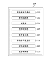
- FIG. 3 is a functional block diagram of the image processing unit.
- FIG. 4 is a diagram showing information recorded in the recording unit.
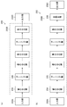
- FIG. 5 is a diagram showing a configuration example of a convolutional neural network.
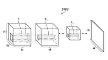
- FIG. 6 is a diagram showing a state of the convolution process by the filter.
- FIG. 7 is a flowchart showing the procedure of the medical image processing method according to the first embodiment.
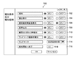
- FIG. 8 is a diagram showing an example of a setting screen of a notification condition and a notification mode.
- FIG. 9 is a diagram showing an example of a method of notifying the determination result.
- FIG. 8 is a diagram showing an example of a setting screen of a notification condition and a notification mode.
- FIG. 10 is another diagram showing an example of a method of notifying the determination result.
- FIG. 11 is still another diagram showing an example of a method of notifying the determination result.
- FIG. 12 is another flowchart showing the procedure of the medical image processing method according to the first embodiment.
- FIG. 13 is still another flowchart showing the procedure of the medical image processing method according to the first embodiment.
- FIG. 1 is an external view of the endoscope system 10 (endoscope system, medical image processing apparatus), and FIG. 2 is a block diagram showing a main configuration of the endoscope system 10.
- the endoscope system 10 includes an endoscope scope 100 (medical image acquisition unit, endoscope scope) and a processor 200 (medical image processing device, processor, medical image acquisition unit, site recognition). It is composed of a unit, a determination unit, a notification unit, a notification control unit, an operation reception unit, a moving direction estimation unit), a light source device 300 (light source device), and a monitor 400 (display device, display).
- the endoscope scope 100 includes a hand operation unit 102 and an insertion unit 104 connected to the hand operation unit 102.
- the operator grasps and operates the hand operation unit 102, inserts the insertion unit 104 into the body of the subject (living body), and observes it.
- the hand operation unit 102 is provided with an air supply / water supply button 141, a suction button 142, a function button 143 to which various functions are assigned, and a shooting button 144 for receiving a shooting instruction operation (still image, moving image). ..
- the insertion portion 104 is composed of a soft portion 112, a curved portion 114, and a tip hard portion 116 in this order from the hand operation portion 102 side.
- the curved portion 114 is connected to the base end side of the hard tip portion 116, and the soft portion 112 is connected to the base end side of the curved portion 114.
- the hand operation unit 102 is connected to the base end side of the insertion unit 104. The user can bend the curved portion 114 and change the direction of the hard tip portion 116 up, down, left and right by operating the hand operating portion 102.
- the tip rigid portion 116 is provided with a photographing optical system 130, an illumination portion 123, a forceps opening 126, and the like (see FIGS. 1 and 2).
- white light and / or narrow band light (red narrow band light, green narrow band light, etc.) are transmitted from the illumination lenses 123A and 123B of the illumination unit 123.
- narrow band light red narrow band light, green narrow band light, etc.
- One or more of blue narrow band light and purple narrow band light can be irradiated.
- cleaning water is discharged from a water supply nozzle (not shown) to clean the photographing lens 132 (photographing lens, photographing unit) of the photographing optical system 130 and the illumination lenses 123A and 123B. Can be done.
- a conduit (not shown) communicates with the forceps opening 126 opened by the hard tip 116, and a treatment tool (not shown) for removing a tumor or the like is inserted into this conduit, and the patient moves back and forth as appropriate to the subject. You can take the necessary measures.
- a photographing lens 132 (photographing portion) is arranged on the tip end surface 116A of the tip rigid portion 116.
- a CMOS (Complementary Metal-Oxide Semiconductor) type image sensor 134 image sensor, image acquisition unit), drive circuit 136, and AFE138 (AFE: Analog Front End, imaging unit) are arranged behind the photographing lens 132.
- An image signal is output by these elements.
- the image pickup element 134 is a color image pickup element, and is composed of a plurality of light receiving elements arranged in a matrix (two-dimensional arrangement) in a specific pattern arrangement (Bayer arrangement, X-Trans (registered trademark) arrangement, honeycomb arrangement, etc.). It has a plurality of pixels.
- Each pixel of the image sensor 134 includes a microlens, a red (R), green (G), or blue (B) color filter and a photoelectric conversion unit (photodiode or the like).
- the photographing optical system 130 can also generate a color image from pixel signals of three colors of red, green, and blue, and generate an image from pixel signals of any one or two colors of red, green, and blue. You can also do it.
- the image sensor 134 may be a CCD (Charge Coupled Device) type. Further, each pixel of the image sensor 134 may further include a purple color filter corresponding to a purple light source 310V and / or an infrared filter corresponding to an infrared light source.
- the optical image of the subject is imaged on the light receiving surface (imaging surface) of the image sensor 134 by the photographing lens 132, converted into an electric signal, output to the processor 200 via a signal cable (not shown), and converted into a video signal.
- a signal cable not shown
- a video signal not shown
- the illumination lenses 123A and 123B of the illumination portion 123 are provided adjacent to the photographing lens 132.
- the ejection ends of the light guide 170 which will be described later, are arranged behind the illumination lenses 123A and 123B, and the light guide 170 is inserted into the insertion portion 104, the hand operation portion 102, and the universal cable 106 to form the light guide 170.
- the incident end is arranged within the light guide connector 108.
- the user performs imaging at a predetermined frame rate while inserting or removing the endoscope scope 100 (insertion unit 104) having the above-described configuration into the living body as the subject (under the control of the medical image acquisition unit 220). By doing so, it is possible to sequentially take time-series images in the living body.
- the light source device 300 includes a light source 310 for illumination, a diaphragm 330, a condenser lens 340, a light source control unit 350, and the like, and causes observation light to enter the light guide 170.
- the light source 310 includes a red light source 310R, a green light source 310G, a blue light source 310B, and a purple light source 310V that irradiate narrow band light of red, green, blue, and purple, respectively, and is narrow in red, green, blue, and purple. It can irradiate band light.
- the illuminance of the observation light by the light source 310 is controlled by the light source control unit 350, and the illuminance of the observation light can be changed (increased or decreased) and the illumination can be stopped as needed.
- the light source 310 can emit red, green, blue, and purple narrow-band light in any combination.
- narrow-band light of red, green, blue, and purple can be emitted at the same time to irradiate white light (normal light) as observation light, or one or two of them can be emitted to emit narrow-band light. It is also possible to irradiate light (special light).
- the light source 310 may further include an infrared light source that irradiates infrared light (an example of narrow band light).
- white light or narrow band light may be irradiated as observation light by a light source that irradiates white light and a filter that transmits white light and each narrow band light.
- the light source 310 may be a light source having a white band or a light source having a plurality of wavelength bands as the light having a white band, or a light source having a specific wavelength band narrower than the white wavelength band.
- the specific wavelength band may be a blue band or a green band in the visible region, or a red band in the visible region.
- a specific wavelength band is a visible blue band or green band, it includes a wavelength band of 390 nm or more and 450 nm or less, or 530 nm or more and 550 nm or less, and peaks in a wavelength band of 390 nm or more and 450 nm or less or 530 nm or more and 550 nm or less. It may have a wavelength.
- the light in the specific wavelength band includes the wavelength band of 585 nm or more and 615 nm or less, or 610 nm or more and 730 nm or less, and the light in the specific wavelength band is 585 nm or more and 615 nm or less or 610 nm or more. It may have a peak wavelength in the wavelength band of 730 nm or less.
- the specific wavelength band includes a wavelength band of 400 ⁇ 10 nm, 440 ⁇ 10 nm, 470 ⁇ 10 nm, or 600 nm or more and 750 nm, and 400 ⁇ 10 nm, 440 ⁇ 10 nm, 470 ⁇ 10 nm, or 600 nm or more and 750 nm. It may have a peak wavelength in the following wavelength band.
- the light generated by the light source 310 may include a wavelength band of 790 nm or more and 820 nm or less, or 905 nm or more and 970 nm or less, and may have a peak wavelength in a wavelength band of 790 nm or more and 820 nm or less or 905 nm or more and 970 nm or less.
- the light source 310 may include a light source that irradiates excitation light having a peak of 390 nm or more and 470 nm or less.
- a medical image medical image, in-vivo image
- a dye for the fluorescence method fluorestin, acridine orange, etc.
- the light source type (laser light source, xenon light source, LED light source (LED: Light-Emitting Diode), etc.), wavelength, presence / absence of filter, etc. of the light source 310 are preferably configured according to the type of subject, the part, the purpose of observation, and the like.
- switching the wavelength for example, by rotating a disk-shaped filter (rotary color filter) arranged in front of the light source and provided with a filter that transmits or blocks light of a specific wavelength, the wavelength of the emitted light is switched. May be good.
- the image sensor used in carrying out the present invention is not limited to the color image sensor in which the color filter is arranged for each pixel like the image sensor 134, and may be a monochrome image sensor.
- the wavelength of the observation light can be sequentially switched to perform surface-sequential (color-sequential) imaging.
- the wavelength of the emitted observation light may be sequentially switched between (purple, blue, green, red), or a rotary color filter (red, green, blue, purple, etc.) is irradiated with broadband light (white light). You may switch the wavelength of the observation light emitted by.
- the wavelength of the observation light emitted by the rotary color filter (green, blue, purple, etc.) by irradiating one or a plurality of narrow band lights (green, blue, purple, etc.) may be switched.
- the narrow-band light may be infrared light having two or more wavelengths (first narrow-band light, second narrow-band light) having different wavelengths.
- the observation light emitted from the light source device 300 is transmitted to the illumination lenses 123A and 123B via the light guide 170, and the illumination lens
- the observation range is irradiated from 123A and 123B.
- the configuration of the processor 200 will be described with reference to FIG.
- the processor 200 inputs the image signal output from the endoscope scope 100 via the image input controller 202, performs necessary image processing in the image processing unit 204 (medical image processing unit, processor), and performs necessary image processing in the video output unit 206. Output via.
- the observation image (in-vivo image) is displayed on the monitor 400 (display device).
- CPU Central Processing Unit
- the communication control unit 205 controls communication with respect to the acquisition of medical images, etc. between an in-hospital system (HIS: Hospital Information System), an in-hospital LAN (Local Area Network), and / or an external system or network (not shown). I do.
- FIG. 3 is a functional block diagram of the image processing unit 204.
- the image processing unit 204 includes a medical image acquisition unit 220 (medical image acquisition unit, image acquisition unit), a site recognition unit 222 (site recognition unit), a determination unit 224 (determination unit), and a notification control unit 226 (notification control unit). ),
- the operation reception unit 227 operation reception unit
- the movement direction estimation unit 228 movement direction estimation unit
- the recording control unit 229 recording control unit
- display control unit 230 display control unit
- the image processing unit 204 uses the above-mentioned functions to calculate the feature amount of the medical image, process to emphasize or reduce the components of a specific frequency band, and emphasize or emphasize a specific target (area of interest, blood vessel of desired depth, etc.). It is possible to perform processing that makes it inconspicuous.
- the image processing unit 204 acquires special light having information in a specific wavelength band based on a normal light image obtained by irradiating light in a white band or light in a plurality of wavelength bands as light in the white band.
- An image acquisition unit may be provided.
- the signal of a specific wavelength band is used for RGB (R: red, G: green, B: blue) or CMY (C: cyan, M: magenta, Y: yellow) color information included in a normal optical image. It can be obtained by the calculation based on.
- the image processing unit 204 includes a normal light image obtained by irradiating light in a white band or light in a plurality of wavelength bands as light in the white band, and a special light image obtained by irradiating light in a specific wavelength band.
- a feature amount image generation unit that generates a feature amount image by an operation based on at least one of the above may be provided, and a feature amount image as a medical image (medical image) may be acquired and displayed. The above-mentioned processing is performed under the control of the CPU 210.
- Various processors include, for example, a CPU (Central Processing Unit), which is a general-purpose processor that executes software (programs) to realize various functions.
- the various processors described above include programmable logic devices (PLCs) such as GPUs (Graphics Processing Units) and FPGAs (Field Programmable Gate Arrays), which are specialized processors for image processing, whose circuit configurations can be changed after manufacturing.
- PLCs programmable logic devices
- GPUs Graphics Processing Units
- FPGAs Field Programmable Gate Arrays
- PLD Programmable Logic Device
- the above-mentioned various processors also include a dedicated electric circuit, which is a processor having a circuit configuration specially designed for executing a specific process such as an ASIC (Application Specific Integrated Circuit).
- each part may be realized by one processor, or may be realized by a plurality of processors of the same type or different types (for example, a plurality of FPGAs, or a combination of a CPU and an FPGA, or a combination of a CPU and a GPU). Further, a plurality of functions may be realized by one processor. As an example of configuring a plurality of functions with one processor, first, as represented by a computer, one processor is configured by a combination of one or more CPUs and software, and this processor is used as a plurality of functions. There is a form to be realized.
- SoC System On Chip
- a processor that realizes the functions of the entire system with one IC (Integrated Circuit) chip
- various functions are configured by using one or more of the above-mentioned various processors as a hardware structure.
- the hardware structure of these various processors is, more specifically, an electric circuit (circuitry) in which circuit elements such as semiconductor elements are combined.
- These electric circuits may be electric circuits that realize the above-mentioned functions by using logical sum, logical product, logical denial, exclusive logical sum, and logical operations combining these.
- the processor or electric circuit executes software (program), it can be read by a computer of the software (for example, various processors and electric circuits constituting the image processing unit 204, and / or a combination thereof).
- the code is stored in a non-temporary recording medium such as ROM 211 (ROM: Read Only Memory), and the computer refers to the software.
- the software stored in the non-temporary recording medium is a program for executing the operation method of the medical image processing apparatus according to the present invention and data used for execution (data related to acquisition of medical images, notification conditions, and notification modes). Includes data used for identification, parameters used in the recognition unit, etc.).
- the code may be recorded on a non-temporary recording medium such as various optical magnetic recording devices or semiconductor memories instead of the ROM 211.
- a non-temporary recording medium such as various optical magnetic recording devices or semiconductor memories instead of the ROM 211.
- RAM212 RAM: Random Access Memory
- EEPROM Electrically Erasable and Programmable Read Only Memory
- the recording unit 207 may be used as the “non-temporary recording medium”.
- the ROM 211 (ROM: Read Only Memory) is a non-volatile storage element (non-temporary recording medium), and various image processing methods (including the operation method of the medical image processing device according to the present invention) are used in the CPU 210 and /. Alternatively, a computer-readable code of a program to be executed by the image processing unit 204 (computer) is stored.
- the RAM 212 (RAM: Random Access Memory) is a storage element for temporary storage during various processes, and can also be used as a buffer for image acquisition.
- the voice processing unit 209 outputs a message (voice) related to medical image processing, site recognition, notification, etc. from the speaker 209A (notification unit, speaker) under the control of the CPU 210 and the image processing unit 204.
- the operation unit 208 can be configured by a device such as a keyboard and a mouse (not shown), and the user can instruct the execution of medical image processing via the operation unit 208 (operation reception unit) and conditions necessary for execution (for example, which will be described later). Notification conditions and notification mode settings) can be specified.
- the operation via the operation unit 208 includes setting of notification conditions and notification modes (see FIG. 8), and operations indicating that acquisition of medical images of a plurality of parts to be imaged has been completed.
- the operation reception unit 227 described above receives a user's operation via the operation unit 208, and processing is performed by each unit of the CPU 210 and the image processing unit 204 according to the received operation.
- the recording unit 207 (recording device, memory, non-temporary recording medium) has an endoscopic image 260 (endoscopic image, medical image, medical image) and site information 262 (site information; subject). (Information indicating a plurality of parts to be photographed), part recognition result 264 (recognition result of a part of a subject shown in a medical image), judgment result 266 (a part of a plurality of parts to be photographed that has not been photographed). Judgment result) etc. are recorded.
- the site information 262 may be in the form of an image, or may be in the form of a list composed of letters and numbers (for example, "chest esophagus 1", “middle body B", “lesser curvature side of the angular incisure") and the like. It may be in the form.
- the site recognition unit 222 can be configured by using a trained model such as a neural network (a model trained using an image set composed of images of a living body).
- a trained model such as a neural network (a model trained using an image set composed of images of a living body).
- a CNN Convolutional Neural Network
- FIG. 5 is a diagram showing the configuration of CNN232 (neural network).
- the CNN 232 has an input layer 232A (input unit), an intermediate layer 232B, and an output layer 232C.
- the input layer 232A inputs an endoscopic image (medical image) acquired by the medical image acquisition unit 220 and outputs a feature amount.
- the intermediate layer 232B includes the convolution layer 234 and the pooling layer 235, and the feature amount output by the input layer 232A is input to calculate other feature amounts.
- These layers have a structure in which a plurality of "nodes” are connected by “edges”, and the weighting coefficient applied to the input image is associated with the node and the edge and stored in a weighting coefficient storage unit (not shown). It is remembered. The value of the weighting factor changes as the learning progresses.
- the intermediate layer 232B calculates the feature amount by the convolution calculation and the pooling process.
- the convolution operation performed in the convolution layer 234 is a process of acquiring a feature map by a convolution operation using a filter, and plays a role of feature extraction such as edge extraction from an image. By the convolution operation using this filter, one channel (one sheet) of "feature map” is generated for one filter. The size of the "feature map”, if downscaled by convolution, becomes smaller as each layer is convolved.
- the pooling process performed in the pooling layer 235 is a process of reducing (or enlarging) the feature map output by the convolution operation to make a new feature map, so that the extracted features are not affected by translation or the like. Plays the role of giving robustness to.
- the intermediate layer 232B can be composed of one or a plurality of layers that perform these processes.
- the CNN232 may be configured without the pooling layer 235.
- CNN232 may include a fully bonded layer 236 as in the example shown in part (b) of FIG.
- the layer structure of CNN232 is not limited to the case where the convolution layer 234 and the pooling layer 235 are repeated one by one, and any one layer (for example, the convolution layer 234) may be continuously included.
- FIG. 6 is a schematic view showing a configuration example of the intermediate layer 232B of the CNN 232 shown in FIG.
- the convolution layer of the first intermediate layer 232B (1 th) an image set including a plurality of medical images convolution (time learning training image set, at sites recognized image set for site recognition) and the filter F 1 The operation is performed.
- the image set is composed of N images (N channels) having an image size of H in the vertical direction and W in the horizontal direction.
- the images constituting the image set are three-channel images of R (red), G (green), and B (blue).
- the filter size is 5 ⁇ 5 ⁇ N.
- the filter F 2 used in the second convolution layer has a filter size of 3 ⁇ 3 ⁇ M, for example, in the case of a size 3 (3 ⁇ 3) filter.
- the second to nth convolution layers perform convolution operations using filters F 2 to F n.
- the size of the "feature map" in the nth convolution layer is smaller than the size of the "feature map” in the second convolution layer because it is downscaled by the convolution layer or pooling layer up to the previous stage. Is.
- lower-order feature extraction (edge extraction, etc.) is performed in the convolution layer closer to the input side, and higher-order feature extraction (features related to the shape, structure, etc. of the recognition target) is performed as the intermediate layer 232B approaches the output side. Extraction) is performed.
- the intermediate layer 232B may include a layer for batch normalization in addition to the convolution layer 234 and the pooling layer 235.
- the batch normalization process is a process of normalizing the distribution of data in units of mini-batch when learning, and plays a role of advancing learning quickly, reducing dependence on initial values, suppressing overfitting, and the like.
- the output layer 232C outputs the feature amount calculated by the intermediate layer 232B in a format suitable for site recognition.
- the output layer 232C may include a fully connected layer.
- FIG. 7 is a flowchart showing an outline of processing of the medical image processing method (operation method of the medical image processing device) according to the first embodiment. It is assumed that the learning of CNN232 using the learning data has been executed.
- the image processing unit 204 (notification control unit 226) sets the notification condition and the notification mode according to the user's operation via the operation unit 208 (step S100: notification condition setting step, notification mode setting step).
- the user can perform the setting operation via the screen 700 (displayed on the monitor 400) illustrated in FIG.
- the screen 700 has areas 702 to 712 in which radio buttons are arranged, areas 714 in which pull-down menus are arranged, and areas 716 in which numerical input fields are arranged.
- the user can set whether or not to perform the notification (on or off; area 702) by operating the radio button.
- the user operates the radio button to display "whether or not to perform notification” (area 702), "whether or not to perform notification by screen display” (area 704), and “display the notification screen in the initial state”. "Whether or not” (Region 706; see the examples of FIGS. 10 and 11), "Whether or not to perform notification by voice output (voice signal)" (Region 708).
- the user can operate the radio button to "whether or not to notify at the timing when the organ of the subject shown in the medical image is switched" (area 710) and "a predetermined part (so-called” landmark "). Whether or not to give notification at the timing when the medical image of the subject in ") is taken” (region 712) can be set.
- the radio button of the area 712 is turned on, the user can select a part to be a landmark by operating the pull-down menu of the area 714.
- “esophaogastric junction (EGJ)” is selected as the landmark, but the landmark may be another site (for example, pharynx).
- timing at which the organ of the subject shown in the medical image is switched and “timing at which the medical image of the subject is taken at a predetermined portion” are the “expected end timing” (plurality to be captured) in the present invention. This is an example of (timing when it is expected that the acquisition of medical images for the site) is completed.
- the user sets "the elapsed time from the start to the end of the notification (from the switching from the notification state to the non-notification state)" ("predetermined time") by inputting the numerical value in the area 716. can do.
- the notification control unit 226 switches the notification by the monitor 400 and / or the speaker 209A from the notification state to the non-notification state (stops or ends the notification) after the time (seconds) input to the area 716 has elapsed. In the example of FIG. 8, it takes 1.0 seconds from the start to the end of the notification.
- Numerical value input may be a method of selecting a predetermined numerical value from a pull-down menu.
- the notification control unit 226 may reduce (reduce) the notification power after the lapse of a designated time.
- the user can set the notification condition and the notification mode as needed, and the notification control unit 226 notifies (supports) according to the setting contents. ), Excessive notification can be suppressed.
- the above example is an example of setting, and other items (notification by light or vibration, etc.) may be set.
- the notification condition and the notification mode may be set not only at the start of the medical image processing but also at an arbitrary timing during the processing.
- the endoscopy system 10 may automatically set the notification conditions and the notification mode without the user's operation.
- the medical image acquisition unit 220 acquires a time-series endoscopic image (medical image) (step S110: image acquisition step).
- the medical image acquisition unit 220 may acquire an endoscopic image taken by the endoscope scope 100, or may acquire an endoscopic image 260 recorded by the recording unit 207.
- the recording control unit 229 can record the acquired image as an endoscopic image 260 in the recording unit 207.
- the part recognition unit 222 (part recognition unit, processor) recognizes the part (photographed part) of the subject in the endoscopic image acquired in step S110 by using the above-mentioned CNN232 (step S120: part). Recognition process).
- the site include the cervical esophagus, the thoracic esophagus, and the abdominal esophagus in the case of the esophagus.
- the thoracic esophagus may be further divided into an upper thoracic esophagus, a middle thoracic esophagus, and a lower thoracic esophagus.
- the cardia, the pylorus (fundus), the body of the stomach, the angular incisure, the antrum, the anterior pylorus, and the pylorus ring can be mentioned.
- the body of the stomach may be further divided into upper, middle and lower parts. Further, the circumferential direction may be divided into the lesser curvature, the front wall, the greater curvature, and the rear wall.
- the site recognition unit 222 indicates that the specific subject is in a predetermined area of the endoscopic image (for example,). , Center), a specific subject is reflected in the endoscopic image with a size larger than the specified size, and a specific subject is more than the specified degree of focus in the endoscopic image. If at least one of them is satisfied, it may be determined that the site has been recognized.
- the recording control unit 229 records the imaged portion information (site recognition result) as the site recognition result 264 in the recording unit 207 (step S130: recognition result recording step).
- the recording control unit 229 preferably records the site recognition result in association with the endoscopic image.
- the recording control unit 229 may record the site recognition result in the above-mentioned list format.
- the determination unit 224 compares the part recognized in step S130 (part recognition result 264) with the part indicated by the part information 262, and among a plurality of parts to be photographed, the part not photographed (the unphotographed part). (Step S140: determination step).
- the determination unit 224 can determine, for example, the presence or absence of an unphotographed portion and / or which portion has not been imaged.
- the determination unit 224 may make a determination every time one or a plurality of images are acquired, or may make a determination every time a designated time elapses.
- the notification control unit 226 determines whether or not the expected end timing, which is expected to complete the acquisition of endoscopic images (medical images) for a plurality of parts to be imaged, has arrived (step S150: notification step). ).
- the timing at which the site to be observed changes from one organ to another organ in the recognition result (for example, the timing when the esophagus changes to the stomach; set in region 710 in the example of FIG. 8), a predetermined site.
- the timing at which the medical image of the subject in the above image is acquired (the timing at which the image of the landmark is acquired; set in the areas 712 and 714 in the example of FIG. 8) can be set as the expected end timing.
- the timing at which the user's operation indicating the end of shooting for the determined range is accepted (the timing at which the operation reception unit 227 accepts the user's operation via the operation unit 208), that is, the user "shooting is completed”.
- the timing recognized as “expected end timing” may be used.
- the notification control unit 226 may determine the arrival of the expected end timing based on the number of shots determined and the expiration of the shooting time. In the "expected end timing", it is sufficient if the acquisition of the endoscopic image is expected to be completed (if there is a possibility), and the acquisition does not have to be actually completed.
- the moving direction estimation unit 228 (moving direction estimating unit) estimates the moving direction (insertion or removal) of the endoscope scope 100 based on, for example, the movement vector of the subject, and the moving direction is removed from the insertion (forward direction) (moving direction).
- the timing that changes in the backward direction) may be set as the "expected end timing”.
- the timing at which the user reverses the direction of the tip portion of the endoscope scope 100 and performs so-called “looking up” (the timing at which the endoscope scope 100 appears in the endoscope image) is set as the "expected end timing". May be good.
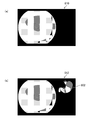
- FIG. 9 is a diagram showing an example of notification about the stomach.
- the part (a) in FIG. 9 is a diagram showing a state before the start of observation (all parts have not been observed), and in the image 800 showing a schema diagram (schematic diagram) of the stomach, the entire region is not colored (shaded). be.
- the part (b) in the figure is a diagram showing the notification state at the expected end timing, and the parts observed in the image 802 (the lesser curvature part, the body of the stomach, the vestibule part, the anterior part of the pylorus, The gastric corpus pyloric side) is displayed in color, and the unobserved part (angular incisure lesser curvature side) is uncolored.
- a symbol (circle 804) surrounding an unobserved part is attached.
- the schema diagram of the organ esophagus, stomach, etc.
- the notification control unit 226 may color the schema diagram during normal observation and leave the observed portion uncolored (or lighten the color) at the time of notification. Further, the color may be changed between the observed part and the unobserved part, the color may be changed at the timing of notification, or the unobserved part may be blinked.
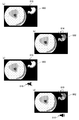
- FIG. 10 is a diagram showing a display example on the monitor 400 (display).
- Part (a) of FIG. 10 shows a state at the time of normal observation (a state in which the expected end timing has not arrived), and only the endoscopic image 810 (normal observation image) is displayed.
- the part (b) in the figure shows the notification state at the expected end timing, and the endoscopic image 812 on which the image 802 (see FIG. 9) showing the unobserved portion is superimposed and displayed is displayed.
- the notification control unit 226 may display the image 802 on a screen different from the endoscopic image.
- the notification control unit 226 newly displays the information (image 802) that was not displayed on the screen before the notification is performed, but in addition to or instead of the screen display. Therefore, the sound that was not output before the notification may be newly output from the speaker 209A.
- the notification control unit 226 outputs a warning sound such as a beep sound when there is an unphotographed part, or a sound indicating an unphotographed part such as "the lesser curvature side of the angular incisure is not photographed" at the time of notification. This makes it possible to notify.
- the user can operate the endoscope scope 100 in response to the notification indicating such unphotographed (observation omission) to image (observe) the unphotographed portion, so that the observation omission can be detected. Can be prevented. Further, since the endoscope system 10 notifies at an appropriate timing (expected end timing), there is no possibility of interfering with the observation.
- the notification control unit 226 colors the schema diagram with the same color, circles the entire schema diagram (when the screen is displayed), and so on. It is preferable to perform notification in a manner different from that when there is an unphotographed part, such as outputting a voice such as "There is no".
- the notification control unit 226 may reduce the notification power (for example, reduce the schema diagram, lower the volume, etc.) as compared with the case where there is an unphotographed portion.
- the CPU 210 and the image processing unit 204 repeat the processes of steps S110 to S160 until the observation is completed (between NO in step S170).
- the medical image processing device As described above, according to the medical image processing device, the operating method of the medical image processing device, and the endoscopic system according to the present invention, it is possible to notify the observation omission at an appropriate timing.
- the stomach schema diagram (image 802) is not superimposed and displayed during normal observation (the screen display during normal observation is off; the radio button is turned off in the area 706 of FIG. 8).
- the schema diagram for example, the image 800 shown in FIG. 9 may be superimposed and displayed even during normal observation (the image display during normal observation is on).
- the notification control unit 226 blinks the image 802 on the screen of the monitor 400 at the time of notification (expected end timing).
- the aspect shown in FIG. 11 is an aspect of notifying by changing the display mode of the information (image 800) already displayed on the screen of the monitor 400 (display).
- the notification control unit 226 may perform notification by changing the output mode of the voice already output from the speaker 209A in addition to or instead of displaying the information on the screen.
- the notification control unit 226 can increase the notification power by changing, for example, the voice output during normal observation and the voice content (message content), volume, pitch, pattern, etc. at the expected end timing. ..
- the part (c) of FIG. 11 shows the state at the time of normal observation (the image 800 is displayed; the icon 816 is marked with a cross and there is no audio output), and the part (d) of the figure shows the state at the time of notification. (Blinking and audio output of image 802; icon 818 is displayed).
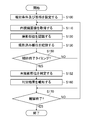
- the unphotographed portion is continuously determined at a timing other than the expected end timing, but as shown in FIG. 12, the determination unit 224 determines the expected end timing (for example, the timing at which the user's instruction is received.
- the determination of the unphotographed portion may be performed at the timing when the observed organ changes or when the landmark image is acquired). Since the flowchart of FIG. 12 is the same as that of FIG. 7 except for step S152, the description of the same portion will be omitted.
- the notification control unit 226 reduces the notification power after a certain period of time has passed from the notification (including the end of the notification). (See Steps S162, S164: Notification Step, Region 716 of FIG. 8).
- ⁇ Modified example of site recognition method> In the first embodiment described above, the case where the site recognition unit 222 performs the site recognition using the CNN has been described, but the site recognition is not limited to the CNN, but the support vector machine (SVM) and the k-nearest neighbor method (A general multi-class classification method based on supervised learning such as k-NN: k-Nearest Neighbor) can be used.
- SVM support vector machine
- k-nearest neighbor method A general multi-class classification method based on supervised learning such as k-NN: k-Nearest Neighbor
- the medical image analysis processing unit detects a region of interest, which is a region of interest, based on the feature amount of pixels of the medical image.
- the medical image analysis result acquisition unit is a medical image processing device that acquires the analysis results of the medical image analysis processing unit.
- the medical image analysis processing unit detects the presence or absence of a noteworthy object based on the feature amount of the pixel of the medical image.
- the medical image analysis result acquisition unit is a medical image processing device that acquires the analysis results of the medical image analysis processing unit.
- the medical image analysis result acquisition department Obtained from a recording device that records the analysis results of medical images
- the analysis result is a medical image processing apparatus that is a region of interest that is a region of interest included in a medical image, a presence or absence of an object of interest, or both.
- a medical image is a medical image processing apparatus that is a normal light image obtained by irradiating light in a white band or light in a plurality of wavelength bands as light in a white band.
- a medical image is an image obtained by irradiating light in a specific wavelength band.
- a medical image processing device in which a specific wavelength band is narrower than the white wavelength band.
- a medical image processing device in which a specific wavelength band is a blue or green band in the visible range.
- a medical treatment in which a specific wavelength band includes a wavelength band of 390 nm or more and 450 nm or less or 530 nm or more and 550 nm or less, and light in a specific wavelength band has a peak wavelength in a wavelength band of 390 nm or more and 450 nm or less or 530 nm or more and 550 nm or less.
- Image processing device
- the specific wavelength band includes a wavelength band of 585 nm or more and 615 nm or less or 610 nm or more and 730 nm or less, and the light of the specific wavelength band has a peak wavelength in the wavelength band of 585 nm or more and 615 nm or less or 610 nm or more and 730 nm or less.
- Image processing device includes a wavelength band of 585 nm or more and 615 nm or less or 610 nm or more and 730 nm or less, and the light of the specific wavelength band has a peak wavelength in the wavelength band of 585 nm or more and 615 nm or less or 610 nm or more and 730 nm or less.
- the specific wavelength band includes a wavelength band in which the extinction coefficient differs between the oxidized hemoglobin and the reduced hemoglobin, and the light in the specific wavelength band has a peak wavelength in the wavelength band having a different extinction coefficient between the oxidized hemoglobin and the reduced hemoglobin.
- Medical image processing device includes a wavelength band in which the extinction coefficient differs between the oxidized hemoglobin and the reduced hemoglobin, and the light in the specific wavelength band has a peak wavelength in the wavelength band having a different extinction coefficient between the oxidized hemoglobin and the reduced hemoglobin.
- the specific wavelength band includes 400 ⁇ 10 nm, 440 ⁇ 10 nm, 470 ⁇ 10 nm, or 600 nm or more and 750 nm or less, and the light in the specific wavelength band is 400 ⁇ 10 nm, 440 ⁇ 10 nm, 470 ⁇ .
- a medical image processing apparatus having a peak wavelength in a wavelength band of 10 nm or 600 nm or more and 750 nm or less.
- a medical image is an in-vivo image that shows the inside of a living body.
- An in-vivo image is a medical image processing device that has information on fluorescence emitted by a fluorescent substance in the living body.
- Fluorescence is a medical image processing device obtained by irradiating a living body with excitation light having a peak of 390 or more and 470 nm or less.
- a medical image is an in-vivo image that shows the inside of a living body.
- a specific wavelength band is a medical image processing device that is a wavelength band of infrared light.
- a medical image in which a specific wavelength band includes a wavelength band of 790 nm or more and 820 nm or less or 905 nm or more and 970 nm or less, and light in a specific wavelength band has a peak wavelength in a wavelength band of 790 nm or more and 820 nm or less or 905 nm or more and 970 nm or less. Processing equipment.
- the medical image acquisition unit acquires a special optical image having information in a specific wavelength band based on a normal light image obtained by irradiating light in a white band or light in a plurality of wavelength bands as light in the white band. Equipped with an optical image acquisition unit
- the medical image is a medical image processing device that is a special optical image.
- Appendix 17 A medical image processing device that obtains a signal in a specific wavelength band by calculation based on RGB or CMY color information included in a normal optical image.
- Appendix 18 By calculation based on at least one of a normal light image obtained by irradiating light in a white band or light in a plurality of wavelength bands as light in a white band and a special light image obtained by irradiating light in a specific wavelength band. Equipped with a feature amount image generator that generates a feature amount image A medical image is a medical image processing device that is a feature image.
Abstract
L'objectif de la présente invention est de fournir un dispositif de traitement d'images médicales pouvant fournir une notification d'une omission d'observation à un moment approprié, un procédé pour faire fonctionner le dispositif de traitement d'images médicales, et un système endoscopique. Un dispositif de traitement d'images médicales selon un aspect de la présente invention est doté : d'une mémoire dans laquelle sont stockées des informations de site indiquant un site prédéterminé d'un sujet devant être photographié ; d'un processeur ; et d'une unité de notification. Le processeur acquiert une image médicale du sujet, reconnaît le site du sujet qui a été photographié dans l'image médicale, compare le site reconnu et le site indiqué par les informations de site, détermine, parmi des sites qui doivent être photographiés, un site qui n'a pas été photographié, et fournit une notification, par l'intermédiaire de l'unité de notification, du résultat de détermination à un moment de fin anticipé auquel il est anticipé que l'acquisition d'images médicales des sites devant être photographiés prendra fin.
Priority Applications (4)
| Application Number | Priority Date | Filing Date | Title |
|---|---|---|---|
| EP21744902.4A EP4094673A4 (fr) | 2020-01-20 | 2021-01-13 | Dispositif de traitement d'images médicales, procédé de fonctionnement de dispositif de traitement d'images médicales, et système endoscopique |
| CN202180009009.7A CN114945315A (zh) | 2020-01-20 | 2021-01-13 | 医疗图像处理装置、医疗图像处理装置的动作方法、及内窥镜系统 |
| JP2021573084A JPWO2021149552A5 (ja) | 2021-01-13 | 医療画像処理装置、内視鏡システム、及び医療画像処理装置の作動方法 | |
| US17/809,218 US20220327702A1 (en) | 2020-01-20 | 2022-06-27 | Medical image processing apparatus, method for operating medical image processing apparatus, and endoscope system |
Applications Claiming Priority (2)
| Application Number | Priority Date | Filing Date | Title |
|---|---|---|---|
| JP2020006928 | 2020-01-20 | ||
| JP2020-006928 | 2020-01-20 |
Related Child Applications (1)
| Application Number | Title | Priority Date | Filing Date |
|---|---|---|---|
| US17/809,218 Continuation US20220327702A1 (en) | 2020-01-20 | 2022-06-27 | Medical image processing apparatus, method for operating medical image processing apparatus, and endoscope system |
Publications (1)
| Publication Number | Publication Date |
|---|---|
| WO2021149552A1 true WO2021149552A1 (fr) | 2021-07-29 |
Family
ID=76992296
Family Applications (1)
| Application Number | Title | Priority Date | Filing Date |
|---|---|---|---|
| PCT/JP2021/000820 WO2021149552A1 (fr) | 2020-01-20 | 2021-01-13 | Dispositif de traitement d'images médicales, procédé de fonctionnement de dispositif de traitement d'images médicales, et système endoscopique |
Country Status (4)
| Country | Link |
|---|---|
| US (1) | US20220327702A1 (fr) |
| EP (1) | EP4094673A4 (fr) |
| CN (1) | CN114945315A (fr) |
| WO (1) | WO2021149552A1 (fr) |
Cited By (3)
| Publication number | Priority date | Publication date | Assignee | Title |
|---|---|---|---|---|
| WO2023112499A1 (fr) * | 2021-12-13 | 2023-06-22 | 富士フイルム株式会社 | Dispositif endoscopique d'assistance à l'observation d'image et système d'endoscope |
| WO2023145078A1 (fr) * | 2022-01-31 | 2023-08-03 | オリンパスメディカルシステムズ株式会社 | Système d'assistance médicale et méthode d'assistance médicale |
| WO2024048098A1 (fr) * | 2022-08-30 | 2024-03-07 | 富士フイルム株式会社 | Dispositif d'assistance médicale, endoscope, méthode d'assistance médicale et programme |
Citations (11)
| Publication number | Priority date | Publication date | Assignee | Title |
|---|---|---|---|---|
| JP2012070936A (ja) * | 2010-09-28 | 2012-04-12 | Fujifilm Corp | 内視鏡システム、内視鏡画像取得支援方法、及びプログラム |
| JP2016002206A (ja) * | 2014-06-16 | 2016-01-12 | オリンパス株式会社 | 医療情報処理システム |
| JP2016062488A (ja) * | 2014-09-19 | 2016-04-25 | オリンパス株式会社 | 内視鏡業務支援システム |
| JP2018050890A (ja) | 2016-09-28 | 2018-04-05 | 富士フイルム株式会社 | 画像表示装置及び画像表示方法並びにプログラム |
| WO2018159461A1 (fr) * | 2017-03-03 | 2018-09-07 | 富士フイルム株式会社 | Système d'endoscope, dispositif de processeur, et procédé de fonctionnement du système d'endoscope |
| JP2018139848A (ja) * | 2017-02-28 | 2018-09-13 | 富士フイルム株式会社 | 内視鏡システム及びその作動方法 |
| JP2018139847A (ja) * | 2017-02-28 | 2018-09-13 | 富士フイルム株式会社 | 内視鏡システム及びその作動方法 |
| WO2018221033A1 (fr) * | 2017-06-02 | 2018-12-06 | 富士フイルム株式会社 | Dispositif de traitement des images médicales, système d'endoscope, dispositif d'aide au diagnostic et dispositif d'aide au travail médical |
| WO2018225448A1 (fr) * | 2017-06-09 | 2018-12-13 | 智裕 多田 | Procédé de support de diagnostic de maladie, système de support de diagnostic et programme de support de diagnostic utilisant une image endoscopique d'un organe digestif, et support d'enregistrement lisible par ordinateur ayant ledit programme de support de diagnostic stocké sur celui-ci |
| WO2020090729A1 (fr) * | 2018-11-01 | 2020-05-07 | 富士フイルム株式会社 | Appareil de traitement d'image médicale, procédé de traitement d'image médicale et appareil d'assistance au diagnostic |
| JP2020146202A (ja) * | 2019-03-13 | 2020-09-17 | 富士フイルム株式会社 | 内視鏡画像処理装置、方法及びプログラム、内視鏡システム |
Family Cites Families (5)
| Publication number | Priority date | Publication date | Assignee | Title |
|---|---|---|---|---|
| JP5810248B2 (ja) * | 2013-10-02 | 2015-11-11 | オリンパス株式会社 | 内視鏡システム |
| CN108135453B (zh) * | 2015-09-28 | 2021-03-23 | 奥林巴斯株式会社 | 内窥镜系统和图像处理方法 |
| WO2019245009A1 (fr) * | 2018-06-22 | 2019-12-26 | 株式会社Aiメディカルサービス | Procédé d'aide au diagnostic d'une maladie sur la base d'une image endoscopique d'un organe digestif, système d'aide au diagnostic, programme d'aide au diagnostic et support d'enregistrement lisible par ordinateur sur lequel est stocké ledit programme d'aide au diagnostic |
| JPWO2021132023A1 (fr) * | 2019-12-26 | 2021-07-01 | ||
| JP7289373B2 (ja) * | 2020-01-17 | 2023-06-09 | 富士フイルム株式会社 | 医療画像処理装置、内視鏡システム、診断支援方法及びプログラム |
-
2021
- 2021-01-13 EP EP21744902.4A patent/EP4094673A4/fr active Pending
- 2021-01-13 WO PCT/JP2021/000820 patent/WO2021149552A1/fr unknown
- 2021-01-13 CN CN202180009009.7A patent/CN114945315A/zh active Pending
-
2022
- 2022-06-27 US US17/809,218 patent/US20220327702A1/en active Pending
Patent Citations (11)
| Publication number | Priority date | Publication date | Assignee | Title |
|---|---|---|---|---|
| JP2012070936A (ja) * | 2010-09-28 | 2012-04-12 | Fujifilm Corp | 内視鏡システム、内視鏡画像取得支援方法、及びプログラム |
| JP2016002206A (ja) * | 2014-06-16 | 2016-01-12 | オリンパス株式会社 | 医療情報処理システム |
| JP2016062488A (ja) * | 2014-09-19 | 2016-04-25 | オリンパス株式会社 | 内視鏡業務支援システム |
| JP2018050890A (ja) | 2016-09-28 | 2018-04-05 | 富士フイルム株式会社 | 画像表示装置及び画像表示方法並びにプログラム |
| JP2018139848A (ja) * | 2017-02-28 | 2018-09-13 | 富士フイルム株式会社 | 内視鏡システム及びその作動方法 |
| JP2018139847A (ja) * | 2017-02-28 | 2018-09-13 | 富士フイルム株式会社 | 内視鏡システム及びその作動方法 |
| WO2018159461A1 (fr) * | 2017-03-03 | 2018-09-07 | 富士フイルム株式会社 | Système d'endoscope, dispositif de processeur, et procédé de fonctionnement du système d'endoscope |
| WO2018221033A1 (fr) * | 2017-06-02 | 2018-12-06 | 富士フイルム株式会社 | Dispositif de traitement des images médicales, système d'endoscope, dispositif d'aide au diagnostic et dispositif d'aide au travail médical |
| WO2018225448A1 (fr) * | 2017-06-09 | 2018-12-13 | 智裕 多田 | Procédé de support de diagnostic de maladie, système de support de diagnostic et programme de support de diagnostic utilisant une image endoscopique d'un organe digestif, et support d'enregistrement lisible par ordinateur ayant ledit programme de support de diagnostic stocké sur celui-ci |
| WO2020090729A1 (fr) * | 2018-11-01 | 2020-05-07 | 富士フイルム株式会社 | Appareil de traitement d'image médicale, procédé de traitement d'image médicale et appareil d'assistance au diagnostic |
| JP2020146202A (ja) * | 2019-03-13 | 2020-09-17 | 富士フイルム株式会社 | 内視鏡画像処理装置、方法及びプログラム、内視鏡システム |
Non-Patent Citations (1)
| Title |
|---|
| See also references of EP4094673A4 |
Cited By (3)
| Publication number | Priority date | Publication date | Assignee | Title |
|---|---|---|---|---|
| WO2023112499A1 (fr) * | 2021-12-13 | 2023-06-22 | 富士フイルム株式会社 | Dispositif endoscopique d'assistance à l'observation d'image et système d'endoscope |
| WO2023145078A1 (fr) * | 2022-01-31 | 2023-08-03 | オリンパスメディカルシステムズ株式会社 | Système d'assistance médicale et méthode d'assistance médicale |
| WO2024048098A1 (fr) * | 2022-08-30 | 2024-03-07 | 富士フイルム株式会社 | Dispositif d'assistance médicale, endoscope, méthode d'assistance médicale et programme |
Also Published As
| Publication number | Publication date |
|---|---|
| EP4094673A1 (fr) | 2022-11-30 |
| JPWO2021149552A1 (fr) | 2021-07-29 |
| EP4094673A4 (fr) | 2023-07-12 |
| CN114945315A (zh) | 2022-08-26 |
| US20220327702A1 (en) | 2022-10-13 |
Similar Documents
| Publication | Publication Date | Title |
|---|---|---|
| WO2021149552A1 (fr) | Dispositif de traitement d'images médicales, procédé de fonctionnement de dispositif de traitement d'images médicales, et système endoscopique | |
| WO2020162275A1 (fr) | Dispositif de traitement d'image médicale, système d'endoscope et procédé de traitement d'image médicale | |
| JP7048732B2 (ja) | 画像処理装置、内視鏡システム、及び画像処理方法 | |
| JP6941233B2 (ja) | 画像処理装置、内視鏡システム、及び画像処理方法 | |
| JP7062068B2 (ja) | 画像処理方法及び画像処理装置 | |
| JP7278202B2 (ja) | 画像学習装置、画像学習方法、ニューラルネットワーク、及び画像分類装置 | |
| JP2020069300A (ja) | 医療診断支援装置、内視鏡システム、及び医療診断支援方法 | |
| CN112423645A (zh) | 内窥镜系统 | |
| WO2021029292A1 (fr) | Système d'aide au diagnostic en imagerie, système d'endoscope, procédé d'aide au diagnostic en imagerie et programme d'aide au diagnostic en imagerie | |
| JP7374280B2 (ja) | 内視鏡装置、内視鏡プロセッサ、及び内視鏡装置の作動方法 | |
| JP2023026480A (ja) | 医療画像処理装置、内視鏡システム、及び医療画像処理装置の作動方法 | |
| US20220285010A1 (en) | Medical image processing apparatus, medical image processing method, and program | |
| WO2021157487A1 (fr) | Dispositif de traitement d'image médicale, système d'endoscope, procédé de traitement d'image médicale et programme | |
| WO2022044606A1 (fr) | Dispositif de traitement d'image médicale, procédé de traitement d'image médicale, systѐme d'endoscope et programme de traitement d'image médicale | |
| WO2021029293A1 (fr) | Dispositif de traitement d'images médicales, système d'endoscope et procédé de traitement d'images médicales | |
| WO2021153471A1 (fr) | Dispositif de traitement d'image médicale, procédé de traitement d'image médicale et programme | |
| WO2022181748A1 (fr) | Dispositif de traitement d'image médicale, système d'endoscope, procédé de traitement d'image médicale, et programme de traitement d'image médicale | |
| WO2022064901A1 (fr) | Procédé de transformation de modèle formé, procédé d'inférence, dispositif de transformation de modèle formé, modèle formé et dispositif d'inférence | |
| WO2022186109A1 (fr) | Dispositif de traitement d'image médicale, système d'endoscope, procédé de traitement d'image médicale et programme de traitement d'image médicale |
Legal Events
| Date | Code | Title | Description |
|---|---|---|---|
| 121 | Ep: the epo has been informed by wipo that ep was designated in this application |
Ref document number: 21744902 Country of ref document: EP Kind code of ref document: A1 |
|
| ENP | Entry into the national phase |
Ref document number: 2021573084 Country of ref document: JP Kind code of ref document: A |
|
| NENP | Non-entry into the national phase |
Ref country code: DE |
|
| ENP | Entry into the national phase |
Ref document number: 2021744902 Country of ref document: EP Effective date: 20220822 |