WO2021149552A1 - Medical image processing device, method for operating medical image processing device, and endoscope system - Google Patents
Medical image processing device, method for operating medical image processing device, and endoscope system Download PDFInfo
- Publication number
- WO2021149552A1 WO2021149552A1 PCT/JP2021/000820 JP2021000820W WO2021149552A1 WO 2021149552 A1 WO2021149552 A1 WO 2021149552A1 JP 2021000820 W JP2021000820 W JP 2021000820W WO 2021149552 A1 WO2021149552 A1 WO 2021149552A1
- Authority
- WO
- WIPO (PCT)
- Prior art keywords
- medical image
- image processing
- notification
- processor
- subject
- Prior art date
Links
Images


Classifications
-
- G—PHYSICS
- G06—COMPUTING; CALCULATING OR COUNTING
- G06T—IMAGE DATA PROCESSING OR GENERATION, IN GENERAL
- G06T7/00—Image analysis
- G06T7/0002—Inspection of images, e.g. flaw detection
- G06T7/0012—Biomedical image inspection
-
- A—HUMAN NECESSITIES
- A61—MEDICAL OR VETERINARY SCIENCE; HYGIENE
- A61B—DIAGNOSIS; SURGERY; IDENTIFICATION
- A61B1/00—Instruments for performing medical examinations of the interior of cavities or tubes of the body by visual or photographical inspection, e.g. endoscopes; Illuminating arrangements therefor
- A61B1/00002—Operational features of endoscopes
- A61B1/00004—Operational features of endoscopes characterised by electronic signal processing
- A61B1/00009—Operational features of endoscopes characterised by electronic signal processing of image signals during a use of endoscope
-
- A—HUMAN NECESSITIES
- A61—MEDICAL OR VETERINARY SCIENCE; HYGIENE
- A61B—DIAGNOSIS; SURGERY; IDENTIFICATION
- A61B1/00—Instruments for performing medical examinations of the interior of cavities or tubes of the body by visual or photographical inspection, e.g. endoscopes; Illuminating arrangements therefor
- A61B1/00002—Operational features of endoscopes
- A61B1/00043—Operational features of endoscopes provided with output arrangements
- A61B1/00045—Display arrangement
- A61B1/0005—Display arrangement combining images e.g. side-by-side, superimposed or tiled
-
- A—HUMAN NECESSITIES
- A61—MEDICAL OR VETERINARY SCIENCE; HYGIENE
- A61B—DIAGNOSIS; SURGERY; IDENTIFICATION
- A61B1/00—Instruments for performing medical examinations of the interior of cavities or tubes of the body by visual or photographical inspection, e.g. endoscopes; Illuminating arrangements therefor
- A61B1/00002—Operational features of endoscopes
- A61B1/00043—Operational features of endoscopes provided with output arrangements
- A61B1/00055—Operational features of endoscopes provided with output arrangements for alerting the user
-
- A—HUMAN NECESSITIES
- A61—MEDICAL OR VETERINARY SCIENCE; HYGIENE
- A61B—DIAGNOSIS; SURGERY; IDENTIFICATION
- A61B1/00—Instruments for performing medical examinations of the interior of cavities or tubes of the body by visual or photographical inspection, e.g. endoscopes; Illuminating arrangements therefor
- A61B1/04—Instruments for performing medical examinations of the interior of cavities or tubes of the body by visual or photographical inspection, e.g. endoscopes; Illuminating arrangements therefor combined with photographic or television appliances
- A61B1/045—Control thereof
-
- G—PHYSICS
- G16—INFORMATION AND COMMUNICATION TECHNOLOGY [ICT] SPECIALLY ADAPTED FOR SPECIFIC APPLICATION FIELDS
- G16H—HEALTHCARE INFORMATICS, i.e. INFORMATION AND COMMUNICATION TECHNOLOGY [ICT] SPECIALLY ADAPTED FOR THE HANDLING OR PROCESSING OF MEDICAL OR HEALTHCARE DATA
- G16H30/00—ICT specially adapted for the handling or processing of medical images
- G16H30/20—ICT specially adapted for the handling or processing of medical images for handling medical images, e.g. DICOM, HL7 or PACS
-
- G—PHYSICS
- G16—INFORMATION AND COMMUNICATION TECHNOLOGY [ICT] SPECIALLY ADAPTED FOR SPECIFIC APPLICATION FIELDS
- G16H—HEALTHCARE INFORMATICS, i.e. INFORMATION AND COMMUNICATION TECHNOLOGY [ICT] SPECIALLY ADAPTED FOR THE HANDLING OR PROCESSING OF MEDICAL OR HEALTHCARE DATA
- G16H30/00—ICT specially adapted for the handling or processing of medical images
- G16H30/40—ICT specially adapted for the handling or processing of medical images for processing medical images, e.g. editing
-
- G—PHYSICS
- G16—INFORMATION AND COMMUNICATION TECHNOLOGY [ICT] SPECIALLY ADAPTED FOR SPECIFIC APPLICATION FIELDS
- G16H—HEALTHCARE INFORMATICS, i.e. INFORMATION AND COMMUNICATION TECHNOLOGY [ICT] SPECIALLY ADAPTED FOR THE HANDLING OR PROCESSING OF MEDICAL OR HEALTHCARE DATA
- G16H40/00—ICT specially adapted for the management or administration of healthcare resources or facilities; ICT specially adapted for the management or operation of medical equipment or devices
- G16H40/60—ICT specially adapted for the management or administration of healthcare resources or facilities; ICT specially adapted for the management or operation of medical equipment or devices for the operation of medical equipment or devices
- G16H40/63—ICT specially adapted for the management or administration of healthcare resources or facilities; ICT specially adapted for the management or operation of medical equipment or devices for the operation of medical equipment or devices for local operation
-
- G—PHYSICS
- G06—COMPUTING; CALCULATING OR COUNTING
- G06T—IMAGE DATA PROCESSING OR GENERATION, IN GENERAL
- G06T2207/00—Indexing scheme for image analysis or image enhancement
- G06T2207/10—Image acquisition modality
- G06T2207/10068—Endoscopic image
Definitions
- the present invention relates to a medical image processing device, an operating method of the medical image processing device, and an endoscopic system.
- the image display device described in Patent Document 1 detects a landmark image including an anatomical landmark from an endoscopic image. Further, a landmark image is assigned to the landmark portion of the virtual model corresponding to the organ to be imaged, and mapping is performed in which a plurality of endoscopic images are assigned to the corresponding portion of the virtual model by utilizing the mutual connection relationship. Based on a virtual model in which a plurality of endoscopic images are assigned to each part, a map image showing a photographed area and an unphotographed area of an organ to be imaged is generated and displayed on a monitor.
- the present invention has been made in view of such circumstances, and provides a medical image processing apparatus capable of notifying an observation omission at an appropriate timing, an operation method of the medical image processing apparatus, and an endoscope system. The purpose.
- the medical image processing apparatus includes a predetermined memory for storing part information indicating a plurality of parts to be imaged in a subject, a processor, and a notification unit.
- the processor acquires a medical image of the subject, recognizes the part of the subject reflected in the medical image, compares the recognized part with the part indicated by the part information, and performs a plurality of images to be taken.
- the part that has not been imaged is determined, and the result of the determination is notified by the notification unit at the expected end timing when it is expected that the acquisition of the medical image for the plurality of parts to be imaged is completed.
- the medical image processing apparatus receives the user's operation indicating the end, and notifies the result of the determination with the timing of the acceptance of the operation as the expected end timing.
- the processor determines as the expected end timing the timing at which the part to be observed changes from one organ to another organ in the recognition result. Notify the result of.
- the medical image processing apparatus is one of the first to third aspects, and the processor determines the timing at which the medical image of the subject at a predetermined portion is acquired as the expected end timing. Notify the result.
- the predetermined site is the esophagogastric junction.
- the predetermined site is the pharynx.
- the medical image processing apparatus is one of the fourth to sixth aspects, and the processor makes a determination at the timing when the medical image at a predetermined site is acquired.
- the processor reduces the notification power of the notification when a predetermined time elapses after the notification is performed.
- the medical image processing apparatus includes a display for displaying information on the screen and / or a speaker for outputting sound.
- the processor changes the display mode of the information already displayed on the screen and / or the output mode of the sound already output from the speaker. Notify by.
- the processor causes the display to newly display the information that was not displayed on the screen before the notification, and / or Notification is performed by causing the speaker to newly output the sound that was not output before the notification is started.
- the processor increases or decreases the notification power of the screen display by the display.
- the processor continuously captures the subject in the medical image for a predetermined time or longer, and the subject is a medical image. It is determined that the site is recognized when the image is reflected in the determined area and the subject satisfies at least one of the determined in-focus degree or more in the medical image.
- the method of operating the medical image processing apparatus includes a predetermined memory for storing site information indicating a plurality of sites to be imaged in the subject, a processor, and a notification unit.
- the processor has an image acquisition step of acquiring a medical image of the subject, a part recognition process of recognizing a part of the subject reflected in the medical image, and the recognized part and part information. It is expected that the determination step of determining the non-photographed part among the plurality of parts to be imaged and the acquisition of the medical image for the plurality of parts to be imaged have been completed by comparing with the part indicated by. At the expected end timing, the notification step of notifying the determination result by the notification unit is executed.
- the operation method according to the fourteenth aspect may further include the same configuration as the second to thirteenth aspects.
- a program for causing a computer to execute the operation method according to the present invention, and a non-temporary recording medium on which a computer-readable code of such a program is recorded can also be mentioned as an aspect of the present invention.
- the endoscope system includes the medical image processing apparatus according to any one of the first to thirteenth aspects and endoscopy inserted into a subject as a subject to capture a medical image. It is equipped with a mirror scope, and the processor acquires medical images captured by the endoscopic scope.
- the processor estimates the moving direction of the endoscope scope, and the timing at which the estimated moving direction changes in the backward direction is regarded as the expected end timing as a result of determination. Is notified.
- FIG. 1 is a diagram showing a configuration of an endoscope system according to a first embodiment.
- FIG. 2 is another diagram showing the configuration of the endoscopic system.
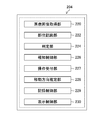
- FIG. 3 is a functional block diagram of the image processing unit.
- FIG. 4 is a diagram showing information recorded in the recording unit.
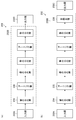
- FIG. 5 is a diagram showing a configuration example of a convolutional neural network.
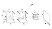
- FIG. 6 is a diagram showing a state of the convolution process by the filter.
- FIG. 7 is a flowchart showing the procedure of the medical image processing method according to the first embodiment.
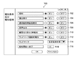
- FIG. 8 is a diagram showing an example of a setting screen of a notification condition and a notification mode.
- FIG. 9 is a diagram showing an example of a method of notifying the determination result.
- FIG. 8 is a diagram showing an example of a setting screen of a notification condition and a notification mode.
- FIG. 10 is another diagram showing an example of a method of notifying the determination result.
- FIG. 11 is still another diagram showing an example of a method of notifying the determination result.
- FIG. 12 is another flowchart showing the procedure of the medical image processing method according to the first embodiment.
- FIG. 13 is still another flowchart showing the procedure of the medical image processing method according to the first embodiment.
- FIG. 1 is an external view of the endoscope system 10 (endoscope system, medical image processing apparatus), and FIG. 2 is a block diagram showing a main configuration of the endoscope system 10.
- the endoscope system 10 includes an endoscope scope 100 (medical image acquisition unit, endoscope scope) and a processor 200 (medical image processing device, processor, medical image acquisition unit, site recognition). It is composed of a unit, a determination unit, a notification unit, a notification control unit, an operation reception unit, a moving direction estimation unit), a light source device 300 (light source device), and a monitor 400 (display device, display).
- the endoscope scope 100 includes a hand operation unit 102 and an insertion unit 104 connected to the hand operation unit 102.
- the operator grasps and operates the hand operation unit 102, inserts the insertion unit 104 into the body of the subject (living body), and observes it.
- the hand operation unit 102 is provided with an air supply / water supply button 141, a suction button 142, a function button 143 to which various functions are assigned, and a shooting button 144 for receiving a shooting instruction operation (still image, moving image). ..
- the insertion portion 104 is composed of a soft portion 112, a curved portion 114, and a tip hard portion 116 in this order from the hand operation portion 102 side.
- the curved portion 114 is connected to the base end side of the hard tip portion 116, and the soft portion 112 is connected to the base end side of the curved portion 114.
- the hand operation unit 102 is connected to the base end side of the insertion unit 104. The user can bend the curved portion 114 and change the direction of the hard tip portion 116 up, down, left and right by operating the hand operating portion 102.
- the tip rigid portion 116 is provided with a photographing optical system 130, an illumination portion 123, a forceps opening 126, and the like (see FIGS. 1 and 2).
- white light and / or narrow band light (red narrow band light, green narrow band light, etc.) are transmitted from the illumination lenses 123A and 123B of the illumination unit 123.
- narrow band light red narrow band light, green narrow band light, etc.
- One or more of blue narrow band light and purple narrow band light can be irradiated.
- cleaning water is discharged from a water supply nozzle (not shown) to clean the photographing lens 132 (photographing lens, photographing unit) of the photographing optical system 130 and the illumination lenses 123A and 123B. Can be done.
- a conduit (not shown) communicates with the forceps opening 126 opened by the hard tip 116, and a treatment tool (not shown) for removing a tumor or the like is inserted into this conduit, and the patient moves back and forth as appropriate to the subject. You can take the necessary measures.
- a photographing lens 132 (photographing portion) is arranged on the tip end surface 116A of the tip rigid portion 116.
- a CMOS (Complementary Metal-Oxide Semiconductor) type image sensor 134 image sensor, image acquisition unit), drive circuit 136, and AFE138 (AFE: Analog Front End, imaging unit) are arranged behind the photographing lens 132.
- An image signal is output by these elements.
- the image pickup element 134 is a color image pickup element, and is composed of a plurality of light receiving elements arranged in a matrix (two-dimensional arrangement) in a specific pattern arrangement (Bayer arrangement, X-Trans (registered trademark) arrangement, honeycomb arrangement, etc.). It has a plurality of pixels.
- Each pixel of the image sensor 134 includes a microlens, a red (R), green (G), or blue (B) color filter and a photoelectric conversion unit (photodiode or the like).
- the photographing optical system 130 can also generate a color image from pixel signals of three colors of red, green, and blue, and generate an image from pixel signals of any one or two colors of red, green, and blue. You can also do it.
- the image sensor 134 may be a CCD (Charge Coupled Device) type. Further, each pixel of the image sensor 134 may further include a purple color filter corresponding to a purple light source 310V and / or an infrared filter corresponding to an infrared light source.
- the optical image of the subject is imaged on the light receiving surface (imaging surface) of the image sensor 134 by the photographing lens 132, converted into an electric signal, output to the processor 200 via a signal cable (not shown), and converted into a video signal.
- a signal cable not shown
- a video signal not shown
- the illumination lenses 123A and 123B of the illumination portion 123 are provided adjacent to the photographing lens 132.
- the ejection ends of the light guide 170 which will be described later, are arranged behind the illumination lenses 123A and 123B, and the light guide 170 is inserted into the insertion portion 104, the hand operation portion 102, and the universal cable 106 to form the light guide 170.
- the incident end is arranged within the light guide connector 108.
- the user performs imaging at a predetermined frame rate while inserting or removing the endoscope scope 100 (insertion unit 104) having the above-described configuration into the living body as the subject (under the control of the medical image acquisition unit 220). By doing so, it is possible to sequentially take time-series images in the living body.
- the light source device 300 includes a light source 310 for illumination, a diaphragm 330, a condenser lens 340, a light source control unit 350, and the like, and causes observation light to enter the light guide 170.
- the light source 310 includes a red light source 310R, a green light source 310G, a blue light source 310B, and a purple light source 310V that irradiate narrow band light of red, green, blue, and purple, respectively, and is narrow in red, green, blue, and purple. It can irradiate band light.
- the illuminance of the observation light by the light source 310 is controlled by the light source control unit 350, and the illuminance of the observation light can be changed (increased or decreased) and the illumination can be stopped as needed.
- the light source 310 can emit red, green, blue, and purple narrow-band light in any combination.
- narrow-band light of red, green, blue, and purple can be emitted at the same time to irradiate white light (normal light) as observation light, or one or two of them can be emitted to emit narrow-band light. It is also possible to irradiate light (special light).
- the light source 310 may further include an infrared light source that irradiates infrared light (an example of narrow band light).
- white light or narrow band light may be irradiated as observation light by a light source that irradiates white light and a filter that transmits white light and each narrow band light.
- the light source 310 may be a light source having a white band or a light source having a plurality of wavelength bands as the light having a white band, or a light source having a specific wavelength band narrower than the white wavelength band.
- the specific wavelength band may be a blue band or a green band in the visible region, or a red band in the visible region.
- a specific wavelength band is a visible blue band or green band, it includes a wavelength band of 390 nm or more and 450 nm or less, or 530 nm or more and 550 nm or less, and peaks in a wavelength band of 390 nm or more and 450 nm or less or 530 nm or more and 550 nm or less. It may have a wavelength.
- the light in the specific wavelength band includes the wavelength band of 585 nm or more and 615 nm or less, or 610 nm or more and 730 nm or less, and the light in the specific wavelength band is 585 nm or more and 615 nm or less or 610 nm or more. It may have a peak wavelength in the wavelength band of 730 nm or less.
- the specific wavelength band includes a wavelength band of 400 ⁇ 10 nm, 440 ⁇ 10 nm, 470 ⁇ 10 nm, or 600 nm or more and 750 nm, and 400 ⁇ 10 nm, 440 ⁇ 10 nm, 470 ⁇ 10 nm, or 600 nm or more and 750 nm. It may have a peak wavelength in the following wavelength band.
- the light generated by the light source 310 may include a wavelength band of 790 nm or more and 820 nm or less, or 905 nm or more and 970 nm or less, and may have a peak wavelength in a wavelength band of 790 nm or more and 820 nm or less or 905 nm or more and 970 nm or less.
- the light source 310 may include a light source that irradiates excitation light having a peak of 390 nm or more and 470 nm or less.
- a medical image medical image, in-vivo image
- a dye for the fluorescence method fluorestin, acridine orange, etc.
- the light source type (laser light source, xenon light source, LED light source (LED: Light-Emitting Diode), etc.), wavelength, presence / absence of filter, etc. of the light source 310 are preferably configured according to the type of subject, the part, the purpose of observation, and the like.
- switching the wavelength for example, by rotating a disk-shaped filter (rotary color filter) arranged in front of the light source and provided with a filter that transmits or blocks light of a specific wavelength, the wavelength of the emitted light is switched. May be good.
- the image sensor used in carrying out the present invention is not limited to the color image sensor in which the color filter is arranged for each pixel like the image sensor 134, and may be a monochrome image sensor.
- the wavelength of the observation light can be sequentially switched to perform surface-sequential (color-sequential) imaging.
- the wavelength of the emitted observation light may be sequentially switched between (purple, blue, green, red), or a rotary color filter (red, green, blue, purple, etc.) is irradiated with broadband light (white light). You may switch the wavelength of the observation light emitted by.
- the wavelength of the observation light emitted by the rotary color filter (green, blue, purple, etc.) by irradiating one or a plurality of narrow band lights (green, blue, purple, etc.) may be switched.
- the narrow-band light may be infrared light having two or more wavelengths (first narrow-band light, second narrow-band light) having different wavelengths.
- the observation light emitted from the light source device 300 is transmitted to the illumination lenses 123A and 123B via the light guide 170, and the illumination lens
- the observation range is irradiated from 123A and 123B.
- the configuration of the processor 200 will be described with reference to FIG.
- the processor 200 inputs the image signal output from the endoscope scope 100 via the image input controller 202, performs necessary image processing in the image processing unit 204 (medical image processing unit, processor), and performs necessary image processing in the video output unit 206. Output via.
- the observation image (in-vivo image) is displayed on the monitor 400 (display device).
- CPU Central Processing Unit
- the communication control unit 205 controls communication with respect to the acquisition of medical images, etc. between an in-hospital system (HIS: Hospital Information System), an in-hospital LAN (Local Area Network), and / or an external system or network (not shown). I do.
- FIG. 3 is a functional block diagram of the image processing unit 204.
- the image processing unit 204 includes a medical image acquisition unit 220 (medical image acquisition unit, image acquisition unit), a site recognition unit 222 (site recognition unit), a determination unit 224 (determination unit), and a notification control unit 226 (notification control unit). ),
- the operation reception unit 227 operation reception unit
- the movement direction estimation unit 228 movement direction estimation unit
- the recording control unit 229 recording control unit
- display control unit 230 display control unit
- the image processing unit 204 uses the above-mentioned functions to calculate the feature amount of the medical image, process to emphasize or reduce the components of a specific frequency band, and emphasize or emphasize a specific target (area of interest, blood vessel of desired depth, etc.). It is possible to perform processing that makes it inconspicuous.
- the image processing unit 204 acquires special light having information in a specific wavelength band based on a normal light image obtained by irradiating light in a white band or light in a plurality of wavelength bands as light in the white band.
- An image acquisition unit may be provided.
- the signal of a specific wavelength band is used for RGB (R: red, G: green, B: blue) or CMY (C: cyan, M: magenta, Y: yellow) color information included in a normal optical image. It can be obtained by the calculation based on.
- the image processing unit 204 includes a normal light image obtained by irradiating light in a white band or light in a plurality of wavelength bands as light in the white band, and a special light image obtained by irradiating light in a specific wavelength band.
- a feature amount image generation unit that generates a feature amount image by an operation based on at least one of the above may be provided, and a feature amount image as a medical image (medical image) may be acquired and displayed. The above-mentioned processing is performed under the control of the CPU 210.
- Various processors include, for example, a CPU (Central Processing Unit), which is a general-purpose processor that executes software (programs) to realize various functions.
- the various processors described above include programmable logic devices (PLCs) such as GPUs (Graphics Processing Units) and FPGAs (Field Programmable Gate Arrays), which are specialized processors for image processing, whose circuit configurations can be changed after manufacturing.
- PLCs programmable logic devices
- GPUs Graphics Processing Units
- FPGAs Field Programmable Gate Arrays
- PLD Programmable Logic Device
- the above-mentioned various processors also include a dedicated electric circuit, which is a processor having a circuit configuration specially designed for executing a specific process such as an ASIC (Application Specific Integrated Circuit).
- each part may be realized by one processor, or may be realized by a plurality of processors of the same type or different types (for example, a plurality of FPGAs, or a combination of a CPU and an FPGA, or a combination of a CPU and a GPU). Further, a plurality of functions may be realized by one processor. As an example of configuring a plurality of functions with one processor, first, as represented by a computer, one processor is configured by a combination of one or more CPUs and software, and this processor is used as a plurality of functions. There is a form to be realized.
- SoC System On Chip
- a processor that realizes the functions of the entire system with one IC (Integrated Circuit) chip
- various functions are configured by using one or more of the above-mentioned various processors as a hardware structure.
- the hardware structure of these various processors is, more specifically, an electric circuit (circuitry) in which circuit elements such as semiconductor elements are combined.
- These electric circuits may be electric circuits that realize the above-mentioned functions by using logical sum, logical product, logical denial, exclusive logical sum, and logical operations combining these.
- the processor or electric circuit executes software (program), it can be read by a computer of the software (for example, various processors and electric circuits constituting the image processing unit 204, and / or a combination thereof).
- the code is stored in a non-temporary recording medium such as ROM 211 (ROM: Read Only Memory), and the computer refers to the software.
- the software stored in the non-temporary recording medium is a program for executing the operation method of the medical image processing apparatus according to the present invention and data used for execution (data related to acquisition of medical images, notification conditions, and notification modes). Includes data used for identification, parameters used in the recognition unit, etc.).
- the code may be recorded on a non-temporary recording medium such as various optical magnetic recording devices or semiconductor memories instead of the ROM 211.
- a non-temporary recording medium such as various optical magnetic recording devices or semiconductor memories instead of the ROM 211.
- RAM212 RAM: Random Access Memory
- EEPROM Electrically Erasable and Programmable Read Only Memory
- the recording unit 207 may be used as the “non-temporary recording medium”.
- the ROM 211 (ROM: Read Only Memory) is a non-volatile storage element (non-temporary recording medium), and various image processing methods (including the operation method of the medical image processing device according to the present invention) are used in the CPU 210 and /. Alternatively, a computer-readable code of a program to be executed by the image processing unit 204 (computer) is stored.
- the RAM 212 (RAM: Random Access Memory) is a storage element for temporary storage during various processes, and can also be used as a buffer for image acquisition.
- the voice processing unit 209 outputs a message (voice) related to medical image processing, site recognition, notification, etc. from the speaker 209A (notification unit, speaker) under the control of the CPU 210 and the image processing unit 204.
- the operation unit 208 can be configured by a device such as a keyboard and a mouse (not shown), and the user can instruct the execution of medical image processing via the operation unit 208 (operation reception unit) and conditions necessary for execution (for example, which will be described later). Notification conditions and notification mode settings) can be specified.
- the operation via the operation unit 208 includes setting of notification conditions and notification modes (see FIG. 8), and operations indicating that acquisition of medical images of a plurality of parts to be imaged has been completed.
- the operation reception unit 227 described above receives a user's operation via the operation unit 208, and processing is performed by each unit of the CPU 210 and the image processing unit 204 according to the received operation.
- the recording unit 207 (recording device, memory, non-temporary recording medium) has an endoscopic image 260 (endoscopic image, medical image, medical image) and site information 262 (site information; subject). (Information indicating a plurality of parts to be photographed), part recognition result 264 (recognition result of a part of a subject shown in a medical image), judgment result 266 (a part of a plurality of parts to be photographed that has not been photographed). Judgment result) etc. are recorded.
- the site information 262 may be in the form of an image, or may be in the form of a list composed of letters and numbers (for example, "chest esophagus 1", “middle body B", “lesser curvature side of the angular incisure") and the like. It may be in the form.
- the site recognition unit 222 can be configured by using a trained model such as a neural network (a model trained using an image set composed of images of a living body).
- a trained model such as a neural network (a model trained using an image set composed of images of a living body).
- a CNN Convolutional Neural Network
- FIG. 5 is a diagram showing the configuration of CNN232 (neural network).
- the CNN 232 has an input layer 232A (input unit), an intermediate layer 232B, and an output layer 232C.
- the input layer 232A inputs an endoscopic image (medical image) acquired by the medical image acquisition unit 220 and outputs a feature amount.
- the intermediate layer 232B includes the convolution layer 234 and the pooling layer 235, and the feature amount output by the input layer 232A is input to calculate other feature amounts.
- These layers have a structure in which a plurality of "nodes” are connected by “edges”, and the weighting coefficient applied to the input image is associated with the node and the edge and stored in a weighting coefficient storage unit (not shown). It is remembered. The value of the weighting factor changes as the learning progresses.
- the intermediate layer 232B calculates the feature amount by the convolution calculation and the pooling process.
- the convolution operation performed in the convolution layer 234 is a process of acquiring a feature map by a convolution operation using a filter, and plays a role of feature extraction such as edge extraction from an image. By the convolution operation using this filter, one channel (one sheet) of "feature map” is generated for one filter. The size of the "feature map”, if downscaled by convolution, becomes smaller as each layer is convolved.
- the pooling process performed in the pooling layer 235 is a process of reducing (or enlarging) the feature map output by the convolution operation to make a new feature map, so that the extracted features are not affected by translation or the like. Plays the role of giving robustness to.
- the intermediate layer 232B can be composed of one or a plurality of layers that perform these processes.
- the CNN232 may be configured without the pooling layer 235.
- CNN232 may include a fully bonded layer 236 as in the example shown in part (b) of FIG.
- the layer structure of CNN232 is not limited to the case where the convolution layer 234 and the pooling layer 235 are repeated one by one, and any one layer (for example, the convolution layer 234) may be continuously included.
- FIG. 6 is a schematic view showing a configuration example of the intermediate layer 232B of the CNN 232 shown in FIG.
- the convolution layer of the first intermediate layer 232B (1 th) an image set including a plurality of medical images convolution (time learning training image set, at sites recognized image set for site recognition) and the filter F 1 The operation is performed.
- the image set is composed of N images (N channels) having an image size of H in the vertical direction and W in the horizontal direction.
- the images constituting the image set are three-channel images of R (red), G (green), and B (blue).
- the filter size is 5 ⁇ 5 ⁇ N.
- the filter F 2 used in the second convolution layer has a filter size of 3 ⁇ 3 ⁇ M, for example, in the case of a size 3 (3 ⁇ 3) filter.
- the second to nth convolution layers perform convolution operations using filters F 2 to F n.
- the size of the "feature map" in the nth convolution layer is smaller than the size of the "feature map” in the second convolution layer because it is downscaled by the convolution layer or pooling layer up to the previous stage. Is.
- lower-order feature extraction (edge extraction, etc.) is performed in the convolution layer closer to the input side, and higher-order feature extraction (features related to the shape, structure, etc. of the recognition target) is performed as the intermediate layer 232B approaches the output side. Extraction) is performed.
- the intermediate layer 232B may include a layer for batch normalization in addition to the convolution layer 234 and the pooling layer 235.
- the batch normalization process is a process of normalizing the distribution of data in units of mini-batch when learning, and plays a role of advancing learning quickly, reducing dependence on initial values, suppressing overfitting, and the like.
- the output layer 232C outputs the feature amount calculated by the intermediate layer 232B in a format suitable for site recognition.
- the output layer 232C may include a fully connected layer.
- FIG. 7 is a flowchart showing an outline of processing of the medical image processing method (operation method of the medical image processing device) according to the first embodiment. It is assumed that the learning of CNN232 using the learning data has been executed.
- the image processing unit 204 (notification control unit 226) sets the notification condition and the notification mode according to the user's operation via the operation unit 208 (step S100: notification condition setting step, notification mode setting step).
- the user can perform the setting operation via the screen 700 (displayed on the monitor 400) illustrated in FIG.
- the screen 700 has areas 702 to 712 in which radio buttons are arranged, areas 714 in which pull-down menus are arranged, and areas 716 in which numerical input fields are arranged.
- the user can set whether or not to perform the notification (on or off; area 702) by operating the radio button.
- the user operates the radio button to display "whether or not to perform notification” (area 702), "whether or not to perform notification by screen display” (area 704), and “display the notification screen in the initial state”. "Whether or not” (Region 706; see the examples of FIGS. 10 and 11), "Whether or not to perform notification by voice output (voice signal)" (Region 708).
- the user can operate the radio button to "whether or not to notify at the timing when the organ of the subject shown in the medical image is switched" (area 710) and "a predetermined part (so-called” landmark "). Whether or not to give notification at the timing when the medical image of the subject in ") is taken” (region 712) can be set.
- the radio button of the area 712 is turned on, the user can select a part to be a landmark by operating the pull-down menu of the area 714.
- “esophaogastric junction (EGJ)” is selected as the landmark, but the landmark may be another site (for example, pharynx).
- timing at which the organ of the subject shown in the medical image is switched and “timing at which the medical image of the subject is taken at a predetermined portion” are the “expected end timing” (plurality to be captured) in the present invention. This is an example of (timing when it is expected that the acquisition of medical images for the site) is completed.
- the user sets "the elapsed time from the start to the end of the notification (from the switching from the notification state to the non-notification state)" ("predetermined time") by inputting the numerical value in the area 716. can do.
- the notification control unit 226 switches the notification by the monitor 400 and / or the speaker 209A from the notification state to the non-notification state (stops or ends the notification) after the time (seconds) input to the area 716 has elapsed. In the example of FIG. 8, it takes 1.0 seconds from the start to the end of the notification.
- Numerical value input may be a method of selecting a predetermined numerical value from a pull-down menu.
- the notification control unit 226 may reduce (reduce) the notification power after the lapse of a designated time.
- the user can set the notification condition and the notification mode as needed, and the notification control unit 226 notifies (supports) according to the setting contents. ), Excessive notification can be suppressed.
- the above example is an example of setting, and other items (notification by light or vibration, etc.) may be set.
- the notification condition and the notification mode may be set not only at the start of the medical image processing but also at an arbitrary timing during the processing.
- the endoscopy system 10 may automatically set the notification conditions and the notification mode without the user's operation.
- the medical image acquisition unit 220 acquires a time-series endoscopic image (medical image) (step S110: image acquisition step).
- the medical image acquisition unit 220 may acquire an endoscopic image taken by the endoscope scope 100, or may acquire an endoscopic image 260 recorded by the recording unit 207.
- the recording control unit 229 can record the acquired image as an endoscopic image 260 in the recording unit 207.
- the part recognition unit 222 (part recognition unit, processor) recognizes the part (photographed part) of the subject in the endoscopic image acquired in step S110 by using the above-mentioned CNN232 (step S120: part). Recognition process).
- the site include the cervical esophagus, the thoracic esophagus, and the abdominal esophagus in the case of the esophagus.
- the thoracic esophagus may be further divided into an upper thoracic esophagus, a middle thoracic esophagus, and a lower thoracic esophagus.
- the cardia, the pylorus (fundus), the body of the stomach, the angular incisure, the antrum, the anterior pylorus, and the pylorus ring can be mentioned.
- the body of the stomach may be further divided into upper, middle and lower parts. Further, the circumferential direction may be divided into the lesser curvature, the front wall, the greater curvature, and the rear wall.
- the site recognition unit 222 indicates that the specific subject is in a predetermined area of the endoscopic image (for example,). , Center), a specific subject is reflected in the endoscopic image with a size larger than the specified size, and a specific subject is more than the specified degree of focus in the endoscopic image. If at least one of them is satisfied, it may be determined that the site has been recognized.
- the recording control unit 229 records the imaged portion information (site recognition result) as the site recognition result 264 in the recording unit 207 (step S130: recognition result recording step).
- the recording control unit 229 preferably records the site recognition result in association with the endoscopic image.
- the recording control unit 229 may record the site recognition result in the above-mentioned list format.
- the determination unit 224 compares the part recognized in step S130 (part recognition result 264) with the part indicated by the part information 262, and among a plurality of parts to be photographed, the part not photographed (the unphotographed part). (Step S140: determination step).
- the determination unit 224 can determine, for example, the presence or absence of an unphotographed portion and / or which portion has not been imaged.
- the determination unit 224 may make a determination every time one or a plurality of images are acquired, or may make a determination every time a designated time elapses.
- the notification control unit 226 determines whether or not the expected end timing, which is expected to complete the acquisition of endoscopic images (medical images) for a plurality of parts to be imaged, has arrived (step S150: notification step). ).
- the timing at which the site to be observed changes from one organ to another organ in the recognition result (for example, the timing when the esophagus changes to the stomach; set in region 710 in the example of FIG. 8), a predetermined site.
- the timing at which the medical image of the subject in the above image is acquired (the timing at which the image of the landmark is acquired; set in the areas 712 and 714 in the example of FIG. 8) can be set as the expected end timing.
- the timing at which the user's operation indicating the end of shooting for the determined range is accepted (the timing at which the operation reception unit 227 accepts the user's operation via the operation unit 208), that is, the user "shooting is completed”.
- the timing recognized as “expected end timing” may be used.
- the notification control unit 226 may determine the arrival of the expected end timing based on the number of shots determined and the expiration of the shooting time. In the "expected end timing", it is sufficient if the acquisition of the endoscopic image is expected to be completed (if there is a possibility), and the acquisition does not have to be actually completed.
- the moving direction estimation unit 228 (moving direction estimating unit) estimates the moving direction (insertion or removal) of the endoscope scope 100 based on, for example, the movement vector of the subject, and the moving direction is removed from the insertion (forward direction) (moving direction).
- the timing that changes in the backward direction) may be set as the "expected end timing”.
- the timing at which the user reverses the direction of the tip portion of the endoscope scope 100 and performs so-called “looking up” (the timing at which the endoscope scope 100 appears in the endoscope image) is set as the "expected end timing". May be good.
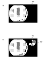
- FIG. 9 is a diagram showing an example of notification about the stomach.
- the part (a) in FIG. 9 is a diagram showing a state before the start of observation (all parts have not been observed), and in the image 800 showing a schema diagram (schematic diagram) of the stomach, the entire region is not colored (shaded). be.
- the part (b) in the figure is a diagram showing the notification state at the expected end timing, and the parts observed in the image 802 (the lesser curvature part, the body of the stomach, the vestibule part, the anterior part of the pylorus, The gastric corpus pyloric side) is displayed in color, and the unobserved part (angular incisure lesser curvature side) is uncolored.
- a symbol (circle 804) surrounding an unobserved part is attached.
- the schema diagram of the organ esophagus, stomach, etc.
- the notification control unit 226 may color the schema diagram during normal observation and leave the observed portion uncolored (or lighten the color) at the time of notification. Further, the color may be changed between the observed part and the unobserved part, the color may be changed at the timing of notification, or the unobserved part may be blinked.
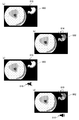
- FIG. 10 is a diagram showing a display example on the monitor 400 (display).
- Part (a) of FIG. 10 shows a state at the time of normal observation (a state in which the expected end timing has not arrived), and only the endoscopic image 810 (normal observation image) is displayed.
- the part (b) in the figure shows the notification state at the expected end timing, and the endoscopic image 812 on which the image 802 (see FIG. 9) showing the unobserved portion is superimposed and displayed is displayed.
- the notification control unit 226 may display the image 802 on a screen different from the endoscopic image.
- the notification control unit 226 newly displays the information (image 802) that was not displayed on the screen before the notification is performed, but in addition to or instead of the screen display. Therefore, the sound that was not output before the notification may be newly output from the speaker 209A.
- the notification control unit 226 outputs a warning sound such as a beep sound when there is an unphotographed part, or a sound indicating an unphotographed part such as "the lesser curvature side of the angular incisure is not photographed" at the time of notification. This makes it possible to notify.
- the user can operate the endoscope scope 100 in response to the notification indicating such unphotographed (observation omission) to image (observe) the unphotographed portion, so that the observation omission can be detected. Can be prevented. Further, since the endoscope system 10 notifies at an appropriate timing (expected end timing), there is no possibility of interfering with the observation.
- the notification control unit 226 colors the schema diagram with the same color, circles the entire schema diagram (when the screen is displayed), and so on. It is preferable to perform notification in a manner different from that when there is an unphotographed part, such as outputting a voice such as "There is no".
- the notification control unit 226 may reduce the notification power (for example, reduce the schema diagram, lower the volume, etc.) as compared with the case where there is an unphotographed portion.
- the CPU 210 and the image processing unit 204 repeat the processes of steps S110 to S160 until the observation is completed (between NO in step S170).
- the medical image processing device As described above, according to the medical image processing device, the operating method of the medical image processing device, and the endoscopic system according to the present invention, it is possible to notify the observation omission at an appropriate timing.
- the stomach schema diagram (image 802) is not superimposed and displayed during normal observation (the screen display during normal observation is off; the radio button is turned off in the area 706 of FIG. 8).
- the schema diagram for example, the image 800 shown in FIG. 9 may be superimposed and displayed even during normal observation (the image display during normal observation is on).
- the notification control unit 226 blinks the image 802 on the screen of the monitor 400 at the time of notification (expected end timing).
- the aspect shown in FIG. 11 is an aspect of notifying by changing the display mode of the information (image 800) already displayed on the screen of the monitor 400 (display).
- the notification control unit 226 may perform notification by changing the output mode of the voice already output from the speaker 209A in addition to or instead of displaying the information on the screen.
- the notification control unit 226 can increase the notification power by changing, for example, the voice output during normal observation and the voice content (message content), volume, pitch, pattern, etc. at the expected end timing. ..
- the part (c) of FIG. 11 shows the state at the time of normal observation (the image 800 is displayed; the icon 816 is marked with a cross and there is no audio output), and the part (d) of the figure shows the state at the time of notification. (Blinking and audio output of image 802; icon 818 is displayed).
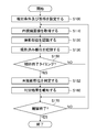
- the unphotographed portion is continuously determined at a timing other than the expected end timing, but as shown in FIG. 12, the determination unit 224 determines the expected end timing (for example, the timing at which the user's instruction is received.
- the determination of the unphotographed portion may be performed at the timing when the observed organ changes or when the landmark image is acquired). Since the flowchart of FIG. 12 is the same as that of FIG. 7 except for step S152, the description of the same portion will be omitted.
- the notification control unit 226 reduces the notification power after a certain period of time has passed from the notification (including the end of the notification). (See Steps S162, S164: Notification Step, Region 716 of FIG. 8).
- ⁇ Modified example of site recognition method> In the first embodiment described above, the case where the site recognition unit 222 performs the site recognition using the CNN has been described, but the site recognition is not limited to the CNN, but the support vector machine (SVM) and the k-nearest neighbor method (A general multi-class classification method based on supervised learning such as k-NN: k-Nearest Neighbor) can be used.
- SVM support vector machine
- k-nearest neighbor method A general multi-class classification method based on supervised learning such as k-NN: k-Nearest Neighbor
- the medical image analysis processing unit detects a region of interest, which is a region of interest, based on the feature amount of pixels of the medical image.
- the medical image analysis result acquisition unit is a medical image processing device that acquires the analysis results of the medical image analysis processing unit.
- the medical image analysis processing unit detects the presence or absence of a noteworthy object based on the feature amount of the pixel of the medical image.
- the medical image analysis result acquisition unit is a medical image processing device that acquires the analysis results of the medical image analysis processing unit.
- the medical image analysis result acquisition department Obtained from a recording device that records the analysis results of medical images
- the analysis result is a medical image processing apparatus that is a region of interest that is a region of interest included in a medical image, a presence or absence of an object of interest, or both.
- a medical image is a medical image processing apparatus that is a normal light image obtained by irradiating light in a white band or light in a plurality of wavelength bands as light in a white band.
- a medical image is an image obtained by irradiating light in a specific wavelength band.
- a medical image processing device in which a specific wavelength band is narrower than the white wavelength band.
- a medical image processing device in which a specific wavelength band is a blue or green band in the visible range.
- a medical treatment in which a specific wavelength band includes a wavelength band of 390 nm or more and 450 nm or less or 530 nm or more and 550 nm or less, and light in a specific wavelength band has a peak wavelength in a wavelength band of 390 nm or more and 450 nm or less or 530 nm or more and 550 nm or less.
- Image processing device
- the specific wavelength band includes a wavelength band of 585 nm or more and 615 nm or less or 610 nm or more and 730 nm or less, and the light of the specific wavelength band has a peak wavelength in the wavelength band of 585 nm or more and 615 nm or less or 610 nm or more and 730 nm or less.
- Image processing device includes a wavelength band of 585 nm or more and 615 nm or less or 610 nm or more and 730 nm or less, and the light of the specific wavelength band has a peak wavelength in the wavelength band of 585 nm or more and 615 nm or less or 610 nm or more and 730 nm or less.
- the specific wavelength band includes a wavelength band in which the extinction coefficient differs between the oxidized hemoglobin and the reduced hemoglobin, and the light in the specific wavelength band has a peak wavelength in the wavelength band having a different extinction coefficient between the oxidized hemoglobin and the reduced hemoglobin.
- Medical image processing device includes a wavelength band in which the extinction coefficient differs between the oxidized hemoglobin and the reduced hemoglobin, and the light in the specific wavelength band has a peak wavelength in the wavelength band having a different extinction coefficient between the oxidized hemoglobin and the reduced hemoglobin.
- the specific wavelength band includes 400 ⁇ 10 nm, 440 ⁇ 10 nm, 470 ⁇ 10 nm, or 600 nm or more and 750 nm or less, and the light in the specific wavelength band is 400 ⁇ 10 nm, 440 ⁇ 10 nm, 470 ⁇ .
- a medical image processing apparatus having a peak wavelength in a wavelength band of 10 nm or 600 nm or more and 750 nm or less.
- a medical image is an in-vivo image that shows the inside of a living body.
- An in-vivo image is a medical image processing device that has information on fluorescence emitted by a fluorescent substance in the living body.
- Fluorescence is a medical image processing device obtained by irradiating a living body with excitation light having a peak of 390 or more and 470 nm or less.
- a medical image is an in-vivo image that shows the inside of a living body.
- a specific wavelength band is a medical image processing device that is a wavelength band of infrared light.
- a medical image in which a specific wavelength band includes a wavelength band of 790 nm or more and 820 nm or less or 905 nm or more and 970 nm or less, and light in a specific wavelength band has a peak wavelength in a wavelength band of 790 nm or more and 820 nm or less or 905 nm or more and 970 nm or less. Processing equipment.
- the medical image acquisition unit acquires a special optical image having information in a specific wavelength band based on a normal light image obtained by irradiating light in a white band or light in a plurality of wavelength bands as light in the white band. Equipped with an optical image acquisition unit
- the medical image is a medical image processing device that is a special optical image.
- Appendix 17 A medical image processing device that obtains a signal in a specific wavelength band by calculation based on RGB or CMY color information included in a normal optical image.
- Appendix 18 By calculation based on at least one of a normal light image obtained by irradiating light in a white band or light in a plurality of wavelength bands as light in a white band and a special light image obtained by irradiating light in a specific wavelength band. Equipped with a feature amount image generator that generates a feature amount image A medical image is a medical image processing device that is a feature image.
Abstract
The purpose of the present invention is to provide a medical image processing device that can provide notification of an observation omission at an appropriate timing, a method for operating the medical image processing device, and an endoscope system. A medical image processing device according to one aspect of the present invention is provided with: memory in which is stored site information indicating a predetermined site of a subject that should be photographed; a processor; and a notification unit. The processor acquires a medical image of the subject, recognizes the site of the subject that was photographed in the medical image, compares the recognized site and the site indicated by the site information, determines, from among sites that are to be photographed, a site that was not photographed, and provides notification, through the notification unit, of the determination result at an anticipated ending timing at which it is anticipated that acquisition of medical images of the sites that should be photographed will end.
Description
本発明は医療画像処理装置、医療画像処理装置の作動方法、及び内視鏡システムに関する。
The present invention relates to a medical image processing device, an operating method of the medical image processing device, and an endoscopic system.
特許文献1に記載された画像表示装置では、内視鏡画像から解剖学的ランドマークを含むランドマーク画像を検出する。さらに、撮影対象臓器に対応した仮想モデルのランドマーク部分にランドマーク画像を割り当て、複数の内視鏡画像を相互の接続関係を利用して仮想モデルの対応部分にそれぞれ割り当てるマッピングを行う。複数の内視鏡画像が各部に割り当てられた仮想モデルに基づき、撮影対象臓器の既撮影領域及び未撮影領域を表すマップ画像を生成してモニタに表示させる。
The image display device described in Patent Document 1 detects a landmark image including an anatomical landmark from an endoscopic image. Further, a landmark image is assigned to the landmark portion of the virtual model corresponding to the organ to be imaged, and mapping is performed in which a plurality of endoscopic images are assigned to the corresponding portion of the virtual model by utilizing the mutual connection relationship. Based on a virtual model in which a plurality of endoscopic images are assigned to each part, a map image showing a photographed area and an unphotographed area of an organ to be imaged is generated and displayed on a monitor.
病変の有無を診断するスクリーニング内視鏡のうち、特に上部内視鏡では観察部位が多数に渡り、手技も難しいため、内視鏡診断に不慣れなユーザ(医師)では観察漏れが発生するという問題がある。本問題に対して、「観察済みの部位を自動判定する技術を用いることで、観察忘れを防止する」という方法が考えられるが、観察部位を常に報知すると診断の妨げになるという問題がある。しかしながら、特許文献1のような従来の技術は、撮影漏れの評価は行っているものの、評価結果を適切なタイミングで報知するものではなかった。
Of the screening endoscopes that diagnose the presence or absence of lesions, especially the upper endoscope has many observation sites and the procedure is difficult, so there is a problem that observation omissions occur for users (doctors) who are unfamiliar with endoscopic diagnosis. There is. To solve this problem, a method of "preventing forgetting to observe by using a technique for automatically determining an observed part" can be considered, but there is a problem that the diagnosis is hindered if the observed part is constantly notified. However, although the conventional technique such as Patent Document 1 evaluates the omission of photography, it does not notify the evaluation result at an appropriate timing.
本発明はこのような事情に鑑みてなされたもので、観察漏れを適切なタイミングで報知することができる医療画像処理装置、医療画像処理装置の作動方法、及び内視鏡システムを提供することを目的とする。
The present invention has been made in view of such circumstances, and provides a medical image processing apparatus capable of notifying an observation omission at an appropriate timing, an operation method of the medical image processing apparatus, and an endoscope system. The purpose.
本発明の第1の態様に係る医療画像処理装置は、あらかじめ決められた、被写体における撮影すべき複数の部位を示す部位情報を記憶するメモリと、プロセッサと、報知部と、を備える医療画像処理装置であって、プロセッサは、被写体の医療画像を取得し、医療画像に写っている被写体の部位を認識し、認識された部位と部位情報が示す部位とを比較して、撮影すべき複数の部位のうちで撮影されていない部位を判定し、撮影すべき複数の部位についての医療画像の取得が終了したことが期待される期待終了タイミングで、判定の結果を報知部により報知する。
The medical image processing apparatus according to the first aspect of the present invention includes a predetermined memory for storing part information indicating a plurality of parts to be imaged in a subject, a processor, and a notification unit. In the device, the processor acquires a medical image of the subject, recognizes the part of the subject reflected in the medical image, compares the recognized part with the part indicated by the part information, and performs a plurality of images to be taken. Among the parts, the part that has not been imaged is determined, and the result of the determination is notified by the notification unit at the expected end timing when it is expected that the acquisition of the medical image for the plurality of parts to be imaged is completed.
第2の態様に係る医療画像処理装置は第1の態様において、プロセッサは、終了を示すユーザの操作を受け付け、操作を受け付けたタイミングを期待終了タイミングとして判定の結果を報知する。
In the first aspect, the medical image processing apparatus according to the second aspect receives the user's operation indicating the end, and notifies the result of the determination with the timing of the acceptance of the operation as the expected end timing.
第3の態様に係る医療画像処理装置は第1または第2の態様において、プロセッサは、認識の結果において観察対象である部位が一の臓器から他の臓器に変わったタイミングを期待終了タイミングとして判定の結果を報知する。
In the first or second aspect of the medical image processing apparatus according to the third aspect, the processor determines as the expected end timing the timing at which the part to be observed changes from one organ to another organ in the recognition result. Notify the result of.
第4の態様に係る医療画像処理装置は第1から第3の態様のいずれか1つにおいて、プロセッサは、あらかじめ決められた部位における被写体の医療画像が取得されたタイミングを期待終了タイミングとして判定の結果を報知する。
The medical image processing apparatus according to the fourth aspect is one of the first to third aspects, and the processor determines the timing at which the medical image of the subject at a predetermined portion is acquired as the expected end timing. Notify the result.
第5の態様に係る医療画像処理装置は第4の態様において、あらかじめ決められた部位は食道胃接合部である。
In the fourth aspect of the medical image processing apparatus according to the fifth aspect, the predetermined site is the esophagogastric junction.
第6の態様に係る医療画像処理装置は第4の態様において、あらかじめ決められた部位は咽頭である。
In the fourth aspect of the medical image processing apparatus according to the sixth aspect, the predetermined site is the pharynx.
第7の態様に係る医療画像処理装置は第4から第6の態様のいずれか1つにおいて、プロセッサは、あらかじめ決められた部位における医療画像が取得されたタイミングで判定を行う。
The medical image processing apparatus according to the seventh aspect is one of the fourth to sixth aspects, and the processor makes a determination at the timing when the medical image at a predetermined site is acquired.
第8の態様に係る医療画像処理装置は第1から第7の態様のいずれか1つにおいて、プロセッサは、報知を行った後、あらかじめ指定された時間が経過したら報知の報知力を低下させる。
In any one of the first to seventh aspects of the medical image processing apparatus according to the eighth aspect, the processor reduces the notification power of the notification when a predetermined time elapses after the notification is performed.
第9の態様に係る医療画像処理装置は第8の態様において、報知部は情報を画面表示するディスプレイ及び/または音声を出力するスピーカを備える。
In the eighth aspect, the medical image processing apparatus according to the ninth aspect includes a display for displaying information on the screen and / or a speaker for outputting sound.
第10の態様に係る医療画像処理装置は第9の態様において、プロセッサは、既にディスプレイに画面表示されている情報の表示態様及び/または既にスピーカから出力されている音声の出力態様を変更することにより報知を行う。
In the ninth aspect of the medical image processing apparatus according to the tenth aspect, the processor changes the display mode of the information already displayed on the screen and / or the output mode of the sound already output from the speaker. Notify by.
第11の態様に係る医療画像処理装置は第9または第10の態様において、プロセッサは、報知を行う前に画面表示がされていなかった情報をディスプレイに新たに画面表示させることにより、及び/または報知を開始する前に出力がされていなかった音声をスピーカに新たに出力させることにより報知を行う。
In the ninth or tenth aspect of the medical image processing apparatus according to the eleventh aspect, the processor causes the display to newly display the information that was not displayed on the screen before the notification, and / or Notification is performed by causing the speaker to newly output the sound that was not output before the notification is started.
第12の態様に係る医療画像処理装置は第9から第11の態様のいずれか1つにおいて、プロセッサは、ディスプレイによる画面表示の報知力を増大または低減させる。
In any one of the ninth to eleventh aspects of the medical image processing apparatus according to the twelfth aspect, the processor increases or decreases the notification power of the screen display by the display.
第13の態様に係る医療画像処理装置は第1から第12の態様のいずれか1つにおいて、プロセッサは、被写体が決められた時間以上継続して医療画像に写っている、被写体が医療画像の決められた領域に写っている、及び被写体が医療画像において決められた合焦度合い以上である、のうち少なくとも1つを満たす場合に部位を認識したと判断する。
In any one of the first to twelfth aspects of the medical image processing apparatus according to the thirteenth aspect, the processor continuously captures the subject in the medical image for a predetermined time or longer, and the subject is a medical image. It is determined that the site is recognized when the image is reflected in the determined area and the subject satisfies at least one of the determined in-focus degree or more in the medical image.
本発明の第14の態様に係る医療画像処理装置の作動方法は、あらかじめ決められた、被写体における撮影すべき複数の部位を示す部位情報を記憶するメモリと、プロセッサと、報知部と、を備える医療画像処理装置の作動方法であって、プロセッサは、被写体の医療画像を取得する画像取得工程と、医療画像に写っている被写体の部位を認識する部位認識工程と、認識された部位と部位情報が示す部位とを比較して、撮影すべき複数の部位のうちで撮影されていない部位を判定する判定工程と、撮影すべき複数の部位についての医療画像の取得が終了したことが期待される期待終了タイミングで、判定の結果を報知部により報知する報知工程と、を実行する。
The method of operating the medical image processing apparatus according to the fourteenth aspect of the present invention includes a predetermined memory for storing site information indicating a plurality of sites to be imaged in the subject, a processor, and a notification unit. In the operation method of the medical image processing device, the processor has an image acquisition step of acquiring a medical image of the subject, a part recognition process of recognizing a part of the subject reflected in the medical image, and the recognized part and part information. It is expected that the determination step of determining the non-photographed part among the plurality of parts to be imaged and the acquisition of the medical image for the plurality of parts to be imaged have been completed by comparing with the part indicated by. At the expected end timing, the notification step of notifying the determination result by the notification unit is executed.
なお、第14の態様に係る作動方法は、第2~第13の態様と同様の構成をさらに備えていてもよい。また、本発明に係る作動方法をコンピュータに実行させるプログラム、及び斯かるプログラムのコンピュータ読み取り可能なコードが記録された非一時的記録媒体も、本発明の態様として挙げることができる。
The operation method according to the fourteenth aspect may further include the same configuration as the second to thirteenth aspects. Further, a program for causing a computer to execute the operation method according to the present invention, and a non-temporary recording medium on which a computer-readable code of such a program is recorded can also be mentioned as an aspect of the present invention.
本発明の第15の態様に係る内視鏡システムは、第1から第13の態様のいずれか1つに係る医療画像処理装置と、被写体としての被検体に挿入され医療画像を撮像する内視鏡スコープと、を備え、プロセッサは内視鏡スコープが撮像した医療画像を取得する。
The endoscope system according to the fifteenth aspect of the present invention includes the medical image processing apparatus according to any one of the first to thirteenth aspects and endoscopy inserted into a subject as a subject to capture a medical image. It is equipped with a mirror scope, and the processor acquires medical images captured by the endoscopic scope.
第16の態様に係る内視鏡システムは第15の態様において、プロセッサは、内視鏡スコープの移動方向を推定し、推定した移動方向が後退方向に変化したタイミングを期待終了タイミングとして判定の結果を報知させる。
In the fifteenth aspect of the endoscope system according to the sixteenth aspect, the processor estimates the moving direction of the endoscope scope, and the timing at which the estimated moving direction changes in the backward direction is regarded as the expected end timing as a result of determination. Is notified.
以下、添付図面を参照しつつ、本発明に係る医療画像処理装置、医療画像処理装置の作動方法、及び内視鏡システムの実施形態について詳細に説明する。
Hereinafter, the medical image processing apparatus according to the present invention, the operation method of the medical image processing apparatus, and the embodiment of the endoscope system will be described in detail with reference to the attached drawings.
<第1の実施形態>
<内視鏡システムの構成>
図1は、内視鏡システム10(内視鏡システム、医療画像処理装置)の外観図であり、図2は内視鏡システム10の要部構成を示すブロック図である。図1,2に示すように、内視鏡システム10は、内視鏡スコープ100(医療画像取得部、内視鏡スコープ)、プロセッサ200(医療画像処理装置、プロセッサ、医療画像取得部、部位認識部、判定部、報知部、報知制御部、操作受付部、移動方向推定部)、光源装置300(光源装置)、及びモニタ400(表示装置、ディスプレイ)から構成される。 <First Embodiment>
<Configuration of endoscopy system>
FIG. 1 is an external view of the endoscope system 10 (endoscope system, medical image processing apparatus), and FIG. 2 is a block diagram showing a main configuration of theendoscope system 10. As shown in FIGS. 1 and 2, the endoscope system 10 includes an endoscope scope 100 (medical image acquisition unit, endoscope scope) and a processor 200 (medical image processing device, processor, medical image acquisition unit, site recognition). It is composed of a unit, a determination unit, a notification unit, a notification control unit, an operation reception unit, a moving direction estimation unit), a light source device 300 (light source device), and a monitor 400 (display device, display).
<内視鏡システムの構成>
図1は、内視鏡システム10(内視鏡システム、医療画像処理装置)の外観図であり、図2は内視鏡システム10の要部構成を示すブロック図である。図1,2に示すように、内視鏡システム10は、内視鏡スコープ100(医療画像取得部、内視鏡スコープ)、プロセッサ200(医療画像処理装置、プロセッサ、医療画像取得部、部位認識部、判定部、報知部、報知制御部、操作受付部、移動方向推定部)、光源装置300(光源装置)、及びモニタ400(表示装置、ディスプレイ)から構成される。 <First Embodiment>
<Configuration of endoscopy system>
FIG. 1 is an external view of the endoscope system 10 (endoscope system, medical image processing apparatus), and FIG. 2 is a block diagram showing a main configuration of the
<内視鏡スコープの構成>
内視鏡スコープ100は、手元操作部102と、この手元操作部102に連設される挿入部104とを備える。術者(ユーザ)は手元操作部102を把持して操作し、挿入部104を被検体(生体)の体内に挿入して観察する。また、手元操作部102には送気送水ボタン141、吸引ボタン142、及び各種の機能を割り付けられる機能ボタン143、及び撮影指示操作(静止画像、動画像)を受け付ける撮影ボタン144が設けられている。挿入部104は、手元操作部102側から順に、軟性部112、湾曲部114、先端硬質部116で構成されている。すなわち、先端硬質部116の基端側に湾曲部114が接続され、湾曲部114の基端側に軟性部112が接続される。挿入部104の基端側に手元操作部102が接続される。ユーザは、手元操作部102を操作することにより湾曲部114を湾曲させて先端硬質部116の向きを上下左右に変えることができる。先端硬質部116には、撮影光学系130、照明部123、鉗子口126等が設けられる(図1,2参照)。 <Structure of endoscopic scope>
Theendoscope scope 100 includes a hand operation unit 102 and an insertion unit 104 connected to the hand operation unit 102. The operator (user) grasps and operates the hand operation unit 102, inserts the insertion unit 104 into the body of the subject (living body), and observes it. Further, the hand operation unit 102 is provided with an air supply / water supply button 141, a suction button 142, a function button 143 to which various functions are assigned, and a shooting button 144 for receiving a shooting instruction operation (still image, moving image). .. The insertion portion 104 is composed of a soft portion 112, a curved portion 114, and a tip hard portion 116 in this order from the hand operation portion 102 side. That is, the curved portion 114 is connected to the base end side of the hard tip portion 116, and the soft portion 112 is connected to the base end side of the curved portion 114. The hand operation unit 102 is connected to the base end side of the insertion unit 104. The user can bend the curved portion 114 and change the direction of the hard tip portion 116 up, down, left and right by operating the hand operating portion 102. The tip rigid portion 116 is provided with a photographing optical system 130, an illumination portion 123, a forceps opening 126, and the like (see FIGS. 1 and 2).
内視鏡スコープ100は、手元操作部102と、この手元操作部102に連設される挿入部104とを備える。術者(ユーザ)は手元操作部102を把持して操作し、挿入部104を被検体(生体)の体内に挿入して観察する。また、手元操作部102には送気送水ボタン141、吸引ボタン142、及び各種の機能を割り付けられる機能ボタン143、及び撮影指示操作(静止画像、動画像)を受け付ける撮影ボタン144が設けられている。挿入部104は、手元操作部102側から順に、軟性部112、湾曲部114、先端硬質部116で構成されている。すなわち、先端硬質部116の基端側に湾曲部114が接続され、湾曲部114の基端側に軟性部112が接続される。挿入部104の基端側に手元操作部102が接続される。ユーザは、手元操作部102を操作することにより湾曲部114を湾曲させて先端硬質部116の向きを上下左右に変えることができる。先端硬質部116には、撮影光学系130、照明部123、鉗子口126等が設けられる(図1,2参照)。 <Structure of endoscopic scope>
The
観察、処置の際には、操作部208(図2参照)の操作により、照明部123の照明用レンズ123A,123Bから白色光及び/または狭帯域光(赤色狭帯域光、緑色狭帯域光、青色狭帯域光、及び紫色狭帯域光のうち1つ以上)を照射することができる。また、送気送水ボタン141の操作により図示せぬ送水ノズルから洗浄水が放出されて、撮影光学系130の撮影レンズ132(撮影レンズ、撮影部)、及び照明用レンズ123A,123Bを洗浄することができる。先端硬質部116で開口する鉗子口126には不図示の管路が連通しており、この管路に腫瘍摘出等のための図示せぬ処置具が挿通されて、適宜進退して被検体に必要な処置を施せるようになっている。
During observation and treatment, by operating the operation unit 208 (see FIG. 2), white light and / or narrow band light (red narrow band light, green narrow band light, etc.) are transmitted from the illumination lenses 123A and 123B of the illumination unit 123. One or more of blue narrow band light and purple narrow band light) can be irradiated. Further, by operating the air supply / water supply button 141, cleaning water is discharged from a water supply nozzle (not shown) to clean the photographing lens 132 (photographing lens, photographing unit) of the photographing optical system 130 and the illumination lenses 123A and 123B. Can be done. A conduit (not shown) communicates with the forceps opening 126 opened by the hard tip 116, and a treatment tool (not shown) for removing a tumor or the like is inserted into this conduit, and the patient moves back and forth as appropriate to the subject. You can take the necessary measures.
図1,2に示すように、先端硬質部116の先端側端面116Aには撮影レンズ132(撮影部)が配設されている。撮影レンズ132の奥にはCMOS(Complementary Metal-Oxide Semiconductor)型の撮像素子134(撮像素子、画像取得部)、駆動回路136、AFE138(AFE:Analog Front End、撮影部)が配設されて、これらの要素により画像信号を出力する。撮像素子134はカラー撮像素子であり、特定のパターン配列(ベイヤー配列、X-Trans(登録商標)配列、ハニカム配列等)でマトリクス状に配置(2次元配列)された複数の受光素子により構成される複数の画素を備える。撮像素子134の各画素はマイクロレンズ、赤(R)、緑(G)、または青(B)のカラーフィルタ及び光電変換部(フォトダイオード等)を含んでいる。撮影光学系130は、赤,緑,青の3色の画素信号からカラー画像を生成することもできるし、赤,緑,青のうち任意の1色または2色の画素信号から画像を生成することもできる。なお、撮像素子134はCCD(Charge Coupled Device)型でもよい。また、撮像素子134の各画素は紫色光源310Vに対応した紫色カラーフィルタ、及び/または赤外光源に対応した赤外用フィルタをさらに備えていてもよい。
As shown in FIGS. 1 and 2, a photographing lens 132 (photographing portion) is arranged on the tip end surface 116A of the tip rigid portion 116. A CMOS (Complementary Metal-Oxide Semiconductor) type image sensor 134 (image sensor, image acquisition unit), drive circuit 136, and AFE138 (AFE: Analog Front End, imaging unit) are arranged behind the photographing lens 132. An image signal is output by these elements. The image pickup element 134 is a color image pickup element, and is composed of a plurality of light receiving elements arranged in a matrix (two-dimensional arrangement) in a specific pattern arrangement (Bayer arrangement, X-Trans (registered trademark) arrangement, honeycomb arrangement, etc.). It has a plurality of pixels. Each pixel of the image sensor 134 includes a microlens, a red (R), green (G), or blue (B) color filter and a photoelectric conversion unit (photodiode or the like). The photographing optical system 130 can also generate a color image from pixel signals of three colors of red, green, and blue, and generate an image from pixel signals of any one or two colors of red, green, and blue. You can also do it. The image sensor 134 may be a CCD (Charge Coupled Device) type. Further, each pixel of the image sensor 134 may further include a purple color filter corresponding to a purple light source 310V and / or an infrared filter corresponding to an infrared light source.
被検体の光学像は撮影レンズ132により撮像素子134の受光面(撮像面)に結像されて電気信号に変換され、不図示の信号ケーブルを介してプロセッサ200に出力されて映像信号に変換される。これにより、プロセッサ200に接続されたモニタ400に被写体の内視鏡画像(画像、医療画像)が画面表示される。
The optical image of the subject is imaged on the light receiving surface (imaging surface) of the image sensor 134 by the photographing lens 132, converted into an electric signal, output to the processor 200 via a signal cable (not shown), and converted into a video signal. NS. As a result, the endoscopic image (image, medical image) of the subject is displayed on the screen on the monitor 400 connected to the processor 200.
また、先端硬質部116の先端側端面116Aには、撮影レンズ132に隣接して照明部123の照明用レンズ123A、123Bが設けられている。照明用レンズ123A,123Bの奥には、後述するライトガイド170の射出端が配設され、このライトガイド170が挿入部104、手元操作部102、及びユニバーサルケーブル106に挿通され、ライトガイド170の入射端がライトガイドコネクタ108内に配置される。
Further, on the tip end surface 116A of the tip rigid portion 116, the illumination lenses 123A and 123B of the illumination portion 123 are provided adjacent to the photographing lens 132. The ejection ends of the light guide 170, which will be described later, are arranged behind the illumination lenses 123A and 123B, and the light guide 170 is inserted into the insertion portion 104, the hand operation portion 102, and the universal cable 106 to form the light guide 170. The incident end is arranged within the light guide connector 108.
ユーザは、上述した構成の内視鏡スコープ100(挿入部104)を被検体である生体内に挿入または抜去しながら決められたフレームレートで撮影を行う(医療画像取得部220の制御により行うことができる)ことにより、生体内の時系列の画像を順次撮影することができる。
The user performs imaging at a predetermined frame rate while inserting or removing the endoscope scope 100 (insertion unit 104) having the above-described configuration into the living body as the subject (under the control of the medical image acquisition unit 220). By doing so, it is possible to sequentially take time-series images in the living body.
<光源装置の構成>
図2に示すように、光源装置300は、照明用の光源310、絞り330、集光レンズ340、及び光源制御部350等から構成されており、観察光をライトガイド170に入射させる。光源310は、それぞれ赤色、緑色、青色、紫色の狭帯域光を照射する赤色光源310R、緑色光源310G、青色光源310B、及び紫色光源310Vを備えており、赤色、緑色、青色、及び紫色の狭帯域光を照射することができる。光源310による観察光の照度は光源制御部350により制御され、必要に応じて観察光の照度を変更する(上げる、または下げる)こと、及び照明を停止することができる。 <Structure of light source device>
As shown in FIG. 2, thelight source device 300 includes a light source 310 for illumination, a diaphragm 330, a condenser lens 340, a light source control unit 350, and the like, and causes observation light to enter the light guide 170. The light source 310 includes a red light source 310R, a green light source 310G, a blue light source 310B, and a purple light source 310V that irradiate narrow band light of red, green, blue, and purple, respectively, and is narrow in red, green, blue, and purple. It can irradiate band light. The illuminance of the observation light by the light source 310 is controlled by the light source control unit 350, and the illuminance of the observation light can be changed (increased or decreased) and the illumination can be stopped as needed.
図2に示すように、光源装置300は、照明用の光源310、絞り330、集光レンズ340、及び光源制御部350等から構成されており、観察光をライトガイド170に入射させる。光源310は、それぞれ赤色、緑色、青色、紫色の狭帯域光を照射する赤色光源310R、緑色光源310G、青色光源310B、及び紫色光源310Vを備えており、赤色、緑色、青色、及び紫色の狭帯域光を照射することができる。光源310による観察光の照度は光源制御部350により制御され、必要に応じて観察光の照度を変更する(上げる、または下げる)こと、及び照明を停止することができる。 <Structure of light source device>
As shown in FIG. 2, the
光源310は赤色、緑色、青色、及び紫色の狭帯域光を任意の組合せで発光させることができる。例えば、赤色、緑色、青色、及び紫色の狭帯域光を同時に発光させて白色光(通常光)を観察光として照射することもできるし、いずれか1つもしくは2つを発光させることで狭帯域光(特殊光)を照射することもできる。光源310は、赤外光(狭帯域光の一例)を照射する赤外光源をさらに備えていてもよい。また、白色光を照射する光源と、白色光及び各狭帯域光を透過させるフィルタとにより、白色光または狭帯域光を観察光として照射してもよい。
The light source 310 can emit red, green, blue, and purple narrow-band light in any combination. For example, narrow-band light of red, green, blue, and purple can be emitted at the same time to irradiate white light (normal light) as observation light, or one or two of them can be emitted to emit narrow-band light. It is also possible to irradiate light (special light). The light source 310 may further include an infrared light source that irradiates infrared light (an example of narrow band light). Further, white light or narrow band light may be irradiated as observation light by a light source that irradiates white light and a filter that transmits white light and each narrow band light.
<光源の波長帯域>
光源310は白色帯域の光、または白色帯域の光として複数の波長帯域の光を発生する光源でもよいし、白色の波長帯域よりも狭い特定の波長帯域の光を発生する光源でもよい。特定の波長帯域は、可視域の青色帯域もしくは緑色帯域、あるいは可視域の赤色帯域であってもよい。特定の波長帯域が可視域の青色帯域もしくは緑色帯域である場合、390nm以上450nm以下、または530nm以上550nm以下の波長帯域を含み、かつ、390nm以上450nm以下または530nm以上550nm以下の波長帯域内にピーク波長を有していてもよい。また、特定の波長帯域が可視域の赤色帯域である場合、585nm以上615nm以下、または610nm以上730nm以下、の波長帯域を含み、かつ、特定の波長帯域の光は、585nm以上615nm以下または610nm以上730nm以下の波長帯域内にピーク波長を有していてもよい。 <Wavelength band of light source>
Thelight source 310 may be a light source having a white band or a light source having a plurality of wavelength bands as the light having a white band, or a light source having a specific wavelength band narrower than the white wavelength band. The specific wavelength band may be a blue band or a green band in the visible region, or a red band in the visible region. When a specific wavelength band is a visible blue band or green band, it includes a wavelength band of 390 nm or more and 450 nm or less, or 530 nm or more and 550 nm or less, and peaks in a wavelength band of 390 nm or more and 450 nm or less or 530 nm or more and 550 nm or less. It may have a wavelength. When the specific wavelength band is the red band in the visible region, the light in the specific wavelength band includes the wavelength band of 585 nm or more and 615 nm or less, or 610 nm or more and 730 nm or less, and the light in the specific wavelength band is 585 nm or more and 615 nm or less or 610 nm or more. It may have a peak wavelength in the wavelength band of 730 nm or less.
光源310は白色帯域の光、または白色帯域の光として複数の波長帯域の光を発生する光源でもよいし、白色の波長帯域よりも狭い特定の波長帯域の光を発生する光源でもよい。特定の波長帯域は、可視域の青色帯域もしくは緑色帯域、あるいは可視域の赤色帯域であってもよい。特定の波長帯域が可視域の青色帯域もしくは緑色帯域である場合、390nm以上450nm以下、または530nm以上550nm以下の波長帯域を含み、かつ、390nm以上450nm以下または530nm以上550nm以下の波長帯域内にピーク波長を有していてもよい。また、特定の波長帯域が可視域の赤色帯域である場合、585nm以上615nm以下、または610nm以上730nm以下、の波長帯域を含み、かつ、特定の波長帯域の光は、585nm以上615nm以下または610nm以上730nm以下の波長帯域内にピーク波長を有していてもよい。 <Wavelength band of light source>
The
上述した特定の波長帯域の光は、酸化ヘモグロビンと還元ヘモグロビンとで吸光係数が異なる波長帯域を含み、かつ、酸化ヘモグロビンと還元ヘモグロビンとで吸光係数が異なる波長帯域にピーク波長を有していてもよい。この場合、特定の波長帯域は、400±10nm、440±10nm、470±10nm、または、600nm以上750nmの波長帯域を含み、かつ、400±10nm、440±10nm、470±10nm、または600nm以上750nm以下の波長帯域にピーク波長を有していてもよい。
Even if the light in the specific wavelength band described above includes a wavelength band in which the oxidation hemoglobin and the reduced hemoglobin have different extinction coefficients and has a peak wavelength in the wavelength band in which the oxidation hemoglobin and the reduced hemoglobin have different extinction coefficients. good. In this case, the specific wavelength band includes a wavelength band of 400 ± 10 nm, 440 ± 10 nm, 470 ± 10 nm, or 600 nm or more and 750 nm, and 400 ± 10 nm, 440 ± 10 nm, 470 ± 10 nm, or 600 nm or more and 750 nm. It may have a peak wavelength in the following wavelength band.
また、光源310が発生する光は790nm以上820nm以下、または905nm以上970nm以下の波長帯域を含み、かつ、790nm以上820nm以下または905nm以上970nm以下の波長帯域にピーク波長を有していてもよい。
Further, the light generated by the light source 310 may include a wavelength band of 790 nm or more and 820 nm or less, or 905 nm or more and 970 nm or less, and may have a peak wavelength in a wavelength band of 790 nm or more and 820 nm or less or 905 nm or more and 970 nm or less.
また、光源310は、ピークが390nm以上470nm以下である励起光を照射する光源を備えていてもよい。この場合、被検体(生体)内の蛍光物質が発する蛍光の情報を有する医療画像(医用画像、生体内画像)を取得することができる。蛍光画像を取得する場合は、蛍光法用色素剤(フルオレスチン、アクリジンオレンジ等)を使用してもよい。
Further, the light source 310 may include a light source that irradiates excitation light having a peak of 390 nm or more and 470 nm or less. In this case, it is possible to acquire a medical image (medical image, in-vivo image) having information on the fluorescence emitted by the fluorescent substance in the subject (living body). When acquiring a fluorescence image, a dye for the fluorescence method (fluorestin, acridine orange, etc.) may be used.
光源310の光源種類(レーザ光源、キセノン光源、LED光源(LED:Light-Emitting Diode)等)、波長、フィルタの有無等は被写体の種類、部位、観察の目的等に応じて構成することが好ましく、また観察の際は被写体の種類、部位、観察の目的等に応じて観察光の波長を組合せ及び/または切り替えることが好ましい。波長を切り替える場合、例えば光源の前方に配置され特定波長の光を透過または遮光するフィルタが設けられた円板状のフィルタ(ロータリカラーフィルタ)を回転させることにより、照射する光の波長を切り替えてもよい。
The light source type (laser light source, xenon light source, LED light source (LED: Light-Emitting Diode), etc.), wavelength, presence / absence of filter, etc. of the light source 310 are preferably configured according to the type of subject, the part, the purpose of observation, and the like. In addition, when observing, it is preferable to combine and / or switch the wavelength of the observation light according to the type, part, observation purpose, and the like of the subject. When switching the wavelength, for example, by rotating a disk-shaped filter (rotary color filter) arranged in front of the light source and provided with a filter that transmits or blocks light of a specific wavelength, the wavelength of the emitted light is switched. May be good.
また、本発明を実施する際に用いる撮像素子は撮像素子134のように各画素に対しカラーフィルタが配設されたカラー撮像素子に限定されるものではなく、モノクロ撮像素子でもよい。モノクロ撮像素子を用いる場合、観察光の波長を順次切り替えて面順次(色順次)で撮像することができる。例えば出射する観察光の波長を(紫色、青色、緑色、赤色)の間で順次切り替えてもよいし、広帯域光(白色光)を照射してロータリカラーフィルタ(赤色、緑色、青色、紫色等)により出射する観察光の波長を切り替えてもよい。また、1または複数の狭帯域光(緑色、青色、紫色等)を照射してロータリカラーフィルタ(緑色、青色、紫色等)により出射する観察光の波長を切り替えてもよい。狭帯域光は波長の異なる2波長以上の赤外光(第1狭帯域光、第2狭帯域光)でもよい。
Further, the image sensor used in carrying out the present invention is not limited to the color image sensor in which the color filter is arranged for each pixel like the image sensor 134, and may be a monochrome image sensor. When a monochrome image sensor is used, the wavelength of the observation light can be sequentially switched to perform surface-sequential (color-sequential) imaging. For example, the wavelength of the emitted observation light may be sequentially switched between (purple, blue, green, red), or a rotary color filter (red, green, blue, purple, etc.) is irradiated with broadband light (white light). You may switch the wavelength of the observation light emitted by. Further, the wavelength of the observation light emitted by the rotary color filter (green, blue, purple, etc.) by irradiating one or a plurality of narrow band lights (green, blue, purple, etc.) may be switched. The narrow-band light may be infrared light having two or more wavelengths (first narrow-band light, second narrow-band light) having different wavelengths.
ライトガイドコネクタ108(図1,2参照)を光源装置300に連結することにより、光源装置300から照射された観察光がライトガイド170を介して照明用レンズ123A、123Bに伝送され、照明用レンズ123A、123Bから観察範囲に照射される。
By connecting the light guide connector 108 (see FIGS. 1 and 2) to the light source device 300, the observation light emitted from the light source device 300 is transmitted to the illumination lenses 123A and 123B via the light guide 170, and the illumination lens The observation range is irradiated from 123A and 123B.
<プロセッサの構成>
図2に基づきプロセッサ200の構成を説明する。プロセッサ200は、内視鏡スコープ100から出力される画像信号を画像入力コントローラ202を介して入力し、画像処理部204(医療画像処理部、プロセッサ)で必要な画像処理を行ってビデオ出力部206を介して出力する。これによりモニタ400(表示装置)に観察画像(生体内画像)が表示される。これらの処理はCPU210(CPU:Central Processing Unit、プロセッサ)の制御下で行われる。通信制御部205は、図示せぬ病院内システム(HIS:Hospital Information System)や病院内LAN(Local Area Network)、及び/または外部のシステムやネットワークとの間で医療画像の取得等についての通信制御を行う。 <Processor configuration>
The configuration of theprocessor 200 will be described with reference to FIG. The processor 200 inputs the image signal output from the endoscope scope 100 via the image input controller 202, performs necessary image processing in the image processing unit 204 (medical image processing unit, processor), and performs necessary image processing in the video output unit 206. Output via. As a result, the observation image (in-vivo image) is displayed on the monitor 400 (display device). These processes are performed under the control of a CPU 210 (CPU: Central Processing Unit, processor). The communication control unit 205 controls communication with respect to the acquisition of medical images, etc. between an in-hospital system (HIS: Hospital Information System), an in-hospital LAN (Local Area Network), and / or an external system or network (not shown). I do.
図2に基づきプロセッサ200の構成を説明する。プロセッサ200は、内視鏡スコープ100から出力される画像信号を画像入力コントローラ202を介して入力し、画像処理部204(医療画像処理部、プロセッサ)で必要な画像処理を行ってビデオ出力部206を介して出力する。これによりモニタ400(表示装置)に観察画像(生体内画像)が表示される。これらの処理はCPU210(CPU:Central Processing Unit、プロセッサ)の制御下で行われる。通信制御部205は、図示せぬ病院内システム(HIS:Hospital Information System)や病院内LAN(Local Area Network)、及び/または外部のシステムやネットワークとの間で医療画像の取得等についての通信制御を行う。 <Processor configuration>
The configuration of the
<画像処理部の機能>
図3は画像処理部204の機能ブロック図である。画像処理部204は、医療画像取得部220(医療画像取得部、画像取得部)と、部位認識部222(部位認識部)と、判定部224(判定部)、報知制御部226(報知制御部)と、操作受付部227(操作受付部)と、移動方向推定部228(移動方向推定部)と、記録制御部229(記録制御部)と、表示制御部230(表示制御部)と、を備える。これらの機能を用いた処理については、詳細を後述する。 <Function of image processing unit>
FIG. 3 is a functional block diagram of theimage processing unit 204. The image processing unit 204 includes a medical image acquisition unit 220 (medical image acquisition unit, image acquisition unit), a site recognition unit 222 (site recognition unit), a determination unit 224 (determination unit), and a notification control unit 226 (notification control unit). ), The operation reception unit 227 (operation reception unit), the movement direction estimation unit 228 (movement direction estimation unit), the recording control unit 229 (recording control unit), and the display control unit 230 (display control unit). Be prepared. The details of the processing using these functions will be described later.
図3は画像処理部204の機能ブロック図である。画像処理部204は、医療画像取得部220(医療画像取得部、画像取得部)と、部位認識部222(部位認識部)と、判定部224(判定部)、報知制御部226(報知制御部)と、操作受付部227(操作受付部)と、移動方向推定部228(移動方向推定部)と、記録制御部229(記録制御部)と、表示制御部230(表示制御部)と、を備える。これらの機能を用いた処理については、詳細を後述する。 <Function of image processing unit>
FIG. 3 is a functional block diagram of the
画像処理部204は、上述した機能により、医療画像の特徴量の算出、特定の周波数帯域の成分を強調または低減する処理、特定の対象(注目領域、所望の深さの血管等)を強調または目立たなくする処理を行うことができる。画像処理部204は、白色帯域の光、または白色帯域の光として複数の波長帯域の光を照射して得る通常光画像に基づいて特定の波長帯域の情報を有する特殊光画像を取得する特殊光画像取得部を備えていてもよい。この場合、特定の波長帯域の信号は、通常光画像に含まれるRGB(R:赤、G:緑、B:青)あるいはCMY(C:シアン、M:マゼンタ、Y:イエロー)の色情報に基づく演算により得ることができる。また、画像処理部204は、白色帯域の光、または白色帯域の光として複数の波長帯域の光を照射して得る通常光画像と、特定の波長帯域の光を照射して得る特殊光画像との少なくとも一方に基づく演算によって特徴量画像を生成する特徴量画像生成部を備え、医療画像(医用画像)としての特徴量画像を取得及び表示してもよい。なお、上述した処理はCPU210の制御下で行われる。
The image processing unit 204 uses the above-mentioned functions to calculate the feature amount of the medical image, process to emphasize or reduce the components of a specific frequency band, and emphasize or emphasize a specific target (area of interest, blood vessel of desired depth, etc.). It is possible to perform processing that makes it inconspicuous. The image processing unit 204 acquires special light having information in a specific wavelength band based on a normal light image obtained by irradiating light in a white band or light in a plurality of wavelength bands as light in the white band. An image acquisition unit may be provided. In this case, the signal of a specific wavelength band is used for RGB (R: red, G: green, B: blue) or CMY (C: cyan, M: magenta, Y: yellow) color information included in a normal optical image. It can be obtained by the calculation based on. Further, the image processing unit 204 includes a normal light image obtained by irradiating light in a white band or light in a plurality of wavelength bands as light in the white band, and a special light image obtained by irradiating light in a specific wavelength band. A feature amount image generation unit that generates a feature amount image by an operation based on at least one of the above may be provided, and a feature amount image as a medical image (medical image) may be acquired and displayed. The above-mentioned processing is performed under the control of the CPU 210.
<各種のプロセッサによる機能の実現>
上述した画像処理部204の各部の機能は、各種のプロセッサ(processor)及び記録媒体を用いて実現できる。各種のプロセッサには、例えばソフトウェア(プログラム)を実行して各種の機能を実現する汎用的なプロセッサであるCPU(Central Processing Unit)が含まれる。また、上述した各種のプロセッサには、画像処理に特化したプロセッサであるGPU(Graphics Processing Unit)、FPGA(Field Programmable Gate Array)などの製造後に回路構成を変更可能なプロセッサであるプログラマブルロジックデバイス(Programmable Logic Device:PLD)も含まれる。本発明のように画像の学習や認識を行う場合は、GPUを用いた構成が効果的である。さらに、ASIC(Application Specific Integrated Circuit)などの特定の処理を実行させるために専用に設計された回路構成を有するプロセッサである専用電気回路なども上述した各種のプロセッサに含まれる。 <Realization of functions by various processors>
The functions of the respective parts of theimage processing unit 204 described above can be realized by using various processors and recording media. Various processors include, for example, a CPU (Central Processing Unit), which is a general-purpose processor that executes software (programs) to realize various functions. In addition, the various processors described above include programmable logic devices (PLCs) such as GPUs (Graphics Processing Units) and FPGAs (Field Programmable Gate Arrays), which are specialized processors for image processing, whose circuit configurations can be changed after manufacturing. Programmable Logic Device (PLD) is also included. When learning or recognizing an image as in the present invention, a configuration using a GPU is effective. Further, the above-mentioned various processors also include a dedicated electric circuit, which is a processor having a circuit configuration specially designed for executing a specific process such as an ASIC (Application Specific Integrated Circuit).
上述した画像処理部204の各部の機能は、各種のプロセッサ(processor)及び記録媒体を用いて実現できる。各種のプロセッサには、例えばソフトウェア(プログラム)を実行して各種の機能を実現する汎用的なプロセッサであるCPU(Central Processing Unit)が含まれる。また、上述した各種のプロセッサには、画像処理に特化したプロセッサであるGPU(Graphics Processing Unit)、FPGA(Field Programmable Gate Array)などの製造後に回路構成を変更可能なプロセッサであるプログラマブルロジックデバイス(Programmable Logic Device:PLD)も含まれる。本発明のように画像の学習や認識を行う場合は、GPUを用いた構成が効果的である。さらに、ASIC(Application Specific Integrated Circuit)などの特定の処理を実行させるために専用に設計された回路構成を有するプロセッサである専用電気回路なども上述した各種のプロセッサに含まれる。 <Realization of functions by various processors>
The functions of the respective parts of the
各部の機能は1つのプロセッサにより実現されてもよいし、同種または異種の複数のプロセッサ(例えば、複数のFPGA、あるいはCPUとFPGAの組み合わせ、またはCPUとGPUの組み合わせ)で実現されてもよい。また、複数の機能を1つのプロセッサで実現してもよい。複数の機能を1つのプロセッサで構成する例としては、第1に、コンピュータに代表されるように、1つ以上のCPUとソフトウェアの組合せで1つのプロセッサを構成し、このプロセッサが複数の機能として実現する形態がある。第2に、システムオンチップ(System On Chip:SoC)などに代表されるように、システム全体の機能を1つのIC(Integrated Circuit)チップで実現するプロセッサを使用する形態がある。このように、各種の機能は、ハードウェア的な構造として、上述した各種のプロセッサを1つ以上用いて構成される。さらに、これらの各種のプロセッサのハードウェア的な構造は、より具体的には、半導体素子などの回路素子を組み合わせた電気回路(circuitry)である。これらの電気回路は、論理和、論理積、論理否定、排他的論理和、及びこれらを組み合わせた論理演算を用いて上述した機能を実現する電気回路であってもよい。
The functions of each part may be realized by one processor, or may be realized by a plurality of processors of the same type or different types (for example, a plurality of FPGAs, or a combination of a CPU and an FPGA, or a combination of a CPU and a GPU). Further, a plurality of functions may be realized by one processor. As an example of configuring a plurality of functions with one processor, first, as represented by a computer, one processor is configured by a combination of one or more CPUs and software, and this processor is used as a plurality of functions. There is a form to be realized. Secondly, as typified by System On Chip (SoC), there is a form in which a processor that realizes the functions of the entire system with one IC (Integrated Circuit) chip is used. As described above, various functions are configured by using one or more of the above-mentioned various processors as a hardware structure. Further, the hardware structure of these various processors is, more specifically, an electric circuit (circuitry) in which circuit elements such as semiconductor elements are combined. These electric circuits may be electric circuits that realize the above-mentioned functions by using logical sum, logical product, logical denial, exclusive logical sum, and logical operations combining these.
上述したプロセッサあるいは電気回路がソフトウェア(プログラム)を実行する際は、実行するソフトウェアのコンピュータ(例えば、画像処理部204を構成する各種のプロセッサや電気回路、及び/またはそれらの組み合わせ)で読み取り可能なコードをROM211(ROM:Read Only Memory)等の非一時的記録媒体に記憶しておき、コンピュータがそのソフトウェアを参照する。非一時的記録媒体に記憶しておくソフトウェアは、本発明に係る医療画像処理装置の作動方法を実行するためのプログラム及び実行に際して用いられるデータ(医療画像の取得に関するデータ、報知条件及び報知態様の特定に用いられるデータ、認識部で用いられるパラメータ等)を含む。ROM211ではなく各種の光磁気記録装置、半導体メモリ等の非一時的記録媒体にコードを記録してもよい。ソフトウェアを用いた処理の際には例えばRAM212(RAM:Random Access Memory)が一時的記憶領域として用いられ、また例えば不図示のEEPROM(Electronically Erasable and Programmable Read Only Memory)に記憶されたデータを参照することもできる。「非一時的記録媒体」として記録部207を用いてもよい。
When the above-mentioned processor or electric circuit executes software (program), it can be read by a computer of the software (for example, various processors and electric circuits constituting the image processing unit 204, and / or a combination thereof). The code is stored in a non-temporary recording medium such as ROM 211 (ROM: Read Only Memory), and the computer refers to the software. The software stored in the non-temporary recording medium is a program for executing the operation method of the medical image processing apparatus according to the present invention and data used for execution (data related to acquisition of medical images, notification conditions, and notification modes). Includes data used for identification, parameters used in the recognition unit, etc.). The code may be recorded on a non-temporary recording medium such as various optical magnetic recording devices or semiconductor memories instead of the ROM 211. During processing using software, for example, RAM212 (RAM: Random Access Memory) is used as a temporary storage area, and for example, data stored in an EEPROM (Electronically Erasable and Programmable Read Only Memory) (not shown) is referred to. You can also do it. The recording unit 207 may be used as the “non-temporary recording medium”.
また、ROM211(ROM:Read Only Memory)は不揮発性の記憶素子(非一時的記録媒体)であり、各種の画像処理方法(本発明に係る医療画像処理装置の作動方法を含む)をCPU210及び/または画像処理部204(コンピュータ)に実行させるプログラムのコンピュータ読み取り可能なコードが記憶されている。RAM212(RAM:Random Access Memory)は各種処理の際の一時記憶用の記憶素子であり、また画像取得時のバッファとしても使用することができる。音声処理部209は、CPU210及び画像処理部204の制御により、医療画像処理、部位認識、報知等に関するメッセージ(音声)をスピーカ209A(報知部、スピーカ)から出力する。
The ROM 211 (ROM: Read Only Memory) is a non-volatile storage element (non-temporary recording medium), and various image processing methods (including the operation method of the medical image processing device according to the present invention) are used in the CPU 210 and /. Alternatively, a computer-readable code of a program to be executed by the image processing unit 204 (computer) is stored. The RAM 212 (RAM: Random Access Memory) is a storage element for temporary storage during various processes, and can also be used as a buffer for image acquisition. The voice processing unit 209 outputs a message (voice) related to medical image processing, site recognition, notification, etc. from the speaker 209A (notification unit, speaker) under the control of the CPU 210 and the image processing unit 204.
<操作部>
操作部208は図示せぬキーボード、マウス等のデバイスにより構成することができ、ユーザは操作部208(操作受付部)を介して医療画像処理の実行指示や実行に必要な条件(例えば、後述する報知条件及び報知態様の設定)の指定を行うことができる。操作部208を介した操作には、報知条件及び報知態様の設定(図8を参照)や、撮影すべき複数の部位についての医療画像の取得が終了したことを示す操作が含まれる。上述した操作受付部227は操作部208を介したユーザの操作を受け付け、受け付けた操作に応じてCPU210及び画像処理部204の各部で処理が行われる。 <Operation unit>
The operation unit 208 can be configured by a device such as a keyboard and a mouse (not shown), and the user can instruct the execution of medical image processing via the operation unit 208 (operation reception unit) and conditions necessary for execution (for example, which will be described later). Notification conditions and notification mode settings) can be specified. The operation via the operation unit 208 includes setting of notification conditions and notification modes (see FIG. 8), and operations indicating that acquisition of medical images of a plurality of parts to be imaged has been completed. Theoperation reception unit 227 described above receives a user's operation via the operation unit 208, and processing is performed by each unit of the CPU 210 and the image processing unit 204 according to the received operation.
操作部208は図示せぬキーボード、マウス等のデバイスにより構成することができ、ユーザは操作部208(操作受付部)を介して医療画像処理の実行指示や実行に必要な条件(例えば、後述する報知条件及び報知態様の設定)の指定を行うことができる。操作部208を介した操作には、報知条件及び報知態様の設定(図8を参照)や、撮影すべき複数の部位についての医療画像の取得が終了したことを示す操作が含まれる。上述した操作受付部227は操作部208を介したユーザの操作を受け付け、受け付けた操作に応じてCPU210及び画像処理部204の各部で処理が行われる。 <Operation unit>
The operation unit 208 can be configured by a device such as a keyboard and a mouse (not shown), and the user can instruct the execution of medical image processing via the operation unit 208 (operation reception unit) and conditions necessary for execution (for example, which will be described later). Notification conditions and notification mode settings) can be specified. The operation via the operation unit 208 includes setting of notification conditions and notification modes (see FIG. 8), and operations indicating that acquisition of medical images of a plurality of parts to be imaged has been completed. The
<記録部に記録される情報>
図4に示すように、記録部207(記録装置、メモリ、非一時的記録媒体)には内視鏡画像260(内視鏡画像、医療画像、医用画像)、部位情報262(部位情報;被写体における撮影すべき複数の部位を示す情報)、部位認識結果264(医療画像に映っている被写体の部位の認識結果)、判定結果266(撮影すべき複数の部位のうちで撮影されていない部位の判定結果)等が記録される。なお、部位情報262は画像の形式でもよいし、文字や数字により構成されるリスト形式(例えば、「胸部食道1」、「胃体中部B」、「胃角部小彎側」)等他の形式でもよい。 <Information recorded in the recording section>
As shown in FIG. 4, the recording unit 207 (recording device, memory, non-temporary recording medium) has an endoscopic image 260 (endoscopic image, medical image, medical image) and site information 262 (site information; subject). (Information indicating a plurality of parts to be photographed), part recognition result 264 (recognition result of a part of a subject shown in a medical image), judgment result 266 (a part of a plurality of parts to be photographed that has not been photographed). Judgment result) etc. are recorded. Thesite information 262 may be in the form of an image, or may be in the form of a list composed of letters and numbers (for example, "chest esophagus 1", "middle body B", "lesser curvature side of the angular incisure") and the like. It may be in the form.
図4に示すように、記録部207(記録装置、メモリ、非一時的記録媒体)には内視鏡画像260(内視鏡画像、医療画像、医用画像)、部位情報262(部位情報;被写体における撮影すべき複数の部位を示す情報)、部位認識結果264(医療画像に映っている被写体の部位の認識結果)、判定結果266(撮影すべき複数の部位のうちで撮影されていない部位の判定結果)等が記録される。なお、部位情報262は画像の形式でもよいし、文字や数字により構成されるリスト形式(例えば、「胸部食道1」、「胃体中部B」、「胃角部小彎側」)等他の形式でもよい。 <Information recorded in the recording section>
As shown in FIG. 4, the recording unit 207 (recording device, memory, non-temporary recording medium) has an endoscopic image 260 (endoscopic image, medical image, medical image) and site information 262 (site information; subject). (Information indicating a plurality of parts to be photographed), part recognition result 264 (recognition result of a part of a subject shown in a medical image), judgment result 266 (a part of a plurality of parts to be photographed that has not been photographed). Judgment result) etc. are recorded. The
<ニューラルネットワークによる認識部>
第1の実施形態では、部位認識部222は、ニューラルネットワーク等の学習済みモデル(生体を撮影した画像から構成される画像セットを用いて学習したモデル)を用いて構成することができる。以下、ニューラルネットワークとしてCNN(Convolutional Neural Network)を用いてマルチクラス分類(各クラスが異なる部位に対応する)を行う場合の構成について説明する。 <Recognition unit by neural network>
In the first embodiment, thesite recognition unit 222 can be configured by using a trained model such as a neural network (a model trained using an image set composed of images of a living body). Hereinafter, a configuration in the case of performing multi-class classification (each class corresponds to a different part) using a CNN (Convolutional Neural Network) as a neural network will be described.
第1の実施形態では、部位認識部222は、ニューラルネットワーク等の学習済みモデル(生体を撮影した画像から構成される画像セットを用いて学習したモデル)を用いて構成することができる。以下、ニューラルネットワークとしてCNN(Convolutional Neural Network)を用いてマルチクラス分類(各クラスが異なる部位に対応する)を行う場合の構成について説明する。 <Recognition unit by neural network>
In the first embodiment, the
<認識部の構成の例>
図5はCNN232(ニューラルネットワーク)の構成を示す図である。図5の(a)部分に示す例では、CNN232は、入力層232A(入力部)、中間層232B、及び出力層232Cを有する。入力層232Aは医療画像取得部220が取得した内視鏡画像(医療画像)を入力して特徴量を出力する。中間層232Bは畳み込み層234及びプーリング層235を含み、入力層232Aが出力する特徴量を入力して他の特徴量を算出する。これらの層は複数の「ノード」が「エッジ」で結ばれた構造となっており、入力した画像に適用される重み係数が、ノード及びエッジに関連付けられて、図示せぬ重み係数記憶部に記憶されている。重み係数の値は、学習が進むにつれて変化していく。 <Example of recognition unit configuration>
FIG. 5 is a diagram showing the configuration of CNN232 (neural network). In the example shown in part (a) of FIG. 5, theCNN 232 has an input layer 232A (input unit), an intermediate layer 232B, and an output layer 232C. The input layer 232A inputs an endoscopic image (medical image) acquired by the medical image acquisition unit 220 and outputs a feature amount. The intermediate layer 232B includes the convolution layer 234 and the pooling layer 235, and the feature amount output by the input layer 232A is input to calculate other feature amounts. These layers have a structure in which a plurality of "nodes" are connected by "edges", and the weighting coefficient applied to the input image is associated with the node and the edge and stored in a weighting coefficient storage unit (not shown). It is remembered. The value of the weighting factor changes as the learning progresses.
図5はCNN232(ニューラルネットワーク)の構成を示す図である。図5の(a)部分に示す例では、CNN232は、入力層232A(入力部)、中間層232B、及び出力層232Cを有する。入力層232Aは医療画像取得部220が取得した内視鏡画像(医療画像)を入力して特徴量を出力する。中間層232Bは畳み込み層234及びプーリング層235を含み、入力層232Aが出力する特徴量を入力して他の特徴量を算出する。これらの層は複数の「ノード」が「エッジ」で結ばれた構造となっており、入力した画像に適用される重み係数が、ノード及びエッジに関連付けられて、図示せぬ重み係数記憶部に記憶されている。重み係数の値は、学習が進むにつれて変化していく。 <Example of recognition unit configuration>
FIG. 5 is a diagram showing the configuration of CNN232 (neural network). In the example shown in part (a) of FIG. 5, the
<中間層における処理>
中間層232Bは、畳み込み演算及びプーリング処理によって特徴量を算出する。畳み込み層234で行われる畳み込み演算はフィルタを使用した畳み込み演算により特徴マップを取得する処理であり、画像からのエッジ抽出等の特徴抽出の役割を担う。このフィルタを用いた畳み込み演算により、1つのフィルタに対して1チャンネル(1枚)の「特徴マップ」が生成される。「特徴マップ」のサイズは、畳み込みによりダウンスケーリングされる場合は、各層で畳み込みが行われるにつれて小さくなって行く。プーリング層235で行われるプーリング処理は畳み込み演算により出力された特徴マップを縮小(または拡大)して新たな特徴マップとする処理であり、抽出された特徴が、平行移動などによる影響を受けないようにロバスト性を与える役割を担う。中間層232Bは、これらの処理を行う1または複数の層により構成することができる。なお、CNN232はプーリング層235なしで構成されていてもよい。 <Processing in the middle layer>
Theintermediate layer 232B calculates the feature amount by the convolution calculation and the pooling process. The convolution operation performed in the convolution layer 234 is a process of acquiring a feature map by a convolution operation using a filter, and plays a role of feature extraction such as edge extraction from an image. By the convolution operation using this filter, one channel (one sheet) of "feature map" is generated for one filter. The size of the "feature map", if downscaled by convolution, becomes smaller as each layer is convolved. The pooling process performed in the pooling layer 235 is a process of reducing (or enlarging) the feature map output by the convolution operation to make a new feature map, so that the extracted features are not affected by translation or the like. Plays the role of giving robustness to. The intermediate layer 232B can be composed of one or a plurality of layers that perform these processes. The CNN232 may be configured without the pooling layer 235.
中間層232Bは、畳み込み演算及びプーリング処理によって特徴量を算出する。畳み込み層234で行われる畳み込み演算はフィルタを使用した畳み込み演算により特徴マップを取得する処理であり、画像からのエッジ抽出等の特徴抽出の役割を担う。このフィルタを用いた畳み込み演算により、1つのフィルタに対して1チャンネル(1枚)の「特徴マップ」が生成される。「特徴マップ」のサイズは、畳み込みによりダウンスケーリングされる場合は、各層で畳み込みが行われるにつれて小さくなって行く。プーリング層235で行われるプーリング処理は畳み込み演算により出力された特徴マップを縮小(または拡大)して新たな特徴マップとする処理であり、抽出された特徴が、平行移動などによる影響を受けないようにロバスト性を与える役割を担う。中間層232Bは、これらの処理を行う1または複数の層により構成することができる。なお、CNN232はプーリング層235なしで構成されていてもよい。 <Processing in the middle layer>
The
CNN232は、図5の(b)部分に示す例のように全結合層236を含んでいてもよい。CNN232の層構成は、畳み込み層234とプーリング層235とが1つずつ繰り返される場合に限らず、いずれかの層(例えば、畳み込み層234)が複数連続して含まれていてもよい。
CNN232 may include a fully bonded layer 236 as in the example shown in part (b) of FIG. The layer structure of CNN232 is not limited to the case where the convolution layer 234 and the pooling layer 235 are repeated one by one, and any one layer (for example, the convolution layer 234) may be continuously included.
図6は、図5に示したCNN232の中間層232Bの構成例を示す模式図である。中間層232Bの最初(1番目)の畳み込み層では、複数の医療画像により構成される画像セット(学習時は学習用画像セット、部位認識時は部位認識用画像セット)とフィルタF1との畳み込み演算が行われる。画像セットは、縦がH、横がWの画像サイズを有するN枚(Nチャンネル)の画像により構成される。通常光画像を入力する場合、画像セットを構成する画像はR(赤色),G(緑色),B(青色)の3チャンネルの画像である。この画像セットと畳み込み演算されるフィルタF1は、画像セットがNチャンネル(N枚)であるため、例えばサイズ5(5×5)のフィルタの場合、フィルタサイズは5×5×Nのフィルタになる。このフィルタF1を用いた畳み込み演算により、1つのフィルタF1に対して1チャンネル(1枚)の「特徴マップ」が生成される。2番目の畳み込み層で使用されるフィルタF2は、例えばサイズ3(3×3)のフィルタの場合、フィルタサイズは3×3×Mになる。
FIG. 6 is a schematic view showing a configuration example of the intermediate layer 232B of the CNN 232 shown in FIG. The convolution layer of the first intermediate layer 232B (1 th), an image set including a plurality of medical images convolution (time learning training image set, at sites recognized image set for site recognition) and the filter F 1 The operation is performed. The image set is composed of N images (N channels) having an image size of H in the vertical direction and W in the horizontal direction. When a normal optical image is input, the images constituting the image set are three-channel images of R (red), G (green), and B (blue). Since the image set of the filter F 1 to be convolved with this image set has N channels (N sheets), for example, in the case of a filter of size 5 (5 × 5), the filter size is 5 × 5 × N. Become. By the convolution operation using this filter F 1 , one channel (one sheet) of "feature map" is generated for one filter F 1. The filter F 2 used in the second convolution layer has a filter size of 3 × 3 × M, for example, in the case of a size 3 (3 × 3) filter.
1番目の畳み込み層と同様に、2番目からn番目の畳み込み層ではフィルタF2~Fnを用いた畳み込み演算が行われる。n番目の畳み込み層における「特徴マップ」のサイズが、2番目の畳み込み層における「特徴マップ」のサイズよりも小さくなっているのは、前段までの畳み込み層またはプーリング層によりダウンスケーリングされているからである。
Similar to the first convolution layer, the second to nth convolution layers perform convolution operations using filters F 2 to F n. The size of the "feature map" in the nth convolution layer is smaller than the size of the "feature map" in the second convolution layer because it is downscaled by the convolution layer or pooling layer up to the previous stage. Is.
中間層232Bの層のうち、入力側に近い畳み込み層では低次の特徴抽出(エッジの抽出等)が行われ、出力側に近づくにつれて高次の特徴抽出(認識対象の形状、構造等に関する特徴の抽出)が行われる。
Of the layers of the intermediate layer 232B, lower-order feature extraction (edge extraction, etc.) is performed in the convolution layer closer to the input side, and higher-order feature extraction (features related to the shape, structure, etc. of the recognition target) is performed as the intermediate layer 232B approaches the output side. Extraction) is performed.
なお、中間層232Bは畳み込み層234及びプーリング層235の他にバッチノーマライゼーションを行う層を含んでいてもよい。バッチノーマライゼーション処理は学習を行う際のミニバッチを単位としてデータの分布を正規化する処理であり、学習を速く進行させる、初期値への依存性を下げる、過学習を抑制する等の役割を担う。
The intermediate layer 232B may include a layer for batch normalization in addition to the convolution layer 234 and the pooling layer 235. The batch normalization process is a process of normalizing the distribution of data in units of mini-batch when learning, and plays a role of advancing learning quickly, reducing dependence on initial values, suppressing overfitting, and the like.
出力層232Cは、中間層232Bが算出した特徴量を、部位認識に即した形式で出力する。出力層232Cは全結合層を含んでいてもよい。
The output layer 232C outputs the feature amount calculated by the intermediate layer 232B in a format suitable for site recognition. The output layer 232C may include a fully connected layer.
<医療画像処理方法の各処理>
図7は、第1の実施形態に係る医療画像処理方法(医療画像処理装置の作動方法)の処理の概要を示すフローチャートである。なお、学習用データを用いたCNN232の学習を実行済みであるものとする。 <Each processing of medical image processing method>
FIG. 7 is a flowchart showing an outline of processing of the medical image processing method (operation method of the medical image processing device) according to the first embodiment. It is assumed that the learning of CNN232 using the learning data has been executed.
<報知条件及び報知態様の設定>
画像処理部204(報知制御部226)は、操作部208を介したユーザの操作に応じて報知条件及び報知態様を設定する(ステップS100:報知条件設定工程、報知態様設定工程)。ユーザは、図8に例示する画面700(モニタ400に表示される)を介して設定操作を行うことができる。 <Setting of notification conditions and notification mode>
The image processing unit 204 (notification control unit 226) sets the notification condition and the notification mode according to the user's operation via the operation unit 208 (step S100: notification condition setting step, notification mode setting step). The user can perform the setting operation via the screen 700 (displayed on the monitor 400) illustrated in FIG.
画面700は、ラジオボタンが配置された領域702~712と、プルダウンメニューが配置された領域714と、数値入力欄が配置された領域716と、を有する。ユーザは、ラジオボタンを操作することにより報知を行うか否か(オンするかオフするか;領域702)を設定することができる。またユーザは、ラジオボタンの操作により、「報知を行うか否か」(領域702)、「画面表示による報知を行うか否か」(領域704)、「初期状態で報知用の画面を表示するか否か」(領域706;図10,11の例を参照)、「音声出力(音声信号)による報知を行うか否か」(領域708)。さらに、ユーザは、ラジオボタンの操作により、「医療画像に写っている被写体の臓器が切り替わったタイミングで報知を行うか否か」(領域710)、及び「あらかじめ決められた部位(いわゆる「ランドマーク」)における被写体の医療画像が撮影されたタイミングで報知を行うか否か」(領域712)を設定することができる。また、ユーザは、領域712のラジオボタンがオンである場合は、領域714のプルダウンメニューの操作により、ランドマークとする部位を選択することができる。図8の例では、ランドマークとして「食道胃接合部(EGJ:esophaogastric junction)」が選択されているが、ランドマークは他の部位(例えば、咽頭)でもよい。
The screen 700 has areas 702 to 712 in which radio buttons are arranged, areas 714 in which pull-down menus are arranged, and areas 716 in which numerical input fields are arranged. The user can set whether or not to perform the notification (on or off; area 702) by operating the radio button. In addition, the user operates the radio button to display "whether or not to perform notification" (area 702), "whether or not to perform notification by screen display" (area 704), and "display the notification screen in the initial state". "Whether or not" (Region 706; see the examples of FIGS. 10 and 11), "Whether or not to perform notification by voice output (voice signal)" (Region 708). Further, the user can operate the radio button to "whether or not to notify at the timing when the organ of the subject shown in the medical image is switched" (area 710) and "a predetermined part (so-called" landmark "). Whether or not to give notification at the timing when the medical image of the subject in ") is taken" (region 712) can be set. Further, when the radio button of the area 712 is turned on, the user can select a part to be a landmark by operating the pull-down menu of the area 714. In the example of FIG. 8, “esophaogastric junction (EGJ)” is selected as the landmark, but the landmark may be another site (for example, pharynx).
上述した「医療画像に写っている被写体の臓器が切り替わったタイミング」及び「あらかじめ決められた部位における被写体の医療画像が撮影されたタイミング」は、本発明における「期待終了タイミング」(撮影すべき複数の部位についての医療画像の取得が終了したことが期待されるタイミング)の一例である。
The above-mentioned "timing at which the organ of the subject shown in the medical image is switched" and "timing at which the medical image of the subject is taken at a predetermined portion" are the "expected end timing" (plurality to be captured) in the present invention. This is an example of (timing when it is expected that the acquisition of medical images for the site) is completed.
さらに、ユーザは、領域716での数値の入力により、「報知を開始してから終了するまで(報知状態から非報知状態に切り替わるまで)の経過時間」(「あらかじめ指定された時間」)を設定することができる。報知制御部226は、領域716に入力された時間(秒数)が経過した後に、モニタ400及び/またはスピーカ209Aによる報知を報知状態から非報知状態に切り替える(報知を停止あるいは終了させる)。図8の例では、報知開始から終了までが1.0秒である。数値入力は、プルダウンメニューから決められた数値を選択する方式でもよい。このような非報知状態への切り替わりにより、ユーザの必要に応じて支援を終了させて過剰な支援を抑制することができる。なお、報知制御部226は、報知の終了に加えて、またはこれに代えて、指定された時間の経過後に報知力を低下(低減)させてもよい。
Further, the user sets "the elapsed time from the start to the end of the notification (from the switching from the notification state to the non-notification state)" ("predetermined time") by inputting the numerical value in the area 716. can do. The notification control unit 226 switches the notification by the monitor 400 and / or the speaker 209A from the notification state to the non-notification state (stops or ends the notification) after the time (seconds) input to the area 716 has elapsed. In the example of FIG. 8, it takes 1.0 seconds from the start to the end of the notification. Numerical value input may be a method of selecting a predetermined numerical value from a pull-down menu. By switching to such a non-notification state, it is possible to end the support as needed by the user and suppress excessive support. In addition to or instead of the end of the notification, the notification control unit 226 may reduce (reduce) the notification power after the lapse of a designated time.
このように、内視鏡システム10(医療画像処理装置、内視鏡システム)では、ユーザは必要に応じて報知条件及び報知態様を設定でき、設定内容に応じて報知制御部226が報知(支援)を行うことにより、過度な報知を抑制することができる。なお、上述の例は設定の一例であり、他の項目(光や振動による報知等)を設定してもよい。また、報知条件及び報知態様の設定は医療画像処理の開始時だけでなく、処理の間に任意のタイミングで行って良い。さらに、報知条件及び報知態様の設定を、ユーザの操作によらずに内視鏡システム10が自動的に行ってもよい。
In this way, in the endoscope system 10 (medical image processing device, endoscope system), the user can set the notification condition and the notification mode as needed, and the notification control unit 226 notifies (supports) according to the setting contents. ), Excessive notification can be suppressed. The above example is an example of setting, and other items (notification by light or vibration, etc.) may be set. Further, the notification condition and the notification mode may be set not only at the start of the medical image processing but also at an arbitrary timing during the processing. Further, the endoscopy system 10 may automatically set the notification conditions and the notification mode without the user's operation.
<内視鏡画像の取得>
医療画像取得部220は、時系列の内視鏡画像(医療画像)を取得する(ステップS110:画像取得工程)。医療画像取得部220は、内視鏡スコープ100で撮影された内視鏡画像を取得してもよいし、記録部207に記録された内視鏡画像260を取得してもよい。医療画像取得部220が内視鏡スコープ100で撮影された内視鏡画像を取得する場合、記録制御部229は、取得した画像を内視鏡画像260として記録部207に記録することができる。 <Acquisition of endoscopic images>
The medicalimage acquisition unit 220 acquires a time-series endoscopic image (medical image) (step S110: image acquisition step). The medical image acquisition unit 220 may acquire an endoscopic image taken by the endoscope scope 100, or may acquire an endoscopic image 260 recorded by the recording unit 207. When the medical image acquisition unit 220 acquires an endoscopic image taken by the endoscope scope 100, the recording control unit 229 can record the acquired image as an endoscopic image 260 in the recording unit 207.
医療画像取得部220は、時系列の内視鏡画像(医療画像)を取得する(ステップS110:画像取得工程)。医療画像取得部220は、内視鏡スコープ100で撮影された内視鏡画像を取得してもよいし、記録部207に記録された内視鏡画像260を取得してもよい。医療画像取得部220が内視鏡スコープ100で撮影された内視鏡画像を取得する場合、記録制御部229は、取得した画像を内視鏡画像260として記録部207に記録することができる。 <Acquisition of endoscopic images>
The medical
<撮影部位の認識>
部位認識部222(部位認識部、プロセッサ)は、上述したCNN232を用いて、ステップS110で取得した内視鏡画像に写っている被写体の部位(撮影済みの部位)を認識する(ステップS120:部位認識工程)。部位としては、例えば食道の場合、頸部食道、胸部食道、腹部食道を挙げることができる。胸部食道をさらに胸部上部食道、胸部中部食道、胸部下部食道に分けてもよい。また、胃の場合、噴門部、穹窿部(胃底部)、胃体部、胃角部、前庭部、幽門前部、幽門輪を挙げることができる。胃体部をさらに上部、中部、下部に区分してもよい。また、周在方向に関し小彎、前壁、大彎、後壁に区分してもよい。 <Recognition of imaging site>
The part recognition unit 222 (part recognition unit, processor) recognizes the part (photographed part) of the subject in the endoscopic image acquired in step S110 by using the above-mentioned CNN232 (step S120: part). Recognition process). Examples of the site include the cervical esophagus, the thoracic esophagus, and the abdominal esophagus in the case of the esophagus. The thoracic esophagus may be further divided into an upper thoracic esophagus, a middle thoracic esophagus, and a lower thoracic esophagus. In the case of the stomach, the cardia, the pylorus (fundus), the body of the stomach, the angular incisure, the antrum, the anterior pylorus, and the pylorus ring can be mentioned. The body of the stomach may be further divided into upper, middle and lower parts. Further, the circumferential direction may be divided into the lesser curvature, the front wall, the greater curvature, and the rear wall.
部位認識部222(プロセッサ)は、特定の被写体が決められた時間以上継続して内視鏡画像(医療画像)に写っている場合、特定の被写体が内視鏡画像の決められた領域(例えば、中央)に写っている場合、特定の被写体が決められた大きさ以上の大きさで内視鏡画像に映っている場合、及び特定の被写体が内視鏡画像において決められた合焦度合い以上である場合、のうち少なくとも1つを満たす場合に「部位を認識した」と判断してもよい。
When the specific subject is continuously reflected in the endoscopic image (medical image) for a predetermined time or longer, the site recognition unit 222 (processor) indicates that the specific subject is in a predetermined area of the endoscopic image (for example,). , Center), a specific subject is reflected in the endoscopic image with a size larger than the specified size, and a specific subject is more than the specified degree of focus in the endoscopic image. If at least one of them is satisfied, it may be determined that the site has been recognized.
<撮影済み部位の記録>
記録制御部229は、撮影済み部位の情報(部位認識結果)を部位認識結果264として記録部207に記録する(ステップS130:認識結果記録工程)。記録制御部229は、部位認識結果を内視鏡画像に関連付けて記録することが好ましい。記録制御部229は、部位認識結果を上述したリスト形式で記録してもよい。 <Record of photographed parts>
Therecording control unit 229 records the imaged portion information (site recognition result) as the site recognition result 264 in the recording unit 207 (step S130: recognition result recording step). The recording control unit 229 preferably records the site recognition result in association with the endoscopic image. The recording control unit 229 may record the site recognition result in the above-mentioned list format.
記録制御部229は、撮影済み部位の情報(部位認識結果)を部位認識結果264として記録部207に記録する(ステップS130:認識結果記録工程)。記録制御部229は、部位認識結果を内視鏡画像に関連付けて記録することが好ましい。記録制御部229は、部位認識結果を上述したリスト形式で記録してもよい。 <Record of photographed parts>
The
<未撮影部位の判定>
判定部224は、ステップS130で認識された部位(部位認識結果264)と部位情報262が示す部位とを比較して、撮影すべき複数の部位のうちで撮影されていない部位(未撮影部位)を判定する(ステップS140:判定工程)。判定部224は、例えば未撮影部位の有無、及び/またはいずれの部位が未撮影であるかを判定することができる。判定部224は1つまたは複数の画像を取得するごとに判定を行ってもよいし、指定された時間が経過するごとに判定を行ってもよい。 <Judgment of unphotographed part>
Thedetermination unit 224 compares the part recognized in step S130 (part recognition result 264) with the part indicated by the part information 262, and among a plurality of parts to be photographed, the part not photographed (the unphotographed part). (Step S140: determination step). The determination unit 224 can determine, for example, the presence or absence of an unphotographed portion and / or which portion has not been imaged. The determination unit 224 may make a determination every time one or a plurality of images are acquired, or may make a determination every time a designated time elapses.
判定部224は、ステップS130で認識された部位(部位認識結果264)と部位情報262が示す部位とを比較して、撮影すべき複数の部位のうちで撮影されていない部位(未撮影部位)を判定する(ステップS140:判定工程)。判定部224は、例えば未撮影部位の有無、及び/またはいずれの部位が未撮影であるかを判定することができる。判定部224は1つまたは複数の画像を取得するごとに判定を行ってもよいし、指定された時間が経過するごとに判定を行ってもよい。 <Judgment of unphotographed part>
The
<期待終了タイミングにおける判定結果の報知>
報知制御部226は、撮影すべき複数の部位についての内視鏡画像(医療画像)の取得が終了したことが期待される期待終了タイミングが到来したか否かを判断する(ステップS150:報知工程)。例えば、認識の結果において観察対象である部位が一の臓器から他の臓器に変わったタイミング(例えば、食道から胃に変わったタイミング;図8の例では領域710で設定)、あらかじめ決められた部位における被写体の医療画像が取得されたタイミング(ランドマークの画像を取得したタイミング;図8の例では領域712,714で設定)を期待終了タイミングとすることができる。また、決められた範囲についての撮影の終了を示すユーザの操作を受け付けたタイミング(操作受付部227が操作部208を介したユーザの操作を受け付けたタイミング)、すなわちユーザが「撮影が完了した」と認識したタイミングを「期待終了タイミング」としてもよい。また、報知制御部226はこれらの例の他に、決められた撮影枚数や撮影時間の満了により期待終了タイミングの到来を判断してもよい。なお、「期待終了タイミング」では内視鏡画像の取得終了が期待されれば(可能性があれば)よく、取得が現実に終了していなくてもよい。 <Notification of judgment result at expected end timing>
Thenotification control unit 226 determines whether or not the expected end timing, which is expected to complete the acquisition of endoscopic images (medical images) for a plurality of parts to be imaged, has arrived (step S150: notification step). ). For example, the timing at which the site to be observed changes from one organ to another organ in the recognition result (for example, the timing when the esophagus changes to the stomach; set in region 710 in the example of FIG. 8), a predetermined site. The timing at which the medical image of the subject in the above image is acquired (the timing at which the image of the landmark is acquired; set in the areas 712 and 714 in the example of FIG. 8) can be set as the expected end timing. Further, the timing at which the user's operation indicating the end of shooting for the determined range is accepted (the timing at which the operation reception unit 227 accepts the user's operation via the operation unit 208), that is, the user "shooting is completed". The timing recognized as "expected end timing" may be used. In addition to these examples, the notification control unit 226 may determine the arrival of the expected end timing based on the number of shots determined and the expiration of the shooting time. In the "expected end timing", it is sufficient if the acquisition of the endoscopic image is expected to be completed (if there is a possibility), and the acquisition does not have to be actually completed.
報知制御部226は、撮影すべき複数の部位についての内視鏡画像(医療画像)の取得が終了したことが期待される期待終了タイミングが到来したか否かを判断する(ステップS150:報知工程)。例えば、認識の結果において観察対象である部位が一の臓器から他の臓器に変わったタイミング(例えば、食道から胃に変わったタイミング;図8の例では領域710で設定)、あらかじめ決められた部位における被写体の医療画像が取得されたタイミング(ランドマークの画像を取得したタイミング;図8の例では領域712,714で設定)を期待終了タイミングとすることができる。また、決められた範囲についての撮影の終了を示すユーザの操作を受け付けたタイミング(操作受付部227が操作部208を介したユーザの操作を受け付けたタイミング)、すなわちユーザが「撮影が完了した」と認識したタイミングを「期待終了タイミング」としてもよい。また、報知制御部226はこれらの例の他に、決められた撮影枚数や撮影時間の満了により期待終了タイミングの到来を判断してもよい。なお、「期待終了タイミング」では内視鏡画像の取得終了が期待されれば(可能性があれば)よく、取得が現実に終了していなくてもよい。 <Notification of judgment result at expected end timing>
The
なお、移動方向推定部228(移動方向推定部)が例えば被写体の動きベクトルに基づいて内視鏡スコープ100の移動方向(挿入または抜去)を推定し、移動方向が挿入(前進方向)から抜去(後退方向)に変化したタイミングを「期待終了タイミング」としてもよい。また、ユーザが内視鏡スコープ100の先端部分の向きを反転させて、いわゆる「見上げ」を行ったタイミング(内視鏡画像に内視鏡スコープ100が写ったタイミング)を「期待終了タイミング」としてもよい。
The moving direction estimation unit 228 (moving direction estimating unit) estimates the moving direction (insertion or removal) of the endoscope scope 100 based on, for example, the movement vector of the subject, and the moving direction is removed from the insertion (forward direction) (moving direction). The timing that changes in the backward direction) may be set as the "expected end timing". Further, the timing at which the user reverses the direction of the tip portion of the endoscope scope 100 and performs so-called "looking up" (the timing at which the endoscope scope 100 appears in the endoscope image) is set as the "expected end timing". May be good.
報知制御部226は、期待終了タイミングが到来した場合(ステップS150でYES)、判定結果をモニタ400(報知部、ディスプレイ)及び/またはスピーカ209A(報知部、スピーカ)により報知する(ステップS160:報知工程)。報知態様は、ステップS100で設定した内容に従う(図8の例を参照)。図9は、胃についての報知の例を示す図である。図9の(a)部分は観察開始前(全ての部位が未観察)の状態を示す図であり、胃のシェーマ図(模式図)を示す画像800は全領域が着色(網掛け)なしである。一方、同図の(b)部分は期待終了タイミングでの報知状態を示す図であり、画像802において観察済みの部位(穹りゅう(きゅうりゅう)部、胃体部、前庭部、幽門前部、胃角部大彎側)が着色表示され、未観察の部位(胃角部小彎側)は未着色である。また、未観察の部位を囲む記号(丸印804)が付されている。臓器(食道、胃等)のシェーマ図は3次元モデルでもよいし、展開図でもよい。
When the expected end timing arrives (YES in step S150), the notification control unit 226 notifies the determination result by the monitor 400 (notification unit, display) and / or the speaker 209A (notification unit, speaker) (step S160: notification). Process). The notification mode follows the content set in step S100 (see the example in FIG. 8). FIG. 9 is a diagram showing an example of notification about the stomach. The part (a) in FIG. 9 is a diagram showing a state before the start of observation (all parts have not been observed), and in the image 800 showing a schema diagram (schematic diagram) of the stomach, the entire region is not colored (shaded). be. On the other hand, the part (b) in the figure is a diagram showing the notification state at the expected end timing, and the parts observed in the image 802 (the lesser curvature part, the body of the stomach, the vestibule part, the anterior part of the pylorus, The gastric corpus pyloric side) is displayed in color, and the unobserved part (angular incisure lesser curvature side) is uncolored. In addition, a symbol (circle 804) surrounding an unobserved part is attached. The schema diagram of the organ (esophagus, stomach, etc.) may be a three-dimensional model or a developed diagram.
なお、報知制御部226は、通常観察時のシェーマ図に着色しておき報知の際に観察済みの部位を着色なし(あるいは、色を薄くする)にしてもよい。また、観察済みの部位と未観察の部位で色を変えたり、報知のタイミングで色を変えたり、未観察部位を点滅させたりしてもよい。
Note that the notification control unit 226 may color the schema diagram during normal observation and leave the observed portion uncolored (or lighten the color) at the time of notification. Further, the color may be changed between the observed part and the unobserved part, the color may be changed at the timing of notification, or the unobserved part may be blinked.
図10はモニタ400(ディスプレイ)での表示例を示す図である。図10の(a)部分は通常観察時(期待終了タイミングが到来していない状態)の状態を示し、内視鏡画像810(通常の観察画像)だけが表示されている。一方、同図の(b)部分は期待終了タイミングでの報知状態を示し、未観察部位を示す画像802(図9を参照)が重畳表示された内視鏡画像812が表示されている。なお、報知制御部226は画像802を内視鏡画像と別の画面に表示してもよい。
FIG. 10 is a diagram showing a display example on the monitor 400 (display). Part (a) of FIG. 10 shows a state at the time of normal observation (a state in which the expected end timing has not arrived), and only the endoscopic image 810 (normal observation image) is displayed. On the other hand, the part (b) in the figure shows the notification state at the expected end timing, and the endoscopic image 812 on which the image 802 (see FIG. 9) showing the unobserved portion is superimposed and displayed is displayed. The notification control unit 226 may display the image 802 on a screen different from the endoscopic image.
図10に示す態様では、報知制御部226が、報知を行う前に画面表示がされていなかった情報(画像802)を新たに画面表示させているが、画面表示に加えて、またはこれに代えて、報知を行う前に音声出力がされていなかった音声を新たにスピーカ209Aから出力させてもよい。報知制御部226は、例えば未撮影部位がある場合はビープ音のような警告音や、「胃角部小彎側が撮影されていません」のような未撮影部位を示す音声を報知時に出力することにより報知を行うことができる。
In the embodiment shown in FIG. 10, the notification control unit 226 newly displays the information (image 802) that was not displayed on the screen before the notification is performed, but in addition to or instead of the screen display. Therefore, the sound that was not output before the notification may be newly output from the speaker 209A. The notification control unit 226 outputs a warning sound such as a beep sound when there is an unphotographed part, or a sound indicating an unphotographed part such as "the lesser curvature side of the angular incisure is not photographed" at the time of notification. This makes it possible to notify.
内視鏡システム10では、ユーザはこのような未撮影(観察漏れ)を示す報知に応じて内視鏡スコープ100を操作し、未撮影部位を撮影(観察)することができるので、観察漏れを防止することができる。また、内視鏡システム10では適切なタイミング(期待終了タイミング)で報知を行うので、観察を妨げるおそれがない。
In the endoscope system 10, the user can operate the endoscope scope 100 in response to the notification indicating such unphotographed (observation omission) to image (observe) the unphotographed portion, so that the observation omission can be detected. Can be prevented. Further, since the endoscope system 10 notifies at an appropriate timing (expected end timing), there is no possibility of interfering with the observation.
なお、ステップS152での判定で未撮影部位がない場合は、報知制御部226は、シェーマ図を全て同じ色で着色する、シェーマ図全体を丸で囲む等(画面表示時)、「未撮影部位はありません」のような音声を出力する等、未撮影部位がある場合とは異なる態様で報知を行うことが好ましい。報知制御部226は、未撮影部位がない場合は未撮影部位がある場合よりも報知力を低減(例えば、シェーマ図を小さくする、音量を下げる等)させてもよい。
If there is no unphotographed part in the determination in step S152, the notification control unit 226 colors the schema diagram with the same color, circles the entire schema diagram (when the screen is displayed), and so on. It is preferable to perform notification in a manner different from that when there is an unphotographed part, such as outputting a voice such as "There is no". When there is no unphotographed portion, the notification control unit 226 may reduce the notification power (for example, reduce the schema diagram, lower the volume, etc.) as compared with the case where there is an unphotographed portion.
CPU210及び画像処理部204は、観察が終了するまで(ステップS170でNOの間)、ステップS110~S160の処理を繰り返す。
The CPU 210 and the image processing unit 204 repeat the processes of steps S110 to S160 until the observation is completed (between NO in step S170).
以上説明したように、本発明に係る医療画像処理装置、医療画像処理装置の作動方法、及び内視鏡システムによれば、観察漏れを適切なタイミングで報知することができる。
As described above, according to the medical image processing device, the operating method of the medical image processing device, and the endoscopic system according to the present invention, it is possible to notify the observation omission at an appropriate timing.
<報知態様の変形例>
図10に示す態様では、通常観察時には胃のシェーマ図(画像802)が重畳表示されていない(通常観察時の画面表示がオフ;図8の領域706でラジオボタンをオフにした状態)が、図11の(a)部分に示すように、通常観察時においてもシェーマ図(例えば、図9に示す画像800)を重畳表示してもよい(通常観察時の画像表示がオン)。報知制御部226は、図11の(b)部分に示すように、報知時(期待終了タイミング)にモニタ400の画面で画像802を点滅させる。図11に示す態様は、既にモニタ400(ディスプレイ)に画面表示されている情報(画像800)の表示態様を変更することにより報知する態様である。 <Modified example of notification mode>
In the embodiment shown in FIG. 10, the stomach schema diagram (image 802) is not superimposed and displayed during normal observation (the screen display during normal observation is off; the radio button is turned off in thearea 706 of FIG. 8). As shown in the portion (a) of FIG. 11, the schema diagram (for example, the image 800 shown in FIG. 9) may be superimposed and displayed even during normal observation (the image display during normal observation is on). As shown in the portion (b) of FIG. 11, the notification control unit 226 blinks the image 802 on the screen of the monitor 400 at the time of notification (expected end timing). The aspect shown in FIG. 11 is an aspect of notifying by changing the display mode of the information (image 800) already displayed on the screen of the monitor 400 (display).
図10に示す態様では、通常観察時には胃のシェーマ図(画像802)が重畳表示されていない(通常観察時の画面表示がオフ;図8の領域706でラジオボタンをオフにした状態)が、図11の(a)部分に示すように、通常観察時においてもシェーマ図(例えば、図9に示す画像800)を重畳表示してもよい(通常観察時の画像表示がオン)。報知制御部226は、図11の(b)部分に示すように、報知時(期待終了タイミング)にモニタ400の画面で画像802を点滅させる。図11に示す態様は、既にモニタ400(ディスプレイ)に画面表示されている情報(画像800)の表示態様を変更することにより報知する態様である。 <Modified example of notification mode>
In the embodiment shown in FIG. 10, the stomach schema diagram (image 802) is not superimposed and displayed during normal observation (the screen display during normal observation is off; the radio button is turned off in the
報知制御部226は、情報の画面表示に加えて、またはこれに代えて、既にスピーカ209Aから出力されている音声の出力態様を変更することにより報知を行ってもよい。報知制御部226は、例えば、通常観察時に出力する音声と期待終了タイミングでの音声の内容(メッセージの内容)、音量、音の高さ、パターン等を変えることにより報知力を増大させることができる。
The notification control unit 226 may perform notification by changing the output mode of the voice already output from the speaker 209A in addition to or instead of displaying the information on the screen. The notification control unit 226 can increase the notification power by changing, for example, the voice output during normal observation and the voice content (message content), volume, pitch, pattern, etc. at the expected end timing. ..
図11の(c)部分は、通常観察時の様子(画像800の表示有り;アイコン816にバツ印が付されており音声出力はなし)を示し、同図の(d)部分は報知時の様子(画像802の点滅及び音声出力;アイコン818が表示される)を示す。
The part (c) of FIG. 11 shows the state at the time of normal observation (the image 800 is displayed; the icon 816 is marked with a cross and there is no audio output), and the part (d) of the figure shows the state at the time of notification. (Blinking and audio output of image 802; icon 818 is displayed).
<処理手順の変形例>
図7に示す態様では、期待終了タイミング以外でも未撮影部位を継続して判定しているが、図12に示すように、判定部224は期待終了タイミング(例えば、ユーザの指示を受け付けたタイミング、観察臓器が変わったタイミング、ランドマークの画像を取得したタイミング)において未撮影部位の判定(ステップS152:判定工程)を行ってもよい。なお、図12のフローチャートはステップS152以外は図7と同じであるので、同じ部分についての説明は省略する。 <Modification example of processing procedure>
In the embodiment shown in FIG. 7, the unphotographed portion is continuously determined at a timing other than the expected end timing, but as shown in FIG. 12, thedetermination unit 224 determines the expected end timing (for example, the timing at which the user's instruction is received, The determination of the unphotographed portion (step S152: determination step) may be performed at the timing when the observed organ changes or when the landmark image is acquired). Since the flowchart of FIG. 12 is the same as that of FIG. 7 except for step S152, the description of the same portion will be omitted.
図7に示す態様では、期待終了タイミング以外でも未撮影部位を継続して判定しているが、図12に示すように、判定部224は期待終了タイミング(例えば、ユーザの指示を受け付けたタイミング、観察臓器が変わったタイミング、ランドマークの画像を取得したタイミング)において未撮影部位の判定(ステップS152:判定工程)を行ってもよい。なお、図12のフローチャートはステップS152以外は図7と同じであるので、同じ部分についての説明は省略する。 <Modification example of processing procedure>
In the embodiment shown in FIG. 7, the unphotographed portion is continuously determined at a timing other than the expected end timing, but as shown in FIG. 12, the
また、「報知が観察や診断の妨げにならないようにする」ことを考慮して、図13に示すように、報知から一定時間経過したら報知制御部226が報知力を低減(報知の終了を含む)させてもよい(ステップS162,S164:報知工程、図8の領域716を参照)。
Further, in consideration of "preventing the notification from interfering with observation and diagnosis", as shown in FIG. 13, the notification control unit 226 reduces the notification power after a certain period of time has passed from the notification (including the end of the notification). (See Steps S162, S164: Notification Step, Region 716 of FIG. 8).
<部位認識手法の変形例>
上述した第1の実施形態では部位認識部222がCNNを用いて部位認識を行う場合について説明したが、部位認識はCNNに限らずサポートベクターマシン(SVM:Support Vector Machine)、k-近傍法(k-NN:k-Nearest Neighbor)などの一般的な教師有り学習による多クラス分類手法を用いることができる。 <Modified example of site recognition method>
In the first embodiment described above, the case where thesite recognition unit 222 performs the site recognition using the CNN has been described, but the site recognition is not limited to the CNN, but the support vector machine (SVM) and the k-nearest neighbor method ( A general multi-class classification method based on supervised learning such as k-NN: k-Nearest Neighbor) can be used.
上述した第1の実施形態では部位認識部222がCNNを用いて部位認識を行う場合について説明したが、部位認識はCNNに限らずサポートベクターマシン(SVM:Support Vector Machine)、k-近傍法(k-NN:k-Nearest Neighbor)などの一般的な教師有り学習による多クラス分類手法を用いることができる。 <Modified example of site recognition method>
In the first embodiment described above, the case where the
(付記)
上述した実施形態及び変形例に加えて、以下に記載の構成も本発明の範囲に含まれる。 (Additional note)
In addition to the above-described embodiments and modifications, the configurations described below are also included in the scope of the present invention.
上述した実施形態及び変形例に加えて、以下に記載の構成も本発明の範囲に含まれる。 (Additional note)
In addition to the above-described embodiments and modifications, the configurations described below are also included in the scope of the present invention.
(付記1)
医療画像解析処理部は、医療画像の画素の特徴量に基づいて、注目すべき領域である注目領域を検出し、
医療画像解析結果取得部は、医療画像解析処理部の解析結果を取得する医療画像処理装置。 (Appendix 1)
The medical image analysis processing unit detects a region of interest, which is a region of interest, based on the feature amount of pixels of the medical image.
The medical image analysis result acquisition unit is a medical image processing device that acquires the analysis results of the medical image analysis processing unit.
(付記2)
医療画像解析処理部は、医療画像の画素の特徴量に基づいて、注目すべき対象の有無を検出し、
医療画像解析結果取得部は、医療画像解析処理部の解析結果を取得する医療画像処理装置。 (Appendix 2)
The medical image analysis processing unit detects the presence or absence of a noteworthy object based on the feature amount of the pixel of the medical image.
The medical image analysis result acquisition unit is a medical image processing device that acquires the analysis results of the medical image analysis processing unit.
(付記3)
医療画像解析結果取得部は、
医療画像の解析結果を記録する記録装置から取得し、
解析結果は、医療画像に含まれる注目すべき領域である注目領域と、注目すべき対象の有無のいずれか、もしくは両方である医療画像処理装置。 (Appendix 3)
The medical image analysis result acquisition department
Obtained from a recording device that records the analysis results of medical images
The analysis result is a medical image processing apparatus that is a region of interest that is a region of interest included in a medical image, a presence or absence of an object of interest, or both.
(付記4)
医療画像は、白色帯域の光、または白色帯域の光として複数の波長帯域の光を照射して得た通常光画像である医療画像処理装置。 (Appendix 4)
A medical image is a medical image processing apparatus that is a normal light image obtained by irradiating light in a white band or light in a plurality of wavelength bands as light in a white band.
医療画像は、白色帯域の光、または白色帯域の光として複数の波長帯域の光を照射して得た通常光画像である医療画像処理装置。 (Appendix 4)
A medical image is a medical image processing apparatus that is a normal light image obtained by irradiating light in a white band or light in a plurality of wavelength bands as light in a white band.
(付記5)
医療画像は、特定の波長帯域の光を照射して得た画像であり、
特定の波長帯域は、白色の波長帯域よりも狭い帯域である医療画像処理装置。 (Appendix 5)
A medical image is an image obtained by irradiating light in a specific wavelength band.
A medical image processing device in which a specific wavelength band is narrower than the white wavelength band.
医療画像は、特定の波長帯域の光を照射して得た画像であり、
特定の波長帯域は、白色の波長帯域よりも狭い帯域である医療画像処理装置。 (Appendix 5)
A medical image is an image obtained by irradiating light in a specific wavelength band.
A medical image processing device in which a specific wavelength band is narrower than the white wavelength band.
(付記6)
特定の波長帯域は、可視域の青色もしくは、緑色帯域である医療画像処理装置。 (Appendix 6)
A medical image processing device in which a specific wavelength band is a blue or green band in the visible range.
特定の波長帯域は、可視域の青色もしくは、緑色帯域である医療画像処理装置。 (Appendix 6)
A medical image processing device in which a specific wavelength band is a blue or green band in the visible range.
(付記7)
特定の波長帯域は、390nm以上450nm以下または530nm以上550nm以下の波長帯域を含み、かつ、特定の波長帯域の光は、390nm以上450nm以下または530nm以上550nm以下の波長帯域内にピーク波長を有する医療画像処理装置。 (Appendix 7)
A medical treatment in which a specific wavelength band includes a wavelength band of 390 nm or more and 450 nm or less or 530 nm or more and 550 nm or less, and light in a specific wavelength band has a peak wavelength in a wavelength band of 390 nm or more and 450 nm or less or 530 nm or more and 550 nm or less. Image processing device.
(付記8)
特定の波長帯域は、可視域の赤色帯域である医療画像処理装置。 (Appendix 8)
A medical image processing device in which a specific wavelength band is a red band in the visible range.
特定の波長帯域は、可視域の赤色帯域である医療画像処理装置。 (Appendix 8)
A medical image processing device in which a specific wavelength band is a red band in the visible range.
(付記9)
特定の波長帯域は、585nm以上615nm以下または610nm以上730nm以下の波長帯域を含み、かつ、特定の波長帯域の光は、585nm以上615nm以下または610nm以上730nm以下の波長帯域内にピーク波長を有する医療画像処理装置。 (Appendix 9)
The specific wavelength band includes a wavelength band of 585 nm or more and 615 nm or less or 610 nm or more and 730 nm or less, and the light of the specific wavelength band has a peak wavelength in the wavelength band of 585 nm or more and 615 nm or less or 610 nm or more and 730 nm or less. Image processing device.
(付記10)
特定の波長帯域は、酸化ヘモグロビンと還元ヘモグロビンとで吸光係数が異なる波長帯域を含み、かつ、特定の波長帯域の光は、酸化ヘモグロビンと還元ヘモグロビンとで吸光係数が異なる波長帯域にピーク波長を有する医療画像処理装置。 (Appendix 10)
The specific wavelength band includes a wavelength band in which the extinction coefficient differs between the oxidized hemoglobin and the reduced hemoglobin, and the light in the specific wavelength band has a peak wavelength in the wavelength band having a different extinction coefficient between the oxidized hemoglobin and the reduced hemoglobin. Medical image processing device.
(付記11)
特定の波長帯域は、400±10nm、440±10nm、470±10nm、または、600nm以上750nm以下の波長帯域を含み、かつ、特定の波長帯域の光は、400±10nm、440±10nm、470±10nm、または、600nm以上750nm以下の波長帯域にピーク波長を有する医療画像処理装置。 (Appendix 11)
The specific wavelength band includes 400 ± 10 nm, 440 ± 10 nm, 470 ± 10 nm, or 600 nm or more and 750 nm or less, and the light in the specific wavelength band is 400 ± 10 nm, 440 ± 10 nm, 470 ±. A medical image processing apparatus having a peak wavelength in a wavelength band of 10 nm or 600 nm or more and 750 nm or less.
(付記12)
医療画像は生体内を写した生体内画像であり、
生体内画像は、生体内の蛍光物質が発する蛍光の情報を有する医療画像処理装置。 (Appendix 12)
A medical image is an in-vivo image that shows the inside of a living body.
An in-vivo image is a medical image processing device that has information on fluorescence emitted by a fluorescent substance in the living body.
医療画像は生体内を写した生体内画像であり、
生体内画像は、生体内の蛍光物質が発する蛍光の情報を有する医療画像処理装置。 (Appendix 12)
A medical image is an in-vivo image that shows the inside of a living body.
An in-vivo image is a medical image processing device that has information on fluorescence emitted by a fluorescent substance in the living body.
(付記13)
蛍光は、ピークが390以上470nm以下である励起光を生体内に照射して得る医療画像処理装置。 (Appendix 13)
Fluorescence is a medical image processing device obtained by irradiating a living body with excitation light having a peak of 390 or more and 470 nm or less.
蛍光は、ピークが390以上470nm以下である励起光を生体内に照射して得る医療画像処理装置。 (Appendix 13)
Fluorescence is a medical image processing device obtained by irradiating a living body with excitation light having a peak of 390 or more and 470 nm or less.
(付記14)
医療画像は生体内を写した生体内画像であり、
特定の波長帯域は、赤外光の波長帯域である医療画像処理装置。 (Appendix 14)
A medical image is an in-vivo image that shows the inside of a living body.
A specific wavelength band is a medical image processing device that is a wavelength band of infrared light.
医療画像は生体内を写した生体内画像であり、
特定の波長帯域は、赤外光の波長帯域である医療画像処理装置。 (Appendix 14)
A medical image is an in-vivo image that shows the inside of a living body.
A specific wavelength band is a medical image processing device that is a wavelength band of infrared light.
(付記15)
特定の波長帯域は、790nm以上820nm以下または905nm以上970nm以下の波長帯域を含み、かつ、特定の波長帯域の光は、790nm以上820nm以下または905nm以上970nm以下の波長帯域にピーク波長を有する医療画像処理装置。 (Appendix 15)
A medical image in which a specific wavelength band includes a wavelength band of 790 nm or more and 820 nm or less or 905 nm or more and 970 nm or less, and light in a specific wavelength band has a peak wavelength in a wavelength band of 790 nm or more and 820 nm or less or 905 nm or more and 970 nm or less. Processing equipment.
(付記16)
医療画像取得部は、白色帯域の光、または白色帯域の光として複数の波長帯域の光を照射して得る通常光画像に基づいて、特定の波長帯域の情報を有する特殊光画像を取得する特殊光画像取得部を備え、
医療画像は特殊光画像である医療画像処理装置。 (Appendix 16)
The medical image acquisition unit acquires a special optical image having information in a specific wavelength band based on a normal light image obtained by irradiating light in a white band or light in a plurality of wavelength bands as light in the white band. Equipped with an optical image acquisition unit
The medical image is a medical image processing device that is a special optical image.
(付記17)
特定の波長帯域の信号は、通常光画像に含まれるRGBあるいはCMYの色情報に基づく演算により得る医療画像処理装置。 (Appendix 17)
A medical image processing device that obtains a signal in a specific wavelength band by calculation based on RGB or CMY color information included in a normal optical image.
特定の波長帯域の信号は、通常光画像に含まれるRGBあるいはCMYの色情報に基づく演算により得る医療画像処理装置。 (Appendix 17)
A medical image processing device that obtains a signal in a specific wavelength band by calculation based on RGB or CMY color information included in a normal optical image.
(付記18)
白色帯域の光、または白色帯域の光として複数の波長帯域の光を照射して得る通常光画像と、特定の波長帯域の光を照射して得る特殊光画像との少なくとも一方に基づく演算によって、特徴量画像を生成する特徴量画像生成部を備え、
医療画像は特徴量画像である医療画像処理装置。 (Appendix 18)
By calculation based on at least one of a normal light image obtained by irradiating light in a white band or light in a plurality of wavelength bands as light in a white band and a special light image obtained by irradiating light in a specific wavelength band. Equipped with a feature amount image generator that generates a feature amount image
A medical image is a medical image processing device that is a feature image.
(付記19)
付記1から18のいずれか1つに記載の医療画像処理装置と、
白色の波長帯域の光、または、特定の波長帯域の光の少なくともいずれかを照射して画像を取得する内視鏡と、
を備える内視鏡装置。 (Appendix 19)
The medical image processing apparatus according to any one ofSupplementary notes 1 to 18.
An endoscope that irradiates at least one of light in a white wavelength band or light in a specific wavelength band to acquire an image, and
Endoscope device equipped with.
付記1から18のいずれか1つに記載の医療画像処理装置と、
白色の波長帯域の光、または、特定の波長帯域の光の少なくともいずれかを照射して画像を取得する内視鏡と、
を備える内視鏡装置。 (Appendix 19)
The medical image processing apparatus according to any one of
An endoscope that irradiates at least one of light in a white wavelength band or light in a specific wavelength band to acquire an image, and
Endoscope device equipped with.
(付記20)
付記1から18のいずれか1つに記載の医療画像処理装置を備える診断支援装置。 (Appendix 20)
A diagnostic support device including the medical image processing device according to any one ofSupplementary notes 1 to 18.
付記1から18のいずれか1つに記載の医療画像処理装置を備える診断支援装置。 (Appendix 20)
A diagnostic support device including the medical image processing device according to any one of
(付記21)
付記1から18のいずれか1つに記載の医療画像処理装置を備える医療業務支援装置。 (Appendix 21)
A medical business support device including the medical image processing device according to any one ofSupplementary notes 1 to 18.
付記1から18のいずれか1つに記載の医療画像処理装置を備える医療業務支援装置。 (Appendix 21)
A medical business support device including the medical image processing device according to any one of
以上で本発明の実施形態及び他の例に関して説明してきたが、本発明は上述した態様に限定されず、本発明の精神を逸脱しない範囲で種々の変形が可能である。
Although the embodiments and other examples of the present invention have been described above, the present invention is not limited to the above-described aspects, and various modifications can be made without departing from the spirit of the present invention.
10 内視鏡システム
100 内視鏡スコープ
102 手元操作部
104 挿入部
106 ユニバーサルケーブル
108 ライトガイドコネクタ
112 軟性部
114 湾曲部
116 先端硬質部
116A 先端側端面
123 照明部
123A 照明用レンズ
123B 照明用レンズ
126 鉗子口
130 撮影光学系
132 撮影レンズ
134 撮像素子
136 駆動回路
138 AFE
141 送気送水ボタン
142 吸引ボタン
143 機能ボタン
144 撮影ボタン
170 ライトガイド
200 プロセッサ
202 画像入力コントローラ
204 画像処理部
205 通信制御部
206 ビデオ出力部
207 記録部
208 操作部
209 音声処理部
209A スピーカ
210 CPU
211 ROM
212 RAM
220 医療画像取得部
222 部位認識部
224 判定部
226 報知制御部
227 操作受付部
228 移動方向推定部
229 記録制御部
230 表示制御部
232A 入力層
232B 中間層
232C 出力層
234 畳み込み層
235 プーリング層
236 全結合層
260 内視鏡画像
262 部位情報
264 部位認識結果
266 判定結果
300 光源装置
310 光源
310B 青色光源
310G 緑色光源
310R 赤色光源
310V 紫色光源
330 絞り
340 集光レンズ
350 光源制御部
400 モニタ
700 画面
702 領域
704 領域
706 領域
708 領域
710 領域
712 領域
714 領域
716 領域
800 画像
802 画像
804 丸印
810 内視鏡画像
812 内視鏡画像
816 アイコン
818 アイコン
F1 フィルタ
F2 フィルタ
S100~S170 医療画像処理装置の作動方法の各ステップ 10Endoscope system 100 Endoscope scope 102 Hand operation unit 104 Insertion unit 106 Universal cable 108 Light guide connector 112 Flexible part 114 Curved part 116 Tip hard part 116A Tip side end face 123 Lighting part 123A Lighting lens 123B Lighting lens 126 Force port 130 Imaging optical system 132 Imaging lens 134 Imaging element 136 Drive circuit 138 AFE
141 Air supplyWater supply button 142 Suction button 143 Function button 144 Shooting button 170 Light guide 200 Processor 202 Image input controller 204 Image processing unit 205 Communication control unit 206 Video output unit 207 Recording unit 208 Operation unit 209 Audio processing unit 209A Speaker 210 CPU
211 ROM
212 RAM
220 Medicalimage acquisition unit 222 Part recognition unit 224 Judgment unit 226 Notification control unit 227 Operation reception unit 228 Movement direction estimation unit 229 Recording control unit 230 Display control unit 232A Input layer 232B Intermediate layer 232C Output layer 234 Folding layer 235 Pooling layer 236 All Bonding layer 260 Endoscopic image 262 Part information 264 Part recognition result 266 Judgment result 300 Light source device 310 Light source 310B Blue light source 310G Green light source 310R Red light source 310V Purple light source 330 Aperture 340 Condensing lens 350 Light source control unit 400 Monitor 700 Screen 702 area 704 Area 706 Area 708 Area 710 Area 712 Area 714 Area 716 Area 800 Image 802 Image 804 Circle mark 810 Endoscope image 812 Endoscope image 816 Icon 818 Icon F1 filter F2 filter S100 to S170 Each step
100 内視鏡スコープ
102 手元操作部
104 挿入部
106 ユニバーサルケーブル
108 ライトガイドコネクタ
112 軟性部
114 湾曲部
116 先端硬質部
116A 先端側端面
123 照明部
123A 照明用レンズ
123B 照明用レンズ
126 鉗子口
130 撮影光学系
132 撮影レンズ
134 撮像素子
136 駆動回路
138 AFE
141 送気送水ボタン
142 吸引ボタン
143 機能ボタン
144 撮影ボタン
170 ライトガイド
200 プロセッサ
202 画像入力コントローラ
204 画像処理部
205 通信制御部
206 ビデオ出力部
207 記録部
208 操作部
209 音声処理部
209A スピーカ
210 CPU
211 ROM
212 RAM
220 医療画像取得部
222 部位認識部
224 判定部
226 報知制御部
227 操作受付部
228 移動方向推定部
229 記録制御部
230 表示制御部
232A 入力層
232B 中間層
232C 出力層
234 畳み込み層
235 プーリング層
236 全結合層
260 内視鏡画像
262 部位情報
264 部位認識結果
266 判定結果
300 光源装置
310 光源
310B 青色光源
310G 緑色光源
310R 赤色光源
310V 紫色光源
330 絞り
340 集光レンズ
350 光源制御部
400 モニタ
700 画面
702 領域
704 領域
706 領域
708 領域
710 領域
712 領域
714 領域
716 領域
800 画像
802 画像
804 丸印
810 内視鏡画像
812 内視鏡画像
816 アイコン
818 アイコン
F1 フィルタ
F2 フィルタ
S100~S170 医療画像処理装置の作動方法の各ステップ 10
141 Air supply
211 ROM
212 RAM
220 Medical
Claims (16)
- あらかじめ決められた、被写体における撮影すべき複数の部位を示す部位情報を記憶するメモリと、
プロセッサと、
報知部と、
を備える医療画像処理装置であって、
前記プロセッサは、
前記被写体の医療画像を取得し、
前記医療画像に写っている前記被写体の部位を認識し、
前記認識された部位と前記部位情報が示す部位とを比較して、前記撮影すべき複数の部位のうちで撮影されていない部位を判定し、
前記撮影すべき複数の部位についての前記医療画像の取得が終了したことが期待される期待終了タイミングで、前記判定の結果を前記報知部により報知する医療画像処理装置。 A memory that stores predetermined part information indicating multiple parts to be photographed in the subject, and
With the processor
Notification unit and
It is a medical image processing device equipped with
The processor
Obtain a medical image of the subject and
Recognize the part of the subject in the medical image and
By comparing the recognized part with the part indicated by the part information, a part that has not been photographed is determined among the plurality of parts to be imaged.
A medical image processing device that notifies the result of the determination by the notification unit at an expected end timing at which acquisition of the medical image of the plurality of parts to be imaged is expected to be completed. - 前記プロセッサは、
前記終了を示すユーザの操作を受け付け、
前記操作を受け付けたタイミングを前記期待終了タイミングとして前記判定の結果を報知する請求項1に記載の医療画像処理装置。 The processor
Accepting the user's operation indicating the end,
The medical image processing apparatus according to claim 1, wherein the timing at which the operation is accepted is set as the expected end timing, and the result of the determination is notified. - 前記プロセッサは、前記認識の結果において観察対象である部位が一の臓器から他の臓器に変わったタイミングを前記期待終了タイミングとして前記判定の結果を報知する請求項1または2に記載の医療画像処理装置。 The medical image processing according to claim 1 or 2, wherein the processor notifies the result of the determination with the timing at which the site to be observed changes from one organ to another organ in the recognition result as the expected end timing. Device.
- 前記プロセッサは、あらかじめ決められた部位における被写体の医療画像が取得されたタイミングを前記期待終了タイミングとして前記判定の結果を報知する請求項1から3のいずれか1項に記載の医療画像処理装置。 The medical image processing device according to any one of claims 1 to 3, wherein the processor notifies the result of the determination with the timing at which the medical image of the subject at a predetermined portion is acquired as the expected end timing.
- 前記あらかじめ決められた部位は食道胃接合部である請求項4に記載の医療画像処理装置。 The medical image processing apparatus according to claim 4, wherein the predetermined site is an esophagogastric junction.
- 前記あらかじめ決められた部位は咽頭である請求項4に記載の医療画像処理装置。 The medical image processing apparatus according to claim 4, wherein the predetermined site is the pharynx.
- 前記プロセッサは、前記あらかじめ決められた部位における前記医療画像が取得されたタイミングで前記判定を行う請求項4から6のいずれか1項に記載の医療画像処理装置。 The medical image processing device according to any one of claims 4 to 6, wherein the processor makes the determination at the timing when the medical image is acquired at the predetermined site.
- 前記プロセッサは、前記報知を行った後、あらかじめ指定された時間が経過したら前記報知の報知力を低下させる請求項1から7のいずれか1項に記載の医療画像処理装置。 The medical image processing device according to any one of claims 1 to 7, wherein the processor reduces the notification power of the notification when a predetermined time elapses after performing the notification.
- 前記報知部は情報を画面表示するディスプレイ及び/または音声を出力するスピーカを備える請求項1から8のいずれか1項に記載の医療画像処理装置。 The medical image processing apparatus according to any one of claims 1 to 8, wherein the notification unit includes a display for displaying information on a screen and / or a speaker for outputting sound.
- 前記プロセッサは、既に前記ディスプレイに画面表示されている前記情報の表示態様及び/または既に前記スピーカから出力されている前記音声の出力態様を変更することにより前記報知を行う請求項9に記載の医療画像処理装置。 The medical treatment according to claim 9, wherein the processor performs the notification by changing the display mode of the information already displayed on the screen of the display and / or the output mode of the voice already output from the speaker. Image processor.
- 前記プロセッサは、前記報知を行う前に前記画面表示がされていなかった情報を前記ディスプレイに新たに画面表示させることにより、及び/または前記報知を開始する前に前記出力がされていなかった音声を前記スピーカに新たに出力させることにより前記報知を行う請求項9または10に記載の医療画像処理装置。 The processor causes the display to newly display information that was not displayed on the screen before the notification is performed, and / or outputs the sound that was not output before the notification is started. The medical image processing apparatus according to claim 9 or 10, wherein the notification is performed by newly outputting the output to the speaker.
- 前記プロセッサは、前記ディスプレイによる前記画面表示の報知力を増大または低減させる請求項9から11のいずれか1項に記載の医療画像処理装置。 The medical image processing device according to any one of claims 9 to 11, wherein the processor increases or reduces the notification power of the screen display by the display.
- 前記プロセッサは、前記被写体が決められた時間以上継続して前記医療画像に写っている、前記被写体が前記医療画像の決められた領域に写っている、及び前記被写体が前記医療画像において決められた合焦度合い以上である、のうち少なくとも1つを満たす場合に前記部位を認識したと判断する請求項1から12のいずれか1項に記載の医療画像処理装置。 The processor continuously captures the subject in the medical image for a predetermined period of time or longer, the subject appears in a defined area of the medical image, and the subject is defined in the medical image. The medical image processing apparatus according to any one of claims 1 to 12, wherein it is determined that the site has been recognized when at least one of the degree of focusing or higher is satisfied.
- あらかじめ決められた、被写体における撮影すべき複数の部位を示す部位情報を記憶するメモリと、プロセッサと、報知部と、を備える医療画像処理装置の作動方法であって、
前記プロセッサは、
前記被写体の医療画像を取得する画像取得工程と、
前記医療画像に写っている前記被写体の部位を認識する部位認識工程と、
前記認識された部位と前記部位情報が示す部位とを比較して、前記撮影すべき複数の部位のうちで撮影されていない部位を判定する判定工程と、
前記撮影すべき複数の部位についての前記医療画像の取得が終了したことが期待される期待終了タイミングで、前記報知部により報知する報知工程と、
を実行する医療画像処理装置の作動方法。 A method of operating a medical image processing device including a predetermined memory for storing part information indicating a plurality of parts to be photographed in a subject, a processor, and a notification unit.
The processor
An image acquisition process for acquiring a medical image of the subject, and
A part recognition step for recognizing the part of the subject shown in the medical image, and
A determination step of comparing the recognized part with the part indicated by the part information to determine a part that has not been photographed among the plurality of parts to be imaged.
A notification step of notifying by the notification unit at an expected end timing when it is expected that the acquisition of the medical image of the plurality of parts to be imaged has been completed.
How to operate a medical image processing device to perform. - 請求項1から13のいずれか1項に記載の医療画像処理装置と、
前記被写体としての被検体に挿入され前記医療画像を撮像する内視鏡スコープと、
を備え、
前記プロセッサは前記内視鏡スコープが撮像した前記医療画像を取得する内視鏡システム。 The medical image processing apparatus according to any one of claims 1 to 13.
An endoscopic scope that is inserted into the subject as the subject and captures the medical image.
With
The processor is an endoscopic system that acquires the medical image captured by the endoscopic scope. - 前記プロセッサは、
前記内視鏡スコープの移動方向を推定し、
前記推定した移動方向が後退方向に変化したタイミングを前記期待終了タイミングとして前記判定の結果を報知させる請求項15に記載の内視鏡システム。 The processor
Estimate the moving direction of the endoscopic scope and
The endoscope system according to claim 15, wherein the result of the determination is notified with the timing at which the estimated movement direction changes in the backward direction as the expected end timing.
Priority Applications (4)
| Application Number | Priority Date | Filing Date | Title |
|---|---|---|---|
| CN202180009009.7A CN114945315A (en) | 2020-01-20 | 2021-01-13 | Medical image processing apparatus, method for operating medical image processing apparatus, and endoscope system |
| JP2021573084A JPWO2021149552A5 (en) | 2021-01-13 | Medical imaging device, endoscopy system, and method of operating medical imaging device | |
| EP21744902.4A EP4094673A4 (en) | 2020-01-20 | 2021-01-13 | Medical image processing device, method for operating medical image processing device, and endoscope system |
| US17/809,218 US20220327702A1 (en) | 2020-01-20 | 2022-06-27 | Medical image processing apparatus, method for operating medical image processing apparatus, and endoscope system |
Applications Claiming Priority (2)
| Application Number | Priority Date | Filing Date | Title |
|---|---|---|---|
| JP2020006928 | 2020-01-20 | ||
| JP2020-006928 | 2020-04-02 |
Related Child Applications (1)
| Application Number | Title | Priority Date | Filing Date |
|---|---|---|---|
| US17/809,218 Continuation US20220327702A1 (en) | 2020-01-20 | 2022-06-27 | Medical image processing apparatus, method for operating medical image processing apparatus, and endoscope system |
Publications (1)
| Publication Number | Publication Date |
|---|---|
| WO2021149552A1 true WO2021149552A1 (en) | 2021-07-29 |
Family
ID=76992296
Family Applications (1)
| Application Number | Title | Priority Date | Filing Date |
|---|---|---|---|
| PCT/JP2021/000820 WO2021149552A1 (en) | 2020-01-20 | 2021-01-13 | Medical image processing device, method for operating medical image processing device, and endoscope system |
Country Status (4)
| Country | Link |
|---|---|
| US (1) | US20220327702A1 (en) |
| EP (1) | EP4094673A4 (en) |
| CN (1) | CN114945315A (en) |
| WO (1) | WO2021149552A1 (en) |
Cited By (3)
| Publication number | Priority date | Publication date | Assignee | Title |
|---|---|---|---|---|
| WO2023112499A1 (en) * | 2021-12-13 | 2023-06-22 | 富士フイルム株式会社 | Endoscopic image observation assistance device and endoscope system |
| WO2023145078A1 (en) * | 2022-01-31 | 2023-08-03 | オリンパスメディカルシステムズ株式会社 | Medical assistance system and medical assistance method |
| WO2024048098A1 (en) * | 2022-08-30 | 2024-03-07 | 富士フイルム株式会社 | Medical assistance device, endoscope, medical assistance method, and program |
Citations (11)
| Publication number | Priority date | Publication date | Assignee | Title |
|---|---|---|---|---|
| JP2012070936A (en) * | 2010-09-28 | 2012-04-12 | Fujifilm Corp | Endoscope system, endoscope image acquisition assisting method, and program |
| JP2016002206A (en) * | 2014-06-16 | 2016-01-12 | オリンパス株式会社 | Medical information processing system |
| JP2016062488A (en) * | 2014-09-19 | 2016-04-25 | オリンパス株式会社 | Endoscope business support system |
| JP2018050890A (en) | 2016-09-28 | 2018-04-05 | 富士フイルム株式会社 | Image display device, image display method, and program |
| WO2018159461A1 (en) * | 2017-03-03 | 2018-09-07 | 富士フイルム株式会社 | Endoscope system, processor device, and method of operating endoscope system |
| JP2018139847A (en) * | 2017-02-28 | 2018-09-13 | 富士フイルム株式会社 | Endoscope system and operation method thereof |
| JP2018139848A (en) * | 2017-02-28 | 2018-09-13 | 富士フイルム株式会社 | Endoscope system and operation method thereof |
| WO2018221033A1 (en) * | 2017-06-02 | 2018-12-06 | 富士フイルム株式会社 | Medical image processing device, endoscope system, diagnosis assistance device, and medical work assistance device |
| WO2018225448A1 (en) * | 2017-06-09 | 2018-12-13 | 智裕 多田 | Disease diagnosis support method, diagnosis support system and diagnosis support program employing endoscopic image of digestive organ, and computer-readable recording medium having said diagnosis support program stored thereon |
| WO2020090729A1 (en) * | 2018-11-01 | 2020-05-07 | 富士フイルム株式会社 | Medical image processing apparatus, medical image processing method and program, and diagnosis assisting apparatus |
| JP2020146202A (en) * | 2019-03-13 | 2020-09-17 | 富士フイルム株式会社 | Endoscope image processing device, method, program, and endoscope system |
Family Cites Families (5)
| Publication number | Priority date | Publication date | Assignee | Title |
|---|---|---|---|---|
| WO2015049962A1 (en) * | 2013-10-02 | 2015-04-09 | オリンパスメディカルシステムズ株式会社 | Endoscope system |
| JP6242543B2 (en) * | 2015-09-28 | 2017-12-06 | オリンパス株式会社 | Image processing apparatus and image processing method |
| WO2019245009A1 (en) * | 2018-06-22 | 2019-12-26 | 株式会社Aiメディカルサービス | Method of assisting disease diagnosis based on endoscope image of digestive organ, diagnosis assistance system, diagnosis assistance program, and computer-readable recording medium having said diagnosis assistance program stored thereon |
| CN114845624A (en) * | 2019-12-26 | 2022-08-02 | 富士胶片株式会社 | Medical image processing apparatus, medical image processing method, and program |
| EP4091532A4 (en) * | 2020-01-17 | 2023-07-12 | FUJIFILM Corporation | Medical image processing device, endoscope system, diagnosis assistance method, and program |
-
2021
- 2021-01-13 EP EP21744902.4A patent/EP4094673A4/en active Pending
- 2021-01-13 WO PCT/JP2021/000820 patent/WO2021149552A1/en unknown
- 2021-01-13 CN CN202180009009.7A patent/CN114945315A/en active Pending
-
2022
- 2022-06-27 US US17/809,218 patent/US20220327702A1/en active Pending
Patent Citations (11)
| Publication number | Priority date | Publication date | Assignee | Title |
|---|---|---|---|---|
| JP2012070936A (en) * | 2010-09-28 | 2012-04-12 | Fujifilm Corp | Endoscope system, endoscope image acquisition assisting method, and program |
| JP2016002206A (en) * | 2014-06-16 | 2016-01-12 | オリンパス株式会社 | Medical information processing system |
| JP2016062488A (en) * | 2014-09-19 | 2016-04-25 | オリンパス株式会社 | Endoscope business support system |
| JP2018050890A (en) | 2016-09-28 | 2018-04-05 | 富士フイルム株式会社 | Image display device, image display method, and program |
| JP2018139847A (en) * | 2017-02-28 | 2018-09-13 | 富士フイルム株式会社 | Endoscope system and operation method thereof |
| JP2018139848A (en) * | 2017-02-28 | 2018-09-13 | 富士フイルム株式会社 | Endoscope system and operation method thereof |
| WO2018159461A1 (en) * | 2017-03-03 | 2018-09-07 | 富士フイルム株式会社 | Endoscope system, processor device, and method of operating endoscope system |
| WO2018221033A1 (en) * | 2017-06-02 | 2018-12-06 | 富士フイルム株式会社 | Medical image processing device, endoscope system, diagnosis assistance device, and medical work assistance device |
| WO2018225448A1 (en) * | 2017-06-09 | 2018-12-13 | 智裕 多田 | Disease diagnosis support method, diagnosis support system and diagnosis support program employing endoscopic image of digestive organ, and computer-readable recording medium having said diagnosis support program stored thereon |
| WO2020090729A1 (en) * | 2018-11-01 | 2020-05-07 | 富士フイルム株式会社 | Medical image processing apparatus, medical image processing method and program, and diagnosis assisting apparatus |
| JP2020146202A (en) * | 2019-03-13 | 2020-09-17 | 富士フイルム株式会社 | Endoscope image processing device, method, program, and endoscope system |
Non-Patent Citations (1)
| Title |
|---|
| See also references of EP4094673A4 |
Cited By (3)
| Publication number | Priority date | Publication date | Assignee | Title |
|---|---|---|---|---|
| WO2023112499A1 (en) * | 2021-12-13 | 2023-06-22 | 富士フイルム株式会社 | Endoscopic image observation assistance device and endoscope system |
| WO2023145078A1 (en) * | 2022-01-31 | 2023-08-03 | オリンパスメディカルシステムズ株式会社 | Medical assistance system and medical assistance method |
| WO2024048098A1 (en) * | 2022-08-30 | 2024-03-07 | 富士フイルム株式会社 | Medical assistance device, endoscope, medical assistance method, and program |
Also Published As
| Publication number | Publication date |
|---|---|
| JPWO2021149552A1 (en) | 2021-07-29 |
| EP4094673A1 (en) | 2022-11-30 |
| CN114945315A (en) | 2022-08-26 |
| EP4094673A4 (en) | 2023-07-12 |
| US20220327702A1 (en) | 2022-10-13 |
Similar Documents
| Publication | Publication Date | Title |
|---|---|---|
| WO2021149552A1 (en) | Medical image processing device, method for operating medical image processing device, and endoscope system | |
| WO2020162275A1 (en) | Medical image processing device, endoscope system, and medical image processing method | |
| JP7048732B2 (en) | Image processing equipment, endoscope system, and image processing method | |
| JP6941233B2 (en) | Image processing equipment, endoscopic system, and image processing method | |
| JP7278202B2 (en) | Image learning device, image learning method, neural network, and image classification device | |
| JP2020069300A (en) | Medical diagnosis support device, endoscope system, and medical diagnosis support method | |
| US20210150277A1 (en) | Image processing method and image processing apparatus | |
| CN112423645A (en) | Endoscope system | |
| WO2021029292A1 (en) | Diagnostic imaging support device, endoscope system, diagnostic imaging support method, and diagnostic imaging support program | |
| JP2023026480A (en) | Medical image processing device, endoscope system, and operation method of medical image processing device | |
| JP7374280B2 (en) | Endoscope device, endoscope processor, and method of operating the endoscope device | |
| US20220285010A1 (en) | Medical image processing apparatus, medical image processing method, and program | |
| WO2021157487A1 (en) | Medical image processing device, endoscope system, medical image processing method, and program | |
| WO2022044606A1 (en) | Medical image processing apparatus, medical image processing method, endoscope system, and medical image processing program | |
| WO2021029293A1 (en) | Medical image processing device, endoscope system, and medical image processing method | |
| WO2021153471A1 (en) | Medical image processing device, medical image processing method, and program | |
| WO2022181748A1 (en) | Medical image processing device, endoscope system, medical image processing method, and medical image processing program | |
| WO2022064901A1 (en) | Trained model transformation method, inference method, trained model transformation device, trained model, and inference device | |
| WO2022186109A1 (en) | Medical image processing device, endoscope system, medical image processing method, and medical image processing program |
Legal Events
| Date | Code | Title | Description |
|---|---|---|---|
| 121 | Ep: the epo has been informed by wipo that ep was designated in this application |
Ref document number: 21744902 Country of ref document: EP Kind code of ref document: A1 |
|
| ENP | Entry into the national phase |
Ref document number: 2021573084 Country of ref document: JP Kind code of ref document: A |
|
| NENP | Non-entry into the national phase |
Ref country code: DE |
|
| ENP | Entry into the national phase |
Ref document number: 2021744902 Country of ref document: EP Effective date: 20220822 |