WO2021149246A1 - Terminal, station de base, et procédé de communication - Google Patents
Terminal, station de base, et procédé de communication Download PDFInfo
- Publication number
- WO2021149246A1 WO2021149246A1 PCT/JP2020/002549 JP2020002549W WO2021149246A1 WO 2021149246 A1 WO2021149246 A1 WO 2021149246A1 JP 2020002549 W JP2020002549 W JP 2020002549W WO 2021149246 A1 WO2021149246 A1 WO 2021149246A1
- Authority
- WO
- WIPO (PCT)
- Prior art keywords
- terminal
- base station
- information
- frequency band
- report
- Prior art date
Links
Images


Classifications
-
- H—ELECTRICITY
- H04—ELECTRIC COMMUNICATION TECHNIQUE
- H04W—WIRELESS COMMUNICATION NETWORKS
- H04W52/00—Power management, e.g. TPC [Transmission Power Control], power saving or power classes
- H04W52/04—TPC
- H04W52/30—TPC using constraints in the total amount of available transmission power
- H04W52/36—TPC using constraints in the total amount of available transmission power with a discrete range or set of values, e.g. step size, ramping or offsets
- H04W52/365—Power headroom reporting
-
- H—ELECTRICITY
- H04—ELECTRIC COMMUNICATION TECHNIQUE
- H04W—WIRELESS COMMUNICATION NETWORKS
- H04W52/00—Power management, e.g. TPC [Transmission Power Control], power saving or power classes
- H04W52/04—TPC
- H04W52/30—TPC using constraints in the total amount of available transmission power
- H04W52/36—TPC using constraints in the total amount of available transmission power with a discrete range or set of values, e.g. step size, ramping or offsets
- H04W52/367—Power values between minimum and maximum limits, e.g. dynamic range
-
- H—ELECTRICITY
- H04—ELECTRIC COMMUNICATION TECHNIQUE
- H04W—WIRELESS COMMUNICATION NETWORKS
- H04W8/00—Network data management
- H04W8/22—Processing or transfer of terminal data, e.g. status or physical capabilities
- H04W8/24—Transfer of terminal data
Definitions
- the present invention relates to terminals, base stations and communication methods in wireless communication systems.
- Non-Patent Document 1 NR (New Radio) (also called “5G”), which is the successor system to LTE (Long Term Evolution), the requirements are a large-capacity system, high-speed data transmission speed, low delay, and simultaneous operation of many terminals. Techniques that satisfy connection, low cost, power saving, etc. are being studied (for example, Non-Patent Document 1).
- the network makes an inquiry to the UE (User Equipment) and acquires information related to the wireless access capability of the UE (for example, Non-Patent Document 2).
- the wireless access capability of the UE is, for example, the maximum data rate supported, the total layer 2 buffer size, the band combinations supported, the parameters related to the PDCP (Packet Data Convergence Patent) layer, the parameters related to the RLC (Radio Link Control) layer, and the MAC.
- PDCP Packet Data Convergence Patent
- RLC Radio Link Control
- MAC Medium Access Control
- the network when the network acquires information related to the wireless access capability of the UE, if an information element indicating the capability related to MPR (Maximum Power Reduction) is not set in a certain frequency band, the network is capable of the terminal in the frequency band. could not be identified.
- MPR Maximum Power Reduction
- the present invention has been made in view of the above points, and an object of the present invention is to allow a network to specify a terminal capability in a wireless communication system.
- a receiving unit that receives from a base station information for notifying one or more values indicating required specifications for spectrum radiation in a certain frequency band and information for requesting reporting of terminal capability, and the frequency band. If the report does not include information indicating whether or not to support the operation related to the changed MPR (Maximum Power Reduction) in, the control unit that supports all the values indicating the required specifications related to the spectrum radiation and the report. Is provided for a terminal having a transmission unit that transmits the above to the base station.
- the network can specify the terminal capability in the wireless communication system.
- LTE Long Term Evolution
- LTE-Advanced LTE-Advanced and later methods (eg, NR) unless otherwise specified.
- SS Synchronization signal
- PSS Primary SS
- SSS Secondary SS
- PBCH Physical broadcast channel
- PRACH Physical
- NR-SS NR-SS
- NR-PBCH Physical broadcast channel
- PRACH Physical
- the duplex system may be a TDD (Time Division Duplex) system, an FDD (Frequency Division Duplex) system, or other system (for example, Flexible Duplex, etc.). Method may be used.
- TDD Time Division Duplex
- FDD Frequency Division Duplex
- Method may be used.
- "configuring" the radio parameter or the like may mean that a predetermined value is set in advance (Pre-configure), or the base station 10 or The radio parameter notified from the terminal 20 may be set.
- FIG. 1 is a diagram showing a configuration example of a network architecture according to an embodiment of the present invention.
- the wireless network architecture according to the embodiment of the present invention includes 4G-CU, 4G-RU (RemoteUnit, remote radio station), EPC (EvolvedPacketCore), etc. on the LTE-Advanced side. include.
- the wireless network architecture according to the embodiment of the present invention includes 5G-CU, 5G-DU, etc. on the 5G side.
- 4G-CU includes RRC (RadioResourceControl), PDCP (PacketDataConvergenceProtocol), RLC (RadioLinkControl), MAC (MediumAccessControl), L1 (Layer 1, PHY layer or It includes layers up to the physical layer) and is connected to 4G-RU via CPRI (Common Public Radio Interface).
- RRC RadioResourceControl
- PDCP PacketDataConvergenceProtocol
- RLC RadioLinkControl
- MAC MediumAccessControl
- L1 Layer 1, PHY layer or It includes layers up to the physical layer
- CPRI Common Public Radio Interface
- the 5G-CU includes the RRC layer and is connected to the 5G-DU via the FH (Flonthaul) interface, and the 5GC (5G Core Network) and the NG interface (NG). It is connected via interface). Further, the 5G-CU is connected to the 4G-CU by an X2 interface.
- the PDCP layer in 4G-CU serves as a binding or separation point when performing DC (Dual Connectivity) of 4G-5G, that is, EN-DC (E-UTRA-NR Dual Connectivity).
- a network node including 5G-CU and 5G-DU is called gNB.
- 5G-CU may be referred to as gNB-CU
- 5G-DU may be referred to as gNB-DU.
- CA Carrier Aggregation
- DC is performed between 4G-RU and 5G-DU.
- a UE User Equipment
- a UE User Equipment
- FIG. 1 shows the wireless network architecture at the time of LTE-NR DC, that is, EN-DC (E-UTRA-NR Dual Connectivity).
- EN-DC E-UTRA-NR Dual Connectivity
- a similar wireless network architecture may be used when separating 4G-CU into CU-DU or when operating NR standalone.
- the functions related to the RRC layer and the PDCP layer may be transferred to the 4G-CU, and the RLC layer and below may be included in the 4G-DU.
- the data rate of CPRI may be reduced by the CU-DU separation.
- a plurality of 5G-DUs may be connected to the 5G-CU.
- NR-DC NR-NR Dual Connectivity
- the 5G-CU may be directly connected to the EPC without going through the 4G-CU, or the 4G-CU may be directly connected to the 5GC without going through the 5G-CU.
- FIG. 2 is a diagram for explaining a wireless communication system according to an embodiment of the present invention.
- the wireless communication system according to the embodiment of the present invention includes a base station 10 and a terminal 20 as shown in FIG. Although FIG. 2 shows one base station 10 and one terminal 20, this is an example, and there may be a plurality of each.
- the base station 10 is a communication device that provides one or more cells and performs wireless communication with the terminal 20.
- the physical resources of the radio signal are defined in the time domain and the frequency domain, the time domain may be defined by the number of OFDM symbols, and the frequency domain may be defined by the number of subcarriers or the number of resource blocks.
- the base station 10 transmits a synchronization signal and system information to the terminal 20. Synchronous signals are, for example, NR-PSS and NR-SSS.
- the system information is transmitted by, for example, NR-PBCH, and is also referred to as broadcast information. As shown in FIG.
- the base station 10 transmits a control signal or data to the terminal 20 by DL (Downlink), and receives the control signal or data from the terminal 20 by UL (Uplink). Both the base station 10 and the terminal 20 can perform beamforming to transmit and receive signals. Further, both the base station 10 and the terminal 20 can apply MIMO (Multiple Input Multiple Output) communication to DL or UL. Further, both the base station 10 and the terminal 20 may communicate via SCell (Secondary Cell) and PCell (Primary Cell) by CA (Carrier Aggregation).
- SCell Secondary Cell
- PCell Primary Cell
- the terminal 20 is a communication device having a wireless communication function such as a smartphone, a mobile phone, a tablet, a wearable terminal, and a communication module for M2M (Machine-to-Machine). As shown in FIG. 2, the terminal 20 receives a control signal or data from the base station 10 in DL and transmits the control signal or data to the base station 10 in UL, so that various types provided by the wireless communication system are provided. Use communication services.
- M2M Machine-to-Machine
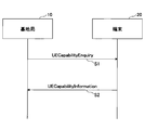
- FIG. 3 is a sequence diagram for explaining an example of terminal capability reporting according to the embodiment of the present invention.
- the base station 10 transmits a "UE Capacity Energy", that is, an inquiry of UE capability to the terminal 20.
- the terminal 20 transmits a "UE Capacity Information", that is, a report of the UE capability to the base station 10.
- the "UE Capacity Information” includes the UE capability supported by the terminal 20.
- Base station 10 identifies the supported UE capabilities based on the received "UECapacity Information”.
- UECapacity Information includes an information element “RF-Parameters” used for notification of capabilities related to wireless communication.
- RF-Parameters includes an information element "modified MPR-Behavior” indicating the ability related to MPR (Maximum Power Reduction).
- Modified MPR-Behavior is a bitmap showing which specification is supported when MPR is introduced or changed in the future. For example, the leftmost bit of "modified MPR-Behavior" set for a certain frequency band corresponds to the first specification in the frequency band, and the next bit corresponds to the second specification in the frequency band.
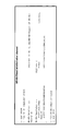
- FIG. 4 is a diagram showing an example (1) of a parameter related to spectrum radiation in the embodiment of the present invention.
- the information element "Additional SpectramEmission" shown in FIG. 4 notifies the terminal 20 from the base station 10 of the limitation relating to the spectrum radiation of UL transmission.
- the “Additional Spectrum Emission” shown in FIG. 4 is included in the "NR-NS-PmaxList”. Further, “NR-NS-PmaxList” is included in “MultiFreequencyBandListNR-SIB”. Further, “MultiFreequencyBandListNR-SIB” is included in “FreequencyInfoUL-SIB”. Further, “FreequencyInfoUL-SIB” is included in “UplinkConfigCommonSIB”. Further, “UplinkConfigCommonSIB” is included in "ServingCellConfigCommonSIB”. Further, “ServingCellConfigCommonSIB” is included in “SIB1". “SIB1” is one of the broadcast information transmitted from the base station 10 to the terminal 20. The “Additional Spectrum Emission” may be transmitted from the base station 10 to the terminal 20 by the broadcast information "SIB2" or “SIB4". The “Additional Spectram Emission” may be notified for each frequency or for each frequency band.
- FIG. 5 is a diagram showing an example (2) of a parameter related to spectrum radiation in the embodiment of the present invention.
- the information element "AdditionalSpectrumEmission" can be set to an integer value from 0 to 7.
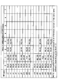
- FIG. 6 is a diagram showing an example (3) of a parameter related to spectrum radiation in the embodiment of the present invention.
- FR1 Frequency Range 1
- the terminal 20 acquires the required specifications related to spectrum radiation by the "Network signaling label" notified from the network.
- the Network signaling label is "NS_04”
- the required specifications of the line “NS_04” shown in FIG. 6 are applied, the NR band is "n41”, and the frequency band is "10, 15, 20, 40".
- 50, 60, 80, 90, 100 A-MPR (additional MPR) and the like are set.
- the “Network signaling label” is also referred to as an “NS value”.
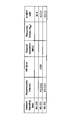
- FIG. 7 is a diagram showing an example (4) of a parameter related to spectrum radiation in the embodiment of the present invention.
- the “Network signaling label” described with reference to FIG. 6 is specified by the mapping of the value notified by the information element “Additional Spectrum Emission” with the NR band shown in FIG. 7 and the value of the “Additional Spectrum Emission”. For example, in the case of the band "n1”, "NS_01” is mapped to the value 0, "NS_100” is mapped to the value 1, “NS_05” is mapped to the value 2, and “NS_05U” is mapped to the value 3.
- FIG. 8 is a diagram showing an example (5) of a parameter related to spectrum radiation in the embodiment of the present invention.
- the terminal 20 acquires the required specifications related to spectrum radiation by the "Network signaling label" notified from the network.
- the required specifications of the line "NS_201” shown in FIG. 8 are applied, and the NR band is set to "n258", A-MPR, or the like.
- FIG. 9 is a diagram showing an example (6) of a parameter related to spectrum radiation in the embodiment of the present invention.
- the “Network signaling label” described with reference to FIG. 8 is specified by the mapping of the value notified by the information element “Additional Spectrum Emission” with the NR band shown in FIG. 9 and the value of the “Additional Spectrum Emission”. For example, in the case of the band "n258”, "NS_200” is mapped to the value 0, and "NS_201" is mapped to the value 1.
- FIG. 10 is a diagram showing an example (1) of parameters related to terminal capability reporting in the embodiment of the present invention.
- the "modified MPR-Behavior" associated with the frequency band represented by “FreqBandIndicatorNR” is composed of, for example, an 8-bit bitmap.
- “Modified MPR-Behavior” defines MPR or A-MPR in a certain frequency band.
- the "RF-Parameters” is an information element for notifying the base station 10 of the terminal capability, and is included in the "UE-NR-Capability".
- the "UE-NR-Capacity” is further included in the "UE Capability Information” and is reported from the terminal 20 to the base station 10 as shown in FIG.
- FIG. 11 is a diagram showing an example (2) of parameters related to terminal capability reporting in the embodiment of the present invention.
- FIG. 11 shows an example in which the specifications of MPR in a certain frequency band are notified by a bitmap by "modified MPR-Behavior".
- the leftmost bit in the bitmap indicates whether or not it supports the provisions relating to continuous intraband MPR in EN-DC. .. Further, when the frequency band is "n41", the bit next to the leftmost bit in the bitmap indicates whether or not the provision relating to MPR of the discontinuous intraband in EN-DC is supported. As shown in FIG. 11, when the frequency band is "n71", the leftmost bit in the bitmap indicates whether or not it supports the provisions relating to continuous intraband MPR in EN-DC.
- the bit values included in the above bitmap may be defined as supported by "1" and not supported by "0".
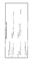
- FIG. 12 is a diagram showing an example of changing the specifications related to the terminal capability report in the embodiment of the present invention.
- the "modified MPR-Behavior" included in the "RF-Parameters" is when the MPR or A-MPR supported by the terminal 20 is introduced or changed in a future release version. Used for notification of.
- the “modified MPR-Behavior” is an information element that notifies an 8-bit bitmap for each frequency band.
- the base station 10 will support all the NS values described in FIGS. 7 and 9 in the corresponding frequency band. It may be specified, the base station 10 may consider that the terminal 20 supports all NS values, or the base station 10 may assume that the terminal 20 supports all NS values.
- the above “all NS values” may be NS values corresponding to a specific release version.
- the base station 10 when the base station 10 receives a UE capability report in which the frequency band is "n8" and “modified MPR-Behavior" is not set in "RF-Parameters", the base station 10 transmits the UE capability report.
- the terminal 20 may be specified to support all of "NR_01”, “NR_100”, “NR_43” and “NR_43U”.
- the base station 10 when the base station 10 receives a UE capability report in which the frequency band is "n258" and "modified MPR-Behavior" is not set in "RF-Parameters", the base station 10 receives the UE capability report.
- the transmitting terminal 20 may be specified to support all of "NR_200” and "NR_201".
- the network causes the terminal 20 to emit spectrum radiation in the frequency band. It can be specified that all such one or more required specifications are supported. Thereby, it is possible to specify that the terminal 20 satisfies the required specifications related to spectrum radiation in the frequency band in which the specifications related to MPR have not been changed.
- the network can specify the terminal capability in the wireless communication system.
- the base station 10 and the terminal 20 include a function of carrying out the above-described embodiment.
- the base station 10 and the terminal 20 may each have only a part of the functions in the embodiment.
- FIG. 13 is a diagram showing an example of the functional configuration of the base station 10 according to the embodiment of the present invention.
- the base station 10 includes a transmission unit 110, a reception unit 120, a setting unit 130, and a control unit 140.
- the functional configuration shown in FIG. 13 is only an example. Any function classification and name of the functional unit may be used as long as the operation according to the embodiment of the present invention can be executed.
- the transmission unit 110 includes a function of generating a signal to be transmitted to the terminal 20 side and transmitting the signal wirelessly. Further, the transmission unit 110 transmits a message between network nodes to another network node.
- the receiving unit 120 includes a function of receiving various signals transmitted from the terminal 20 and acquiring information of, for example, a higher layer from the received signals. Further, the transmission unit 110 has a function of transmitting NR-PSS, NR-SSS, NR-PBCH, DL / UL control signals and the like to the terminal 20. In addition, the receiving unit 120 receives a message between network nodes from another network node.
- the setting unit 130 stores preset setting information and various setting information to be transmitted to the terminal 20.
- the content of the setting information is, for example, information related to transmission / reception settings according to the UE capability of the terminal 20.
- control unit 140 controls the processing of the UE capability report regarding the radio parameter received from the terminal 20. Further, the control unit 140 notifies the terminal 20 of the information related to the spectrum radiation.
- the function unit related to signal transmission in the control unit 140 may be included in the transmission unit 110, and the function unit related to signal reception in the control unit 140 may be included in the reception unit 120.
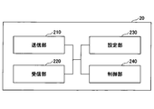
- FIG. 14 is a diagram showing an example of the functional configuration of the terminal 20 according to the embodiment of the present invention.
- the terminal 20 has a transmission unit 210, a reception unit 220, a setting unit 230, and a control unit 240.
- the functional configuration shown in FIG. 14 is only an example. Any function classification and name of the functional unit may be used as long as the operation according to the embodiment of the present invention can be executed.
- the transmission unit 210 creates a transmission signal from the transmission data and wirelessly transmits the transmission signal.
- the receiving unit 220 wirelessly receives various signals and acquires a signal of a higher layer from the received signal of the physical layer. Further, the receiving unit 220 has a function of receiving NR-PSS, NR-SSS, NR-PBCH, DL / UL / SL control signals and the like transmitted from the base station 10. Further, for example, the transmission unit 210 connects the other terminal 20 to PSCCH (Physical Sidelink Control Channel), PSCH (Physical Sidelink Shared Channel), PSDCH (Physical Sidelink Discovery Channel), PSBCH (Physical Sidelink Broadcast Channel) as D2D communication. Etc., and the receiving unit 120 receives PSCCH, PSCH, PSDCH, PSBCH, etc. from the other terminal 20.
- PSCCH Physical Sidelink Control Channel
- PSCH Physical Sidelink Shared Channel
- PSDCH Physical Sidelink Discovery Channel
- PSBCH Physical Sidelink Broadcast Channel
- the setting unit 230 stores various setting information received from the base station 10 by the receiving unit 220.
- the setting unit 230 also stores preset setting information.
- the content of the setting information is, for example, information related to transmission / reception setting according to the UE capability.
- control unit 240 controls the UE capability report regarding the radio parameters of the terminal 20.
- control unit 140 controls the spectrum radiation.
- the function unit related to signal transmission in the control unit 240 may be included in the transmission unit 210, and the function unit related to signal reception in the control unit 240 may be included in the reception unit 220.
- each functional block may be realized by using one device that is physically or logically connected, or directly or indirectly (for example, by two or more devices that are physically or logically separated). , Wired, wireless, etc.) and may be realized using these plurality of devices.
- the functional block may be realized by combining the software with the one device or the plurality of devices.
- Functions include judgment, decision, judgment, calculation, calculation, processing, derivation, investigation, search, confirmation, reception, transmission, output, access, solution, selection, selection, establishment, comparison, assumption, expectation, and assumption.
- broadcasting notifying, communicating, forwarding, configuring, reconfiguring, allocating, mapping, assigning, etc., but only these.
- a functional block that makes transmission function is called a transmitting unit (transmitting unit) or a transmitter (transmitter).
- transmitting unit transmitting unit
- transmitter transmitter
- the base station 10, the terminal 20, and the like in one embodiment of the present disclosure may function as a computer that processes the wireless communication method of the present disclosure.
- FIG. 15 is a diagram showing an example of the hardware configuration of the base station 10 and the terminal 20 according to the embodiment of the present disclosure.
- the above-mentioned base station 10 and terminal 20 are physically configured as a computer device including a processor 1001, a storage device 1002, an auxiliary storage device 1003, a communication device 1004, an input device 1005, an output device 1006, a bus 1007, and the like. May be good.
- the word “device” can be read as a circuit, device, unit, etc.
- the hardware configuration of the base station 10 and the terminal 20 may be configured to include one or more of the devices shown in the figure, or may be configured not to include some of the devices.
- the processor 1001 For each function of the base station 10 and the terminal 20, the processor 1001 performs an operation by loading predetermined software (program) on the hardware such as the processor 1001 and the storage device 1002, and controls the communication by the communication device 1004. It is realized by controlling at least one of reading and writing of data in the storage device 1002 and the auxiliary storage device 1003.
- Processor 1001 operates, for example, an operating system to control the entire computer.
- the processor 1001 may be composed of a central processing unit (CPU: Central Processing Unit) including an interface with a peripheral device, a control device, an arithmetic unit, a register, and the like.
- CPU Central Processing Unit
- control unit 140, control unit 240, and the like may be realized by the processor 1001.
- the processor 1001 reads a program (program code), a software module, data, or the like from at least one of the auxiliary storage device 1003 and the communication device 1004 into the storage device 1002, and executes various processes according to these.
- a program program that causes a computer to execute at least a part of the operations described in the above-described embodiment is used.
- the control unit 140 of the base station 10 shown in FIG. 13 may be realized by a control program stored in the storage device 1002 and operated by the processor 1001.
- the control unit 240 of the terminal 20 shown in FIG. 14 may be realized by a control program stored in the storage device 1002 and operated by the processor 1001.
- Processor 1001 may be implemented by one or more chips.
- the program may be transmitted from the network via a telecommunication line.
- the storage device 1002 is a computer-readable recording medium, for example, by at least one of ROM (Read Only Memory), EPROM (Erasable Programmable ROM), EPROM (Electrically Erasable Programmable ROM), RAM (Random Access Memory) and the like. It may be configured.
- the storage device 1002 may be referred to as a register, a cache, a main memory (main storage device), or the like.
- the storage device 1002 can store a program (program code), a software module, or the like that can be executed to implement the communication method according to the embodiment of the present disclosure.
- the auxiliary storage device 1003 is a computer-readable recording medium, and is, for example, an optical disk such as a CD-ROM (Compact Disc ROM), a hard disk drive, a flexible disk, an optical magnetic disk (for example, a compact disk, a digital versatile disk, Blu).
- -It may be composed of at least one of a ray® disc), a smart card, a flash memory (eg, a card, a stick, a key drive), a floppy® disc, a magnetic strip, and the like.
- the storage medium described above may be, for example, a database, server or other suitable medium containing at least one of the storage device 1002 and the auxiliary storage device 1003.
- the communication device 1004 is hardware (transmission / reception device) for communicating between computers via at least one of a wired network and a wireless network, and is also referred to as, for example, a network device, a network controller, a network card, a communication module, or the like.
- the communication device 1004 includes, for example, a high frequency switch, a duplexer, a filter, a frequency synthesizer, and the like in order to realize at least one of frequency division duplex (FDD: Frequency Division Duplex) and time division duplex (TDD: Time Division Duplex). It may be composed of.
- FDD Frequency Division Duplex
- TDD Time Division Duplex
- the transmission / reception unit may be physically or logically separated from each other in the transmission unit and the reception unit.
- the input device 1005 is an input device (for example, a keyboard, a mouse, a microphone, a switch, a button, a sensor, etc.) that receives an input from the outside.
- the output device 1006 is an output device (for example, a display, a speaker, an LED lamp, etc.) that outputs to the outside.
- the input device 1005 and the output device 1006 may have an integrated configuration (for example, a touch panel).
- each device such as the processor 1001 and the storage device 1002 is connected by a bus 1007 for communicating information.
- the bus 1007 may be configured by using a single bus, or may be configured by using a different bus for each device.
- the base station 10 and the terminal 20 are hardware such as a microprocessor, a digital signal processor (DSP: Digital Signal Processor), an ASIC (Application Specific Integrated Circuit), a PLD (Programmable Logic Device), and an FPGA (Field Programmable Gate Array). It may be configured to include, and a part or all of each functional block may be realized by the hardware. For example, processor 1001 may be implemented using at least one of these hardware.
- DSP Digital Signal Processor
- ASIC Application Specific Integrated Circuit
- PLD Programmable Logic Device
- FPGA Field Programmable Gate Array
- the base station provides information for notifying one or more values indicating the required specifications related to spectrum radiation in a certain frequency band and information for requesting the reporting of terminal capability. If the report does not include information indicating the receiving unit received from the receiver and whether or not the operation related to the modified MPR (Maximum Power Reduction) in the frequency band is supported, a value indicating the required specifications related to the spectrum radiation.
- a terminal having a control unit that supports all of them and a transmission unit that transmits the report to the base station is provided.
- the network is related to the spectrum radiation of the terminal 20 in the frequency band. It can be specified that it supports all one or more required specifications. Thereby, it is possible to specify that the terminal 20 satisfies the required specifications related to spectrum radiation in the frequency band in which the specifications related to MPR have not been changed. That is, the network can specify the terminal capability in the wireless communication system.
- a transmitter that transmits information for notifying one or more values indicating the required specifications related to spectrum radiation in a certain frequency band and information for requesting reporting of the terminal capability to the terminal. If the receiver that receives the report from the terminal and the report do not include information indicating whether or not the operation related to the modified MPR (Maximum Power Reduction) in the frequency band is supported, the spectrum.
- a base station is provided having a control unit that determines that the terminal supports all the values indicating the required specifications related to radiation.
- the network is related to the spectrum radiation of the terminal 20 in the frequency band. It can be specified that it supports all one or more required specifications. Thereby, it is possible to specify that the terminal 20 satisfies the required specifications related to spectrum radiation in the frequency band in which the specifications related to MPR have not been changed. That is, the network can specify the terminal capability in the wireless communication system.
- a receiving procedure for receiving information for notifying one or more values indicating the required specifications related to spectrum radiation in a certain frequency band and information for requesting reporting of terminal capability from the base station. And, if the report does not include information indicating whether or not to support the operation related to the changed MPR (Maximum Power Reduction) in the frequency band, the control that supports all the values indicating the required specifications related to the spectrum radiation.
- a communication method is provided in which the terminal executes the procedure and the transmission procedure for transmitting the report to the base station.
- the network is related to the spectrum radiation of the terminal 20 in the frequency band. It can be specified that it supports all one or more required specifications. Thereby, it is possible to specify that the terminal 20 satisfies the required specifications related to spectrum radiation in the frequency band in which the specifications related to MPR have not been changed. That is, the network can specify the terminal capability in the wireless communication system.
- the boundary of the functional unit or the processing unit in the functional block diagram does not always correspond to the boundary of the physical component.
- the operation of the plurality of functional units may be physically performed by one component, or the operation of one functional unit may be physically performed by a plurality of components.
- the processing order may be changed as long as there is no contradiction.
- the base station 10 and the terminal 20 have been described with reference to functional block diagrams, but such devices may be implemented in hardware, software, or a combination thereof.
- the software operated by the processor of the base station 10 according to the embodiment of the present invention and the software operated by the processor of the terminal 20 according to the embodiment of the present invention are random access memory (RAM), flash memory, and read-only memory, respectively. It may be stored in (ROM), EPROM, EEPROM, registers, hard disk (HDD), removable disk, CD-ROM, database, server or any other suitable storage medium.
- information notification includes physical layer signaling (for example, DCI (Downlink Control Information), UCI (Uplink Control Information)), higher layer signaling (for example, RRC (Radio Resource Control) signaling, MAC (Medium Access Control) signaling, etc. Broadcast information (MIB (Master Information Block), SIB (System Information Block)), other signals, or a combination thereof may be used.
- RRC signaling may be referred to as an RRC message, for example, RRC. It may be a connection setup (RRCConnectionSetup) message, an RRC connection reconfiguration (RRCConnectionReconfiguration) message, or the like.
- Each aspect / embodiment described in the present disclosure includes LTE (Long Term Evolution), LTE-A (LTE-Advanced), SUPER 3G, IMT-Advanced, 4G (4th generation mobile communication system), and 5G (5th generation mobile communication).
- system FRA (Future Radio Access), NR (new Radio), W-CDMA (registered trademark), GSM (registered trademark), CDMA2000, UMB (Ultra Mobile Broadband), IEEE 802.11 (Wi-Fi (registered trademark)) )), LTE 802.16 (WiMAX®), IEEE 802.20, UWB (Ultra-WideBand), Bluetooth®, and other systems that utilize suitable systems and have been extended based on these. It may be applied to at least one of the next generation systems. Further, a plurality of systems may be applied in combination (for example, a combination of at least one of LTE and LTE-A and 5G).
- the specific operation performed by the base station 10 in the present specification may be performed by its upper node.
- various operations performed for communication with the terminal 20 are performed by the base station 10 and other network nodes other than the base station 10 (for example, it is clear that it can be done by at least one of (but not limited to, MME, S-GW, etc.).
- the other network node may be a combination of a plurality of other network nodes (for example, MME and S-GW). ..
- the information, signals, etc. described in the present disclosure can be output from the upper layer (or lower layer) to the lower layer (or upper layer). Input / output may be performed via a plurality of network nodes.
- the input / output information and the like may be stored in a specific location (for example, memory) or may be managed using a management table. Input / output information and the like can be overwritten, updated, or added. The output information and the like may be deleted. The input information or the like may be transmitted to another device.
- the determination in the present disclosure may be made by a value represented by 1 bit (0 or 1), by a boolean value (Boolean: true or false), or by comparing numerical values (for example,). , Comparison with a predetermined value).
- Software whether referred to as software, firmware, middleware, microcode, hardware description language, or by any other name, is an instruction, instruction set, code, code segment, program code, program, subprogram, software module.
- Applications, software applications, software packages, routines, subroutines, objects, executable files, execution threads, procedures, features, etc. should be broadly interpreted.
- software, instructions, information, etc. may be transmitted and received via a transmission medium.
- a transmission medium For example, a website that uses at least one of wired technology (coaxial cable, fiber optic cable, twisted pair, digital subscriber line (DSL: Digital Subscriber Line), etc.) and wireless technology (infrared, microwave, etc.).
- wired technology coaxial cable, fiber optic cable, twisted pair, digital subscriber line (DSL: Digital Subscriber Line), etc.
- wireless technology infrared, microwave, etc.
- the information, signals, etc. described in this disclosure may be represented using any of a variety of different techniques.
- data, instructions, commands, information, signals, bits, symbols, chips, etc. that may be referred to throughout the above description are voltages, currents, electromagnetic waves, magnetic fields or magnetic particles, light fields or photons, or any of these. It may be represented by a combination of.
- a channel and a symbol may be a signal (signaling).
- the signal may be a message.
- the component carrier CC: Component Carrier
- CC Component Carrier
- system and “network” used in this disclosure are used interchangeably.
- the information, parameters, etc. described in the present disclosure may be expressed using absolute values, relative values from predetermined values, or using other corresponding information. It may be represented.
- the radio resource may be one indicated by an index.
- base station Base Station
- radio base station base station
- base station device fixed station
- NodeB NodeB
- eNodeB eNodeB
- GNB gNodeB
- access point “ transmission point ”,“ reception point ”,“ transmission / reception point ”,“ cell ”,“ sector ”
- Terms such as “cell group,” “carrier,” and “component carrier” can be used interchangeably.
- Base stations are sometimes referred to by terms such as macrocells, small cells, femtocells, and picocells.
- the base station can accommodate one or more (for example, three) cells.
- a base station accommodates multiple cells, the entire coverage area of the base station can be divided into multiple smaller areas, each smaller area being a base station subsystem (eg, a small indoor base station (RRH:)).
- Communication services can also be provided by Remote Radio Head).
- the term "cell” or “sector” refers to part or all of the coverage area of at least one of the base stations and base station subsystems that provide communication services in this coverage. Point to.
- MS Mobile Station
- UE User Equipment
- Mobile stations can be subscriber stations, mobile units, subscriber units, wireless units, remote units, mobile devices, wireless devices, wireless communication devices, remote devices, mobile subscriber stations, access terminals, mobile terminals, wireless, depending on the trader. It may also be referred to as a terminal, remote terminal, handset, user agent, mobile client, client, or some other suitable term.
- At least one of the base station and the mobile station may be called a transmitting device, a receiving device, a communication device, or the like. At least one of the base station and the mobile station may be a device mounted on the mobile body, the mobile body itself, or the like.
- the moving body may be a vehicle (for example, a car, an airplane, etc.), an unmanned moving body (for example, a drone, an autonomous vehicle, etc.), or a robot (manned or unmanned type). ) May be.
- at least one of the base station and the mobile station includes a device that does not necessarily move during communication operation.
- at least one of the base station and the mobile station may be an IoT (Internet of Things) device such as a sensor.
- IoT Internet of Things
- the base station in the present disclosure may be read by the user terminal.
- the communication between the base station and the user terminal is replaced with the communication between a plurality of terminals 20 (for example, it may be called D2D (Device-to-Device), V2X (Vehicle-to-Everything), etc.).
- D2D Device-to-Device
- V2X Vehicle-to-Everything
- Each aspect / embodiment of the present disclosure may be applied to the configuration.
- the terminal 20 may have the function of the base station 10 described above.
- words such as "up” and “down” may be read as words corresponding to communication between terminals (for example, "side”).
- an uplink channel, a downlink channel, and the like may be read as a side channel.
- the user terminal in the present disclosure may be read as a base station.
- the base station may have the functions of the user terminal described above.
- determining and “determining” used in this disclosure may include a wide variety of actions.
- “Judgment” and “decision” are, for example, judgment (judging), calculation (calculating), calculation (computing), processing (processing), derivation (deriving), investigation (investigating), search (looking up, search, inquiry). (For example, searching in a table, database or another data structure), ascertaining may be regarded as “judgment” or “decision”.
- judgment and “decision” are receiving (for example, receiving information), transmitting (for example, transmitting information), input (input), output (output), and access.
- Accessing (for example, accessing data in memory) may be regarded as "judgment” or “decision”.
- judgment and “decision” mean that the things such as solving, selecting, choosing, establishing, and comparing are regarded as “judgment” and “decision”. Can include. That is, “judgment” and “decision” may include considering some action as “judgment” and “decision”. Further, “judgment (decision)” may be read as “assuming”, “expecting”, “considering” and the like.
- connection means any direct or indirect connection or connection between two or more elements, and each other. It can include the presence of one or more intermediate elements between two “connected” or “combined” elements.
- the connection or connection between the elements may be physical, logical, or a combination thereof.
- connection may be read as "access”.
- the two elements use at least one of one or more wires, cables and printed electrical connections, and, as some non-limiting and non-comprehensive examples, the radio frequency domain. Can be considered to be “connected” or “coupled” to each other using electromagnetic energies having wavelengths in the microwave and light (both visible and invisible) regions.
- the reference signal can also be abbreviated as RS (Reference Signal), and may be called a pilot (Pilot) depending on the applicable standard.
- RS Reference Signal
- Pilot Pilot
- references to elements using designations such as “first” and “second” as used in this disclosure does not generally limit the quantity or order of those elements. These designations can be used in the present disclosure as a convenient way to distinguish between two or more elements. Thus, references to the first and second elements do not mean that only two elements can be adopted, or that the first element must somehow precede the second element.
- the wireless frame may be composed of one or more frames in the time domain. Each one or more frames in the time domain may be referred to as a subframe. Subframes may further consist of one or more slots in the time domain.
- the subframe may have a fixed time length (eg, 1 ms) that does not depend on numerology.
- the numerology may be a communication parameter that applies to at least one of the transmission and reception of a signal or channel.
- Numerology includes, for example, subcarrier spacing (SCS: SubCarrier Spacing), bandwidth, symbol length, cyclic prefix length, transmission time interval (TTI: Transmission Time Interval), number of symbols per TTI, wireless frame configuration, and transceiver.
- SCS SubCarrier Spacing
- TTI Transmission Time Interval
- TTI Transmission Time Interval
- transceiver At least one of a specific filtering process performed in the frequency domain, a specific windowing process performed by the transceiver in the time domain, and the like may be indicated.
- the slot may be composed of one or more symbols in the time domain (OFDM (Orthogonal Frequency Division Multiplexing) symbol, SC-FDMA (Single Carrier Frequency Division Multiple Access) symbol, etc.). Slots may be in time units based on numerology.
- OFDM Orthogonal Frequency Division Multiplexing
- SC-FDMA Single Carrier Frequency Division Multiple Access
- the slot may include a plurality of mini slots. Each minislot may consist of one or more symbols in the time domain. Further, the mini slot may be referred to as a sub slot. A minislot may consist of a smaller number of symbols than the slot.
- PDSCH (or PUSCH) transmitted in time units larger than the minislot may be referred to as PDSCH (or PUSCH) mapping type A.
- the PDSCH (or PUSCH) transmitted using the minislot may be referred to as the PDSCH (or PUSCH) mapping type B.
- the wireless frame, subframe, slot, minislot and symbol all represent the time unit when transmitting a signal.
- the radio frame, subframe, slot, minislot and symbol may have different names corresponding to each.
- one subframe may be called a transmission time interval (TTI), a plurality of consecutive subframes may be called TTI, and one slot or one minislot may be called TTI.
- TTI transmission time interval
- the unit representing TTI may be called a slot, a mini slot, or the like instead of a subframe.
- TTI refers to, for example, the minimum time unit of scheduling in wireless communication.
- the base station schedules each terminal 20 to allocate radio resources (frequency bandwidth that can be used in each terminal 20, transmission power, etc.) in TTI units.
- the definition of TTI is not limited to this.
- the TTI may be a transmission time unit such as a channel-encoded data packet (transport block), a code block, or a code word, or may be a processing unit such as scheduling or link adaptation.
- the time interval for example, the number of symbols
- the transport block, code block, code word, etc. may be shorter than the TTI.
- one or more TTIs may be the minimum time unit for scheduling. Further, the number of slots (number of mini-slots) constituting the minimum time unit of the scheduling may be controlled.
- a TTI having a time length of 1 ms may be referred to as a normal TTI (TTI in LTE Rel. 8-12), a normal TTI, a long TTI, a normal subframe, a normal subframe, a long subframe, a slot, or the like.
- TTIs shorter than normal TTIs may be referred to as shortened TTIs, short TTIs, partial TTIs (partial or fractional TTIs), shortened subframes, short subframes, minislots, subslots, slots, and the like.
- the long TTI (for example, normal TTI, subframe, etc.) may be read as a TTI having a time length of more than 1 ms, and the short TTI (for example, shortened TTI, etc.) is less than the TTI length of the long TTI and 1 ms. It may be read as a TTI having the above TTI length.
- the resource block (RB) is a resource allocation unit in the time domain and the frequency domain, and may include one or a plurality of continuous subcarriers in the frequency domain.
- the number of subcarriers contained in the RB may be the same regardless of the numerology, and may be, for example, 12.
- the number of subcarriers contained in the RB may be determined based on numerology.
- the time domain of the RB may include one or more symbols, and may have a length of 1 slot, 1 mini slot, 1 subframe, or 1 TTI.
- Each 1TTI, 1 subframe, etc. may be composed of one or a plurality of resource blocks.
- One or more RBs include a physical resource block (PRB: Physical RB), a sub-carrier group (SCG: Sub-Carrier Group), a resource element group (REG: Resource Element Group), a PRB pair, an RB pair, and the like. May be called.
- PRB Physical resource block
- SCG Sub-Carrier Group
- REG Resource Element Group
- PRB pair an RB pair, and the like. May be called.
- the resource block may be composed of one or a plurality of resource elements (RE: Resource Element).
- RE Resource Element
- 1RE may be a radio resource area of 1 subcarrier and 1 symbol.
- Bandwidth part (which may also be called partial bandwidth) may represent a subset of consecutive common resource blocks (RBs) for a certain neurology in a carrier.
- the common RB may be specified by the index of the RB with respect to the common reference point of the carrier.
- PRBs may be defined in a BWP and numbered within that BWP.
- the BWP may include a BWP for UL (UL BWP) and a BWP for DL (DL BWP).
- UL BWP UL BWP
- DL BWP DL BWP
- One or more BWPs may be set in one carrier for the UE.
- At least one of the configured BWPs may be active, and the UE may not expect to send or receive a given signal / channel outside the active BWP.
- “cell”, “carrier” and the like in this disclosure may be read as “BWP”.
- the above-mentioned structures such as wireless frames, subframes, slots, minislots and symbols are merely examples.
- the number of subframes contained in a wireless frame the number of slots per subframe or wireless frame, the number of minislots contained in a slot, the number of symbols and RBs contained in a slot or minislot, and the number of RBs.
- the number of subcarriers, the number of symbols in the TTI, the symbol length, the cyclic prefix (CP: Cyclic Prefix) length, and other configurations can be changed in various ways.
- the term "A and B are different” may mean “A and B are different from each other”.
- the term may mean that "A and B are different from C”.
- Terms such as “separate” and “combined” may be interpreted in the same way as “different”.
- the notification of predetermined information (for example, the notification of "being X") is not limited to the explicit one, but is performed implicitly (for example, the notification of the predetermined information is not performed). May be good.
- UECapacityEnquiry is an example of information requesting a report of terminal capability.
- UECapacity Information is an example of reporting terminal capabilities.
- the NS value is an example of a value indicating the required specifications related to spectrum radiation.
- the Additional Spectrum Emission is an example of information for notifying a value indicating a required specification related to spectrum radiation.
- the modified MPR-Behavior is an example of information indicating whether or not to support the operation related to the modified MPR.
- Base station 110 Transmission unit 120 Reception unit 130 Setting unit 140 Control unit 20 Terminal 210 Transmission unit 220 Reception unit 230 Setting unit 240 Control unit 1001 Processor 1002 Storage device 1003 Auxiliary storage device 1004 Communication device 1005 Input device 1006 Output device
Landscapes
- Engineering & Computer Science (AREA)
- Computer Networks & Wireless Communication (AREA)
- Signal Processing (AREA)
- Databases & Information Systems (AREA)
- Mobile Radio Communication Systems (AREA)
Abstract
Un terminal comprenant une unité de réception reçoit, en provenance d'une station de base, des informations qui donnent une notification d'une ou plusieurs valeurs qui indiquent des spécifications de demande relatives à des émissions spectrales pour une bande de fréquences donnée et des informations qui demandent un rapport sur la capacité d'un terminal, une unité de commande qui, lorsque des informations qui indiquent si une opération relative à une réduction de puissance maximale (MPR) qui a été modifiée pour la bande de fréquences donnée est prise en charge ne doivent pas être incluses dans le rapport, prend en charge toutes les valeurs qui indiquent les spécifications de demande relatives aux émissions spectrales, et une unité de transmission qui transmet le rapport à la station de base.
Priority Applications (5)
| Application Number | Priority Date | Filing Date | Title |
|---|---|---|---|
| CN202080093780.2A CN114982262A (zh) | 2020-01-24 | 2020-01-24 | 终端、基站以及通信方法 |
| EP20916223.9A EP4096262A4 (fr) | 2020-01-24 | 2020-01-24 | Terminal, station de base, et procédé de communication |
| JP2021572237A JP7369211B2 (ja) | 2020-01-24 | 2020-01-24 | 端末、基地局及び通信方法 |
| US17/793,256 US20230345231A1 (en) | 2020-01-24 | 2020-01-24 | Terminal, base station, and communication method |
| PCT/JP2020/002549 WO2021149246A1 (fr) | 2020-01-24 | 2020-01-24 | Terminal, station de base, et procédé de communication |
Applications Claiming Priority (1)
| Application Number | Priority Date | Filing Date | Title |
|---|---|---|---|
| PCT/JP2020/002549 WO2021149246A1 (fr) | 2020-01-24 | 2020-01-24 | Terminal, station de base, et procédé de communication |
Publications (1)
| Publication Number | Publication Date |
|---|---|
| WO2021149246A1 true WO2021149246A1 (fr) | 2021-07-29 |
Family
ID=76991832
Family Applications (1)
| Application Number | Title | Priority Date | Filing Date |
|---|---|---|---|
| PCT/JP2020/002549 WO2021149246A1 (fr) | 2020-01-24 | 2020-01-24 | Terminal, station de base, et procédé de communication |
Country Status (5)
| Country | Link |
|---|---|
| US (1) | US20230345231A1 (fr) |
| EP (1) | EP4096262A4 (fr) |
| JP (1) | JP7369211B2 (fr) |
| CN (1) | CN114982262A (fr) |
| WO (1) | WO2021149246A1 (fr) |
Cited By (1)
| Publication number | Priority date | Publication date | Assignee | Title |
|---|---|---|---|---|
| WO2023201752A1 (fr) * | 2022-04-22 | 2023-10-26 | 北京小米移动软件有限公司 | Procédé de traitement d'information et appareil associé |
Families Citing this family (1)
| Publication number | Priority date | Publication date | Assignee | Title |
|---|---|---|---|---|
| US20220232371A1 (en) * | 2019-06-06 | 2022-07-21 | Ntt Docomo, Inc. | Terminal and base station |
Citations (2)
| Publication number | Priority date | Publication date | Assignee | Title |
|---|---|---|---|---|
| JP2013098592A (ja) * | 2011-10-27 | 2013-05-20 | Ntt Docomo Inc | 移動通信方法及び無線基地局 |
| JP2017513392A (ja) * | 2014-03-28 | 2017-05-25 | エルジー エレクトロニクス インコーポレイティド | 無線通信システムにおける端末により実行されるd2d動作方法及びその方法を利用する端末 |
Family Cites Families (2)
| Publication number | Priority date | Publication date | Assignee | Title |
|---|---|---|---|---|
| US8867436B2 (en) * | 2009-07-31 | 2014-10-21 | Qualcomm Incorporated | Support for optional system parameter values |
| JP6337134B2 (ja) | 2014-10-07 | 2018-06-06 | 株式会社Nttドコモ | ユーザ装置、移動通信システム、及び最大送信電力決定方法 |
-
2020
- 2020-01-24 WO PCT/JP2020/002549 patent/WO2021149246A1/fr unknown
- 2020-01-24 JP JP2021572237A patent/JP7369211B2/ja active Active
- 2020-01-24 CN CN202080093780.2A patent/CN114982262A/zh active Pending
- 2020-01-24 EP EP20916223.9A patent/EP4096262A4/fr active Pending
- 2020-01-24 US US17/793,256 patent/US20230345231A1/en active Pending
Patent Citations (2)
| Publication number | Priority date | Publication date | Assignee | Title |
|---|---|---|---|---|
| JP2013098592A (ja) * | 2011-10-27 | 2013-05-20 | Ntt Docomo Inc | 移動通信方法及び無線基地局 |
| JP2017513392A (ja) * | 2014-03-28 | 2017-05-25 | エルジー エレクトロニクス インコーポレイティド | 無線通信システムにおける端末により実行されるd2d動作方法及びその方法を利用する端末 |
Non-Patent Citations (6)
| Title |
|---|
| 3GPP TS 38.101-1, December 2019 (2019-12-01) |
| 3GPP TS 38.101-2, December 2019 (2019-12-01) |
| 3GPP TS 38.101-3, December 2019 (2019-12-01) |
| 3GPP TS 38.300, December 2019 (2019-12-01) |
| 3GPP TS 38.311, December 2019 (2019-12-01) |
| NOKIA NETWORKS: "Multiple NS/P-max handling", 3GPP DRAFT; R2-153460 HANDLING OF NS VALUES, 3RD GENERATION PARTNERSHIP PROJECT (3GPP), MOBILE COMPETENCE CENTRE ; 650, ROUTE DES LUCIOLES ; F-06921 SOPHIA-ANTIPOLIS CEDEX ; FRANCE, vol. RAN WG2, no. Beijing, China; 20150824 - 20150828, 23 August 2015 (2015-08-23), Mobile Competence Centre ; 650, route des Lucioles ; F-06921 Sophia-Antipolis Cedex ; France, XP051004177 * |
Cited By (1)
| Publication number | Priority date | Publication date | Assignee | Title |
|---|---|---|---|---|
| WO2023201752A1 (fr) * | 2022-04-22 | 2023-10-26 | 北京小米移动软件有限公司 | Procédé de traitement d'information et appareil associé |
Also Published As
| Publication number | Publication date |
|---|---|
| US20230345231A1 (en) | 2023-10-26 |
| JP7369211B2 (ja) | 2023-10-25 |
| EP4096262A4 (fr) | 2023-10-18 |
| CN114982262A (zh) | 2022-08-30 |
| JPWO2021149246A1 (fr) | 2021-07-29 |
| EP4096262A1 (fr) | 2022-11-30 |
Similar Documents
| Publication | Publication Date | Title |
|---|---|---|
| WO2021157090A1 (fr) | Terminal et procédé de communication | |
| WO2020230201A1 (fr) | Dispositif utilisateur et dispositif de station de base | |
| WO2020170405A1 (fr) | Équipement utilisateur et appareil de station de base | |
| WO2021149246A1 (fr) | Terminal, station de base, et procédé de communication | |
| WO2020235318A1 (fr) | Équipement utilisateur et dispositif de station de base | |
| WO2021140674A1 (fr) | Terminal et procédé de communication | |
| JP7073529B2 (ja) | 端末、基地局及び通信方法 | |
| WO2021199415A1 (fr) | Terminal et procédé de communication | |
| WO2021140673A1 (fr) | Terminal et procédé de communication | |
| WO2021149110A1 (fr) | Terminal et procédé de communication | |
| WO2020246185A1 (fr) | Terminal et station de base | |
| WO2021140677A1 (fr) | Terminal et procédé de communication | |
| WO2020194638A1 (fr) | Dispositif utilisateur et dispositif de station de base | |
| WO2021070396A1 (fr) | Terminal et procédé de communication | |
| WO2020194746A1 (fr) | Dispositif utilisateur et dispositif de station de base | |
| WO2020161824A1 (fr) | Dispositif utilisateur et dispositif de station de base | |
| JPWO2020170445A1 (ja) | ユーザ装置及び基地局装置 | |
| WO2020230623A1 (fr) | Équipement utilisateur et dispositif de station de base | |
| WO2021161476A1 (fr) | Terminal et procédé de communication | |
| WO2021161455A1 (fr) | Terminal et procédé de transmission d'informations de capacité | |
| WO2021215029A1 (fr) | Terminal et procédé de communication | |
| WO2022079780A1 (fr) | Terminal, station de base et procédé de communication | |
| WO2022079781A1 (fr) | Terminal, station de base et procédé de communication | |
| WO2021140676A1 (fr) | Terminal et procédé de communication | |
| WO2021214894A1 (fr) | Terminal et procédé de communication |
Legal Events
| Date | Code | Title | Description |
|---|---|---|---|
| 121 | Ep: the epo has been informed by wipo that ep was designated in this application |
Ref document number: 20916223 Country of ref document: EP Kind code of ref document: A1 |
|
| ENP | Entry into the national phase |
Ref document number: 2021572237 Country of ref document: JP Kind code of ref document: A |
|
| NENP | Non-entry into the national phase |
Ref country code: DE |
|
| ENP | Entry into the national phase |
Ref document number: 2020916223 Country of ref document: EP Effective date: 20220824 |