WO2020161824A1 - Dispositif utilisateur et dispositif de station de base - Google Patents
Dispositif utilisateur et dispositif de station de base Download PDFInfo
- Publication number
- WO2020161824A1 WO2020161824A1 PCT/JP2019/004222 JP2019004222W WO2020161824A1 WO 2020161824 A1 WO2020161824 A1 WO 2020161824A1 JP 2019004222 W JP2019004222 W JP 2019004222W WO 2020161824 A1 WO2020161824 A1 WO 2020161824A1
- Authority
- WO
- WIPO (PCT)
- Prior art keywords
- bwp
- base station
- communication
- initial
- information
- Prior art date
Links
Images


Classifications
-
- H—ELECTRICITY
- H04—ELECTRIC COMMUNICATION TECHNIQUE
- H04W—WIRELESS COMMUNICATION NETWORKS
- H04W72/00—Local resource management
- H04W72/04—Wireless resource allocation
Definitions
- the present invention relates to a user device and a base station device in a wireless communication system.
- NR New Radio
- LTE Long Term Evolution
- NR uses a method in which a user device uses part of the carrier bandwidth as a BWP (Bandwidth part).
- the BWP is composed of consecutive PRBs (Physical Resource Blocks).
- up to four BWPs can be set in the user apparatus in DL (Downlink) or UL (Uplink), respectively.
- the user device uses one active BWP to perform communication (for example, Non-Patent Document 2).
- the operation to specify BWP may not be specified depending on the communication setting method of the initial BWP used for initial connection.
- the present invention has been made in view of the above points, and an object of the present invention is to set communication to which BWP is applied in a wireless communication system.
- a reception unit that receives information specifying a BWP (Bandwidth part) and communication settings applied to the BWP from a base station device, information specifying the BWP, and an initial BWP used for initial connection. Based on the corresponding communication settings applied to the BWP, a control unit that specifies the BWP to be used, and communication settings applied to the BWP corresponding to the specified BWP are applied to communicate with the base station device.
- a user device having a communication unit is provided.
- FIG. 1 is a diagram for explaining a wireless communication system according to an embodiment of the present invention. It is a figure for demonstrating BWP. It is a sequence diagram for explaining an example of communication setting in the embodiment of the present invention. It is a specification change example (1) according to the first operation example in the embodiment of the present invention. It is a specification change example (2) according to the first operation example in the embodiment of the present invention. It is a specification change example (1) according to the second operation example in the embodiment of the present invention. It is a specification change example (2) according to the second operation example in the embodiment of the present invention. It is a specification change example (1) according to the third operation example in the embodiment of the present invention. It is a specification change example (2) according to the third operation example in the embodiment of the present invention.
- LTE Long Term Evolution
- LTE-Advanced LTE-Advanced and subsequent schemes (eg, NR) unless otherwise specified.
- SS Synchronization signal
- PSS Primary SS
- SSS Secondary SS
- PBCH Physical broadcast channel
- PRACH Physical Random access channel
- the duplex system may be a TDD (Time Division Duplex) system, an FDD (Frequency Division Duplex) system, or other (for example, Flexible Duplex). May be used.
- “configuring” a wireless parameter or the like may mean that a predetermined value is set in advance (Pre-configure), or the base station device 10 Alternatively, the wireless parameter notified from the user device 20 may be set.
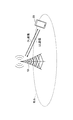
- FIG. 1 is a diagram for explaining a wireless communication system according to an embodiment of the present invention.
- the wireless communication system in the embodiment of the present invention includes a base station device 10 and a user device 20, as shown in FIG. Although one base station apparatus 10 and one user apparatus 20 are shown in FIG. 1, this is an example, and a plurality of each may be provided.
- the base station device 10 is a communication device that provides one or more cells and performs wireless communication with the user device 20.
- the physical resource of the radio signal is defined in the time domain and the frequency domain, the time domain may be defined by the number of OFDM symbols, and the frequency domain may be defined by the number of subcarriers or the number of resource blocks.
- the base station device 10 transmits the synchronization signal and the system information to the user device 20.
- the synchronization signal is, for example, NR-PSS and NR-SSS.
- the system information is transmitted on the NR-PBCH, for example, and is also called broadcast information. As shown in FIG.
- the base station apparatus 10 transmits a control signal or data to the user apparatus 20 by DL (Downlink), and receives a control signal or data from the user apparatus 20 by UL (Uplink). Both the base station device 10 and the user device 20 can perform beamforming to transmit and receive signals. Further, both the base station apparatus 10 and the user apparatus 20 can apply the communication by MIMO (Multiple Input Multiple Output) to DL or UL. Moreover, both the base station apparatus 10 and the user apparatus 20 may communicate via SCell (Secondary Cell) and PCell (Primary Cell) by CA (Carrier Aggregation).
- SCell Secondary Cell
- PCell Primary Cell
- the user device 20 is a communication device having a wireless communication function such as a smartphone, a mobile phone, a tablet, a wearable terminal, and a communication module for M2M (Machine-to-Machine). As shown in FIG. 1, the user equipment 20 receives a control signal or data from the base station apparatus 10 in DL and transmits the control signal or data to the base station apparatus 10 in UL, thereby providing the wireless communication system. Use various communication services.
- FIG. 2 is a diagram for explaining BWP.
- FIG. 2 is an example in which four BWPs (Bandwidth parts) of BWP#0, BWP#1, BWP#2, and BWP#3 are set.
- the four BWPs shown in FIG. 2 may be set to DL or UL.
- the four BWPs shown in FIG. 2 are arranged in the carrier bandwidth of a cell.
- BWP#0 is an initial BWP (initial BWP).
- the initial BWP may be specified from an upper layer or may be defined as a part of a control resource set of a Type 0 PDCCH (Physical Downlink Control Channel) common search space, and is used when establishing a connection.
- the BWP used is an active BWP.
- the BWP used when the inactivity timer related to BWP expires is the default BWP (default BWP). If the default BWP is not specified by the upper layer, the initial BWP is used as the default BWP.
- the initial BWP may be the initial DL BWP or the initial UL BWP.
- the default BWP may be the default DL BWP or the default UL BWP.
- the active BWP may be the active DL BWP or the active UL BWP.
- FIG. 3 is a sequence diagram for explaining an example of communication settings according to the embodiment of the present invention.
- the base station apparatus 10 sets the user apparatus 20 for BWP.
- step S11 the base station device 10 transmits DCI (Downlink Control Information) to the user device 20 via a PDCCH (Physical Downlink Control Channel). Subsequently, the user device 20 sets the BWP based on the received DCI (S12). In the BWP setting, the BWP to be used is designated and the communication setting of the designated BWP is performed. Subsequently, the base station device 10 and the user device 20 execute communication using the set BWP (S13).
- DCI Downlink Control Information
- PDCCH Physical Downlink Control Channel
- the DCI received by the user apparatus 20 in step S11 includes a BWP indicator (Bandwidth part indicator).
- the BWP indicator has a length of 0, 1, or 2 bits and is determined based on n BWP,RRC , which is the number of BWPs set from the upper layer excluding the initial BWP.
- the bit length of the BWP indicator is determined by ceil(log 2 (n BWP )).
- the n BWP is determined according to the value of n BWP,RRC as shown in a) and b) below.
- n BWP,RRC n BWP,RRC +1
- the BWP indicator is equivalent to the upper layer parameter BWP-Id in ascending order.
- n BWP, if not the RRC ⁇ 3, n BWP n BWP, RRC In this case, the BWP indicator is defined as shown in Table 1.
- BWP-DownlinkCommon/UplinkCommon and BWP-DownlinkDedicated/UplinkDedicated are communication setting parameters applied to the BWP notified from the base station apparatus 10 to the user apparatus 20.
- BWP-DownlinkCommon/UplinkCommon is set to initialDownlink/UplinkBWP (BWP ID #0).
- BWP-DownlinkDedicated/UplinkDedicated is set to a certain downlink/uplink BWP (BWP ID #1 or more).
- BWP-DownlinkCommon/UplinkCommon and BWP-DownlinkDedicated/UplinkDedicated are set to initialDownlink/UplinkBWP (BWP ID #0).
- the user device 20 may be capable of executing both option 1) and option 2).
- option 1) after the RRC state of the user apparatus 20 transits to RRC_CONNECTED, the BWP ID #0 becomes invalid and only the BWP ID #1 is used.
- BWP ID #0 is mapped to "00" of the BWP indicator included in DCI.
- option 1 since the BWP ID #0 is not used in the RRC_CONNECTED state, when the user device 20 receives the BWP indicator “00”, the operation is not specified. That is, "00" of the BWP indicator specifies an invalid BWP.
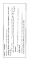
- FIG. 4 is a specification modification example (1) according to the first operation example in the embodiment of the present invention.
- FIG. 4 shows an example of changing the specifications of the DCI format for scheduling the PUSCH.
- the BWP indicator (Bandwidth part indicator) included in the DCI format 0_1 has a length of 0, 1 or 2 bits and is determined based on n BWP, RRC which is the number of ULBWP set from the upper layer excluding the initial ULBWP. It The bit length of the BWP indicator is determined by ceil(log 2 (n BWP )). The n BWP is determined according to the value of n BWP,RRC as shown in a) and b) below.
- n BWP,RRC n BWP,RRC +1
- the BWP indicator is equivalent to the upper layer parameter BWP-Id in ascending order.
- BWP-UplinkCommon is set to the initial ULBWP, that is, when BWP-UplinkDedicated is not set to the initial ULBWP, the user device 20 ignores the notified BWP indicator “00”.
- n BWP, if not the RRC ⁇ 3, n BWP n BWP, RRC In this case, the BWP indicator is defined as shown in Table 1.
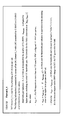
- FIG. 5 is a specification modification example (2) according to the first operation example in the embodiment of the present invention.
- FIG. 5 shows an example of changing the specifications of the DCI format for scheduling PDSCH.
- the BWP indicator (Bandwidth part indicator) included in the DCI format 1_1 has a length of 0, 1 or 2 bits, and is determined based on n BWP, RRC which is the number of DLBWP set from the upper layer excluding the initial DLBWP. It The bit length of the BWP indicator is determined by ceil(log 2 (n BWP )). The n BWP is determined according to the value of n BWP,RRC as shown in a) and b) below.
- n BWP,RRC n BWP,RRC +1
- the BWP indicator is equivalent to the upper layer parameter BWP-Id in ascending order.
- BWP-DownlinkCommon is set to the initial DLBWP, that is, when BWP-DownlinkDedicated is not set to the initial DLBWP
- the user device 20 ignores the notified BWP indicator “00”.
- n BWP, if not the RRC ⁇ 3, n BWP n BWP, RRC In this case, the BWP indicator is defined as shown in Table 1.
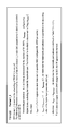
- FIG. 6 is a specification modification example (1) according to the second operation example in the embodiment of the present invention.
- FIG. 6 shows an example of changing the specifications of the DCI format for scheduling PUSCH.
- the BWP indicator (Bandwidth part indicator) included in the DCI format 0_1 is 0, 1 or 2 bits long, and is determined based on n BWP, RRC which is the number of ULBWP set from the upper layer excluding the initial ULBWP. It The bit length of the BWP indicator is determined by ceil(log 2 (n BWP )). The n BWP is determined according to the value of n BWP,RRC as shown in a) and b) below.
- n BWP n BWP,RRC +1
- BWP indicator is equivalent to the upper layer parameter BWP-Id in ascending order.
- FIG. 7 is a specification modification example (2) according to the second operation example in the embodiment of the present invention.
- FIG. 7 shows an example of changing the specifications of the DCI format for scheduling PDSCH.
- the BWP indicator (Bandwidth part indicator) included in the DCI format 1_1 has a length of 0, 1 or 2 bits, and is determined based on n BWP, RRC which is the number of DLBWP set from the upper layer excluding the initial DLBWP. It The bit length of the BWP indicator is determined by ceil(log 2 (n BWP )). The n BWP is determined according to the value of n BWP,RRC as shown in a) and b) below.
- n BWP n BWP,RRC +1
- BWP indicator is equivalent to the upper layer parameter BWP-Id in ascending order.
- the BWP indicator is defined as shown in Table 1. Therefore, the invalid ULBWP ID #0 will not be mapped to the BWP indicator.
- the BWP indicator is defined as shown in Table 1. Therefore, the invalid DLBWP ID #0 will not be mapped to the BWP indicator.
- FIG. 8 is a specification modification example (1) according to the third operation example in the embodiment of the present invention.
- FIG. 8 shows an example of changing the specifications of the DCI format for scheduling PUSCH.
- the BWP indicator (Bandwidth part indicator) included in the DCI format 0_1 has a length of 0, 1 or 2 bits and is determined based on n BWP which is the number of ULBWPs set from the upper layer including the initial ULBWP.
- the bit length of the BWP indicator is determined by min(ceil(log 2 (n BWP ),2).
- the following a) b) determines the operation according to the value of n BWP .
- FIG. 9 is a specification modification example (2) according to the third operation example in the embodiment of the present invention.
- FIG. 9 shows an example of changing the specifications of the DCI format for scheduling PDSCH.
- the BWP indicator (Bandwidth part indicator) included in the DCI format 1_1 has a length of 0, 1 or 2 bits and is determined based on n BWP which is the number of DLBWP set from the upper layer including the initial ULBWP.
- the bit length of the BWP indicator is determined by min(ceil(log 2 (n BWP ),2).
- the following a) b) determines the operation according to the value of n BWP .
- FIG. 10 is a specification modification example (1) according to the fourth operation example in the embodiment of the present invention.
- FIG. 4 shows an example of changing the specifications of the DCI format for scheduling the PUSCH.
- the BWP indicator (Bandwidth part indicator) included in the DCI format 0_1 is 0, 1 or 2 bits long, and is determined based on n BWP, RRC which is the number of ULBWP set from the upper layer excluding the initial ULBWP. It The bit length of the BWP indicator is determined by ceil(log 2 (n BWP )). n BWP is determined according to the values of n BWP and RRC as shown in a) b) c) below.
- FIG. 11 is a specification modification example (2) according to the first operation example in the embodiment of the present invention.
- FIG. 5 shows an example of changing the specifications of the DCI format for scheduling PDSCH.
- the BWP indicator (Bandwidth part indicator) included in the DCI format 1_1 has a length of 0, 1 or 2 bits, and is determined based on n BWP, RRC which is the number of DLBWP set from the upper layer excluding the initial DLBWP. It The bit length of the BWP indicator is determined by ceil(log 2 (n BWP )). n BWP is determined according to the values of n BWP and RRC as shown in a) b) c) below.
- the user device 20 when the user device 20 receives the BWP indicator included in the DCI format, the user device 20 can specify the BWP based on the BWP indicator and apply the corresponding communication setting to the BWP.
- the base station device 10 and the user device 20 include a function for implementing the above-described embodiment. However, each of the base station device 10 and the user device 20 may have only some of the functions in the embodiment.
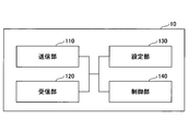
- FIG. 12 is a diagram showing an example of a functional configuration of the base station device 10.
- the base station device 10 includes a transmission unit 110, a reception unit 120, a setting unit 130, and a control unit 140.
- the functional configuration shown in FIG. 12 is merely an example. As long as the operation according to the embodiment of the present invention can be executed, the function classification and the names of the function units may be any names.
- the transmitting unit 110 includes a function of generating a signal to be transmitted to the user device 20 side and wirelessly transmitting the signal.
- the receiving unit 120 includes a function of receiving various signals transmitted from the user device 20 and acquiring, for example, information of a higher layer from the received signals. Further, the transmission unit 110 has a function of transmitting NR-PSS, NR-SSS, NR-PBCH, DL/UL control signals, etc. to the user apparatus 20.
- the setting unit 130 stores preset setting information and various setting information to be transmitted to the user device 20 in the storage device, and reads it from the storage device as necessary.
- the content of the setting information is, for example, the communication setting related to the cell of the user device 20, the communication setting related to BWP, and the like.
- the control unit 140 performs the process related to the communication setting related to the cell or the BWP of the user device 20, as described in the embodiment.
- the functional unit related to signal transmission in the control unit 140 may be included in the transmission unit 110, and the functional unit related to signal reception in the control unit 140 may be included in the reception unit 120.
- FIG. 13 is a diagram illustrating an example of a functional configuration of the user device 20.
- the user device 20 includes a transmission unit 210, a reception unit 220, a setting unit 230, and a control unit 240.
- the functional configuration shown in FIG. 13 is merely an example. As long as the operation according to the embodiment of the present invention can be executed, the function classification and the names of the function units may be any names.
- the transmitting unit 210 creates a transmission signal from the transmission data and wirelessly transmits the transmission signal.
- the reception unit 220 wirelessly receives various signals and acquires signals of higher layers from the received physical layer signals. Further, the receiving unit 220 has a function of receiving NR-PSS, NR-SSS, NR-PBCH, DL/UL/SL control signals and the like transmitted from the base station apparatus 10.
- the transmission unit 210 performs P2CH communication to other user apparatuses 20 by using PSCCH (Physical Sidelink Control Channel), PSSCH (Physical Sidelink Shared Channel), PSDCH (Physical Sidelink Discovery Channel), and PSBCH (Physical Sidelink Broadcast Channel). ) Etc., and the receiving part 120 receives PSCCH, PSSCH, PSDCH, PSBCH, etc. from the other user apparatus 20.
- PSCCH Physical Sidelink Control Channel
- PSSCH Physical Sidelink Shared Channel
- PSDCH Physical Sidelink Discovery Channel
- PSBCH Physical Sidelink Broadcast Channel
- the setting unit 230 stores various setting information received from the base station device 10 or the user device 20 by the receiving unit 220 in a storage device, and reads it from the storage device as necessary.
- the setting unit 230 also stores preset setting information.
- the contents of the setting information are, for example, communication settings related to cells, communication settings related to BWP, and the like.
- the control unit 240 controls the communication to which the BWP is applied based on the communication setting acquired from the base station device 10, as described in the embodiment.
- the functional unit related to signal transmission in the control unit 240 may be included in the transmission unit 210, and the functional unit related to signal reception in the control unit 240 may be included in the reception unit 220.
- each functional block may be realized by using one device physically or logically coupled, or directly or indirectly (for example, two or more devices physically or logically separated). , Wired, wireless, etc.) and may be implemented using these multiple devices.
- the functional block may be realized by combining the one device or the plurality of devices with software.
- Functions include judgment, decision, judgment, calculation, calculation, processing, derivation, investigation, search, confirmation, reception, transmission, output, access, resolution, selection, selection, establishment, comparison, assumption, expectation, observation, Broadcasting, notifying, communicating, forwarding, configuration, reconfiguring, allocating, mapping, assigning, etc., but not limited to these.
- I can't.
- functional blocks (components) that function transmission are called a transmitting unit and a transmitter.
- the implementation method is not particularly limited.
- the base station device 10, the user device 20, and the like according to the embodiment of the present disclosure may function as a computer that performs the process of the wireless communication method of the present disclosure.
- FIG. 14 is a diagram illustrating an example of a hardware configuration of the base station device 10 and the user device 20 according to the embodiment of the present disclosure.
- the base station device 10 and the user device 20 described above are physically configured as a computer device including a processor 1001, a storage device 1002, an auxiliary storage device 1003, a communication device 1004, an input device 1005, an output device 1006, a bus 1007, and the like. May be done.
- the word “apparatus” can be read as a circuit, device, unit, or the like.
- the hardware configurations of the base station device 10 and the user device 20 may be configured to include one or a plurality of each device illustrated in the figure, or may be configured not to include some devices.
- Each function in the base station device 10 and the user device 20 causes a predetermined software (program) to be loaded onto hardware such as the processor 1001, the storage device 1002, etc., so that the processor 1001 performs an arithmetic operation and the communication by the communication device 1004. It is realized by controlling and/or controlling at least one of reading and writing of data in the storage device 1002 and the auxiliary storage device 1003.
- the processor 1001 operates an operating system to control the entire computer, for example.
- the processor 1001 may be configured by a central processing unit (CPU) including an interface with peripheral devices, a control device, a calculation device, a register, and the like.
- CPU central processing unit
- the control unit 140 and the control unit 240 described above may be realized by the processor 1001.
- the processor 1001 reads a program (program code), software module, data, or the like from at least one of the auxiliary storage device 1003 and the communication device 1004 into the storage device 1002, and executes various processes according to these.
- a program that causes a computer to execute at least part of the operations described in the above-described embodiments is used.
- the control unit 140 of the base station device 10 illustrated in FIG. 12 may be realized by a control program stored in the storage device 1002 and operated by the processor 1001.
- the control unit 240 of the user device 20 illustrated in FIG. 13 may be realized by a control program stored in the storage device 1002 and operated by the processor 1001.
- the various processes described above are executed by one processor 1001, they may be executed simultaneously or sequentially by two or more processors 1001.
- the processor 1001 may be implemented by one or more chips.
- the program may be transmitted from the network via an electric communication line.
- the storage device 1002 is a computer-readable recording medium, and is, for example, at least one of ROM (Read Only Memory), EPROM (Erasable Programmable ROM), EEPROM (Electrically Erasable Programmable ROM), RAM (Random Access Memory), and the like. It may be configured.
- the storage device 1002 may be called a register, a cache, a main memory (main storage device), or the like.
- the storage device 1002 can store an executable program (program code), a software module, or the like for implementing the communication method according to the embodiment of the present disclosure.
- the auxiliary storage device 1003 is a computer-readable recording medium, and is, for example, an optical disk such as a CD-ROM (Compact Disc ROM), a hard disk drive, a flexible disk, a magneto-optical disk (for example, a compact disk, a digital versatile disk, a Blu disk). -Ray disk), smart card, flash memory (eg card, stick, key drive), floppy disk, magnetic strip, etc.
- the above-mentioned storage medium may be, for example, a database including at least one of the storage device 1002 and the auxiliary storage device 1003, a server, or another appropriate medium.
- the communication device 1004 is hardware (transmission/reception device) for performing communication between computers via at least one of a wired network and a wireless network, and is also called, for example, a network device, a network controller, a network card, a communication module, or the like.
- the communication device 1004 includes, for example, a high frequency switch, a duplexer, a filter, a frequency synthesizer, etc. in order to realize at least one of a frequency division duplex (FDD: Frequency Division Duplex) and a time division duplex (TDD: Time Division Duplex). May be composed of
- FDD Frequency Division Duplex
- TDD Time Division Duplex
- the transmitter/receiver may be implemented by physically or logically separating the transmitter and the receiver.
- the input device 1005 is an input device (for example, a keyboard, a mouse, a microphone, a switch, a button, a sensor, etc.) that receives an input from the outside.
- the output device 1006 is an output device (for example, a display, a speaker, an LED lamp, etc.) that outputs to the outside.
- the input device 1005 and the output device 1006 may be integrated (for example, a touch panel).
- each device such as the processor 1001 and the storage device 1002 is connected by a bus 1007 for communicating information.
- the bus 1007 may be configured by using a single bus, or may be configured by using a different bus for each device.
- the base station device 10 and the user device 20 include a microprocessor, a digital signal processor (DSP: Digital Signal Processor), an ASIC (Application Specific Integrated Circuit), a PLD (Programmable Logic Device), an FPGA (Field Programmable Gate Array), and the like. It may be configured to include hardware, and the hardware may implement some or all of the functional blocks. For example, the processor 1001 may be implemented using at least one of these hardware.
- DSP Digital Signal Processor
- ASIC Application Specific Integrated Circuit
- PLD Programmable Logic Device
- FPGA Field Programmable Gate Array
- the information that specifies the BWP (Bandwidth part) and the reception unit that receives the communication settings applied to the BWP from the base station device and the information that specifies the BWP.
- a user apparatus having a communication unit adapted to communicate with the base station apparatus is provided.
- the user device 20 when the user device 20 receives the BWP indicator included in the DCI format, the user device 20 can specify the BWP based on the BWP indicator and apply the corresponding communication setting to the BWP. That is, in the wireless communication system, it is possible to set the communication to which BWP is applied.
- the control unit determines the predetermined information of the BWP. The value of may be ignored. With this configuration, the user device 20 can ignore the received BWP indicator when it specifies an invalid BWP.
- the predetermined value of the information designating the BWP may be a value designating an invalid BWP.
- the user device 20 can ignore the received BWP indicator when it specifies an invalid BWP.
- the information specifying the BWP does not specify the initial BWP and the communication settings applied to the BWP corresponding to the initial BWP are both the link common setting and the link individual setting, the information specifying the BWP is invalid.
- a transmitter that transmits information specifying BWP (Bandwidth part) and communication settings applied to BWP to a user apparatus, information specifying the BWP, and used for initial connection. Based on the communication setting applied to the BWP corresponding to the initial BWP, and the user device applying the communication setting applied to the BWP corresponding to the specified BWP there is provided a base station device having a communication unit for communicating with.
- the user device 20 when the user device 20 receives the BWP indicator included in the DCI format, the user device 20 can specify the BWP based on the BWP indicator and apply the corresponding communication setting to the BWP. That is, in the wireless communication system, it is possible to set the communication to which BWP is applied.
- the operation of the plurality of functional units may be physically performed by one component, or the operation of one functional unit may be physically performed by the plurality of components.
- the order of processing may be changed as long as there is no contradiction.
- the base station apparatus 10 and the user apparatus 20 are described using functional block diagrams for convenience of processing description, such an apparatus may be realized by hardware, software, or a combination thereof.
- the software operated by the processor included in the base station device 10 according to the embodiment of the present invention and the software operated by the processor included in the user device 20 according to the embodiment of the present invention are respectively a random access memory (RAM), a flash memory, and a read memory. It may be stored in a dedicated memory (ROM), EPROM, EEPROM, register, hard disk (HDD), removable disk, CD-ROM, database, server, or any other suitable storage medium.
- the notification of information is not limited to the mode/embodiment described in the present disclosure, and may be performed using another method.
- information is notified by physical layer signaling (for example, DCI (Downlink Control Information), UCI (Uplink Control Information)), upper layer signaling (for example, RRC (Radio Resource Control) signaling, MAC (Medium Access Control) signaling, It may be implemented by broadcast information (MIB (Master Information Block), SIB (System Information Block)), other signals, or a combination thereof, and RRC signaling may be called an RRC message, for example, RRC message. It may be a connection setup (RRC Connection Setup) message, an RRC connection reconfiguration message, or the like.
- LTE Long Term Evolution
- LTE-A Long Term Evolution-Advanced
- SUPER 3G IMT-Advanced
- 4G 4th generation mobile communication system
- 5G 5th generation mobile communication system
- FRA Fluture Radio Access
- NR new Radio
- W-CDMA registered trademark
- GSM registered trademark
- CDMA2000 Code Division Multiple Access 2000
- UMB Universal Mobile Broadband
- IEEE 802.11 Wi-Fi (registered trademark)
- IEEE 802.16 WiMAX (registered trademark)
- IEEE 802.20 UWB (Ultra-WideBand
- Bluetooth registered trademark
- It may be applied to at least one of the next-generation systems. Further, a plurality of systems may be combined and applied (for example, a combination of at least one of LTE and LTE-A and 5G).
- the specific operation that is performed by the base station device 10 in this specification may be performed by its upper node in some cases.
- various operations performed for communication with the user device 20 are other than the base station device 10 and the base station device 10. It is clear that it can be performed by at least one of the network nodes of (for example, but not limited to, MME or S-GW, etc.).
- the other network node may be a combination of a plurality of other network nodes (for example, MME and S-GW). Good.
- Information, signals, etc. described in the present disclosure may be output from the upper layer (or lower layer) to the lower layer (or upper layer). Input/output may be performed via a plurality of network nodes.
- Information that has been input and output may be stored in a specific location (for example, memory), or may be managed using a management table. Information that is input/output may be overwritten, updated, or added. The output information and the like may be deleted. The input information and the like may be transmitted to another device.
- the determination according to the present disclosure may be performed based on a value (0 or 1) represented by 1 bit, may be performed based on a boolean value (Boolean: true or false), and may be performed by comparing numerical values (for example, , Comparison with a predetermined value).
- software, instructions, information, etc. may be transmitted and received via a transmission medium.
- the software uses a wired technology (coaxial cable, optical fiber cable, twisted pair, digital subscriber line (DSL: Digital Subscriber Line), etc.) and/or wireless technology (infrared, microwave, etc.) websites, When sent from a server, or other remote source, at least one of these wired and wireless technologies are included within the definition of transmission medium.
- wired technology coaxial cable, optical fiber cable, twisted pair, digital subscriber line (DSL: Digital Subscriber Line), etc.
- wireless technology infrared, microwave, etc.
- data, instructions, commands, information, signals, bits, symbols, chips, etc. that may be referred to throughout the above description include voltage, current, electromagnetic waves, magnetic fields or magnetic particles, optical fields or photons, or any of these. May be represented by a combination of
- At least one of the channel and the symbol may be a signal (signaling).
- the signal may also be a message.
- a component carrier CC:Component Carrier
- CC Component Carrier
- system and “network” used in this disclosure are used interchangeably.
- the information, parameters, etc. described in the present disclosure may be represented by using an absolute value, may be represented by using a relative value from a predetermined value, or by using other corresponding information. May be represented.
- the radio resources may be those indicated by the index.
- base station Base Station
- radio base station base station
- base station device fixed station
- NodeB NodeB
- eNodeB eNodeB
- GNB nodeB
- Access point access point
- transmission point transmission point
- reception point transmission/reception point
- cell cell
- vector Terms such as “cell group”, “carrier”, “component carrier” may be used interchangeably.
- a base station may be referred to by terms such as macro cell, small cell, femto cell, and pico cell.
- a base station can accommodate one or more (eg, three) cells.
- the entire coverage area of the base station can be divided into multiple smaller areas, each smaller area being a base station subsystem (eg, a small indoor base station (RRH: Communication service can also be provided by Remote Radio Head.
- RRH small indoor base station
- the term "cell” or “sector” means a part or the whole of the coverage area of at least one of the base station and the base station subsystem that perform communication service in this coverage. Refers to.
- MS Mobile Station
- UE User Equipment
- Mobile stations are defined by those skilled in the art as subscriber stations, mobile units, subscriber units, wireless units, remote units, mobile devices, wireless devices, wireless communication devices, remote devices, mobile subscriber stations, access terminals, mobile terminals, wireless. It may also be referred to as a terminal, remote terminal, handset, user agent, mobile client, client, or some other suitable term.
- At least one of the base station and the mobile station may be called a transmission device, a reception device, a communication device, or the like.
- at least one of the base station and the mobile station may be a device mounted on a mobile body, the mobile body itself, or the like.
- the moving body may be a vehicle (eg, car, airplane, etc.), an unmanned moving body (eg, drone, self-driving car, etc.), or a robot (manned or unmanned). ).
- at least one of the base station and the mobile station includes a device that does not necessarily move during communication operation.
- at least one of the base station and the mobile station may be an IoT (Internet of Things) device such as a sensor.
- IoT Internet of Things
- the base station in the present disclosure may be replaced by the user terminal.
- the communication between the base station and the user terminal is replaced with communication between a plurality of user devices 20 (eg, may be referred to as D2D (Device-to-Device), V2X (Vehicle-to-Everything), etc.)
- a plurality of user devices 20 eg, may be referred to as D2D (Device-to-Device), V2X (Vehicle-to-Everything), etc.
- the user device 20 may have the function of the base station device 10 described above.
- the words such as “up” and “down” may be replaced with the words corresponding to the communication between terminals (for example, “side”).
- the uplink channel and the downlink channel may be replaced with the side channel.
- the user terminal in the present disclosure may be replaced by the base station.
- the base station may have the function of the above-mentioned user terminal.
- determining and “determining” as used in this disclosure may encompass a wide variety of actions.
- “Judgment” and “decision” are, for example, judgment, calculating, computing, processing, deriving, investigating, and looking up, search, inquiry. (Eg, searching in a table, a database, or another data structure), considering ascertaining as “judging” or “deciding” may be included.
- “decision” and “decision” include receiving (eg, receiving information), transmitting (eg, transmitting information), input (input), output (output), access (accessing) (for example, accessing data in a memory) may be regarded as “judging” and “deciding”.
- judgment and “decision” are considered to be “judgment” and “decision” when things such as resolving, selecting, selecting, establishing, establishing, and comparing are done. May be included. That is, the “judgment” and “decision” may include considering some action as “judgment” and “decision”. In addition, “determination (decision)” may be read as “assuming,” “expecting,” “considering,” and the like.
- connection means any direct or indirect connection or coupling between two or more elements, and It may include the presence of one or more intermediate elements between two elements that are “connected” or “coupled”.
- the connections or connections between the elements may be physical, logical, or a combination thereof.
- connection may be read as “access”.
- two elements are in the radio frequency domain, with at least one of one or more wires, cables and printed electrical connections, and as some non-limiting and non-exhaustive examples. , Can be considered to be “connected” or “coupled” to each other, such as with electromagnetic energy having wavelengths in the microwave and light (both visible and invisible) regions.
- the reference signal may be abbreviated as RS (Reference Signal), or may be referred to as a pilot (Pilot) depending on the applied standard.
- RS Reference Signal
- Pilot pilot
- the phrase “based on” does not mean “based only on,” unless expressly specified otherwise. In other words, the phrase “based on” means both "based only on” and “based at least on.”
- references to elements using the designations “first,” “second,” etc. as used in this disclosure does not generally limit the amount or order of those elements. These designations may be used in this disclosure as a convenient way to distinguish between two or more elements. Thus, references to the first and second elements do not mean that only two elements may be employed, or that the first element must precede the second element in any way.
- a radio frame may be composed of one or more frames in the time domain. Each frame or frames in the time domain may be referred to as a subframe. A subframe may also be composed of one or more slots in the time domain. The subframe may have a fixed time length (for example, 1 ms) that does not depend on numerology.
- Numerology may be a communication parameter applied to at least one of transmission and reception of a certain signal or channel.
- Numerology includes, for example, subcarrier spacing (SCS: SubCarrier Spacing), bandwidth, symbol length, cyclic prefix length, transmission time interval (TTI: Transmission Time Interval), number of symbols per TTI, radio frame configuration, transceiver At least one of a specific filtering process performed in the frequency domain and a specific windowing process performed by the transceiver in the time domain may be shown.
- a slot may be composed of one or more symbols (OFDM (Orthogonal Frequency Division Multiplexing) symbol, SC-FDMA (Single Carrier Frequency Division Multiple Access) symbol, etc.) in the time domain.
- a slot may be a time unit based on numerology.
- a slot may include multiple minislots. Each minislot may be composed of one or more symbols in the time domain. The minislot may also be called a subslot. Minislots may be configured with a smaller number of symbols than slots.
- a PDSCH (or PUSCH) transmitted in a time unit larger than a minislot may be referred to as PDSCH (or PUSCH) mapping type A.
- the PDSCH (or PUSCH) transmitted using the minislot may be referred to as PDSCH (or PUSCH) mapping type B.
- Radio frame, subframe, slot, minislot, and symbol all represent the time unit for signal transmission. Radio frames, subframes, slots, minislots, and symbols may have different names corresponding to them.
- one subframe may be called a transmission time interval (TTI)
- TTI transmission time interval
- TTI transmission time interval
- TTI transmission time interval
- TTI transmission time interval
- TTI means, for example, a minimum time unit of scheduling in wireless communication.
- the base station performs scheduling to allocate radio resources (frequency bandwidth that can be used in each user device 20, transmission power, etc.) to each user device 20 in units of TTI.
- the definition of TTI is not limited to this.
- the TTI may be a transmission time unit such as a channel-encoded data packet (transport block), a code block, a codeword, or a processing unit such as scheduling or link adaptation.
- transport block channel-encoded data packet
- code block code block
- codeword codeword
- processing unit such as scheduling or link adaptation.
- one slot or one minislot is called a TTI
- one or more TTIs may be the minimum time unit for scheduling.
- the number of slots (minislot number) that constitutes the minimum time unit of the scheduling may be controlled.
- a TTI having a time length of 1 ms may be called a normal TTI (TTI in LTE Rel. 8-12), a normal TTI, a long TTI, a normal subframe, a normal subframe, a long subframe, a slot, or the like.
- a TTI shorter than the normal TTI may be called a shortened TTI, a short TTI, a partial TTI (partial or fractional TTI), a shortened subframe, a short subframe, a minislot, a subslot, a slot, and the like.
- a long TTI (eg, normal TTI, subframe, etc.) may be read as a TTI having a time length of more than 1 ms, and a short TTI (eg, shortened TTI, etc.) is less than the TTI length of the long TTI and 1 ms. It may be read as a TTI having the above TTI length.
- a resource block is a resource allocation unit in the time domain and the frequency domain, and may include one or a plurality of continuous subcarriers in the frequency domain.
- the number of subcarriers included in the RB may be the same regardless of the numerology, and may be 12, for example.
- the number of subcarriers included in the RB may be determined based on numerology.
- the time domain of RB may include one or more symbols, and may be one slot, one minislot, one subframe, or one TTI in length.
- Each 1 TTI, 1 subframe, etc. may be configured with one or a plurality of resource blocks.
- one or more RBs are a physical resource block (PRB: Physical RB), subcarrier group (SCG: Sub-Carrier Group), resource element group (REG: Resource Element Group), PRB pair, RB pair, etc. May be called.
- PRB Physical resource block
- SCG Sub-Carrier Group
- REG Resource Element Group
- PRB pair RB pair, etc. May be called.
- the resource block may be composed of one or more resource elements (RE: Resource Element).
- RE Resource Element
- one RE may be a radio resource area of one subcarrier and one symbol.
- a bandwidth part (may be called a partial bandwidth) may represent a subset of consecutive common RBs (common resource blocks) for a certain numerology in a certain carrier.
- the common RB may be specified by the index of the RB based on the common reference point of the carrier.
- PRBs may be defined in a BWP and numbered within that BWP.
- BWP may include BWP for UL (UL BWP) and BWP for DL (DL BWP).
- BWP may include BWP for UL (UL BWP) and BWP for DL (DL BWP).
- One or more BWPs may be configured in one carrier for the UE.
- At least one of the configured BWPs may be active, and the UE does not have to expect to send and receive a given signal/channel outside the active BWP.
- “cell”, “carrier”, and the like in the present disclosure may be read as “BWP”.
- the structure of the radio frame, subframe, slot, minislot, symbol, etc. described above is merely an example.
- the number of subframes included in a radio frame, the number of slots per subframe or radio frame, the number of minislots included in a slot, the number of symbols and RBs included in a slot or minislot, and included in RBs The number of subcarriers, the number of symbols in the TTI, the symbol length, the cyclic prefix (CP: Cyclic Prefix) length, and the like can be variously changed.
- the term “A and B are different” may mean “A and B are different from each other”.
- the term may mean that “A and B are different from C”.
- the terms “remove”, “coupled” and the like may be construed as “different” as well.
- the notification of the predetermined information (for example, the notification of “being X”) is not limited to the explicit notification, and is performed implicitly (for example, the notification of the predetermined information is not performed). Good.
- the transmission unit 210 and the reception unit 220 are examples of the communication unit.
- the BWP indicator is an example of information designating BWP.
- BWP-UplinkCommon is an example of the uplink common setting.
- BWP-DownlinkCommon is an example of downlink common settings.
- BWP-UplinkDedicated is an example of uplink individual setting.
- BWP-DownlinkDedicated is an example of downlink individual setting.
- the transmission unit 110 and the reception unit 120 are an example of a communication unit.
- base station device 110 transmission unit 120 reception unit 130 setting unit 140 control unit 20 user device 210 transmission unit 220 reception unit 230 setting unit 240 control unit 1001 processor 1002 storage device 1003 auxiliary storage device 1004 communication device 1005 input device 1006 output device
Landscapes
- Engineering & Computer Science (AREA)
- Computer Networks & Wireless Communication (AREA)
- Signal Processing (AREA)
- Mobile Radio Communication Systems (AREA)
Abstract
La présente invention concerne un dispositif utilisateur comprenant : une unité de réception qui reçoit des informations désignant une partie de bande passante (BWP) et un réglage de communication appliqué à la BWP à partir d'un dispositif de station de base; une unité de commande qui spécifie la BWP à utiliser, sur la base des informations désignant la BWP et du réglage de communication appliqué à la BWP correspondant à une BWP initiale utilisée pour la connexion initiale; et une unité de communication qui communique avec le dispositif de station de base en appliquant un réglage de communication appliqué à la BWP correspondant à la BWP spécifiée.
Priority Applications (1)
| Application Number | Priority Date | Filing Date | Title |
|---|---|---|---|
| PCT/JP2019/004222 WO2020161824A1 (fr) | 2019-02-06 | 2019-02-06 | Dispositif utilisateur et dispositif de station de base |
Applications Claiming Priority (1)
| Application Number | Priority Date | Filing Date | Title |
|---|---|---|---|
| PCT/JP2019/004222 WO2020161824A1 (fr) | 2019-02-06 | 2019-02-06 | Dispositif utilisateur et dispositif de station de base |
Publications (1)
| Publication Number | Publication Date |
|---|---|
| WO2020161824A1 true WO2020161824A1 (fr) | 2020-08-13 |
Family
ID=71947728
Family Applications (1)
| Application Number | Title | Priority Date | Filing Date |
|---|---|---|---|
| PCT/JP2019/004222 WO2020161824A1 (fr) | 2019-02-06 | 2019-02-06 | Dispositif utilisateur et dispositif de station de base |
Country Status (1)
| Country | Link |
|---|---|
| WO (1) | WO2020161824A1 (fr) |
Cited By (1)
| Publication number | Priority date | Publication date | Assignee | Title |
|---|---|---|---|---|
| WO2022193195A1 (fr) * | 2021-03-17 | 2022-09-22 | 北京小米移动软件有限公司 | Procédé de configuration de partie de bande passante, appareil de configuration de partie de bande passante et support d'enregistrement |
-
2019
- 2019-02-06 WO PCT/JP2019/004222 patent/WO2020161824A1/fr active Application Filing
Non-Patent Citations (2)
| Title |
|---|
| HUAWEI ET AL.: "BWP ID Issue", 3GPP TSG RAN WG2 #103 , 2018.08.24 , R2-1812593, 9 April 2019 (2019-04-09), XP051522188, Retrieved from the Internet <URL:http://www.3gpp.org/ftp/tsg_ran/WG2_RL2/TSGR2_103/Docs/R2-1812593.zip> * |
| NOKIA ET AL.: "Differences of BWP configuration options 1 and 2", 3GPP TSG RAN WG2 #103, 2018.08.24 , R2-1811372, 9 April 2019 (2019-04-09), XP051521028, Retrieved from the Internet <URL:http://www.3gpp.org/ftp/tsg_ran/WG2_RL2/TSGR2_103/Docs/R2-1811372.zip> * |
Cited By (1)
| Publication number | Priority date | Publication date | Assignee | Title |
|---|---|---|---|---|
| WO2022193195A1 (fr) * | 2021-03-17 | 2022-09-22 | 北京小米移动软件有限公司 | Procédé de configuration de partie de bande passante, appareil de configuration de partie de bande passante et support d'enregistrement |
Similar Documents
| Publication | Publication Date | Title |
|---|---|---|
| JP2024024117A (ja) | 端末及び通信方法 | |
| JP2023156440A (ja) | 端末、基地局及び通信方法 | |
| WO2020230201A1 (fr) | Dispositif utilisateur et dispositif de station de base | |
| WO2020170405A1 (fr) | Équipement utilisateur et appareil de station de base | |
| JP7369211B2 (ja) | 端末、基地局及び通信方法 | |
| WO2021140673A1 (fr) | Terminal et procédé de communication | |
| JP7073529B2 (ja) | 端末、基地局及び通信方法 | |
| WO2020161824A1 (fr) | Dispositif utilisateur et dispositif de station de base | |
| WO2020171182A1 (fr) | Dispositif utilisateur et dispositif de station de base | |
| WO2021038920A1 (fr) | Terminal, station de base et procédé de communication | |
| JP7170842B2 (ja) | ユーザ装置及び基地局装置 | |
| WO2020170445A1 (fr) | Dispositif utilisateur et dispositif de station de base | |
| WO2020157874A1 (fr) | Dispositif utilisateur et dispositif de station de base | |
| WO2020157873A1 (fr) | Dispositif d'utilisateur et dispositif de station de base | |
| WO2020194636A1 (fr) | Équipement utilisateur | |
| WO2020157986A1 (fr) | Dispositif utilisateur et dispositif de station de base | |
| WO2020090069A1 (fr) | Dispositif utilisateur et dispositif de station de base | |
| WO2020157987A1 (fr) | Dispositif d'utilisateur et dispositif de station de base | |
| JP7373559B2 (ja) | ユーザ装置及び無線通信システム | |
| JP7491905B2 (ja) | 端末、基地局装置、通信方法及びシステム | |
| JP7364679B2 (ja) | 端末、通信システム及び通信方法 | |
| WO2022044558A1 (fr) | Terminal, station de base et procédé de communication | |
| WO2022038919A1 (fr) | Terminal et procédé de communication | |
| WO2021140676A1 (fr) | Terminal et procédé de communication | |
| WO2021161455A1 (fr) | Terminal et procédé de transmission d'informations de capacité |
Legal Events
| Date | Code | Title | Description |
|---|---|---|---|
| 121 | Ep: the epo has been informed by wipo that ep was designated in this application |
Ref document number: 19914252 Country of ref document: EP Kind code of ref document: A1 |
|
| NENP | Non-entry into the national phase |
Ref country code: DE |
|
| 122 | Ep: pct application non-entry in european phase |
Ref document number: 19914252 Country of ref document: EP Kind code of ref document: A1 |
|
| NENP | Non-entry into the national phase |
Ref country code: JP |