WO2020230201A1 - Dispositif utilisateur et dispositif de station de base - Google Patents
Dispositif utilisateur et dispositif de station de base Download PDFInfo
- Publication number
- WO2020230201A1 WO2020230201A1 PCT/JP2019/018784 JP2019018784W WO2020230201A1 WO 2020230201 A1 WO2020230201 A1 WO 2020230201A1 JP 2019018784 W JP2019018784 W JP 2019018784W WO 2020230201 A1 WO2020230201 A1 WO 2020230201A1
- Authority
- WO
- WIPO (PCT)
- Prior art keywords
- base station
- band combination
- report
- information
- user device
- Prior art date
Links
Images


Classifications
-
- H—ELECTRICITY
- H04—ELECTRIC COMMUNICATION TECHNIQUE
- H04W—WIRELESS COMMUNICATION NETWORKS
- H04W76/00—Connection management
- H04W76/10—Connection setup
- H04W76/15—Setup of multiple wireless link connections
- H04W76/16—Involving different core network technologies, e.g. a packet-switched [PS] bearer in combination with a circuit-switched [CS] bearer
-
- H—ELECTRICITY
- H04—ELECTRIC COMMUNICATION TECHNIQUE
- H04L—TRANSMISSION OF DIGITAL INFORMATION, e.g. TELEGRAPHIC COMMUNICATION
- H04L5/00—Arrangements affording multiple use of the transmission path
- H04L5/0001—Arrangements for dividing the transmission path
- H04L5/0003—Two-dimensional division
- H04L5/0005—Time-frequency
- H04L5/0007—Time-frequency the frequencies being orthogonal, e.g. OFDM(A), DMT
- H04L5/001—Time-frequency the frequencies being orthogonal, e.g. OFDM(A), DMT the frequencies being arranged in component carriers
-
- H—ELECTRICITY
- H04—ELECTRIC COMMUNICATION TECHNIQUE
- H04L—TRANSMISSION OF DIGITAL INFORMATION, e.g. TELEGRAPHIC COMMUNICATION
- H04L5/00—Arrangements affording multiple use of the transmission path
- H04L5/003—Arrangements for allocating sub-channels of the transmission path
- H04L5/0032—Distributed allocation, i.e. involving a plurality of allocating devices, each making partial allocation
- H04L5/0035—Resource allocation in a cooperative multipoint environment
-
- H—ELECTRICITY
- H04—ELECTRIC COMMUNICATION TECHNIQUE
- H04L—TRANSMISSION OF DIGITAL INFORMATION, e.g. TELEGRAPHIC COMMUNICATION
- H04L5/00—Arrangements affording multiple use of the transmission path
- H04L5/003—Arrangements for allocating sub-channels of the transmission path
- H04L5/0053—Allocation of signaling, i.e. of overhead other than pilot signals
-
- H—ELECTRICITY
- H04—ELECTRIC COMMUNICATION TECHNIQUE
- H04L—TRANSMISSION OF DIGITAL INFORMATION, e.g. TELEGRAPHIC COMMUNICATION
- H04L5/00—Arrangements affording multiple use of the transmission path
- H04L5/0091—Signaling for the administration of the divided path
- H04L5/0094—Indication of how sub-channels of the path are allocated
-
- H—ELECTRICITY
- H04—ELECTRIC COMMUNICATION TECHNIQUE
- H04W—WIRELESS COMMUNICATION NETWORKS
- H04W76/00—Connection management
- H04W76/10—Connection setup
- H04W76/15—Setup of multiple wireless link connections
-
- H—ELECTRICITY
- H04—ELECTRIC COMMUNICATION TECHNIQUE
- H04W—WIRELESS COMMUNICATION NETWORKS
- H04W8/00—Network data management
- H04W8/22—Processing or transfer of terminal data, e.g. status or physical capabilities
- H04W8/24—Transfer of terminal data
-
- H—ELECTRICITY
- H04—ELECTRIC COMMUNICATION TECHNIQUE
- H04B—TRANSMISSION
- H04B7/00—Radio transmission systems, i.e. using radiation field
- H04B7/02—Diversity systems; Multi-antenna system, i.e. transmission or reception using multiple antennas
- H04B7/022—Site diversity; Macro-diversity
- H04B7/024—Co-operative use of antennas of several sites, e.g. in co-ordinated multipoint or co-operative multiple-input multiple-output [MIMO] systems
-
- H—ELECTRICITY
- H04—ELECTRIC COMMUNICATION TECHNIQUE
- H04W—WIRELESS COMMUNICATION NETWORKS
- H04W16/00—Network planning, e.g. coverage or traffic planning tools; Network deployment, e.g. resource partitioning or cells structures
- H04W16/24—Cell structures
- H04W16/32—Hierarchical cell structures
-
- Y—GENERAL TAGGING OF NEW TECHNOLOGICAL DEVELOPMENTS; GENERAL TAGGING OF CROSS-SECTIONAL TECHNOLOGIES SPANNING OVER SEVERAL SECTIONS OF THE IPC; TECHNICAL SUBJECTS COVERED BY FORMER USPC CROSS-REFERENCE ART COLLECTIONS [XRACs] AND DIGESTS
- Y02—TECHNOLOGIES OR APPLICATIONS FOR MITIGATION OR ADAPTATION AGAINST CLIMATE CHANGE
- Y02D—CLIMATE CHANGE MITIGATION TECHNOLOGIES IN INFORMATION AND COMMUNICATION TECHNOLOGIES [ICT], I.E. INFORMATION AND COMMUNICATION TECHNOLOGIES AIMING AT THE REDUCTION OF THEIR OWN ENERGY USE
- Y02D30/00—Reducing energy consumption in communication networks
- Y02D30/70—Reducing energy consumption in communication networks in wireless communication networks
Definitions
- the present invention relates to a user device and a base station device in a wireless communication system.
- Non-Patent Document 1 NR (New Radio) (also called “5G”), which is the successor system to LTE (Long Term Evolution), the requirements are a large capacity system, high-speed data transmission speed, low delay, and simultaneous operation of many terminals. Techniques that satisfy connection, low cost, power saving, etc. are being studied (for example, Non-Patent Document 1).
- LTE-NR dual connectivity NR-NR dual connectivity
- NR-NR dual connectivity multi-RAT (Multi Radio Access Technology) dual connectivity
- MR-DC Multi Radio Access Technology
- the parameters applied to the NR band combination that supports NR-DC (NR-NR Dual Connectivity) and the parameters applied to the NR band combination that supports CA (Carrier Aggregation) are the NR band combinations of NR-DC and CA respectively. If the capabilities of the user equipment in the above are different, it is necessary to signal them individually. However, signaling the NR-DC parameter and the CA parameter for all NR band combinations would result in an excessive signaling size.
- the present invention has been made in view of the above points, and an object of the present invention is to improve the efficiency of reporting on the capabilities of a user device in dual connectivity executed in a wireless communication system.
- a receiver that receives information requesting a report of UE (User Equipment) capability from a base station apparatus, a control unit that includes UE capability supported in a band combination in the report, and the report.
- UE User Equipment
- a user device having a transmission unit that transmits to the base station device, the control unit includes information in the report indicating that the parameters supported by carrier aggregation are applied to dual connectivity in the band combination.
- LTE Long Term Evolution
- LTE-Advanced LTE-Advanced and later methods (eg, NR) unless otherwise specified.
- SS Synchronization signal
- PSS Primary SS
- SSS Secondary SS
- PBCH Physical broadcast channel
- PRACH Physical
- NR-SS NR-SS
- NR-PBCH Physical broadcast channel
- PRACH Physical
- the duplex system may be a TDD (Time Division Duplex) system, an FDD (Frequency Division Duplex) system, or other system (for example, Flexible Duplex, etc.). Method may be used.
- TDD Time Division Duplex
- FDD Frequency Division Duplex
- Method may be used.
- “configuring" the radio parameter or the like may mean that a predetermined value is set in advance (Pre-configure), or the base station apparatus 10 Alternatively, the radio parameter notified from the user device 20 may be set.
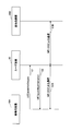
- FIG. 1 is a diagram showing a configuration example of a network architecture according to an embodiment of the present invention.
- the wireless network architecture according to the embodiment of the present invention includes 4G-CU, 4G-RU (RemoteUnit, remote radio station), EPC (EvolvedPacketCore), etc. on the LTE-Advanced side.
- the wireless network architecture in the embodiment of the present invention includes 5G-CU, 5G-DU and the like on the 5G side.
- 4G-CU includes RRC (RadioResourceControl), PDCP (PacketDataConvergenceProtocol), RLC (RadioLinkControl), MAC (MediumAccessControl), L1 (Layer 1, PHY layer or It includes layers up to the physical layer) and is connected to 4G-RU via CPRI (Common Public Radio Interface).
- RRC RadioResourceControl
- PDCP PacketDataConvergenceProtocol
- RLC RadioLinkControl
- MAC MediumAccessControl
- L1 Layer 1, PHY layer or It includes layers up to the physical layer
- CPRI Common Public Radio Interface
- the 5G-CU includes an RRC layer, is connected to the 5G-DU via an FH (Flonthaul) interface, and has a 5GC (5G Core Network) and an NG interface (NG). It is connected via interface). Further, the 5G-CU is connected to the 4G-CU by an X2 interface.
- the PDCP layer in 4G-CU serves as a coupling or separation point when performing DC (Dual Connectivity) of 4G-5G, that is, EN-DC (E-UTRA-NR Dual Connectivity).
- a network node including 5G-CU and 5G-DU is called gNB.
- 5G-CU may be referred to as gNB-CU
- 5G-DU may be referred to as gNB-DU.
- CA Carrier Aggregation
- DC is performed between 4G-RU and 5G-DU.
- a UE User Equipment
- a UE User Equipment
- FIG. 1 shows the wireless network architecture at the time of LTE-NR DC, that is, EN-DC (E-UTRA-NR Dual Connectivity).
- EN-DC E-UTRA-NR Dual Connectivity
- a similar wireless network architecture may be used when separating 4G-CU into CU-DU or when operating NR standalone.
- the functions related to the RRC layer and the PDCP layer may be transferred to the 4G-CU, and the RLC layer and below may be included in the 4G-DU.
- the CU-DU separation may reduce the CPRI data rate.
- a plurality of 5G-DUs may be connected to the 5G-CU.
- NR-DC NR-NR Dual Connectivity
- the 5G-CU may be directly connected to the EPC without going through the 4G-CU, or the 4G-CU may be directly connected to the 5GC without going through the 5G-CU.
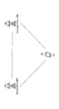
- FIG. 2 is a diagram showing a configuration example of a wireless communication system according to an embodiment of the present invention.
- FIG. 2 is a schematic view showing a wireless communication system at the time of MR-DC (Multi-RAT Dual Connectivity).
- MR-DC Multi-RAT Dual Connectivity
- the user apparatus 20 does not distinguish between the base station apparatus 10A provided by the NR system and the base station apparatus 10B provided by the NR system (hereinafter, the base station apparatus 10A and the base station apparatus 10B are not distinguished). It may be referred to as "base station device 10"). Further, the user device 20 has NR-NR dual connectivity in which the base station device 10A is a master node (hereinafter, also referred to as “MN”) and the base station device 10B is a secondary node (hereinafter, also referred to as “SN”). That is, it supports NR-DC.
- MN master node
- SN secondary node
- the user device 20 simultaneously uses a plurality of component carriers provided by the base station device 10A which is the master node and the base station device 10B which is the secondary node, and the base station device 10A which is the master node and the base which is the secondary node. It is possible to execute simultaneous transmission or simultaneous reception with the station device 10B.
- the user apparatus 20 may communicate with the base station apparatus 10A provided by the LTE system and the base station apparatus 10B provided by the NR system. Further, the user apparatus 20 may support LTE-NR dual connectivity, that is, EN-DC, in which the base station apparatus 10A is an MN and the base station apparatus 10B is an SN.
- the user device 20 simultaneously uses a plurality of component carriers provided by the base station device 10A which is the master node and the base station device 10B which is the secondary node, and the base station device 10A which is the master node and the base which is the secondary node. It is possible to execute simultaneous transmission or simultaneous reception with the station device 10B.
- the user apparatus 20 may communicate with the base station apparatus 10A provided by the NR system and the base station apparatus 10B provided by the LTE system. Further, the user apparatus 20 may support NR-LTE dual connectivity in which the base station apparatus 10A is an MN and the base station apparatus 10B is an SN, that is, NE-DC (NR-E-UTRA Dual Connectivity).
- the user device 20 simultaneously uses a plurality of component carriers provided by the base station device 10A which is the master node and the base station device 10B which is the secondary node, and the base station device 10A which is the master node and the base which is the secondary node. It is possible to execute simultaneous transmission or simultaneous reception with the station device 10B.
- the user device 20 may communicate with the base station device 10A provided by the NR system and the base station device 10B provided by the NR system. Further, the user apparatus 20 may support NR-NR dual connectivity, that is, NR-DC, in which the base station apparatus 10A is an MN and the base station apparatus 10B is an SN.
- the user device 20 simultaneously uses a plurality of component carriers provided by the base station device 10A which is the master node and the base station device 10B which is the secondary node, and the base station device 10A which is the master node and the base which is the secondary node. It is possible to execute simultaneous transmission or simultaneous reception with the station device 10B.
- the user device 20 is not limited to the above dual connectivity, and may have different RATs. It is applicable to dual connectivity between multiple wireless communication systems used, that is, MR-DC.
- the parameters and elements related to the capability of the user device 20 are not defined in common to all CCs (Component Carriers), but are defined for each band combination, each band of the band combination, or each CC of the band combination. Therefore, even in the same band combination, the parameters and elements related to the capability of the user device 20 for CA and the parameters and elements related to the capability of the user device 20 for DC are set separately.
- CCs Component Carriers
- the capability of the user device 20 related to "band 1 + band 2" for CA and “band 1 + band 2" for DC It is necessary to signal the capability of the user apparatus 20 and the signaling size is increased.
- ca-Paramators NR for NR-DC and the featureSetCombination for NR-DC it is possible to signal the ca-Paramators NR for NR-DC and the featureSetCombination for NR-DC. To do. Further, when the ca-Parameters NR for NR-DC and the faceureSetCombination for NR-DC are not signaled, the ca-ParametersNR for CA and the featureSetCombination for CA can be used for NR-DC. Both ca-Parameters NR and featureSetCombination are UE capabilities defined for each band combination.
- the ca-parameters NR supports simultaneous transmission of PRACH, SRS (Sounding Reference Signal), PUCCH (Physical Uplink Control Channel) and PUSCH (Physical Uplink Shared Channel), for example, whether or not to support multiple TAs (Timing Advance). It includes parameters indicating whether or not to support simultaneous transmission / reception in the inter-band CA or SUL. That is, the ca-Paramators NR includes the setting parameters related to the CA defined for each band combination.
- the featureSetCombination is a two-dimensional matrix of featureSet entries, and the featureSet includes downlink and uplink configuration parameters. For example, information indicating the scaling factor, whether or not cross-carrier scheduling is supported, the subcarrier interval, the bandwidth, and the like are included in the featureSet. That is, the featureSetCombination includes downlink and uplink setting parameters defined for each band combination.
- FIG. 3 is a sequence diagram for explaining an operation example according to the embodiment of the present invention.
- the base station apparatus 10A which is the master node, transmits an RRC message “UECapacityEnquiry” to the user apparatus 20.
- the “UECapacityEnquiry” is used for the base station apparatus 10A to acquire the UE capability of the user apparatus 20.
- the user apparatus 20 transmits “UECapacity Information” to the base station apparatus 10A (S2).
- the "UE Capacity Information” is used to transmit the UE capability of the user apparatus 20 to the base station apparatus 10A.
- the "UE Capability Information” includes the above-mentioned CA band combination as a UE capability, and includes, for example, "BandCombinationList", "BandCombinationList-v15xy” and the like.
- step S3A the base station apparatus 10A executes communication with the user apparatus 20 by using the band combination of NR-DC supported by the user apparatus 20 notified by the "UECapacity Information”.
- the base station apparatus 10B performs communication with the user apparatus 20 by using the band combination of NR-DC supported by the user apparatus 20 notified by the "UECapacity Information”.
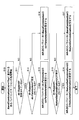
- FIG. 4 is a flowchart for explaining an operation example according to the embodiment of the present invention.
- the flowchart may be applied when the user device 20 sets the "BandCombinationList" included in the "UECapacity Information", or the information when the base station device 10 receives the "BandCombinationList” included in the "UECapacity Information”. It may be applied to the interpretation of the element.
- step S10 the processing of one band combination included in "BandCombinationList-v15xy", which is one of the CA band combinations, is started.
- step S11 the base station apparatus 10 determines whether or not the information element "dc-Support" is set in the "BandCombinationList-v15xy". If “dc-Support” is set (YES in S11), the process proceeds to step S12, and if "dc-Support" is not set (NO in S11), the band combination must support NR-DC. Judge and end the flow.
- step S11 when the user device 20 sets the "BandCombinationList" included in the "UECapacity Information", if the band combination supports DC, "dc-Support” is set and the band combination does not support DC. If “dc-Support” is not set.
- step S12 the base station apparatus 10 determines whether or not the information element "dc-parameters" is set in the "dc-Support". If “dc-parameters" is set (YES in S12), the process proceeds to step S13, and if "dc-parameters” is not set (NO in S12), the process proceeds to step S14.
- step S12 when the user device 20 sets "dc-Paramators" included in "dc-Support", when the NR-DC parameter is set separately from CA in the band combination, “dc-Parameters”. If the NR-DC parameter is not set separately from CA for the band combination, “dc-Paramators" is not set.
- step S13 the base station apparatus 10 sets the information element "ca-ParameterNR” of "dc-Parameters” in the NR-DC parameter of the band combination.
- step S14 the base station apparatus 10 sets the information element “ca-Parameter NR” of “BandCombination” in the NR-DC parameter of the band combination.
- the "BandCombination” is an information element included in the "BandCombinationList", and is transmitted from the user device 20 to the base station device 10 by the "UECapacity Information".
- step S15 the base station apparatus 10 determines whether or not the information element "featureSetCombinationDC" is set in the "dc-Support". If “fairureSetCombinationDC” is set (YES in S15), the process proceeds to step S16, and if “fairureSetCombinationDC” is not set (NO in S15), the process proceeds to step S17.
- step S15 when the user device 20 sets the "featureSetCombinationDC” included in the "dc-Support", when the NR-DC parameter is set separately from the CA in the band combination, the “featureSetCombinationDC” is set. If the NR-DC parameter is not set separately from CA for the band combination, "featureSetCombinationDC” is not set.
- step S16 the base station apparatus 10 sets the information element "featureSetCombination” indicated by “fairtureSetCombinationDC” in the NR-DC parameter of the band combination, and ends the bath.
- step S17 the base station apparatus 10 sets the information element “featureSetCombination” indicated by “BandCombination” in the NR-DC parameter of the band combination, and ends the flow.
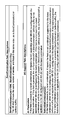
- FIG. 5 is a diagram showing an example (1) of specification change in the embodiment of the present invention.
- the information element "BandCombinationList-v15xy” includes a maximum of maxBandComb information elements "BandCombinationList-v15xy”.
- “BandCombinationList-v15xy” includes an information element "dc-Support”.
- “Dc-Support” includes the information element “DC-Support”.
- DC-Support” includes an information element “dc-Parameters” and an information element “featureSetCombinationDC”.
- the "dc-parameters” includes the information element "CA-parameters NR”.
- the "fairureSetCombinationDC” includes the information element "FatureSetCombinationId”.
- “CA-ParametersNR” includes the UE capability associated with the CA defined for each band combination.
- “FatureSetCombinationId” is an identifier that identifies theFatureSetCombination.
- FIG. 6 is a diagram showing an example (2) of specification change in the embodiment of the present invention. As shown in FIG. 6, "BandCombinationList-v15xy" includes the same number of entries as “BandCombinationList” in the same order.
- dc-Parameters when “dc-Parameters” is included in “DC-Support”, “dc-Parameters” is the band combination when NR-DC is set as the target band combination. Indicates the UE capability related to. That is, “dc-Paramators” includes setting parameters related to CA defined for each band combination. When “dc-Parameters" is not included in “DC-Support”, when NR-DC is set for the target band combination, UE capability by "BandCombination" is set for the band combination.
- “fairureSetCombinationDC” when “fairureSetCombinationDC” is included in “DC-Support”, “fairtureSetCombinationDC” indicates a facialSet when NR-DC is set for the target band combination. That is, the “featureSetCombinationDC” includes downlink and uplink setting parameters defined for each band combination.
- “featureSetCombinationDC” when “featureSetCombinationDC” is not included in “DC-Support”, when NR-DC is set for the target band combination, the "fairtureSet” by "BandCombination” is set for the band combination.
- the user apparatus 20 when the user apparatus 20 is set to NR-DC in a certain band combination and supports the same UE capability as CA in the band combination by the NR-DC in the band combination, NR- By not including the UE capability for DC in the report, the UE capability report with a reduced amount of data can be transmitted to the base station apparatus 10. Further, when NR-DC is set for a certain band combination and the UE capability different from CA in the band combination is supported by the NR-DC in the band combination, the user device 20 has a UE capability for NR-DC. Is included in the report, so that a UE capability report corresponding to NR-DC in which a UE capability different from CA is supported can be transmitted to the base station apparatus 10.
- the base station apparatus 10 and the user apparatus 20 include a function of carrying out the above-described embodiment.
- the base station apparatus 10 and the user apparatus 20 may each have only a part of the functions in the embodiment.
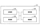
- FIG. 7 is a diagram showing an example of the functional configuration of the base station device 10 according to the embodiment of the present invention.
- the base station apparatus 10 includes a transmission unit 110, a reception unit 120, a setting unit 130, and a control unit 140.
- the functional configuration shown in FIG. 7 is only an example. Any function classification and name of the functional unit may be used as long as the operation according to the embodiment of the present invention can be executed.
- the transmission unit 110 includes a function of generating a signal to be transmitted to the user device 20 side and transmitting the signal wirelessly. Further, the transmission unit 110 transmits a message between network nodes to another network node.
- the receiving unit 120 includes a function of receiving various signals transmitted from the user apparatus 20 and acquiring information of, for example, a higher layer from the received signals. Further, the transmission unit 110 has a function of transmitting NR-PSS, NR-SSS, NR-PBCH, DL / UL control signals, and the like to the user device 20. In addition, the receiving unit 120 receives a message between network nodes from another network node.
- the setting unit 130 stores preset setting information and various setting information to be transmitted to the user device 20.
- the contents of the setting information are, for example, setting information related to dual connectivity, information related to transmission / reception setting according to the UE capability of the user device 20, and the like.
- control unit 140 performs control related to transmission / reception including dual connectivity with the user device 20 and control related to processing of the UE capability report received from the user device 20.
- the function unit related to signal transmission in the control unit 140 may be included in the transmission unit 110, and the function unit related to signal reception in the control unit 140 may be included in the reception unit 120.
- FIG. 8 is a diagram showing an example of the functional configuration of the user device 20 according to the embodiment of the present invention.
- the user device 20 includes a transmission unit 210, a reception unit 220, a setting unit 230, and a control unit 240.
- the functional configuration shown in FIG. 8 is only an example. Any function classification and name of the functional unit may be used as long as the operation according to the embodiment of the present invention can be executed.
- the transmission unit 210 creates a transmission signal from the transmission data and wirelessly transmits the transmission signal.
- the receiving unit 220 wirelessly receives various signals and acquires a signal of a higher layer from the received signal of the physical layer. Further, the receiving unit 220 has a function of receiving NR-PSS, NR-SSS, NR-PBCH, DL / UL / SL control signals and the like transmitted from the base station apparatus 10. Further, for example, the transmission unit 210 connects the other user device 20 to the PSCCH (Physical Sidelink Control Channel), PSCH (Physical Sidelink Shared Channel), PSDCH (Physical Sidelink Discovery Channel), PSBCH (Physical Sidelink Broadcast Channel) as D2D communication. ) Etc., and the receiving unit 120 receives the PSCCH, PSCH, PSDCH, PSBCH, etc. from the other user device 20.
- PSCCH Physical Sidelink Control Channel
- PSCH Physical Sidelink Shared Channel
- PSDCH Physical Sidelink Discovery Channel
- PSBCH
- the setting unit 230 stores various setting information received from the base station device 10 by the receiving unit 220.
- the setting unit 230 also stores preset setting information.
- the contents of the setting information are, for example, setting information related to dual connectivity, information related to transmission / reception setting according to UE capability, and the like.
- control unit 240 performs control related to the UE capability report of the user device 20 and transmission / reception control including dual connectivity according to the UE capability.
- the function unit related to signal transmission in the control unit 240 may be included in the transmission unit 210, and the function unit related to signal reception in the control unit 240 may be included in the reception unit 220.
- each functional block may be realized by using one device that is physically or logically connected, or directly or indirectly (for example, by two or more devices that are physically or logically separated). , Wired, wireless, etc.) and may be realized using these plurality of devices.
- the functional block may be realized by combining the software with the one device or the plurality of devices.
- Functions include judgment, decision, judgment, calculation, calculation, processing, derivation, investigation, search, confirmation, reception, transmission, output, access, solution, selection, selection, establishment, comparison, assumption, expectation, and assumption.
- broadcasting notifying, communicating, forwarding, configuring, reconfiguring, allocating, mapping, assigning, etc., but only these. I can't.
- a functional block (constituent unit) that functions transmission is called a transmitting unit or a transmitter.
- the method of realizing each of them is not particularly limited.
- the base station device 10, the user device 20, and the like in one embodiment of the present disclosure may function as a computer that processes the wireless communication method of the present disclosure.
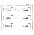
- FIG. 9 is a diagram showing an example of the hardware configuration of the base station device 10 and the user device 20 according to the embodiment of the present disclosure.
- the above-mentioned base station device 10 and user device 20 are physically configured as a computer device including a processor 1001, a storage device 1002, an auxiliary storage device 1003, a communication device 1004, an input device 1005, an output device 1006, a bus 1007, and the like. May be done.
- the word “device” can be read as a circuit, device, unit, etc.
- the hardware configuration of the base station device 10 and the user device 20 may be configured to include one or more of the devices shown in the figure, or may be configured not to include some of the devices.
- the processor 1001 For each function in the base station device 10 and the user device 20, by loading predetermined software (program) on the hardware such as the processor 1001 and the storage device 1002, the processor 1001 performs an calculation and the communication device 1004 performs communication. It is realized by controlling or controlling at least one of reading and writing of data in the storage device 1002 and the auxiliary storage device 1003.
- the processor 1001 operates, for example, an operating system to control the entire computer.
- the processor 1001 may be composed of a central processing unit (CPU: Central Processing Unit) including an interface with a peripheral device, a control device, an arithmetic unit, a register, and the like.
- CPU Central Processing Unit
- control unit 140, control unit 240, and the like may be realized by the processor 1001.
- the processor 1001 reads a program (program code), a software module, data, or the like from at least one of the auxiliary storage device 1003 and the communication device 1004 into the storage device 1002, and executes various processes according to these.
- a program that causes a computer to execute at least a part of the operations described in the above-described embodiment is used.
- the control unit 140 of the base station device 10 shown in FIG. 7 may be realized by a control program stored in the storage device 1002 and operated by the processor 1001.
- the control unit 240 of the user device 20 shown in FIG. 8 may be realized by a control program stored in the storage device 1002 and operated by the processor 1001.
- Processor 1001 may be implemented by one or more chips.
- the program may be transmitted from the network via a telecommunication line.
- the storage device 1002 is a computer-readable recording medium, for example, by at least one of ROM (Read Only Memory), EPROM (Erasable Programmable ROM), EPROM (Electrically Erasable Programmable ROM), RAM (Random Access Memory), and the like. It may be configured.
- the storage device 1002 may be referred to as a register, a cache, a main memory (main storage device), or the like.
- the storage device 1002 can store a program (program code), a software module, or the like that can be executed to implement the communication method according to the embodiment of the present disclosure.
- the auxiliary storage device 1003 is a computer-readable recording medium, for example, an optical disk such as a CD-ROM (Compact Disc ROM), a hard disk drive, a flexible disk, a magneto-optical disk (for example, a compact disk, a digital versatile disk, Blu).
- -It may be composed of at least one of a ray (registered trademark) disk), a smart card, a flash memory (for example, a card, a stick, a key drive), a floppy (registered trademark) disk, a magnetic strip, and the like.
- the storage medium described above may be, for example, a database, server or other suitable medium containing at least one of the storage device 1002 and the auxiliary storage device 1003.
- the communication device 1004 is hardware (transmission / reception device) for communicating between computers via at least one of a wired network and a wireless network, and is also referred to as, for example, a network device, a network controller, a network card, a communication module, or the like.
- the communication device 1004 includes, for example, a high frequency switch, a duplexer, a filter, a frequency synthesizer, and the like in order to realize at least one of frequency division duplex (FDD: Frequency Division Duplex) and time division duplex (TDD: Time Division Duplex). It may be composed of.
- FDD Frequency Division Duplex
- TDD Time Division Duplex
- the transmission / reception unit may be physically or logically separated from each other in the transmission unit and the reception unit.
- the input device 1005 is an input device (for example, a keyboard, a mouse, a microphone, a switch, a button, a sensor, etc.) that receives an input from the outside.
- the output device 1006 is an output device (for example, a display, a speaker, an LED lamp, etc.) that outputs to the outside.
- the input device 1005 and the output device 1006 may have an integrated configuration (for example, a touch panel).
- each device such as the processor 1001 and the storage device 1002 is connected by a bus 1007 for communicating information.
- the bus 1007 may be configured by using a single bus, or may be configured by using a different bus for each device.
- the base station device 10 and the user device 20 include a microprocessor, a digital signal processor (DSP: Digital Signal Processor), an ASIC (Application Specific Integrated Circuit), a PLD (Programmable Logic Device), an FPGA (Field Programmable Gate Array), and the like. It may be configured to include hardware, and the hardware may realize a part or all of each functional block. For example, processor 1001 may be implemented using at least one of these hardware.
- DSP Digital Signal Processor
- ASIC Application Specific Integrated Circuit
- PLD Programmable Logic Device
- FPGA Field Programmable Gate Array
- the receiver that receives the information requesting the report of the UE (User Equipment) capability from the base station apparatus and the UE capability supported in the band combination are described above. It has a control unit to be included in the report and a transmission unit to transmit the report to the base station apparatus, and the control unit indicates that the parameters supported by carrier aggregation are applied to the dual connectivity in the band combination.
- a user device is provided that includes the information shown in the report.
- the user apparatus 20 when NR-DC is set for a certain band combination and the same UE capability as CA in the band combination is supported by NR-DC in the band combination, the user apparatus 20 is NR-DC.
- the UE capability report with a reduced amount of data can be transmitted to the base station apparatus 10. That is, it is possible to improve the efficiency of reporting the capabilities of the user equipment in the dual connectivity performed in the wireless communication system.
- the control unit applies the parameters supported in the band combination that performs carrier aggregation with the base station device in the band combination to the dual connectivity, and when the control unit performs dual connectivity with the base station device in the band combination. It is not necessary to set the first information element in the report and set the second information element in the first information element.
- the user device 20 is for NR-DC when NR-DC is set for a certain band combination and when the same UE capability as CA in the band combination is supported by NR-DC in the band combination. By not including the UE capability of the above in the report, the UE capability report with a reduced amount of data can be transmitted to the base station apparatus 10.
- the second information element may be a setting parameter related to carrier aggregation defined for each band combination or a downlink and uplink setting parameter defined for each band combination.
- a transmitter that transmits information requesting a report of UE (User Equipment) capability to a user device, a receiver that receives the report from the user device, and the report. It has a control unit that sets the communication to which dual connectivity is applied based on the UE capability supported in the band combination included, and the control unit has dual parameters supported by carrier aggregation in the band combination. If the report contains information indicating that it applies to connectivity, a base station apparatus is provided that applies the parameters supported by carrier aggregation to dual connectivity in the band combination.
- UE User Equipment
- the user apparatus 20 is NR-DC when NR-DC is set for a certain band combination and when the same UE capability as CA in the band combination is supported by NR-DC in the band combination.
- the UE capability report with a reduced amount of data can be transmitted to the base station apparatus 10. That is, it is possible to improve the efficiency of reporting on the capabilities of the user equipment in dual connectivity performed in a wireless communication system.
- the operation of the plurality of functional units may be physically performed by one component, or the operation of one functional unit may be physically performed by a plurality of components.
- the order of processing may be changed as long as there is no contradiction.
- the base station apparatus 10 and the user apparatus 20 have been described with reference to functional block diagrams, but such devices may be implemented in hardware, software, or a combination thereof.
- the software operated by the processor of the base station apparatus 10 according to the embodiment of the present invention and the software operated by the processor of the user apparatus 20 according to the embodiment of the present invention are random access memory (RAM), flash memory, and read, respectively. It may be stored in a dedicated memory (ROM), EPROM, EEPROM, registers, hard disk (HDD), removable disk, CD-ROM, database, server or any other suitable storage medium.
- information notification includes physical layer signaling (for example, DCI (Downlink Control Information), UCI (Uplink Control Information)), higher layer signaling (for example, RRC (Radio Resource Control) signaling, MAC (Medium Access Control) signaling, etc. Broadcast information (MIB (Master Information Block), SIB (System Information Block)), other signals, or a combination thereof may be used.
- RRC signaling may be referred to as an RRC message, for example, RRC. It may be a connection setup (RRCConnectionSetup) message, an RRC connection reconfiguration (RRCConnectionReconfiguration) message, or the like.
- Each aspect / embodiment described in the present disclosure includes LTE (Long Term Evolution), LTE-A (LTE-Advanced), SUPER 3G, IMT-Advanced, 4G (4th generation mobile communication system), and 5G (5th generation mobile communication).
- system FRA (Future Radio Access), NR (new Radio), W-CDMA (registered trademark), GSM (registered trademark), CDMA2000, UMB (Ultra Mobile Broadband), IEEE 802.11 (Wi-Fi (registered trademark)) )), LTE 802.16 (WiMAX®), IEEE 802.20, UWB (Ultra-WideBand), Bluetooth®, and other systems that utilize suitable systems and have been extended based on these. It may be applied to at least one of the next generation systems. Further, a plurality of systems may be applied in combination (for example, a combination of at least one of LTE and LTE-A and 5G).
- the specific operation performed by the base station apparatus 10 in the present specification may be performed by its upper node (upper node).
- various operations performed for communication with the user device 20 are other than the base station device 10 and the base station device 10. It is clear that this can be done by at least one of the network nodes (eg, MME or S-GW, etc., but not limited to these).
- the network nodes eg, MME or S-GW, etc., but not limited to these.
- the other network nodes may be a combination of a plurality of other network nodes (for example, MME and S-GW). Good.
- the information, signals, etc. described in the present disclosure can be output from the upper layer (or lower layer) to the lower layer (or upper layer). Input / output may be performed via a plurality of network nodes.
- the input / output information and the like may be saved in a specific location (for example, memory), or may be managed using a management table. Input / output information and the like can be overwritten, updated, or added. The output information and the like may be deleted. The input information or the like may be transmitted to another device.
- the determination in the present disclosure may be made by a value represented by 1 bit (0 or 1), by a true / false value (Boolean: true or false), or by comparing numerical values (for example). , Comparison with a predetermined value).
- Software is an instruction, instruction set, code, code segment, program code, program, subprogram, software module, whether called software, firmware, middleware, microcode, hardware description language, or another name.
- Applications, software applications, software packages, routines, subroutines, objects, executable files, execution threads, procedures, functions, etc. should be broadly interpreted to mean.
- software, instructions, information, etc. may be transmitted and received via a transmission medium.
- a transmission medium For example, a website that uses at least one of wired technology (coaxial cable, fiber optic cable, twist pair, digital subscriber line (DSL: Digital Subscriber Line), etc.) and wireless technology (infrared, microwave, etc.) When transmitted from a server, or other remote source, at least one of these wired and wireless technologies is included within the definition of transmission medium.
- data, instructions, commands, information, signals, bits, symbols, chips, etc. may be voltage, current, electromagnetic waves, magnetic fields or magnetic particles, light fields or photons, or any of these. It may be represented by a combination of.
- a channel and a symbol may be a signal (signaling).
- the signal may be a message.
- the component carrier CC: Component Carrier
- CC Component Carrier
- system and “network” used in this disclosure are used interchangeably.
- the information, parameters, etc. described in the present disclosure may be expressed using absolute values, relative values from predetermined values, or using other corresponding information. It may be represented.
- the radio resource may be one indicated by an index.
- base station Base Station
- wireless base station base station
- base station device fixed station
- NodeB nodeB
- eNodeB eNodeB
- GNB nodeB
- access point “ transmission point (transmission point) ”,“ reception point ”,“ transmission / reception point (transmission / reception point) ”,“ cell ”,“ sector ”,
- Terms such as “cell group,” “carrier,” and “component carrier” can be used interchangeably.
- Base stations are sometimes referred to by terms such as macrocells, small cells, femtocells, and picocells.
- the base station can accommodate one or more (for example, three) cells.
- a base station accommodates multiple cells, the entire coverage area of the base station can be divided into multiple smaller areas, each smaller area being a base station subsystem (eg, a small indoor base station (RRH:)).
- Communication services can also be provided by (Remote Radio Head).
- the term "cell” or “sector” is a part or all of the coverage area of at least one of the base station and the base station subsystem that provides the communication service in this coverage. Point to.
- MS Mobile Station
- UE User Equipment
- Mobile stations can be subscriber stations, mobile units, subscriber units, wireless units, remote units, mobile devices, wireless devices, wireless communication devices, remote devices, mobile subscriber stations, access terminals, mobile terminals, wireless, depending on the trader. It may also be referred to as a terminal, remote terminal, handset, user agent, mobile client, client, or some other suitable term.
- At least one of the base station and the mobile station may be called a transmitting device, a receiving device, a communication device, or the like.
- At least one of the base station and the mobile station may be a device mounted on the mobile body, the mobile body itself, or the like.
- the moving body may be a vehicle (eg, car, airplane, etc.), an unmanned moving body (eg, drone, self-driving car, etc.), or a robot (manned or unmanned). ) May be.
- at least one of the base station and the mobile station includes a device that does not necessarily move during communication operation.
- at least one of the base station and the mobile station may be an IoT (Internet of Things) device such as a sensor.
- IoT Internet of Things
- the base station in the present disclosure may be read by the user terminal.
- the communication between the base station and the user terminal is replaced with the communication between a plurality of user devices 20 (for example, it may be called D2D (Device-to-Device), V2X (Vehicle-to-Everything), etc.).
- D2D Device-to-Device
- V2X Vehicle-to-Everything
- Each aspect / embodiment of the present disclosure may be applied to the configuration.
- the user device 20 may have the functions of the base station device 10 described above.
- words such as "up” and “down” may be read as words corresponding to inter-terminal communication (for example, "side").
- the uplink, downlink, and the like may be read as side channels.
- the user terminal in the present disclosure may be read as a base station.
- the base station may have the functions of the user terminal described above.
- determining and “determining” used in this disclosure may include a wide variety of actions.
- “Judgment” and “decision” are, for example, judgment (judging), calculation (calculating), calculation (computing), processing (processing), derivation (deriving), investigation (investigating), search (looking up, search, inquiry). It may include (eg, searching in a table, database or another data structure), ascertaining as “judgment” or “decision”.
- judgment and “decision” are receiving (for example, receiving information), transmitting (for example, transmitting information), input (input), output (output), and access. (Accessing) (for example, accessing data in memory) may be regarded as “judgment” or “decision”.
- judgment and “decision” mean that “resolving”, “selecting”, “choosing”, “establishing”, “comparing”, etc. are regarded as “judgment” and “decision”. Can include. That is, “judgment” and “decision” may include that some action is regarded as “judgment” and “decision”. Further, “judgment (decision)” may be read as “assuming”, “expecting”, “considering” and the like.
- connection means any direct or indirect connection or connection between two or more elements, and each other. It can include the presence of one or more intermediate elements between two “connected” or “combined” elements.
- the connection or connection between the elements may be physical, logical, or a combination thereof.
- connection may be read as "access”.
- the two elements use at least one of one or more wires, cables and printed electrical connections, and, as some non-limiting and non-comprehensive examples, the radio frequency domain. Can be considered to be “connected” or “coupled” to each other using electromagnetic energies having wavelengths in the microwave and light (both visible and invisible) regions.
- the reference signal can also be abbreviated as RS (Reference Signal), and may be called a pilot (Pilot) depending on the applicable standard.
- RS Reference Signal
- Pilot Pilot
- references to elements using designations such as “first”, “second”, etc. as used in this disclosure does not generally limit the quantity or order of those elements. These designations can be used in the present disclosure as a convenient way to distinguish between two or more elements. Thus, references to the first and second elements do not mean that only two elements can be adopted, or that the first element must somehow precede the second element.
- the wireless frame may be composed of one or more frames in the time domain. Each one or more frames in the time domain may be referred to as a subframe. Subframes may further consist of one or more slots in the time domain.
- the subframe may have a fixed time length (eg, 1 ms) that is independent of numerology.
- the numerology may be a communication parameter that applies to at least one of the transmission and reception of a signal or channel.
- Numerology includes, for example, subcarrier spacing (SCS: SubCarrier Spacing), bandwidth, symbol length, cyclic prefix length, transmission time interval (TTI: Transmission Time Interval), number of symbols per TTI, wireless frame configuration, transmitter / receiver.
- SCS subcarrier spacing
- TTI Transmission Time Interval
- At least one of a specific filtering process performed in the frequency domain, a specific windowing process performed by the transmitter / receiver in the time domain, and the like may be indicated.
- the slot may be composed of one or more symbols (OFDM (Orthogonal Frequency Division Multiplexing) symbols, SC-FDMA (Single Carrier Frequency Division Multiple Access) symbols, etc.) in the time domain. Slots may be time units based on new melody.
- OFDM Orthogonal Frequency Division Multiplexing
- SC-FDMA Single Carrier Frequency Division Multiple Access
- the slot may include a plurality of mini slots. Each minislot may consist of one or more symbols in the time domain. Further, the mini slot may be called a sub slot. A minislot may consist of a smaller number of symbols than the slot.
- a PDSCH (or PUSCH) transmitted in time units larger than the minislot may be referred to as a PDSCH (or PUSCH) mapping type A.
- the PDSCH (or PUSCH) transmitted using the minislot may be referred to as PDSCH (or PUSCH) mapping type B.
- the wireless frame, subframe, slot, minislot and symbol all represent the time unit when transmitting a signal.
- the radio frame, subframe, slot, minislot and symbol may have different names corresponding to each.
- one subframe may be called a transmission time interval (TTI), a plurality of consecutive subframes may be called TTI, and one slot or one minislot may be called TTI.
- TTI transmission time interval
- the unit representing TTI may be called a slot, a mini slot, or the like instead of a subframe.
- TTI refers to, for example, the minimum time unit of scheduling in wireless communication.
- the base station schedules each user device 20 to allocate radio resources (frequency bandwidth that can be used in each user device 20, transmission power, etc.) in TTI units.
- the definition of TTI is not limited to this.
- the TTI may be a transmission time unit such as a channel-encoded data packet (transport block), a code block, or a code word, or may be a processing unit such as scheduling or link adaptation.
- the time interval for example, the number of symbols
- the transport block, code block, code word, etc. may be shorter than the TTI.
- one or more TTIs may be the minimum time unit for scheduling. Further, the number of slots (number of mini-slots) constituting the minimum time unit of the scheduling may be controlled.
- a TTI having a time length of 1 ms may be referred to as a normal TTI (TTI in LTE Rel. 8-12), a normal TTI, a long TTI, a normal subframe, a normal subframe, a long subframe, a slot, or the like.
- TTIs shorter than normal TTIs may be referred to as shortened TTIs, short TTIs, partial TTIs (partial or fractional TTIs), shortened subframes, short subframes, minislots, subslots, slots, and the like.
- the long TTI (for example, normal TTI, subframe, etc.) may be read as a TTI having a time length of more than 1 ms, and the short TTI (for example, shortened TTI, etc.) is less than the TTI length of the long TTI and 1 ms. It may be read as a TTI having the above TTI length.
- the resource block (RB) is a resource allocation unit in the time domain and the frequency domain, and may include one or a plurality of continuous subcarriers in the frequency domain.
- the number of subcarriers contained in the RB may be the same regardless of the numerology, and may be, for example, 12.
- the number of subcarriers contained in the RB may be determined based on numerology.
- the time domain of RB may include one or more symbols, and may have a length of 1 slot, 1 mini slot, 1 subframe, or 1 TTI.
- Each 1TTI, 1 subframe, etc. may be composed of one or a plurality of resource blocks.
- one or more RBs include a physical resource block (PRB: Physical RB), a sub-carrier group (SCG: Sub-Carrier Group), a resource element group (REG: Resource Element Group), a PRB pair, an RB pair, and the like. May be called.
- PRB Physical resource block
- SCG Sub-Carrier Group
- REG Resource Element Group
- PRB pair an RB pair, and the like. May be called.
- the resource block may be composed of one or a plurality of resource elements (RE: Resource Element).
- RE Resource Element
- 1RE may be a radio resource area of 1 subcarrier and 1 symbol.
- Bandwidth part (which may also be called partial bandwidth) may represent a subset of consecutive common resource blocks (RBs) for a certain neurology in a carrier.
- the common RB may be specified by the index of the RB with respect to the common reference point of the carrier.
- PRBs may be defined in a BWP and numbered within that BWP.
- the BWP may include a BWP for UL (UL BWP) and a BWP for DL (DL BWP).
- UL BWP UL BWP
- DL BWP DL BWP
- One or more BWPs may be set in one carrier for the UE.
- At least one of the configured BWPs may be active, and the UE may not expect to send or receive a given signal / channel outside the active BWP.
- “cell”, “carrier” and the like in this disclosure may be read as “BWP”.
- the above-mentioned structures such as wireless frames, subframes, slots, mini slots and symbols are merely examples.
- the number of subframes contained in a wireless frame the number of slots per subframe or wireless frame, the number of minislots contained within a slot, the number of symbols and RBs contained in a slot or minislot, included in the RB.
- the number of subcarriers, the number of symbols in the TTI, the symbol length, the cyclic prefix (CP: Cyclic Prefix) length, and other configurations can be changed in various ways.
- the term "A and B are different” may mean “A and B are different from each other”.
- the term may mean that "A and B are different from C”.
- Terms such as “separate” and “combined” may be interpreted in the same way as “different”.
- the notification of predetermined information (for example, the notification of "being X") is not limited to the explicit one, but is performed implicitly (for example, the notification of the predetermined information is not performed). May be good.
- UECapacityEnquiry is an example of information requesting reporting of UE capability.
- UECapacity Information is an example of reporting UE capability.
- the transmitting unit 210 and the receiving unit 220 are examples of communication units.
- BandCombination's ca-ParamatorsNR or featureSetCombination is an example of the parameters supported in a band combination that performs carrier aggregation.
- dc-Support is an example of a first information element.
- the dc-parameters or featureSetCombinationDC is an example of a second information element.
- dc-Parameters is an example of setting parameters related to carrier aggregation defined for each band combination.
- the featureSetCombinationDC is an example of downlink and uplink setting parameters defined for each band combination.
- Base station device 110 Transmission unit 120 Reception unit 130 Setting unit 140 Control unit 20 User device 210 Transmission unit 220 Reception unit 230 Setting unit 240 Control unit 1001 Processor 1002 Storage device 1003 Auxiliary storage device 1004 Communication device 1005 Input device 1006 Output device
Abstract
Un dispositif utilisateur comprend : une unité de réception qui reçoit d'un dispositif de station de base des informations demandant un rapport sur une capacité d'un équipement utilisateur (UE) ; une unité de commande qui amène une capacité d'UE prise en charge dans une combinaison de bandes à être intégrée dans le rapport ; et une unité de transmission qui transmet le rapport au dispositif de station de base. L'unité de commande contient, dans le rapport, des informations indiquant qu'un paramètre pris en charge dans une agrégation de porteuses est appliqué à une double connectivité dans la combinaison de bandes.
Priority Applications (5)
| Application Number | Priority Date | Filing Date | Title |
|---|---|---|---|
| JP2021519044A JP7241172B2 (ja) | 2019-05-10 | 2019-05-10 | ユーザ装置及び基地局装置 |
| EP19928953.9A EP3968678A4 (fr) | 2019-05-10 | 2019-05-10 | Dispositif utilisateur et dispositif de station de base |
| PCT/JP2019/018784 WO2020230201A1 (fr) | 2019-05-10 | 2019-05-10 | Dispositif utilisateur et dispositif de station de base |
| CN201980096136.8A CN113796109B (zh) | 2019-05-10 | 2019-05-10 | 用户装置以及基站装置 |
| US17/609,267 US20220232656A1 (en) | 2019-05-10 | 2019-05-10 | User equipment and base station apparatus |
Applications Claiming Priority (1)
| Application Number | Priority Date | Filing Date | Title |
|---|---|---|---|
| PCT/JP2019/018784 WO2020230201A1 (fr) | 2019-05-10 | 2019-05-10 | Dispositif utilisateur et dispositif de station de base |
Publications (1)
| Publication Number | Publication Date |
|---|---|
| WO2020230201A1 true WO2020230201A1 (fr) | 2020-11-19 |
Family
ID=73289546
Family Applications (1)
| Application Number | Title | Priority Date | Filing Date |
|---|---|---|---|
| PCT/JP2019/018784 WO2020230201A1 (fr) | 2019-05-10 | 2019-05-10 | Dispositif utilisateur et dispositif de station de base |
Country Status (5)
| Country | Link |
|---|---|
| US (1) | US20220232656A1 (fr) |
| EP (1) | EP3968678A4 (fr) |
| JP (1) | JP7241172B2 (fr) |
| CN (1) | CN113796109B (fr) |
| WO (1) | WO2020230201A1 (fr) |
Cited By (1)
| Publication number | Priority date | Publication date | Assignee | Title |
|---|---|---|---|---|
| WO2022226871A1 (fr) * | 2021-04-29 | 2022-11-03 | Qualcomm Incorporated | Rapport de capacité basé sur la coopération de dispositifs sans fil |
Families Citing this family (2)
| Publication number | Priority date | Publication date | Assignee | Title |
|---|---|---|---|---|
| EP3908021B1 (fr) * | 2018-05-30 | 2023-10-25 | Telefonaktiebolaget LM Ericsson (publ) | Déterminer des ensembles de caractéristiques de capacités extensibles pour un équipement utilisateur |
| AU2020278299A1 (en) * | 2019-05-17 | 2021-10-07 | Ntt Docomo, Inc. | User equipment and base station device |
Family Cites Families (19)
| Publication number | Priority date | Publication date | Assignee | Title |
|---|---|---|---|---|
| WO2015012591A1 (fr) * | 2013-07-25 | 2015-01-29 | 주식회사 케이티 | Procédés et appareil d'agrégation de porteuses |
| RU2646594C1 (ru) * | 2014-03-20 | 2018-03-06 | Телефонактиеболагет Лм Эрикссон (Пабл) | Устройства и способы получения отчета о совместимости агрегации несущих |
| WO2015174904A1 (fr) * | 2014-05-16 | 2015-11-19 | Telefonaktiebolaget L M Ericsson (Publ) | Détermination d'une bande d'ue et d'une capacité de synchronisation en connectivité double |
| WO2015183004A1 (fr) * | 2014-05-29 | 2015-12-03 | 엘지전자 주식회사 | Procédé destiné à la prise en charge d'une double connectivité et dispositif utilisant celui-ci |
| CN105517043A (zh) * | 2014-09-26 | 2016-04-20 | 中兴通讯股份有限公司 | 终端能力的上报、获取方法及装置 |
| EP3222072B1 (fr) * | 2014-11-17 | 2022-04-20 | Nokia Solutions and Networks Oy | Signalisation de capacité pour une connectivité double |
| MX2018000757A (es) * | 2015-07-22 | 2018-05-15 | Ericsson Telefon Ab L M | Informes independientes de las capacidades de rf y bb de un equipo de usuario movil en un sistema de comunicaciones inalambrico que admite la agregacion de portadora. |
| CN107925870B (zh) * | 2015-08-13 | 2021-11-05 | 苹果公司 | 用户设备能力报告的方法、装置和介质 |
| US20170367073A1 (en) * | 2016-06-15 | 2017-12-21 | Qualcomm Incorporated | Ue capability exchange for carrier aggregation |
| US10159107B2 (en) * | 2017-02-01 | 2018-12-18 | Qualcomm Incorporated | Techniques for managing dual connectivity in an uplink |
| US20180227737A1 (en) * | 2017-02-03 | 2018-08-09 | Htc Corporation | Device and Method for Handling New Radio Capabilities |
| US10244445B2 (en) * | 2017-03-17 | 2019-03-26 | At&T Intellectual Property I, L.P. | SDN based connectionless architecture with dual connectivity and carrier aggregation |
| US20180343697A1 (en) * | 2017-05-26 | 2018-11-29 | Mediatek Inc. | UE Category and Capability Indication for Co-existed LTE and NR Devices |
| CN109429217B (zh) * | 2017-06-23 | 2021-11-19 | 中国移动通信有限公司研究院 | 一种信息交互方法、第一基站、第二基站和移动通信终端 |
| JP7018134B2 (ja) * | 2017-10-06 | 2022-02-09 | テレフオンアクチーボラゲット エルエム エリクソン(パブル) | Ueベースバンド能力シグナリング |
| US11323987B2 (en) * | 2017-12-21 | 2022-05-03 | Lg Electronics Inc. | Method for reporting terminal capability performance for dual connectivity in next generation communication system and apparatus therefor |
| CN110035426B (zh) * | 2018-01-12 | 2021-01-08 | 维沃移动通信有限公司 | 上报用户设备能力和资源调度方法、用户设备和网络设备 |
| WO2019148321A1 (fr) * | 2018-01-30 | 2019-08-08 | Apple Inc. | Communication cellulaire à double connectivité et émetteur unique |
| KR20200115863A (ko) * | 2019-03-28 | 2020-10-08 | 삼성전자주식회사 | Nr 시스템에서 mr-dc에 대한 단말 능력을 보고하는 방법 및 장치 |
-
2019
- 2019-05-10 WO PCT/JP2019/018784 patent/WO2020230201A1/fr unknown
- 2019-05-10 US US17/609,267 patent/US20220232656A1/en active Pending
- 2019-05-10 CN CN201980096136.8A patent/CN113796109B/zh active Active
- 2019-05-10 EP EP19928953.9A patent/EP3968678A4/fr active Pending
- 2019-05-10 JP JP2021519044A patent/JP7241172B2/ja active Active
Non-Patent Citations (3)
| Title |
|---|
| ANONYMOUS: "3rd Generation Partnership Project technical Specification Group Radio Access Network;NR;Radio Resource Control (RRC) protocol specification(Release 15", 3GPP TS 38.331, no. V15.5.1, 16 April 2019 (2019-04-16), pages 100, 371, XP051723500 * |
| NTT DOCOMO INC: "Introduction of NR-DC specific UE capabilities inside the band combination", 3GPP TSG-RAN2 MEETING #106 R2-1908368, vol. RAN WG2, 18 May 2019 (2019-05-18), XP051740500 * |
| See also references of EP3968678A4 * |
Cited By (1)
| Publication number | Priority date | Publication date | Assignee | Title |
|---|---|---|---|---|
| WO2022226871A1 (fr) * | 2021-04-29 | 2022-11-03 | Qualcomm Incorporated | Rapport de capacité basé sur la coopération de dispositifs sans fil |
Also Published As
| Publication number | Publication date |
|---|---|
| EP3968678A1 (fr) | 2022-03-16 |
| JP7241172B2 (ja) | 2023-03-16 |
| CN113796109A (zh) | 2021-12-14 |
| CN113796109B (zh) | 2024-05-03 |
| EP3968678A4 (fr) | 2023-01-18 |
| JPWO2020230201A1 (fr) | 2020-11-19 |
| US20220232656A1 (en) | 2022-07-21 |
Similar Documents
| Publication | Publication Date | Title |
|---|---|---|
| WO2021157090A1 (fr) | Terminal et procédé de communication | |
| JP2023156440A (ja) | 端末、基地局及び通信方法 | |
| WO2020230201A1 (fr) | Dispositif utilisateur et dispositif de station de base | |
| WO2020170405A1 (fr) | Équipement utilisateur et appareil de station de base | |
| WO2021149246A1 (fr) | Terminal, station de base, et procédé de communication | |
| WO2021140674A1 (fr) | Terminal et procédé de communication | |
| WO2020246185A1 (fr) | Terminal et station de base | |
| WO2022029919A1 (fr) | Station de base, terminal et procédé de communication | |
| WO2021140673A1 (fr) | Terminal et procédé de communication | |
| WO2021038920A1 (fr) | Terminal, station de base et procédé de communication | |
| WO2021140677A1 (fr) | Terminal et procédé de communication | |
| WO2021070396A1 (fr) | Terminal et procédé de communication | |
| WO2020194638A1 (fr) | Dispositif utilisateur et dispositif de station de base | |
| WO2021044598A1 (fr) | Terminal et procédé de communication | |
| WO2021019737A1 (fr) | Station de base, procédé de communication et dispositif de traitement d'informations | |
| WO2020179035A1 (fr) | Nœud de réseau | |
| WO2020157873A1 (fr) | Dispositif d'utilisateur et dispositif de station de base | |
| WO2020157874A1 (fr) | Dispositif utilisateur et dispositif de station de base | |
| JPWO2020161907A1 (ja) | ユーザ装置 | |
| JPWO2020170445A1 (ja) | ユーザ装置及び基地局装置 | |
| WO2020230623A1 (fr) | Équipement utilisateur et dispositif de station de base | |
| CN113841434B (zh) | 用户装置、基站装置以及通信方法 | |
| WO2021140676A1 (fr) | Terminal et procédé de communication | |
| WO2021240836A1 (fr) | Terminal et procédé de communication | |
| WO2021214894A1 (fr) | Terminal et procédé de communication |
Legal Events
| Date | Code | Title | Description |
|---|---|---|---|
| 121 | Ep: the epo has been informed by wipo that ep was designated in this application |
Ref document number: 19928953 Country of ref document: EP Kind code of ref document: A1 |
|
| ENP | Entry into the national phase |
Ref document number: 2021519044 Country of ref document: JP Kind code of ref document: A |
|
| NENP | Non-entry into the national phase |
Ref country code: DE |
|
| ENP | Entry into the national phase |
Ref document number: 2019928953 Country of ref document: EP Effective date: 20211210 |