WO2020157873A1 - Dispositif d'utilisateur et dispositif de station de base - Google Patents
Dispositif d'utilisateur et dispositif de station de base Download PDFInfo
- Publication number
- WO2020157873A1 WO2020157873A1 PCT/JP2019/003212 JP2019003212W WO2020157873A1 WO 2020157873 A1 WO2020157873 A1 WO 2020157873A1 JP 2019003212 W JP2019003212 W JP 2019003212W WO 2020157873 A1 WO2020157873 A1 WO 2020157873A1
- Authority
- WO
- WIPO (PCT)
- Prior art keywords
- cell
- scheduled
- search space
- pdcch
- bwp
- Prior art date
Links
Images


Classifications
-
- H—ELECTRICITY
- H04—ELECTRIC COMMUNICATION TECHNIQUE
- H04L—TRANSMISSION OF DIGITAL INFORMATION, e.g. TELEGRAPHIC COMMUNICATION
- H04L27/00—Modulated-carrier systems
- H04L27/26—Systems using multi-frequency codes
- H04L27/2601—Multicarrier modulation systems
- H04L27/2602—Signal structure
- H04L27/26025—Numerology, i.e. varying one or more of symbol duration, subcarrier spacing, Fourier transform size, sampling rate or down-clocking
-
- H—ELECTRICITY
- H04—ELECTRIC COMMUNICATION TECHNIQUE
- H04L—TRANSMISSION OF DIGITAL INFORMATION, e.g. TELEGRAPHIC COMMUNICATION
- H04L5/00—Arrangements affording multiple use of the transmission path
- H04L5/0001—Arrangements for dividing the transmission path
- H04L5/0003—Two-dimensional division
- H04L5/0005—Time-frequency
- H04L5/0007—Time-frequency the frequencies being orthogonal, e.g. OFDM(A), DMT
- H04L5/001—Time-frequency the frequencies being orthogonal, e.g. OFDM(A), DMT the frequencies being arranged in component carriers
-
- H—ELECTRICITY
- H04—ELECTRIC COMMUNICATION TECHNIQUE
- H04L—TRANSMISSION OF DIGITAL INFORMATION, e.g. TELEGRAPHIC COMMUNICATION
- H04L5/00—Arrangements affording multiple use of the transmission path
- H04L5/0091—Signaling for the administration of the divided path
- H04L5/0094—Indication of how sub-channels of the path are allocated
-
- H—ELECTRICITY
- H04—ELECTRIC COMMUNICATION TECHNIQUE
- H04L—TRANSMISSION OF DIGITAL INFORMATION, e.g. TELEGRAPHIC COMMUNICATION
- H04L5/00—Arrangements affording multiple use of the transmission path
- H04L5/0091—Signaling for the administration of the divided path
- H04L5/0096—Indication of changes in allocation
- H04L5/0098—Signalling of the activation or deactivation of component carriers, subcarriers or frequency bands
-
- H—ELECTRICITY
- H04—ELECTRIC COMMUNICATION TECHNIQUE
- H04W—WIRELESS COMMUNICATION NETWORKS
- H04W72/00—Local resource management
- H04W72/20—Control channels or signalling for resource management
- H04W72/23—Control channels or signalling for resource management in the downlink direction of a wireless link, i.e. towards a terminal
-
- Y—GENERAL TAGGING OF NEW TECHNOLOGICAL DEVELOPMENTS; GENERAL TAGGING OF CROSS-SECTIONAL TECHNOLOGIES SPANNING OVER SEVERAL SECTIONS OF THE IPC; TECHNICAL SUBJECTS COVERED BY FORMER USPC CROSS-REFERENCE ART COLLECTIONS [XRACs] AND DIGESTS
- Y02—TECHNOLOGIES OR APPLICATIONS FOR MITIGATION OR ADAPTATION AGAINST CLIMATE CHANGE
- Y02D—CLIMATE CHANGE MITIGATION TECHNOLOGIES IN INFORMATION AND COMMUNICATION TECHNOLOGIES [ICT], I.E. INFORMATION AND COMMUNICATION TECHNOLOGIES AIMING AT THE REDUCTION OF THEIR OWN ENERGY USE
- Y02D30/00—Reducing energy consumption in communication networks
- Y02D30/70—Reducing energy consumption in communication networks in wireless communication networks
Definitions
- the present invention relates to a user device and a base station device in a wireless communication system.
- NR New Radio
- LTE Long Term Evolution
- ⁇ LTE or NR employs carrier aggregation, which communicates using multiple carriers.
- the network is capable of cross carrier scheduling in which data signals are transmitted and received on a carrier different from the carrier on which control signals are transmitted and received (for example, Non-Patent Document 2).
- NR also employs a method in which a user device uses part of the carrier bandwidth as a BWP (Bandwidth part).
- the BWP is composed of consecutive PRBs (Physical Resource Blocks). Further, up to four BWPs can be set in the user equipment in DL or UL, respectively.
- the user device executes communication using one active BWP (for example, Non-Patent Document 3).
- a user apparatus that receives data by cross-carrier scheduling monitors a search space in a cell to be scheduled and receives a control signal used for receiving data in a cell to be scheduled.
- the user apparatus needs to acquire the information required when monitoring the search space in the cell to schedule.
- the present invention has been made in view of the above points, and an object of the present invention is to improve the efficiency of decoding processing during cross-carrier scheduling.
- a control resource set is received from a cell to be scheduled in cross-carrier scheduling, a search space of the cell to be scheduled is specified based on the control resource set, and a search set in a cell to be scheduled is performed.
- a control unit that decodes the PDCCH included in the search space of the cell to be scheduled, and a cross-carrier scheduling based on the decoded PDCCH.
- a user apparatus having a receiving unit that receives a PDSCH (Physical Downlink Shared Channel) from a cell to be scheduled.
- PDSCH Physical Downlink Shared Channel
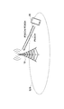
- FIG. 1 is a diagram for explaining a wireless communication system according to an embodiment of the present invention.
- FIG. 6 is a sequence diagram for explaining an example of scheduling in the embodiment of the present invention.
- FIG. 6 is a diagram for explaining an example of cross carrier scheduling in the embodiment of the present invention. It is a figure for explaining an example (1) of scheduling concerning BWP in an embodiment of the invention. It is a figure for explaining an example (2) of scheduling concerning BWP in an embodiment of the invention.
- 6 is a flowchart for explaining an example of a scheduling operation in the embodiment of the present invention. It is a specification change example (1) related to CORESET in the embodiment of the present invention. It is a specification change example (2) related to CORESET in the embodiment of the present invention.
- LTE Long Term Evolution
- LTE-Advanced LTE-Advanced and subsequent schemes (eg, NR) unless otherwise specified.
- SS Synchronization signal
- PSS Primary SS
- SSS Secondary SS
- PBCH Physical broadcast channel
- PRACH Physical Random access channel
- the duplex system may be a TDD (Time Division Duplex) system, an FDD (Frequency Division Duplex) system, or other (for example, Flexible Duplex). May be used.
- “configuring” a wireless parameter or the like may mean that a predetermined value is set in advance (Pre-configure), or the base station device 10 Alternatively, the wireless parameter notified from the user device 20 may be set.
- FIG. 1 is a diagram for explaining a wireless communication system according to an embodiment of the present invention.
- the wireless communication system in the embodiment of the present invention includes a base station device 10 and a user device 20, as shown in FIG. Although one base station apparatus 10 and one user apparatus 20 are shown in FIG. 1, this is an example, and a plurality of each may be provided.
- the base station device 10 is a communication device that provides one or more cells and performs wireless communication with the user device 20.
- the physical resource of the radio signal is defined in the time domain and the frequency domain, the time domain may be defined by the number of OFDM symbols, and the frequency domain may be defined by the number of subcarriers or the number of resource blocks.
- the base station device 10 transmits the synchronization signal and the system information to the user device 20.
- the synchronization signal is, for example, NR-PSS and NR-SSS.
- the system information is transmitted on the NR-PBCH, for example, and is also called broadcast information. As shown in FIG.
- the base station apparatus 10 transmits a control signal or data to the user apparatus 20 by DL (Downlink), and receives a control signal or data from the user apparatus 20 by UL (Uplink). Both the base station device 10 and the user device 20 can perform beamforming to transmit and receive signals. Further, both the base station apparatus 10 and the user apparatus 20 can apply the communication by MIMO (Multiple Input Multiple Output) to DL or UL. Moreover, both the base station apparatus 10 and the user apparatus 20 may communicate via SCell (Secondary Cell) and PCell (Primary Cell) by CA (Carrier Aggregation).
- SCell Secondary Cell
- PCell Primary Cell
- the user device 20 is a communication device having a wireless communication function such as a smartphone, a mobile phone, a tablet, a wearable terminal, and a communication module for M2M (Machine-to-Machine). As shown in FIG. 1, the user equipment 20 receives a control signal or data from the base station apparatus 10 in DL and transmits the control signal or data to the base station apparatus 10 in UL, thereby providing the wireless communication system. Use various communication services.
- the base station device 10 transmits a PDCCH (Physical Downlink Control Channel) or a PDSCH (Physical Downlink Shared Channel) to the user device 20.
- a PDCCH Physical Downlink Control Channel
- a PDSCH Physical Downlink Shared Channel
- information related to scheduling is transmitted to the user equipment 20 via the PDCCH, and data is transmitted to the user equipment 20 via the PDSCH.
- the user apparatus 20 transmits PUSCH (Physical Downlink Shared Channel) to the base station apparatus 10 based on the information regarding scheduling.
- PUSCH Physical Downlink Shared Channel
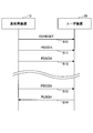
- FIG. 2 is a sequence diagram for explaining an example of scheduling in the embodiment of the present invention.
- a search space for receiving the PDCCH is set by CORESET (Control Resource Set).
- PDSCH or PUSCH scheduling is performed by the PDCCH.
- CORESET sets radio resources in the frequency domain for receiving the PDCCH
- search space sets radio resources in the time domain.
- the radio resource in which the frequency domain and the time domain for receiving the PDCCH are specified is set in the user apparatus 20.
- step S10 the base station device 10 transmits information including CORESET to the user device 20.
- CORESET may be transmitted to the user device 20 by the notification information, or may be transmitted to the user device 20 by the individual control information.
- step S11 the base station device 10 transmits information related to PDSCH scheduling to the user device 20 via the PDCCH.
- the user apparatus 20 specifies the search space for receiving the PDCCH based on CORESET received in step S10. Subsequently, the base station device 10 transmits data to the user device 20 via the PDSCH based on the scheduling transmitted in step S11 (S12). That is, the user apparatus 20 receives data from the base station apparatus 10 via PDSCH based on the scheduling received in step S11.
- step S13 the base station apparatus 10 transmits information regarding PUSCH scheduling to the user apparatus 20 via the PDCCH. Then, the user apparatus 20 transmits data to the base station apparatus 10 via PUSCH based on the scheduling received in step S11 (S14).
- FIG. 3 is a diagram for explaining an example of cross carrier scheduling in the embodiment of the present invention.
- three CC#0, CC#1, and CC#2 are set as a component carrier (CC).
- CC may be replaced with “cell”.
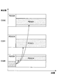
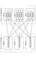
- FIG. 4 is a diagram for explaining an example (1) of scheduling related to BWP in the embodiment of the present invention.
- BWP Bandwidth Part
- BWP#0 is an initial BWP (initial BWP).
- the initial BWP may be specified by an upper layer or may be defined as a part of CORESET of the type 0 PDCCH common search space, and is used when establishing a connection.
- the BWP used is an active BWP. When a plurality of BWPs are set, only one BWP becomes the active BWP.
- the BWP used when the inactivity timer related to BWP expires is the default BWP (default BWP). If the default BWP is not specified by the upper layer, the initial BWP is used as the default BWP.
- BWP may be set to either DL or UL of the cell.
- FIG. 4 is an example in which three BWPs of BWP#0, BWP#1, and BWP#2 are set in the cell to be scheduled and the cell to be scheduled, respectively.
- the BWP shown in FIG. 4 is set to DL for both the scheduling cell and the scheduled cell.
- the Search space #1 set in the BWP #0 of the cell to be scheduled includes the PDCCH that schedules the PDSCH #1 of the BWP #0 of the cell to be scheduled.
- the Search space #2 set in the BWP #0 of the cell to be scheduled includes the PDCCH that schedules the PDSCH #2 of the BWP #1 of the cell to be scheduled.
- the Search space #3 set in the BWP #0 of the cell to be scheduled includes the PDCCH that schedules the PDSCH #3 of the BWP #2 of the cell to be scheduled.
- the Search space #4 set in the BWP #1 of the cell to be scheduled includes the PDCCH scheduling the PDSCH #4 of the BWP #0 of the cell to be scheduled.
- the Search space #5 set in the BWP #1 of the cell to be scheduled includes the PDCCH that schedules the PDSCH #5 of the BWP #1 of the cell to be scheduled.
- the Search space #6 set in the BWP #0 of the cell to be scheduled includes the PDCCH that schedules the PDSCH #6 of the BWP #2 of the cell to be scheduled.
- the Search space #7 set in the BWP #2 of the cell to be scheduled includes the PDCCH scheduling the PDSCH #7 of the BWP #0 of the cell to be scheduled.
- the Search space #8 set in the BWP #2 of the cell to be scheduled includes the PDCCH that schedules the PDSCH #8 of the BWP #1 of the cell to be scheduled.
- the Search space #9 set in the BWP #2 of the cell to be scheduled includes the PDCCH that schedules the PDSCH #9 of the BWP #1 of the cell to be scheduled.
- the search space arranged in one BWP having a cell to be scheduled may correspond to each PDSCH of the cell to be scheduled on a one-to-one basis.
- FIG. 5 is a diagram for explaining an example (2) of scheduling related to BWP in the embodiment of the present invention.
- FIG. 5 is an example in which three BWPs of BWP#0, BWP#1, and BWP#2 are set in the cell to be scheduled and the cell to be scheduled, respectively.
- the BWP shown in FIG. 5 is set to DL for both the scheduling cell and the scheduled cell.
- the Search space #11 set in the BWP #0 of the cell to be scheduled is the PDSCH #1 of the BWP #0 of the cell to be scheduled, and the PDSCH #4 of the BWP #1 of the cell to be scheduled. And a PDCCH that schedules PDSCH #7 of BWP #2 of the cell to be scheduled.
- the Search space #12 set in the BWP #1 of the cell to be scheduled is the PDSCH #2 of the BWP #0 of the cell to be scheduled and the PDSCH of the BWP #1 of the cell to be scheduled. #5 and PDCCH for scheduling PDSCH #8 of BWP #2 of the cell to be scheduled.
- the Search space #13 set in the BWP #0 of the cell to be scheduled is the PDSCH #3 of the BWP #0 of the cell to be scheduled and the PDSCH of the BWP #1 of the cell to be scheduled.
- a search space arranged in one BWP having a cell to be scheduled may correspond to a plurality of PDSCHs arranged in different BWPs having different cells to be scheduled.
- FIG. 6 is a flowchart for explaining an example of scheduling operation according to the embodiment of the present invention.
- An operation example of the user apparatus 20 at the time of cross-carrier scheduling will be described with reference to FIG.
- Step S10 shown in FIG. 2 corresponds to step S101 and step S102.
- step S11 shown in FIG. 2 corresponds to step S111.
- step S12 shown in FIG. 2 corresponds to step S121.
- step S101 the user apparatus 20 receives CORESET from the cell to be scheduled at the time of cross-carrier scheduling.
- CORESET includes information on a search space and parameters for receiving the PDCCH.
- FIG. 7 shows an example (1) of specification change related to CORESET in the embodiment of the present invention.
- the TCI Transmission Configuration Indicator
- DCI Downlink Control Information
- the user device 20 determines that the TCI does not exist or is invalid.
- tci-PresentInDCI is valid in the cell to be scheduled in the case of cross-carrier scheduling. That is, in the scheduling cell in the case of cross carrier scheduling, the TCI field exists in the DCI associated with DL.
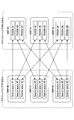
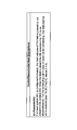
- FIG. 8 shows a specification change example (2) related to CORESET in the embodiment of the present invention.
- the information elements “nofCandidates” and “searchSpaceId” and the condition “SetupOnly” included in the information indicating the search space included in CORESET illustrated in FIG. 8 will be described below.
- the information element “nrofCandidates” is the number of PDCCH candidates for each aggregation level.
- the number of PDCCH candidates applied to the search space of the cell to be scheduled and the aggregation level are determined by “nroofCandidates” included in the search space set in the cell to be scheduled so that the link of the search space is If it is valid, the user device 20 is notified.
- searchSpaceId is an identifier of the search space.
- the “searchSpaceId” is unique in each BWP of the serving cell.
- the search space of the cell to be scheduled is linked to the search space of the cell to be scheduled by assigning the same “searchSpaceId”.
- the search space link between the scheduling cell and the scheduled cell is valid only if the search space is active in both the scheduling cell and the scheduled cell of the corresponding DL BWP.
- SetupOnly indicates a field that is indispensable when setting a new search space.
- “SetupOnly” indicates a field that is indispensable when a new search space is set in the cell to be scheduled, and indicates a field that does not exist in other cases.
- “SetupOnly” indicates that the field is always absent. For example, “SetupOnly” may be applied to the field indicating the identifier of CORESET.
- step S102 the user equipment 20 specifies the search space of the cell to be scheduled from the received CORESET.
- the user device 20 specifies the search space based on “searchSpaceId” included in CORESET.
- step S111 the user apparatus 20 monitors the search space of the specified scheduling cell and receives the PDCCH.
- the user apparatus 20 uses the number of PDCCH candidates for each aggregation level based on “nrofCandidates” included in CORESET for PDCCH decoding.
- step S121 the user apparatus 20 receives the PDSCH of the cell to be scheduled based on the received PDCCH.
- the information element “PDCCH-Config” used in the cell to be scheduled may be set only with “searchSpacesToAddModList” and “searchSpaceToReleaseList” and may not have other fields.
- SearchSpacesToAddModList” and “searchSpacesToReleaseList” are information elements that set or release search space.
- the user apparatus 20 receives the PDCCH by monitoring the search space of the cell to be scheduled, based on the number of the PDCCH candidates and the information specifying the search space included in CORESET in the cross carrier scheduling,
- the PDSCH of the cell scheduled based on the PDCCH can be received.
- the base station device 10 and the user device 20 include a function for implementing the above-described embodiment. However, each of the base station device 10 and the user device 20 may have only some of the functions in the embodiment.
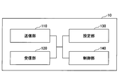
- FIG. 9 is a diagram illustrating an example of a functional configuration of the base station device 10.
- the base station device 10 includes a transmission unit 110, a reception unit 120, a setting unit 130, and a control unit 140.
- the functional configuration shown in FIG. 9 is merely an example. As long as the operation according to the embodiment of the present invention can be executed, the function classification and the names of the function units may be any names.
- the transmitting unit 110 includes a function of generating a signal to be transmitted to the user device 20 side and wirelessly transmitting the signal.
- the receiving unit 120 includes a function of receiving various signals transmitted from the user device 20 and acquiring, for example, information of a higher layer from the received signals. Further, the transmission unit 110 has a function of transmitting NR-PSS, NR-SSS, NR-PBCH, DL/UL control signal, DL/UL data signal, etc. to the user apparatus 20.
- the setting unit 130 stores preset setting information and various setting information to be transmitted to the user device 20 in the storage device, and reads it from the storage device as necessary.
- the contents of the setting information are, for example, settings related to the search space of the user device 20, settings related to scheduling, and the like.
- the control unit 140 schedules the user device 20 and controls transmission of downlink data and reception of uplink data, as described in the embodiment.
- the functional unit related to signal transmission in the control unit 140 may be included in the transmission unit 110, and the functional unit related to signal reception in the control unit 140 may be included in the reception unit 120.
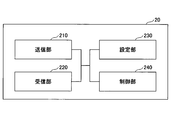
- FIG. 10 is a diagram showing an example of a functional configuration of the user device 20.
- the user device 20 includes a transmission unit 210, a reception unit 220, a setting unit 230, and a control unit 240.
- the functional configuration shown in FIG. 10 is merely an example. As long as the operation according to the embodiment of the present invention can be executed, the function classification and the names of the function units may be any names.
- the transmitting unit 210 creates a transmission signal from the transmission data and wirelessly transmits the transmission signal.
- the reception unit 220 wirelessly receives various signals and acquires signals of higher layers from the received physical layer signals. Further, the receiving unit 220 has a function of receiving NR-PSS, NR-SSS, NR-PBCH, DL/UL/SL control signals and the like transmitted from the base station apparatus 10.
- the transmission unit 210 performs P2CH communication to other user apparatuses 20 by using PSCCH (Physical Sidelink Control Channel), PSSCH (Physical Sidelink Shared Channel), PSDCH (Physical Sidelink Discovery Channel), and PSBCH (Physical Sidelink Broadcast Channel). ) Etc., and the receiving part 120 receives PSCCH, PSSCH, PSDCH, PSBCH, etc. from the other user apparatus 20.
- PSCCH Physical Sidelink Control Channel
- PSSCH Physical Sidelink Shared Channel
- PSDCH Physical Sidelink Discovery Channel
- PSBCH Physical Sidelink Broadcast Channel
- the setting unit 230 stores various setting information received from the base station device 10 or the user device 20 by the receiving unit 220 in a storage device, and reads it from the storage device as necessary.
- the setting unit 230 also stores preset setting information.
- the contents of the setting information are, for example, settings related to the search space of the user device 20, settings related to scheduling, and the like.
- the control unit 240 controls the reception of downlink data and the transmission of uplink data based on the scheduling acquired from the base station device 10, as described in the embodiment. In addition, the control unit 240 executes control related to the search space for receiving the control information.
- the functional unit related to signal transmission in the control unit 240 may be included in the transmission unit 210, and the functional unit related to signal reception in the control unit 240 may be included in the reception unit 220.
- each functional block may be realized by using one device physically or logically coupled, or directly or indirectly (for example, two or more devices physically or logically separated). , Wired, wireless, etc.) and may be implemented using these multiple devices.
- the functional blocks may be realized by combining the one device or the plurality of devices with software.
- Functions include judgment, decision, judgment, calculation, calculation, processing, derivation, investigation, search, confirmation, reception, transmission, output, access, resolution, selection, selection, establishment, comparison, assumption, expectation, observation, Broadcasting, notifying, communicating, forwarding, configuring, reconfiguring, allocating, mapping, assigning, etc., but not limited to these.
- I can't.
- functional blocks (components) that function transmission are called a transmitting unit and a transmitter.
- the implementation method is not particularly limited.
- the base station device 10, the user device 20, and the like according to the embodiment of the present disclosure may function as a computer that performs the process of the wireless communication method of the present disclosure.
- FIG. 11 is a diagram illustrating an example of a hardware configuration of the base station device 10 and the user device 20 according to the embodiment of the present disclosure.
- the base station device 10 and the user device 20 described above are physically configured as a computer device including a processor 1001, a storage device 1002, an auxiliary storage device 1003, a communication device 1004, an input device 1005, an output device 1006, a bus 1007, and the like. May be done.
- the word “apparatus” can be read as a circuit, device, unit, or the like.
- the hardware configurations of the base station device 10 and the user device 20 may be configured to include one or a plurality of each device illustrated in the figure, or may be configured not to include some devices.
- Each function in the base station device 10 and the user device 20 causes a predetermined software (program) to be loaded onto hardware such as the processor 1001, the storage device 1002, etc., so that the processor 1001 performs an arithmetic operation and the communication by the communication device 1004. It is realized by controlling and/or controlling at least one of reading and writing of data in the storage device 1002 and the auxiliary storage device 1003.
- the processor 1001 operates an operating system to control the entire computer, for example.
- the processor 1001 may be configured by a central processing unit (CPU) including an interface with peripheral devices, a control device, a calculation device, a register, and the like.
- CPU central processing unit
- the control unit 140 and the control unit 240 described above may be realized by the processor 1001.
- the processor 1001 reads a program (program code), software module, data, or the like from at least one of the auxiliary storage device 1003 and the communication device 1004 into the storage device 1002, and executes various processes according to these.
- a program that causes a computer to execute at least part of the operations described in the above-described embodiments is used.
- the control unit 140 of the base station device 10 illustrated in FIG. 9 may be realized by a control program stored in the storage device 1002 and operated by the processor 1001.
- the control unit 240 of the user device 20 illustrated in FIG. 10 may be realized by a control program stored in the storage device 1002 and operated by the processor 1001.
- the various processes described above are executed by one processor 1001, they may be executed simultaneously or sequentially by two or more processors 1001.
- the processor 1001 may be implemented by one or more chips.
- the program may be transmitted from the network via an electric communication line.
- the storage device 1002 is a computer-readable recording medium, and is, for example, at least one of ROM (Read Only Memory), EPROM (Erasable Programmable ROM), EEPROM (Electrically Erasable Programmable ROM), RAM (Random Access Memory), and the like. It may be configured.
- the storage device 1002 may be called a register, a cache, a main memory (main storage device), or the like.
- the storage device 1002 can store an executable program (program code), a software module, or the like for implementing the communication method according to the embodiment of the present disclosure.
- the auxiliary storage device 1003 is a computer-readable recording medium, and is, for example, an optical disk such as a CD-ROM (Compact Disc ROM), a hard disk drive, a flexible disk, a magneto-optical disk (for example, a compact disk, a digital versatile disk, a Blu disk). -Ray disk), smart card, flash memory (eg card, stick, key drive), floppy disk, magnetic strip, etc.
- the above-mentioned storage medium may be, for example, a database including at least one of the storage device 1002 and the auxiliary storage device 1003, a server, or another appropriate medium.
- the communication device 1004 is hardware (transmission/reception device) for performing communication between computers via at least one of a wired network and a wireless network, and is also called, for example, a network device, a network controller, a network card, a communication module, or the like.
- the communication device 1004 includes, for example, a high frequency switch, a duplexer, a filter, a frequency synthesizer, etc. in order to realize at least one of a frequency division duplex (FDD: Frequency Division Duplex) and a time division duplex (TDD: Time Division Duplex). May be composed of
- FDD Frequency Division Duplex
- TDD Time Division Duplex
- the transmitter/receiver may be implemented by physically or logically separating the transmitter and the receiver.
- the input device 1005 is an input device (for example, a keyboard, a mouse, a microphone, a switch, a button, a sensor, etc.) that receives an input from the outside.
- the output device 1006 is an output device (for example, a display, a speaker, an LED lamp, etc.) that outputs to the outside.
- the input device 1005 and the output device 1006 may be integrated (for example, a touch panel).
- each device such as the processor 1001 and the storage device 1002 is connected by a bus 1007 for communicating information.
- the bus 1007 may be configured by using a single bus, or may be configured by using a different bus for each device.
- the base station device 10 and the user device 20 include a microprocessor, a digital signal processor (DSP: Digital Signal Processor), an ASIC (Application Specific Integrated Circuit), a PLD (Programmable Logic Device), an FPGA (Field Programmable Gate Array), and the like. It may be configured to include hardware, and the hardware may implement some or all of the functional blocks. For example, the processor 1001 may be implemented using at least one of these hardware.
- DSP Digital Signal Processor
- ASIC Application Specific Integrated Circuit
- PLD Programmable Logic Device
- FPGA Field Programmable Gate Array
- a control resource set is received from a cell to be scheduled in cross carrier scheduling, and a search space of the cell to be scheduled is specified based on the control resource set.
- a user apparatus having a receiving unit that receives a PDSCH (Physical Downlink Shared Channel) from a scheduled cell in cross-carrier scheduling based on the PDCCH is provided.
- PDSCH Physical Downlink Shared Channel
- the user equipment 20 receives the PDCCH by monitoring the search space of the cell to be scheduled based on the information specifying the search space included in CORESET and the number of PDCCH candidates.
- the PDSCH of the cell scheduled based on the PDCCH can be received. That is, it is possible to improve the efficiency of the decoding process at the time of cross-carrier scheduling.
- the number of PDCCH candidates may be acquired from the search space set in the cell to be scheduled.
- the user apparatus 20 can improve the efficiency of the decoding process by acquiring the number of PDCCH candidates when the search space ring is valid in cross carrier scheduling.
- the information for setting the PDCCH applied to the cell to be scheduled may include only information related to the search space.
- the user apparatus 20 can improve communication efficiency by preventing unnecessary information from being acquired in the scheduled cell in cross-carrier scheduling.
- a plurality of search spaces including a PDCCH corresponding to the PDSCH of each BWP of the cell to be scheduled in a one-to-one correspondence may be set.
- one search space including a plurality of PDCCHs corresponding to the PDSCH of each BWP of the cell to be scheduled may be set.
- the user apparatus 20 can perform scheduling by using one search space among a plurality of BWPs in cross carrier scheduling.
- a control resource set is transmitted in a scheduling cell in cross-carrier scheduling, a search space of the scheduling cell is set based on the control resource set, and a cell to be scheduled is set.
- a control unit that transmits the number of PDCCH (Physical Downlink Control Channel) candidates to the user equipment in the search space set to, and transmits the PDCCH included in the search space of the cell to be scheduled to the user equipment, Then, there is provided a base station apparatus having a transmission unit that transmits PDSCH (Physical Downlink Shared Channel) to the user apparatus in a cell to be scheduled in cross carrier scheduling.
- PDSCH Physical Downlink Shared Channel
- the user equipment 20 receives the PDCCH by monitoring the search space of the cell to be scheduled based on the information specifying the search space included in CORESET and the number of PDCCH candidates.
- the PDSCH of the cell scheduled based on the PDCCH can be received. That is, it is possible to improve the efficiency of the decoding process at the time of cross-carrier scheduling.
- the operation of the plurality of functional units may be physically performed by one component, or the operation of one functional unit may be physically performed by the plurality of components.
- the order of processing may be changed as long as there is no contradiction.
- the base station apparatus 10 and the user apparatus 20 are described using functional block diagrams for convenience of processing description, such an apparatus may be realized by hardware, software, or a combination thereof.
- the software operated by the processor included in the base station device 10 according to the embodiment of the present invention and the software operated by the processor included in the user device 20 according to the embodiment of the present invention are respectively a random access memory (RAM), a flash memory, and a read memory. It may be stored in a dedicated memory (ROM), EPROM, EEPROM, register, hard disk (HDD), removable disk, CD-ROM, database, server, or any other suitable storage medium.
- the notification of information is not limited to the mode/embodiment described in the present disclosure, and may be performed using another method.
- information is notified by physical layer signaling (for example, DCI (Downlink Control Information), UCI (Uplink Control Information)), upper layer signaling (for example, RRC (Radio Resource Control) signaling, MAC (Medium Access Control) signaling, It may be implemented by broadcast information (MIB (Master Information Block), SIB (System Information Block)), other signals, or a combination thereof, and RRC signaling may be called an RRC message, for example, RRC message. It may be a connection setup (RRC Connection Setup) message, an RRC connection reconfiguration message, or the like.
- LTE Long Term Evolution
- LTE-A Long Term Evolution-Advanced
- SUPER 3G IMT-Advanced
- 4G 4th generation mobile communication system
- 5G 5th generation mobile communication system
- FRA Fluture Radio Access
- NR new Radio
- W-CDMA registered trademark
- GSM registered trademark
- CDMA2000 Code Division Multiple Access 2000
- UMB Universal Mobile Broadband
- IEEE 802.11 Wi-Fi (registered trademark)
- IEEE 802.16 WiMAX (registered trademark)
- IEEE 802.20 UWB (Ultra-WideBand
- Bluetooth registered trademark
- the specific operation that is performed by the base station device 10 in this specification may be performed by its upper node in some cases.
- various operations performed for communication with the user device 20 are other than the base station device 10 and the base station device 10. It is clear that it can be performed by at least one of the network nodes of (for example, but not limited to, MME or S-GW, etc.).
- the other network node may be a combination of a plurality of other network nodes (for example, MME and S-GW). Good.
- Information, signals, etc. described in the present disclosure may be output from the upper layer (or lower layer) to the lower layer (or upper layer). Input/output may be performed via a plurality of network nodes.
- Information that has been input and output may be stored in a specific location (for example, memory), or may be managed using a management table. Information that is input/output may be overwritten, updated, or added. The output information and the like may be deleted. The input information and the like may be transmitted to another device.
- the determination according to the present disclosure may be performed based on a value (0 or 1) represented by 1 bit, may be performed based on a boolean value (Boolean: true or false), and may be performed by comparing numerical values (for example, , Comparison with a predetermined value).
- software, instructions, information, etc. may be sent and received via a transmission medium.
- the software uses a website using at least one of wired technology (coaxial cable, optical fiber cable, twisted pair, digital subscriber line (DSL), etc.) and wireless technology (infrared, microwave, etc.), When sent from a server, or other remote source, at least one of these wired and wireless technologies are included within the definition of transmission medium.
- wired technology coaxial cable, optical fiber cable, twisted pair, digital subscriber line (DSL), etc.
- wireless technology infrared, microwave, etc.
- data, instructions, commands, information, signals, bits, symbols, chips, etc. that may be referred to throughout the above description include voltage, current, electromagnetic waves, magnetic fields or magnetic particles, optical fields or photons, or any of these. May be represented by a combination of
- At least one of the channel and the symbol may be a signal (signaling).
- the signal may also be a message.
- a component carrier CC:Component Carrier
- CC Component Carrier
- system and “network” used in this disclosure are used interchangeably.
- the information, parameters, etc. described in the present disclosure may be represented by using an absolute value, may be represented by using a relative value from a predetermined value, or by using other corresponding information. May be represented.
- the radio resources may be those indicated by the index.
- base station Base Station
- radio base station base station
- base station device fixed station
- NodeB NodeB
- eNodeB eNodeB
- GNB nodeB
- Access point access point
- transmission point transmission point
- reception point transmission/reception point
- cell cell
- vector Terms such as “cell group”, “carrier”, “component carrier” may be used interchangeably.
- a base station may be referred to by terms such as macro cell, small cell, femto cell, and pico cell.
- a base station can accommodate one or more (eg, three) cells.
- the entire coverage area of the base station can be divided into multiple smaller areas, each smaller area being a base station subsystem (eg, a small indoor base station (RRH: Communication service can also be provided by Remote Radio Head.
- RRH small indoor base station
- the term "cell” or “sector” means a part or the whole of the coverage area of at least one of the base station and the base station subsystem that perform communication service in this coverage. Refers to.
- MS Mobile Station
- UE User Equipment
- Mobile stations are defined by those skilled in the art as subscriber stations, mobile units, subscriber units, wireless units, remote units, mobile devices, wireless devices, wireless communication devices, remote devices, mobile subscriber stations, access terminals, mobile terminals, wireless. It may also be referred to as a terminal, remote terminal, handset, user agent, mobile client, client, or some other suitable term.
- At least one of the base station and the mobile station may be called a transmission device, a reception device, a communication device, or the like.
- the base station and the mobile station may be a device mounted on a mobile body, the mobile body itself, or the like.
- the moving body may be a vehicle (eg, car, airplane, etc.), an unmanned moving body (eg, drone, self-driving car, etc.), or a robot (manned or unmanned).
- At least one of the base station and the mobile station also includes a device that does not necessarily move during a communication operation.
- at least one of the base station and the mobile station may be an IoT (Internet of Things) device such as a sensor.
- IoT Internet of Things
- the base station in the present disclosure may be replaced by the user terminal.
- the communication between the base station and the user terminal is replaced with communication between a plurality of user devices 20 (eg, may be referred to as D2D (Device-to-Device), V2X (Vehicle-to-Everything), etc.)
- a plurality of user devices 20 eg, may be referred to as D2D (Device-to-Device), V2X (Vehicle-to-Everything), etc.
- the user device 20 may have the function of the base station device 10 described above.
- the wording such as “up” and “down” may be replaced with the wording corresponding to the terminal-to-terminal communication (for example, “side”).
- the uplink channel and the downlink channel may be replaced with the side channel.
- the user terminal in the present disclosure may be replaced by the base station.
- the base station may have the function of the above-mentioned user terminal.
- determining and “determining” as used in this disclosure may encompass a wide variety of actions.
- “Judgment” and “decision” are, for example, judgment, calculating, computing, processing, deriving, investigating, and looking up, search, inquiry. (Eg, searching in a table, a database, or another data structure), considering ascertaining as “judging” or “deciding”, and the like.
- “decision” and “decision” include receiving (eg, receiving information), transmitting (eg, transmitting information), input (input), output (output), access (accessing) (for example, accessing data in a memory) can be regarded as “judging” and “deciding”.
- judgment and “decision” are considered to be “judgment” and “decision” when things such as resolving, selecting, selecting, establishing, establishing, and comparing are done. May be included. That is, the “judgment” and “decision” may include considering some action as “judgment” and “decision”. In addition, “determination (decision)” may be read as “assuming,” “expecting,” “considering,” and the like.
- connection means any direct or indirect connection or coupling between two or more elements, and It may include the presence of one or more intermediate elements between two elements that are “connected” or “coupled”.
- the connections or connections between the elements may be physical, logical, or a combination thereof.
- connection may be read as “access”.
- two elements are in the radio frequency domain, with at least one of one or more wires, cables and printed electrical connections, and as some non-limiting and non-exhaustive examples. , Can be considered to be “connected” or “coupled” to each other, such as with electromagnetic energy having wavelengths in the microwave and light (both visible and invisible) regions.
- the reference signal may be abbreviated as RS (Reference Signal), or may be referred to as a pilot (Pilot) depending on the applied standard.
- RS Reference Signal
- Pilot pilot
- the phrase “based on” does not mean “based only on,” unless expressly specified otherwise. In other words, the phrase “based on” means both "based only on” and “based at least on.”
- references to elements using the designations “first,” “second,” etc. as used in this disclosure does not generally limit the amount or order of those elements. These designations may be used in this disclosure as a convenient way to distinguish between two or more elements. Thus, references to the first and second elements do not mean that only two elements may be employed, or that the first element must precede the second element in any way.
- a radio frame may be composed of one or more frames in the time domain. Each frame or frames in the time domain may be referred to as a subframe. A subframe may also be composed of one or more slots in the time domain. The subframe may have a fixed time length (for example, 1 ms) that does not depend on numerology.
- Numerology may be a communication parameter applied to at least one of transmission and reception of a certain signal or channel.
- Numerology includes, for example, subcarrier spacing (SCS: SubCarrier Spacing), bandwidth, symbol length, cyclic prefix length, transmission time interval (TTI: Transmission Time Interval), number of symbols per TTI, radio frame configuration, transceiver At least one of a specific filtering process performed in the frequency domain and a specific windowing process performed by the transceiver in the time domain may be shown.
- a slot may be composed of one or more symbols (OFDM (Orthogonal Frequency Division Multiplexing) symbol, SC-FDMA (Single Carrier Frequency Division Multiple Access) symbol, etc.) in the time domain.
- a slot may be a time unit based on numerology.
- a slot may include multiple minislots. Each minislot may be composed of one or more symbols in the time domain. The minislot may also be called a subslot. Minislots may be configured with a smaller number of symbols than slots.
- a PDSCH (or PUSCH) transmitted in a time unit larger than a minislot may be referred to as PDSCH (or PUSCH) mapping type A.
- the PDSCH (or PUSCH) transmitted using the minislot may be referred to as PDSCH (or PUSCH) mapping type B.
- Radio frame, subframe, slot, minislot, and symbol all represent the time unit for signal transmission. Radio frames, subframes, slots, minislots, and symbols may have different names corresponding to them.
- one subframe may be called a transmission time interval (TTI)
- TTI transmission time interval
- TTI transmission time interval
- TTI transmission time interval
- TTI transmission time interval
- TTI means, for example, a minimum time unit of scheduling in wireless communication.
- the base station performs scheduling to allocate radio resources (frequency bandwidth that can be used in each user device 20, transmission power, etc.) to each user device 20 in units of TTI.
- the definition of TTI is not limited to this.
- the TTI may be a transmission time unit such as a channel-encoded data packet (transport block), a code block, a codeword, or a processing unit such as scheduling or link adaptation.
- transport block channel-encoded data packet
- code block code block
- codeword codeword
- processing unit such as scheduling or link adaptation.
- one slot or one minislot is called a TTI
- one or more TTIs may be the minimum time unit for scheduling.
- the number of slots (minislot number) that constitutes the minimum time unit of the scheduling may be controlled.
- a TTI having a time length of 1 ms may be called a normal TTI (TTI in LTE Rel. 8-12), a normal TTI, a long TTI, a normal subframe, a normal subframe, a long subframe, a slot, or the like.
- a TTI shorter than the normal TTI may be called a shortened TTI, a short TTI, a partial TTI (partial or fractional TTI), a shortened subframe, a short subframe, a minislot, a subslot, a slot, and the like.
- a long TTI (eg, normal TTI, subframe, etc.) may be read as a TTI having a time length of more than 1 ms, and a short TTI (eg, shortened TTI, etc.) is less than the TTI length of the long TTI and 1 ms. It may be read as a TTI having the above TTI length.
- a resource block is a resource allocation unit in the time domain and the frequency domain, and may include one or a plurality of continuous subcarriers in the frequency domain.
- the number of subcarriers included in the RB may be the same regardless of the numerology, and may be 12, for example.
- the number of subcarriers included in the RB may be determined based on numerology.
- the time domain of RB may include one or more symbols, and may be one slot, one minislot, one subframe, or one TTI in length.
- Each 1 TTI, 1 subframe, etc. may be configured with one or a plurality of resource blocks.
- one or more RBs are a physical resource block (PRB: Physical RB), subcarrier group (SCG: Sub-Carrier Group), resource element group (REG: Resource Element Group), PRB pair, RB pair, etc. May be called.
- PRB Physical resource block
- SCG Sub-Carrier Group
- REG Resource Element Group
- PRB pair RB pair, etc. May be called.
- the resource block may be composed of one or more resource elements (RE: Resource Element).
- RE Resource Element
- one RE may be a radio resource area of one subcarrier and one symbol.
- a bandwidth part (may be called a partial bandwidth) may represent a subset of consecutive common RBs (common resource blocks) for a certain numerology in a certain carrier.
- the common RB may be specified by the index of the RB based on the common reference point of the carrier.
- PRBs may be defined in a BWP and numbered within that BWP.
- BWP may include BWP for UL (UL BWP) and BWP for DL (DL BWP).
- BWP may include BWP for UL (UL BWP) and BWP for DL (DL BWP).
- One or more BWPs may be configured in one carrier for the UE.
- At least one of the configured BWPs may be active, and the UE does not have to expect to send and receive a given signal/channel outside the active BWP.
- “cell”, “carrier”, and the like in the present disclosure may be read as “BWP”.
- the structure of the radio frame, subframe, slot, minislot, symbol, etc. described above is merely an example.
- the number of subframes included in a radio frame, the number of slots per subframe or radio frame, the number of minislots included in a slot, the number of symbols and RBs included in a slot or minislot, and included in RBs The number of subcarriers, the number of symbols in the TTI, the symbol length, the cyclic prefix (CP: Cyclic Prefix) length, and the like can be variously changed.
- the term “A and B are different” may mean “A and B are different from each other”.
- the term may mean that “A and B are different from C”.
- the terms “remove”, “coupled” and the like may be construed similarly as “different”.
- the notification of the predetermined information (for example, the notification of “being X”) is not limited to the explicit notification, and is performed implicitly (for example, the notification of the predetermined information is not performed). Good.
- CORESET is an example of a control resource set.
- PDCCH-Config is an example of information for setting the PDCCH.
- base station device 110 transmission unit 120 reception unit 130 setting unit 140 control unit 20 user device 210 transmission unit 220 reception unit 230 setting unit 240 control unit 1001 processor 1002 storage device 1003 auxiliary storage device 1004 communication device 1005 input device 1006 output device
Landscapes
- Engineering & Computer Science (AREA)
- Signal Processing (AREA)
- Computer Networks & Wireless Communication (AREA)
- Physics & Mathematics (AREA)
- Mathematical Physics (AREA)
- Mobile Radio Communication Systems (AREA)
Abstract
Priority Applications (6)
| Application Number | Priority Date | Filing Date | Title |
|---|---|---|---|
| PCT/JP2019/003212 WO2020157873A1 (fr) | 2019-01-30 | 2019-01-30 | Dispositif d'utilisateur et dispositif de station de base |
| JP2020569243A JP7250048B2 (ja) | 2019-01-30 | 2019-01-30 | 端末、基地局、通信方法及び無線通信システム |
| BR112021013119-1A BR112021013119A2 (pt) | 2019-01-30 | 2019-01-30 | Equipamento de usuário e aparelho de estação base |
| EP19913367.9A EP3920497A4 (fr) | 2019-01-30 | 2019-01-30 | Dispositif d'utilisateur et dispositif de station de base |
| US17/424,366 US20220116977A1 (en) | 2019-01-30 | 2019-01-30 | User equipment and base station apparatus |
| CN201980090395.XA CN113383522B (zh) | 2019-01-30 | 2019-01-30 | 用户装置以及基站装置 |
Applications Claiming Priority (1)
| Application Number | Priority Date | Filing Date | Title |
|---|---|---|---|
| PCT/JP2019/003212 WO2020157873A1 (fr) | 2019-01-30 | 2019-01-30 | Dispositif d'utilisateur et dispositif de station de base |
Publications (1)
| Publication Number | Publication Date |
|---|---|
| WO2020157873A1 true WO2020157873A1 (fr) | 2020-08-06 |
Family
ID=71841268
Family Applications (1)
| Application Number | Title | Priority Date | Filing Date |
|---|---|---|---|
| PCT/JP2019/003212 WO2020157873A1 (fr) | 2019-01-30 | 2019-01-30 | Dispositif d'utilisateur et dispositif de station de base |
Country Status (6)
| Country | Link |
|---|---|
| US (1) | US20220116977A1 (fr) |
| EP (1) | EP3920497A4 (fr) |
| JP (1) | JP7250048B2 (fr) |
| CN (1) | CN113383522B (fr) |
| BR (1) | BR112021013119A2 (fr) |
| WO (1) | WO2020157873A1 (fr) |
Families Citing this family (1)
| Publication number | Priority date | Publication date | Assignee | Title |
|---|---|---|---|---|
| US11304218B2 (en) * | 2019-07-24 | 2022-04-12 | Samsung Electronics Co., Ltd. | Control signaling design for improved resource utilization |
Citations (3)
| Publication number | Priority date | Publication date | Assignee | Title |
|---|---|---|---|---|
| JP2018026865A (ja) * | 2014-03-28 | 2018-02-15 | エルジー エレクトロニクス インコーポレイティド | 機械タイプ通信を支援する無線接続システムにおいてチャネル状態情報送信方法及び装置 |
| WO2018230139A1 (fr) * | 2017-06-16 | 2018-12-20 | パナソニック インテレクチュアル プロパティ コーポレーション オブ アメリカ | Station de base, terminal et procédé de communication |
| WO2019009665A1 (fr) * | 2017-07-06 | 2019-01-10 | Lg Electronics Inc. | Procédé et appareil permettant de gérer de multiples numérologies dans un système de communication sans fil |
Family Cites Families (16)
| Publication number | Priority date | Publication date | Assignee | Title |
|---|---|---|---|---|
| US8675565B2 (en) * | 2009-05-14 | 2014-03-18 | Lg Electronics Inc. | Device and method for monitoring the control channel in a multicarrier system |
| CN103580833B (zh) * | 2012-07-25 | 2018-08-14 | 上海诺基亚贝尔股份有限公司 | 一种用于配置载波聚合的方法和设备 |
| US9628237B2 (en) * | 2012-10-21 | 2017-04-18 | Lg Electronics Inc. | Method and device for monitoring downlink control channel in wireless communication system |
| WO2016048111A2 (fr) * | 2014-09-27 | 2016-03-31 | 엘지전자 주식회사 | Procédé de surveillance mis en œuvre par un terminal dans un système de communication sans fil prenant en charge une agrégation de porteuses, et dispositif associé |
| CN110476449B (zh) * | 2017-03-24 | 2023-02-21 | 瑞典爱立信有限公司 | 用于amm测量的csi-rs |
| US10601551B2 (en) * | 2017-05-04 | 2020-03-24 | Sharp Kabushiki Kaisha | Hybrid automatic repeat request for uplink ultra-reliable and low-latency communications |
| US10972990B2 (en) * | 2017-09-11 | 2021-04-06 | Qualcomm Incorporated | System information rate matching |
| CN111030799B (zh) * | 2017-09-14 | 2021-03-05 | Oppo广东移动通信有限公司 | 一种确定时域资源的方法、设备、存储介质及系统 |
| US10790954B2 (en) * | 2017-10-25 | 2020-09-29 | Qualcomm Incorporated | Implicit acknowledgment (ACK) mapping |
| CN110049561B (zh) * | 2018-01-16 | 2023-03-28 | 华硕电脑股份有限公司 | 不连续传送指示的准共址关联指示的方法和设备 |
| US11109368B2 (en) * | 2018-02-13 | 2021-08-31 | Sharp Kabushiki Kaisha | User equipments, base stations and methods for downlink semi-persistent scheduling |
| AU2019222457B2 (en) * | 2018-02-13 | 2023-11-02 | FG Innovation Company Limited | User equipments, base stations and methods for downlink semi-persistent scheduling |
| EP3753156A4 (fr) * | 2018-02-14 | 2021-11-10 | Sharp Kabushiki Kaisha | Équipements utilisateur, stations de base et procédés de transmission en liaison montante sans autorisation |
| WO2019215876A1 (fr) * | 2018-05-10 | 2019-11-14 | 株式会社Nttドコモ | Terminal utilisateur |
| US11457434B2 (en) * | 2018-06-22 | 2022-09-27 | Sharp Laboratories Of America, Inc. | User equipments, base stations and methods for time-domain resource allocation |
| CN110830151B (zh) * | 2018-08-07 | 2021-06-15 | 华为技术有限公司 | 反馈信息的传输方法和装置 |
-
2019
- 2019-01-30 JP JP2020569243A patent/JP7250048B2/ja active Active
- 2019-01-30 BR BR112021013119-1A patent/BR112021013119A2/pt unknown
- 2019-01-30 WO PCT/JP2019/003212 patent/WO2020157873A1/fr unknown
- 2019-01-30 EP EP19913367.9A patent/EP3920497A4/fr active Pending
- 2019-01-30 US US17/424,366 patent/US20220116977A1/en active Pending
- 2019-01-30 CN CN201980090395.XA patent/CN113383522B/zh active Active
Patent Citations (3)
| Publication number | Priority date | Publication date | Assignee | Title |
|---|---|---|---|---|
| JP2018026865A (ja) * | 2014-03-28 | 2018-02-15 | エルジー エレクトロニクス インコーポレイティド | 機械タイプ通信を支援する無線接続システムにおいてチャネル状態情報送信方法及び装置 |
| WO2018230139A1 (fr) * | 2017-06-16 | 2018-12-20 | パナソニック インテレクチュアル プロパティ コーポレーション オブ アメリカ | Station de base, terminal et procédé de communication |
| WO2019009665A1 (fr) * | 2017-07-06 | 2019-01-10 | Lg Electronics Inc. | Procédé et appareil permettant de gérer de multiples numérologies dans un système de communication sans fil |
Non-Patent Citations (4)
| Title |
|---|
| 3GPP TS 38.213, December 2018 (2018-12-01) |
| 3GPP TS 38.214, December 2018 (2018-12-01) |
| 3GPP TS 38.300, December 2018 (2018-12-01) |
| See also references of EP3920497A4 |
Also Published As
| Publication number | Publication date |
|---|---|
| JPWO2020157873A1 (ja) | 2021-12-02 |
| EP3920497A4 (fr) | 2022-08-17 |
| CN113383522A (zh) | 2021-09-10 |
| US20220116977A1 (en) | 2022-04-14 |
| BR112021013119A2 (pt) | 2021-09-08 |
| JP7250048B2 (ja) | 2023-03-31 |
| CN113383522B (zh) | 2024-02-09 |
| EP3920497A1 (fr) | 2021-12-08 |
Similar Documents
| Publication | Publication Date | Title |
|---|---|---|
| JP2023156440A (ja) | 端末、基地局及び通信方法 | |
| JP2024024117A (ja) | 端末及び通信方法 | |
| WO2020230201A1 (fr) | Dispositif utilisateur et dispositif de station de base | |
| JP7369211B2 (ja) | 端末、基地局及び通信方法 | |
| WO2021140673A1 (fr) | Terminal et procédé de communication | |
| JP7073529B2 (ja) | 端末、基地局及び通信方法 | |
| WO2020157873A1 (fr) | Dispositif d'utilisateur et dispositif de station de base | |
| WO2020157874A1 (fr) | Dispositif utilisateur et dispositif de station de base | |
| WO2020171182A1 (fr) | Dispositif utilisateur et dispositif de station de base | |
| WO2021038920A1 (fr) | Terminal, station de base et procédé de communication | |
| JP7201786B2 (ja) | 端末、基地局、通信方法及び無線通信システム | |
| JP7170842B2 (ja) | ユーザ装置及び基地局装置 | |
| JP7203199B2 (ja) | 端末、基地局及び通信方法 | |
| WO2020161824A1 (fr) | Dispositif utilisateur et dispositif de station de base | |
| WO2020090069A1 (fr) | Dispositif utilisateur et dispositif de station de base | |
| WO2020194636A1 (fr) | Équipement utilisateur | |
| JP7491905B2 (ja) | 端末、基地局装置、通信方法及びシステム | |
| WO2021140676A1 (fr) | Terminal et procédé de communication | |
| WO2022030022A1 (fr) | Terminal et procédé de communication | |
| WO2022208635A1 (fr) | Terminal et procédé de communication | |
| WO2022085169A1 (fr) | Terminal et procédé de communication | |
| WO2022085203A1 (fr) | Terminal, et procédé de communication | |
| WO2020202562A1 (fr) | Dispositif utilisateur et dispositif de station de base | |
| WO2020174552A1 (fr) | Dispositif utilisateur et procédé de communication | |
| WO2020179037A1 (fr) | Dispositif utilisateur et dispositif de station de base |
Legal Events
| Date | Code | Title | Description |
|---|---|---|---|
| 121 | Ep: the epo has been informed by wipo that ep was designated in this application |
Ref document number: 19913367 Country of ref document: EP Kind code of ref document: A1 |
|
| ENP | Entry into the national phase |
Ref document number: 2020569243 Country of ref document: JP Kind code of ref document: A |
|
| REG | Reference to national code |
Ref country code: BR Ref legal event code: B01A Ref document number: 112021013119 Country of ref document: BR |
|
| NENP | Non-entry into the national phase |
Ref country code: DE |
|
| ENP | Entry into the national phase |
Ref document number: 2019913367 Country of ref document: EP Effective date: 20210830 |
|
| ENP | Entry into the national phase |
Ref document number: 112021013119 Country of ref document: BR Kind code of ref document: A2 Effective date: 20210701 |