WO2021214894A1 - Terminal et procédé de communication - Google Patents
Terminal et procédé de communication Download PDFInfo
- Publication number
- WO2021214894A1 WO2021214894A1 PCT/JP2020/017266 JP2020017266W WO2021214894A1 WO 2021214894 A1 WO2021214894 A1 WO 2021214894A1 JP 2020017266 W JP2020017266 W JP 2020017266W WO 2021214894 A1 WO2021214894 A1 WO 2021214894A1
- Authority
- WO
- WIPO (PCT)
- Prior art keywords
- terminal
- iot
- base station
- communication
- resource
- Prior art date
Links
- 238000004891 communication Methods 0.000 title claims abstract description 65
- 238000000034 method Methods 0.000 title claims description 31
- 230000005540 biological transmission Effects 0.000 description 33
- 230000011664 signaling Effects 0.000 description 23
- 230000006870 function Effects 0.000 description 21
- 238000010586 diagram Methods 0.000 description 15
- 238000012545 processing Methods 0.000 description 13
- 238000005516 engineering process Methods 0.000 description 8
- 230000009467 reduction Effects 0.000 description 7
- 230000008569 process Effects 0.000 description 6
- 238000004364 calculation method Methods 0.000 description 4
- 238000013507 mapping Methods 0.000 description 3
- 238000012986 modification Methods 0.000 description 3
- 230000004048 modification Effects 0.000 description 3
- 241000700159 Rattus Species 0.000 description 2
- 230000009471 action Effects 0.000 description 2
- 125000004122 cyclic group Chemical group 0.000 description 2
- 238000009795 derivation Methods 0.000 description 2
- 238000011835 investigation Methods 0.000 description 2
- 230000007774 longterm Effects 0.000 description 2
- 238000010295 mobile communication Methods 0.000 description 2
- 230000003287 optical effect Effects 0.000 description 2
- 238000013468 resource allocation Methods 0.000 description 2
- 230000008054 signal transmission Effects 0.000 description 2
- 101150071746 Pbsn gene Proteins 0.000 description 1
- 101150096310 SIB1 gene Proteins 0.000 description 1
- 230000006978 adaptation Effects 0.000 description 1
- 230000002776 aggregation Effects 0.000 description 1
- 238000004220 aggregation Methods 0.000 description 1
- 239000003795 chemical substances by application Substances 0.000 description 1
- 238000012790 confirmation Methods 0.000 description 1
- 239000000470 constituent Substances 0.000 description 1
- 238000013461 design Methods 0.000 description 1
- 230000009977 dual effect Effects 0.000 description 1
- 238000001914 filtration Methods 0.000 description 1
- 239000006249 magnetic particle Substances 0.000 description 1
- 238000007726 management method Methods 0.000 description 1
- 238000005259 measurement Methods 0.000 description 1
- 230000007246 mechanism Effects 0.000 description 1
- 239000013307 optical fiber Substances 0.000 description 1
- 230000002093 peripheral effect Effects 0.000 description 1
- 238000006467 substitution reaction Methods 0.000 description 1
- 239000013589 supplement Substances 0.000 description 1
- 230000001360 synchronised effect Effects 0.000 description 1
- 238000013519 translation Methods 0.000 description 1
- 238000011144 upstream manufacturing Methods 0.000 description 1
Images


Classifications
-
- H—ELECTRICITY
- H04—ELECTRIC COMMUNICATION TECHNIQUE
- H04L—TRANSMISSION OF DIGITAL INFORMATION, e.g. TELEGRAPHIC COMMUNICATION
- H04L5/00—Arrangements affording multiple use of the transmission path
- H04L5/003—Arrangements for allocating sub-channels of the transmission path
- H04L5/0037—Inter-user or inter-terminal allocation
-
- H—ELECTRICITY
- H04—ELECTRIC COMMUNICATION TECHNIQUE
- H04L—TRANSMISSION OF DIGITAL INFORMATION, e.g. TELEGRAPHIC COMMUNICATION
- H04L5/00—Arrangements affording multiple use of the transmission path
- H04L5/003—Arrangements for allocating sub-channels of the transmission path
- H04L5/0048—Allocation of pilot signals, i.e. of signals known to the receiver
- H04L5/005—Allocation of pilot signals, i.e. of signals known to the receiver of common pilots, i.e. pilots destined for multiple users or terminals
-
- H—ELECTRICITY
- H04—ELECTRIC COMMUNICATION TECHNIQUE
- H04L—TRANSMISSION OF DIGITAL INFORMATION, e.g. TELEGRAPHIC COMMUNICATION
- H04L5/00—Arrangements affording multiple use of the transmission path
- H04L5/0001—Arrangements for dividing the transmission path
- H04L5/0003—Two-dimensional division
- H04L5/0005—Time-frequency
-
- H—ELECTRICITY
- H04—ELECTRIC COMMUNICATION TECHNIQUE
- H04W—WIRELESS COMMUNICATION NETWORKS
- H04W56/00—Synchronisation arrangements
- H04W56/001—Synchronization between nodes
Definitions
- the present invention relates to a terminal and a communication method in a wireless communication system.
- Non-Patent Document 1 NR (New Radio) (also called “5G”), which is the successor system to LTE (Long Term Evolution), the requirements are a large-capacity system, high-speed data transmission speed, low delay, and simultaneous operation of many terminals. Techniques that satisfy connection, low cost, power saving, etc. are being studied (for example, Non-Patent Document 1).
- NR-based IoT Internet of Things
- the NR-based IoT may be referred to as NR-BL (bandwidth reduced low complexity) -UE (user equipment).
- the NR-BL-UE is, for example, another system such as release 15NR, LTE, LTE-eMTC (enhanced Machine Type Communication), LTE-NB (Narrowband) -IoT (for example, Non-Patent Document 2), or RAT (Radio Access). Coexistence with Technology) is expected.
- the NR-BL-UE limits the monitorable bandwidth for cost reduction, the NR-BL-UE cannot use the block (SS / PBCH block) containing the NR synchronization signal and system information. Assuming that, it is necessary to design the initial access of the NR-BL-UE separately from the normal NR, and if a signal dedicated to the NR-BL-UE is defined, the NR-BL-UE will be Since the traffic is relatively small, resource utilization efficiency may decrease.
- the present invention has been made in view of the above points, and can improve the efficiency of resource utilization in a wireless communication system.
- a control unit that shares a part of resources in the time domain or a part of the frequency domain with the first system, and a communication unit that communicates in the second system using the shared resources.
- a terminal having and is provided.
- FIG. 1 It is a figure which shows the structural example of the wireless communication system in embodiment of this invention. It is a figure which shows the arrangement example of a resource. It is a figure which shows the arrangement example of the resource used for the initial access. It is a figure which shows the resource arrangement example (1) in embodiment of this invention. It is a figure which shows the resource arrangement example (2) in embodiment of this invention. It is a figure which shows the resource arrangement example (3) in embodiment of this invention. It is a figure which shows the resource arrangement example (4) in embodiment of this invention. It is a flowchart for demonstrating the operation example (1) of NR-IoT in embodiment of this invention. It is a figure which shows the resource arrangement example (5) in embodiment of this invention.
- LTE Long Term Evolution
- LTE-Advanced LTE-Advanced and later methods (eg, NR) unless otherwise specified.
- SS Synchronization signal
- PSS Primary SS
- SSS Secondary SS
- PBCH Physical broadcast channel
- PRACH Physical
- PDCCH Physical Downlink Control Channel
- PDSCH Physical Downlink Shared Channel
- PUCCH Physical Uplink Control Channel
- PUSCH Physical Uplink Shared Channel
- NR corresponds to NR-SS, NR-PSS, NR-SSS, NR-PBCH, NR-PRACH and the like.
- NR- even if the signal is used for NR, it is not always specified as "NR-".
- the duplex system may be a TDD (Time Division Duplex) system, an FDD (Frequency Division Duplex) system, or other system (for example, Flexible Duplex, etc.). Method may be used.
- TDD Time Division Duplex
- FDD Frequency Division Duplex
- Method may be used.
- "configuring" the radio parameter or the like may mean that a predetermined value is set in advance (Pre-configure), or the base station 10 or The radio parameter notified from the terminal 20 may be set.
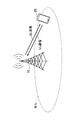
- FIG. 1 is a diagram showing a configuration example of a wireless communication system according to the embodiment of the present invention.
- the wireless communication system according to the embodiment of the present invention includes a base station 10 and a terminal 20 as shown in FIG.
- FIG. 1 shows one base station 10 and one terminal 20, this is an example, and there may be a plurality of each.
- the base station 10 is a communication device that provides one or more cells and performs wireless communication with the terminal 20.
- the physical resources of the radio signal are defined in the time domain and the frequency domain, the time domain may be defined by the number of OFDM (Orthogonal Frequency Division Multiplexing) symbols, and the frequency domain is defined by the number of subcarriers or the number of resource blocks. May be good.
- the base station 10 transmits a synchronization signal and system information to the terminal 20. Synchronous signals are, for example, NR-PSS and NR-SSS.
- the system information is transmitted by, for example, NR-PBCH, and is also referred to as broadcast information.
- the synchronization signal and system information may be referred to as SSB (SS / PBCH block).
- the base station 10 transmits a control signal or data to the terminal 20 by DL (Downlink), and receives the control signal or data from the terminal 20 by UL (Uplink). Both the base station 10 and the terminal 20 can perform beamforming to transmit and receive signals. Further, both the base station 10 and the terminal 20 can apply MIMO (Multiple Input Multiple Output) communication to DL or UL. Further, both the base station 10 and the terminal 20 may communicate via a secondary cell (SCell: Secondary Cell) and a primary cell (PCell: Primary Cell) by CA (Carrier Aggregation). Further, the terminal 20 may perform communication via a primary cell of the base station 10 by DC (Dual Connectivity) and a primary secondary cell (PSCell: Primary Secondary Cell) of another base station 10.
- SCell Secondary Cell
- PCell Primary Cell
- CA Carrier Aggregation
- the terminal 20 is a communication device having a wireless communication function such as a smartphone, a mobile phone, a tablet, a wearable terminal, and a communication module for M2M (Machine-to-Machine). As shown in FIG. 1, the terminal 20 receives a control signal or data from the base station 10 on the DL and transmits the control signal or data to the base station 10 on the UL, thereby providing various types provided by the wireless communication system. Use communication services. Further, the terminal 20 receives various reference signals transmitted from the base station 10 and executes the measurement of the propagation path quality based on the reception result of the reference signals.
- M2M Machine-to-Machine
- NR-based IoT devices (hereinafter, also referred to as “NR-IoT”) are considered as NR devices with reduced complexity.
- NR-IoT may have the characteristics shown in 1) -5) below.
- NR-BL bandwidth reduced low complexity
- NR-IoT may be replaceable.
- the bandwidth of the eMTC-UE was limited to 6PRB (Physical resource block). Since the SS / MIB (Master information block) is transmitted at 6 PRB at the center frequency position of the LTE carrier, the eMTC-UE was able to reuse the SS / MIB.
- the SIB1-BR is system information defined only in the BL-UE, and the MIB 1-BR is notified of the scheduling information of the SIB1-BR.
- the reduction of the bandwidth and the reduction of the number of transmitting / receiving antennas are indispensable elements also in the NR-IoT device.
- bandwidth is reduced, some channels or signals may need to be modified.
- support for enhanced coverage may be required for some channels or signals as well as eMTC.
- the NR-BL-UE needs to support a bandwidth of 20 PRB or more when using an existing SSB.
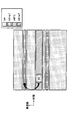
- FIG. 2 is a diagram showing an example of resource allocation.
- resources may be allocated to each system or RAT (eg, NR, eMTC, NB-IoT), for example, as shown in FIG.
- a resource reservation mechanism may be supported in each system or RAT to achieve efficient coexistence. For example, as shown in FIG. 2, for resources in which NR-SSB and eMTC overlap, resource reservation in the time domain may be made by the eMTC side in order to avoid collision. That is, the eMTC-UE does not have to use the resources occupied by the NR-SSB. Further, the frequency domain occupied by the eMTC may be reserved according to the NR specifications.
- Each system or RAT may be generically referred to as a system.
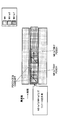
- FIG. 3 is a diagram showing an example of arranging resources used for initial access.
- NR For the initial access of NR, for example, it is necessary to receive PDCCH by SSB, CORESET # 0 and PDSCH to which SIB1 for NR-non-BL-UE is transmitted.
- the NR-BL-UE is a UE that cannot support 20 PRB, the SSB cannot be monitored. In that case, all NR channels or signals will need to be redesigned for that NR-BL-UE.
- the NR-BL-UE may not be able to monitor the NR-SSB.
- DL and / or UL traffic generated in IoT applications is very small compared to high-end devices and the like, so if multiple IoT systems (eMTC, NB-IoT, NR-IoT) coexist, the utilization efficiency of wireless resources May decrease.
- the NR-IoT may share resources in the time domain and / or frequency domain of another system or RAT. Some channels or signals defined by other systems or RATs may be shared by the NR-IoT and other systems or RATs.
- FIG. 4 is a diagram showing an example (1) of resource arrangement according to the embodiment of the present invention.
- resources may be shared between NR-IoT and NB-IoT.
- the NR-IoT device may use NPSS / NSSS (Narrowband PSS / Narrowband SSS) in NB-IoT as a synchronization signal.
- NPSS / NSSS Narrowband PSS / Narrowband SSS
- CRS Cell specific reference signal
- other shared channels or signals may be shared by NR-IoT and NB-IoT.
- FIG. 5 is a diagram showing an example (2) of resource arrangement according to the embodiment of the present invention.
- the resources in a part of the time domain of NR-IoT may be the same as the frequency domain of NB-IoT.
- the NR-IoT device may use NPSS / NSSS in NB-IoT as a synchronization signal.
- CRS and other shared channels or signals may be shared by NR-IoT and NB-IoT.
- FIG. 6 is a diagram showing an example (3) of resource arrangement according to the embodiment of the present invention.
- the NR-IoT device may use NPSS / NSSS in NB-IoT as a synchronization signal.
- the frequency domain of the resource may be set individually for NR-IoT and NB-IoT.
- FIG. 7 is a diagram showing an example (4) of resource arrangement according to the embodiment of the present invention.
- the sync signal defined for the legacy UE may be reused for the NR-BL-UE.
- the sequence used for all or part of the synchronization signals contained in the SSB may be defined as the SS sequence for the NR-BL-UE.
- the SS sequence of NB-IoT that is, the sequence applied to NPSS / NSSS may be reused as a sequence of synchronization signals for NR-BL-UE.
- the NR-BL-UE may apply the SCS of 30 kHz, and may further monitor the PSS / SSS to which the SCS of 15 kHz is applied.
- FIG. 8 is a flowchart for explaining an operation example (1) of NR-IoT according to the embodiment of the present invention.
- the initial access of the NR-IoT device will be described with reference to FIG.
- the terminal 20 starts access in NR-IoT.
- the terminal 20 executes synchronization in NR-IoT using the synchronization signal for NB-IoT (S12).
- the terminal 20 starts communication in NR-IoT (S13).
- the synchronization signal for NB-IoT in step S12 may be replaced with the SS sequence for NB-IoT.
- FIG. 9 is a diagram showing an example (5) of resource arrangement according to the embodiment of the present invention.
- the sync signal defined for the legacy UE may be reused for the NR-BL-UE.
- the SS sequence of eMTC that is, the sequence applied to PSS / SSS
- the NR-BL-UE may apply the SCS of 30 kHz, and may further monitor the PSS / SSS to which the SCS of 15 kHz is applied.
- FIG. 10 is a flowchart for explaining an operation example (2) of NR-IoT according to the embodiment of the present invention.
- the initial access of the NR-IoT device will be described with reference to FIG.
- the terminal 20 starts the access in NR-IoT.
- the terminal 20 executes synchronization in NR-IoT using the synchronization signal for eMTC (S22).
- the terminal 20 starts communication in NR-IoT (S23).
- the synchronization signal for eMTC in step S22 may be replaced with the SS sequence for eMTC.
- the NR-BL-UE may have the ability to monitor a plurality of SSs.
- the NR-BL-UE has the ability to simultaneously monitor any two or three combinations of PSS / SSS for eMTC, NPSS / NSSS for NB-IoT, and NR-SSB. You may.
- FIG. 11 is a diagram showing an example (6) of resource arrangement according to the embodiment of the present invention.
- PDCCH Physical Downlink Control Channel
- some or all of the PDCCH (or CORESET) resources are NR-IoT and NB, as shown in FIG. - May be shared with IoT.
- different PDCCH formats may be used for NR-IoT and NB-IoT.
- the same DCI format may be defined, and the DCI format may notify which system the DCI is for.
- different RNTIs may be used for NR-IoT and NB-IoT in the search space of the PDCCH resource.
- the signaling from the base station 10 to the terminal 20 or the signaling from the terminal 20 to the base station 10 in the above-described embodiment is not limited to an explicit method, and may be notified by an implicit method. good. In addition, signaling is not performed and may be uniquely specified in the specifications.
- the signaling from the base station 10 to the terminal 20 or the signaling from the terminal 20 to the base station 10 in the above-described embodiment may be different layers of signaling such as RRC signaling, MAC-CE signaling, or DCI signaling.
- Signaling by broadcast information MIB (Master Information Block), SIB (System Information Block)
- MIB Master Information Block
- SIB System Information Block
- RRC signaling and DCI signaling may be combined, RRC signaling and MAC-CE signaling may be combined, or RRC signaling, MAC-CE signaling, and DCI signaling may be combined.
- the terminal 20 shares radio resources or signals with other systems or other RAT devices when operating as an NR-based IoT device, even if the NR-SSB cannot be monitored. Allows initial access to be performed.
- the resource utilization efficiency can be improved.
- the base station 10 and the terminal 20 include a function of carrying out the above-described embodiment.
- the base station 10 and the terminal 20 may each have only a part of the functions in the embodiment.
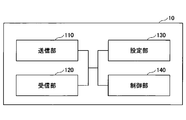
- FIG. 12 is a diagram showing an example of the functional configuration of the base station 10 according to the embodiment of the present invention.
- the base station 10 includes a transmission unit 110, a reception unit 120, a setting unit 130, and a control unit 140.
- the functional configuration shown in FIG. 12 is only an example. Any function classification and name of the functional unit may be used as long as the operation according to the embodiment of the present invention can be executed.
- the transmission unit 110 includes a function of generating a signal to be transmitted to the terminal 20 side and transmitting the signal wirelessly. Further, the transmission unit 110 transmits a message between network nodes to another network node.
- the receiving unit 120 includes a function of receiving various signals transmitted from the terminal 20 and acquiring information of, for example, a higher layer from the received signals. Further, the transmission unit 110 has a function of transmitting NR-PSS, NR-SSS, NR-PBCH, DL / UL control signal and the like to the terminal 20. In addition, the receiving unit 120 receives a message between network nodes from another network node.
- the setting unit 130 stores preset setting information and various setting information to be transmitted to the terminal 20.
- the content of the setting information is, for example, information related to the setting of NR-IoT.
- the control unit 140 controls the setting of the NR-IoT as described in the embodiment. In addition, the control unit 140 controls communication by NR-IoT.
- the function unit related to signal transmission in the control unit 140 may be included in the transmission unit 110, and the function unit related to signal reception in the control unit 140 may be included in the reception unit 120.
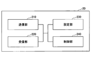
- FIG. 13 is a diagram showing an example of the functional configuration of the terminal 20 according to the embodiment of the present invention.
- the terminal 20 has a transmission unit 210, a reception unit 220, a setting unit 230, and a control unit 240.
- the functional configuration shown in FIG. 13 is only an example. Any function classification and name of the functional unit may be used as long as the operation according to the embodiment of the present invention can be executed.
- the transmission unit 210 creates a transmission signal from the transmission data and wirelessly transmits the transmission signal.
- the receiving unit 220 wirelessly receives various signals and acquires a signal of a higher layer from the received signal of the physical layer. Further, the receiving unit 220 has a function of receiving NR-PSS, NR-SSS, NR-PBCH, DL / UL / SL control signals and the like transmitted from the base station 10. Further, for example, the transmission unit 210 connects the other terminal 20 to PSCCH (Physical Sidelink Control Channel), PSCH (Physical Sidelink Shared Channel), PSDCH (Physical Sidelink Discovery Channel), PSBCH (Physical Sidelink Broadcast Channel) as D2D communication. Etc., and the receiving unit 220 receives the PSCCH, PSCH, PSDCH, PSBCH, etc. from the other terminal 20.
- PSCCH Physical Sidelink Control Channel
- PSCH Physical Sidelink Shared Channel
- PSDCH Physical Sidelink Discovery Channel
- PSBCH Physical Sidelink Broadcast
- the setting unit 230 stores various setting information received from the base station 10 by the receiving unit 220.
- the setting unit 230 also stores preset setting information.
- the content of the setting information is, for example, information related to the setting of NR-IoT.
- the control unit 240 controls the setting of the NR-IoT as described in the embodiment. Further, the control unit 240 controls the communication by NR-IoT.
- the function unit related to signal transmission in the control unit 240 may be included in the transmission unit 210, and the function unit related to signal reception in the control unit 240 may be included in the reception unit 220.
- each functional block may be realized by using one physically or logically connected device, or directly or indirectly (for example, two or more physically or logically separated devices). , Wired, wireless, etc.) and may be realized using these plurality of devices.
- the functional block may be realized by combining the software with the one device or the plurality of devices.
- Functions include judgment, decision, judgment, calculation, calculation, processing, derivation, investigation, search, confirmation, reception, transmission, output, access, solution, selection, selection, establishment, comparison, assumption, expectation, and assumption. Broadcasting, notifying, communicating, forwarding, configuring, reconfiguring, allocating, mapping, assigning, etc., but limited to these I can't.
- a functional block that makes transmission function is called a transmitting unit (transmitting unit) or a transmitter (transmitter).
- transmitting unit transmitting unit
- transmitter transmitter
- the base station 10, the terminal 20, and the like in one embodiment of the present disclosure may function as a computer that processes the wireless communication method of the present disclosure.
- FIG. 14 is a diagram showing an example of the hardware configuration of the base station 10 and the terminal 20 according to the embodiment of the present disclosure.
- the above-mentioned base station 10 and terminal 20 are physically configured as a computer device including a processor 1001, a storage device 1002, an auxiliary storage device 1003, a communication device 1004, an input device 1005, an output device 1006, a bus 1007, and the like. May be good.
- the word “device” can be read as a circuit, device, unit, etc.
- the hardware configuration of the base station 10 and the terminal 20 may be configured to include one or more of the devices shown in the figure, or may be configured not to include some of the devices.
- the processor 1001 For each function of the base station 10 and the terminal 20, the processor 1001 performs an operation by loading predetermined software (program) on the hardware such as the processor 1001 and the storage device 1002, and controls the communication by the communication device 1004. It is realized by controlling at least one of reading and writing of data in the storage device 1002 and the auxiliary storage device 1003.
- Processor 1001 operates, for example, an operating system to control the entire computer.
- the processor 1001 may be composed of a central processing unit (CPU: Central Processing Unit) including an interface with a peripheral device, a control device, an arithmetic unit, a register, and the like.
- CPU Central Processing Unit
- control unit 140, control unit 240, and the like may be realized by the processor 1001.
- the processor 1001 reads a program (program code), a software module, data, or the like from at least one of the auxiliary storage device 1003 and the communication device 1004 into the storage device 1002, and executes various processes according to these.
- a program program that causes a computer to execute at least a part of the operations described in the above-described embodiment is used.
- the control unit 140 of the base station 10 shown in FIG. 12 may be realized by a control program stored in the storage device 1002 and operated by the processor 1001.
- the control unit 240 of the terminal 20 shown in FIG. 13 may be realized by a control program stored in the storage device 1002 and operated by the processor 1001.
- Processor 1001 may be implemented by one or more chips.
- the program may be transmitted from the network via a telecommunication line.
- the storage device 1002 is a computer-readable recording medium, for example, by at least one of ROM (Read Only Memory), EPROM (Erasable Programmable ROM), EEPROM (Electrically Erasable Programmable ROM), RAM (Random Access Memory), and the like. It may be configured.
- the storage device 1002 may be referred to as a register, a cache, a main memory (main storage device), or the like.
- the storage device 1002 can store a program (program code), a software module, or the like that can be executed to implement the communication method according to the embodiment of the present disclosure.
- the auxiliary storage device 1003 is a computer-readable recording medium, and is, for example, an optical disk such as a CD-ROM (Compact Disc ROM), a hard disk drive, a flexible disk, an optical magnetic disk (for example, a compact disk, a digital versatile disk, Blu).
- -It may be composed of at least one of a ray (registered trademark) disk), a smart card, a flash memory (for example, a card, a stick, a key drive), a floppy (registered trademark) disk, a magnetic strip, and the like.
- the storage medium described above may be, for example, a database, server or other suitable medium containing at least one of the storage device 1002 and the auxiliary storage device 1003.
- the communication device 1004 is hardware (transmission / reception device) for communicating between computers via at least one of a wired network and a wireless network, and is also referred to as, for example, a network device, a network controller, a network card, a communication module, or the like.
- the communication device 1004 includes, for example, a high frequency switch, a duplexer, a filter, a frequency synthesizer, and the like in order to realize at least one of frequency division duplex (FDD: Frequency Division Duplex) and time division duplex (TDD: Time Division Duplex). It may be composed of.
- FDD Frequency Division Duplex
- TDD Time Division Duplex
- the transmission / reception unit may be physically or logically separated from each other in the transmission unit and the reception unit.
- the input device 1005 is an input device (for example, a keyboard, a mouse, a microphone, a switch, a button, a sensor, etc.) that receives an input from the outside.
- the output device 1006 is an output device (for example, a display, a speaker, an LED lamp, etc.) that outputs to the outside.
- the input device 1005 and the output device 1006 may have an integrated configuration (for example, a touch panel).
- each device such as the processor 1001 and the storage device 1002 is connected by a bus 1007 for communicating information.
- the bus 1007 may be configured by using a single bus, or may be configured by using a different bus for each device.
- the base station 10 and the terminal 20 are hardware such as a microprocessor, a digital signal processor (DSP: Digital Signal Processor), an ASIC (Application Specific Integrated Circuit), a PLD (Programmable Logic Device), and an FPGA (Field Programmable Gate Array). It may be configured to include, and a part or all of each functional block may be realized by the hardware. For example, processor 1001 may be implemented using at least one of these hardware.
- DSP Digital Signal Processor
- ASIC Application Specific Integrated Circuit
- PLD Programmable Logic Device
- FPGA Field Programmable Gate Array
- control unit that shares a part of the resources of the time domain or the part of the frequency domain with the first system and the shared resources are used.
- a terminal having a communication unit that performs communication in the second system is provided.
- the terminal 20 can operate as an NR-based IoT device by sharing radio resources or signals with other systems or other RAT devices, even if the NR-SSB cannot be monitored. , Can perform initial access. That is, in the wireless communication system, the efficiency of resource utilization can be improved.
- the control unit executes synchronization in the second system based on the synchronization signal of the first system, and executes synchronization in the second system based on the synchronization signal of the second system. You do not have to have the ability.
- the terminal 20 can operate as an NR-based IoT device by sharing radio resources or signals with other systems or other RAT devices, even if the NR-SSB cannot be monitored. Initial access can be performed.
- the control unit may execute synchronization in the second system based on a sequence applied to the synchronization signal of the first system.
- the terminal 20 can improve the utilization efficiency of resources by sharing resources with other systems.
- the resource in which the control signal of the second system is arranged and the resource in which the control signal of the first system is arranged may be shared.
- the terminal 20 can improve the utilization efficiency of resources by sharing resources with other systems.
- the first system may be NB (Narrowband) -IoT (Internet of Things) or eMTC (enhanced Machine type communication), and the second system may be NR (New Radio) -IoT.
- NB Narrowband
- eMTC enhanced Machine type communication
- NR New Radio
- the terminal 20 can operate as an NR-based IoT device by sharing radio resources or signals with other systems or other RAT devices, even if the NR-SSB cannot be monitored. Initial access can be performed.
- control procedure for sharing a resource of a part of the time domain or a part of the frequency domain with the first system and the shared resource are used in the second system.
- a communication method is provided in which the terminal executes the communication procedure for communicating.
- the terminal 20 can operate as an NR-based IoT device by sharing radio resources or signals with other systems or other RAT devices, even if the NR-SSB cannot be monitored. , Can perform initial access. That is, in the wireless communication system, the efficiency of resource utilization can be improved.
- the operation of the plurality of functional units may be physically performed by one component, or the operation of one functional unit may be physically performed by a plurality of components.
- the processing order may be changed as long as there is no contradiction.
- the base station 10 and the terminal 20 have been described with reference to functional block diagrams, but such devices may be implemented in hardware, software, or a combination thereof.
- the software operated by the processor of the base station 10 according to the embodiment of the present invention and the software operated by the processor of the terminal 20 according to the embodiment of the present invention are random access memory (RAM), flash memory, and read-only memory, respectively. It may be stored in (ROM), EPROM, EEPROM, registers, hard disk (HDD), removable disk, CD-ROM, database, server or any other suitable storage medium.
- information notification includes physical layer signaling (for example, DCI (Downlink Control Information), UCI (Uplink Control Information)), higher layer signaling (for example, RRC (Radio Resource Control) signaling, MAC (Medium Access Control) signaling, etc. Broadcast information (MIB (Master Information Block), SIB (System Information Block)), other signals, or a combination thereof may be used.
- RRC signaling may be referred to as an RRC message, for example, RRC. It may be a connection setup (RRCConnectionSetup) message, an RRC connection reconfiguration (RRCConnectionReconfiguration) message, or the like.
- Each aspect / embodiment described in the present disclosure includes LTE (Long Term Evolution), LTE-A (LTE-Advanced), SUPER 3G, IMT-Advanced, 4G (4th generation mobile communication system), and 5G (5th generation mobile communication).
- system FRA (Future Radio Access), NR (new Radio), W-CDMA (registered trademark), GSM (registered trademark), CDMA2000, UMB (Ultra Mobile Broadband), IEEE 802.11 (Wi-Fi (registered trademark)) )), LTE 802.16 (WiMAX®), IEEE 802.20, UWB (Ultra-WideBand), Bluetooth®, and other systems that utilize suitable systems and have been extended based on these. It may be applied to at least one of the next generation systems. Further, a plurality of systems may be applied in combination (for example, a combination of at least one of LTE and LTE-A and 5G).
- the specific operation performed by the base station 10 in the present specification may be performed by its upper node.
- various operations performed for communication with the terminal 20 are performed by the base station 10 and other network nodes other than the base station 10 (for example, it is clear that it can be done by at least one of (but not limited to, MME, S-GW, etc.).
- the other network node may be a combination of a plurality of other network nodes (for example, MME and S-GW). ..
- the information, signals, etc. described in the present disclosure can be output from the upper layer (or lower layer) to the lower layer (or upper layer). Input / output may be performed via a plurality of network nodes.
- the input / output information and the like may be stored in a specific location (for example, memory) or may be managed using a management table. Input / output information and the like can be overwritten, updated, or added. The output information and the like may be deleted. The input information or the like may be transmitted to another device.
- the determination in the present disclosure may be made by a value represented by 1 bit (0 or 1), by a true / false value (Boolean: true or false), or by comparing numerical values (for example,). , Comparison with a predetermined value).
- Software whether referred to as software, firmware, middleware, microcode, hardware description language, or other names, is an instruction, instruction set, code, code segment, program code, program, subprogram, software module.
- Applications, software applications, software packages, routines, subroutines, objects, executable files, execution threads, procedures, functions, etc. should be broadly interpreted.
- software, instructions, information, etc. may be transmitted and received via a transmission medium.
- the software uses at least one of wired technology (coaxial cable, optical fiber cable, twisted pair, digital subscriber line (DSL: Digital Subscriber Line), etc.) and wireless technology (infrared, microwave, etc.) to create a website.
- wired technology coaxial cable, optical fiber cable, twisted pair, digital subscriber line (DSL: Digital Subscriber Line), etc.
- wireless technology infrared, microwave, etc.
- the information, signals, etc. described in this disclosure may be represented using any of a variety of different techniques.
- data, instructions, commands, information, signals, bits, symbols, chips, etc. that may be referred to throughout the above description are voltages, currents, electromagnetic waves, magnetic fields or magnetic particles, light fields or photons, or any of these. It may be represented by a combination of.
- a channel and a symbol may be a signal (signaling).
- the signal may be a message.
- the component carrier CC: Component Carrier
- CC Component Carrier
- system and “network” used in this disclosure are used interchangeably.
- the information, parameters, etc. described in the present disclosure may be expressed using absolute values, relative values from predetermined values, or using other corresponding information. It may be represented.
- the radio resource may be one indicated by an index.
- base station Base Station
- wireless base station base station
- base station device fixed station
- NodeB nodeB
- eNodeB eNodeB
- GNB nodeB
- access point “ transmission point ”,“ reception point ”,“ transmission / reception point ”,“ cell ”,“ sector ”
- Terms such as “cell group,” “carrier,” and “component carrier” can be used interchangeably.
- Base stations are sometimes referred to by terms such as macrocells, small cells, femtocells, and picocells.
- the base station can accommodate one or more (for example, three) cells.
- a base station accommodates multiple cells, the entire coverage area of the base station can be divided into multiple smaller areas, each smaller area being a base station subsystem (eg, a small indoor base station (RRH:)).
- Communication services can also be provided by Remote Radio Head).
- the term "cell” or “sector” refers to part or all of the coverage area of at least one of the base stations and base station subsystems that provide communication services in this coverage. Point to.
- MS Mobile Station
- UE User Equipment
- Mobile stations can be used by those skilled in the art as subscriber stations, mobile units, subscriber units, wireless units, remote units, mobile devices, wireless devices, wireless communication devices, remote devices, mobile subscriber stations, access terminals, mobile terminals, wireless. It may also be referred to as a terminal, remote terminal, handset, user agent, mobile client, client, or some other suitable term.
- At least one of the base station and the mobile station may be called a transmitting device, a receiving device, a communication device, or the like. At least one of the base station and the mobile station may be a device mounted on the mobile body, the mobile body itself, or the like.
- the moving body may be a vehicle (for example, a car, an airplane, etc.), an unmanned moving body (for example, a drone, an autonomous vehicle, etc.), or a robot (manned or unmanned type). ) May be.
- at least one of the base station and the mobile station includes a device that does not necessarily move during communication operation.
- at least one of the base station and the mobile station may be an IoT (Internet of Things) device such as a sensor.
- IoT Internet of Things
- the base station in the present disclosure may be read by the user terminal.
- the communication between the base station and the user terminal is replaced with the communication between a plurality of terminals 20 (for example, it may be called D2D (Device-to-Device), V2X (Vehicle-to-Everything), etc.).
- D2D Device-to-Device
- V2X Vehicle-to-Everything
- Each aspect / embodiment of the present disclosure may be applied to the configuration.
- the terminal 20 may have the function of the base station 10 described above.
- words such as "up” and “down” may be read as words corresponding to communication between terminals (for example, "side”).
- the upstream channel, the downstream channel, and the like may be read as a side channel.
- the user terminal in the present disclosure may be read as a base station.
- the base station may have the functions of the user terminal described above.
- determining and “determining” used in this disclosure may include a wide variety of actions.
- “Judgment” and “decision” are, for example, judgment (judging), calculation (calculating), calculation (computing), processing (processing), derivation (deriving), investigation (investigating), search (looking up, search, inquiry). (For example, searching in a table, database or another data structure), ascertaining may be regarded as “judgment” or “decision”.
- judgment and “decision” are receiving (for example, receiving information), transmitting (for example, transmitting information), input (input), output (output), and access.
- Accessing (for example, accessing data in memory) may be regarded as "judgment” or “decision”.
- judgment and “decision” mean that the things such as solving, selecting, choosing, establishing, and comparing are regarded as “judgment” and “decision”. Can include. That is, “judgment” and “decision” may include considering some action as “judgment” and “decision”. Further, “judgment (decision)” may be read as “assuming”, “expecting”, “considering” and the like.
- connection means any direct or indirect connection or connection between two or more elements, and each other. It can include the presence of one or more intermediate elements between two “connected” or “combined” elements.
- the connections or connections between the elements may be physical, logical, or a combination thereof.
- connection may be read as "access”.
- the two elements use at least one of one or more wires, cables and printed electrical connections, and, as some non-limiting and non-comprehensive examples, the radio frequency domain. Can be considered to be “connected” or “coupled” to each other using electromagnetic energy having wavelengths in the microwave and light (both visible and invisible) regions.
- the reference signal can also be abbreviated as RS (Reference Signal), and may be called a pilot (Pilot) depending on the applicable standard.
- RS Reference Signal
- Pilot Pilot
- references to elements using designations such as “first” and “second” as used in this disclosure does not generally limit the quantity or order of those elements. These designations can be used in the present disclosure as a convenient way to distinguish between two or more elements. Thus, references to the first and second elements do not mean that only two elements can be adopted, or that the first element must somehow precede the second element.
- the wireless frame may be composed of one or more frames in the time domain. Each one or more frames in the time domain may be referred to as a subframe. Subframes may further consist of one or more slots in the time domain.
- the subframe may have a fixed time length (eg, 1 ms) that does not depend on numerology.
- the numerology may be a communication parameter that applies to at least one of the transmission and reception of a signal or channel.
- Numerology includes, for example, subcarrier spacing (SCS: SubCarrier Spacing), bandwidth, symbol length, cyclic prefix length, transmission time interval (TTI: Transmission Time Interval), number of symbols per TTI, wireless frame configuration, and transmitter / receiver.
- SCS subcarrier spacing
- TTI Transmission Time Interval
- At least one of a specific filtering process performed in the frequency domain, a specific windowing process performed by the transmitter / receiver in the time domain, and the like may be indicated.
- the slot may be composed of one or more symbols in the time domain (OFDM (Orthogonal Frequency Division Multiplexing) symbol, SC-FDMA (Single Carrier Frequency Division Multiple Access) symbol, etc.). Slots may be in time units based on New Melology.
- OFDM Orthogonal Frequency Division Multiplexing
- SC-FDMA Single Carrier Frequency Division Multiple Access
- the slot may include a plurality of mini slots. Each minislot may consist of one or more symbols in the time domain.
- the mini-slot may also be referred to as a sub-slot.
- a minislot may consist of a smaller number of symbols than the slot.
- a PDSCH (or PUSCH) transmitted in a time unit larger than the minislot may be referred to as a PDSCH (or PUSCH) mapping type A.
- the PDSCH (or PUSCH) transmitted using the minislot may be referred to as PDSCH (or PUSCH) mapping type B.
- the wireless frame, subframe, slot, minislot and symbol all represent the time unit when transmitting a signal.
- the radio frame, subframe, slot, minislot and symbol may have different names corresponding to each.
- one subframe may be called a transmission time interval (TTI), a plurality of consecutive subframes may be called TTI, and one slot or one minislot may be called TTI.
- TTI transmission time interval
- the unit representing TTI may be called a slot, a mini slot, or the like instead of a subframe.
- TTI refers to, for example, the minimum time unit of scheduling in wireless communication.
- the base station schedules each terminal 20 to allocate radio resources (frequency bandwidth that can be used in each terminal 20, transmission power, etc.) in TTI units.
- the definition of TTI is not limited to this.
- the TTI may be a transmission time unit such as a channel-encoded data packet (transport block), a code block, or a code word, or may be a processing unit such as scheduling or link adaptation.
- the time interval for example, the number of symbols
- the transport block, code block, code word, etc. may be shorter than the TTI.
- one or more TTIs may be the minimum time unit for scheduling. Further, the number of slots (number of mini-slots) constituting the minimum time unit of the scheduling may be controlled.
- a TTI having a time length of 1 ms may be referred to as a normal TTI (TTI in LTE Rel. 8-12), a normal TTI, a long TTI, a normal subframe, a normal subframe, a long subframe, a slot, or the like.
- TTIs shorter than normal TTIs may be referred to as shortened TTIs, short TTIs, partial TTIs (partial or fractional TTIs), shortened subframes, short subframes, minislots, subslots, slots, and the like.
- the long TTI (for example, normal TTI, subframe, etc.) may be read as a TTI having a time length of more than 1 ms, and the short TTI (for example, shortened TTI, etc.) is less than the TTI length of the long TTI and 1 ms. It may be read as a TTI having the above TTI length.
- the resource block (RB) is a resource allocation unit in the time domain and the frequency domain, and may include one or a plurality of continuous subcarriers in the frequency domain.
- the number of subcarriers contained in the RB may be the same regardless of the numerology, and may be, for example, 12.
- the number of subcarriers contained in the RB may be determined based on numerology.
- the time domain of RB may include one or more symbols, and may have a length of 1 slot, 1 mini slot, 1 subframe, or 1 TTI.
- Each 1TTI, 1 subframe, etc. may be composed of one or a plurality of resource blocks.
- One or more RBs include a physical resource block (PRB: Physical RB), a sub-carrier group (SCG: Sub-Carrier Group), a resource element group (REG: Resource Element Group), a PRB pair, an RB pair, and the like. May be called.
- PRB Physical resource block
- SCG Sub-Carrier Group
- REG Resource Element Group
- PRB pair an RB pair, and the like. May be called.
- the resource block may be composed of one or a plurality of resource elements (RE: Resource Element).
- RE Resource Element
- 1RE may be a radio resource area of 1 subcarrier and 1 symbol.
- Bandwidth part (which may also be called partial bandwidth) may represent a subset of consecutive common resource blocks (RBs) for a certain neurology in a carrier.
- the common RB may be specified by the index of the RB with respect to the common reference point of the carrier.
- PRBs may be defined in a BWP and numbered within that BWP.
- the BWP may include a BWP for UL (UL BWP) and a BWP for DL (DL BWP).
- UL BWP UL BWP
- DL BWP DL BWP
- One or more BWPs may be set in one carrier for the UE.
- At least one of the configured BWPs may be active, and the UE may not expect to send or receive a given signal / channel outside the active BWP.
- “cell”, “carrier” and the like in this disclosure may be read as “BWP”.
- the above-mentioned structures such as wireless frames, subframes, slots, minislots and symbols are merely examples.
- the number of subframes contained in a wireless frame the number of slots per subframe or wireless frame, the number of minislots contained within a slot, the number of symbols and RBs contained in a slot or minislot, included in the RB.
- the number of subcarriers, the number of symbols in the TTI, the symbol length, the cyclic prefix (CP) length, and the like can be changed in various ways.
- the term "A and B are different” may mean “A and B are different from each other”.
- the term may mean that "A and B are different from C”.
- Terms such as “separate” and “combined” may be interpreted in the same way as “different”.
- the notification of predetermined information (for example, the notification of "being X") is not limited to the explicit one, but is performed implicitly (for example, the notification of the predetermined information is not performed). May be good.
- the transmitting unit 210 and the receiving unit 220 in the present disclosure are examples of communication units.
- Base station 110 Transmission unit 120 Reception unit 130 Setting unit 140 Control unit 20 Terminal 210 Transmission unit 220 Reception unit 230 Setting unit 240 Control unit 1001 Processor 1002 Storage device 1003 Auxiliary storage device 1004 Communication device 1005 Input device 1006 Output device
Landscapes
- Engineering & Computer Science (AREA)
- Signal Processing (AREA)
- Computer Networks & Wireless Communication (AREA)
- Mobile Radio Communication Systems (AREA)
Abstract
Un terminal comprend : une unité de commande qui partage une partie de ressources de domaine temporel ou une partie de ressources de domaine fréquentiel avec un premier système; et une unité de communication qui utilise les ressources partagées pour effectuer une communication dans un second système.
Priority Applications (2)
| Application Number | Priority Date | Filing Date | Title |
|---|---|---|---|
| PCT/JP2020/017266 WO2021214894A1 (fr) | 2020-04-21 | 2020-04-21 | Terminal et procédé de communication |
| EP20932363.3A EP4142333A4 (fr) | 2020-04-21 | 2020-04-21 | Terminal et procédé de communication |
Applications Claiming Priority (1)
| Application Number | Priority Date | Filing Date | Title |
|---|---|---|---|
| PCT/JP2020/017266 WO2021214894A1 (fr) | 2020-04-21 | 2020-04-21 | Terminal et procédé de communication |
Publications (1)
| Publication Number | Publication Date |
|---|---|
| WO2021214894A1 true WO2021214894A1 (fr) | 2021-10-28 |
Family
ID=78270553
Family Applications (1)
| Application Number | Title | Priority Date | Filing Date |
|---|---|---|---|
| PCT/JP2020/017266 WO2021214894A1 (fr) | 2020-04-21 | 2020-04-21 | Terminal et procédé de communication |
Country Status (2)
| Country | Link |
|---|---|
| EP (1) | EP4142333A4 (fr) |
| WO (1) | WO2021214894A1 (fr) |
Citations (2)
| Publication number | Priority date | Publication date | Assignee | Title |
|---|---|---|---|---|
| JP2010136326A (ja) * | 2008-11-04 | 2010-06-17 | Ntt Docomo Inc | 無線基地局装置及び移動端末装置 |
| WO2017038741A1 (fr) * | 2015-09-01 | 2017-03-09 | 株式会社Nttドコモ | Terminal utilisateur, station de base sans fil et procédé de communication sans fil |
Family Cites Families (2)
| Publication number | Priority date | Publication date | Assignee | Title |
|---|---|---|---|---|
| EP3813445A4 (fr) * | 2018-05-23 | 2022-03-02 | NTT DoCoMo, Inc. | Terminal utilisateur et procédé de communication sans fil |
| US11902879B2 (en) * | 2018-08-02 | 2024-02-13 | Nokia Technologies Oy | Method for standalone MTC operation |
-
2020
- 2020-04-21 WO PCT/JP2020/017266 patent/WO2021214894A1/fr unknown
- 2020-04-21 EP EP20932363.3A patent/EP4142333A4/fr active Pending
Patent Citations (2)
| Publication number | Priority date | Publication date | Assignee | Title |
|---|---|---|---|---|
| JP2010136326A (ja) * | 2008-11-04 | 2010-06-17 | Ntt Docomo Inc | 無線基地局装置及び移動端末装置 |
| WO2017038741A1 (fr) * | 2015-09-01 | 2017-03-09 | 株式会社Nttドコモ | Terminal utilisateur, station de base sans fil et procédé de communication sans fil |
Non-Patent Citations (4)
| Title |
|---|
| 3GPP TS 36.211, January 2020 (2020-01-01) |
| 3GPP TS 38.300, December 2019 (2019-12-01) |
| NTT DOCOMO INC.: "Views on Release 17", 3GPP DRAFT; RP-191419_VIEWS ON RELEASE 17 DOCOMO, 3RD GENERATION PARTNERSHIP PROJECT (3GPP), MOBILE COMPETENCE CENTRE ; 650, ROUTE DES LUCIOLES ; F-06921 SOPHIA-ANTIPOLIS CEDEX ; FRANCE, vol. TSG RAN, 31 May 2019 (2019-05-31), Mobile Competence Centre ; 650, route des Lucioles ; F-06921 Sophia-Antipolis Cedex ; France , XP051739834 * |
| See also references of EP4142333A4 |
Also Published As
| Publication number | Publication date |
|---|---|
| EP4142333A1 (fr) | 2023-03-01 |
| EP4142333A4 (fr) | 2024-01-10 |
Similar Documents
| Publication | Publication Date | Title |
|---|---|---|
| WO2020194760A1 (fr) | Dispositif utilisateur et dispositif de station de base | |
| WO2020230201A1 (fr) | Dispositif utilisateur et dispositif de station de base | |
| JPWO2020170405A1 (ja) | ユーザ装置及び基地局装置 | |
| WO2020235318A1 (fr) | Équipement utilisateur et dispositif de station de base | |
| WO2021199415A1 (fr) | Terminal et procédé de communication | |
| WO2021149246A1 (fr) | Terminal, station de base, et procédé de communication | |
| WO2021149110A1 (fr) | Terminal et procédé de communication | |
| JP7073529B2 (ja) | 端末、基地局及び通信方法 | |
| WO2021152860A1 (fr) | Terminal et procédé de communication | |
| WO2021140673A1 (fr) | Terminal et procédé de communication | |
| WO2021140674A1 (fr) | Terminal et procédé de communication | |
| WO2022149194A1 (fr) | Terminal, station de base et procédé de communication | |
| WO2020246185A1 (fr) | Terminal et station de base | |
| WO2022009288A1 (fr) | Terminal, station de base et procédé de communication | |
| WO2021140665A1 (fr) | Terminal et procédé de communication | |
| WO2021161483A1 (fr) | Terminal et procédé de communication | |
| WO2021161484A1 (fr) | Terminal et procédé de communication | |
| WO2021070396A1 (fr) | Terminal et procédé de communication | |
| WO2021070397A1 (fr) | Terminal et procédé de communication | |
| WO2020202545A1 (fr) | Dispositif utilisateur et dispositif de station de base | |
| WO2020194638A1 (fr) | Dispositif utilisateur et dispositif de station de base | |
| WO2021214894A1 (fr) | Terminal et procédé de communication | |
| JPWO2020170445A1 (ja) | ユーザ装置及び基地局装置 | |
| WO2021214893A1 (fr) | Terminal et procédé de communication | |
| WO2022079781A1 (fr) | Terminal, station de base et procédé de communication |
Legal Events
| Date | Code | Title | Description |
|---|---|---|---|
| 121 | Ep: the epo has been informed by wipo that ep was designated in this application |
Ref document number: 20932363 Country of ref document: EP Kind code of ref document: A1 |
|
| NENP | Non-entry into the national phase |
Ref country code: DE |
|
| ENP | Entry into the national phase |
Ref document number: 2020932363 Country of ref document: EP Effective date: 20221121 |
|
| NENP | Non-entry into the national phase |
Ref country code: JP |