WO2021149192A1 - 電柱劣化検出システム、電柱劣化検出方法、及び電柱劣化検出装置 - Google Patents
電柱劣化検出システム、電柱劣化検出方法、及び電柱劣化検出装置 Download PDFInfo
- Publication number
- WO2021149192A1 WO2021149192A1 PCT/JP2020/002132 JP2020002132W WO2021149192A1 WO 2021149192 A1 WO2021149192 A1 WO 2021149192A1 JP 2020002132 W JP2020002132 W JP 2020002132W WO 2021149192 A1 WO2021149192 A1 WO 2021149192A1
- Authority
- WO
- WIPO (PCT)
- Prior art keywords
- utility pole
- utility
- poles
- utility poles
- natural frequency
- Prior art date
- Legal status (The legal status is an assumption and is not a legal conclusion. Google has not performed a legal analysis and makes no representation as to the accuracy of the status listed.)
- Ceased
Links
Images


Classifications
-
- G—PHYSICS
- G01—MEASURING; TESTING
- G01D—MEASURING NOT SPECIALLY ADAPTED FOR A SPECIFIC VARIABLE; ARRANGEMENTS FOR MEASURING TWO OR MORE VARIABLES NOT COVERED IN A SINGLE OTHER SUBCLASS; TARIFF METERING APPARATUS; MEASURING OR TESTING NOT OTHERWISE PROVIDED FOR
- G01D5/00—Mechanical means for transferring the output of a sensing member; Means for converting the output of a sensing member to another variable where the form or nature of the sensing member does not constrain the means for converting; Transducers not specially adapted for a specific variable
- G01D5/26—Mechanical means for transferring the output of a sensing member; Means for converting the output of a sensing member to another variable where the form or nature of the sensing member does not constrain the means for converting; Transducers not specially adapted for a specific variable characterised by optical transfer means, i.e. using infrared, visible, or ultraviolet light
- G01D5/32—Mechanical means for transferring the output of a sensing member; Means for converting the output of a sensing member to another variable where the form or nature of the sensing member does not constrain the means for converting; Transducers not specially adapted for a specific variable characterised by optical transfer means, i.e. using infrared, visible, or ultraviolet light with attenuation or whole or partial obturation of beams of light
- G01D5/34—Mechanical means for transferring the output of a sensing member; Means for converting the output of a sensing member to another variable where the form or nature of the sensing member does not constrain the means for converting; Transducers not specially adapted for a specific variable characterised by optical transfer means, i.e. using infrared, visible, or ultraviolet light with attenuation or whole or partial obturation of beams of light the beams of light being detected by photocells
- G01D5/353—Mechanical means for transferring the output of a sensing member; Means for converting the output of a sensing member to another variable where the form or nature of the sensing member does not constrain the means for converting; Transducers not specially adapted for a specific variable characterised by optical transfer means, i.e. using infrared, visible, or ultraviolet light with attenuation or whole or partial obturation of beams of light the beams of light being detected by photocells influencing the transmission properties of an optical fibre
- G01D5/35338—Mechanical means for transferring the output of a sensing member; Means for converting the output of a sensing member to another variable where the form or nature of the sensing member does not constrain the means for converting; Transducers not specially adapted for a specific variable characterised by optical transfer means, i.e. using infrared, visible, or ultraviolet light with attenuation or whole or partial obturation of beams of light the beams of light being detected by photocells influencing the transmission properties of an optical fibre using other arrangements than interferometer arrangements
- G01D5/35354—Sensor working in reflection
- G01D5/35358—Sensor working in reflection using backscattering to detect the measured quantity
-
- G—PHYSICS
- G01—MEASURING; TESTING
- G01D—MEASURING NOT SPECIALLY ADAPTED FOR A SPECIFIC VARIABLE; ARRANGEMENTS FOR MEASURING TWO OR MORE VARIABLES NOT COVERED IN A SINGLE OTHER SUBCLASS; TARIFF METERING APPARATUS; MEASURING OR TESTING NOT OTHERWISE PROVIDED FOR
- G01D5/00—Mechanical means for transferring the output of a sensing member; Means for converting the output of a sensing member to another variable where the form or nature of the sensing member does not constrain the means for converting; Transducers not specially adapted for a specific variable
- G01D5/26—Mechanical means for transferring the output of a sensing member; Means for converting the output of a sensing member to another variable where the form or nature of the sensing member does not constrain the means for converting; Transducers not specially adapted for a specific variable characterised by optical transfer means, i.e. using infrared, visible, or ultraviolet light
- G01D5/32—Mechanical means for transferring the output of a sensing member; Means for converting the output of a sensing member to another variable where the form or nature of the sensing member does not constrain the means for converting; Transducers not specially adapted for a specific variable characterised by optical transfer means, i.e. using infrared, visible, or ultraviolet light with attenuation or whole or partial obturation of beams of light
- G01D5/34—Mechanical means for transferring the output of a sensing member; Means for converting the output of a sensing member to another variable where the form or nature of the sensing member does not constrain the means for converting; Transducers not specially adapted for a specific variable characterised by optical transfer means, i.e. using infrared, visible, or ultraviolet light with attenuation or whole or partial obturation of beams of light the beams of light being detected by photocells
- G01D5/353—Mechanical means for transferring the output of a sensing member; Means for converting the output of a sensing member to another variable where the form or nature of the sensing member does not constrain the means for converting; Transducers not specially adapted for a specific variable characterised by optical transfer means, i.e. using infrared, visible, or ultraviolet light with attenuation or whole or partial obturation of beams of light the beams of light being detected by photocells influencing the transmission properties of an optical fibre
- G01D5/35338—Mechanical means for transferring the output of a sensing member; Means for converting the output of a sensing member to another variable where the form or nature of the sensing member does not constrain the means for converting; Transducers not specially adapted for a specific variable characterised by optical transfer means, i.e. using infrared, visible, or ultraviolet light with attenuation or whole or partial obturation of beams of light the beams of light being detected by photocells influencing the transmission properties of an optical fibre using other arrangements than interferometer arrangements
- G01D5/35341—Sensor working in transmission
-
- G—PHYSICS
- G01—MEASURING; TESTING
- G01H—MEASUREMENT OF MECHANICAL VIBRATIONS OR ULTRASONIC, SONIC OR INFRASONIC WAVES
- G01H9/00—Measuring mechanical vibrations or ultrasonic, sonic or infrasonic waves by using radiation-sensitive means, e.g. optical means
- G01H9/004—Measuring mechanical vibrations or ultrasonic, sonic or infrasonic waves by using radiation-sensitive means, e.g. optical means using fibre optic sensors
-
- G—PHYSICS
- G02—OPTICS
- G02B—OPTICAL ELEMENTS, SYSTEMS OR APPARATUS
- G02B6/00—Light guides; Structural details of arrangements comprising light guides and other optical elements, e.g. couplings
- G02B6/46—Processes or apparatus adapted for installing or repairing optical fibres or optical cables
- G02B6/48—Overhead installation
-
- H—ELECTRICITY
- H02—GENERATION; CONVERSION OR DISTRIBUTION OF ELECTRIC POWER
- H02G—INSTALLATION OF ELECTRIC CABLES OR LINES, OR OF COMBINED OPTICAL AND ELECTRIC CABLES OR LINES
- H02G1/00—Methods or apparatus specially adapted for installing, maintaining, repairing or dismantling electric cables or lines
- H02G1/02—Methods or apparatus specially adapted for installing, maintaining, repairing or dismantling electric cables or lines for overhead lines or cables
Definitions
- This disclosure relates to a utility pole deterioration detection system, a utility pole deterioration detection method, and a utility pole deterioration detection device.
- the abnormality detection of the utility pole is often performed manually. For example, the worker judges the abnormality only visually, or judges the abnormality by the sound of hitting the utility pole.
- the abnormality of the utility pole is detected manually, it takes a lot of cost and time, and the detection and countermeasure of the abnormality may be delayed. Therefore, recently, a system for monitoring an abnormality of a utility pole using an optical fiber has been proposed (for example, Patent Documents 1 and 2).
- a nesting detection core wire which is an optical fiber for detecting nesting on a utility pole.
- the nesting detection core wire bends due to nesting on a utility pole, the nesting detection core wire is distorted by bending or pulling, and the strength of the optical signal propagating inside the nesting detection core wire is attenuated. Therefore, by detecting the amount of loss due to this attenuation by OTDR measurement, it is detected that the utility pole has been nested.
- an object of the present disclosure is to provide a utility pole deterioration detection system, a utility pole deterioration detection method, and a utility pole deterioration detection device capable of solving the above-mentioned problems and detecting the deterioration state of the utility pole with high accuracy.
- the utility pole deterioration detection system is Optical fibers for sensing laid on multiple utility poles, A receiving unit that receives vibration information detected by the sensing optical fiber, and Based on the vibration information, a specific unit that specifies the natural frequency of each of the plurality of utility poles, and An analysis unit that analyzes the deterioration state of at least one of the plurality of utility poles based on the natural frequency of each of the plurality of utility poles. To be equipped.
- the utility pole deterioration detection method is It is a utility pole deterioration detection method using a utility pole deterioration detection system.
- a reception step that receives vibration information detected by sensing optical fibers laid on multiple utility poles, Based on the vibration information, a specific step of specifying the natural frequency of each of the plurality of utility poles, and
- An analysis step for analyzing the deterioration state of at least one utility pole among the plurality of utility poles based on the natural frequency of each of the plurality of utility poles. including.
- the utility pole deterioration detection device is A receiver that receives vibration information detected by sensing optical fibers laid on multiple utility poles, Based on the vibration information, a specific unit that specifies the natural frequency of each of the plurality of utility poles, and An analysis unit that analyzes the deterioration state of at least one of the plurality of utility poles based on the natural frequency of each of the plurality of utility poles. To be equipped.
- an electric pole deterioration detection system capable of detecting a deterioration state of a utility pole with high accuracy, a utility pole deterioration detection method, and a utility pole deterioration detection device.
- FIG. It is a figure which shows the configuration example of the utility pole deterioration detection system which concerns on Embodiment 1.
- FIG. It is a figure which shows the example of the content of the correspondence table held by the specific part which concerns on Embodiment 1.
- FIG. It is a flow chart which shows the example of the flow of the whole operation of the utility pole deterioration detection system which concerns on Embodiment 1.
- FIG. It is a block diagram which shows the structural example of the utility pole deterioration detection apparatus which concerns on Embodiment 2.
- FIG. It is a figure which shows the example of the clustering operation by the clustering part which concerns on Embodiment 2.
- FIG. 5 is a flow chart showing an example of an operation flow for calculating a feature having a high contribution rate to a natural frequency in the utility pole deterioration detection system according to the second embodiment.
- FIG. 5 is a flow chart showing an example of an operation flow for calculating a standard natural frequency for each cluster in the utility pole deterioration detection system according to the second embodiment.
- FIG. 5 is a flow chart showing an example of an operation flow for analyzing a deterioration state of a utility pole to be analyzed in the utility pole deterioration detection system according to the second embodiment.
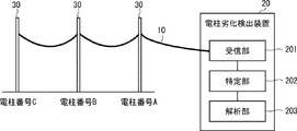
- FIG. 1 a configuration example of the utility pole deterioration detection system according to the first embodiment will be described with reference to FIG.
- three utility poles 30 are shown for the sake of simplification of the description, but the number of utility poles 30 may be two or more. Further, it is assumed that the utility pole numbers of the three utility poles 30 shown in FIG. 1 are A, B, and C, respectively.
- the utility pole deterioration detection system includes a sensing optical fiber 10 and a utility pole deterioration detection device 20. Further, the utility pole deterioration detection device 20 includes a receiving unit 201, a specific unit 202, and an analysis unit 203.
- the sensing optical fiber 10 is laid on a plurality of utility poles 30 (three utility poles 30 in FIG. 1).
- the sensing optical fiber 10 may be laid on the utility pole 30 in the form of a cable formed by covering one or more sensing optical fibers 10. Further, the sensing optical fiber 10 may be an existing communication optical fiber or a newly installed optical fiber.
- the receiving unit 201 incidents pulsed light on the sensing optical fiber 10 and transmits the reflected light or scattered light generated by the pulsed light being transmitted through the sensing optical fiber 10 via the sensing optical fiber 10. , Received as return light (optical signal).
- the utility pole 30 is vibrating not a little due to the influence of natural vibration of the ground, automobiles running in the vicinity, wind, and the like.
- the vibration of the utility pole 30 is transmitted to the sensing optical fiber 10, and the characteristics (for example, wavelength) of the return light transmitted through the sensing optical fiber 10 are changed. Therefore, the sensing optical fiber 10 can detect vibration information indicating vibration generated on the utility pole 30. Further, since the characteristics of the return light transmitted through the sensing optical fiber 10 change according to the vibration information of the utility pole 30 detected by the sensing optical fiber 10, the vibration of the utility pole 30 detected by the sensing optical fiber 10 Contains information.
- the vibration information of the utility pole 30 is a pattern that dynamically fluctuates, and shows a unique vibration pattern in which the strength of vibration, the vibration position, the transition of fluctuation of the frequency, and the like are different. Therefore, the specifying unit 202 can specify the natural frequency of the utility pole 30 by analyzing the dynamic change of the vibration pattern of the utility pole 30 indicated by the vibration information.
- the specific unit 202 holds in advance a corresponding table in which the utility pole number of the utility pole 30 and the position information (position information indicating the distance from the utility pole deterioration detection device 20) are associated with each of the plurality of utility poles 30. ..
- FIG. 2 shows an example of the contents of the corresponding table.
- the specific unit 202 is based on, for example, the time difference between the reception unit 201 transmitting the pulsed light to the sensing optical fiber 10 and the reception of the return light, the intensity of the return light received by the reception unit 201, and the like. It is possible to specify at which position (distance from the utility pole deterioration detection device 20) the return light is generated on the sensing optical fiber 10.
- the identification unit 202 collates the position on the sensing optical fiber 10 in which the return light is generated with the corresponding table shown in FIG. 2, and determines which electric pole 30 the return light is generated in. It is possible to identify.
- the identification unit 202 identifies the return light generated by each of the plurality of utility poles 30 from the return light received by the reception unit 201, and based on the vibration information included in the specified return light, the plurality of utility poles.
- Each of the 30 natural frequencies is specified.
- the analysis unit 203 can analyze the deterioration state of at least one utility pole 30 among the plurality of utility poles 30 based on the natural frequencies of the plurality of utility poles 30.
- the analysis unit 203 may analyze the deterioration state of at least one utility pole 30 among the plurality of utility poles 30 based on the distribution information showing the distribution of the natural frequencies of the plurality of utility poles 30. For example, the analysis unit 203 can analyze that if there is a utility pole 30 whose natural frequency is lower than that of the other utility pole 30, the utility pole 30 is deteriorated.
- each of the plurality of utility poles 30 has unique characteristics (for example, the type of the installation road surface on which the utility pole 30 is installed, the material, density, thickness, length, and overburden depth of the utility pole 30, and the utility pole 30. It has the type, thickness, and number of supporting wires). Therefore, it is considered that the natural frequency of the utility pole 30 also differs depending on the characteristics of the utility pole 30.
- the analysis unit 203 clusters the plurality of utility poles 30 into clusters based on the characteristics of the plurality of utility poles 30, and based on the distribution information of the natural frequencies of one or more utility poles 30 belonging to the same cluster.
- the deterioration state of at least one utility pole 30 belonging to the cluster may be analyzed.
- the deterioration state of the utility pole 30 belonging to the cluster can be analyzed based on the distribution of the natural frequency of the utility pole 30 after eliminating the influence of the characteristics of the utility pole 30, so that the analysis accuracy of the deterioration state of the utility pole 30 is improved. Can be planned.
- each feature of the utility pole 30 includes a feature having a high contribution rate to the natural frequency and a feature having a low contribution rate. Therefore, by performing clustering so that the utility poles 30 having similar characteristics having a high contribution rate to the natural frequency belong to the same cluster, it is possible to further improve the analysis accuracy of the deterioration state of the utility pole 30. it is conceivable that.
- the analysis unit 203 identifies a feature having a high contribution rate to the natural frequency from each feature of the utility pole 30, and clusters a plurality of utility poles 30 into a cluster based on the specified feature of each of the plurality of utility poles 30. You may. As a result, the accuracy of analysis of the deteriorated state of the utility pole 30 can be further improved.
- a method of identifying a feature having a high contribution rate to the natural frequency from each feature of the utility pole 30, for example a multiple regression analysis is performed to calculate the contribution rate of each feature of the utility pole 30 to the natural frequency. Methods and the like can be considered, but the method is not limited to this.
- the analysis unit 203 may hold soundness information indicating the soundness of each of the plurality of utility poles 30. Then, the analysis unit 203 may analyze the deterioration state of at least one utility pole 30 belonging to the cluster based on the distribution information of the natural frequencies of each of the sound one or more utility poles 30 belonging to the same cluster. .. More specifically, the analysis unit 203 bases on the distribution information of the natural frequencies of one or more healthy electric columns 30 belonging to the same cluster, and the standard natural vibration of the healthy electric columns 30 belonging to the cluster.
- the standard natural frequency which is a number, is calculated, and the deterioration state of the electric column 30 to be analyzed is analyzed based on the standard natural frequency of the cluster and the natural frequency of the electric column 30 to be analyzed belonging to the cluster. Is also good. As a result, the accuracy of analysis of the deteriorated state of the utility pole 30 can be further improved.
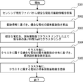
- the receiving unit 201 receives the return light including the vibration information detected by the sensing optical fiber 10 from the sensing optical fiber 10 (step S101).
- the specifying unit 202 specifies the natural frequencies of the plurality of utility poles 30 based on the vibration information included in the return light received by the receiving unit 201 (step S102).
- the analysis unit 203 analyzes the deterioration state of at least one utility pole 30 among the plurality of utility poles 30 based on the natural frequencies of the plurality of utility poles 30 specified by the specific unit 202 (step S103).
- the receiving unit 201 receives the vibration information detected by the sensing optical fiber 10, and the specific unit 202 is unique to each of the plurality of utility poles 30 based on the vibration information.
- the frequency is specified, and the analysis unit 203 analyzes the deterioration state of at least one utility pole 30 among the plurality of utility poles 30 based on the natural frequencies of the plurality of utility poles 30. Therefore, the deteriorated state of the utility pole 30 can be detected with high accuracy.
- the deterioration state of a plurality of utility poles 30 can be analyzed simultaneously and remotely by using the sensing optical fiber 10, it becomes easy to grasp the deterioration state of the utility pole 30. At the same time, the cost for grasping the deteriorated state of the utility pole 30 can be reduced.
- an existing communication optical fiber can be used as the sensing optical fiber 10.
- an existing optical fiber for communication may be used, and as in Patent Document 1, the optical fiber may be laid linearly or spirally in the vertical direction of the utility pole. Unlike Patent Document 2, it is not necessary to lay a core wire for detecting nesting. Therefore, since a dedicated structure for detecting the deterioration state of the utility pole 30 is not required, the utility pole deterioration detection system can be constructed at low cost.
- the optical fiber sensing technology using the sensing optical fiber 10 as a sensor is used. Therefore, advantages such as being unaffected by electromagnetic noise, eliminating the need for power supply to the sensor, being excellent in environmental resistance, and facilitating maintenance can be obtained.
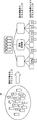
- the utility pole deterioration detection system according to the second embodiment is a more specific version of the utility pole deterioration detection system according to the first embodiment described above. Specifically, the utility pole deterioration detection system according to the second embodiment replaces the utility pole deterioration detection device 20 of the first embodiment described above with the utility pole deterioration detection device 20A, and has an external system configuration. , The same as the above-described first embodiment.
- the utility pole deterioration detection device 20A includes a receiving unit 211, a collecting unit 212, a natural frequency calculation unit 213, a contribution rate analysis unit 214, and a utility pole DB (Database) 215. It includes a clustering unit 216, a standard natural frequency calculation unit 217, a standard natural frequency DB 218, and a deterioration degree calculation unit 219.
- the receiving unit 211 corresponds to the receiving unit 201 of FIG.
- the combination of the collecting unit 212 and the natural frequency calculation unit 213 corresponds to the specific unit 202 of FIG.
- the combination of the contribution rate analysis unit 214, the utility pole DB 215, the clustering unit 216, the standard natural frequency calculation unit 217, the standard natural frequency DB 218, and the deterioration degree calculation unit 219 corresponds to the analysis unit 203 of FIG.
- the receiving unit 211 incidents pulsed light on the sensing optical fiber 10 and transmits the reflected light or scattered light generated by the pulsed light being transmitted through the sensing optical fiber 10 via the sensing optical fiber 10. , Received as return light.
- the return light received by the receiving unit 211 includes the return light generated in each of the plurality of utility poles 30.
- each return light includes vibration information indicating vibration generated in the corresponding utility pole 30.
- the utility pole DB 215 has, for each of the plurality of utility poles 30 on which the sensing optical fiber 10 is laid, the utility pole number of the utility pole 30, the soundness information indicating the soundness of the utility pole 30, and the position information of the utility pole 30 (the utility pole deterioration detection device). Position information indicating the distance from 20A) and the characteristics of the utility pole 30 (for example, the type of the installation road surface on which the utility pole 30 is installed, the material, density, thickness, length, and overburden depth of the utility pole 30). , The type, thickness, number, etc. of the electric wires supported by the utility pole 30) are registered in this database.
- FIG. 5 shows an example of the contents of the utility pole DB 215.
- the collecting unit 212 collects vibration information included in the return light received by the receiving unit 211.
- the collection unit 212 returns, for example, based on the time difference between the reception unit 211 transmitting the pulsed light to the sensing optical fiber 10 and the reception of the return light, the intensity of the return light received by the reception unit 211, and the like. It is possible to specify at which position (distance from the utility pole deterioration detection device 20A) the light is generated on the sensing optical fiber 10. Further, in the utility pole DB 215, as described above, the utility pole number and the position information of the utility pole 30 are registered for each of the plurality of utility poles 30.
- the collecting unit 212 can identify which utility pole 30 the return light is generated by by collating the position on the sensing optical fiber 10 where the return light is generated with the utility pole DB 215. Is. Therefore, the collecting unit 212 can collect the vibration information of the specific utility pole 30.
- the collecting unit 212 is not limited to using the utility pole DB 215.
- the collecting unit 212 holds a corresponding table as shown in FIG. 2 according to the first embodiment described above, and uses the corresponding table to specify which utility pole 30 the return light is generated from. You may.
- the natural frequency calculation unit 213 calculates the natural frequency of the utility pole 30 based on the vibration information of the utility pole 30 collected by the collection unit 212.
- the vibration information of the utility pole 30 collected by the collecting unit 212 is a vibration pattern peculiar to the utility pole 30, and shows a dynamically fluctuating vibration pattern. Therefore, the natural frequency calculation unit 213 can calculate the natural frequency of the utility pole 30 by analyzing the dynamic change of the vibration pattern of the utility pole 30.
- the contribution rate analysis unit 214 calculates a feature Top K having a high contribution rate to the natural frequency from each feature of the utility pole 30 registered in the utility pole DB 215, and holds the calculated feature Top K.
- Feature Top K may include only one feature or may include a plurality of features.
- a method of calculating the feature Top K in the contribution rate analysis unit 214 for example, a method of performing multiple regression analysis to calculate the contribution rate of each feature of the utility pole 30 to the natural frequency can be considered.
- the calculation method of the feature Top K is not limited to this.
- the clustering unit 216 clusters one or more sound utility poles 30 out of a plurality of utility poles 30 on which the sensing optical fiber 10 is laid into a cluster.
- the concept of this clustering operation is shown in FIG.
- the clustering unit 216 first clusters one or more healthy utility poles 30 into a cluster based on the natural frequency calculated by the natural frequency calculation unit 213, and further clusters the contribution rate analysis. Clustering is performed in a cluster based on the feature Top K calculated by the unit 214.
- the standard natural frequency calculation unit 217 statistically divides each cluster clustered by the clustering unit 216 into the cluster based on the distribution information of the natural frequencies of one or more sound poles 30 belonging to the cluster.
- the standard natural frequency which is the standard natural frequency of the sound electric column 30 to which the electric column 30 belongs, is calculated.
- the standard natural frequency of a cluster in the standard natural frequency calculation unit 217 for example, the average value, the median value, and the mode of the natural frequencies of one or more sound electric columns 30 belonging to the cluster are used.
- a method of calculating the value or the like as the standard natural frequency can be considered.
- the calculation method of the standard natural frequency is not limited to this.
- the standard natural frequency DB 218 is a database in which the utility pole number of the utility pole 30 belonging to the cluster, the standard natural frequency of the cluster, etc. are registered for each cluster clustered by the clustering unit 216.
- FIG. 7 shows an example of the contents of the standard natural frequency DB 218.
- the clustering unit 216 determines the cluster to which the utility pole 30 to be analyzed belongs based on the feature Top K of the utility pole 30 to be analyzed registered in the utility pole DB 215.
- the deterioration degree calculation unit 219 analyzes based on the standard natural frequency of the cluster to which the utility pole 30 to be analyzed belongs and the natural frequency of the utility pole 30 to be analyzed. The degree of deterioration of the target utility pole 30 is calculated. For example, the deterioration degree calculation unit 219 calculates the deterioration degree of the utility pole 30 to be analyzed by using the following mathematical formula 1.
- the deterioration degree calculation unit 219 holds in advance a threshold value used for analyzing the deterioration state of the utility pole 30 belonging to the cluster for each cluster clustered by the clustering unit 216. Then, the deterioration degree calculation unit 219 compares the deterioration degree of the utility pole 30 to be analyzed with the threshold value of the cluster to which the utility pole 30 to be analyzed belongs by using the following mathematical formula 2. When the degree of deterioration exceeds the threshold value, the degree of deterioration calculation unit 219 analyzes that the utility pole 30 to be analyzed is deteriorated.
- the threshold value for each cluster may be set statistically based on the distribution information of the natural frequency of the utility pole 30 belonging to the cluster. Further, the analyst may analyze the actual utility pole 30 analyzed by the deterioration degree calculation unit 219 to measure the actual deterioration degree, and reflect the actual measurement result in the threshold setting. ..
- the deterioration degree calculation unit 219 may notify an alert.
- the alert notification destination may be, for example, a terminal possessed by an observer who monitors the utility pole 30 to be analyzed, a terminal installed in the monitoring center, or the like.
- the alert notification method may be, for example, a method of displaying a GUI (Graphical User Interface) screen on the display or monitor of the notification destination terminal, or a method of outputting a message by voice from the speaker of the notification destination terminal. ..
- GUI Graphic User Interface
- the collecting unit 212 selects a sound utility pole 30 from a plurality of utility poles 30 on which the sensing optical fiber 10 is laid, based on the soundness information registered in the utility pole DB 215. Identify. Here, it is assumed that one or more sound utility poles 30 have been identified. Then, the collecting unit 212 collects the vibration information included in the return light generated by each of one or more sound utility poles 30 among the return lights received by the receiving unit 211 (step S201).
- the natural frequency calculation unit 213 calculates the natural frequency of each of the sound one or more utility poles 30 based on the vibration information of each of the sound one or more utility poles 30 collected by the collection unit 212. (Step S202).
- the contribution rate analysis unit 214 includes the natural frequencies of each of the sound one or more utility poles 30 calculated by the natural frequency calculation unit 213, and the sound one or more utility poles 30 registered in the utility pole DB 215. Based on each of the features of the above, the contribution ratio of each feature of the utility pole 30 registered in the utility pole DB 215 to the natural frequency is analyzed (step S203).
- the contribution rate analysis unit 214 determines the contribution rate to the natural frequency from each feature of the utility pole 30 based on the analysis result of the contribution rate of each feature of the utility pole 30 registered in the utility pole DB 215 to the natural frequency.
- the characteristic Top K having a high value is calculated, and the calculated characteristic Top K is retained (step S204).
- Feature Top K may include only one feature or may include a plurality of features.
- steps S301 and S302 similar to steps S201 and S202 of FIG. 8 are performed.
- the clustering unit 216 clusters one or more sound utility poles 30 into a cluster based on the natural frequency calculated by the natural frequency calculation unit 213, and further, the contribution rate analysis unit 214 calculates it. Clustering into clusters based on feature Top K (step S303). At this time, the clustering unit 216 does not need to target all of the sound utility poles 30 specified by the collecting unit 212 as clustering targets, and may target only a part of them.
- the standard natural frequency calculation unit 217 belongs to each cluster clustered by the clustering unit 216, based on the distribution information of the natural frequencies of one or more sound utility poles 30 belonging to the cluster.
- the standard natural frequency of a sound utility pole 30 is calculated (step S304).
- the clustering unit 216 registers each utility pole number of one or more sound utility poles 30 belonging to the cluster in the standard natural frequency DB 218 for each cluster clustered by the clustering unit 216. Further, the standard natural frequency calculation unit 217 registers the standard natural frequency of the cluster in the standard natural frequency DB 218 for each cluster clustered by the clustering unit 216 (step S305).
- FIG. 10 an example of an operation flow for analyzing the deterioration state of the utility pole 30 to be analyzed will be described.
- an arbitrary number (or all of them) of utility poles 30 among a plurality of utility poles 30 on which the sensing optical fiber 10 is laid are sequentially analyzed one by one, and one utility pole 30 is analyzed. Will be described in order, assuming that the processing of FIG. 10 is performed.
- the collecting unit 212 collects vibration information included in the return light generated in the utility pole 30 to be analyzed among the return light received by the receiving unit 211 (step S401).
- the natural frequency calculation unit 213 calculates the natural frequency of the utility pole 30 to be analyzed based on the vibration information of the utility pole 30 to be analyzed collected by the collection unit 212 (step S402).
- the clustering unit 216 determines the cluster to which the utility pole 30 to be analyzed belongs based on the feature Top K of the utility pole 30 to be analyzed registered in the utility pole DB 215 (step S403).
- the process of step S403 can be omitted.
- the deterioration degree calculation unit 219 includes the standard natural frequency of the cluster to which the utility pole 30 to be analyzed belongs, which is registered in the standard natural frequency DB 218, and the utility pole 30 to be analyzed calculated by the natural frequency calculation unit 213.
- the degree of deterioration of the utility pole 30 to be analyzed is calculated based on the natural frequency of (step S404).
- the deterioration degree calculation unit 219 determines whether or not the deterioration degree of the utility pole 30 to be analyzed exceeds the threshold value of the cluster to which the utility pole 30 to be analyzed belongs (step S405).
- step S405 when the degree of deterioration of the utility pole 30 to be analyzed exceeds the threshold value (Yes in step S405), the deterioration degree calculation unit 219 analyzes that the utility pole 30 to be analyzed is deteriorated and notifies an alert. (Step S406).
- the deterioration state of any number of utility poles 30 may be analyzed at regular intervals, or when requested by an observer or a monitoring center. Further, an arbitrary number of utility poles 30 to be analyzed may be set in advance, or may be designated by an observer or a monitoring center.
- the utility pole 30 to be analyzed preferably belongs to one cluster, but may belong to a plurality of clusters.
- the cluster to which the utility pole 30 to be analyzed belongs is determined to be a plurality of clusters.
- the processes of steps S404 to S406 may be performed for each of the plurality of clusters thereafter.
- the natural frequency calculation unit 213 calculates the natural frequency of the sound electric column 30 based on the vibration information of the sound electric column 30, and the clustering unit 216 calculates the natural frequency of the sound electric column 30.
- the electric poles 30 are clustered in a cluster, and the standard natural frequency calculation unit 217 standardizes the sound electric poles 30 belonging to the cluster based on the distribution information of the natural frequencies of the sound electric poles 30 belonging to the cluster for each cluster. Calculate the natural frequency. Therefore, the standard natural frequency can be calculated from the vibration information of the utility pole 30.
- the natural frequency calculation unit 213 calculates the natural frequency of the utility pole 30 to be analyzed based on the vibration information of the utility pole 30 to be analyzed, and the clustering unit 216 is the analysis target.
- the deterioration degree calculation unit 219 determines the cluster to which the utility pole 30 belongs, and the deterioration degree calculation unit 219 determines the utility pole to be analyzed based on the standard natural frequency of the cluster to which the utility pole 30 to be analyzed belongs and the natural frequency of the utility pole 30 to be analyzed.
- the degree of deterioration of 30 is calculated. Therefore, the deteriorated state of the utility pole 30 can be detected with high accuracy.
- Other effects are the same as those in the first embodiment described above.
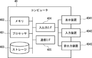
- the computer 40 includes a processor 401, a memory 402, a storage 403, an input / output interface (input / output I / F) 404, a communication interface (communication I / F) 405, and the like.
- the processor 401, the memory 402, the storage 403, the input / output interface 404, and the communication interface 405 are connected by a data transmission line for transmitting and receiving data to and from each other.
- the processor 401 is, for example, an arithmetic processing unit such as a CPU (Central Processing Unit) or a GPU (Graphics Processing Unit).
- the memory 402 is, for example, a memory such as a RAM (Random Access Memory) or a ROM (Read Only Memory).
- the storage 403 is, for example, a storage device such as an HDD (Hard Disk Drive), an SSD (Solid State Drive), or a memory card. Further, the storage 403 may be a memory such as a RAM or a ROM.
- the storage 403 stores a program that realizes the functions of the components included in the utility pole deterioration detection devices 20 and 20A. By executing each of these programs, the processor 401 realizes the functions of the components included in the utility pole deterioration detection devices 20 and 20A, respectively. Here, when executing each of the above programs, the processor 401 may read these programs onto the memory 402 and then execute the programs, or may execute the programs without reading them onto the memory 402. The memory 402 and the storage 403 also play a role of storing information and data held by the components included in the utility pole deterioration detection devices 20 and 20A.
- Non-temporary computer-readable media include various types of tangible storage media.
- Examples of non-temporary computer-readable media include magnetic recording media (eg, flexible disks, magnetic tapes, hard disk drives), photomagnetic recording media (eg, photomagnetic discs), CD-ROMs (Compact Disc-ROMs), CDs. -R (CD-Recordable), CD-R / W (CD-ReWritable), semiconductor memory (for example, mask ROM, PROM (Programmable ROM), EPROM (Erasable PROM), flash ROM, RAM.
- the program also includes.
- the computer-readable medium can supply the program to the computer via a wired communication path such as an electric wire and an optical fiber, or a wireless communication path.
- the input / output interface 404 is connected to a display device 4041, an input device 4042, a sound output device 4043, and the like.
- the display device 4041 is a device that displays a screen corresponding to drawing data processed by the processor 401, such as an LCD (Liquid Crystal Display), a CRT (Cathode Ray Tube) display, and a monitor.
- the input device 4042 is a device that receives an operator's operation input, and is, for example, a keyboard, a mouse, a touch sensor, and the like.
- the display device 4041 and the input device 4042 may be integrated and realized as a touch panel.
- the sound output device 4043 is a device such as a speaker that acoustically outputs sound corresponding to acoustic data processed by the processor 401.
- the communication interface 405 sends and receives data to and from an external device.
- the communication interface 405 communicates with an external device via a wired communication path or a wireless communication path.
- the utility pole deterioration detection devices 20 and 20A are provided with a plurality of components, but the present invention is not limited to this.
- the components provided in the utility pole deterioration detection devices 20 and 20A are not limited to being provided in one device, and may be distributed in a plurality of devices.
- the analysis target may be a structure such as a bridge, a tunnel, a pipe, or a dam.
- these structures are targeted for analysis, by laying the sensing optical fibers 10 at a plurality of locations of these structures, it is possible to analyze the deterioration state of each of the plurality of locations.
- Appendix 1 Optical fibers for sensing laid on multiple utility poles, A receiving unit that receives vibration information detected by the sensing optical fiber, and Based on the vibration information, a specific unit that specifies the natural frequency of each of the plurality of utility poles, and An analysis unit that analyzes the deterioration state of at least one of the plurality of utility poles based on the natural frequency of each of the plurality of utility poles.
- a utility pole deterioration detection system Optical fibers for sensing laid on multiple utility poles.
- the analysis unit Holds soundness information indicating the soundness of each of the plurality of utility poles, Based on the soundness information, a sound utility pole is identified from the plurality of utility poles, and the utility pole is identified. Based on the distribution information of the natural frequencies of each of one or more healthy utility poles belonging to the same cluster, the deterioration state of at least one utility pole belonging to the cluster is analyzed.
- the utility pole deterioration detection system according to Appendix 3. (Appendix 5)
- the analysis unit Based on the distribution information of the natural frequencies of each of one or more healthy utility poles belonging to the same cluster, the standard natural frequency, which is the standard natural frequency of the healthy utility poles belonging to the cluster, is calculated.
- the utility pole deterioration detection system according to Appendix 4.
- the analysis unit Among the characteristics of the utility pole, the feature having a high contribution rate to the natural frequency of the utility pole was identified.
- the utility pole deterioration detection system according to any one of Appendix 3 to 5.
- Appendix 7) It is a utility pole deterioration detection method using a utility pole deterioration detection system.
- a reception step that receives vibration information detected by sensing optical fibers laid on multiple utility poles, Based on the vibration information, a specific step of specifying the natural frequency of each of the plurality of utility poles, and An analysis step for analyzing the deterioration state of at least one utility pole among the plurality of utility poles based on the natural frequency of each of the plurality of utility poles.
- Utility pole deterioration detection method including. (Appendix 8) In the analysis step, Based on the distribution information showing the distribution of the natural frequencies of each of the plurality of utility poles, the deterioration state of at least one of the plurality of utility poles is analyzed.
- the utility pole deterioration detection method according to Appendix 7.
- the deterioration state of at least one utility pole belonging to the cluster is analyzed.
- the utility pole deterioration detection method according to Appendix 9. (Appendix 11)
- the standard natural frequency which is the standard natural frequency of the healthy utility poles belonging to the cluster, is calculated.
- the deterioration state of the utility pole to be analyzed is analyzed.
Landscapes
- Physics & Mathematics (AREA)
- General Physics & Mathematics (AREA)
- Optics & Photonics (AREA)
- Measurement Of Mechanical Vibrations Or Ultrasonic Waves (AREA)
- Optical Transform (AREA)
- Light Guides In General And Applications Therefor (AREA)
- Electric Cable Installation (AREA)
- Suspension Of Electric Lines Or Cables (AREA)
Priority Applications (3)
| Application Number | Priority Date | Filing Date | Title |
|---|---|---|---|
| PCT/JP2020/002132 WO2021149192A1 (ja) | 2020-01-22 | 2020-01-22 | 電柱劣化検出システム、電柱劣化検出方法、及び電柱劣化検出装置 |
| JP2021572193A JP7327522B2 (ja) | 2020-01-22 | 2020-01-22 | 電柱劣化検出システム、電柱劣化検出方法、及び電柱劣化検出装置 |
| US17/790,904 US20230024381A1 (en) | 2020-01-22 | 2020-01-22 | Utility pole degradation detection system, utility pole degradation detection method, and utility pole degradation detection device |
Applications Claiming Priority (1)
| Application Number | Priority Date | Filing Date | Title |
|---|---|---|---|
| PCT/JP2020/002132 WO2021149192A1 (ja) | 2020-01-22 | 2020-01-22 | 電柱劣化検出システム、電柱劣化検出方法、及び電柱劣化検出装置 |
Publications (1)
| Publication Number | Publication Date |
|---|---|
| WO2021149192A1 true WO2021149192A1 (ja) | 2021-07-29 |
Family
ID=76991825
Family Applications (1)
| Application Number | Title | Priority Date | Filing Date |
|---|---|---|---|
| PCT/JP2020/002132 Ceased WO2021149192A1 (ja) | 2020-01-22 | 2020-01-22 | 電柱劣化検出システム、電柱劣化検出方法、及び電柱劣化検出装置 |
Country Status (3)
| Country | Link |
|---|---|
| US (1) | US20230024381A1 (https=) |
| JP (1) | JP7327522B2 (https=) |
| WO (1) | WO2021149192A1 (https=) |
Cited By (1)
| Publication number | Priority date | Publication date | Assignee | Title |
|---|---|---|---|---|
| JPWO2023021598A1 (https=) * | 2021-08-18 | 2023-02-23 |
Families Citing this family (1)
| Publication number | Priority date | Publication date | Assignee | Title |
|---|---|---|---|---|
| CN116917703A (zh) * | 2021-02-17 | 2023-10-20 | 日本电信电话株式会社 | 电线杆位置确定方法和架空光缆的状态推定方法 |
Citations (7)
| Publication number | Priority date | Publication date | Assignee | Title |
|---|---|---|---|---|
| JP2007183166A (ja) * | 2006-01-06 | 2007-07-19 | Chugoku Electric Power Co Inc:The | 電柱応力評価装置、電柱応力評価システム、電柱応力評価方法及び電柱 |
| JP2008067467A (ja) * | 2006-09-06 | 2008-03-21 | Chugoku Electric Power Co Inc:The | 電柱折損状況監視システム及び該電柱折損状況監視システムで使用される電柱 |
| JP2008107309A (ja) * | 2006-09-29 | 2008-05-08 | Furukawa Electric Co Ltd:The | 衝撃振動検知装置 |
| JP2015053832A (ja) * | 2013-09-09 | 2015-03-19 | 中国電力株式会社 | 営巣検出システム及び営巣検出方法 |
| JP2018096866A (ja) * | 2016-12-14 | 2018-06-21 | 日本電信電話株式会社 | 構造物劣化判定装置とその方法 |
| JP2018124205A (ja) * | 2017-02-02 | 2018-08-09 | 株式会社東芝 | 劣化診断方法、劣化診断システム及びセンサ |
| JP2020010419A (ja) * | 2018-07-03 | 2020-01-16 | 東北電力株式会社 | 電柱劣化度推定方法、電柱劣化度推定装置、電柱、電柱荷重推定方法、及び、電柱荷重推定装置 |
Family Cites Families (2)
| Publication number | Priority date | Publication date | Assignee | Title |
|---|---|---|---|---|
| US9267925B2 (en) * | 2012-09-07 | 2016-02-23 | Polexpert, Llc | Pole integrity meter and method of determining pole integrity |
| EP3845944A4 (en) * | 2018-08-30 | 2021-10-06 | NEC Corporation | SYSTEM FOR DETECTING THE DEGRADATION OF A POWER POST, DEVICE FOR DETECTING THE DEGRADATION OF A POWER POST, METHOD FOR DETECTING THE DEGRADATION OF A POWER POST AND NON-TRANSFERABLE COMPUTER-READABLE MEDIUM |
-
2020
- 2020-01-22 WO PCT/JP2020/002132 patent/WO2021149192A1/ja not_active Ceased
- 2020-01-22 JP JP2021572193A patent/JP7327522B2/ja active Active
- 2020-01-22 US US17/790,904 patent/US20230024381A1/en not_active Abandoned
Patent Citations (7)
| Publication number | Priority date | Publication date | Assignee | Title |
|---|---|---|---|---|
| JP2007183166A (ja) * | 2006-01-06 | 2007-07-19 | Chugoku Electric Power Co Inc:The | 電柱応力評価装置、電柱応力評価システム、電柱応力評価方法及び電柱 |
| JP2008067467A (ja) * | 2006-09-06 | 2008-03-21 | Chugoku Electric Power Co Inc:The | 電柱折損状況監視システム及び該電柱折損状況監視システムで使用される電柱 |
| JP2008107309A (ja) * | 2006-09-29 | 2008-05-08 | Furukawa Electric Co Ltd:The | 衝撃振動検知装置 |
| JP2015053832A (ja) * | 2013-09-09 | 2015-03-19 | 中国電力株式会社 | 営巣検出システム及び営巣検出方法 |
| JP2018096866A (ja) * | 2016-12-14 | 2018-06-21 | 日本電信電話株式会社 | 構造物劣化判定装置とその方法 |
| JP2018124205A (ja) * | 2017-02-02 | 2018-08-09 | 株式会社東芝 | 劣化診断方法、劣化診断システム及びセンサ |
| JP2020010419A (ja) * | 2018-07-03 | 2020-01-16 | 東北電力株式会社 | 電柱劣化度推定方法、電柱劣化度推定装置、電柱、電柱荷重推定方法、及び、電柱荷重推定装置 |
Cited By (3)
| Publication number | Priority date | Publication date | Assignee | Title |
|---|---|---|---|---|
| JPWO2023021598A1 (https=) * | 2021-08-18 | 2023-02-23 | ||
| WO2023021598A1 (ja) * | 2021-08-18 | 2023-02-23 | 日本電気株式会社 | 情報処理装置、情報処理方法、コンピュータ可読媒体、及び点検システム |
| JP7643556B2 (ja) | 2021-08-18 | 2025-03-11 | 日本電気株式会社 | 情報処理装置、情報処理方法、プログラム、及び点検システム |
Also Published As
| Publication number | Publication date |
|---|---|
| US20230024381A1 (en) | 2023-01-26 |
| JPWO2021149192A1 (https=) | 2021-07-29 |
| JP7327522B2 (ja) | 2023-08-16 |
Similar Documents
| Publication | Publication Date | Title |
|---|---|---|
| JP7124875B2 (ja) | 電柱位置特定システム、電柱位置特定装置、電柱位置特定方法、及びプログラム | |
| US20240271969A1 (en) | Utility pole deterioration detection system, utility pole deterioration detection apparatus, utility pole deterioration detection method, and non-transitory computer readable medium | |
| US12092514B2 (en) | Optical fiber sensing system, optical fiber sensing device, and method for detecting pipe deterioration | |
| JP7124876B2 (ja) | 状態特定システム、状態特定装置、状態特定方法、及びプログラム | |
| US20220044552A1 (en) | Road monitoring system, road monitoring device, road monitoring method, and non-transitory computer-readable medium | |
| CN109547910B (zh) | 电子设备声学组件性能测试方法、装置、设备及存储介质 | |
| JPWO2017064855A1 (ja) | 構造物異常検知システム、構造物異常検知方法及び記録した記録媒体 | |
| JP7327522B2 (ja) | 電柱劣化検出システム、電柱劣化検出方法、及び電柱劣化検出装置 | |
| CN119573860A (zh) | 一种电缆振动状态监测方法、装置、电子设备及存储介质 | |
| CN117686021B (zh) | 一种基于数据分析的智能化管道线缆管控系统 | |
| WO2024004119A1 (ja) | センシングシステム、センシング機器、及びセンシング方法 | |
| CN119727896B (zh) | 基于多频率探测脉冲的远距离光缆路由采集方法及系统 | |
| JP7405161B2 (ja) | 構造物劣化検出システム、構造物劣化検出方法、及び構造物劣化検出装置 | |
| US20210372828A1 (en) | Civil engineering structure monitoring system, civil engineering structure monitoring apparatus, civil engineering structure monitoring method, and non-transitory computer-readable medium | |
| JP2024059436A (ja) | 評価装置、評価方法、及びプログラム | |
| WO2026033600A1 (ja) | 光ファイバケーブル点検箇所特定方法 | |
| WO2025062511A1 (ja) | 振動解析装置 | |
| CN116964424A (zh) | 线缆试验系统、分析装置、线缆试验方法以及程序 |
Legal Events
| Date | Code | Title | Description |
|---|---|---|---|
| 121 | Ep: the epo has been informed by wipo that ep was designated in this application |
Ref document number: 20915965 Country of ref document: EP Kind code of ref document: A1 |
|
| ENP | Entry into the national phase |
Ref document number: 2021572193 Country of ref document: JP Kind code of ref document: A |
|
| NENP | Non-entry into the national phase |
Ref country code: DE |
|
| 122 | Ep: pct application non-entry in european phase |
Ref document number: 20915965 Country of ref document: EP Kind code of ref document: A1 |