WO2021145266A1 - 画像処理装置及び方法 - Google Patents
画像処理装置及び方法 Download PDFInfo
- Publication number
- WO2021145266A1 WO2021145266A1 PCT/JP2021/000328 JP2021000328W WO2021145266A1 WO 2021145266 A1 WO2021145266 A1 WO 2021145266A1 JP 2021000328 W JP2021000328 W JP 2021000328W WO 2021145266 A1 WO2021145266 A1 WO 2021145266A1
- Authority
- WO
- WIPO (PCT)
- Prior art keywords
- image
- drug
- visibility
- individual
- image processing
- Prior art date
- Legal status (The legal status is an assumption and is not a legal conclusion. Google has not performed a legal analysis and makes no representation as to the accuracy of the status listed.)
- Ceased
Links
Images


Classifications
-
- G—PHYSICS
- G06—COMPUTING OR CALCULATING; COUNTING
- G06V—IMAGE OR VIDEO RECOGNITION OR UNDERSTANDING
- G06V10/00—Arrangements for image or video recognition or understanding
- G06V10/20—Image preprocessing
- G06V10/25—Determination of region of interest [ROI] or a volume of interest [VOI]
-
- G—PHYSICS
- G06—COMPUTING OR CALCULATING; COUNTING
- G06V—IMAGE OR VIDEO RECOGNITION OR UNDERSTANDING
- G06V10/00—Arrangements for image or video recognition or understanding
- G06V10/98—Detection or correction of errors, e.g. by rescanning the pattern or by human intervention; Evaluation of the quality of the acquired patterns
-
- G—PHYSICS
- G06—COMPUTING OR CALCULATING; COUNTING
- G06T—IMAGE DATA PROCESSING OR GENERATION, IN GENERAL
- G06T5/00—Image enhancement or restoration
- G06T5/70—Denoising; Smoothing
-
- G—PHYSICS
- G06—COMPUTING OR CALCULATING; COUNTING
- G06T—IMAGE DATA PROCESSING OR GENERATION, IN GENERAL
- G06T5/00—Image enhancement or restoration
- G06T5/90—Dynamic range modification of images or parts thereof
- G06T5/94—Dynamic range modification of images or parts thereof based on local image properties, e.g. for local contrast enhancement
-
- G—PHYSICS
- G06—COMPUTING OR CALCULATING; COUNTING
- G06V—IMAGE OR VIDEO RECOGNITION OR UNDERSTANDING
- G06V10/00—Arrangements for image or video recognition or understanding
- G06V10/10—Image acquisition
- G06V10/12—Details of acquisition arrangements; Constructional details thereof
- G06V10/14—Optical characteristics of the device performing the acquisition or on the illumination arrangements
- G06V10/141—Control of illumination
-
- G—PHYSICS
- G06—COMPUTING OR CALCULATING; COUNTING
- G06V—IMAGE OR VIDEO RECOGNITION OR UNDERSTANDING
- G06V10/00—Arrangements for image or video recognition or understanding
- G06V10/20—Image preprocessing
- G06V10/255—Detecting or recognising potential candidate objects based on visual cues, e.g. shapes
-
- G—PHYSICS
- G06—COMPUTING OR CALCULATING; COUNTING
- G06V—IMAGE OR VIDEO RECOGNITION OR UNDERSTANDING
- G06V10/00—Arrangements for image or video recognition or understanding
- G06V10/40—Extraction of image or video features
- G06V10/56—Extraction of image or video features relating to colour
-
- G—PHYSICS
- G06—COMPUTING OR CALCULATING; COUNTING
- G06V—IMAGE OR VIDEO RECOGNITION OR UNDERSTANDING
- G06V10/00—Arrangements for image or video recognition or understanding
- G06V10/98—Detection or correction of errors, e.g. by rescanning the pattern or by human intervention; Evaluation of the quality of the acquired patterns
- G06V10/993—Evaluation of the quality of the acquired pattern
-
- G—PHYSICS
- G06—COMPUTING OR CALCULATING; COUNTING
- G06V—IMAGE OR VIDEO RECOGNITION OR UNDERSTANDING
- G06V20/00—Scenes; Scene-specific elements
- G06V20/60—Type of objects
-
- G—PHYSICS
- G06—COMPUTING OR CALCULATING; COUNTING
- G06V—IMAGE OR VIDEO RECOGNITION OR UNDERSTANDING
- G06V20/00—Scenes; Scene-specific elements
- G06V20/60—Type of objects
- G06V20/64—Three-dimensional [3D] objects
-
- G—PHYSICS
- G06—COMPUTING OR CALCULATING; COUNTING
- G06V—IMAGE OR VIDEO RECOGNITION OR UNDERSTANDING
- G06V2201/00—Indexing scheme relating to image or video recognition or understanding
- G06V2201/03—Recognition of patterns in medical or anatomical images
Definitions
- the present invention relates to an image processing device and a method, and more particularly to an image processing device and a method for processing an image obtained by photographing a drug.
- Machine audit is known as a technology to support the audit work of dispensing drugs by pharmacists.
- audit processing is performed by image recognition.
- Patent Document 1 discloses a device that performs a machine audit on a packaged drug in units of packages and displays the result in units of packages.
- a photographed image of the packaged drug is displayed together with the result of the machine audit.
- By displaying the captured image of the packaged drug together with the result of the machine audit it is possible to support the visual audit by the pharmacist.
- each drug is photographed under the same conditions. Therefore, in the apparatus of Patent Document 1, the photographed images of each drug are displayed with the same background color.
- the color of the drug varies. Therefore, in the apparatus of Patent Document 1, the visibility of the drug may be significantly lowered when the photographed image is displayed. For example, in the case of a transparent drug, if the image is taken under the condition that the background becomes black, the drug is assimilated with the background and the visibility of the drug is significantly reduced. Similar problems also occur when the color of the drug is similar to the background color.
- the present invention has been made in view of such circumstances, and an object of the present invention is to provide an image processing device and a method capable of improving the visibility of a drug.
- a processor acquires a first photographed image of a drug, detects a drug from the first photographed image, cuts out an image of the detected drug from the first photographed image, and generates an individual drug image.
- An image processing device that performs processing to improve the visibility of individual drug images with poor visibility.
- the processor is an image processing device of (2) that determines the visibility of an individual drug image based on the difference between the pixel value of the drug region of the individual drug image and the reference value.
- the processor acquires the prescription information and determines the visibility of the individual drug image based on the prescription information.
- the processor is an image processing device of (5) that determines the visibility of individual drug images based on information on the type of drug specified based on prescription information.
- the processor is an image processing device according to any one of (1) to (8), which improves visibility by performing image processing for emphasizing the edge of a drug on an individual drug image having poor visibility.
- the processor acquires a second photographed image in which the drug is photographed under conditions having a background color different from that of the first photographed image, and the individual drug image having poor visibility is converted into an image cut out from the second photographed image.
- An image processing device according to any one of (1) to (8), which is replaced to improve visibility.
- the processor is an image processing device according to any one of (1) to (10), which generates a display image in which individual drug images are displayed in a list.
- the processor is an image processing device of (11) that displays a displayed image on a display device.
- An image processing method including a step of performing a process of improving visibility for an individual drug image having poor visibility.
- the visibility of the drug can be improved.
- the figure which shows an example of image processing schematically Diagram showing an example of edge enhancement The figure which shows an example of the display image of the inspection result Flow chart showing the procedure of drug inspection using the drug inspection support system Flowchart showing the procedure of processing to improve the visibility of individual drug images Top view showing the schematic configuration of the photographing apparatus Side view showing the schematic configuration of the photographing apparatus
- the figure which shows an example of the image obtained by shooting Block diagram of the functions realized by the processing device A diagram schematically showing an example of image switching The figure which shows an example of the display image of the inspection result The figure which shows an example of the display
- One-pack one-dose package
- Packaging is mainly performed for drugs that are taken at the same time.
- the pharmacist dispenses and packages the drug based on the prescription information.
- the pharmacist confirms that the drug is packaged according to the prescription after packaging.
- the drug test support device of the present embodiment supports the ex post facto confirmation work by this pharmacist.
- FIG. 1 is a block diagram showing an example of the system configuration of the drug test support system.
- the drug test support system 1 includes an imaging device 10, a prescription information input device 20, and a drug test support device 30.
- the imaging device 10 photographs the packaged drug.
- the image taken by the photographing device 10 is input to the drug inspection support device 30.
- FIG. 2 is a plan view showing an example of a packaged drug.
- a plurality of drugs T are encapsulated in one drug package TP by packaging.
- the figure shows the form (drug bandage) in which the drug package TP is connected in a band shape.
- the drug package TP is composed of a transparent body (including a translucent body) so that the drug T can be photographed while being encapsulated.
- the packaged drug T is mainly a tablet, a capsule, or the like.
- the packaging process is performed using, for example, a packaging device or the like.
- 3 and 4 are a plan view and a side view showing a schematic configuration of the photographing apparatus, respectively.
- the photographing device 10 has two cameras (first camera 12A and second camera 12B), and photographs both sides of the medicine package TP placed on the transparent stage 14.
- Stage 14 is installed horizontally.
- the first camera 12A and the second camera 12B are arranged so as to face each other with the stage 14 in between.
- the first camera 12A faces the first surface (surface) of the medicine package TP and photographs the first surface of the medicine package TP.
- the second camera 12B faces the second surface (back surface) of the medicine package TP and photographs the second surface of the medicine package TP.
- the surface in contact with the stage 14 is the second surface
- the surface opposite to the second surface is the first surface.
- the first lighting device 16A is provided on the side of the first camera 12A and the second lighting device 16B is provided on the side of the second camera 12B with the stage 14 interposed therebetween.
- the first lighting device 16A irradiates the first surface of the medicine package TP placed on the stage 14 with the illumination light.
- the first illumination device 16A has four light emitting units 16A1 to 16A4 arranged radially, and irradiates illumination light from four orthogonal directions. The light emission of each light emitting unit 16A1 to 16A4 is individually controlled.
- the second lighting device 16B irradiates the second surface of the medicine package TP placed on the stage 14 with the illumination light.
- the second illumination device 16B has four light emitting units 16B1 to 16B4 arranged radially, and irradiates illumination light from four orthogonal directions. The light emission of each light emitting unit 16B1 to 16B4 is individually controlled.
- Shooting is done as follows. First, the first surface (surface) of the medicine package TP is photographed by using the first camera 12A. At the time of shooting, each light emitting unit 16A1 to 16A4 of the first lighting device 16A emits light. Next, the second surface (back surface) of the medicine package TP is photographed using the second camera 12B. At the time of shooting, each light emitting unit 16B1 to 16B of the second lighting device 16B emits light. By taking a picture in this way, the first side and the second side of the medicine package TP are taken. As mentioned above, the drug package TP is transparent. Therefore, when the drug package TP is photographed, the drug T enclosed in the drug package TP is photographed. That is, the packaged drug T is photographed.
- the shooting is done in a dark room. Therefore, the light emitted to the medicine package TP at the time of photographing is only the illumination light from the first illumination device 16A and the second illumination device 16B.
- the background of the drug package TP photographed in this way becomes black, and each drug T is photographed.
- the medicine package TP is nipated by the rotating roller 18 and conveyed to the stage 14.
- the drug package TP is leveled in the transport process to eliminate the overlap.
- a drug bandage in which a plurality of drug package TPs are connected in a band shape, when the imaging of one drug package TP is completed, one packet of feed is given and the next drug package TP is photographed.
- the prescription information input device 20 inputs the prescription information of the drug to be inspected into the drug test support device 30.
- the prescription information is the information described in the prescription.
- the prescription information includes information such as the name, quantity, usage, dosage, and identification information of the prescribed drug. As the prescription information, it is not always necessary to input all the information described in the prescription. Of the information on the prescription, the information required for drug testing may be entered.
- the prescription information input device 20 can be configured by, for example, a receipt computer.
- the receipt computer constituting the prescription information input device 20 and the drug test support device 30 are communicably connected.
- the drug test support device 30 communicates with the receipt computer and acquires prescription information.
- the prescription information input device 20 optically reads the character information written on the prescription to acquire the prescription information and inputs the prescription information to the drug test support device 30, a method described in the prescription (for example, a bar code). , Two-dimensional code, etc.) to acquire prescription information and input it to the drug test support device 30, a method of inputting the information written in the prescription into the drug test support device 30 with a keyboard or the like can be adopted.
- the prescription information may be the information itself described in the prescription, or may be information set or changed by a doctor and / or a pharmacist based on the information described in the prescription. For example, if the name of the original drug is listed on the prescription, change it to a generic drug, or if only the general name of the drug is listed, select the generic drug or the generic drug.
- the obtained information can also be included in the "prescription information".
- FIG. 5 is a block diagram showing a schematic configuration of a drug test support device.
- the drug test support device 30 includes a processing device 32, an operating device 34, a display device 36, a storage device 38, and the like.
- the processing device 32 is composed of a computer equipped with a CPU (Central Processing Unit), a ROM (Read Only Memory), and a RAM (Random Access Memory).
- the processing device 32 realizes various functions when the CPU executes a predetermined program. The functions realized by the processing device 32 will be described later.
- the processing device 32 is an example of an image processing device.
- the operation device 34 receives an operation input from the user.
- the operation device 34 is composed of, for example, a keyboard, a mouse, a touch panel, and the like.
- the display device 36 displays various information.
- the display device 36 is composed of, for example, a liquid crystal display (LCD), an organic electro-luminescence display (OELD), or the like.
- the storage device 38 stores various information.
- the storage device 38 is composed of, for example, an HDD (Hard Disk Drive).
- the program executed by the CPU of the processing device 32 and the information necessary for executing the program are stored in the storage device 38 or the ROM.
- FIG. 6 is a block diagram of the functions realized by the processing device.
- the imaging control unit 32A when the CPU executes a predetermined program, the imaging control unit 32A, the captured image acquisition unit 32B, the individual drug image extraction unit 32C, the prescription information acquisition unit 32D, the master image acquisition unit 32E, the collation unit 32F, The functions of the inspection result determination unit 32G, the visibility determination unit 32H, the image processing unit 32I, the display image generation unit 32J, and the display control unit 32K are realized.
- the imaging control unit 32A controls the imaging of the medicine package by the imaging device 10. As described above, the photographing device 10 captures images of the first surface (front surface) and the second surface (back surface) of the medicine package.
- the photographed image acquisition unit 32B acquires the photographed image of the medicine package photographed by the photographing device 10 from the photographing device 10.
- the photographed image of the medicine package acquired from the imaging device 10 is a photographed image of the packaged drug.
- the image is an example of the first captured image.
- the individual drug image extraction unit 32C extracts an image of each drug (individual drug image) from the photographed image of the drug package (photographed image of the packaged drug). Extraction is performed by the following procedure as an example.
- FIG. 7 is a conceptual diagram of extraction of individual drug images.
- each drug T is detected from the photographed image ITP of the acquired drug package.
- a known technique can be adopted for the detection of the drug T.
- a method of detecting the drug T can be adopted by using an image recognition model generated by machine learning, deep learning, or the like.
- the detected individual drug T is surrounded by a rectangular frame F.
- the frame F encloses the drug T in the smallest size that can enclose the drug T.
- the area surrounded by the frame F is cut out, and images of individual agents T are extracted.
- an individual drug image IT showing each drug is generated.
- the generated individual drug image IT is an image including a background.
- an individual drug image IT with a black background is generated. Extraction of individual drug image IT is performed for all captured image ITPs.
- the prescription information acquisition unit 32D acquires the prescription information of the drug to be inspected from the prescription information input device 20.
- the master image acquisition unit 32E acquires a master image of the drug included in the prescription from the drug DB (DB; DataBase) based on the prescription information acquired by the prescription information acquisition unit 32D.
- the drug DB is stored in the storage device 38.
- Information on various drugs (drugs that can be dispensed) is stored in the drug DB.
- the drug information includes an image (master image) of the drug.
- As the master image an image of the front surface of the drug and an image of the back surface are prepared. For drugs with no front and back (for example, capsule tablets), two images are prepared with the side with the engraving or printing on the front side and the opposite side on the back side. For chemicals without engraving and printing, two images are prepared, with one side facing the front and the other side facing the back.
- the collation unit 32F collates the individual drug image extracted by the individual drug image extraction unit 32C with the master image acquired by the master image acquisition unit 32E.
- the type of drug shown in each individual drug image can be specified.
- a known technique is adopted for the collation process. For example, it is performed by extracting a feature amount from an individual drug image and comparing the feature amount with the feature amount extracted from the master image.
- the test result determination unit 32G determines whether or not the drug (packaged drug) enclosed in the drug package to be inspected is packaged according to the prescription. do. Judgment is made on a drug package basis. That is, it is determined whether or not there is an excess or deficiency of the drug enclosed together with the drug package.
- the visibility determination unit 32H determines whether the visibility of the individual drug image extracted by the individual drug image extraction unit 32C is good or bad.
- the quality of visibility is determined by whether or not the drug is easy to see when the individual drug image is displayed on the display device 36. At first glance, an image in which the drug can be clearly distinguished from the background is considered to be an image with good visibility. On the other hand, an image in which the drug is difficult to distinguish from the background is regarded as an image having poor visibility.
- the visibility determination unit 32H determines whether the visibility of the individual drug image is good or bad based on the pixel value of the drug region of the individual drug image.
- the pixel value V1 of the drug region of the individual drug image and the pixel value V2 of the region other than the drug are obtained, and the quality of the visibility of the individual drug image is determined based on the difference (V1-V2). ..
- the difference (V1-V2) is equal to or greater than the threshold value, it is determined that the visibility is good.
- the difference (V1-V2) is less than the threshold value, it is determined that the visibility is poor.
- the pixel value V1 of the drug region is obtained, for example, by extracting the drug region from the individual drug image and obtaining the average of the pixel values of the extracted drug regions.
- the pixel value V2 of the region other than the drug is obtained by obtaining the average of the pixel values of the region excluding the drug region.
- FIG. 8 is a conceptual diagram of a method of obtaining the pixel value of the central portion of the individual drug image and obtaining the pixel value of the drug region. As shown in the figure, a detection frame FD having a predetermined size is set in the central portion of the individual drug image IT, and the average of the pixel values in the detection frame FD is obtained to obtain the pixel value V1 of the drug region.
- the area other than the drug that is, the background
- the pixel value thereof is a known value. Therefore, the pixel value V2 in the region other than the drug can be set as a fixed value. In this case, the pixel value of the region other than the drug is obtained in advance from the individual drug image or the photographed image of the drug package, and the pixel value V2 of the region other than the drug is acquired. The acquired pixel value V2 can be used as a reference value for comparison.
- Gray when the individual drug image is composed of an RGB image (an image in which the color of one pixel is represented by the three primary colors of R (Red; red), G (Green; green), and B (Blue; blue)). It may be configured to convert to a scale and obtain the pixel value of each region. Further, the pixel value of a specific channel (for example, G) may be obtained.
- the visibility of transparent chemicals is significantly reduced.
- the visibility of chemicals having a similar color to the background color is also reduced.
- the similar color is a Lab color system under the D50 environment, and a color difference of 13 or less is exemplified.
- the image processing unit 32I performs predetermined image processing on the individual drug image determined to have poor visibility by the visibility determination unit 32H to improve the visibility of the drug in the image.
- FIG. 9 is a diagram schematically showing an example of image processing.
- FIG. (A) schematically shows an individual drug image IT0 before image processing.
- FIG. 3B schematically shows the individual drug image IT1 after image processing.
- the outline of the drug is clarified to improve visibility.
- Edge enhancement can be exemplified as one of the image processing for clarifying the outline of an image.
- FIG. 10 is a diagram showing an example of edge enhancement.
- FIG. (A) shows the individual drug image IT0 before image processing.
- FIG. 3B shows an individual drug image IT1 after image processing.
- edge enhancement processing by performing edge enhancement processing on an image having poor visibility, the boundary between the drug and the background becomes clear, and the visibility of the drug can be improved.
- the process for improving the visibility of the drug in the image is not limited to this, and other methods can be adopted. For example, a process of changing the brightness, a process of changing the contrast, and the like can be adopted. In addition, the visibility of the drug in the image can be improved by combining these plurality of processes.
- the contour of the drug can be extracted and the contour can be lined to improve the visibility of the drug area.
- the display image generation unit 32J creates a display image of the inspection result based on the judgment result of the inspection by the inspection result judgment unit 32G. At this time, an image displaying an image (individual drug image) of the drug enclosed in each package is created together with the test result of each package.
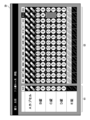
- FIG. 11 is a diagram showing an example of a display image of the inspection result.
- the figure shows an example of the test results for 14 packages. Further, an example is shown in which five drugs (A capsule, B tablet, C tablet, D tablet, E tablet) are enclosed in each packet, and an example in which the E tablet is a transparent drug is shown. ing.
- the display image ID of the test result includes the name of the prescribed drug, the master image of the prescribed drug, the image of the drug enclosed in each package (individual drug image), and each package.
- the inspection result of is displayed.
- the name of the prescribed drug and its master image are displayed in the prescription drug information display column C1.
- the names of the drugs are displayed in a vertical line in the prescription drug information display column C1.
- the master image of that drug is displayed in the column to the right.
- the upper image is the front image and the lower image is the back image.
- the image of the drug enclosed in each packet and the test result are displayed in the test result display column C2.
- the images of the drugs encapsulated in each packet are displayed side by side in a vertical row. Therefore, the images displayed in the same column show images of the drugs encapsulated in the same drug package. Further, the images of each drug are displayed in the same order as the names of the drugs displayed in the prescription drug information display field C1. Therefore, the image displayed on the same line as the name of the drug displayed in the prescription drug information display column C1 indicates the image of the drug having that name. Since the master image is displayed on the same line, visual inspection can be easily performed.
- a number indicating the inspection order (image shooting order) of each medicine package is attached. This number is used to display the test results. Specifically, if the drug is not enclosed (packaged) according to the prescription, the number of the drug is reversed and displayed. That is, the characters and the background color are displayed in reverse. For example, if the drug is encapsulated according to the prescription, the number will be displayed in black letters on a white background (so-called blackout display). On the other hand, if the drug is not enclosed according to the prescription, the number is displayed in white letters on a black background (so-called white display).
- FIG. 11 shows an example in which the thirteenth medicine package (display number “013”) is different from the prescription. The thirteenth medicine package lacks C tablets. In this case, the individual drug image of C tablet is not displayed for the 13th drug package. Therefore, by confirming the display of the individual drug image, the deficient drug can be recognized.
- the image of each drug displayed in the test result display column C2 is an individual drug image generated by cutting out from the photographed image. However, if it is displayed as it is, the visibility of the drug may be poor. Therefore, when there is an individual drug image determined by the visibility determination unit 32H to have poor visibility, the display image generation unit 32J replaces the image with the image processed by the image processing unit 32I and displays the image. To generate. As a result, the confirmation work when visually confirming the individual drug image can be facilitated.
- the display control unit 32K controls the display on the display device 36.
- the display control unit 32K causes the display device 36 to display the generated display image.
- FIG. 12 is a flowchart showing a procedure for testing a drug using a drug test support system.
- the prescription information of the drug to be tested is input to the drug test support device 30 (step S10).
- the prescription information is input from the prescription information input device 20 to the drug test support device 30.
- the drug test support device 30 acquires the input prescription information.
- the drug test support device 30 acquires a master image of the drug included in the prescription from the drug DB based on the acquired prescription information (step S11).
- the imaging device 10 photographs the drug to be inspected (step S12).
- Photography is performed by photographing the medicine package.
- the drug enclosed in the drug package that is, the packaged drug is photographed.
- the photographed image of the drug package (image of the packaged drug) is output to the drug test support device 30.
- the drug test support device 30 acquires a photographed image (first photographed image) of the medicine package output from the photographing device 10 (step S13).
- the drug test support device 30 extracts an image of an individual drug (individual drug image) from the acquired image of the drug package (photographed image of the packaged drug) (step S14). Extraction is performed by detecting a drug from an image and cutting out the detected drug.
- the drug test support device 30 collates the extracted individual drug image with the master image (step S15). After the collation, the drug test support device 30 determines the test result based on the collation result (step S16). That is, it is determined whether or not the drug (packaged drug) enclosed in the drug package to be inspected is packaged according to the prescription.
- the drug test support device 30 performs a process of improving the visibility of the individual drug image having poor visibility after extracting the individual drug image (step S20).
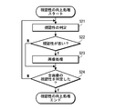
- FIG. 13 is a flowchart showing the procedure of the process for improving the visibility of the individual drug image.
- a process of determining the visibility of the individual drug image is performed (step S21).
- the quality of visibility is determined based on the difference between the pixel value of the drug region and the pixel value of the non-drug region of the individual drug image.
- step S22 it is determined whether or not the determined result is bad.
- the determination result is bad, that is, when the visibility is poor, image processing for improving the visibility is performed (step S23).
- the judgment result is good, that is, if the visibility is good, the image processing is not performed and the image is used as it is for display.
- the process of improving the visibility of the individual drug image first, the quality of the visibility of the image is determined, and the image processing for improving the visibility is performed only for the image determined to have poor visibility. Be given. This process is performed on all the extracted individual drug images. Therefore, it is determined whether or not the determination of all the individual drug images is completed (step S24). When the determination of all the individual drug images is completed, the process of improving the visibility of the individual drug images is completed.
- the drug test support device 30 when the visibility improvement process and the test result determination process are completed, the drug test support device 30 generates a display image showing the test result (step S17). The drug test support device 30 displays the generated display image on the display device 36 (step S18).
- the display image of the test result includes the name of the prescribed drug, the master image of the prescribed drug, the image of the drug enclosed in each package (individual drug image), and the inspection of each package. The result is displayed.
- the processed image is displayed. That is, the image is not cut out as it is from the captured image, but is replaced with the processed image and displayed. Since the visibility of the drug in the processed image is improved, the visual confirmation work can be facilitated.
- the visibility is improved as necessary when displaying the image of the photographed drug. This makes it possible to reduce the visual inspection of the drug.
- the individual drug image having poor visibility is subjected to image processing to improve the visibility.
- the image is replaced with an image taken under different conditions to improve the visibility. Specifically, the image is replaced with an image taken under conditions of different background colors to improve visibility.
- the imaging device is configured so that the drug can be imaged under conditions of different background colors.
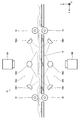
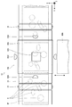
- 14 and 15 are a plan view and a side view showing a schematic configuration of the photographing apparatus of the present embodiment, respectively.
- the imaging device 10 of the present embodiment is different from the imaging device of the first embodiment in that it includes the first imaging plate 40A and the second imaging plate 40B. Therefore, here, only the configurations and functions of the first photographing plate 40A and the second photographing plate 40B will be described.
- the first photographing plate 40A and the second photographing plate 40B are composed of white plates.
- the first photographing plate 40A and the second photographing plate 40B are arranged above and below the stage 14 and are arranged in parallel with the stage 14, respectively.
- the first photographing plate 40A is arranged on the side of the first camera 12A
- the second photographing plate 40B is arranged on the side of the second camera 12B.
- the first photographing plate 40A and the second photographing plate 40B are each driven by a drive mechanism (not shown) and slide horizontally between the photographing position and the retracted position.
- the first photographing plate 40A moves directly above the stage 14 by moving to the photographing position (see FIG. 14).
- the upper surface (surface) of the medicine package placed on the stage 14 is covered with the first photographing plate 40A.
- the first photographing plate 40A moves to a position outside the stage by moving to the retracted position.
- the second photographing plate 40B moves directly below the stage 14 by moving to the photographing position.
- the lower surface (back surface) of the medicine package placed on the stage 14 is covered with the second photographing plate 40B.
- the second photographing plate 40B moves to a position outside the stage by moving to the retracted position.
- the first surface (front surface) and the second surface (back surface) of the medicine package TP are photographed with the first imaging plate 40A and the second imaging plate 40B retracted to the retracted positions.
- the first surface of the medicine package TP is photographed by the first camera 12A, and is photographed by causing the first lighting device 16A to emit light.
- the second surface of the medicine package TP is photographed by the second camera 12B, and is photographed by causing the second lighting device 16B to emit light.
- the second imaging plate 40B is positioned at the imaging position, and the first surface of the medicine package TP is photographed.
- the photographing is performed by using the first camera 12A, and the first lighting device 16A is made to emit light to be photographed.
- the second shooting plate 40B is retracted to the retracted position.
- the first imaging plate 40A is positioned at the imaging position, and the second surface of the medicine package TP is photographed.
- the photographing is performed by using the second camera 12B, and the second lighting device 16B is made to emit light to be photographed.
- the second shooting plate 40B is retracted to the retracted position.
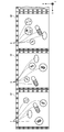
- FIG. 16 is a diagram showing an example of an image obtained by shooting.
- FIGS. (A) and (B) are diagrams showing an example of a photographed image obtained when the first photographing plate 40A and the second photographing plate 40B are retracted and photographed.
- FIG. (A) shows an example of a photographed image ITP1 obtained when the first surface of the medicine package is photographed.
- FIG. (B) shows an example of a photographed image ITP2 obtained when the second surface of the medicine package is photographed.
- FIGS. (A) and (B) when the first imaging plate 40A and the second imaging plate 40B are retracted and photographed, each drug is imaged on a black background.
- the captured images ITP1 and ITP2 are examples of the first captured images.
- FIGS. (C) and (D) are diagrams showing an example of a photographed image obtained when the first photographing plate 40A and the second photographing plate 40B are inserted and photographed.
- FIG. (C) shows an example of a photographed image ITP3 obtained when the second photographing plate 40B is inserted and the first surface of the medicine package is photographed.
- FIG. (D) shows an example of a photographed image ITP4 obtained when the first photographing plate 40A is inserted and the second surface of the medicine package is photographed.
- FIGS. (C) and (D) when the first imaging plate 40A and the second imaging plate 40B are inserted and photographed, each drug is photographed on a white (or gray) background.
- the captured images ITP3 and ITP4 are examples of the second captured images.
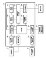
- FIG. 17 is a block diagram of a function realized by the processing device of the drug test support device of the present embodiment.
- the processing device 32 of the drug test support device of the present embodiment has the function of the image switching unit 32L instead of the image processing unit 32I (see FIG. 6). It is different from the processing device 32.
- the basic operation of the processing device 32 is the same as that of the first embodiment, and the individual drug image extracted from the photographed image (first photographed image) on the black background is used for collation with the master image. ..
- an individual drug image extracted from a photographed image on a black background is used.
- an individual drug image extracted from a photographed image (second photographed image) on a white background is used.
- the image switching unit 32L switches the individual drug image used for displaying the test result based on the determination result of the visibility determination unit 32H. Specifically, when the visibility of the individual drug image cut out from the photographed image on the black background is poor, the individual drug image cut out from the photographed image on the white background is switched to. The cutting process is performed by the individual drug image extraction unit 32C. At this time, for the detection of the drug, the result of the detection performed on the captured image on the black background can be used.
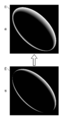
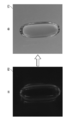
- FIG. 18 is a diagram schematically showing an example of image switching.
- FIG. (A) schematically shows an individual drug image IT2 extracted from a photographed image on a black background.
- FIG. 3B schematically shows an individual drug image IT3 extracted from a photographed image on a white background. As shown in the figure, visibility can be improved by switching to an image having a different background color.
- the display image generation unit 32J When the image is switched, the display image generation unit 32J generates a display image of the inspection result using the image after the switching.
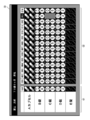
- FIG. 19 is a diagram showing an example of a display image of the inspection result. The figure shows an example in which the image of the E lock is replaced with the image of the white background and displayed.
- the individual drug image cut out from the photographed image on the black background is poor, the individual drug image cut out from the photographed image on the white background is replaced and displayed.
- the visibility of the drug can be improved.
- FIG. 20 is a diagram showing an example of a display image when the display is switched only on one side.
- the image on one side (first side) is switched to the image on a white background. In this way, visual inspection can be easily performed simply by switching the image on one side.
- the shooting plates When shooting with the background color changed only on one side, the shooting plates (first shooting plate 40A and second shooting board 40B) may be provided on at least one of them.
- images having different background colors are photographed by inserting white photographing plates (first photographing plate 40A and second photographing plate 40B), but the background colors are different.
- the method of taking an image is not limited to this. In particular, the position where the photographing plate is inserted, the lighting conditions, and the like can be changed as appropriate.
- [Other embodiments] [Modified example of visibility judgment method]
- the visibility of the photographed image is mainly determined by the color (including transparency) of the drug.
- the color of the drug can be specified by the type of drug. Therefore, if the type of drug can be specified in advance, the visibility of the drug can be estimated. For example, in the case of a transparent drug, visibility deteriorates when the image is taken under the condition that the background becomes black. Similarly, for a drug having a color similar to the background color of the obtained image, the visibility is reduced.
- the type of drug can be identified from the prescription information. For a drug to be dispensed based on prescription information, it is possible to determine (estimate) whether or not the visibility of the individual drug image is good or bad by acquiring the prescription information.
- FIG. 21 is a block diagram showing an example of a function realized by the processing device when determining the visibility of an individual drug image based on prescription information.
- the processing device 32 realizes the function of the color information acquisition unit 32M.
- the color information acquisition unit 32M acquires the color information of the drug to be inspected from the drug DB based on the prescription information acquired by the prescription information acquisition unit 32D.
- the visibility determination unit 32H determines the visibility of the individually captured image based on the color information acquired by the color information acquisition unit 32M. For example, when a drug is photographed under the condition that the background becomes black, if the color of the acquired drug is transparent or translucent, the individual drug image of the drug is determined to have poor visibility of the drug. Similarly, when the color of the acquired drug is black (black, brown, etc.), it is determined that the individual drug image of the drug has poor visibility of the drug.
- the visibility determination unit 32H determines that the visibility is poor, a process for improving the visibility is performed. That is, image processing is performed on the individual drug image of the drug determined to have poor visibility, and the visibility is improved. Alternatively, the visibility is improved by switching to an image having good visibility (an image taken under conditions of different background colors).
- FIG. 22 is a diagram showing an example of a drug DB. As shown in the figure, the color information (color information) of the drug is stored in association with the name of the drug (and the master image). Therefore, if the name of the drug is specified, the color of the drug is specified.
- the color information of the drug is stored in the drug DB, and the quality of visibility is determined based on the color information of the drug acquired from the drug DB.
- the quality may be stored directly in the drug DB. In this case, the quality of visibility can be directly determined from the type (name) of the drug.
- the RGB image when judging the quality of visibility from the photographed image of the drug, when judging by comparing the pixel values of the images, the RGB image may be compared or the single channel may be compared. Moreover, Lab image, hsv image, lc conversion and the like can also be used.
- both the front and back sides of the drug are photographed, but it is also possible to photograph only one side.
- the image to be displayed is only one side.
- the above embodiment when displaying an individual drug image of a drug having poor visibility, it is configured to display after image processing with improved visibility, but before image processing according to an instruction from the user. It may be possible to switch to the display of the image of. That is, the display of the image before image processing (so-called original image) and the display of the image after image processing may be arbitrarily switched. In this case, for example, a switching button is displayed on the screen, and the display can be switched by pressing (clicking) the switching button. The same applies when replacing the image with an image having improved visibility.
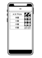
- FIG. 23 is a diagram showing another example of displaying an image of the drug.
- the figure shows an example of displaying a photographed image of a drug on a smartphone.
- the figure shows an example of displaying a photographed image of a packaged drug on a smartphone.
- the image of each drug (individual drug image) is generated by cutting out the image of the drug package.
- the figure shows an example when it is determined that the visibility of the individual drug image of the E tablet is poor, and the image is replaced with an image with good visibility (an image taken under conditions of different background colors).
- An example of the case is shown.
- the smartphone display is an example of a display device.
- the processing device that constitutes the drug test support device can be configured to include various processors as shown below.
- various processors include programmable logic devices (PLDs) and ASICs, which are processors whose circuit configurations can be changed after manufacturing FPGAs (Field Programmable Gate Arrays) and the like. It includes a dedicated electric circuit, which is a processor having a circuit configuration specially designed to execute a specific process such as Application Specific Integrated Circuit).
- the function of the processing device may be realized by one of these various processors, or may be realized by two or more processors of the same type or different types (for example, a plurality of FPGAs or a combination of a CPU and an FPGA). good.
- a plurality of functions may be realized by one processor.
- one IC (integrated circuit) chip can combine the functions of the entire system including multiple functions, as typified by System On Chip (SoC).
- SoC System On Chip
- various functions are realized by using one or more of the above-mentioned various processors as a hardware structure. Further, the hardware structure of these various processors is, more specifically, an electric circuit in which circuit elements such as semiconductor elements are combined.
- the code of the program to be executed is stored in a ROM and / or a non-temporary recording medium such as a flash ROM, and the processor refers to the software.
- the software stored in the non-temporary recording medium includes a program for executing the drug test support method according to the present invention.
- the code may be recorded on a non-temporary recording medium such as various optical magnetic recording devices or semiconductor memories instead of the ROM.
- VRAM Video RAM
- SDRAM Synchronous Dynamic Random Access Memory
- EEPROM Electrically Erasable and Programmable Read Only
- Drug inspection support system 10 Imaging device 12A 1st camera 12B 2nd camera 14 Stage 16A 1st lighting device 16A1 Light emitting unit 16B 2nd lighting device 16B1 Light emitting unit 18 Roller 20 Prescription information input device 30 Drug test support device 32 Processing device 32A Imaging control unit 32B Imaging image acquisition unit 32C Individual drug image extraction unit 32D Prescription information acquisition unit 32E Master image acquisition unit 32F Verification unit 32G Inspection result determination unit 32H Visibility determination unit 32I Image processing unit 32J Display image generation unit 32K Display control unit 32L Image switching unit 32M Color information acquisition unit 34 Operation device 36 Display device 38 Storage device 40A 1st imaging board 40B 2nd imaging plate C1 Prescription drug information display column C2 Inspection result display column F frame FD Detection frame IT Individual drug image IT0 Individual Drug image IT1 Individual drug image IT2 Individual drug image IT3 Individual drug image ITP Photographed image ITP1 Photographed image ITP2 Photographed image ITP3 Photographed image ITP4 Photographed image T Drug TP Drug package S10 to S18 Drug
Landscapes
- Engineering & Computer Science (AREA)
- Physics & Mathematics (AREA)
- General Physics & Mathematics (AREA)
- Theoretical Computer Science (AREA)
- Multimedia (AREA)
- Quality & Reliability (AREA)
- Medical Preparation Storing Or Oral Administration Devices (AREA)
- Image Processing (AREA)
Priority Applications (4)
| Application Number | Priority Date | Filing Date | Title |
|---|---|---|---|
| CN202180007488.9A CN114845682A (zh) | 2020-01-17 | 2021-01-07 | 图像处理装置和方法 |
| EP21740655.2A EP4091598A1 (en) | 2020-01-17 | 2021-01-07 | Image processing apparatus and method |
| JP2021571162A JP7375049B2 (ja) | 2020-01-17 | 2021-01-07 | 画像処理装置及び方法 |
| US17/859,393 US20220343643A1 (en) | 2020-01-17 | 2022-07-07 | Image processing apparatus and method |
Applications Claiming Priority (2)
| Application Number | Priority Date | Filing Date | Title |
|---|---|---|---|
| JP2020-006079 | 2020-01-17 | ||
| JP2020006079 | 2020-01-17 |
Related Child Applications (1)
| Application Number | Title | Priority Date | Filing Date |
|---|---|---|---|
| US17/859,393 Continuation US20220343643A1 (en) | 2020-01-17 | 2022-07-07 | Image processing apparatus and method |
Publications (1)
| Publication Number | Publication Date |
|---|---|
| WO2021145266A1 true WO2021145266A1 (ja) | 2021-07-22 |
Family
ID=76864625
Family Applications (1)
| Application Number | Title | Priority Date | Filing Date |
|---|---|---|---|
| PCT/JP2021/000328 Ceased WO2021145266A1 (ja) | 2020-01-17 | 2021-01-07 | 画像処理装置及び方法 |
Country Status (5)
| Country | Link |
|---|---|
| US (1) | US20220343643A1 (https=) |
| EP (1) | EP4091598A1 (https=) |
| JP (1) | JP7375049B2 (https=) |
| CN (1) | CN114845682A (https=) |
| WO (1) | WO2021145266A1 (https=) |
Families Citing this family (1)
| Publication number | Priority date | Publication date | Assignee | Title |
|---|---|---|---|---|
| JP7752597B2 (ja) * | 2022-12-26 | 2025-10-10 | 富士フイルムメディカル株式会社 | 薬剤識別装置、薬剤識別方法及びプログラム |
Citations (4)
| Publication number | Priority date | Publication date | Assignee | Title |
|---|---|---|---|---|
| WO2016047569A1 (ja) | 2014-09-25 | 2016-03-31 | 株式会社湯山製作所 | 鑑査支援システム、錠剤分包装置 |
| WO2018034100A1 (ja) * | 2016-08-17 | 2018-02-22 | 富士フイルム株式会社 | 調剤監査装置、及び方法 |
| WO2018221065A1 (ja) * | 2017-05-30 | 2018-12-06 | 富士フイルム株式会社 | 薬剤検査支援装置及び薬剤検査支援方法 |
| WO2019193912A1 (ja) * | 2018-04-03 | 2019-10-10 | 富士フイルム富山化学株式会社 | 薬剤判定装置及び薬剤判定方法 |
Family Cites Families (2)
| Publication number | Priority date | Publication date | Assignee | Title |
|---|---|---|---|---|
| CN103238166A (zh) * | 2011-02-14 | 2013-08-07 | 株式会社汤山制作所 | 配药确认装置 |
| JP6077947B2 (ja) * | 2013-06-19 | 2017-02-08 | 富士フイルム株式会社 | 薬剤情報取得装置及び方法 |
-
2021
- 2021-01-07 CN CN202180007488.9A patent/CN114845682A/zh active Pending
- 2021-01-07 JP JP2021571162A patent/JP7375049B2/ja active Active
- 2021-01-07 WO PCT/JP2021/000328 patent/WO2021145266A1/ja not_active Ceased
- 2021-01-07 EP EP21740655.2A patent/EP4091598A1/en not_active Withdrawn
-
2022
- 2022-07-07 US US17/859,393 patent/US20220343643A1/en not_active Abandoned
Patent Citations (4)
| Publication number | Priority date | Publication date | Assignee | Title |
|---|---|---|---|---|
| WO2016047569A1 (ja) | 2014-09-25 | 2016-03-31 | 株式会社湯山製作所 | 鑑査支援システム、錠剤分包装置 |
| WO2018034100A1 (ja) * | 2016-08-17 | 2018-02-22 | 富士フイルム株式会社 | 調剤監査装置、及び方法 |
| WO2018221065A1 (ja) * | 2017-05-30 | 2018-12-06 | 富士フイルム株式会社 | 薬剤検査支援装置及び薬剤検査支援方法 |
| WO2019193912A1 (ja) * | 2018-04-03 | 2019-10-10 | 富士フイルム富山化学株式会社 | 薬剤判定装置及び薬剤判定方法 |
Also Published As
| Publication number | Publication date |
|---|---|
| JP7375049B2 (ja) | 2023-11-07 |
| EP4091598A1 (en) | 2022-11-23 |
| US20220343643A1 (en) | 2022-10-27 |
| JPWO2021145266A1 (https=) | 2021-07-22 |
| CN114845682A (zh) | 2022-08-02 |
Similar Documents
| Publication | Publication Date | Title |
|---|---|---|
| CN104176334B (zh) | 药剂检查装置 | |
| US10892048B2 (en) | Machine learning pill identification | |
| EP3109623B1 (en) | Medicine packet inspection apparatus and method | |
| US10565545B2 (en) | Drug inspection support apparatus and method | |
| JP5351980B2 (ja) | 錠剤監査支援方法及び錠剤監査支援装置 | |
| CN108475145B (zh) | 图像识别装置、图像识别方法以及图像识别单元 | |
| CN102117442B (zh) | 药物管理系统和使用该系统的方法 | |
| WO2015046044A1 (ja) | 薬剤認識装置及び方法 | |
| JP6894977B2 (ja) | 薬剤検査支援装置、薬剤検査支援方法、薬剤識別装置、薬剤識別方法及びプログラム、記録媒体 | |
| JP6853891B2 (ja) | 薬剤監査装置、画像処理装置、画像処理方法及びプログラム | |
| US10489647B2 (en) | Method for computing a unique identifier for a gemstone having facets | |
| CN111052145B (zh) | 药剂检查辅助装置、图像处理装置、图像处理方法 | |
| US20200175318A1 (en) | Medicine inspection support device, image processing device, image processing method, and program | |
| WO2013129099A1 (ja) | 薬剤個数計数装置 | |
| JP7375049B2 (ja) | 画像処理装置及び方法 | |
| JP7437259B2 (ja) | 画像処理装置、薬剤識別装置、画像処理方法及び薬剤識別方法 | |
| US20230206585A1 (en) | Drug list display method and drug list | |
| JP7374869B2 (ja) | 薬剤候補表示方法及びプログラム、薬剤識別装置、薬剤識別システム | |
| JP7338030B2 (ja) | 物体認識装置、方法及びプログラム | |
| CN112580388A (zh) | 指纹识别模组及其扫描方法、存储介质、电子设备 | |
| JP2019037373A (ja) | 医薬品鑑査装置及び医薬品鑑査方法 |
Legal Events
| Date | Code | Title | Description |
|---|---|---|---|
| 121 | Ep: the epo has been informed by wipo that ep was designated in this application |
Ref document number: 21740655 Country of ref document: EP Kind code of ref document: A1 |
|
| ENP | Entry into the national phase |
Ref document number: 2021571162 Country of ref document: JP Kind code of ref document: A |
|
| NENP | Non-entry into the national phase |
Ref country code: DE |
|
| ENP | Entry into the national phase |
Ref document number: 2021740655 Country of ref document: EP Effective date: 20220817 |