WO2021145244A1 - 表示装置、画像生成方法及びプログラム - Google Patents
表示装置、画像生成方法及びプログラム Download PDFInfo
- Publication number
- WO2021145244A1 WO2021145244A1 PCT/JP2021/000159 JP2021000159W WO2021145244A1 WO 2021145244 A1 WO2021145244 A1 WO 2021145244A1 JP 2021000159 W JP2021000159 W JP 2021000159W WO 2021145244 A1 WO2021145244 A1 WO 2021145244A1
- Authority
- WO
- WIPO (PCT)
- Prior art keywords
- image
- display device
- display
- sensor
- photographer
- Prior art date
Links
- 238000000034 method Methods 0.000 title claims abstract description 59
- 238000006243 chemical reaction Methods 0.000 claims description 26
- 230000001131 transforming effect Effects 0.000 claims 1
- 210000001747 pupil Anatomy 0.000 description 22
- 238000004364 calculation method Methods 0.000 description 14
- 238000005516 engineering process Methods 0.000 description 14
- 238000012545 processing Methods 0.000 description 14
- 235000013305 food Nutrition 0.000 description 12
- 238000001514 detection method Methods 0.000 description 8
- 230000000295 complement effect Effects 0.000 description 6
- 238000010586 diagram Methods 0.000 description 6
- 230000004888 barrier function Effects 0.000 description 5
- 125000002066 L-histidyl group Chemical group [H]N1C([H])=NC(C([H])([H])[C@](C(=O)[*])([H])N([H])[H])=C1[H] 0.000 description 4
- 230000003190 augmentative effect Effects 0.000 description 2
- 238000004891 communication Methods 0.000 description 2
- 235000021186 dishes Nutrition 0.000 description 2
- 238000003384 imaging method Methods 0.000 description 2
- 238000007654 immersion Methods 0.000 description 2
- 230000009466 transformation Effects 0.000 description 2
- 241000972773 Aulopiformes Species 0.000 description 1
- 206010020751 Hypersensitivity Diseases 0.000 description 1
- 240000008415 Lactuca sativa Species 0.000 description 1
- 244000294411 Mirabilis expansa Species 0.000 description 1
- 235000015429 Mirabilis expansa Nutrition 0.000 description 1
- 240000007594 Oryza sativa Species 0.000 description 1
- 235000007164 Oryza sativa Nutrition 0.000 description 1
- 208000026935 allergic disease Diseases 0.000 description 1
- 230000007815 allergy Effects 0.000 description 1
- 235000013527 bean curd Nutrition 0.000 description 1
- 238000007796 conventional method Methods 0.000 description 1
- 235000011950 custard Nutrition 0.000 description 1
- 230000009977 dual effect Effects 0.000 description 1
- 238000005401 electroluminescence Methods 0.000 description 1
- 238000003702 image correction Methods 0.000 description 1
- 239000004973 liquid crystal related substance Substances 0.000 description 1
- 238000001459 lithography Methods 0.000 description 1
- 230000004807 localization Effects 0.000 description 1
- 238000013507 mapping Methods 0.000 description 1
- 238000005259 measurement Methods 0.000 description 1
- 235000013536 miso Nutrition 0.000 description 1
- 235000021110 pickles Nutrition 0.000 description 1
- 235000015277 pork Nutrition 0.000 description 1
- 235000011962 puddings Nutrition 0.000 description 1
- 235000009566 rice Nutrition 0.000 description 1
- 235000012045 salad Nutrition 0.000 description 1
- 235000019515 salmon Nutrition 0.000 description 1
- 235000014347 soups Nutrition 0.000 description 1
Images


Classifications
-
- G—PHYSICS
- G09—EDUCATION; CRYPTOGRAPHY; DISPLAY; ADVERTISING; SEALS
- G09G—ARRANGEMENTS OR CIRCUITS FOR CONTROL OF INDICATING DEVICES USING STATIC MEANS TO PRESENT VARIABLE INFORMATION
- G09G5/00—Control arrangements or circuits for visual indicators common to cathode-ray tube indicators and other visual indicators
- G09G5/36—Control arrangements or circuits for visual indicators common to cathode-ray tube indicators and other visual indicators characterised by the display of a graphic pattern, e.g. using an all-points-addressable [APA] memory
- G09G5/37—Details of the operation on graphic patterns
- G09G5/377—Details of the operation on graphic patterns for mixing or overlaying two or more graphic patterns
-
- G—PHYSICS
- G06—COMPUTING; CALCULATING OR COUNTING
- G06V—IMAGE OR VIDEO RECOGNITION OR UNDERSTANDING
- G06V10/00—Arrangements for image or video recognition or understanding
- G06V10/20—Image preprocessing
- G06V10/26—Segmentation of patterns in the image field; Cutting or merging of image elements to establish the pattern region, e.g. clustering-based techniques; Detection of occlusion
-
- G—PHYSICS
- G01—MEASURING; TESTING
- G01B—MEASURING LENGTH, THICKNESS OR SIMILAR LINEAR DIMENSIONS; MEASURING ANGLES; MEASURING AREAS; MEASURING IRREGULARITIES OF SURFACES OR CONTOURS
- G01B11/00—Measuring arrangements characterised by the use of optical techniques
-
- G—PHYSICS
- G06—COMPUTING; CALCULATING OR COUNTING
- G06F—ELECTRIC DIGITAL DATA PROCESSING
- G06F1/00—Details not covered by groups G06F3/00 - G06F13/00 and G06F21/00
- G06F1/16—Constructional details or arrangements
- G06F1/1613—Constructional details or arrangements for portable computers
- G06F1/1626—Constructional details or arrangements for portable computers with a single-body enclosure integrating a flat display, e.g. Personal Digital Assistants [PDAs]
-
- G—PHYSICS
- G06—COMPUTING; CALCULATING OR COUNTING
- G06F—ELECTRIC DIGITAL DATA PROCESSING
- G06F3/00—Input arrangements for transferring data to be processed into a form capable of being handled by the computer; Output arrangements for transferring data from processing unit to output unit, e.g. interface arrangements
- G06F3/01—Input arrangements or combined input and output arrangements for interaction between user and computer
- G06F3/011—Arrangements for interaction with the human body, e.g. for user immersion in virtual reality
- G06F3/013—Eye tracking input arrangements
-
- G—PHYSICS
- G06—COMPUTING; CALCULATING OR COUNTING
- G06F—ELECTRIC DIGITAL DATA PROCESSING
- G06F3/00—Input arrangements for transferring data to be processed into a form capable of being handled by the computer; Output arrangements for transferring data from processing unit to output unit, e.g. interface arrangements
- G06F3/01—Input arrangements or combined input and output arrangements for interaction between user and computer
- G06F3/048—Interaction techniques based on graphical user interfaces [GUI]
- G06F3/0481—Interaction techniques based on graphical user interfaces [GUI] based on specific properties of the displayed interaction object or a metaphor-based environment, e.g. interaction with desktop elements like windows or icons, or assisted by a cursor's changing behaviour or appearance
- G06F3/04815—Interaction with a metaphor-based environment or interaction object displayed as three-dimensional, e.g. changing the user viewpoint with respect to the environment or object
-
- G—PHYSICS
- G06—COMPUTING; CALCULATING OR COUNTING
- G06F—ELECTRIC DIGITAL DATA PROCESSING
- G06F3/00—Input arrangements for transferring data to be processed into a form capable of being handled by the computer; Output arrangements for transferring data from processing unit to output unit, e.g. interface arrangements
- G06F3/01—Input arrangements or combined input and output arrangements for interaction between user and computer
- G06F3/048—Interaction techniques based on graphical user interfaces [GUI]
- G06F3/0481—Interaction techniques based on graphical user interfaces [GUI] based on specific properties of the displayed interaction object or a metaphor-based environment, e.g. interaction with desktop elements like windows or icons, or assisted by a cursor's changing behaviour or appearance
- G06F3/0482—Interaction with lists of selectable items, e.g. menus
-
- G—PHYSICS
- G06—COMPUTING; CALCULATING OR COUNTING
- G06F—ELECTRIC DIGITAL DATA PROCESSING
- G06F3/00—Input arrangements for transferring data to be processed into a form capable of being handled by the computer; Output arrangements for transferring data from processing unit to output unit, e.g. interface arrangements
- G06F3/01—Input arrangements or combined input and output arrangements for interaction between user and computer
- G06F3/048—Interaction techniques based on graphical user interfaces [GUI]
- G06F3/0484—Interaction techniques based on graphical user interfaces [GUI] for the control of specific functions or operations, e.g. selecting or manipulating an object, an image or a displayed text element, setting a parameter value or selecting a range
- G06F3/04842—Selection of displayed objects or displayed text elements
-
- G—PHYSICS
- G06—COMPUTING; CALCULATING OR COUNTING
- G06F—ELECTRIC DIGITAL DATA PROCESSING
- G06F3/00—Input arrangements for transferring data to be processed into a form capable of being handled by the computer; Output arrangements for transferring data from processing unit to output unit, e.g. interface arrangements
- G06F3/01—Input arrangements or combined input and output arrangements for interaction between user and computer
- G06F3/048—Interaction techniques based on graphical user interfaces [GUI]
- G06F3/0487—Interaction techniques based on graphical user interfaces [GUI] using specific features provided by the input device, e.g. functions controlled by the rotation of a mouse with dual sensing arrangements, or of the nature of the input device, e.g. tap gestures based on pressure sensed by a digitiser
- G06F3/0488—Interaction techniques based on graphical user interfaces [GUI] using specific features provided by the input device, e.g. functions controlled by the rotation of a mouse with dual sensing arrangements, or of the nature of the input device, e.g. tap gestures based on pressure sensed by a digitiser using a touch-screen or digitiser, e.g. input of commands through traced gestures
-
- G—PHYSICS
- G06—COMPUTING; CALCULATING OR COUNTING
- G06F—ELECTRIC DIGITAL DATA PROCESSING
- G06F3/00—Input arrangements for transferring data to be processed into a form capable of being handled by the computer; Output arrangements for transferring data from processing unit to output unit, e.g. interface arrangements
- G06F3/14—Digital output to display device ; Cooperation and interconnection of the display device with other functional units
-
- G—PHYSICS
- G06—COMPUTING; CALCULATING OR COUNTING
- G06T—IMAGE DATA PROCESSING OR GENERATION, IN GENERAL
- G06T19/00—Manipulating 3D models or images for computer graphics
-
- G—PHYSICS
- G06—COMPUTING; CALCULATING OR COUNTING
- G06T—IMAGE DATA PROCESSING OR GENERATION, IN GENERAL
- G06T5/00—Image enhancement or restoration
- G06T5/50—Image enhancement or restoration using two or more images, e.g. averaging or subtraction
-
- G—PHYSICS
- G06—COMPUTING; CALCULATING OR COUNTING
- G06T—IMAGE DATA PROCESSING OR GENERATION, IN GENERAL
- G06T5/00—Image enhancement or restoration
- G06T5/77—Retouching; Inpainting; Scratch removal
-
- G—PHYSICS
- G06—COMPUTING; CALCULATING OR COUNTING
- G06T—IMAGE DATA PROCESSING OR GENERATION, IN GENERAL
- G06T5/00—Image enhancement or restoration
- G06T5/80—Geometric correction
-
- G—PHYSICS
- G06—COMPUTING; CALCULATING OR COUNTING
- G06T—IMAGE DATA PROCESSING OR GENERATION, IN GENERAL
- G06T7/00—Image analysis
- G06T7/70—Determining position or orientation of objects or cameras
-
- G—PHYSICS
- G06—COMPUTING; CALCULATING OR COUNTING
- G06V—IMAGE OR VIDEO RECOGNITION OR UNDERSTANDING
- G06V10/00—Arrangements for image or video recognition or understanding
- G06V10/70—Arrangements for image or video recognition or understanding using pattern recognition or machine learning
- G06V10/74—Image or video pattern matching; Proximity measures in feature spaces
- G06V10/761—Proximity, similarity or dissimilarity measures
-
- G—PHYSICS
- G06—COMPUTING; CALCULATING OR COUNTING
- G06V—IMAGE OR VIDEO RECOGNITION OR UNDERSTANDING
- G06V20/00—Scenes; Scene-specific elements
- G06V20/20—Scenes; Scene-specific elements in augmented reality scenes
-
- H—ELECTRICITY
- H04—ELECTRIC COMMUNICATION TECHNIQUE
- H04N—PICTORIAL COMMUNICATION, e.g. TELEVISION
- H04N13/00—Stereoscopic video systems; Multi-view video systems; Details thereof
- H04N13/30—Image reproducers
- H04N13/302—Image reproducers for viewing without the aid of special glasses, i.e. using autostereoscopic displays
- H04N13/31—Image reproducers for viewing without the aid of special glasses, i.e. using autostereoscopic displays using parallax barriers
-
- H—ELECTRICITY
- H04—ELECTRIC COMMUNICATION TECHNIQUE
- H04N—PICTORIAL COMMUNICATION, e.g. TELEVISION
- H04N13/00—Stereoscopic video systems; Multi-view video systems; Details thereof
- H04N13/30—Image reproducers
- H04N13/366—Image reproducers using viewer tracking
-
- H—ELECTRICITY
- H04—ELECTRIC COMMUNICATION TECHNIQUE
- H04N—PICTORIAL COMMUNICATION, e.g. TELEVISION
- H04N23/00—Cameras or camera modules comprising electronic image sensors; Control thereof
- H04N23/57—Mechanical or electrical details of cameras or camera modules specially adapted for being embedded in other devices
-
- H—ELECTRICITY
- H04—ELECTRIC COMMUNICATION TECHNIQUE
- H04N—PICTORIAL COMMUNICATION, e.g. TELEVISION
- H04N5/00—Details of television systems
- H04N5/222—Studio circuitry; Studio devices; Studio equipment
- H04N5/262—Studio circuits, e.g. for mixing, switching-over, change of character of image, other special effects ; Cameras specially adapted for the electronic generation of special effects
- H04N5/265—Mixing
-
- H—ELECTRICITY
- H04—ELECTRIC COMMUNICATION TECHNIQUE
- H04N—PICTORIAL COMMUNICATION, e.g. TELEVISION
- H04N5/00—Details of television systems
- H04N5/222—Studio circuitry; Studio devices; Studio equipment
- H04N5/262—Studio circuits, e.g. for mixing, switching-over, change of character of image, other special effects ; Cameras specially adapted for the electronic generation of special effects
- H04N5/272—Means for inserting a foreground image in a background image, i.e. inlay, outlay
-
- H—ELECTRICITY
- H04—ELECTRIC COMMUNICATION TECHNIQUE
- H04N—PICTORIAL COMMUNICATION, e.g. TELEVISION
- H04N5/00—Details of television systems
- H04N5/66—Transforming electric information into light information
-
- G—PHYSICS
- G06—COMPUTING; CALCULATING OR COUNTING
- G06T—IMAGE DATA PROCESSING OR GENERATION, IN GENERAL
- G06T2207/00—Indexing scheme for image analysis or image enhancement
- G06T2207/10—Image acquisition modality
- G06T2207/10028—Range image; Depth image; 3D point clouds
-
- G—PHYSICS
- G06—COMPUTING; CALCULATING OR COUNTING
- G06T—IMAGE DATA PROCESSING OR GENERATION, IN GENERAL
- G06T2207/00—Indexing scheme for image analysis or image enhancement
- G06T2207/20—Special algorithmic details
- G06T2207/20212—Image combination
- G06T2207/20221—Image fusion; Image merging
-
- G—PHYSICS
- G09—EDUCATION; CRYPTOGRAPHY; DISPLAY; ADVERTISING; SEALS
- G09G—ARRANGEMENTS OR CIRCUITS FOR CONTROL OF INDICATING DEVICES USING STATIC MEANS TO PRESENT VARIABLE INFORMATION
- G09G2340/00—Aspects of display data processing
- G09G2340/10—Mixing of images, i.e. displayed pixel being the result of an operation, e.g. adding, on the corresponding input pixels
-
- G—PHYSICS
- G09—EDUCATION; CRYPTOGRAPHY; DISPLAY; ADVERTISING; SEALS
- G09G—ARRANGEMENTS OR CIRCUITS FOR CONTROL OF INDICATING DEVICES USING STATIC MEANS TO PRESENT VARIABLE INFORMATION
- G09G2340/00—Aspects of display data processing
- G09G2340/12—Overlay of images, i.e. displayed pixel being the result of switching between the corresponding input pixels
Definitions
- This technology relates to display devices, image generation methods and programs.
- Mobile devices with a display unit such as mobile phones such as smartphones and tablet terminals, are widespread.
- a mobile device equipped with a camera an image taken by the camera can be displayed on a display unit, and augmented reality (AR) information can be presented by superimposing the image on the display unit.
- AR augmented reality
- the photographer is provided with a highly immersive and immersive AR experience. ..
- Patent Document 1 discloses a technique in which the landscape on the other side of the device changes and is displayed according to the viewpoint position of the user.
- Patent Document 1 describes a technique for improving the presence of remote communication, and displays different images in various directions by using a special display panel in which a display element and an image sensor are embedded. It is described that the object can be photographed from various directions at the same time.
- the displayed image is visually recognized like a miniature garden in the display device.
- the purpose of the present technology is to provide a display device, an image generation method, and a program capable of displaying an image so that the image displayed on the display unit and the scenery outside the display device appear to be connected.
- the display device includes a first image sensor, a first distance sensor, a second sensor, a display unit, and an image generation unit.
- the first image sensor is arranged on the first surface side of the main body of the apparatus.
- the first distance sensor is arranged on the first surface side.
- the second sensor is arranged on the second surface side opposite to the first surface.
- the display unit is arranged on the second surface side.
- the image generation unit is a two-dimensional image of the subject acquired by the first image sensor based on the three-dimensional position information of the photographer's viewpoint calculated based on the sensing result acquired by the second sensor.
- the distance image of the subject acquired by the first distance sensor is used to generate a display image to be displayed on the display unit.
- the image generation method is A first image sensor arranged on the first surface side of the main body of the apparatus, a first distance sensor arranged on the first surface side, and a second surface side opposite to the first surface.
- a two-dimensional image of the subject is acquired from the first image sensor of the display device including the second sensor arranged in the above and the display unit arranged on the second surface side.
- the distance image of the subject is acquired from the first distance sensor, and the distance image is obtained.
- the display image to be displayed on the display unit is generated by using the two-dimensional image and the distance image.
- the program related to this technology A first image sensor arranged on the first surface side of the main body of the apparatus, a first distance sensor arranged on the first surface side, and a second surface side opposite to the first surface.
- An example of a display image of the display device according to the second embodiment is shown, and is a diagram showing a state in which the photographer is holding the display device in his / her hand. It is a figure which shows the display image example of the display device which concerns on 2nd Embodiment, and shows the state which a photographer holds a display device in a hand. It is a figure which shows the display image example displayed by the display device which concerns on 3rd Embodiment. It is a figure explaining the method of detecting the line of sight of a photographer in the method of generating the display image by the display device in 4th Embodiment. It is a figure which shows the display image example displayed by the display device which concerns on 4th Embodiment. It is a figure explaining the method of generating the display image by the display device in 5th Embodiment.
- Display device configuration The present technology can be suitably used for a mobile device such as a mobile phone such as a smartphone having a display unit or a tablet as a display device.
- a display device in the form of a smartphone will be described as an example.
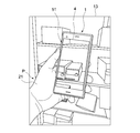
- FIG. 1 is a perspective view for explaining an external shape of a display device according to a first embodiment of the present technology.
- FIG. 1A is a perspective view of the display device viewed from the front side where the display unit is located
- FIG. 1B is a perspective view seen from the back side.
- the display device 1 includes a housing 10, a rear camera 3, a front camera 6 as a second sensor, and a display unit 4.
- the display device 1 is configured by holding a rear camera 3, a front camera 6, a display panel constituting the display unit 4, a drive circuit, various sensors, and the like in a housing 10.
- the main body of the display device 1 has a first surface 2 on the back side and a second surface 5 on the front side located on the opposite side of the first surface 2.
- the first surface 2 and the second surface 5 are in a parallel positional relationship.
- the xyz coordinate directions orthogonal to each other in the figure correspond to the horizontal, vertical, and height of the display device 1 having a substantially rectangular parallelepiped.
- the plane parallel to the first plane 2 is defined as the xy plane, and the thickness direction of the display device 1 corresponding to the height direction is defined as the z-axis.
- An imaging lens 3a of the rear camera 3 is arranged on the first surface 2 side, and the rear camera 3 photographs a subject facing the first surface 2.
- An image pickup lens 6a of the front camera 6 is arranged on the second surface 5 side, and the front camera 6 photographs a subject facing the second surface 5.
- the subject is usually the photographer.
- a display panel constituting the display unit 4 is provided on the second surface 5.
- the display unit 4 is composed of image display means such as a liquid crystal display and an organic EL display (Organic Electro-Luminescence Display).
- the display unit 4 is configured to be capable of displaying an image transmitted / received from an external device through a communication unit (not shown), a button for input operation, an image taken by the front camera 6 and the rear camera 3, and the like. Images include still images and moving images.
- the photographer who is a user who shoots using the display device 1 sees an image displayed on the display unit 4 and performs an input operation or the like from an operation screen displayed on the display unit 4. Therefore, the photographer is located on the second surface 5 side of the display device 1 in order to visually recognize the display unit 4.
- the expression "the other side of the display device 1" may be used, but this indicates the direction seen from the photographer and corresponds to the side of the first surface 2 of the display device 1.
- a subject to be photographed by the rear camera 3 is located on the other side of the display device 1.
- FIG. 2 is a block diagram showing a functional configuration of the display device 1.
- the display device 1 includes a rear camera 3, a front camera 6, an image generation unit 7, a storage unit 8, and a display unit 4.
- both the rear camera 3 and the front camera 6 have an image sensor function and a distance sensor function.
- the image sensor captures a color two-dimensional image of the subject (hereinafter, may be referred to as an RGB two-dimensional image or an RGB image).
- the distance sensor captures a distance image of the subject.
- a ToF (Time of flight) method can be preferably used as the distance sensor, and in the present embodiment, an example in which the ToF type distance sensor is used will be given.
- NIR light near infrared light
- NIR light is used to acquire a distance image having distance information between the distance sensor and the subject.
- the distance image which is the sensing result acquired by the ToF type distance sensor of the front camera 6 as the second sensor, includes not only the distance information but also the two-dimensional position information of the photographer's eyes.
- the rear camera 3 and the front camera 6 are each one imaging device, and an example in which both an RGB image and a distance image can be acquired will be given.
- the RGB image and the distance image may be collectively referred to as an image.
- the rear camera 3 includes an RGB image image sensor 31 that forms a part of the image sensor, a distance image image sensor 32 that forms a part of the distance sensor, and an image pickup processing circuit 33. It has an on-chip lens (not shown), a color filter (not shown), and a light emitting unit (not shown).
- the front camera 6 includes an RGB image image sensor 61 that forms a part of the image sensor, a distance image image sensor 62 that forms a part of the distance sensor, an image pickup processing circuit 63, and an on-chip lens ( It has a color filter (not shown) and a color filter (not shown).
- R pixels and G pixels are formed by providing a color filter between the RGB image image sensor 31 (61) and the distance image image sensor 32 (62) and the on-chip lens.
- B pixels and NIR pixels can be arranged.
- the R pixel is a pixel that obtains a charge corresponding to the light of the red component from the light transmitted through the color filter that transmits the wavelength component of red (R: Red).
- the G pixel is a pixel that obtains a charge corresponding to the light of the green (G) component from the light transmitted through the color filter that transmits the wavelength component of green (G: Green).
- the B pixel is a pixel that obtains a charge corresponding to the light of the blue (B) component from the light transmitted through the color filter that transmits the wavelength component of blue (B: Blue).
- the NIR pixel is a pixel that obtains a charge corresponding to the wavelength band of the NIR light from the light transmitted through the filter that transmits the wavelength component of the near infrared light (NIR light).
- the image pickup processing circuit 33 (63) processes the image pickup signals obtained by the RGB image image sensor 31 (61) and the distance image image sensor 32 (62) to generate an RGB image and a distance image corresponding to the subject. ..
- the on-chip lens is provided for each pixel and collects light from the outside and causes it to enter the color filter of each pixel.
- the light emitting unit that forms part of the distance sensor is used to measure the distance between the camera and the subject.
- the light emitting unit emits NIR light.
- the distance image image sensor 32 (62) receives the return light when the NIR light emitted from the light emitting unit is reflected by the subject.
- the light emitting unit includes, for example, a light emitting member such as a light emitting diode (LED) and a driver circuit for causing the light emitting member to emit light.
- LED light emitting diode
- the display unit 4 displays the display image generated by the image generation unit 7.
- the display unit 4 is configured to be able to display images taken by the rear camera 3 and the front camera 6, respectively. In the following description, an example in which the images taken by the rear camera 3 are displayed on the display unit 4 I will list it.
- the image generation unit 7 includes an image information acquisition unit 70, a viewpoint position calculation unit 71, a coordinate conversion unit 72, and a complement unit 73.
- the image information acquisition unit 70 acquires the RGB image and the distance image of the subject from the rear camera 3, and acquires the RGB image and the distance image of the photographer from the front camera 6.
- the scenery of the image displayed on the display unit 4 and the scenery outside the display device 1 are continuously connected to generate a display image as if the other side of the display device 1 can be seen through. In this case, at least a distance image may be acquired from the front camera 6.
- the viewpoint position calculation unit 71 calculates the three-dimensional position of the photographer's viewpoint based on the distance image taken by the front camera 6.
- the coordinate conversion unit 72 performs coordinate conversion of the image acquired by the rear camera 3 based on the three-dimensional position information of the photographer's viewpoint to generate a display image which is an RGB image viewed from the photographer's viewpoint.
- the complement unit 73 complements the occlusion area to generate a display image displayed on the display unit 4.
- the display image generation method in the image generation unit 7 will be described later.
- FIG. 3 is a diagram showing a state in which the photographer P holds the display device 1 according to the present embodiment in the left hand 21.
- the display unit 4 of the display device 1 displays an image of the other side of the display device 1.
- the image acquired with reference to the rear camera 3 is converted into an image viewed from the viewpoint of the photographer P, and the display image 51 is generated.
- the scenery 13 outside the display device 1 and the scenery of the display image 53 displayed on the display unit 4 of the display device 1 are continuously connected.
- the area blocked by the presence of the display device 1 for the photographer is recognized by the photographer P and displayed on the display unit 4 so that the display device 1 can see through the view on the other side.
- the scenery is no longer like a garden. Therefore, for example, when an image for superimposition such as a virtual object which is Augmented Reality (AR) information is superposed on the image and displayed in AR, the user feels a high immersive feeling and a sense of reality in the world of AR. You can taste it.
- AR Augmented Reality
- the storage unit 8 includes a memory device such as a RAM and a non-volatile recording medium such as a hard disk drive, and causes the display device to execute a process of generating a display image displayed on the display unit 4 of the display device 1.
- the program stored in the recording unit 8 is a step of acquiring an RGB image which is a two-dimensional image of the subject from the rear camera 3 and a distance image of the subject, and a step of acquiring a distance image which is a sensing result of the front camera 6.
- the purpose is to cause the display device to execute the step of generating the display image to be displayed on the display unit 4.
- FIG. 4 is a diagram illustrating an outline of a display image generation method.
- the image of the object 11 to be the subject acquired by the rear camera 3 is an image based on the position of the rear camera 3.
- the image of the object 11 acquired by the rear camera 3 is coordinate-converted so as to be an image viewed from the viewpoint E, and the display image is displayed. To generate. Further, when the display image generated by the coordinate conversion has an occlusion area, the occlusion area is complemented and the display image displayed on the display unit 4 is generated. This will be described below.
- FIG. 5 is a flow chart of a display image generation method.
- the image information acquisition unit 70 acquires the RGB image and the distance image of the subject from the rear camera 3 and the RGB image and the distance image of the photographer from the front camera 6 (ST1).
- the rear camera 3 is calibrated to the rear side
- the front camera 6 is calibrated to the front side.
- the viewpoint position calculation unit 71 calculates the three-dimensional position of the photographer's viewpoint based on the distance image taken by the front camera 6 (ST2). The calculation process will be described later.
- the coordinate conversion unit 72 uses the three-dimensional position information of the photographer's viewpoint to perform coordinate conversion so that the image acquired by the rear camera 3 becomes an image viewed from the photographer's viewpoint (ST3). ). The coordinate conversion process will be described later.
- this occlusion area is complemented and a display image displayed on the display unit 4 is generated ( ST4). The complement processing of the occlusion area will be described later.
- the viewpoint will be described with reference to FIG.
- FIG. 6A when both eyes of the photographer P are open, the line segment connecting the center points of the pupils (black eyes) of the right eye 9R and the left eye 9L of the photographer P is bisected. Let the center point be the viewpoint E.
- FIG. 6B when one eye of the photographer P is closed and the other eye is open, the center point of the pupil of the open eye is set as the viewpoint E.
- the right eye 9R is closed, and the center point of the pupil of the open left eye 9L is the viewpoint E.
- the viewpoint E is represented by a white circle.
- the viewpoint E is used as a reference when generating a display image viewed from the photographer P by using the image acquired by the rear camera 3.
- the front camera 6 includes a ToF sensor which is a distance sensor.
- the viewpoint position calculation unit 71 detects the face and the two-dimensional positions of the pupils of the left and right eyes on the NIR image, which is a distance image acquired by the ToF sensor, by a conventional method. Then, the three-dimensional position information of the center points of the pupils of the left and right eyes is acquired from the ToF distance value of the detected pixel. Further, the viewpoint position calculation unit 71 calculates the three-dimensional position information of the viewpoint E from the acquired three-dimensional position information of the center points of the pupils of the left and right eyes.
- the optimum display image can be generated according to the open / closed state of the eyes.
- the coordinate conversion unit 72 calculates to which coordinate value of the display unit 4 of the display device 1 the point cloud of the object 11 to be the subject acquired by the rear camera 3 is mapped.
- E, D, A, F, R, and O shown in FIG. 7 and each formula described later indicate the three-dimensional positions of the respective points.
- the meaning of each symbol is as follows. That is, E: Viewpoint A: Origin of the upper left display section of the display section F: Front camera R: Rear camera O: Object
- the viewpoint E is the position of the viewpoint calculated by the three-dimensional position calculation method of the above viewpoint.
- the display unit origin A is such that the photographer P faces the second surface 5 on which the display unit 4 is arranged, and the display device 1 is vertically positioned so that the rear camera 3 and the front camera 6 are located above the display unit 4. It is a point located at the upper left corner of the surface of the rectangular display unit 4 when gripped in the direction.
- the point F of the front camera 6 is the origin of the camera coordinates of the front camera 6.
- the point R of the rear camera 3 is the origin of the camera coordinates of the rear camera 3.
- the point O of the object 11 which is the subject is an arbitrary point on the object 11.
- the subscript of the vector between the three-dimensional points represents the reference coordinate position, and is represented by the lowercase letter corresponding to the uppercase letter of the above symbol.
- xyz represents the coordinate axis direction.
- the calculation of the coordinate conversion process is performed in the order of 1 and 2 shown below.
- 1. In the viewpoint coordinate system e, a straight line from the viewpoint E to an arbitrary point O of the object 11 and a plane D of the display unit 4 are each expressed by mathematical formulas.
- the viewpoint coordinate system e is a coordinate system when the viewpoint E is the origin.
- the plane D of the display unit 4 corresponds to the surface of the display unit 4. 2.
- the positions of the front camera 6, the rear camera 3, and the display unit 4 have been calibrated and can be handled as parallel positional relationships. Further, in the xyz coordinate direction, the z coordinate has a negative value in the direction from the second surface 5 to the first surface 2.
- the z-coordinate of the viewpoint coordinate detected by the front camera 6 always has a negative value.
- the y-coordinate has a positive value in the direction from top to bottom when viewed from the photographer P
- the x-coordinate has a positive value in the direction from left to right when viewed from the photographer P.
- Or indicates the xyz coordinate value of the point O of the object 11 when the point R of the rear camera 3 is the origin.
- Orx, Ory, and Orz indicate the x-coordinate value, the y-coordinate value, and the z-coordinate value of the point O of the object 11 when the point R of the rear camera 3 is the origin, respectively.
- Oe indicates the xyz coordinate value of the point O of the object 11 when the viewpoint E is the origin.
- Oex, Oey, and Oez indicate the x-coordinate value, the y-coordinate value, and the z-coordinate value of the point O of the object 11 when the viewpoint E is the origin, respectively.
- Df indicates the xyz coordinate value of the point on the plane D when the point F of the front camera 6 is the origin.
- Dfx, Dfy, and Dfz indicate the x-coordinate value, the y-coordinate value, and the z-coordinate value of the point on the plane D when the point F is the origin, respectively.
- Ef indicates the xyz coordinate value of the viewpoint E when the point F of the front camera 6 is the origin.
- Efx, Efy, and Efz indicate the x-coordinate value, the y-coordinate value, and the z-coordinate value of the viewpoint E when the point F is the origin, respectively.
- Af indicates the xyz coordinate value of the origin A of the display unit when the point F of the front camera 6 is the origin.
- Afx, Afy, and Afz indicate the x-coordinate value, the y-coordinate value, and the z-coordinate value of the display portion origin A when the point F is the origin, respectively.
- Fr indicates the xyz coordinate value of the point F of the front camera 6 when the point R of the rear camera 3 is the origin.
- Frx, Fry, and Frz indicate the x-coordinate value, the y-coordinate value, and the z-coordinate value of the point F of the front camera 6 when the point R of the rear camera 3 is the origin, respectively.
- (Dfx, Dfy) indicates the coordinates on the display unit 4 (referred to as display unit coordinates).
- the coordinates of the display unit on which the arbitrary point O of the object 11 is mapped are obtained, that is, (Dfx, Dfy) is expressed by the coordinates with the arbitrary point O of the object 11 as the origin.
- (Dfx, Dfy) can be expressed by coordinates with an arbitrary point O of the object 11 as the origin.
- the object 11 By performing this at all points in the point cloud of the object 11, it is possible to know where in the display unit 4 the object 11 should be displayed. As a result, the image of the scenery on the other side of the display device 1 displayed on the display unit 4 becomes an image seen from the viewpoint E of the photographer P. Therefore, the photographer P is made to visually recognize that the scenery of the image displayed on the display unit 4 and the scenery outside the display device 1 are continuously connected, and the other side of the display device 1 can be seen through. Can give a feeling like.
- FIG. 8 is a diagram for explaining an occlusion region.
- the rear camera 3 is used to photograph a person 12 as a subject from an oblique direction to the left from the front to acquire an image.
- the above coordinate conversion process is performed using the point cloud data of the image acquired by the rear camera 3 to generate an image of a person viewed from the front, after the coordinate conversion process, as shown in FIG. 8 (A).
- FIG. 8 (A) a region hidden and invisible due to the position of the person 12 in the image before the conversion process is generated as the occlusion region 81.
- the occlusion area 81 is an area in which point cloud data does not exist and an image cannot be generated.
- the occlusion region 81 is shaded.
- an image correction processing such as an image generation model GAN (Generative Adversarial Networks) can be used.
- GAN Geneative Adversarial Networks
- a DVD-GAN Digital Video Discriminator GAN
- the occlusion area can be complemented with higher accuracy, and a display image without a sense of discomfort can be obtained.
- the image information captured in the past can be utilized.
- the rear camera 3 acquired by the image sensor of the rear camera 3 is the viewpoint by using the distance image of the front camera 6, the distance image of the rear camera 3, and the RGB image.
- the field image can be converted into a field image based on the viewpoint of the photographer and used as a display image.
- the display image generation method has been described by taking as an example the case where the display device 1 is held vertically so that the cameras 3 and 6 are located above the display unit 4, the display device 1 is held horizontally. This technology can also be applied in such cases. Regardless of the orientation of the cameras, the display image can be obtained by the above-mentioned calculation method without changing the relative orientations of the coordinate systems of the cameras 3 and 6 and the position of the origin A of the display unit.
- ⁇ Second embodiment> In the present embodiment, an example in which an image for superimposition is superimposed on an image taken on the other side by the display device 1 of the present technology will be described.
- the superimposed image is a virtual object
- 9 and 10 show the photographer P holding the display device 1 with his left hand 21.
- the display unit 4 of the display device 1 of FIG. 9 displays a display image 54 in which a virtual object 85 in the form of a bear is superimposed and displayed on an image of the other side of the display device 1.
- the display unit 4 of the display device 1 of FIG. 10 displays a display image 55 in which the virtual object 85 is superimposed and displayed on the image of the other side of the display device 1.
- the photographer P looks at the display image 55 on which the virtual object 85 is superimposed, and points the virtual object 85 in the display image 55 in space with his right hand 22.
- the virtual object 85 may be superimposed on the display image generated by the above display image generation method to generate the display image.
- the virtual object 85 is a virtual object in the virtual space.
- the display unit 4 displays a display image in which the virtual object 85 is superimposed on the image of the existing subject taken by the rear camera 3 of the display device 1.
- the photographer P generates a display image by superimposing the virtual object 85 on the image that seems to be continuously connected to the scenery 13 on the other side of the display device 1.
- the virtual object 85 can be felt as if it exists in the real space, and the AR world can be highly immersive and realistic. Further, as shown in FIG.
- the right hand portion 22a in the display image 55 and the right hand portion 22b located outside the display device 1 are continuous. Since it is visually recognized as if they are connected to each other, it is possible to feel as if they are touching the virtual object 85 more realistically.
- the displayed image may be generated as follows. That is, the area of the hand reflected in the display image generated by the above display image generation is extracted, and the area of the hand is determined according to the distance information of the area of the hand obtained by the rear camera 3 and the position of the virtual object 85.
- a display image in which the virtual object 85 is deformed or moved may be generated accordingly. This allows the photographer to experience a higher sense of immersion and presence in the AR world.
- the image generation unit 7 may change the display content of the virtual image superimposed on the display image according to the distance between the viewpoint of the photographer P and the display unit.
- the superimposing image is a character image
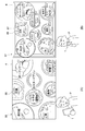
- FIG. 11 (A) and 11 (B) show the photographer when the photographer P uses the rear camera 3 of the display device 1 to photograph a plate on which a plurality of dishes are placed on the tray.
- the state of the above and examples of the display images 56 and 57 displayed on the display unit 4 of the display device 1 are shown.
- the display image 56 of FIG. 11A is an image displayed on the display unit 4 when the photographer P takes a picture with the display device 1 away from his / her eyes and close to the plate.
- the display image 57 of FIG. 11B is an image displayed on the display unit 4 when the photographer P takes a picture with the display device 1 close to the eyes and away from the plate. In the image taken by moving the display device 1 shown in FIG.
- the plurality of plates that are the subjects are enlarged as compared with the image taken by moving the display device 1 shown in FIG. 11 (B) away from the plate.
- the image looks like this.
- the display image is generated so that it appears to be continuously connected to the scenery outside the.
- the distance between the viewpoint of the photographer P and the display unit 4 can be obtained by the three-dimensional position calculation process of the viewpoint described in the first embodiment.
- the display image 56 is superposed on the character image 86 of the name of the food served on each dish. Will be generated.
- the calculated distance is less than the threshold value, as shown in FIG. 11B, in addition to the character image 86 of the food name, the character image 87 showing food information such as calorie information and allergy information is superimposed.
- the display image 57 is generated. Further, in the examples shown in FIGS.
- the display content is changed and the size of the character image is changed according to the distance between the viewpoint of the photographer P and the display unit.
- FIG. 11 (B) as compared with FIG. 11 (A), since the photographer P looks at the display unit 4 with his / her eyes close to the display device 1, even relatively small characters are photographed. Person P can read. Moreover, since it is displayed in small characters, more information can be displayed.
- FIG. 11A by reducing the content information of the food served on the plate and enlarging the characters, the photographer P can roughly eat the food even if he / she takes his / her eyes off the display device 1. It is possible to grasp the content information of.
- the image generation unit 7 may generate the display image by changing the display content information of the superimposed image according to the distance between the viewpoint of the photographer P and the display unit.
- the change in the display content of the superimposition image includes the case where the displayed information content is different and the size of the superimposition image (here, the size of characters) displayed even if the information content is the same. It may be different.
- a display image is displayed so that the display device 1 can be seen through and the other side can be seen, and further, by superimposing the character image, characters indicating the name and food information are displayed on the food visually visually recognized. Is visually recognized as being placed.
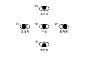
- the area indicated by the dot indicates the area of the pupil when the pupil is in the center of the eye.
- the line-of-sight detection process is performed by a line-of-sight detection processing unit (not shown).
- the line-of-sight detection processing unit detects the photographer's face from the image, and the positions of the left and right eyes of the face are detected by the image recognition processing. Further, the line-of-sight detection is performed based on the position of the pupil in the eye detected by the image recognition process.
- the pupils of the left and right eyes behave in the same way. For example, when the line of sight is directed upward without moving the face, the pupils of the left and right eyes move upward. Therefore, the line-of-sight detection can be performed based on the position of the pupil of one open eye.
- the line of sight is assumed to be in the center direction.
- the state 91 in which the pupil is on the left side of the eye is detected by image recognition, it is assumed that the line of sight is in the left direction.
- the state 92 in which the pupil is on the right side of the eye is detected by image recognition, it is assumed that the line of sight is in the right direction.
- the state 93 in which the pupil is on the upper side of the eye is detected by image recognition, it is assumed that the line of sight is upward.
- the state 94 in which the pupil is under the eye is detected by image recognition, it is assumed that the line of sight is downward.
- FIG. 13 is an example of a display image generated by changing the display content of the superimposing image according to the line-of-sight direction of the photographer.
- the line-of-sight direction is the central direction, as shown in FIG. 11B, a character image 86 indicating the name of food and a character image 87 indicating food information are superimposed corresponding to all the dishes. ..
- the photographer P considers that he / she is paying attention to the upper part of the displayed image, and as shown in FIG. 13, the grilled salmon, tofu, and pork saute located above the displayed image.
- the character image 86 of the name of the food and the character image 87 indicating the food information are superimposed to display more detailed information.
- the character image 86 indicating the name of the food is superimposed on the rice, pickles, and miso soup plates located below the display image 58 and the salad and custard pudding plates located in the center of the display image 58 in the vertical direction. And display simplified information. In this way, the display content of the superimposed image may be different depending on the line of sight of the photographer P.
- the display image is generated with the center of the left and right eyes as the viewpoint when the left and right eyes are open, and the center of the other open eye as the viewpoint when one eye is closed. I gave an example to do.
- this technique can also be applied to binocular stereoscopic vision in which different images are presented to the left and right eyes by the display unit 4.
- FIG. 1 it will be described with reference to FIG. 1
- FIG. 14 is a schematic view illustrating binocular stereoscopic vision.
- the third order of the left eye viewpoint EL of the left eye 9L and the right eye viewpoint ER of the right eye 9R is performed by the same method as the above embodiment.
- the original positions are calculated respectively.
- the center of the pupil of each eye is defined as the viewpoint E.
- the image generation unit 7 performs coordinate conversion processing and occlusion complementation processing in the same manner as in the above embodiment using the left-eye viewpoint EL and the right-eye viewpoint ER, and the left-eye display image and the right-eye display image are generated.
- NS the third order of the left eye viewpoint EL of the left eye 9L and the right eye viewpoint ER of the right eye 9R
- the parallax barrier is a slit array in which vertical slits are arranged in the horizontal direction, and can be manufactured by lithography or the like on the display unit 4.
- the plurality of display pixels constituting the display unit 4 are arranged such that the display pixels for displaying the left-eye display image and the display pixels for displaying the right-eye display image are alternately and repeatedly arranged in the horizontal direction.
- the photographer P can further experience a high sense of immersion and presence in the world of AR.
- the embodiment of the present technology is not limited to the above-described embodiment, and various changes can be made without departing from the gist of the present technology.
- the result of image recognition is used when recognizing the relative positional relationship, but in addition to this, from the IMU (inertial measurement unit) as the third sensor mounted on the display device 1.
- the acquired position / orientation information of the display device 1 may be used.
- the self-position / orientation information of the display device estimated by using SLAM Simultaneous Localization and Mapping
- the camera provided with both the image sensor and the distance sensor has been described as an example, but the image sensor and the distance sensor may be provided separately. In this case, the image sensor and the distance sensor are arranged close to each other.
- the coordinate conversion process in the display image generation method is performed in consideration of the positional relationship between the image sensor and the distance sensor. For example, for simplification of calculation, the image sensor of the rear camera is calibrated separately from the distance sensor of the rear camera, and the RGB value is mapped to the distance value to obtain the point cloud. Only the system can be calculated.
- a distance image obtained from the ToF type distance sensor of the front camera 6 is used, but the present invention is not limited to this.
- the distance image which is the sensing result obtained from the ToF type distance sensor, includes both the distance information and the two-dimensional position information of the photographer's eyes.
- To calculate the three-dimensional position of the viewpoint it is sufficient to have these distance information and the two-dimensional position information of the photographer's eyes. These pieces of information may be acquired by the same sensor, or may be acquired by different sensors.
- a distance sensor such as a structured light sensor or a patterned stereo sensor may be used as the second sensor for acquiring the distance information and the two-dimensional position information of the photographer's eyes.
- a stereo camera using two cameras (image sensors) may be used as the second sensor.
- a sensor that acquires two-dimensional position information of the eyes may be provided separately from the sensor that acquires the distance information, and the second sensor that acquires the distance information and the two-dimensional position information of the photographer's eyes is one or more sensors. It may be composed of.
- the ToF method has a smaller occlusion area than the structured light sensor, the patterned stereo sensor, and the stereo camera. Therefore, it is more preferable to use the ToF type distance sensor from the viewpoint of stably generating a display image without a sense of discomfort.
- a face detection and a two-dimensional position of the pupils of the left and right eyes are detected using the distance image acquired by the front camera 6.
- Face detection and two-dimensional position detection of the pupils of the left and right eyes may be performed using the RGB image acquired by the image sensor of the front camera 6.
- a virtual object or a character image is given as an example as an image for superimposition, but the present invention is not limited to these.
- an object region or the like cut out from an actually captured image may be used as the superimposing image, or an image processed such as changing the color of the cut out object region or the like may be used as the superimposing image.
- this technology can be applied even when displaying a virtual object fixed in a room with AR, and the photographer can enjoy a more realistic feeling of the size of the virtual object.
- the present technology can have the following configurations.
- a first image sensor arranged on the first surface side of the main body of the apparatus, The first distance sensor arranged on the first surface side and A second sensor arranged on the second surface side opposite to the first surface, The display unit arranged on the second surface side and The distance between the two-dimensional image of the subject acquired by the first image sensor and the first distance based on the three-dimensional position information of the photographer's viewpoint calculated based on the sensing result acquired by the second sensor.
- a display device including an image generation unit that generates a display image to be displayed on the display unit using the distance image of the subject acquired by the sensor.
- the image generation unit is a display device that generates the display image from the viewpoint of the photographer by performing coordinate conversion of the point cloud of the subject obtained by the two-dimensional image and the distance image.
- the image generation unit calculates the coordinates of the intersection of the straight line from the viewpoint to each point of the point cloud of the subject and the plane of the display unit with the three-dimensional position of the viewpoint of the photographer as the origin, and of the subject.
- a display device that generates the display image by converting the coordinates of the point cloud so that each point of the point cloud is mapped to the corresponding intersection coordinates.
- the image generation unit is a display device that generates the display image by complementing the occlusion area in the image viewed from the viewpoint of the photographer generated by coordinate conversion. (5) The display device according to any one of (2) to (4) above. A third sensor for acquiring the position / orientation information of the display device is further provided. The image generation unit is a display device that generates the display image using the position / orientation information. (6) The display device according to any one of (2) to (5) above. When the image generation unit calculates the three-dimensional position information of the viewpoint of the photographer from the sensing result of the second sensor, the image generation unit calculates the three-dimensional position information of the viewpoint according to the open / closed state of the eyes of the photographer. Display device. (7) The display device according to (6) above.
- the image generation unit uses the other eye that is open when one eye of the photographer is closed as the viewpoint, and the center of the line segment connecting both eyes when both eyes of the photographer are open.
- a display device that calculates the above three-dimensional position information as a viewpoint.
- the image generation unit is a display device that generates the display image using the right-eye image and the left-eye image generated with the positions of the left and right eyes of the photographer as viewpoints.
- the image generation unit is a display device that generates the display image on which the superimposing image is superimposed. (10) The display device according to (9) above.
- the image generation unit is a display device that generates the display image by superimposing a superposition image in which the display content is changed according to the distance between the photographer's viewpoint and the display unit.
- the image generation unit is a display device that generates the display image by superimposing the superimposition image whose display contents are changed according to the line of sight of the photographer.
- the display device according to any one of (1) to (11) above.
- a display device that includes distance information and two-dimensional position information of the photographer's eyes in the sensing result acquired by the second sensor.
- the second sensor is a display device that is a ToF (Time of Flight) sensor.
- a two-dimensional image of the subject is acquired from the first image sensor of the display device including the second sensor arranged in the above and the display unit arranged on the second surface side.
- the distance image of the subject is acquired from the first distance sensor, and the distance image is obtained.
Landscapes
- Engineering & Computer Science (AREA)
- Theoretical Computer Science (AREA)
- Physics & Mathematics (AREA)
- General Physics & Mathematics (AREA)
- General Engineering & Computer Science (AREA)
- Multimedia (AREA)
- Human Computer Interaction (AREA)
- Signal Processing (AREA)
- Computer Vision & Pattern Recognition (AREA)
- Computer Hardware Design (AREA)
- Software Systems (AREA)
- Artificial Intelligence (AREA)
- Health & Medical Sciences (AREA)
- Computer Graphics (AREA)
- Computing Systems (AREA)
- Databases & Information Systems (AREA)
- Evolutionary Computation (AREA)
- General Health & Medical Sciences (AREA)
- Medical Informatics (AREA)
- Studio Devices (AREA)
- Geometry (AREA)
- Electrophonic Musical Instruments (AREA)
Abstract
【課題】表示部に表示される画像と表示装置の外側の景色とがつながってみえるように画像表示することができる表示装置、画像生成方法及びプログラムを提供する。 【解決手段】表示装置は、第1の画像センサと、第1の距離センサと、第2のセンサと、表示部と、画像生成部と、を具備する。上記第1の画像センサは、装置本体の第1の面側に配置される。上記第1の距離センサは、上記第1の面側に配置される。上記第2のセンサは、上記第1の面と反対側の第2の面側に配置される。上記表示部は、上記第2の面側に配置される。上記画像生成部は、上記第2のセンサで取得されたセンシング結果に基づいて算出された撮影者の視点の三次元位置情報に基づき、上記第1の画像センサにより取得された被写体の二次元画像と上記第1の距離センサにより取得された上記被写体の距離画像を用いて、上記表示部に表示する表示画像を生成する。
Description
本技術は、表示装置、画像生成方法及びプログラムに関する。
スマートフォン等の携帯電話やタブレット端末といった、表示部を有するモバイルデバイスが広く浸透している。カメラを備えたモバイルデバイスではカメラにより撮影された画像を表示部に表示したり、当該画像に重ねて拡張現実(Augmented Reality;AR)情報を提示したりすることができる。例えば、モバイルデバイスに搭載されるカメラにより撮影されたモバイルデバイスの向こう側の景色を表示部に表示することによって、撮影者に没入感、臨場感の高いAR体験を提供することが行われている。
特許文献1には、デバイスの向こう側の風景がユーザの視点位置に伴って変化し表示される技術が開示されている。特許文献1には、遠隔コミュニケーションの臨場感を改善するための技術が記載されており、表示素子と撮像素子を埋め込んだ特殊な表示パネルを用いることで、様々な方向に異なる映像を表示することができ、同時に様々な方向から対象物を撮影することができることが記載されている。
表示装置に搭載されるカメラにより撮影された表示装置の向こう側の画像を表示部に表示する際、表示されている画像が、表示装置の中の箱庭のように視認される。
以上のような事情に鑑み、本技術の目的は、表示部に表示される画像と表示装置の外側の景色とがつながってみえるように画像表示することができる表示装置、画像生成方法及びプログラムを提供することにある。
上記目的を達成するため、本技術に係る表示装置は、第1の画像センサと、第1の距離センサと、第2のセンサと、表示部と、画像生成部と、を具備する。
上記第1の画像センサは、装置本体の第1の面側に配置される。
上記第1の距離センサは、上記第1の面側に配置される。
上記第2のセンサは、上記第1の面と反対側の第2の面側に配置される。
上記表示部は、上記第2の面側に配置される。
上記画像生成部は、上記第2のセンサで取得されたセンシング結果に基づいて算出された撮影者の視点の三次元位置情報に基づき、上記第1の画像センサにより取得された被写体の二次元画像と上記第1の距離センサにより取得された上記被写体の距離画像を用いて、上記表示部に表示する表示画像を生成する。
上記第1の画像センサは、装置本体の第1の面側に配置される。
上記第1の距離センサは、上記第1の面側に配置される。
上記第2のセンサは、上記第1の面と反対側の第2の面側に配置される。
上記表示部は、上記第2の面側に配置される。
上記画像生成部は、上記第2のセンサで取得されたセンシング結果に基づいて算出された撮影者の視点の三次元位置情報に基づき、上記第1の画像センサにより取得された被写体の二次元画像と上記第1の距離センサにより取得された上記被写体の距離画像を用いて、上記表示部に表示する表示画像を生成する。
本発明のこのような構成によれば、撮影者の視点からみた表示画像を生成することができ、表示部に表示される画像の景色と表示装置の外側の景色とがつながっているように撮影者により視認され得る。
上記目的を達成するため、本技術に係る画像生成方法は、
装置本体の第1の面側に配置された第1の画像センサと、上記第1の面側に配置された第1の距離センサと、上記第1の面と反対側の第2の面側に配置された第2のセンサと、上記第2の面側に配置された表示部と、を備える表示装置の、上記第1の画像センサから被写体の二次元画像を取得し、
上記第1の距離センサから上記被写体の距離画像を取得し、
上記第2のセンサのセンシング結果を取得し、
上記センシング結果に基づいて撮影者の視点の三次元位置情報を算出し、
上記三次元位置情報に基づいて、上記二次元画像と上記距離画像を用いて、上記表示部に表示する表示画像を生成する。
装置本体の第1の面側に配置された第1の画像センサと、上記第1の面側に配置された第1の距離センサと、上記第1の面と反対側の第2の面側に配置された第2のセンサと、上記第2の面側に配置された表示部と、を備える表示装置の、上記第1の画像センサから被写体の二次元画像を取得し、
上記第1の距離センサから上記被写体の距離画像を取得し、
上記第2のセンサのセンシング結果を取得し、
上記センシング結果に基づいて撮影者の視点の三次元位置情報を算出し、
上記三次元位置情報に基づいて、上記二次元画像と上記距離画像を用いて、上記表示部に表示する表示画像を生成する。
上記目的を達成するため、本技術に係るプログラムは、
装置本体の第1の面側に配置された第1の画像センサと、上記第1の面側に配置された第1の距離センサと、上記第1の面と反対側の第2の面側に配置された第2のセンサと、上記第2の面側に配置された表示部を備える表示装置の上記第1の画像センサから被写体の二次元画像を取得するステップと、
上記第1の距離センサから上記被写体の距離画像を取得するステップと、
上記第2のセンサのセンシング結果を取得するステップと、
上記センシング結果に基づいて撮影者の視点の三次元位置情報を算出するステップと、
上記三次元位置情報に基づいて、上記二次元画像と上記距離画像を用いて、上記表示部に表示する表示画像を生成するステップ
を表示装置に実行させる。
以下、図面を用いて本技術にかかわる表示装置について説明する。
<第1の実施形態>
[表示装置の構成]
本技術は、表示装置としての、表示部を有するスマートフォン等の携帯電話やタブレット等のモバイルデバイスに好適に使用され得る。以下の実施形態においては、スマートフォンの形態の表示装置を例に挙げて説明する。
<第1の実施形態>
[表示装置の構成]
本技術は、表示装置としての、表示部を有するスマートフォン等の携帯電話やタブレット等のモバイルデバイスに好適に使用され得る。以下の実施形態においては、スマートフォンの形態の表示装置を例に挙げて説明する。
図1は本技術の第1の実施形態に係る表示装置の外形形状を説明するための斜視図である。図1(A)は表示部が位置する正面側から表示装置を見た斜視図であり、図1(B)は背面側から見た斜視図である。
図1に示すように、表示装置1は、筐体10と、リアカメラ3と、第2のセンサとしてのフロントカメラ6と、表示部4と、を備える。表示装置1は、筐体10にリアカメラ3、フロントカメラ6、表示部4を構成する表示パネル、駆動回路、及び各種センサ等が保持されて構成される。
図1に示すように、表示装置1は、筐体10と、リアカメラ3と、第2のセンサとしてのフロントカメラ6と、表示部4と、を備える。表示装置1は、筐体10にリアカメラ3、フロントカメラ6、表示部4を構成する表示パネル、駆動回路、及び各種センサ等が保持されて構成される。
表示装置1の本体は、背面側の第1の面2と、当該第1の面2の反対側に位置する正面側の第2の面5と、を有する。第1の面2と第2の面5とは平行の位置関係にある。図における互いに直交するxyz座標方向は、略直方体の表示装置1の横、縦、高さに相当する。第1の面2と平行な面をxy平面として、高さ方向に相当する表示装置1の厚み方向をz軸とする。
第1の面2側にはリアカメラ3の撮像レンズ3aが配置してあり、リアカメラ3は、第1の面2と向き合った被写体を撮影する。
第2の面5側にはフロントカメラ6の撮像レンズ6aが配置してあり、フロントカメラ6は、第2の面5と向き合った被写体を撮影する。当該被写体は、通常、撮影者である。
第2の面5には、表示部4を構成する表示パネルが設けられている。表示部4は、例えば液晶ディスプレイ、有機ELディスプレイ(Organic Electro-Luminescence Display)等の画像表示手段により構成される。表示部4は、図示しない通信部を通して外部機器から送受信される画像、入力操作用のボタン、フロントカメラ6及びリアカメラ3により撮影された画像等を表示可能に構成される。画像には静止画及び動画が含まれる。
一般に、表示装置1を用いて撮影を行うユーザである撮影者は、表示部4に表示される画像を見たり、表示部4に表示される操作画面から入力操作等を行う。したがって、撮影者は、表示部4を視認するために表示装置1の第2の面5側に位置する。明細書中、表示装置1の向こう側という表現をする場合があるが、これは撮影者からみた方向を示し、表示装置1の第1の面2側に相当する。表示装置1の向こう側には、リアカメラ3による撮影の対象となる被写体が位置する。
図2は、表示装置1の機能構成を示すブロック図である。
図2に示すように、表示装置1は、リアカメラ3と、フロントカメラ6と、画像生成部7と、記憶部8と、表示部4と、を有する。
図2に示すように、表示装置1は、リアカメラ3と、フロントカメラ6と、画像生成部7と、記憶部8と、表示部4と、を有する。
本実施形態では、リアカメラ3及びフロントカメラ6は、いずれも、画像センサの機能と、距離センサの機能とを備える。
画像センサは、被写体のカラー二次元画像(以下、RGB二次元画像、RGB画像というときがある。)を撮像する。
距離センサは、被写体の距離画像を撮像する。距離センサには、ToF(Time of flight)方式を好適に用いることができ、本実施形態ではToF方式の距離センサを用いる例を挙げる。ToF方式の距離センサでは、近赤外光(NIR光)を用いて、距離センサと被写体との距離情報を有する距離画像が取得される。第2のセンサとしてのフロントカメラ6のToF方式の距離センサにより取得されるセンシング結果である距離画像には、距離情報の他、撮影者の目の二次元位置情報も含まれる。
本実施形態では、リアカメラ3及びフロントカメラ6が、それぞれ、1つの撮像デバイスであり、RGB画像と距離画像の双方を取得することができる例をあげる。以下、RGB画像及び距離画像をあわせて単に画像というときがある。
図2に示すように、リアカメラ3は、画像センサの一部を構成するRGB画像用撮像素子31と、距離センサの一部を構成する距離画像用撮像素子32と、撮像処理回路33と、オンチップレンズ(図示せず)と、カラーフィルタ(図示せず)と、発光部(図示せず)と、を有する。
同様に、フロントカメラ6は、画像センサの一部を構成するRGB画像用撮像素子61と、距離センサの一部を構成する距離画像用撮像素子62と、撮像処理回路63と、オンチップレンズ(図示せず)と、カラーフィルタ(図示せず)と、を有する。
リアカメラ3(フロントカメラ6)において、RGB画像用撮像素子31(61)及び距離画像用撮像素子32(62)と、オンチップレンズとの間にカラーフィルタを設けることで、R画素、G画素、B画素及びNIR画素を配置することができる。
同様に、フロントカメラ6は、画像センサの一部を構成するRGB画像用撮像素子61と、距離センサの一部を構成する距離画像用撮像素子62と、撮像処理回路63と、オンチップレンズ(図示せず)と、カラーフィルタ(図示せず)と、を有する。
リアカメラ3(フロントカメラ6)において、RGB画像用撮像素子31(61)及び距離画像用撮像素子32(62)と、オンチップレンズとの間にカラーフィルタを設けることで、R画素、G画素、B画素及びNIR画素を配置することができる。
ここで、R画素は、赤(R:Red)の波長成分を透過するカラーフィルタを透過した光から、赤成分の光に対応した電荷を得る画素である。G画素は、緑(G:Green)の波長成分を透過するカラーフィルタを透過した光から、緑(G)成分の光に対応した電荷を得る画素である。B画素は、青(B:Blue)の波長成分を透過するカラーフィルタを透過した光から、青(B)成分の光に対応した電荷を得る画素である。NIR画素は、近赤外光(NIR光)の波長成分を透過するフィルタを透過した光から、NIR光の波長帯に対応した電荷を得る画素である。
撮像処理回路33(63)は、RGB画像用撮像素子31(61)及び距離画像用撮像素子32(62)で得られる撮像信号を処理して、被写体に対応したRGB画像及び距離画像を生成する。
オンチップレンズは、画素毎に設けられ、外部からの光を集光して各画素のカラーフィルタに入射させる。
距離センサの一部を構成する発光部は、カメラと被写体との距離を測定するために用いられる。発光部はNIR光を発光する。距離画像用撮像素子32(62)は、発光部から発光されたNIR光が被写体で反射したときの戻り光を受光する。発光部は、例えば発光ダイオード(LED)等の発光部材とそれを発光させるためのドライバ回路を含んで構成される。
オンチップレンズは、画素毎に設けられ、外部からの光を集光して各画素のカラーフィルタに入射させる。
距離センサの一部を構成する発光部は、カメラと被写体との距離を測定するために用いられる。発光部はNIR光を発光する。距離画像用撮像素子32(62)は、発光部から発光されたNIR光が被写体で反射したときの戻り光を受光する。発光部は、例えば発光ダイオード(LED)等の発光部材とそれを発光させるためのドライバ回路を含んで構成される。
表示部4は、画像生成部7で生成された表示画像を表示する。表示部4は、リアカメラ3及びフロントカメラ6それぞれで撮影された画像を表示可能に構成されるが、以下の説明では、リアカメラ3で撮影された画像が表示部4に表示される例を挙げる。
画像生成部7は、画像情報取得部70と、視点位置算出部71と、座標変換部72と、補完部73と、を有する。
画像情報取得部70は、リアカメラ3から被写体のRGB画像及び距離画像を取得し、フロントカメラ6から撮影者のRGB画像及び距離画像を取得する。なお、後述するように、表示部4に表示される画像の景色と表示装置1の外側の景色とが連続してつながって、表示装置1の向こう側があたかも透けてみえるような表示画像を生成する場合、フロントカメラ6からは少なくとも距離画像が取得されればよい。
視点位置算出部71は、フロントカメラ6で撮影された距離画像に基づいて、撮影者の視点の三次元位置を算出する。
座標変換部72は、撮影者の視点の三次元位置情報に基づいて、リアカメラ3で取得される画像を座標変換して、撮影者の視点から見たRGB画像となる表示画像を生成する。
補完部73は、座標変化部72で生成された表示画像内に、オクルージョン領域がある場合、このオクルージョン領域を補完して、表示部4に表示される表示画像を生成する。
画像生成部7における表示画像生成方法については後述する。
図3は、撮影者Pが本実施形態に係る表示装置1を左手21に把持している様子を示す図である。図3において、表示装置1の表示部4には、表示装置1の向こう側を撮影した画像が表示されている。
本実施形態においては、リアカメラ3を基準として取得された画像を撮影者Pの視点からみた画像に変換して表示画像51が生成される。これにより、図3に示すように、表示装置1の外側の景色13と表示装置1の表示部4に表示される表示画像53の景色とが連続して繋がっているように見える。これにより、撮影者にとって表示装置1の存在によって遮られている領域は、表示装置1が透けて向こう側の景色が見えているように、撮影者Pには認識され、表示部4に表示される景色が箱庭的なものでなくなる。したがって、例えば、画像中に、拡張現実(Augmented Reality;AR)情報である仮想物体等の重畳用画像を重畳させてAR表示した場合、ユーザは、ARの世界への高い没入感及び臨場感を味わうことができる。仮想物体や仮想文字といった仮想画像の重畳については、他の実施形態として後述する。
本実施形態においては、リアカメラ3を基準として取得された画像を撮影者Pの視点からみた画像に変換して表示画像51が生成される。これにより、図3に示すように、表示装置1の外側の景色13と表示装置1の表示部4に表示される表示画像53の景色とが連続して繋がっているように見える。これにより、撮影者にとって表示装置1の存在によって遮られている領域は、表示装置1が透けて向こう側の景色が見えているように、撮影者Pには認識され、表示部4に表示される景色が箱庭的なものでなくなる。したがって、例えば、画像中に、拡張現実(Augmented Reality;AR)情報である仮想物体等の重畳用画像を重畳させてAR表示した場合、ユーザは、ARの世界への高い没入感及び臨場感を味わうことができる。仮想物体や仮想文字といった仮想画像の重畳については、他の実施形態として後述する。
記憶部8は、RAM等のメモリデバイス、及びハードディスクドライブ等の不揮発性の記録媒体を含み、表示装置1の表示部4に表示される表示画像を生成する処理を、表示装置に実行させるためのプログラムを記憶する。
記録部8に記憶されるプログラムは、リアカメラ3から被写体の二次元画像であるRGB画像と、被写体の距離画像とを取得するステップと、フロントカメラ6のセンシング結果となる距離画像を取得するステップと、フロントカメラ6の距離画像に基づいて撮影者Pの視点の三次元位置情報を算出するステップと、当該三次元位置情報に基づいて、リアカメラ3により取得されたRGB画像と距離画像を用いて、表示部4に表示する表示画像を生成するステップと、を表示装置に実行させるためのものである。
記録部8に記憶されるプログラムは、リアカメラ3から被写体の二次元画像であるRGB画像と、被写体の距離画像とを取得するステップと、フロントカメラ6のセンシング結果となる距離画像を取得するステップと、フロントカメラ6の距離画像に基づいて撮影者Pの視点の三次元位置情報を算出するステップと、当該三次元位置情報に基づいて、リアカメラ3により取得されたRGB画像と距離画像を用いて、表示部4に表示する表示画像を生成するステップと、を表示装置に実行させるためのものである。
[表示画像生成方法]
図4は、表示画像生成方法の概略を説明する図である。
図4(A)に示すように、リアカメラ3で取得される被写体となる対象物11の画像は、リアカメラ3の位置を基準とした画像である。
図4(B)に示すように、本実施形態の表示画像生成方法では、リアカメラ3で取得される対象物11の画像を、視点Eから見た画像となるように座標変換して表示画像を生成する。更に、座標変換して生成された表示画像にオクルージョン領域がある場合は、オクルージョン領域の補完処理が行われて、表示部4に表示される表示画像が生成される。以下、説明する。
図4は、表示画像生成方法の概略を説明する図である。
図4(A)に示すように、リアカメラ3で取得される被写体となる対象物11の画像は、リアカメラ3の位置を基準とした画像である。
図4(B)に示すように、本実施形態の表示画像生成方法では、リアカメラ3で取得される対象物11の画像を、視点Eから見た画像となるように座標変換して表示画像を生成する。更に、座標変換して生成された表示画像にオクルージョン領域がある場合は、オクルージョン領域の補完処理が行われて、表示部4に表示される表示画像が生成される。以下、説明する。
図5は表示画像生成方法のフロー図である。
図5に示すように、画像情報取得部70により、リアカメラ3から被写体のRGB画像及び距離画像と、フロントカメラ6から撮影者のRGB画像及び距離画像が取得される(ST1)。リアカメラ3はリア側にキャリブレーションされ、フロントカメラ6はフロント側にキャリブレーションされている。リアカメラ3により取得されたRGB画像及び距離画像から、リアカメラ3から被写体となる対象物11までのポイントクラウド情報を取得することができる。
次に、視点位置算出部71により、フロントカメラ6で撮影された距離画像に基づいて、撮影者の視点の三次元位置が算出される(ST2)。算出処理については後述する。
次に、座標変換部72により、撮影者の視点の三次元位置情報を用いて、リアカメラ3で取得された画像が、撮影者の視点から見た画像となるように座標変換される(ST3)。座標変換処理については後述する。
次に、補完部73により、座標変換部72で座標変換された表示画像内に、オクルージョン領域がある場合、このオクルージョン領域が補完されて、表示部4に表示される表示画像が生成される(ST4)。オクルージョン領域の補完処理については後述する。
(視点の三次元位置算出処理)
図6を用いて視点について説明する。
図6(A)に示すように、撮影者Pの両目が開いている場合、撮影者Pの右目9Rと左目9Lそれぞれの瞳(黒目)の中心点を結んでなる線分を二等分する中心点を視点Eとする。
図6(B)に示すように、撮影者Pの一方の片目が閉じ、他方の片目が開いている場合、開いている目の瞳の中心点を視点Eとする。図6(B)に示す例では、右目9Rが閉じられており、開いている左目9Lの瞳の中心点が視点Eとなる。図6(B)では、視点Eを白抜きの円で表している。視点Eは、リアカメラ3で取得された画像を用いて撮影者Pから見た表示画像を生成する際の基準に用いられる。
図6を用いて視点について説明する。
図6(A)に示すように、撮影者Pの両目が開いている場合、撮影者Pの右目9Rと左目9Lそれぞれの瞳(黒目)の中心点を結んでなる線分を二等分する中心点を視点Eとする。
図6(B)に示すように、撮影者Pの一方の片目が閉じ、他方の片目が開いている場合、開いている目の瞳の中心点を視点Eとする。図6(B)に示す例では、右目9Rが閉じられており、開いている左目9Lの瞳の中心点が視点Eとなる。図6(B)では、視点Eを白抜きの円で表している。視点Eは、リアカメラ3で取得された画像を用いて撮影者Pから見た表示画像を生成する際の基準に用いられる。
本実施形態では、フロントカメラ6は距離センサであるToFセンサを備えている。視点位置算出部71は、ToFセンサにより取得される距離画像であるNIR画像に対して、従来手法により顔検出と左右目の瞳の二次元位置の検出を行う。そして、その検出した画素のToF距離値から、左右目それぞれの瞳の中心点の3次元位置情報を取得する。
更に、視点位置算出部71は、取得した左右目それぞれの瞳の中心点の3次元位置情報から視点Eの三次元位置情報を算出する。上述の通り、撮影者Pの両目が開いている場合には左右の瞳の中心点を視点Eとし、片目が開いている場合には開いている目の瞳の中心を視点Eとする。
このように、本実施形態では、目の開閉状態に応じて最適な表示画像を生成することができる。
更に、視点位置算出部71は、取得した左右目それぞれの瞳の中心点の3次元位置情報から視点Eの三次元位置情報を算出する。上述の通り、撮影者Pの両目が開いている場合には左右の瞳の中心点を視点Eとし、片目が開いている場合には開いている目の瞳の中心を視点Eとする。
このように、本実施形態では、目の開閉状態に応じて最適な表示画像を生成することができる。
(座標変換処理)
図7を用いて、座標変換処理について説明する。
座標変換部72は、リアカメラ3で取得される被写体となる対象物11のポイントクラウドが、表示装置1の表示部4のどの座標値に写像されるかを算出する。
以下、図7及び後述する各式において示す記号E、D、A、F、R、Oは、それぞれの点の3次元位置を示す。
各記号の意味は次の通りである。
すなわち、
E:視点
A:表示部の左上の表示部原点
F:フロントカメラ
R:リアカメラ
O:対象物
視点Eは、上記視点の三次元位置算出方法により算出された視点の位置である。
表示部原点Aは、撮影者Pが、表示部4が配置される第2の面5に対向し、リアカメラ3及びフロントカメラ6が表示部4より上側に位置するように表示装置1を縦方向で把持したときの、矩形状の表示部4の表面の左上の角に位置する点である。
フロントカメラ6の点Fは、フロントカメラ6のカメラ座標の原点である。
リアカメラ3の点Rは、リアカメラ3のカメラ座標の原点である。
被写体である対象物11の点Oは、対象物11上の任意の点である。
また、3次元点間のベクトルの添え字は基準座標位置を表し、上記記号の大文字に対応する小文字で表す。xyzは座標軸方向を表す。
座標変換処理の計算は次に示す1、2の順序で行われる。
1.視点座標系eで、視点Eから対象物11の任意の点Oまでの直線と、表示部4の平面Dを、それぞれ、数式で表現する。視点座標系eとは、視点Eを原点としたときの座標系である。また、表示部4の平面Dは、表示部4の表面に相当する。
2.上記1の直線と平面との交点座標を求める。
尚、フロントカメラ6、リアカメラ3、表示部4は、それぞれの位置のキャリブレーションがされていて、平行の位置関係として取り扱うことができるものとする。
また、xyz座標方向において、z座標は、第2の面5から第1の面2に向かう方向に負の値を持つものとする。例えば、フロントカメラ6で検出される視点座標のz座標は常に負の値を持つ。撮影者Pが、表示部4が配置される第2の面5に対向し、リアカメラ3及びフロントカメラ6が表示部4より上側に位置するように表示装置1を縦方向で把持したときに、y座標は、撮影者Pからみて上から下に向かう方向に正の値を持つものとし、x座標は、撮影者Pからみて左から右に向かう方向に正の値を持つものとする。
図及び以下の説明において、Orはリアカメラ3の点Rを原点としたときの対象物11の点Oのxyz座標値を示す。Orx、Ory、Orzは、それぞれ、リアカメラ3の点Rを原点としたときの対象物11の点Oのx座標値、y座標値、z座標値を示す。
Oeは視点Eを原点としたときの対象物11の点Oのxyz座標値を示す。Oex、Oey、Oezは、それぞれ、視点Eを原点としたときの対象物11の点Oのx座標値、y座標値、z座標値を示す。
Dfはフロントカメラ6の点Fを原点としたときの平面D上の点のxyz座標値を示す。Dfx、Dfy、Dfzは、それぞれ、点Fを原点としたときの平面D上の点のx座標値、y座標値、z座標値を示す。
Efはフロントカメラ6の点Fを原点としたときの視点Eのxyz座標値を示す。Efx、Efy、Efzは、それぞれ、点Fを原点としたときの視点Eのx座標値、y座標値、z座標値を示す。
Afはフロントカメラ6の点Fを原点としたときの表示部原点Aのxyz座標値を示す。Afx、Afy、Afzは、それぞれ、点Fを原点としたときの表示部原点Aのx座標値、y座標値、z座標値を示す。
Frはリアカメラ3の点Rを原点としたときのフロントカメラ6の点Fのxyz座標値を示す。Frx、Fry、Frzは、それぞれ、リアカメラ3の点Rを原点としたときのフロントカメラ6の点Fのx座標値、y座標値、z座標値を示す。
まず、上記1について説明する。
視点座標系eにおける対象物の座標Oeの式は、
Oe=Or-Fr-Ef
となり、視点座標系eにおける点Eから点Oまでの直線は、次の3つの式によって現すことができる。この3つの式を式(1)とする。
x=a(Orx-Frx-Efx)
y=a(Ory-Fry-Efy) …式(1)
z=a(Orz-Frz-Efz)
ここで、aは媒介変数を表す。
視点座標系eにおける対象物の座標Oeの式は、
Oe=Or-Fr-Ef
となり、視点座標系eにおける点Eから点Oまでの直線は、次の3つの式によって現すことができる。この3つの式を式(1)とする。
x=a(Orx-Frx-Efx)
y=a(Ory-Fry-Efy) …式(1)
z=a(Orz-Frz-Efz)
ここで、aは媒介変数を表す。
視点座標系eにおける平面Dの式は、
De=-Ef+Af+Df
となり、次の3つの式によって表すことができる。この3つの式を(2)とする。
x=-Efx+Afx+Dfx
y=-Efy+Afy+Dfy …式(2)
z=-Efz+Afz
De=-Ef+Af+Df
となり、次の3つの式によって表すことができる。この3つの式を(2)とする。
x=-Efx+Afx+Dfx
y=-Efy+Afy+Dfy …式(2)
z=-Efz+Afz
次に、上記2について説明する。
(Dfx、Dfy)は表示部4上の座標(表示部座標という。)を示している。対象物11の任意の点Oが写像される表示部座標を求める、つまり、(Dfx、Dfy)を対象物11の任意の点Oを原点とする座標で表現する。これにより、リアカメラ3で得られる対象物11のポイントクラウドが、表示部4のどの表示部座標値に写像されるかが算出されることになる。具体的な算出方法は以下の通りである。
上記式(1)と式(2)より、
a(Orx-Frx-Efx)=-Efx+Afx+Dfx …式(3)
a(Ory-Fry-Efy)=-Efy+Afy+Dfy …式(4)
a(Orz-Frz-Efz)=-Efz+Afz …式(5)
上記式(5)より
a=(-Efz+Afz)/(Orz-Frz-Efz) …式(6)
上記式(3)、式(4)及び式(6)より
Dfx=(Orx-Frx-Efx)(-Efz+Afz)/(Orz-Frz-Efz)+Efx-Afx
Dfy=(Ory-Fry-Efy)(-Efz+Afz)/(Orz-Frz-Efz)+Efy-Afy
このように、(Dfx、Dfy)を対象物11の任意の点Oを原点とする座標で表現することができる。この座標変換処理により、リアカメラ3で得られる対象物11のポイントクラウドの各点が、それぞれ、表示部4のどの表示部座標値に写像されるかが算出される。これを、対象物11のポイントクラウドの全ての点で行うことによって、対象物11を表示部4のどこに表示すればよいかがわかる。これにより、表示部4に表示される表示装置1の向こう側の景色の画像は、撮影者Pの視点Eからみた画像となる。従って、撮影者Pに、表示部4に表示される画像の景色と表示装置1の外側の景色とが連続してつながっているように視認させ、表示装置1の向こう側があたかも透けてみえているような感じを与えることができる。
このように、座標変換処理では、撮影者Pの視点Eから対象物(被写体)のポイントクラウドの各点までの直線と、表示部4の平面との交点座標を点毎に算出し、被写体のポイントクラウドの各点が対応する交点座標に写像されるように表示画像が生成される。
(オクルージョン補完処理)
座標変換処理前の画像のポイントクラウドデータを用いて、上記座標変換処理を行って、座標変換処理前の画像とは異なる視点の画像を生成する場合、生成された画像にオクルージョン領域が発生する。オクルージョン補完処理では、このオクルージョン領域を補完する処理が実行されて、最終的に表示部4に表示される表示画像が生成される。
座標変換処理前の画像のポイントクラウドデータを用いて、上記座標変換処理を行って、座標変換処理前の画像とは異なる視点の画像を生成する場合、生成された画像にオクルージョン領域が発生する。オクルージョン補完処理では、このオクルージョン領域を補完する処理が実行されて、最終的に表示部4に表示される表示画像が生成される。
図8は、オクルージョン領域を説明するための図である。例えば、リアカメラ3を用いて被写体である人物12を正面より左斜めの方向から撮影し画像を取得したとする。このリアカメラ3で取得された画像のポイントクラウドデータを用いて、上記座標変換処理を行って人物を正面からみた画像が生成された場合、図8(A)に示すように、座標変換処理後の画像52に、変換処理前の画像において人物12が位置することによって隠れて見えなかった領域がオクルージョン領域81として発生する。このオクルージョン領域81は、ポイントクラウドデータが存在せず、画像の生成をすることができない領域である。図8(A)では、オクルージョン領域81を斜線で示している。
このオクルージョン領域81を補完することにより、図8(B)に示すように、欠落していたオクルージョン領域81の画像が補完された表示画像53が生成される。これにより、違和感のない表示画像を得ることができ、臨場感、没入感を高めることができる。
このオクルージョン領域81を補完することにより、図8(B)に示すように、欠落していたオクルージョン領域81の画像が補完された表示画像53が生成される。これにより、違和感のない表示画像を得ることができ、臨場感、没入感を高めることができる。
オクルージョン領域の補完処理には、例えば画像生成モデルGAN(Generative Adversarial Networks)等の画像補正処理を用いることができる。
また、時系列画像データが入力される場合は、時系列情報を利用するDVD-GAN(Dual Video Discriminator GAN)の手法を応用することができる。この手法では、従来の1フレーム単位のGANではなく、前後フレームの情報を活用できるため、より精度高くオクルージョン領域を補完することができ、より違和感のない表示画像を得ることができる。例えば、以前カメラに撮影されていた領域がオクルージョン領域となった場合に、過去に撮影された画像情報を活用することができる。
また、時系列画像データが入力される場合は、時系列情報を利用するDVD-GAN(Dual Video Discriminator GAN)の手法を応用することができる。この手法では、従来の1フレーム単位のGANではなく、前後フレームの情報を活用できるため、より精度高くオクルージョン領域を補完することができ、より違和感のない表示画像を得ることができる。例えば、以前カメラに撮影されていた領域がオクルージョン領域となった場合に、過去に撮影された画像情報を活用することができる。
以上のように、本実施形態では、フロントカメラ6の距離画像、リアカメラ3の距離画像及びRGB画像を利用して、リアカメラ3の画像センサにより取得されたリアカメラ3が視点となっている視野画像を、撮影者の視点が基準となった視野画像に変換して表示画像とすることができる。
尚、カメラ3及び6が表示部4よりも上側に位置するように表示装置1を縦向きに把持した場合を例にあげて表示画像生成方法の説明をしたが、表示装置1を横向きに把持した場合にも本技術を適用できる。カメラの向きにかかわらず、カメラ3及び6の座標系の相対的な向きや表示部原点Aの位置を変えることなく、前述の計算方法で表示画像を得ることができる。
<第2の実施形態>
本実施形態では、本技術の表示装置1によって向こう側を撮影した画像に、重畳用画像を重畳する例について説明する。ここでは重畳用画像が仮想物体である例について説明する。
図9及び10は、撮影者Pが左手21で表示装置1を把持している様子を示す。図9の表示装置1の表示部4には、表示装置1の向こう側を撮影した画像にクマの形態の仮想物体85が重畳表示された表示画像54が表示されている。図10の表示装置1の表示部4には、表示装置1の向こう側を撮影した画像に、仮想物体85が重畳表示された表示画像55が表示されている。図10において、撮影者Pは、仮想物体85が重畳された表示画像55を見て、表示画像55内の仮想物体85を空間内で、右手22で指し示している。
このように、上記の表示画像生成方法により生成された表示画像に、仮想物体85が重畳されて表示画像が生成されてもよい。
仮想物体85は、仮想空間における仮想的なオブジェクトである。本実施形態では、表示装置1のリアカメラ3によって撮影された実存する被写体の画像に仮想物体85が重畳された表示画像が表示部4に表示される。図9及び10に示すように、表示装置1の向こう側の景色13と連続して繋がっているようにみえる画像上に仮想物体85が重畳されて表示画像が生成されるので、撮影者Pは、仮想物体85が実在空間に存在するかのように感じることができ、ARの世界への高い没入感及び臨場感を味わうことができる。
また、図10に示すように、撮影者Pは、右手22で仮想物体85を指し示した際、表示画像55内の右手部分22aと表示装置1よりも外側に位置する右手部分22bとが連続して繋がっているように視認されるので、よりリアルに仮想物体85に触れているように感じることができる。
図10に示すように、仮想物体85を重畳表示した表示画像を見て撮影者の指による操作が行われることが想定される場合、次のように表示画像を生成してもよい。すなわち、上記の表示画像生成により生成された表示画像に映り込んだ手の領域を抽出し、リアカメラ3で得られる手の領域の距離情報と仮想物体85の位置に応じて、手の領域の一部が仮想物体85に接触する場合は、それに応じて仮想物体85が変形したり、移動したりするような表示画像を生成してもよい。
これにより、撮影者は、ARの世界へのより高い没入感及び臨場感を味わうことができる。
これにより、撮影者は、ARの世界へのより高い没入感及び臨場感を味わうことができる。
<第3の実施形態>
画像生成部7は、撮影者Pの視点と表示部との距離に応じて、表示画像に重畳する仮想画像の表示内容を変化させてもよい。以下、図11を用いて説明する。ここでは重畳用画像が文字画像である例について説明する。
画像生成部7は、撮影者Pの視点と表示部との距離に応じて、表示画像に重畳する仮想画像の表示内容を変化させてもよい。以下、図11を用いて説明する。ここでは重畳用画像が文字画像である例について説明する。
図11(A)及び(B)は、撮影者Pが表示装置1のリアカメラ3を用いてお盆の上に置かれている複数枚の料理がのった皿を撮影したときの、撮影者の様子及び表示装置1の表示部4に表示される表示画像56及び57の例を示す。
図11(A)の表示画像56は、撮影者Pが、表示装置1を目から離して皿に近づけて撮影したときの表示部4に表示される画像である。
図11(B)の表示画像57は、撮影者Pが、表示装置1を目に近づけ皿から離して撮影したときの表示部4に表示される画像である。
図11(A)に示す表示装置1を皿に近づけて撮影した画像では、図11(B)に示す表示装置1を皿から遠ざけて撮影した画像よりも、被写体である複数枚の皿が拡大したような画像となる。
本実施形態においても、上述の実施形態と同様に、撮影者Pの視点からみた画像が生成され、表示部4に表示される向こう側の景色と表示装置1の存在によって妨げられない表示装置1の外側の景色とが連続して繋がっているように見えるように、表示画像が生成される。
撮影者Pの視点と表示部4との距離は、第1の実施形態で説明した視点の三次元位置算出処理により求めることができる。本実施形態では、算出された距離が予め設定した閾値以上である場合、図11(A)に示すように、各皿に盛りつけられた食物の名前の文字画像86を重畳させて表示画像56が生成される。そして、算出された距離が閾値未満である場合、図11(B)に示すように、食物の名前の文字画像86に加えてカロリー情報やアレルギー情報といった食物情報を示す文字画像87を重畳させて表示画像57が生成される。
また、図11(A)及び(B)に示す例では、撮影者Pの視点と表示部との距離に応じて、表示内容を変化させる他、文字画像の大きさを変化させている。
図11(A)と比較して、図11(B)に示す例では、撮影者Pは表示装置1に目を近づけて表示部4を見ているため、比較的小さい文字であっても撮影者Pは読むことができる。また、小さい文字で表示するため、より多くの情報を表示することができる。一方、図11(A)においては、皿に盛りつけられた食物の内容情報をより少なくし、文字を大きくすることによって、撮影者Pは、表示装置1から目を離していても、おおまかな食物の内容情報を把握することができる。
また、図11(A)及び(B)に示す例では、撮影者Pの視点と表示部との距離に応じて、表示内容を変化させる他、文字画像の大きさを変化させている。
図11(A)と比較して、図11(B)に示す例では、撮影者Pは表示装置1に目を近づけて表示部4を見ているため、比較的小さい文字であっても撮影者Pは読むことができる。また、小さい文字で表示するため、より多くの情報を表示することができる。一方、図11(A)においては、皿に盛りつけられた食物の内容情報をより少なくし、文字を大きくすることによって、撮影者Pは、表示装置1から目を離していても、おおまかな食物の内容情報を把握することができる。
このように、画像生成部7は、撮影者Pの視点と表示部との距離に応じて、重畳用画像の表示内容情報を変化させて、表示画像を生成してもよい。なお、重畳用画像の表示内容の変化には、表示される情報内容が異なる場合の他、情報内容が同じであっても表示される重畳用画像の大きさ(ここでは文字の大きさ)が異なる場合も含まれる。
また、本実施形態では、表示装置1が透けて向こう側が見えるような表示画像が表示され、更に、文字画像が重畳されることにより、直視で視認した食物上にその名前や食物情報を示す文字が置かれているように視認される。
また、本実施形態では、表示装置1が透けて向こう側が見えるような表示画像が表示され、更に、文字画像が重畳されることにより、直視で視認した食物上にその名前や食物情報を示す文字が置かれているように視認される。
<第4の実施形態>
第3の実施形態においては、視点と表示部4との距離に応じて重畳用画像の表示内容を変化させる例をあげた。この他、ユーザの視線方向を推定し、推定した視線方向に応じて重畳用画像の表示内容を変化させてもよい。以下、図11(B)、図12及び13を用いて説明する。
第3の実施形態においては、視点と表示部4との距離に応じて重畳用画像の表示内容を変化させる例をあげた。この他、ユーザの視線方向を推定し、推定した視線方向に応じて重畳用画像の表示内容を変化させてもよい。以下、図11(B)、図12及び13を用いて説明する。
図12を用いて、フロントカメラ6で撮影して得た距離画像又はRGB画像から視線検出を行う処理の例について説明する。図12において、ドットで示す領域は目の中心に瞳があるときの瞳の領域を示す。視線検出処理は、図示しない視線検出処理部により行われる。
視線検出処理部により、画像から撮影者の顔が検出され、顔の左右の目の位置が画像認識処理で検出される。さらに、その画像認識処理で検出した目の中の瞳の位置に基づいて、視線検出が行なわれる。一般に、意識せず目を動かす場合、左右の目のそれぞれの瞳は同じ挙動を示す。例えば顔を動かさず、視線を上方向に向ける場合、左右の目のそれぞれの瞳は上方向に移動する。したがって、開いている1つの目の瞳の位置によって視線検出を行うことができる。
視線検出処理部により、画像から撮影者の顔が検出され、顔の左右の目の位置が画像認識処理で検出される。さらに、その画像認識処理で検出した目の中の瞳の位置に基づいて、視線検出が行なわれる。一般に、意識せず目を動かす場合、左右の目のそれぞれの瞳は同じ挙動を示す。例えば顔を動かさず、視線を上方向に向ける場合、左右の目のそれぞれの瞳は上方向に移動する。したがって、開いている1つの目の瞳の位置によって視線検出を行うことができる。
図12に示すように、目の中心に瞳がある状態90が画像認識で検出された場合、視線は中心方向であるとする。目の左側に瞳がある状態91が画像認識で検出された場合、視線が左方向であるとする。目の右側に瞳がある状態92が画像認識で検出された場合、視線が右方向であるとする。目の上側に瞳がある状態93が画像認識で検出された場合、視線が上方向であるとする。目の下側に瞳がある状態94が画像認識で検出された場合、視線が下方向であるとする。
図13は、撮影者の視線方向に応じて重畳用画像の表示内容を変化させて生成した表示画像例である。
例えば、視線方向が中心方向である場合、図11(B)に示すように、全ての各皿に対応して、食物の名前を示す文字画像86と食物情報を示す文字画像87が重畳される。
一方、視線方向が上方向である場合、撮影者Pは表示画像の上部分に注目しているとみなして、図13に示すように、表示画像の上方に位置する焼き鮭、豆腐、ポークソテーの皿に対応して、食物の名前の文字画像86と食物情報を示す文字画像87を重畳させ、より詳細な情報を表示する。一方、表示画像58の下方に位置するご飯、漬物、みそ汁の皿や表示画像58の上下方向における中央部に位置するサラダやカスタードプリンの皿には、食物の名前を示す文字画像86のみを重畳させ、簡素化した情報を表示する。このように、撮影者Pの視線に応じて、重畳画像の表示内容を異ならせてもよい。
<第5の実施形態>
上述の実施形態においては、左右の目が開いているときは、左右の目の中心を視点とし、片目が閉じているときは開いているもう一方の片目の中心を視点として、表示画像を生成する例をあげた。本技術は、本実施形態で説明するように、表示部4により左右の目に異なる画像を提示する両眼立体視に適用することもできる。以下、図14を用いて説明する。
上述の実施形態においては、左右の目が開いているときは、左右の目の中心を視点とし、片目が閉じているときは開いているもう一方の片目の中心を視点として、表示画像を生成する例をあげた。本技術は、本実施形態で説明するように、表示部4により左右の目に異なる画像を提示する両眼立体視に適用することもできる。以下、図14を用いて説明する。
図14は、両眼立体視を説明する模式図である。
本実施形態では、画像生成部7により、フロントカメラ6で得られた距離画像を用いて、上記実施形態と同様の手法で、左目9Lの左目用視点ELと右目9Rの右目用視点ERの三次元位置がそれぞれ算出される。各目の瞳の中心を視点Eとする。
更に、画像生成部7により、左目用視点EL及び右目用視点ERを用いて、上記実施形態と同様に座標変換処理、オクルージョン補完処理が行われ、左目用表示画像と右目用表示画像が生成される。
本実施形態では、画像生成部7により、フロントカメラ6で得られた距離画像を用いて、上記実施形態と同様の手法で、左目9Lの左目用視点ELと右目9Rの右目用視点ERの三次元位置がそれぞれ算出される。各目の瞳の中心を視点Eとする。
更に、画像生成部7により、左目用視点EL及び右目用視点ERを用いて、上記実施形態と同様に座標変換処理、オクルージョン補完処理が行われ、左目用表示画像と右目用表示画像が生成される。
立体表示を実現するには、表示部4にレンチキュラレンズを組み合わせたレンチキュラ方式やパララックスバリアを用いるパララックスバリア方式等がある。ここでは、パララックスバリア方式を例にあげて説明する。
パララックスバリアは、垂直スリットを水平方向に並べたスリットアレイであり、表示部4上にリソグラフィ等で作製可能である。表示部4から出る光線の水平進行方向をパララックスバリアのスリットで制限することで、光線の水平進行方向を制御することができる。表示部4を構成する複数の表示画素は、左目用表示画像を表示する表示画素、右目用表示画像を表示する表示画素が交互に水平方向に繰り返して配置される。
パララックスバリアは、垂直スリットを水平方向に並べたスリットアレイであり、表示部4上にリソグラフィ等で作製可能である。表示部4から出る光線の水平進行方向をパララックスバリアのスリットで制限することで、光線の水平進行方向を制御することができる。表示部4を構成する複数の表示画素は、左目用表示画像を表示する表示画素、右目用表示画像を表示する表示画素が交互に水平方向に繰り返して配置される。
このように、表示装置を立体表示可能な構成とすることにより、更に、撮影者Pは、ARの世界への高い没入感及び臨場感を味わうことができる。
<他の構成例>
本技術の実施の形態は、上述した実施の形態に限定されるものではなく、本技術の要旨を逸脱しない範囲において種々の変更が可能である。
例えば、座標変換処理時には対象物や視点の位置と表示装置の相対位置関係を認識する必要がある。上記実施形態では、相対位置関係を認識する際、画像認識の結果を用いる例をあげたが、これに加えて、表示装置1に搭載される第3のセンサとしてのIMU(inertial measurement unit)から取得される表示装置1の位置姿勢情報を用いてもよい。これにより、よりレスポンスの高い画像表示を実現することができる。また、SLAM(Simultaneous Localization and Mapping)を用いて推定した表示装置の自己位置姿勢情報を用いてもよい。
また、上述の実施形態では、画像センサと距離センサの双方を備えたカメラを例にあげて説明したが、画像センサと距離センサとを別々に設けてもよい。この場合、画像センサと距離センサとは近接して配置される。画像センサと距離センサとを別々に設ける場合、表示画像生成方法での座標変換処理は、画像センサと距離センサとの位置関係を考慮して行われる。例えば、計算の簡略化のため、リアカメラの画像センサはリアカメラの距離センサと別途キャリブレーションされていて、RGB値は距離値にマッピングされてポイントクラウドが得られているものとして、距離センサ座標系のみ計算対象とすることができる。
また、例えば、上述の実施形態において、視点の三次元位置を算出する際、フロントカメラ6のToF方式の距離センサから得られる距離画像を用いたが、これに限定されない。ToF方式の距離センサから得られるセンシング結果である距離画像には、距離情報と撮影者の目の二次元位置情報の双方が含まれている。視点の三次元位置の算出には、これら距離情報と撮影者の目の二次元位置情報があればよい。これらの情報は、同一のセンサで取得してもよいし、異なるセンサでそれぞれの情報を取得してもよい。
例えば、距離情報と撮影者の目の二次元位置情報の取得に、第2のセンサとして、ストラクチャードライトセンサやパターンドステレオセンサ等の距離センサを用いてもよい。或いは、第2のセンサとして2台のカメラ(画像センサ)を用いるステレオカメラを用いてもよい。距離情報を取得するセンサとは別に目の二次元位置情報を取得するセンサを設けてもよく、距離情報及び撮影者の目の二次元位置情報を取得する第2のセンサは、1以上のセンサから構成されてもよい。
尚、例えば、画像内の物体のテクスチャが少ない場合、ToF方式の方が、ストラクチャードライトセンサ、パターンドステレオセンサ及びステレオカメラよりもオクルージョン領域が少なくなる。このため、違和感のない表示画像を安定して生成する観点においてToF方式の距離センサを用いることがより好ましい。
また、例えば、上述の実施形態において、視点の三次元位置を算出する際、フロントカメラ6で取得される距離画像を用いて顔検出と左右目の瞳の二次元位置の検出を行う例をあげたが、これに限定されない。フロントカメラ6の画像センサで取得されるRGB画像を用いて顔検出と左右目の瞳の二次元位置の検出を行ってもよい。
また、上述の実施形態においては、重畳用画像として仮想物体や文字画像を例にあげたが、これらに限定されない。例えば、実際に撮影した画像から切り出した物体領域等を重畳用画像として用いてもよいし、切り出した物体領域等の色を変える等の加工を施したものを重畳用画像としてもよい。
また、ARで部屋に固定された仮想物体を表示する場合においても本技術を適用することができ、より現実的な仮想物体の大きさ感を撮影者は味わうことができる。
なお、本技術は以下のような構成もとることができる。
(1)
装置本体の第1の面側に配置された第1の画像センサと、
上記第1の面側に配置された第1の距離センサと、
上記第1の面と反対側の第2の面側に配置された第2のセンサと、
上記第2の面側に配置された表示部と、
上記第2のセンサで取得されたセンシング結果に基づいて算出された撮影者の視点の三次元位置情報に基づき、上記第1の画像センサにより取得された被写体の二次元画像と上記第1の距離センサにより取得された上記被写体の距離画像を用いて、上記表示部に表示する表示画像を生成する画像生成部
を具備する表示装置。
(2)
上記(1)に記載の表示装置であって、
上記画像生成部は、上記二次元画像及び上記距離画像により得られる上記被写体のポイントクラウドを座標変換して、上記撮影者の視点からみた上記表示画像を生成する
表示装置。
(3)
上記(2)に記載の表示装置であって、
上記画像生成部は、上記撮影者の視点の三次元位置を原点として、上記視点から上記被写体のポイントクラウドの各点までの直線と上記表示部の平面との交点座標を算出し、上記被写体のポイントクラウドの各点が対応する上記交点座標に写像されるように上記ポイントクラウドを座標変換して上記表示画像を生成する
表示装置。
(4)
上記(2)又は(3)に記載の表示装置であって、
上記画像生成部は、座標変換して生成された上記撮影者の視点からみた画像におけるオクルージョン領域を補完して、上記表示画像を生成する
表示装置。
(5)
上記(2)~(4)のいずれか1つに記載の表示装置であって、
上記表示装置の位置姿勢情報を取得する第3のセンサを更に具備し、
上記画像生成部は、上記位置姿勢情報を用いて上記表示画像を生成する
表示装置。
(6)
上記(2)~(5)のいずれか1つに記載の表示装置であって、
上記画像生成部は、上記第2のセンサのセンシング結果から上記撮影者の視点の三次元位置情報を算出する際、上記撮影者の目の開閉状態に応じて上記視点の三次元位置情報を算出する
表示装置。
(7)
上記(6)に記載の表示装置であって、
上記画像生成部は、上記撮影者の一方の目が閉じられている場合は開いている他方の目を視点とし、上記撮影者の両目が開いている場合は両目を結んだ線分の中心を視点として上記三次元位置情報を算出する
表示装置。
(8)
上記(2)~(7)のいずれか1つに記載の表示装置であって、
上記画像生成部は、上記撮影者の左右の目それぞれの位置を視点として生成した右目用画像と左目用画像を用いて上記表示画像を生成する
表示装置。
(9)
上記(2)~(8)のいずれか1つに記載の表示装置であって、
上記画像生成部は、重畳用画像を重畳した上記表示画像を生成する
表示装置。
(10)
上記(9)に記載の表示装置であって、
上記画像生成部は、上記撮影者の視点と上記表示部との距離に応じて表示内容を変化させた重畳用画像を重畳した上記表示画像を生成する
表示装置。
(11)
上記(9)に記載の表示装置であって、
上記画像生成部は、上記撮影者の視線に応じて表示内容を変化させた重畳用画像を重畳した上記表示画像を生成する
表示装置。
(12)
上記(1)~(11)のいずれか1つに記載の表示装置であって、
上記第2のセンサで取得されるセンシング結果には、距離情報及び上記撮影者の目の二次元位置情報が含まれる
表示装置。
(13)
上記(12)に記載の表示装置であって、
上記第2のセンサはToF(Time of Flight)センサである
表示装置。
(14)
装置本体の第1の面側に配置された第1の画像センサと、上記第1の面側に配置された第1の距離センサと、上記第1の面と反対側の第2の面側に配置された第2のセンサと、上記第2の面側に配置された表示部と、を備える表示装置の、上記第1の画像センサから被写体の二次元画像を取得し、
上記第1の距離センサから上記被写体の距離画像を取得し、
上記第2のセンサのセンシング結果を取得し、
上記センシング結果に基づいて撮影者の視点の三次元位置情報を算出し、
上記三次元位置情報に基づいて、上記二次元画像と上記距離画像を用いて、上記表示部に表示する表示画像を生成する
画像生成方法。
(15)
装置本体の第1の面側に配置された第1の画像センサと、上記第1の面側に配置された第1の距離センサと、上記第1の面と反対側の第2の面側に配置された第2のセンサと、上記第2の面側に配置された表示部を備える表示装置の上記第1の画像センサから被写体の二次元画像を取得するステップと、
上記第1の距離センサから上記被写体の距離画像を取得するステップと、
上記第2のセンサのセンシング結果を取得するステップと、
上記センシング結果に基づいて撮影者の視点の三次元位置情報を算出するステップと、
上記三次元位置情報に基づいて、上記二次元画像と上記距離画像を用いて、上記表示部に表示する表示画像を生成するステップ
を表示装置に実行させるプログラム。
1…表示装置
2…第1の面
3…リアカメラ(第1の画像センサ、第1の距離センサ)
4…表示部
5…第2の面
6…フロントカメラ(第2のセンサ)
7…画像生成部
E…視点
P…撮影者
9L…左目
9R…右目
11…対象物(被写体)
51、53、54~58…表示画像
81…オクルージョン領域
85…仮想物体(重畳用画像)
86、87…文字画像(重畳用画像)
2…第1の面
3…リアカメラ(第1の画像センサ、第1の距離センサ)
4…表示部
5…第2の面
6…フロントカメラ(第2のセンサ)
7…画像生成部
E…視点
P…撮影者
9L…左目
9R…右目
11…対象物(被写体)
51、53、54~58…表示画像
81…オクルージョン領域
85…仮想物体(重畳用画像)
86、87…文字画像(重畳用画像)
Claims (15)
- 装置本体の第1の面側に配置された第1の画像センサと、
前記第1の面側に配置された第1の距離センサと、
前記第1の面と反対側の第2の面側に配置された第2のセンサと、
前記第2の面側に配置された表示部と、
前記第2のセンサで取得されたセンシング結果に基づいて算出された撮影者の視点の三次元位置情報に基づき、前記第1の画像センサにより取得された被写体の二次元画像と前記第1の距離センサにより取得された前記被写体の距離画像を用いて、前記表示部に表示する表示画像を生成する画像生成部
を具備する表示装置。 - 請求項1に記載の表示装置であって、
前記画像生成部は、前記二次元画像及び前記距離画像により得られる前記被写体のポイントクラウドを座標変換して、前記撮影者の視点からみた前記表示画像を生成する
表示装置。 - 請求項2に記載の表示装置であって、
前記画像生成部は、前記撮影者の視点の三次元位置を原点として、前記視点から前記被写体のポイントクラウドの各点までの直線と前記表示部の平面との交点座標を算出し、前記被写体のポイントクラウドの各点が対応する前記交点座標に写像されるように前記ポイントクラウドを座標変換して前記表示画像を生成する
表示装置。 - 請求項2に記載の表示装置であって、
前記画像生成部は、座標変換して生成された前記撮影者の視点からみた画像におけるオクルージョン領域を補完して、前記表示画像を生成する
表示装置。 - 請求項2に記載の表示装置であって、
前記表示装置の位置姿勢情報を取得する第3のセンサを更に具備し、
前記画像生成部は、前記位置姿勢情報を用いて前記表示画像を生成する
表示装置。 - 請求項2に記載の表示装置であって、
前記画像生成部は、前記第2のセンサのセンシング結果から前記撮影者の視点の三次元位置情報を算出する際、前記撮影者の目の開閉状態に応じて前記視点の三次元位置情報を算出する
表示装置。 - 請求項6に記載の表示装置であって、
前記画像生成部は、前記撮影者の一方の目が閉じられている場合は開いている他方の目を視点とし、前記撮影者の両目が開いている場合は両目を結んだ線分の中心を視点として前記三次元位置情報を算出する
表示装置。 - 請求項2に記載の表示装置であって、
前記画像生成部は、前記撮影者の左右の目それぞれの位置を視点として生成した右目用画像と左目用画像を用いて前記表示画像を生成する
表示装置。 - 請求項2に記載の表示装置であって、
前記画像生成部は、重畳用画像を重畳した前記表示画像を生成する
表示装置。 - 請求項9に記載の表示装置であって、
前記画像生成部は、前記撮影者の視点と前記表示部との距離に応じて表示内容を変化させた重畳用画像を重畳した前記表示画像を生成する
表示装置。 - 請求項9に記載の表示装置であって、
前記画像生成部は、前記撮影者の視線に応じて表示内容を変化させた重畳用画像を重畳した前記表示画像を生成する
表示装置。 - 請求項1に記載の表示装置であって、
前記第2のセンサで取得されるセンシング結果には、距離情報及び前記撮影者の目の二次元位置情報が含まれる
表示装置。 - 請求項12に記載の表示装置であって、
前記第2のセンサはToF(Time of Flight)センサである
表示装置。 - 装置本体の第1の面側に配置された第1の画像センサと、前記第1の面側に配置された第1の距離センサと、前記第1の面と反対側の第2の面側に配置された第2のセンサと、前記第2の面側に配置された表示部と、を備える表示装置の、前記第1の画像センサから被写体の二次元画像を取得し、
前記第1の距離センサから前記被写体の距離画像を取得し、
前記第2のセンサのセンシング結果を取得し、
前記センシング結果に基づいて撮影者の視点の三次元位置情報を算出し、
前記三次元位置情報に基づいて、前記二次元画像と前記距離画像を用いて、前記表示部に表示する表示画像を生成する
画像生成方法。 - 装置本体の第1の面側に配置された第1の画像センサと、前記第1の面側に配置された第1の距離センサと、前記第1の面と反対側の第2の面側に配置された第2のセンサと、前記第2の面側に配置された表示部を備える表示装置の前記第1の画像センサから被写体の二次元画像を取得するステップと、
前記第1の距離センサから前記被写体の距離画像を取得するステップと、
前記第2のセンサのセンシング結果を取得するステップと、
前記センシング結果に基づいて撮影者の視点の三次元位置情報を算出するステップと、
前記三次元位置情報に基づいて、前記二次元画像と前記距離画像を用いて、前記表示部に表示する表示画像を生成するステップ
を表示装置に実行させるプログラム。
Priority Applications (3)
| Application Number | Priority Date | Filing Date | Title |
|---|---|---|---|
| US17/758,479 US20230028976A1 (en) | 2020-01-16 | 2021-01-06 | Display apparatus, image generation method, and program |
| KR1020227022433A KR20220127815A (ko) | 2020-01-16 | 2021-01-06 | 표시 장치, 화상 생성 방법 및 프로그램 |
| JP2021571151A JPWO2021145244A1 (ja) | 2020-01-16 | 2021-01-06 |
Applications Claiming Priority (2)
| Application Number | Priority Date | Filing Date | Title |
|---|---|---|---|
| JP2020004841 | 2020-01-16 | ||
| JP2020-004841 | 2020-01-16 |
Publications (1)
| Publication Number | Publication Date |
|---|---|
| WO2021145244A1 true WO2021145244A1 (ja) | 2021-07-22 |
Family
ID=76863999
Family Applications (1)
| Application Number | Title | Priority Date | Filing Date |
|---|---|---|---|
| PCT/JP2021/000159 WO2021145244A1 (ja) | 2020-01-16 | 2021-01-06 | 表示装置、画像生成方法及びプログラム |
Country Status (4)
| Country | Link |
|---|---|
| US (1) | US20230028976A1 (ja) |
| JP (1) | JPWO2021145244A1 (ja) |
| KR (1) | KR20220127815A (ja) |
| WO (1) | WO2021145244A1 (ja) |
Citations (10)
| Publication number | Priority date | Publication date | Assignee | Title |
|---|---|---|---|---|
| JP2005121838A (ja) * | 2003-10-15 | 2005-05-12 | Olympus Corp | カメラ |
| JP2006267026A (ja) * | 2005-03-25 | 2006-10-05 | Canon Inc | 画像処理方法、画像処理装置 |
| JP2013015896A (ja) * | 2011-06-30 | 2013-01-24 | Nippon Seiki Co Ltd | 部位検出装置及びプログラム |
| JP2013258583A (ja) * | 2012-06-13 | 2013-12-26 | Ntt Docomo Inc | 撮像画像表示装置、撮像画像表示方法、プログラム |
| JP2015531526A (ja) * | 2012-10-12 | 2015-11-02 | マイクロソフト テクノロジー ライセンシング,エルエルシー | タッチレス入力 |
| JP2016051918A (ja) * | 2014-08-28 | 2016-04-11 | 任天堂株式会社 | 情報処理端末、情報処理プログラム、情報処理端末システム、および情報処理方法 |
| JP2016201788A (ja) * | 2015-04-08 | 2016-12-01 | キヤノン株式会社 | 画像処理装置、撮像装置、画像処理方法、プログラム |
| JP2018022292A (ja) * | 2016-08-02 | 2018-02-08 | キヤノン株式会社 | 情報処理装置、情報処理装置の制御方法およびプログラム |
| JP2018025551A (ja) * | 2016-08-04 | 2018-02-15 | 株式会社Hielero | 点群データ変換システム及びその方法 |
| JP2019125345A (ja) * | 2018-01-12 | 2019-07-25 | キヤノン株式会社 | 情報処理装置、情報処理方法、プログラム、およびシステム |
Family Cites Families (2)
| Publication number | Priority date | Publication date | Assignee | Title |
|---|---|---|---|---|
| JP4576740B2 (ja) | 2001-04-02 | 2010-11-10 | ソニー株式会社 | 窓状撮像表示装置及びそれを使う双方向通信方法 |
| JP2019080223A (ja) * | 2017-10-26 | 2019-05-23 | 株式会社ソニー・インタラクティブエンタテインメント | カメラシステム |
-
2021
- 2021-01-06 KR KR1020227022433A patent/KR20220127815A/ko unknown
- 2021-01-06 WO PCT/JP2021/000159 patent/WO2021145244A1/ja active Application Filing
- 2021-01-06 JP JP2021571151A patent/JPWO2021145244A1/ja active Pending
- 2021-01-06 US US17/758,479 patent/US20230028976A1/en active Pending
Patent Citations (10)
| Publication number | Priority date | Publication date | Assignee | Title |
|---|---|---|---|---|
| JP2005121838A (ja) * | 2003-10-15 | 2005-05-12 | Olympus Corp | カメラ |
| JP2006267026A (ja) * | 2005-03-25 | 2006-10-05 | Canon Inc | 画像処理方法、画像処理装置 |
| JP2013015896A (ja) * | 2011-06-30 | 2013-01-24 | Nippon Seiki Co Ltd | 部位検出装置及びプログラム |
| JP2013258583A (ja) * | 2012-06-13 | 2013-12-26 | Ntt Docomo Inc | 撮像画像表示装置、撮像画像表示方法、プログラム |
| JP2015531526A (ja) * | 2012-10-12 | 2015-11-02 | マイクロソフト テクノロジー ライセンシング,エルエルシー | タッチレス入力 |
| JP2016051918A (ja) * | 2014-08-28 | 2016-04-11 | 任天堂株式会社 | 情報処理端末、情報処理プログラム、情報処理端末システム、および情報処理方法 |
| JP2016201788A (ja) * | 2015-04-08 | 2016-12-01 | キヤノン株式会社 | 画像処理装置、撮像装置、画像処理方法、プログラム |
| JP2018022292A (ja) * | 2016-08-02 | 2018-02-08 | キヤノン株式会社 | 情報処理装置、情報処理装置の制御方法およびプログラム |
| JP2018025551A (ja) * | 2016-08-04 | 2018-02-15 | 株式会社Hielero | 点群データ変換システム及びその方法 |
| JP2019125345A (ja) * | 2018-01-12 | 2019-07-25 | キヤノン株式会社 | 情報処理装置、情報処理方法、プログラム、およびシステム |
Also Published As
| Publication number | Publication date |
|---|---|
| JPWO2021145244A1 (ja) | 2021-07-22 |
| KR20220127815A (ko) | 2022-09-20 |
| US20230028976A1 (en) | 2023-01-26 |
Similar Documents
| Publication | Publication Date | Title |
|---|---|---|
| KR20210154814A (ko) | 패스 쓰루 이미징을 갖는 헤드 마운트 디스플레이 | |
| KR101822471B1 (ko) | 혼합현실을 이용한 가상현실 시스템 및 그 구현방법 | |
| CN107710108B (zh) | 内容浏览 | |
| TWI701941B (zh) | 圖像處理方法及裝置、電子設備及儲存介質 | |
| US10560683B2 (en) | System, method and software for producing three-dimensional images that appear to project forward of or vertically above a display medium using a virtual 3D model made from the simultaneous localization and depth-mapping of the physical features of real objects | |
| US20050219240A1 (en) | Horizontal perspective hands-on simulator | |
| US20060126926A1 (en) | Horizontal perspective representation | |
| JPWO2017094543A1 (ja) | 情報処理装置、情報処理システム、情報処理装置の制御方法、及び、パラメーターの設定方法 | |
| US20160148429A1 (en) | Depth and Chroma Information Based Coalescence of Real World and Virtual World Images | |
| CN108885342A (zh) | 用于低延迟渲染的宽基线立体 | |
| US11843758B2 (en) | Creation and user interactions with three-dimensional wallpaper on computing devices | |
| CN105611267B (zh) | 现实世界和虚拟世界图像基于深度和色度信息的合并 | |
| US11699259B2 (en) | Stylized image painting | |
| US20050248566A1 (en) | Horizontal perspective hands-on simulator | |
| CN108463839A (zh) | 信息处理装置和用户指南呈现方法 | |
| CN114371779A (zh) | 一种视线深度引导的视觉增强方法 | |
| US20230412779A1 (en) | Artistic effects for images and videos | |
| JP6775669B2 (ja) | 情報処理装置 | |
| WO2018074419A1 (ja) | 情報処理装置 | |
| JP7452434B2 (ja) | 情報処理装置、情報処理方法及びプログラム | |
| WO2021145244A1 (ja) | 表示装置、画像生成方法及びプログラム | |
| US20140362197A1 (en) | Image processing device, image processing method, and stereoscopic image display device | |
| JP6467039B2 (ja) | 情報処理装置 | |
| JP2011205385A (ja) | 立体映像制御装置および立体映像制御方法 | |
| WO2018187743A1 (en) | Producing three-dimensional images using a virtual 3d model |
Legal Events
| Date | Code | Title | Description |
|---|---|---|---|
| 121 | Ep: the epo has been informed by wipo that ep was designated in this application |
Ref document number: 21741897 Country of ref document: EP Kind code of ref document: A1 |
|
| ENP | Entry into the national phase |
Ref document number: 2021571151 Country of ref document: JP Kind code of ref document: A |
|
| NENP | Non-entry into the national phase |
Ref country code: DE |
|
| 122 | Ep: pct application non-entry in european phase |
Ref document number: 21741897 Country of ref document: EP Kind code of ref document: A1 |