WO2021144911A1 - プログラム生成装置、プログラム生成方法、及び生成プログラム - Google Patents
プログラム生成装置、プログラム生成方法、及び生成プログラム Download PDFInfo
- Publication number
- WO2021144911A1 WO2021144911A1 PCT/JP2020/001244 JP2020001244W WO2021144911A1 WO 2021144911 A1 WO2021144911 A1 WO 2021144911A1 JP 2020001244 W JP2020001244 W JP 2020001244W WO 2021144911 A1 WO2021144911 A1 WO 2021144911A1
- Authority
- WO
- WIPO (PCT)
- Prior art keywords
- component
- program
- attributes
- change
- operation program
- Prior art date
Links
Images


Classifications
-
- G—PHYSICS
- G05—CONTROLLING; REGULATING
- G05B—CONTROL OR REGULATING SYSTEMS IN GENERAL; FUNCTIONAL ELEMENTS OF SUCH SYSTEMS; MONITORING OR TESTING ARRANGEMENTS FOR SUCH SYSTEMS OR ELEMENTS
- G05B19/00—Programme-control systems
- G05B19/02—Programme-control systems electric
- G05B19/18—Numerical control [NC], i.e. automatically operating machines, in particular machine tools, e.g. in a manufacturing environment, so as to execute positioning, movement or co-ordinated operations by means of programme data in numerical form
- G05B19/4155—Numerical control [NC], i.e. automatically operating machines, in particular machine tools, e.g. in a manufacturing environment, so as to execute positioning, movement or co-ordinated operations by means of programme data in numerical form characterised by programme execution, i.e. part programme or machine function execution, e.g. selection of a programme
-
- B—PERFORMING OPERATIONS; TRANSPORTING
- B25—HAND TOOLS; PORTABLE POWER-DRIVEN TOOLS; MANIPULATORS
- B25J—MANIPULATORS; CHAMBERS PROVIDED WITH MANIPULATION DEVICES
- B25J9/00—Programme-controlled manipulators
- B25J9/16—Programme controls
- B25J9/1656—Programme controls characterised by programming, planning systems for manipulators
- B25J9/1669—Programme controls characterised by programming, planning systems for manipulators characterised by special application, e.g. multi-arm co-operation, assembly, grasping
-
- B—PERFORMING OPERATIONS; TRANSPORTING
- B25—HAND TOOLS; PORTABLE POWER-DRIVEN TOOLS; MANIPULATORS
- B25J—MANIPULATORS; CHAMBERS PROVIDED WITH MANIPULATION DEVICES
- B25J9/00—Programme-controlled manipulators
- B25J9/16—Programme controls
- B25J9/1656—Programme controls characterised by programming, planning systems for manipulators
-
- B—PERFORMING OPERATIONS; TRANSPORTING
- B25—HAND TOOLS; PORTABLE POWER-DRIVEN TOOLS; MANIPULATORS
- B25J—MANIPULATORS; CHAMBERS PROVIDED WITH MANIPULATION DEVICES
- B25J9/00—Programme-controlled manipulators
- B25J9/16—Programme controls
- B25J9/1679—Programme controls characterised by the tasks executed
- B25J9/1687—Assembly, peg and hole, palletising, straight line, weaving pattern movement
-
- G—PHYSICS
- G06—COMPUTING; CALCULATING OR COUNTING
- G06F—ELECTRIC DIGITAL DATA PROCESSING
- G06F8/00—Arrangements for software engineering
- G06F8/30—Creation or generation of source code
-
- G—PHYSICS
- G05—CONTROLLING; REGULATING
- G05B—CONTROL OR REGULATING SYSTEMS IN GENERAL; FUNCTIONAL ELEMENTS OF SUCH SYSTEMS; MONITORING OR TESTING ARRANGEMENTS FOR SUCH SYSTEMS OR ELEMENTS
- G05B19/00—Programme-control systems
- G05B19/02—Programme-control systems electric
- G05B19/418—Total factory control, i.e. centrally controlling a plurality of machines, e.g. direct or distributed numerical control [DNC], flexible manufacturing systems [FMS], integrated manufacturing systems [IMS], computer integrated manufacturing [CIM]
- G05B19/41805—Total factory control, i.e. centrally controlling a plurality of machines, e.g. direct or distributed numerical control [DNC], flexible manufacturing systems [FMS], integrated manufacturing systems [IMS], computer integrated manufacturing [CIM] characterised by assembly
-
- G—PHYSICS
- G05—CONTROLLING; REGULATING
- G05B—CONTROL OR REGULATING SYSTEMS IN GENERAL; FUNCTIONAL ELEMENTS OF SUCH SYSTEMS; MONITORING OR TESTING ARRANGEMENTS FOR SUCH SYSTEMS OR ELEMENTS
- G05B2219/00—Program-control systems
- G05B2219/30—Nc systems
- G05B2219/40—Robotics, robotics mapping to robotics vision
- G05B2219/40033—Assembly, microassembly
-
- G—PHYSICS
- G05—CONTROLLING; REGULATING
- G05B—CONTROL OR REGULATING SYSTEMS IN GENERAL; FUNCTIONAL ELEMENTS OF SUCH SYSTEMS; MONITORING OR TESTING ARRANGEMENTS FOR SUCH SYSTEMS OR ELEMENTS
- G05B2219/00—Program-control systems
- G05B2219/30—Nc systems
- G05B2219/40—Robotics, robotics mapping to robotics vision
- G05B2219/40269—Naturally compliant robot arm
-
- Y—GENERAL TAGGING OF NEW TECHNOLOGICAL DEVELOPMENTS; GENERAL TAGGING OF CROSS-SECTIONAL TECHNOLOGIES SPANNING OVER SEVERAL SECTIONS OF THE IPC; TECHNICAL SUBJECTS COVERED BY FORMER USPC CROSS-REFERENCE ART COLLECTIONS [XRACs] AND DIGESTS
- Y02—TECHNOLOGIES OR APPLICATIONS FOR MITIGATION OR ADAPTATION AGAINST CLIMATE CHANGE
- Y02P—CLIMATE CHANGE MITIGATION TECHNOLOGIES IN THE PRODUCTION OR PROCESSING OF GOODS
- Y02P90/00—Enabling technologies with a potential contribution to greenhouse gas [GHG] emissions mitigation
- Y02P90/02—Total factory control, e.g. smart factories, flexible manufacturing systems [FMS] or integrated manufacturing systems [IMS]
Definitions
- the present invention relates to a program generator, a program generation method, and a generation program.
- Patent Document 1 proposes a method for teaching a robot device a series of operations of assembly work. Specifically, in the method proposed in Patent Document 1, one assembly work included in the series of assembly work is started based on the sequence data of the series of assembly work when assembling the target product and the 3D data of each part. The assembly state of the target product at the time is reproduced, and the teaching points for the assembly work robot related to one assembly work are derived based on the reproduced assembly state. As a result, according to the method proposed in Patent Document 1, even if the order of a series of assembly operations is changed after the fact, it becomes easy to change the teaching points due to the change.
- the inventors of the present invention have found that the conventional method has the following problems. That is, at the site where the product assembly work is carried out, the target parts are out of stock, the production of the target parts is finished, the design is changed, multiple parts are used properly, the target parts are changed to standard products, and others.
- the assembly order is not changed, but some of the plurality of parts used may be changed due to reasons such as diverting the operation program to the product assembly work.
- the attributes such as shape and dimensions are different between the parts before the change and the parts after the change
- the operation for the parts before the change is applied to the parts after the change as it is. It is difficult to do, and the work content for the changed parts can be changed.
- the work content for the changed part can be changed according to the change of the state of the changed part in the product.
- the assembly order is not changed, but one part arranged in the middle is changed to another part having different dimensions. Is assumed. In this situation, the appropriate opening width of the gripper when gripping the modified part may be changed. Also, the proper placement of parts within the product that are placed on top of the changed parts can be changed.
- the contents of at least a part of the work included in the assembly work can be changed.
- the command to the robot device for appropriately performing the work is also changed.
- the driving amount of the gripper after the part change is changed in order to properly grip the changed part. Further, in order to appropriately arrange the target part on the changed part, the amount of movement of the gripper when transporting the target part is changed.
- the present invention has been made in view of such circumstances on one aspect, and an object of the present invention is to be used for assembly work after changing parts when at least a part of the parts constituting the product is changed. It is to provide a technique for reducing the trouble of generating a possible new operation program.
- the present invention adopts the following configuration in order to solve the above-mentioned problems.
- the program generation device includes a data acquisition unit that acquires an operation program for instructing a robot device of a series of operations of an assembly operation for assembling a product from a plurality of parts, and the plurality of parts.
- the change receiving unit that accepts the request for changing the part that changes at least one of the parts, and the attribute information indicating the attribute of each part, the attribute of the first part designated as the target of the part change, and the above.
- the attributes of the second component that replaces the first component due to the component change are compared, and the series of operations specified in the operation program is corrected due to the difference in the attributes of the first component and the second component.
- command correction unit that generates a new operation program for instructing the robot device of a series of operations of the assembly work after the parts are changed.
- the program generator identifies the difference in attributes between the first component and the second component from the attribute information, and operates affected by the component change so as to compensate for the difference in the specified attributes. Correct the command value of.
- a new operation program capable of appropriately assembling the product can be automatically generated even when the second component is used as the target component. Therefore, according to the configuration, when at least a part of the parts constituting the product is changed, it is possible to reduce the trouble of generating a new operation program that can be used for the assembly work after the parts change.
- the robot device may include a first tool used for work related to the first component included in the assembly work.
- the program generator refers to the specification information indicating the specifications of each of the plurality of tools including the first tool, and changes the component from the first component to the second component.
- a specification determination unit for determining whether or not the specifications of the tool can be followed may be further provided.
- the dimension of the second part exceeds the maximum opening width of the gripper, the weight of the second part exceeds the payload of the gripper, and the like.
- the specifications of the target tool used for the work related to the first part may not conform to the second part. If the specifications of the target tool do not conform to the second component, even if the command value of the operation is modified to compensate for the difference in attributes due to the component change, the target tool cannot perform the desired operation, and the product cannot be used. It may not be assembled properly. According to this configuration, it is possible to verify whether or not a malfunction occurs due to the specifications of the target tool (first tool) used for the target part to be changed, and thereby the reliability of the generated operation program. It is possible to improve the sex.
- the program generator When the specification determination unit determines that the specifications of the first tool cannot follow the component change, the program generator according to the one aspect refers to the specification information and is of the same type as the first tool.
- the second tool of the above which has a specification capable of following the change of the parts, may be further provided with a tool extraction unit for extracting the second tool from the plurality of tools. According to this configuration, when it is estimated that a malfunction occurs due to the specifications of the tool used for the part to be changed, an appropriate alternative tool (second tool) can be automatically extracted. As a result, it is possible to reduce the trouble of modifying the generated operation program.
- the command correction unit corrects the extracted command value of the operation in the operation program so as to further compensate for the change from the first tool to the second tool. By doing so, a new operation program for instructing the robot device of a series of operations of the assembly work after the component change may be generated. According to this configuration, it is possible to further reduce the time and effort for generating a new operation program that can be used for the assembly work after changing the parts by the amount that can automatically respond to the change of the tool.
- the attributes may include shape, dimensions, and position
- the modified command values may relate to the geometric movement of the robotic device.
- the attribute information may include a geometric model for each part, and the geometric model is a local coordinate system set for each part and having a reference point as an origin. The shape and dimensions may be expressed above.
- the program generator determines whether or not the reference point of the geometric model of the first component and the reference point of the geometric model of the second component are set by the same index.
- the index determination unit and the index determination unit may determine that the reference points of the first component and the second component are not set by the same index, before modifying the command value of the operation.
- a coordinate correction unit that modifies the reference point of the geometric model of the second component so as to be set by the same index as the reference point of the geometric model of the first component may be further provided.
- the reference point of the geometric model may be set by a different index between one part and another part because the geometric model is generated by different operators. If the reference point of the geometric model is set with a different index between the first part and the second part, and the target part is replaced with the second part as it is, the index of the reference point will be different. As a result, the position of the second component is deviated from the desired position and handled. Due to this, when the generated new operation program is executed, there is a possibility that the operation of the robot device may be defective. According to this configuration, when a new operation program is generated, it can be ensured that the reference points of the geometric models of the first component and the second component are set with the same index.
- the attribute may further include weight. According to this configuration, it is possible to automatically generate a new operation program corresponding to the change in the weight of the target component caused by the replacement of the first component with the second component. As a result, it is possible to reduce the trouble of generating a new operation program that can be used for the assembly work after changing the parts.
- the program generation device may further include a simulation unit that uses the generated new operation program to simulate a series of operations of the robot device in the assembly work after the component change. ..
- a simulation unit that uses the generated new operation program to simulate a series of operations of the robot device in the assembly work after the component change. ..
- extracting the operation to be modified means identifying the third component affected by the component change from the plurality of components, the first component or the specification.
- the operation related to the third component is specified from the series of operations, and the operation to be corrected due to the difference in the attributes of the first component and the second component is extracted from the specified operation. It may be composed of. According to this configuration, it is possible to appropriately extract the operation to be corrected by changing the part, thereby reducing the trouble of generating a new operation program that can be used for the assembly work after changing the part. can.
- one aspect of the present invention may be an information processing method or a program that realizes each of the above configurations, or such a program. It may be a storage medium that can be read by a computer or the like.
- the storage medium that can be read by a computer or the like is a medium that stores information such as a program by electrical, magnetic, optical, mechanical, or chemical action.
- the program generation method includes a step in which a computer acquires an operation program for instructing a robot device of a series of operations of an assembly operation for assembling a product from a plurality of parts, and the plurality of parts.
- the attribute of the first part designated as the target of the part change and the part are referred to by referring to the step of accepting the part change request for changing at least one of the parts and the attribute information indicating the attribute of each part.
- the attributes of the second component that replaces the first component due to the change are compared, and the series of operations specified in the operation program is corrected due to the difference in the attributes of the first component and the second component.
- the generation program includes a step of acquiring an operation program for instructing a computer of a series of operations of an assembly operation for assembling a product from a plurality of parts to a robot device, and the plurality of steps.
- the attribute of the first part designated as the target of the part change by referring to the step of accepting the part change request for changing at least one of the parts and the attribute information indicating the attribute of each part, and the above-mentioned
- the attributes of the second component that replaces the first component due to the component change are compared, and the series of operations specified in the operation program is corrected due to the difference in the attributes of the first component and the second component.
- the present invention when at least a part of the parts constituting the product is changed, it is possible to reduce the trouble of generating a new operation program that can be used for the assembly work after the parts change.
- FIG. 1 schematically illustrates an example of a situation in which the present invention is applied.
- FIG. 2A schematically illustrates an example of a process of assembling work before changing parts executed by the robot device according to the embodiment.
- FIG. 2B schematically illustrates an example of a process of assembling work before changing parts executed by the robot device according to the embodiment.
- FIG. 2C schematically illustrates an example of a process of assembling work before changing parts executed by the robot device according to the embodiment.
- FIG. 2D schematically illustrates an example of a process of assembling work before changing parts executed by the robot device according to the embodiment.
- FIG. 3A schematically illustrates an example of a process of assembling work after changing parts executed by the robot device according to the embodiment.
- FIG. 3A schematically illustrates an example of a process of assembling work after changing parts executed by the robot device according to the embodiment.
- FIG. 3B schematically illustrates an example of a process of assembling work after changing parts executed by the robot device according to the embodiment.
- FIG. 4 schematically illustrates an example of the hardware configuration of the controller according to the embodiment.
- FIG. 5 schematically illustrates an example of the robot device according to the embodiment.
- FIG. 6 schematically illustrates an example of the software configuration of the controller according to the embodiment.
- FIG. 7 schematically illustrates an example of the geometric model of each part according to the embodiment.
- FIG. 8A illustrates an example of a processing procedure related to creating an operation program of the controller according to the embodiment.
- FIG. 8B illustrates an example of a processing procedure related to creating an operation program of the controller according to the embodiment.
- FIG. 9 schematically illustrates an example of another situation to which the present invention is applied.
- the present embodiment an embodiment according to one aspect of the present invention (hereinafter, also referred to as “the present embodiment”) will be described with reference to the drawings.
- the embodiments described below are merely examples of the present invention in all respects. Needless to say, various improvements and modifications can be made without departing from the scope of the present invention. That is, in carrying out the present invention, a specific configuration according to the embodiment may be appropriately adopted.
- the data appearing in the present embodiment is described in natural language, more specifically, it is specified in a pseudo language, a command, a parameter, a machine language, etc. that can be recognized by a computer.
- FIG. 1 schematically illustrates an example of application situations of the present invention.
- the controller 1 according to the present embodiment is a computer configured to control the operation of the robot device 2 according to an operation program.
- the work performed by the robot device 2 includes an assembly work of assembling the product 3 from a plurality of parts.
- the controller 1 according to the present embodiment is configured to further generate a new operation program by receiving a request for component change and modifying a command value in the operation program according to the requested component change.
- NS The controller 1 according to the present embodiment is an example of the "program generator" of the present invention.
- the controller 1 acquires an operation program 50 for instructing the robot device 2 to perform a series of operations for assembling the product 3 from a plurality of parts. Further, the controller 1 accepts a component change request for changing at least one of the plurality of components. Next, the attribute information 121 indicating the attribute of each component is referred to, and the attribute of the first component designated as the target of the component change and the attribute of the second component replaced with the first component by the component change are compared. Based on the result of the comparison, the controller 1 extracts the operation to be corrected due to the difference in the attributes of the first component and the second component from the series of operations defined in the operation program 50.
- the controller 1 corrects the command value of the extracted operation in the operation program 50 so as to compensate for the difference in the attributes of the first component and the second component, thereby performing a series of assembly operations after the component change.
- a new operation program 55 for instructing the robot device 2 to operate is generated.
- the type of the robot device 2 may be appropriately selected according to the embodiment.
- the robot device 2 may be composed of one or a plurality of manipulators (industrial robots) such as a vertical articulated robot, a horizontal articulated robot, a SCARA robot, a parallel link robot, an orthogonal robot, and a cooperative robot.
- the robot device 2 may include one or more tools for performing work on the part.
- the one or more tools may include a first tool used for work relating to the first part included in the assembly work.
- the tool may be, for example, a gripper (robot hand), a suction device, a screw tightening device, a soldering device, or the like.
- the work on the parts may be, for example, gripping, transporting, inserting, placing, pressing, changing the posture, aligning, and the like.
- the operation program is composed of a series of command values for instructing each operation of the assembly work.
- Each command value may be appropriately configured to drive the robot device 2.
- Each command value is composed of, for example, a target value of a control amount or an operation amount of a component (for example, a tool, a joint, etc.) of the robot device 2 (for example, a target position, an opening width, a closing width, etc. of the gripper 25 described later). May be done.
- the product 3 is composed of a plurality of parts, the type thereof is not particularly limited and may be appropriately selected according to the embodiment.
- the product 3 may be, for example, a product assembled on a production line for electronic devices, electronic parts, automobile parts, and the like.
- the electronic component may be, for example, a substrate, a chip capacitor, a liquid crystal, a winding of a relay, or the like.
- the automobile parts may be, for example, connecting rods, shafts, engine blocks, power window switches, panels and the like.
- the product may be a final product produced after the completion of the manufacturing process, or an intermediate product produced in the middle of the manufacturing process. Each part may be appropriately selected according to the product.
- Each component may be, for example, a substrate, various chips, capacitors, connectors, pegs, sockets, holes, gears, bolts, screws, nuts, and the like.
- the attributes of a part are features that can be involved in the assembly work.
- the attributes of the parts are, for example, shape, dimensions, position, weight and the like.
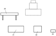
- the product 3 is composed of three parts 31 to 33, and the robot device 2 is a vertical articulated robot.
- the robot device 2 includes a gripper 25 as an end effector for carrying out the work of transporting the parts 31 to 33.
- the assembly work of the product 3 is to stack the parts 31 to 33 in order.
- the product 3 receives a request to change the component 31 to the component 35.
- the component 31 is an example of the first component
- the component 35 is an example of the second component.
- the gripper 25 is an example of the first tool. It should be noted that these limitations shown in FIG. 1 are merely specific examples for convenience of explanation.
- the configuration of the robot device 2, the configuration of the product 3, and the process of the assembly work may be appropriately determined according to the embodiment.
- the number of parts constituting the product 3 may be appropriately selected according to the embodiment.
- the parts to be changed may be appropriately selected from a plurality of parts constituting the product 3.
- FIGS. 2A to 2D schematically illustrate an example of an assembly work process for assembling the product 3 before changing the parts.
- the parts 31 to 33 are arranged at different supply positions.
- An example of this assembly work is composed of three steps.
- the first step is to place the part 31 at the target position in the target posture.
- the controller 1 moves the gripper 25 to the supply position of the component 31 with respect to the robot device 2.
- the controller 1 causes the robot device 2 to grip the component 31 by opening and closing the gripper 25.
- the controller 1 causes the robot device 2 to carry the gripped component 31 to the target position.
- the controller 1 causes the robot device 2 to open the gripper 25 and arrange the component 31 at the target position in the target posture.
- the first step is completed.
- the second step is to arrange the component 32 in the target posture at the target position on the component 31.
- the controller 1 moves the gripper 25 to the supply position of the component 32 with respect to the robot device 2.
- the controller 1 causes the robot device 2 to grip the component 32 by opening and closing the gripper 25.
- the controller 1 causes the robot device 2 to carry the gripped component 32 to the target position on the component 31.
- the controller 1 causes the robot device 2 to open the gripper 25 and arrange the component 32 at the target position on the component 31 in the target posture.
- the second step is completed.
- the third step is to arrange the component 33 in the target posture at the target position on the component 32.
- the controller 1 moves the gripper 25 to the supply position of the component 33 with respect to the robot device 2.
- the controller 1 causes the robot device 2 to grip the component 33 by opening and closing the gripper 25.
- the controller 1 causes the robot device 2 to carry the gripped component 33 to the target position on the component 32.
- the controller 1 causes the robot device 2 to open the gripper 25 and arrange the component 33 at the target position on the component 32 in the target posture.
- the third step is completed, and the assembly work of the product 3 is completed.
- a series of command values for realizing the operation of the robot device 2 in each of the above steps, such as the target position, opening width, and closing width of the gripper 25, is defined.
- An example of this operation program 50 may be appropriately generated by a method such as direct teaching, manual preparation (for example, use of a teaching pendant, programming, etc.), automatic planning (for example, motion planning, etc.).
- FIG. 3A schematically illustrates an example of the initial state of the assembly work for assembling the product 3 after changing the parts.
- FIG. 3B schematically illustrates an example of the completed state (that is, the completed state of the assembly work) of the product 3 after the parts are changed.
- the modified component 35 has different dimensions from the unmodified component 31.
- component 35 has dimensions that are wider than component 31 and lower than component 31.
- the supply position of the component 35 may be the same as or different from the supply position of the component 31.
- the controller 1 causes the robot device 2 to execute the operations of the first to third steps, that is, conveys the component 35, the component 32, and the component 33 to the target positions in order.
- the assembly work of the product 3 can be completed.
- the controller 1 uses the above-mentioned series of information processing to modify the command value in the operation program 50 according to the component change, thereby providing a new operation program 55 capable of executing the assembly work of the product 3 after the component change. Generate.
- the controller 1 After acquiring the operation program 50 and accepting the request for changing the parts, the controller 1 refers to the attribute information 121 and compares the attributes of the parts 31 and 35. As a result of this comparison, the controller 1 recognizes the dimensional difference between the component 31 and the component 35. Based on this recognition, the controller 1 extracts the operation to be corrected from the series of operations defined in the operation program 50.
- the operation to be modified is related to the first part that is changed to the second part.
- parts that have a dependency relationship with the first part such as the arrangement being determined by the first part, are also affected by the part change.
- the operation to be modified includes not only the work related to the first component but also the work related to the component having a dependency relationship with the first component. Therefore, to extract the operation subject to the above modification is to identify the third part affected by the part change from the plurality of parts, and to identify one or more operations related to the first part or the specified third part.
- each of the above parts (32, 33) is an example of a third part. As a result, it is possible to appropriately extract the operation to be corrected by changing the parts.
- one example of the operation extracted as the target of correction is the operation of gripping the component 31 by the gripper 25 and the operation of transporting the component 31 to the target position by the gripper 25. It is an operation.
- an operation of moving the gripper 25 to the supply position of the component 31 is also included as an example of the operation extracted as the target of correction.
- one example of the operation extracted as the target of correction is the operation of transporting each part (32, 33) to the target position by the gripper 25.
- the controller 1 modifies the command value of the extracted operation in the operation program 50 so as to compensate for the dimensional difference between the component 31 and the component 35.
- the opening width and the closing width of the gripper 25 defined for gripping the component 31 may be modified to large values so that the component 35 can be gripped.
- the target position of the gripper 25 defined for transporting the component 31 to the target position may be corrected to a lower value according to the height of the component 35 being lower than that of the component 31.
- the opening width of the gripper 25 defined for opening the component 31 at the target position may be corrected to a large value so that the component 35 can be opened.
- the target position of the gripper 25 defined for moving to the supply position of the component 31 may be modified to match the supply position of the component 35. Further, the target position of the gripper 25 defined for transporting each component (32, 33) to the target position may be corrected to a lower value according to the height of the component 35 being lower than that of the component 31. ..
- Each modification amount may be determined according to the difference in attributes between the first component and the second component. Modification rules may be set as appropriate. For example, the difference in the attribute value between the first component and the second component may be applied to each modification amount as it is. In the above specific example, the dimensional difference between the component 31 and the component 35 may be applied to each correction amount as it is. Further, for example, each correction amount may be derived according to a predetermined rule from the difference in the attribute values between the first component and the second component. As a result, a new operation program 55 can be generated.
- the controller 1 can automatically generate a new operation program 55 by modifying the command value in the operation program 50 in response to the request for changing the parts.
- the command value of the operation affected by the component change has been corrected by the above processing so as to be suitable for the attribute of the changed second component (part 35 in the above specific example). Is. Therefore, according to the generated new operation program 55, it is possible to appropriately carry out the assembly work of the product 3 after changing the parts from the first part to the second part. Therefore, according to the present embodiment, when at least a part of the parts constituting the product 3 is changed, it is possible to reduce the trouble of generating a new operation program 55 that can be used for the assembly work after the parts change. Can be done.
- a new operation program 55 that can be used for the assembly work after the component change can be automatically generated according to the designation of the component change. Therefore, by using the controller 1 according to the present embodiment, even a relatively beginner can generate a new operation program according to the component change.
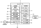
- FIG. 4 schematically illustrates an example of the hardware configuration of the controller 1 according to the present embodiment.
- the controller 1 according to the present embodiment is a computer to which the control unit 11, the storage unit 12, the external interface 13, the input device 14, the output device 15, and the drive 16 are electrically connected.
- the external interface is described as "external I / F".
- the control unit 11 includes a CPU (Central Processing Unit), a RAM (Random Access Memory), a ROM (Read Only Memory), and the like, which are hardware processors, and is configured to execute information processing based on a program and various data.
- NS The storage unit 12 is an example of a memory, and is composed of, for example, a hard disk drive, a solid state drive, or the like. In the present embodiment, the storage unit 12 stores various information such as the operation program 50, the generation program 81, the attribute information 121, the specification information 123, and the robot information 125.
- the operation program 50 is composed of a series of command values for instructing the robot device 2 to perform a series of operations for assembling the product 3 from a plurality of parts.
- the generation program 81 is a program for causing the controller 1 to execute information processing (FIGS. 8A and 8B), which will be described later, to generate a new operation program 55 in response to a request for changing parts.
- the generation program 81 includes a series of instructions for the information processing.
- the attribute information 121 includes information on the attributes of each component that can be used in the product 3.
- the parts that can be used in the product 3 include the above-mentioned parts (31 to 33, 35). Attribute information 121 may include information about the shape, dimensions, and position (ie, geometric attributes) of each part.
- the position of each component is, for example, the above-mentioned supply position or the like.
- Geometric attributes may further include the orientation of each component (eg, roll, pitch, yaw).
- Attribute information 121 may further include information about weight (ie, other attributes than geometric attributes).
- the specification information 123 includes information regarding the specifications of each tool that can be attached to the robot device 2.
- the specifications of the tool relate to the ability to perform tasks such as the maximum opening width of the gripper.
- the specifications indicated by the specification information 123 may be appropriately selected depending on the type of tool.
- the tools that can be attached to the robot device 2 include the gripper 25.
- the robot information 125 includes information regarding the specifications of the robot device 2. Details will be described later.
- the external interface 13 is, for example, a USB (Universal Serial Bus) port, a dedicated port, or the like, and is an interface for connecting to an external device.
- the type and number of the external interfaces 13 may be appropriately selected according to the type and number of connected external devices.
- the controller 1 is connected to the robot device 2 via the external interface 13. As a result, the controller 1 is configured to be able to control the operation of the robot device 2.
- the configuration for controlling the operation of the robot device 2 does not have to be limited to such an example, and may be appropriately determined according to the embodiment.
- the controller 1 and the robot device 2 include a communication interface
- the controller 1 may be connected to the robot device 2 via the communication interface.
- another information processing device for example, another controller
- the controller 1 may be connected to the robot device 2 via the other information processing device.
- the input device 14 is, for example, a device for inputting a mouse, a keyboard, or the like.
- the output device 15 is, for example, a device for outputting a display, a speaker, or the like. The operator can operate the controller 1 by using the input device 14 and the output device 15.
- the drive 16 is, for example, a CD drive, a DVD drive, or the like, and is a drive device for reading various information such as a program stored in the storage medium 91.
- the storage medium 91 electrically, magnetically, optically, mechanically or chemically acts on the information of the program or the like so that the computer or other device, the machine or the like can read various information of the stored program or the like. It is a medium that accumulates by.
- At least one of the operation program 50, the generation program 81, the attribute information 121, the specification information 123, and the robot information 125 may be stored in the storage medium 91.
- the controller 1 may acquire at least one of the operation program 50, the generation program 81, the attribute information 121, the specification information 123, and the robot information 125 from the storage medium 91.
- FIG. 4 illustrates a disc-type storage medium such as a CD or DVD as an example of the storage medium 91.
- the type of the storage medium 91 is not limited to the disc type, and may be other than the disc type. Examples of storage media other than the disk type include semiconductor memories such as flash memories.
- the type of the drive 16 may be arbitrarily selected according to the type of the storage medium 91.
- the control unit 11 may include a plurality of hardware processors.
- the hardware processor may be composed of a microprocessor, an FPGA (field-programmable gate array), a DSP (digital signal processor), or the like.
- the storage unit 12 may be composed of a RAM and a ROM included in the control unit 11. At least one of the external interface 13, the input device 14, the output device 15, and the drive 16 may be omitted.
- the controller 1 may include a communication interface for performing data communication with another information processing device.
- the controller 1 may be composed of a plurality of computers. In this case, the hardware configurations of the computers may or may not match.
- controller 1 may be a general-purpose PC (Personal Computer) (for example, a desktop PC, a tablet PC, etc.), a PLC (programmable logic controller), or the like, in addition to an information processing device designed exclusively for the provided service. good.
- PC Personal Computer
- PLC programmable logic controller
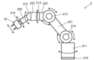
- FIG. 5 schematically illustrates an example of the hardware configuration of the robot device 2 according to the present embodiment.
- the robot device 2 is a 6-axis vertical articulated industrial robot, and includes a pedestal portion 210 and six joint portions 211 to 216.
- Each of the joints 211 to 216 has a built-in servomotor (not shown) so that the joints 211 to 216 can rotate around each axis.
- the first joint portion 211 is connected to the pedestal portion 210, and the portion on the tip end side is rotated around the axis of the pedestal.
- the second joint portion 212 is connected to the first joint portion 211, and the portion on the distal end side is rotated in the front-rear direction.
- the third joint portion 213 is connected to the second joint portion 212 via the link 221 and rotates the tip end side portion in the vertical direction.
- the fourth joint portion 214 is connected to the third joint portion 213 via the link 222, and the tip end side portion is rotated around the axis of the link 222.
- the fifth joint portion 215 is connected to the fourth joint portion 214 via the link 223, and the portion on the tip end side is rotated in the vertical direction.
- the sixth joint portion 216 is connected to the fifth joint portion 215 via the link 224, and the tip end side portion is rotated around the axis of the link 224.
- a gripper 25 is attached as an end effector to the tip end side of the sixth joint portion 216.
- Encoders are further built in each joint portion 211 to 216.
- the encoder is configured to measure the angle of each joint portion 211 to 216.
- the type of encoder is not particularly limited and may be appropriately selected depending on the embodiment.
- the measured values of the encoder are used to control the angles of the joints 211 to 216.
- the method of controlling the angles of the joint portions 211 to 216 may not be particularly limited, and may be appropriately selected depending on the embodiment.
- known methods such as PID (Proportional-Integral-Differential) control and PI control may be adopted.
- the conversion between the angles of the joints 211-216 and the position of the gripper 25 may be based on forward kinematics and inverse kinematics.
- the command value when moving the gripper 25 may be defined by the target position of the gripper 25.
- the target position of the gripper 25 may be converted into a target angle of each joint portion 211 to 216 by inverse kinematics.
- the driving amount of each joint portion 211 to 216 may be determined based on the difference between the target angle of each joint portion 211 to 216 and the current angle measured by the encoder.
- the hardware configuration of the robot device 2 does not have to be limited to such an example.
- the components can be omitted, replaced, and added as appropriate according to the embodiment.
- the robot device 2 may include a sensor other than an encoder in order to observe a controlled variable or other attributes.
- the robot device 2 may further include at least one of a visual sensor (eg, a camera) and a tactile sensor.
- the sensing data obtained by the sensor may be used for feedback control of the robot device 2.
- the operation of the robot device 2 may be controlled based on the sensing data obtained by the tactile sensor so that an excessive force does not act on the gripper 25.
- the operation of the robot device 2 may be controlled so as to move the gripper 25 to a desired position (for example, a position where each component can be gripped) based on the sensing data obtained by the visual sensor.
- a desired position for example, a position where each component can be gripped
- the number of axes of the robot device 2 does not have to be limited to 6 axes, and may be appropriately selected according to the embodiment.
- a known industrial robot may be used for the robot device 2.
- FIG. 6 schematically illustrates an example of a software configuration related to information processing of program generation of the controller 1 according to the present embodiment.
- the control unit 11 of the controller 1 expands the generation program 81 stored in the storage unit 12 into the RAM. Then, the control unit 11 controls each component by interpreting and executing the instruction included in the generation program 81 expanded in the RAM by the CPU.
- the controller 1 has a data acquisition unit 111, a change reception unit 112, an operation extraction unit 113, a command correction unit 114, a simulation unit 115, a specification determination unit 116, and a tool extraction. It operates as a computer including a unit 117, an index determination unit 118, and a coordinate correction unit 119 as software modules. That is, in the present embodiment, each software module related to the information processing of the program generation of the controller 1 is realized by the control unit 11 (CPU).
- the data acquisition unit 111 acquires an operation program 50 for instructing the robot device 2 to perform a series of operations for assembling the product 3 from a plurality of parts.
- the change receiving unit 112 receives a component change request for changing at least one of a plurality of components.
- the motion extraction unit 113 refers to the attribute information 121, compares the attributes of the first component designated as the target of the component change, and the attributes of the second component that replaces the first component due to the component change, and within the operation program 50. From the specified series of operations, the operations to be corrected due to the difference in the attributes of the first component and the second component are extracted.
- the command correction unit 114 corrects the command value of the extracted operation in the operation program 50 so as to compensate for the difference in the attributes of the first component and the second component, thereby performing a series of assembly operations after the component change.
- a new operation program 55 for instructing the robot device 2 to operate is generated.
- the simulation unit 115 uses the generated new operation program 55 to simulate a series of operations of the robot device 2 in the assembly work after changing the parts.
- the specification determination unit 116 refers to the specification information 123 and determines whether or not the specifications of the first tool can follow the component change from the first component to the second component.
- the tool extraction unit 117 refers to the specification information 123. Then, the tool extraction unit 117 extracts the second tool, which is the same type as the first tool and has specifications capable of following the component change, from the plurality of tools indicated by the specification information 123.
- the command correction unit 114 corrects the command value of the extracted operation in the operation program 50 so as to further compensate for the change from the first tool to the second tool, thereby performing a series of assembly operations after changing the parts.
- a new operation program 55 for instructing the robot device 2 to operate is generated.
- the attribute information 121 may include a geometric model of each part that can be used in the product 3.
- the specification information 123 may include a geometric model of each tool that can be attached to the robot device 2.
- the robot information 125 may include a geometric model of the robot device 2.
- Each geometric model expresses the shape and dimensions of the object on the local coordinate system with the reference point as the origin, which is set for each object (part, tool, robot device 2).
- Each geometric model may be composed of, for example, CAD (computer-aided design) data or the like, and may be generated by known software.
- the controller 1 is a virtual space that projects the working state of the real space based on the attribute information 121, the specification information 123, and the robot information 125. May be configured to be generative.
- the working state is represented by, for example, the current position of each part (31 to 33, 35) and the gripper 25.
- Known software may be used to generate the virtual space.
- FIG. 7 schematically illustrates an example of geometric models (310, 350) of each part (31, 35).
- Each geometric model (310, 350) is set on each part (31, 35) on the local coordinate system (315, 355) with the reference point (317, 357) as the origin.
- the shape and dimensions of 35) are expressed.
- the reference point 317 of the geometric model 310 representing the component 31 is located at the center of the component 31.
- the reference point 357 of the geometric model 350 representing the component 35 is located at the corner of the component 35 (in the figure, the front left corner).
- the reference point of the geometric model may be set by a different index among a plurality of parts. This can happen, for example, because geometric models are generated by different operators.
- the position of the component 35 is deviated from the desired position by the amount that the index of the reference point is different in the virtual space. Due to this, when the generated new operation program 55 is executed, there is a possibility that the operation of the component 35 of the robot device 2 may be defective.
- the index determination unit 118 determines whether or not the reference point of the geometric model of the first component and the reference point of the geometric model of the second component are set with the same index.
- the coordinate correction unit 119 is before executing the process of correcting the command value of the above operation.
- the reference point of the geometric model of the second part is modified so that it is set with the same index as the reference point of the geometric model of the first part.
- the reference point 317 of the component 31 is located at the center of the component 31, while the reference point 357 of the component 35 is located at the corner of the component 35.
- the index determination unit 118 determines that the reference point 317 of the component 31 and the reference point 357 of the component 35 are not set with the same index.
- the coordinate correction unit 119 corrects the reference point 357 of the component 35 so that it is set with the same index as the reference point 317 of the component 31. As an example of the correction, as shown in FIG. 7, the coordinate correction unit 119 corrects the position of the reference point 357 so that the reference point 357 is arranged at the center of the component 35. If the inclination of the local coordinate system 355 of the component 35 is different from the inclination of the local coordinate system 315 of the component 31, the inclination of the local coordinate system 355 matches the inclination of the local coordinate system 315 to correct the reference point 357. It may include modifications to do so.
- each software module of the controller 1 will be described in detail in the operation example described later.
- an example in which each software module of the controller 1 is realized by a general-purpose CPU is described.
- some or all of the above software modules may be implemented by one or more dedicated processors.
- software modules may be omitted, replaced, or added as appropriate according to the embodiment.
- FIGS. 8A and 8B are flowcharts showing an example of the processing procedure of the controller 1 according to the present embodiment.
- the processing procedure described below is an example of a program generation method. However, the processing procedure described below is only an example, and each step may be changed as much as possible. Further, with respect to the processing procedure described below, steps can be omitted, replaced, and added as appropriate according to the embodiment.
- Step S101 the control unit 11 operates as the data acquisition unit 111 and acquires the operation program 50.
- the control unit 11 acquires the operation program 50 from the storage unit 12.
- the operation program 50 may be stored in another storage area such as an external storage device or a storage medium.
- the external storage device may be, for example, a data server such as NAS (Network Attached Storage) or an external storage device connected to the controller 1.
- the control unit 11 may appropriately acquire the operation program 50 from another storage device.
- the robot device 2 may include a lower controller, and the lower controller may hold the operation program 50. In this case, the control unit 11 may appropriately acquire the operation program 50 from the lower controller of the robot device 2.
- control unit 11 proceeds to the next step S102.
- Step S102 the control unit 11 operates as a change receiving unit 112 and receives a request for changing at least one of the plurality of parts constituting the product 3.
- the interface for accepting the part change request is not particularly limited, and is appropriately designed according to the embodiment. It's okay.
- the control unit 11 may accept a request for component change by designating the first component and the second component via the input device 14. The designation of the first component and the second component may be performed by inputting characters.
- the control unit 11 outputs a list of parts (parts 31 to 33 in the above specific example) constituting the product 3 to the output device 15, and designates the first part via the output list. You may accept it.
- the list of parts constituting the product 3 may be stored in advance in a storage area such as the storage unit 12, or may be appropriately extracted from the operation program 50.
- control unit 11 may output a list of parts of the same type as the designated first part to the output device 15 and accept the designation of the second part via the output list.
- the list of parts of the same type as the first part may be stored in the storage area in advance, or may be extracted from the attribute information 121.
- step S102 When the acceptance of the component change request is completed, the control unit 11 proceeds to the next step S103.
- the processing order of step S102 does not have to be limited to such an example.
- the process of step S102 may be executed in parallel with the process of step S101 or before the process of step S101.
- Step S103 the control unit 11 operates as the index determination unit 118, and whether or not the reference point of the geometric model of the first component and the reference point of the geometric model of the second component are set with the same index. To judge.
- the control unit 11 may acquire information indicating an index of a reference point of a geometric model of each component (hereinafter, also referred to as “index information”).
- index information an index of a reference point of a geometric model of each component
- the reference point 317 of the geometric model 310 representing the component 31 is located at the center of the component 31.
- the reference point 357 of the geometric model 350 representing the part 35 is located at the corner of the part 35. Therefore, the index of the reference point of the geometric model of each part is located at a predetermined fixed point (for example, the center, the center of gravity, the edge, etc.), and the position of the reference point with respect to the shape of the geometric model. It can be estimated from the relationship.
- the control unit 11 may refer to the attribute information 121 and estimate the index of the reference point of the geometric model of each component from the positional relationship of the reference point with respect to the shape of the geometric model of each component. Based on the result of this estimation, the control unit 11 may acquire index information. Alternatively, the index information may be stored in advance in the storage area. In this case, the control unit 11 may acquire index information from the storage area. Then, the control unit 11 may compare the indexes of the reference points of the geometric models of the first component and the second component based on the index information. Based on the result of this comparison, the control unit 11 may determine whether or not the reference point of the geometric model is set by the same index between the first component and the second component.
- control unit 11 proceeds to the next step S104.
- Step S104 the control unit 11 determines the branch destination of the process based on the determination result of step S103.
- the control unit 11 omits the process of step S105 and proceeds to step S106. Proceed with processing.
- the control unit 11 proceeds to step S105.
- Step S105 the control unit 11 operates as the coordinate correction unit 119 and corrects the reference point of the geometric model of the second component so as to be set with the same index as the reference point of the geometric model of the first component. ..
- the control unit 11 moves the reference point of the second component so as to be located at a predetermined fixed point corresponding to the index of the reference point of the first component, thereby reference the geometric model of the second component. Correct the point. In the example of FIG. 7, the control unit 11 corrects the position of the reference point 357 so that the reference point 357 is arranged at the center of the component 35. When the inclination of the local coordinate system is different between the first component and the second component, the control unit 11 corrects the inclination of the local coordinate system of the second component so as to match the inclination of the local coordinate system of the first component. You may.
- steps S103 to S105 do not have to be limited to such an example.
- the processes of steps S103 to S105 may be executed at any timing prior to the processes of step S107, which will be described later.
- the control unit 11 is not limited to the second component designated as a component to be used in place of the first component, and virtualizes each component constituting the product 3 as the first component before changing the component to provide a virtual first component.
- the reference point of the geometric model of each part that can be replaced with one part may be modified.
- the processes of steps S103 to S105 may be executed in parallel with the processes of step S102 or before the processes of step S102.
- Step S106 the control unit 11 operates as the motion extraction unit 113, refers to the attribute information 121, and compares the attributes of the first component and the second component. Then, the control unit 11 extracts the operation to be corrected due to the difference in the attributes of the first component and the second component from the series of operations defined in the operation program 50 based on the comparison result. do.
- the control unit 11 identifies a third component affected by the component change from a plurality of components constituting the product 3.
- the reason why the component change is affected is that the third component has a dependency relationship with the first component.
- Such component dependencies can occur when a plurality of components are hierarchically or structurally arranged in the product 3.
- An example of having a dependency relationship is that the parts (32, 33) in the above specific example are arranged on the parts to be changed. In this way, by changing the target part, the part whose target state (for example, arrangement position, posture) in the product 3 can be changed after assembly has a dependency relationship with the first part. There is.
- the third part having a dependency relationship with the first part may be specified as appropriate.
- information indicating the dependency relationship between each component (hereinafter, also referred to as “dependency relationship information”) may be included in the attribute information 121.
- the control unit 11 can acquire the dependency information by referring to the attribute information 121.
- the control unit 11 may specify the third component from a plurality of components constituting the product 3 by referring to the dependency information.
- the dependency information may be stored in advance in a storage area such as the storage unit 12 as a file separate from the attribute information 121. In this case, the control unit 11 can acquire the dependency information from the storage area.
- the control unit 11 may specify a third component having a dependency relationship between the operation program 50 and the first component by a known analysis method such as dependency analysis.
- control unit 11 identifies one or more operations related to the first component or the specified third component from the series of operations defined in the operation program 50.
- the control unit 11 recognizes the attribute value to be changed by referring to the attribute information 121 and comparing the attributes between the first component and the second component.
- the control unit 11 is an operation to be corrected due to a difference in the attributes of the first component and the second component (that is, an operation related to the attribute value to be changed from the specified one or a plurality of operations. ) Is extracted.
- the operation to be modified may be appropriately specified according to the type of attribute different between the first component and the second component.
- the correspondence between the behavior to be modified and the type of attribute that differs may be given on a rule basis.
- the control unit 11 can specify the operation to be modified according to the types of attributes that differ between the first component and the second component.
- Information indicating the correspondence may be stored in advance in a storage area such as the storage unit 12.
- the attribute information 121 includes information on the geometric attributes of each part. Therefore, in the process of step S106, the control unit 11 operates geometrically with respect to the first component or the third component according to the difference in geometric attributes between the first component and the second component. Can be extracted.
- the operation of gripping the component 31 by the gripper 25, the operation of transporting the component 31 to the target position by the gripper 25, and the operation of transporting each component (32, 33) to the target position by the gripper 25 are the targets of correction. It is extracted as the operation that becomes.
- the attribute information 121 may further include information regarding weight.
- the control unit 11 can extract an operation affected by attributes other than the geometric attribute, such as an operation of transporting the first component to the target position.
- control unit 11 may omit the processing related to the third component and extract only the operation related to the first component changed to the second component.
- control unit 11 proceeds to the next step S107.
- Step S107 the control unit 11 operates as the command correction unit 114, and corrects the command value of the extracted operation in the operation program 50 so as to compensate for the difference in the attributes of the first component and the second component.
- the control unit 11 corrects the extracted operation command value according to the difference in the attribute values between the first component and the second component.
- the difference in the attribute value between the first component and the second component may be applied to the correction amount as it is.
- the correction amount may be derived from the difference in the attribute values between the first component and the second component according to a predetermined rule.
- the predetermined rule may be given on a rule basis, or may be given by an arithmetic expression such as a function.
- the attribute information 121 includes information about the geometric attributes of each part.
- step S107 the control unit 11 corrects command values related to the geometrical operation of the robot device 2, such as the opening width and closing width of the gripper 25 of the specific example, the target positions of the parts 31 to 33, and the like. can do.
- the attribute information 121 may further include information regarding the weight.
- the control unit 11 corrects a command value related to an operation affected by an attribute other than the geometric attribute, such as the torque amount of the gripper 25 when transporting the first component. be able to.
- control unit 11 can generate a provisional operation program in which the command value of the extracted operation is corrected.
- the control unit 11 proceeds to the next step S108.
- Step S108 the control unit 11 uses the generated provisional operation program to simulate a series of operations of the robot device 2 in the assembly work after changing the parts.
- the operation simulation may be performed by any method. Known software may be used for the simulation.
- the control unit 11 performs each process of the assembly work of the product 3 defined by the provisional operation program based on the attribute information 121, the specification information 123, and the robot information 125 in the virtual space of the world coordinate system. It may be reproduced. By this reproduction, the control unit 11 may simulate a series of operations of the robot device 2.
- environmental information may be acquired as appropriate.
- the environmental information may be stored in advance in a storage area such as the storage unit 12, and the control unit 11 may acquire the environmental information from the storage area.
- the environmental information may include geometric models of other elements such as obstacles.
- step S108 it is possible to verify whether or not a malfunction occurs when the generated provisional operation program is executed. That is, it is possible to detect an unexpected defect that is difficult to deal with by correcting the command value of the operation related to the component change. As a result, the reliability of the generated operation program can be improved.
- the control unit 11 proceeds to the next step S109.
- Step S109 the control unit 11 operates as a verification unit (not shown), and determines whether or not a defect (problem) has occurred in the operation of the robot device 2 in the simulation of step S108. When it is determined that a problem has occurred in the operation of the robot device 2, the control unit 11 proceeds to the process in step S110. On the other hand, if it is determined that no problem has occurred, the control unit 11 proceeds to step S116.
- a typical example of a defect detected by simulation is that the specifications of the target tool (first tool) cannot follow the component change, that is, the specifications of the target tool do not match the attributes of the second component.
- Another example of a defect is that, due to a change in the arrangement of each part due to a part change, other objects such as obstacles and other parts interfere with the execution of work related to any part. Is.
- interference it is assumed that the height of the second component is higher than that of the first component, and there is an adjacent component that is placed beyond the second component from the supply position by a gripper. In this case, the track for transporting the adjacent parts by the gripper may be blocked by the second part. Blocking this transport track is an example of interference.
- step S110 The interference of other parts among other objects may be detected in step S106.
- the control unit 11 may handle a component whose work is interfered with by another article as a third component.
- step S107 the control unit 11 may modify the command value of the operation related to the component so as to avoid the interference of the other component.
- step S110 the specification determination unit 116 operates, and with reference to the specification information 123, it is determined whether or not the specifications of the target tool (first tool) can follow the component change from the first component to the second component. ..
- the fact that the specifications of the target tool can follow the change of parts means that the specifications of the target tool allow the difference in the attributes of the first part and the second part, in other words, the second part by the corrected command value.
- the specifications of the target tool satisfy the conditions for performing the same work as the first part.
- the control unit 11 refers to the attribute information 121 and the specification information 123, and compares the attribute of the second component with the specification of the target tool. Based on the result of this comparison, the control unit 11 determines whether or not the specifications of the target tool satisfy the conditions for performing work on the second component, that is, the component change from the first component to the second component. It may be determined whether or not the specifications of the target tool can be followed.
- the specification information 123 may include, for example, information on the maximum opening width, the minimum opening width, the payload, the opening speed, the gripping torque, and the like of the gripper 25.
- the control unit 11 may compare the maximum opening width and the minimum opening width of the gripper 25 with the dimensions of the component 35, and determine whether or not the component 35 can be gripped by the gripper 25. When the dimension of the component 35 is equal to or less than the maximum opening width and equal to or greater than the minimum opening width, the gripper 25 can grip the component 35, and the control unit 11 controls the component from the first component to the second component. It can be determined that the specifications of the target tool can follow the change.
- the control unit 11 moves from the first component to the second component. It can be determined that the specifications of the target tool cannot follow the component change to the component. In addition, the control unit 11 may compare the payload of the gripper 25 with the weight of the component 35 and determine whether or not the component 35 can be transported by the gripper 25. Depending on whether the weight of the component 35 is equal to or less than the payload, the control unit 11 can determine that the specifications of the target tool can follow the component change from the first component to the second component.
- control unit 11 can determine that the specifications of the target tool cannot follow the component change from the first component to the second component.
- These comparisons are examples, and the specifications and types of attributes to be compared when determining whether or not followability may be appropriately selected according to the embodiment.
- control unit 11 proceeds to the next step S111.
- Step S111 the control unit 11 determines the branch destination of the process based on the determination result of step S110. If it is determined in step S110 that the specifications of the target tool can follow the component change from the first component to the second component, the control unit 11 proceeds to step S115. On the other hand, when it is determined that the specifications of the target tool cannot follow the component change, the control unit 11 proceeds to step S112.
- Step S112 the control unit 11 operates as the tool extraction unit 117, and refers to the specification information 123 to obtain a tool of the same type as the target tool and having specifications capable of following the component change from a plurality of tools. Extract.
- the extracted tool is an example of the second tool.
- the control unit 11 refers to the specification information 123, and is a tool of the same type as the target tool, and has specifications that satisfy the conditions for performing the same work as the first component for the second component. Is extracted.
- the control unit 11 extracts the gripper capable of gripping the component 35 from the plurality of grippers shown in the specification information 123.
- the control unit 11 indicates in the specification information 123 a gripper capable of transporting the component 35 because the payload is equal to or greater than the weight of the component 35. Extract from multiple grippers.
- control unit 11 proceeds to the next step S113.
- step S113 the control unit 11 changes the tool used for the target component to the tool extracted from the target tool.
- step S112 a plurality of tools capable of following the component change may be extracted.
- the control unit 11 may appropriately select a tool to be used for the target component from a plurality of extracted tools.
- the specification information 123 may include information regarding the priority of using each tool.
- the control unit 11 may select the tool to be used for the target component based on the priority set for each tool.
- the control unit 11 may select a tool to be used for the target component according to the designation by the operator.
- step S114 the control unit 11 operates as the command correction unit 114 and corrects the command value of the extracted operation in the operation program 50 so as to further compensate for the change to the tool extracted from the target tool. .. That is, the control unit 11 modifies the command value of the operation related to the target tool so as to match the extracted tool.
- modification rules may be given on a rule basis.
- information indicating the modification rule hereinafter, referred to as "correction rule information” may be stored in advance in a storage area such as the storage unit 12.
- the control unit 11 acquires the correction rule information from the storage area.
- the control unit 11 corrects the command value of the operation related to the target tool so as to match the extracted tool according to the correction rule information.
- the modification rule information may include, for example, information on the correspondence of parameters between tools such as functions and variables. In this case, the control unit 11 may further modify the parameters used in the operation program 50 according to the correspondence.
- the command value in the operation program 50 is further modified, in other words, the command value in the provisional operation program obtained before the execution of step S114 is modified to obtain a new provisional operation program. Can be generated.
- the control unit 11 returns the process to step S108. Then, the control unit 11 repeats the process from the simulation of the operation using the new provisional operation program.
- the processing order of steps S110 to S114 may not be limited to such an example. The processing of steps S110 to S114 may be executed before the processing of step S108.
- Step S115 the control unit 11 operates as the command correction unit 114, and further corrects the command value in the operation program 50 so as to solve the defect (problem) detected by the simulation.
- the target of correction in step S115 is a defect other than the defect caused by the specifications of the above target tool.
- a defect to be corrected is a defect caused by interference of another object.
- modification rules for eliminating the defect may be given on a rule basis. Modification rules are appropriately given to avoid interference with other objects, such as changing the trajectory of transport of the gripper 25, changing the posture of the gripper 25 when gripping or opening each part, and so on. You can. The amount of change of each command value may be appropriately determined.
- the control unit 11 may further modify the command value in the operation program 50 so as to eliminate the detected defect according to the modification rule.
- control unit 11 If it is difficult to automatically correct the command value, the control unit 11 outputs the operation in which the problem occurs to the output device 15, and accepts the correction of the command value in the operation program 50 via the input device 14. You may. In this case, the control unit 11 may further modify the command value in the operation program 50 according to the input of the operator.
- the command value in the operation program 50 is further modified, in other words, the command value in the provisional operation program obtained before the execution of step S115 is modified to obtain a new provisional operation program. Can be generated.
- the control unit 11 returns the process to step S108. Then, the control unit 11 repeats the process from the simulation of the operation using the new provisional operation program.
- a series of correction processes of steps S110 to S114 or steps S110, S111 and S115 may be repeated.
- the provisional operation program obtained at the stage when the operation defect is no longer detected is certified as the new operation program 55.
- the number of times a series of correction processes are repeated may be appropriately specified.
- the control unit 11 stops the processing procedure according to this operation example according to the number of times the series of correction processes are repeated exceeds the specified number of times, and is generated at that stage via the output device 15.
- the operation program may be output provisionally, and the operator (user) may be notified of the operation in which the problem occurs.
- Step S116 the control unit 11 operates as a storage processing unit (not shown) and stores the generated new operation program 55 in a predetermined storage area.
- the predetermined storage area may be, for example, a RAM in the control unit 11, a storage unit 12, an external storage device, a storage medium, or a combination thereof.
- the new operation program 55 may be overwritten and saved in the original operation program 50, or may be saved in a file separate from the original operation program 50.
- control unit 11 ends the processing procedure related to this operation example.
- the new operation is performed by modifying the command value in the operation program 50 in response to the request for component change by the processing of step S101, step S102, step S106 and step S107.
- the program 55 can be automatically generated.
- the command value of the operation affected by the component change has been corrected by the processing of steps S106 and S107 so as to be suitable for the attribute of the second component after the change. Therefore, according to the generated new operation program 55, it is possible to appropriately carry out the assembly work of the product 3 after changing the parts from the first part to the second part.
- the present embodiment when at least a part of the parts constituting the product 3 is changed, it is possible to reduce the trouble of generating a new operation program 55 that can be used for the assembly work after the parts change. Can be done. Furthermore, by using the controller 1 according to the present embodiment, even a relatively beginner can generate a new operation program according to the component change.
- the reference points of the geometric models of the first component and the second component are set. It can be guaranteed that they are set with the same index. As a result, it is possible to prevent a malfunction that occurs when the new operation program 55 is executed due to the difference in the index of the reference point of the geometric model. Further, since the work of adjusting the reference point of the geometric model of each part can be automated, the labor of generating a new operation program 55 that can be used for the assembly work after changing the parts can be further reduced. ..
- step S110 it is possible to verify whether or not the process of step S110 causes a malfunction due to the specifications of the target tool used for the target component to be changed, and thus it is generated.
- the reliability of the operation program 55 can be improved.
- an appropriate alternative tool (second tool) can be automatically extracted by the process of step S112. can.
- second tool can be automatically extracted by the process of step S112.
- step S114 it is possible to further reduce the time and effort for generating a new operation program 55 by the amount that can automatically respond to the change of the tool.
- step S107 since the attribute information 121 includes information on the geometric attributes of each component, in step S107, the geometric attributes of the target component are changed due to the replacement of the first component with the second component. A new operation program 55 corresponding to the above can be automatically generated. Since the attribute information 121 further includes information on the weight, in step S107, a new attribute other than the geometric attribute of the target part caused by the replacement of the first part with the second part is changed. Operation program can be automatically generated.
- step S113 and step S114 may be omitted.
- the control unit 11 may output the tool extracted by the process of step S112 to the output device 15 and accept the provisional modification of the operation program via the input device 14.
- the control unit 11 may modify the command value of the operation related to the target tool so as to match the extracted tool in response to the input of the operator.
- step S112 may be further omitted.
- the tool extraction unit 117 may be omitted in the software configuration of the controller 1.
- the control unit 11 may output that the target tool cannot follow the component change via the output device 15 and accept the designation of the alternative tool via the input device 14. ..
- the control unit 11 may determine the tool to be used for the work of the second component instead of the target tool according to the operator's designation.
- step S110 and step S111 may be further omitted.
- the specification determination unit 116 may be omitted in the software configuration of the controller 1.
- the command value of the operation related to the tool may be appropriately modified by the operator's manual work or the like.
- the processing of steps S103 to S105 may be omitted.
- the index determination unit 118 and the coordinate correction unit 119 may be omitted in the software configuration of the controller 1.
- the reference point of the geometric model of each part may be appropriately modified by the operator's manual work or the like.
- step S108 the processing of step S108, step S109, and step S115 may be omitted.
- the simulation unit 115 may be omitted in the software configuration of the controller 1.
- the reliability of the new operation program 55 generated may be appropriately verified by manual operation by the operator, use of other software, or the like.
- the number of parts (first parts) to be changed is not limited to one, and may be a plurality. Further, each of the first component and the second component may be composed of a plurality of sub-components. The number of sub-parts constituting the first component and the number of sub-parts constituting the second component do not have to match.
- control unit 11 sets the reference point of the geometric model of the first component, not the reference point of the geometric model of the second component, with the same index as the reference point of the second component. You may modify it so that. In this case, the control unit 11 may further modify the operation command value for the first component in the operation program 50 in response to the modification of the reference point of the geometric model of the first component.
- controller 1 can execute information processing for controlling the operation of the robot device 2 and information processing for generating a new operation program 55 in response to a requested component change. It is configured. However, the configuration of the program generator does not have to be limited to such an example. Information processing for controlling the operation of the robot device 2 may be omitted.
- FIG. 9 schematically illustrates an example of another situation to which the present invention is applied.
- the controller 7 is connected to the robot device 2 and is configured to control the operation of the robot device 2.
- the hardware configuration of the controller 7 may be the same as that of the controller 1.
- the program generation device 1A is configured to generate a new operation program 55 in response to the requested component change.
- the hardware configuration and software configuration of the program generation device 1A may be the same as those of the controller 1. In this way, the information processing for controlling the operation of the robot device 2 and the information processing for generating the new operation program 55 may be executed by separate computers.
- the program generator 1A and the controller 7 may be connected to each other via a network.
- the type of network may be appropriately selected from, for example, the Internet, a wireless communication network, a mobile communication network, a telephone network, a dedicated network, and the like.
- the program generator 1A and the controller 7 each further include a network interface.
- various data for example, the operation program 50 before modification and the operation program 55 after modification
- the method of exchanging data between the program generation device 1A and the controller 7 does not have to be limited to such an example.
- data may be exchanged between the program generation device 1A and the controller 7 using a storage medium.
Abstract
本発明の一側面に係るプログラム生成装置は、部品変更の対象に指定された第1部品及び第1部品と置き換わる第2部品の間の属性の相違に起因して修正の対象となる動作を動作プログラム内で規定される一連の動作から抽出し、抽出された動作の指令値を当該属性の差異を補償するように修正することで、新たな動作プログラムを生成する。これにより、製品を構成する部品の少なくとも一部に変更が生じた場合に、部品変更後の組立作業に利用可能な新たな動作プログラムを生成する手間を削減することができる。
Description
本発明は、プログラム生成装置、プログラム生成方法、及び生成プログラムに関する。
近年、製造ライン等の製品を製造する場面において、部品の組付け等の作業を遂行するロボット装置の開発が進んでいる。製品を組み立てる組立作業の一連の動作をロボット装置に教示する場合、一般的には、組立作業の対象となる各部品の初期位置(供給位置)、目標状態等の条件が与えられる。その上で、ロボット装置を人手により直接的に動作させたり(ダイレクトティーチング)、ティーチングペンダントの利用、プログラミング等によりロボット装置の動作を作り込んだり等の様々な手法で、組立作業をロボット装置に実行させるための動作プログラムを生成する。
特許文献1には、組立作業の一連の動作をロボット装置に教示するための方法が提案されている。具体的に、特許文献1で提案される方法では、対象製品を組み立てる際の一連の組立作業の順序データ及び各部品の3Dデータに基づいて、一連の組立作業に含まれる一の組立作業の開始時における対象製品の組立状態を再現し、再現された組立状態に基づいて、一の組立作業に係る組立作業ロボットに対する教示点を導出する。これにより、特許文献1で提案される方法によれば、一連の組立作業の順序が事後的に変更された場合でも、当該変更に起因する教示点の変更が容易となる。
本件発明者らは、従来の方法では、次のような問題点があることを見出した。すなわち、製品の組立作業を実施する現場では、対象部品の在庫がなくなる、対象部品の生産が終了した、設計変更を行った、複数の部品を使い分ける、対象部品を規格品に変更する、他の製品の組立作業に動作プログラムを転用する等の理由により、組立順序は変更しないが、使用する複数の部品の一部を変更することがある。一部の部品を変更した場合、変更前の部品と変更後の部品と間で、例えば、形状、寸法等の属性が異なっていると、変更前の部品に対する動作をそのまま変更後の部品に適用することは困難であり、変更部品に対する作業内容が変更され得る。また、変更部品との間で依存関係を有する部品が存在する場合には、製品内での変更部品の状態が変わることに応じて、当該部品に対する作業内容も変更され得る。
一例として、グリッパを使用して、複数の部品それぞれを順に積層することで製品を組み立てる場面において、組立順序は変更しないが、中間に配置される一部品を寸法の異なる他の部品に変更することを想定する。この場面では、変更部品を把持する際のグリッパの適切な開口幅が変更され得る。また、変更部品の上に配置される部品の製品内での適切な配置位置も変更され得る。
したがって、組立順序の変更は伴わなくても、製品に使用する部品が変更されると、組立作業に含まれる少なくとも一部の作業の内容が変更され得る。部品変更の前後で作業の内容が変更されると、該当作業を適切に実施するためのロボット装置に対する指令も変更される。上記の例では、変更後の部品を適切に把持するため、部品変更後のグリッパの駆動量が変更される。また、変更後の部品上に対象部品を適切に配置するため、対象部品を運搬する際のグリッパの移動量が変更される。
従来の方法では、このような部品変更に伴う動作の変更に対応するのが困難である。そのため、部品変更を行う度に、例えば、ダイレクトティーチング等の上記手法により、変更部品及びこれと依存関係を有する部品に関与するロボット装置の動作を手作業で作成することで、部品変更後の組立作業をロボット装置に実行させるための新たな動作プログラムを生成していた。したがって、従来の方法では、製品を構成する部品の少なくとも一部を変更した場合に、影響を受ける全ての動作を手作業で新たに作成する分だけ、部品変更後の組立作業に利用可能な新たな動作プログラムを生成するのに手間がかかるという問題点がある。
本発明は、一側面では、このような実情を鑑みてなされたものであり、その目的は、製品を構成する部品の少なくとも一部に変更が生じた場合に、部品変更後の組立作業に利用可能な新たな動作プログラムを生成する手間を削減するための技術を提供することである。
本発明は、上述した課題を解決するために、以下の構成を採用する。
すなわち、本発明の一側面に係るプログラム生成装置は、複数の部品から製品を組み立てる組立作業の一連の動作をロボット装置に指示するための動作プログラムを取得するデータ取得部と、前記複数の部品のうちの少なくともいずれかの部品を変更する部品変更の要求を受け付ける変更受付部と、各部品の属性を示す属性情報を参照し、前記部品変更の対象に指定された第1部品の属性、及び前記部品変更により前記第1部品と置き換わる第2部品の属性を比較し、前記動作プログラム内で規定される前記一連の動作から、前記第1部品及び前記第2部品の属性の相違に起因して修正の対象となる動作を抽出する動作抽出部と、前記第1部品及び前記第2部品の属性の相違を補償するように、前記動作プログラム内の抽出された前記動作の指令値を修正することで、前記部品変更後の組立作業の一連の動作を前記ロボット装置に指示するための新たな動作プログラムを生成する指令修正部と、を備える。
製品に使用される対象部品を第1部品から第2部品に変更した場合に、第1部品及び第2部品の間で属性(例えば、形状、寸法、重量等)が完全に一致していれば、変更前と同一の動作でも製品の組立作業を適切に遂行可能である。部品変更により動作プログラムの修正が求められる主な要因は、第1部品及び第2部品の間で属性が相違していることである。そこで、当該構成に係るプログラム生成装置は、第1部品及び第2部品の間の属性の相違を属性情報から特定し、特定された属性の相違を補償するように、部品変更により影響を受ける動作の指令値を修正する。これにより、対象部品に第2部品を使用した場合でも適切に製品を組み立て可能な新たな動作プログラムを自動的に生成することができる。したがって、当該構成によれば、製品を構成する部品の少なくとも一部に変更が生じた場合に、部品変更後の組立作業に利用可能な新たな動作プログラムを生成する手間を削減することができる。
上記一側面に係るプログラム生成装置において、前記ロボット装置は、前記組立作業に含まれる前記第1部品に関する作業に使用される第1ツールを備えてもよい。そして、上記一側面に係るプログラム生成装置は、前記第1ツールを含む複数のツールそれぞれの仕様を示す仕様情報を参照し、前記第1部品から前記第2部品への前記部品変更に前記第1ツールの仕様が追従可能か否かを判定する仕様判定部を更に備えてもよい。
例えば、対象部品を運搬する作業にグリッパを使用する場合に、グリッパの最大開口幅を第2部品の寸法が超えている、グリッパの可搬重量を第2部品の重量が超えている等のように、第1部品に関する作業に使用される対象ツールの仕様が第2部品に適合しないことがある。対象ツールの仕様が第2部品に適合しないと、部品変更による属性の相違を補償するように動作の指令値を修正しても、対象ツールに所望の動作を実行させることができず、製品を適切に組み立てることができない可能性がある。当該構成によれば、変更の対象部品に使用される対象ツール(第1ツール)の仕様に起因する動作不良が生じるか否かを検証することができ、これにより、生成された動作プログラムの信頼性の向上を図ることができる。
上記一側面に係るプログラム生成装置は、前記仕様判定部が、前記第1ツールの仕様が前記部品変更に追従不能であると判定した場合に、前記仕様情報を参照し、前記第1ツールと同種の第2ツールであって、前記部品変更に追従可能な仕様を有する第2ツールを前記複数のツールから抽出するツール抽出部を更に備えてもよい。当該構成によれば、変更の対象部品に使用されるツールの仕様に起因する動作不良が生じると推定される場合に、適正な代替ツール(第2ツール)を自動的に抽出することができ、これにより、生成された動作プログラムを修正する手間を軽減することができる。
上記一側面に係るプログラム生成装置において、前記指令修正部は、前記第1ツールから前記第2ツールへの変更を更に補償するように、前記動作プログラム内の抽出された前記動作の指令値を修正することで、前記部品変更後の組立作業の一連の動作を前記ロボット装置に指示するための新たな動作プログラムを生成してもよい。当該構成によれば、ツールの変更に自動的に対応可能な分だけ、部品変更後の組立作業に利用可能な新たな動作プログラムを生成する手間を更に削減することができる。
上記一側面に係るプログラム生成装置において、前記属性は、形状、寸法、及び位置を含んでよく、修正される前記指令値は、前記ロボット装置の幾何学的な動作に関するものであってよい。当該構成によれば、第1部品から第2部品への置き換えによって生じる対象部品の幾何学的な属性の変更に対応した新たな動作プログラムを自動的に生成することができる。これにより、部品変更後の組立作業に利用可能な新たな動作プログラムを生成する手間を削減することができる。
上記一側面に係るプログラム生成装置において、前記属性情報は、幾何学モデルを前記部品毎に含んでよく、前記幾何学モデルは、前記部品毎に設定された、基準点を原点とするローカル座標系上で、前記形状及び前記寸法を表現してもよい。そして、上記一側面に係るプログラム生成装置は、前記第1部品の幾何学モデルの基準点と前記第2部品の幾何学モデルの基準点とが同一の指標で設定されているか否かを判定する指標判定部と、前記指標判定部が、前記第1部品及び前記第2部品の前記基準点が同一の指標で設定されていないと判定した場合、前記動作の指令値を修正する前に、前記第1部品の幾何学モデルの基準点と同一の指標で設定されるように前記第2部品の幾何学モデルの基準点を修正する座標修正部と、を更に備えてもよい。
例えば、異なるオペレータにより幾何学モデルが生成される等の理由によって、一の部品と他の部品との間で幾何学モデルの基準点が異なる指標で設定される場合がある。第1部品と第2部品との間で幾何学モデルの基準点が異なる指標で設定されている場合に、対象部品を第1部品から第2部品にそのまま置き換えると、基準点の指標が異なっている分だけ、第2部品の位置が所望の位置からずれて取り扱われることになる。これに起因して、生成される新たな動作プログラムを実行した際に、ロボット装置の動作に不良が生じる可能性がある。当該構成によれば、新たな動作プログラムを生成する際に、第1部品及び第2部品の幾何学モデルの基準点が同一の指標で設定されていることを担保することができる。これにより、幾何学モデルの基準点の指標が異なっていることに起因して、新たな動作プログラムの実行の際に生じる動作不良を防止することができる。また、各部品の幾何学モデルの基準点を調整する作業を自動化することができる分だけ、部品変更後の組立作業に利用可能な新たな動作プログラムを生成する手間を更に削減することができる。
上記一側面に係るプログラム生成装置において、前記属性は、重量を更に含んでもよい。当該構成によれば、第1部品から第2部品への置き換えによって生じる対象部品の重量の変更に対応した新たな動作プログラムを自動生成することができる。これにより、部品変更後の組立作業に利用可能な新たな動作プログラムを生成する手間を削減することができる。
上記一側面に係るプログラム生成装置は、生成された前記新たな動作プログラムを使用して、前記部品変更後の組立作業における前記ロボット装置の一連の動作をシミュレートするシミュレーション部を更に備えてもよい。上記ツールの仕様及び幾何学モデルの基準点の指標の相違以外の他の要因(例えば、障害物、他の物品の干渉等)により、生成された新たな動作プログラムを実行した際に、ロボット装置の動作に不良が生じる可能性がある。当該構成によれば、新たな動作プログラムによる組立作業をシミュレートすることで、このような他の要因により動作不良が生じるか否かを検証することができる。これによって、生成された動作プログラムの信頼性の向上を図ることができる。
上記一側面に係るプログラム生成装置において、前記修正の対象となる動作を抽出することは、前記複数の部品から前記部品変更の影響を受ける第3部品を特定すること、前記第1部品又は特定された前記第3部品に関する動作を前記一連の動作から特定すること、及び特定された前記動作から、前記第1部品及び前記第2部品の属性の相違に起因して修正の対象となる動作を抽出すること、により構成されてよい。当該構成によれば、部品変更により修正の対象となる動作を適切に抽出することができ、これにより、部品変更後の組立作業に利用可能な新たな動作プログラムを生成する手間を削減することができる。
上記各形態に係るプログラム生成装置の別の態様として、本発明の一側面は、以上の各構成を実現する情報処理方法であってもよいし、プログラムであってもよいし、このようなプログラムを記憶した、コンピュータ等が読み取り可能な記憶媒体であってもよい。ここで、コンピュータ等が読み取り可能な記憶媒体とは、プログラム等の情報を、電気的、磁気的、光学的、機械的、又は、化学的作用によって蓄積する媒体である。
例えば、本発明の一側面に係るプログラム生成方法は、コンピュータが、複数の部品から製品を組み立てる組立作業の一連の動作をロボット装置に指示するための動作プログラムを取得するステップと、前記複数の部品のうちの少なくともいずれかの部品を変更する部品変更の要求を受け付けるステップと、各部品の属性を示す属性情報を参照し、前記部品変更の対象に指定された第1部品の属性、及び前記部品変更により前記第1部品と置き換わる第2部品の属性を比較し、前記動作プログラム内で規定される前記一連の動作から、前記第1部品及び前記第2部品の属性の相違に起因して修正の対象となる動作を抽出するステップと、前記第1部品及び前記第2部品の属性の相違を補償するように、前記動作プログラム内の抽出された前記動作の指令値を修正することで、前記部品変更後の組立作業の一連の動作を前記ロボット装置に指示するための新たな動作プログラムを生成するステップと、を実行する、情報処理方法である。
また、例えば、本発明の一側面に係る生成プログラムは、コンピュータに、複数の部品から製品を組み立てる組立作業の一連の動作をロボット装置に指示するための動作プログラムを取得するステップと、前記複数の部品のうちの少なくともいずれかの部品を変更する部品変更の要求を受け付けるステップと、各部品の属性を示す属性情報を参照し、前記部品変更の対象に指定された第1部品の属性、及び前記部品変更により前記第1部品と置き換わる第2部品の属性を比較し、前記動作プログラム内で規定される前記一連の動作から、前記第1部品及び前記第2部品の属性の相違に起因して修正の対象となる動作を抽出するステップと、前記第1部品及び前記第2部品の属性の相違を補償するように、前記動作プログラム内の抽出された前記動作の指令値を修正することで、前記部品変更後の組立作業の一連の動作を前記ロボット装置に指示するための新たな動作プログラムを生成するステップと、を実行させるための、プログラムである。
本発明によれば、製品を構成する部品の少なくとも一部に変更が生じた場合に、部品変更後の組立作業に利用可能な新たな動作プログラムを生成する手間を削減することができる。
以下、本発明の一側面に係る実施の形態(以下、「本実施形態」とも表記する)を、図面に基づいて説明する。ただし、以下で説明する本実施形態は、あらゆる点において本発明の例示に過ぎない。本発明の範囲を逸脱することなく種々の改良や変形を行うことができることは言うまでもない。つまり、本発明の実施にあたって、実施形態に応じた具体的構成が適宜採用されてもよい。なお、本実施形態において登場するデータを自然言語により説明しているが、より具体的には、コンピュータが認識可能な疑似言語、コマンド、パラメータ、マシン語等で指定される。
§1 適用例
図1は、本発明の適用場面の一例を模式的に例示する。本実施形態に係るコントローラ1は、動作プログラムに従って、ロボット装置2の動作を制御するように構成されたコンピュータである。ロボット装置2に遂行させる作業には、複数の部品から製品3を組み立てる組立作業が含まれる。本実施形態に係るコントローラ1は、更に、部品変更の要求を受け付け、要求された部品変更に応じて、動作プログラム内の指令値を修正することで、新たな動作プログラムを生成するように構成される。本実施形態に係るコントローラ1は、本発明の「プログラム生成装置」の一例である。
図1は、本発明の適用場面の一例を模式的に例示する。本実施形態に係るコントローラ1は、動作プログラムに従って、ロボット装置2の動作を制御するように構成されたコンピュータである。ロボット装置2に遂行させる作業には、複数の部品から製品3を組み立てる組立作業が含まれる。本実施形態に係るコントローラ1は、更に、部品変更の要求を受け付け、要求された部品変更に応じて、動作プログラム内の指令値を修正することで、新たな動作プログラムを生成するように構成される。本実施形態に係るコントローラ1は、本発明の「プログラム生成装置」の一例である。
まず、コントローラ1は、複数の部品から製品3を組み立てる組立作業の一連の動作をロボット装置2に指示するための動作プログラム50を取得する。また、コントローラ1は、複数の部品のうちの少なくともいずれかの部品を変更する部品変更の要求を受け付ける。次に、各部品の属性を示す属性情報121を参照し、部品変更の対象に指定された第1部品の属性、及び部品変更により第1部品と置き換わる第2部品の属性を比較する。コントローラ1は、当該比較の結果に基づいて、動作プログラム50内で規定される一連の動作から、第1部品及び第2部品の属性の相違に起因して修正の対象となる動作を抽出する。そして、コントローラ1は、第1部品及び第2部品の属性の相違を補償するように、動作プログラム50内の抽出された動作の指令値を修正することで、部品変更後の組立作業の一連の動作をロボット装置2に指示するための新たな動作プログラム55を生成する。
ロボット装置2の種類は、実施の形態に応じて適宜選択されてよい。ロボット装置2は、例えば、垂直多関節ロボット、水平多関節ロボット、スカラロボット、パラレルリンクロボット、直交ロボット、協調ロボット等の1又は複数台のマニピュレータ(産業用ロボット)により構成されてよい。ロボット装置2は、部品に関する作業を遂行するための1又は複数のツールを備えてもよい。1又は複数のツールには、組立作業に含まれる第1部品に関する作業に使用される第1ツールが含まれてよい。ツールは、例えば、グリッパ(ロボットハンド)、吸着装置、ネジ締め装置、半田付け装置等であってよい。部品に対する作業は、例えば、把持する、運搬する、挿入する、載置する、押圧する、姿勢を変更する、位置合わせをする等であってよい。動作プログラムは、組立作業の各動作を指示するための指令値の系列により構成される。各指令値は、ロボット装置2を駆動するように適宜構成されてよい。各指令値は、例えば、ロボット装置2の構成要素(例えば、ツール、関節等)の制御量又は操作量の目標値(例えば、後述するグリッパ25の目標位置、開口幅、閉口幅等)により構成されてよい。
製品3は、複数の部品により構成されるものであれば、その種類は、特に限定されなくてよく、実施の形態に応じて適宜選択されてよい。製品3は、例えば、電子機器、電子部品、自動車部品等の製造ラインで組み立てられる製品であってよい。電子部品は、例えば、基板、チップコンデンサ、液晶、リレーの巻線等であってよい。自動車部品は、例えば、コンロッド、シャフト、エンジンブロック、パワーウィンドウスイッチ、パネル等であってよい。製品は、製造過程完了後に生成される最終品であってもよいし、製造過程の途中で生成される中間品であってもよい。各部品は、製品に応じて適宜選択されてよい。各部品は、例えば、基板、各種チップ、コンデンサ、コネクタ、ペグ、ソケット、ホール、ギア、ボルト、ネジ、ナット等であってよい。部品の属性は、組立作業に関与し得る特徴である。部品の属性は、例えば、形状、寸法、位置、重さ等である。
図1の例では、製品3は、3つの部品31~33により構成されており、ロボット装置2は、垂直多関節ロボットである。ロボット装置2は、各部品31~33を運搬する作業を遂行するためのグリッパ25をエンドエフェクタとして備えている。この製品3の組立作業は、各部品31~33を順に積み重ねることである。図1の例では、この製品3について、部品31を部品35に変更する要求を受け付けた場面を想定している。部品31は、第1部品の一例であり、部品35は、第2部品の一例である。グリッパ25は、第1ツールの一例である。なお、図1に示されるこれらの限定は、説明の便宜のための具体例に過ぎない。ロボット装置2の構成、製品3の構成、及び組立作業の工程は、実施の形態に応じて適宜決定されてよい。製品3を構成する部品の数は、実施の形態に応じて適宜選択されてよい。変更対象の部品は、製品3を構成する複数の部品の中から適宜選択されてよい。
図2A~図2Dは、部品変更前の製品3を組み立てる組立作業の工程の一例を模式的に例示する。図2Aに示されるとおり、初期状態では、各部品31~33は、別々の供給位置に配置されている。この組立作業の一例は、3つの工程により構成される。
第1工程は、部品31を目標位置に目標姿勢で配置することである。まず、コントローラ1は、ロボット装置2に対して、グリッパ25を部品31の供給位置に移動させる。続いて、コントローラ1は、ロボット装置2に対して、グリッパ25を開閉させることで、部品31を把持させる。次に、図2Bに示されるとおり、コントローラ1は、ロボット装置2に対して、把持した部品31を目標位置に運搬させる。そして、コントローラ1は、ロボット装置2に対して、グリッパ25を開かせて、目標位置に目標姿勢で部品31を配置させる。これにより、第1工程は終了する。
第2工程は、部品31上の目標位置に部品32を目標姿勢で配置することである。まず、コントローラ1は、ロボット装置2に対して、グリッパ25を部品32の供給位置に移動させる。続いて、コントローラ1は、ロボット装置2に対して、グリッパ25を開閉させることで、部品32を把持させる。次に、図2Cに示されるとおり、コントローラ1は、ロボット装置2に対して、把持した部品32を部品31上の目標位置に運搬させる。そして、コントローラ1は、ロボット装置2に対して、グリッパ25を開かせて、部品31上の目標位置に目標姿勢で部品32を配置させる。これにより、第2工程は終了する。
第3工程は、部品32上の目標位置に部品33を目標姿勢で配置することである。まず、コントローラ1は、ロボット装置2に対して、グリッパ25を部品33の供給位置に移動させる。続いて、コントローラ1は、ロボット装置2に対して、グリッパ25を開閉させることで、部品33を把持させる。次に、図2Dに示されるとおり、コントローラ1は、ロボット装置2に対して、把持した部品33を部品32上の目標位置に運搬させる。そして、コントローラ1は、ロボット装置2に対して、グリッパ25を開かせて、部品32上の目標位置に目標姿勢で部品33を配置させる。これにより、第3工程は終了し、製品3の組立作業が完了する。
動作プログラム50の一例では、例えば、グリッパ25の目標位置、開口幅、閉口幅等の、上記各工程のロボット装置2の動作を実現する指令値の系列が規定される。この動作プログラム50の一例は、例えば、ダイレクトティーチング、人手による作り込み(例えば、ティーチングペンダントの利用、プログラミング等)、自動計画(例えば、モーションプランニング等)等の方法により適宜生成されてよい。
一方、図3Aは、部品変更後の製品3を組み立てる組立作業の初期状態の一例を模式的に例示する。図3Bは、部品変更後の製品3の完成状態(すなわち、組立作業の完了状態)の一例を模式的に例示する。図3A及び図3Bに示されるとおり、部品変更により対象部品の属性が変更される一例として、変更後の部品35は、変更前の部品31と異なる寸法を有している。異なる寸法の一例として、部品35は、部品31よりも幅が広く、かつ部品31よりも高さが低い寸法を有している。部品35の供給位置は、部品31の供給位置と同じであってもよいし、異なっていてもよい。
この例では、部品変更の前後で製品3の組立作業の工程の手順に変更はない。コントローラ1は、ロボット装置2に対して、第1~第3工程の動作を実行させる、すなわち、部品35、部品32、及び部品33を順に目標位置に搬送させる。これにより、図3Bに示されるとおり、製品3の組立作業を完了することができる。
ただし、部品変更前と同じようにロボット装置2のグリッパ25を駆動すると、部品35の寸法が部品31と異なっていることに起因して、製品3の組立作業を適切に完遂することができない可能性がある。例えば、部品35の幅は部品31よりも広いため、部品31を把持する際の開口幅では、部品35を把持することができない可能性がある。そこで、コントローラ1は、上記一連の情報処理により、部品変更に応じて動作プログラム50内の指令値を修正することで、部品変更後の製品3の組立作業を遂行可能な新たな動作プログラム55を生成する。
まず、動作プログラム50を取得し、部品変更の要求を受け付けた後、コントローラ1は、属性情報121を参照し、部品31及び部品35の属性を比較する。この比較の結果、コントローラ1は、部品31及び部品35の間の寸法の相違を認識する。コントローラ1は、この認識に基づいて、動作プログラム50内で規定される一連の動作から修正の対象となる動作を抽出する。
単純には、修正の対象となる動作は、第2部品に変更される第1部品に関するものである。しかしながら、第1部品により配置が決まる等、第1部品と依存関係を有する部品も、部品変更の影響を受ける。上記具体例では、2つの部品(32、33)が、変更される部品31上に配置されるため、当該部品変更の影響を受ける。そのため、修正の対象となる動作には、第1部品に関する作業だけではなく、第1部品と依存関係を有する部品に関する作業も含まれるのが望ましい。そこで、上記修正の対象となる動作を抽出することは、複数の部品から部品変更の影響を受ける第3部品を特定すること、第1部品又は特定された第3部品に関する1又は複数の動作を一連の動作から特定すること、及び特定された1又は複数の動作から、第1部品及び第2部品の属性の相違に起因して修正の対象となる動作を抽出することを含んでよい。上記各部品(32、33)は、第3部品の一例である。これにより、部品変更により修正の対象となる動作を適切に抽出することができる。
上記具体例において、この処理によって、部品31に関する動作のうち、修正の対象として抽出される動作の一例は、グリッパ25により部品31を把持する動作、及びグリッパ25により部品31を目標位置に運搬する動作である。部品35の供給位置が部品31と異なる場合には、修正の対象として抽出される動作の一例には、部品31の供給位置にグリッパ25を移動する動作も含まれる。また、各部品(32、33)に関する動作のうち、修正の対象として抽出される動作の一例は、各部品(32、33)をグリッパ25により目標位置に運搬する動作である。
次に、コントローラ1は、部品31及び部品35の間の寸法の相違を補償するように、動作プログラム50内の抽出された動作の指令値を修正する。修正される指令値の具体例として、部品31を把持するために規定されていたグリッパ25の開口幅及び閉口幅が、部品35を把持可能に大きな値に修正されてよい。部品31を目標位置に運搬するために規定されていたグリッパ25の目標位置が、部品35の高さが部品31よりも低いことに応じて低い値に修正されてよい。部品31を目標位置で開放するために規定されていたグリッパ25の開口幅が、部品35を開放可能に大きな値に修正されてよい。部品35の供給位置が部品31と異なる場合、部品31の供給位置に移動するために規定されていたグリッパ25の目標位置が、部品35の供給位置に適合するように修正されてよい。また、各部品(32、33)を目標位置に運搬するために規定されていたグリッパ25の目標位置が、部品35の高さが部品31よりも低いことに応じて低い値に修正されてよい。
各修正量は、第1部品及び第2部品の間の属性の相違に応じて決定されてよい。修正の規則は適宜設定されてよい。例えば、第1部品及び第2部品の間の属性値の差がそのまま各修正量に適用されてよい。上記具体例では、部品31及び部品35の間の寸法の差がそのまま各修正量に適用されてよい。また、例えば、各修正量は、第1部品及び第2部品の間の属性値の差から所定の規則に従って導出されてもよい。これにより、新たな動作プログラム55を生成することができる。
以上のとおり、本実施形態に係るコントローラ1は、部品変更の要求に応じて、動作プログラム50内の指令値を修正することで、新たな動作プログラム55を自動的に生成することができる。生成された新たな動作プログラム55では、部品変更に影響を受ける動作の指令値が、上記の処理によって、変更後の第2部品(上記具体例では、部品35)の属性に適するように修正済みである。そのため、生成された新たな動作プログラム55によれば、第1部品から第2部品に部品変更した後の製品3の組立作業を適切に遂行可能である。したがって、本実施形態によれば、製品3を構成する部品の少なくとも一部に変更が生じた場合に、部品変更後の組立作業に利用可能な新たな動作プログラム55を生成する手間を削減することができる。
更に、従来、ロボット装置の動作及び各部品に関する膨大な知識を有する熟練者でなければ、このような部品変更に応じて新たな動作プログラムを生成することは困難であった。これに対して、本実施形態に係るコントローラ1によれば、部品変更の指定に応じて、部品変更後の組立作業に利用可能な新たな動作プログラム55を自動生成することができる。そのため、本実施形態に係るコントローラ1を利用することにより、比較的に初心者でも、部品変更に応じた新たな動作プログラムを生成することができる。
§2 構成例
[ハードウェア構成]
<コントローラ>
図4は、本実施形態に係るコントローラ1のハードウェア構成の一例を模式的に例示する。図4に示されるとおり、本実施形態に係るコントローラ1は、制御部11、記憶部12、外部インタフェース13、入力装置14、出力装置15、及びドライブ16が電気的に接続されたコンピュータである。なお、図4では、外部インタフェースを「外部I/F」と記載している。
[ハードウェア構成]
<コントローラ>
図4は、本実施形態に係るコントローラ1のハードウェア構成の一例を模式的に例示する。図4に示されるとおり、本実施形態に係るコントローラ1は、制御部11、記憶部12、外部インタフェース13、入力装置14、出力装置15、及びドライブ16が電気的に接続されたコンピュータである。なお、図4では、外部インタフェースを「外部I/F」と記載している。
制御部11は、ハードウェアプロセッサであるCPU(Central Processing Unit)、RAM(Random Access Memory)、ROM(Read Only Memory)等を含み、プログラム及び各種データに基づいて情報処理を実行するように構成される。記憶部12は、メモリの一例であり、例えば、ハードディスクドライブ、ソリッドステートドライブ等で構成される。本実施形態では、記憶部12は、動作プログラム50、生成プログラム81、属性情報121、仕様情報123、ロボット情報125等の各種情報を記憶する。
動作プログラム50は、上記のとおり、複数の部品から製品3を組み立てる組立作業の一連の動作をロボット装置2に指示するための指令値の系列により構成される。生成プログラム81は、部品変更の要求に応じて、新たな動作プログラム55を生成する後述の情報処理(図8A及び図8B)をコントローラ1に実行させるためのプログラムである。生成プログラム81は、当該情報処理の一連の命令を含む。属性情報121は、製品3に使用可能な各部品の属性に関する情報を含む。製品3に使用可能な部品には、上記各部品(31~33、35)が含まれる。属性情報121は、各部品の形状、寸法、及び位置(すなわち、幾何学的な属性)に関する情報を含んでよい。各部品の位置は、例えば、上記供給位置等である。幾何学的な属性には、各部品の姿勢(例えば、ロール、ピッチ、ヨー)が更に含まれてもよい。属性情報121は、重量(すなわち、幾何学的な属性以外の他の属性)に関する情報を更に含んでもよい。仕様情報123は、ロボット装置2に装着可能な各ツールの仕様に関する情報を含む。ツールの仕様は、例えば、グリッパの最大開口幅等の作業を遂行する能力に関する。仕様情報123により示される仕様は、ツールの種類に応じて適宜選択されてよい。ロボット装置2に装着可能なツールには、上記グリッパ25が含まれる。ロボット情報125は、ロボット装置2の仕様に関する情報を含む。詳細は後述する。
外部インタフェース13は、例えば、USB(Universal Serial Bus)ポート、専用ポート等であり、外部装置と接続するためのインタフェースである。外部インタフェース13の種類及び数は、接続される外部装置の種類及び数に応じて適宜選択されてよい。本実施形態では、コントローラ1は、外部インタフェース13を介して、ロボット装置2に接続される。これにより、コントローラ1は、ロボット装置2の動作を制御可能に構成される。
ただし、ロボット装置2の動作を制御するための構成は、このような例に限定されなくてもよく、実施の形態に応じて適宜決定されてよい。例えば、コントローラ1及びロボット装置2が通信インタフェースを備える場合、コントローラ1は、通信インタフェースを介してロボット装置2に接続されてよい。また、ロボット装置2に他の情報処理装置(例えば、他のコントローラ)が接続される場合、コントローラ1は、他の情報処理装置を介してロボット装置2に接続されてもよい。
入力装置14は、例えば、マウス、キーボード等の入力を行うための装置である。また、出力装置15は、例えば、ディスプレイ、スピーカ等の出力を行うための装置である。オペレータは、入力装置14及び出力装置15を利用することで、コントローラ1を操作することができる。
ドライブ16は、例えば、CDドライブ、DVDドライブ等であり、記憶媒体91に記憶されたプログラム等の各種情報を読み込むためのドライブ装置である。記憶媒体91は、コンピュータその他装置、機械等が、記憶されたプログラム等の各種情報を読み取り可能なように、当該プログラム等の情報を、電気的、磁気的、光学的、機械的又は化学的作用によって蓄積する媒体である。
上記動作プログラム50、生成プログラム81、属性情報121、仕様情報123、及びロボット情報125の少なくともいずれかは、記憶媒体91に記憶されていてもよい。コントローラ1は、この記憶媒体91から、上記動作プログラム50、生成プログラム81、属性情報121、仕様情報123、及びロボット情報125の少なくともいずれかを取得してもよい。
なお、図4では、記憶媒体91の一例として、CD、DVD等のディスク型の記憶媒体を例示している。しかしながら、記憶媒体91の種類は、ディスク型に限られなくてもよく、ディスク型以外であってもよい。ディスク型以外の記憶媒体として、例えば、フラッシュメモリ等の半導体メモリを挙げることができる。ドライブ16の種類は、記憶媒体91の種類に応じて任意に選択されてよい。
なお、コントローラ1の具体的なハードウェア構成に関して、実施形態に応じて、適宜、構成要素の省略、置換及び追加が可能である。例えば、制御部11は、複数のハードウェアプロセッサを含んでもよい。ハードウェアプロセッサは、マイクロプロセッサ、FPGA(field-programmable gate array)、DSP(digital signal processor)等で構成されてよい。記憶部12は、制御部11に含まれるRAM及びROMにより構成されてもよい。外部インタフェース13、入力装置14、出力装置15及びドライブ16の少なくともいずれかは省略されてもよい。コントローラ1は、他の情報処理装置とデータ通信を行うための通信インタフェースを備えてもよい。コントローラ1は、複数台のコンピュータで構成されてもよい。この場合、各コンピュータのハードウェア構成は、一致していてもよいし、一致していなくてもよい。また、コントローラ1は、提供されるサービス専用に設計された情報処理装置の他、汎用のPC(Personal Computer)(例えば、デスクトップPC、タブレットPC等)、PLC(programmable logic controller)等であってもよい。
<ロボット装置>
図5は、本実施形態に係るロボット装置2のハードウェア構成の一例を模式的に例示する。
図5は、本実施形態に係るロボット装置2のハードウェア構成の一例を模式的に例示する。
本実施形態に係るロボット装置2は、6軸の垂直多関節型の産業用ロボットであり、台座部210及び6つの関節部211~216を備えている。各関節部211~216は、サーボモータ(不図示)を内蔵していることで、各軸を中心に回転可能に構成されている。第1関節部211は、台座部210に接続されており、先端側の部分を台座の軸周りに回転させる。第2関節部212は、第1関節部211に接続されており、先端側の部分を前後方向に回転させる。第3関節部213は、リンク221を介して第2関節部212に接続されており、先端側の部分を上下方向に回転させる。第4関節部214は、リンク222を介して第3関節部213に接続されており、先端側の部分をリンク222の軸周りに回転させる。第5関節部215は、リンク223を介して第4関節部214に接続されており、先端側の部分を上下方向に回転させる。第6関節部216は、リンク224を介して第5関節部215に接続されており、先端側の部分をリンク224の軸周りに回転させる。第6関節部216の先端側には、エンドエフェクタとしてグリッパ25が取り付けられている。
各関節部211~216には、エンコーダ(不図示)が更に内蔵されている。エンコーダは、各関節部211~216の角度を測定するように構成されている。エンコーダの種類は、特に限定されなくてよく、実施の形態に応じて適宜選択されてよい。エンコーダの測定値は、各関節部211~216の角度を制御するのに利用される。各関節部211~216の角度を制御する方法は、特に限定されなくてもよく、実施の形態に応じて適宜選択されてよい。各関節部211~216の制御には、例えば、PID(Proportional-Integral-Differential)制御、PI制御等の公知の方法が採用されてよい。また、各関節部211~216の角度とグリッパ25の位置との間の変換は、順運動学及び逆運動学に基づいて行われてよい。制御方法の一例として、グリッパ25を移動する際の指令値は、グリッパ25の目標位置により規定されてよい。この場合、逆運動学により、グリッパ25の目標位置は、各関節部211~216の目標角度に変換されてよい。そして、各関節部211~216の目標角度及びエンコーダにより測定される現在角度の差分に基づいて、各関節部211~216の駆動量が決定されてよい。
なお、ロボット装置2のハードウェア構成は、このような例に限定されなくてもよい。ロボット装置2の具体的なハードウェア構成に関して、実施の形態に応じて適宜、構成要素の省略、置換及び追加が可能である。例えば、ロボット装置2は、制御量又はその他の属性を観測するために、エンコーダ以外のセンサを備えてもよい。一例として、ロボット装置2は、視覚センサ(例えば、カメラ)及び触覚センサの少なくともいずれかを更に備えてもよい。センサにより得られたセンシングデータは、ロボット装置2のフィードバック制御に用いられてよい。例えば、ロボット装置2の動作は、触覚センサにより得られるセンシングデータに基づいて、グリッパ25に過剰な力が作用しないように制御されてよい。また、例えば、ロボット装置2の動作は、視覚センサにより得られるセンシングデータに基づいて、グリッパ25を所望の位置(例えば、各部品を把持可能な位置)に移動するように制御されてよい。更に、ロボット装置2の軸数は、6軸に限られなくてもよく、実施の形態に応じて適宜選択されてよい。ロボット装置2には、公知の産業用ロボットが用いられてよい。
[ソフトウェア構成]
図6は、本実施形態に係るコントローラ1のプログラム生成の情報処理に関するソフトウェア構成の一例を模式的に例示する。
図6は、本実施形態に係るコントローラ1のプログラム生成の情報処理に関するソフトウェア構成の一例を模式的に例示する。
コントローラ1の制御部11は、記憶部12に記憶された生成プログラム81をRAMに展開する。そして、制御部11は、RAMに展開された生成プログラム81に含まれる命令をCPUにより解釈及び実行して、各構成要素を制御する。これにより、図6に示されるとおり、本実施形態に係るコントローラ1は、データ取得部111、変更受付部112、動作抽出部113、指令修正部114、シミュレーション部115、仕様判定部116、ツール抽出部117、指標判定部118、及び座標修正部119をソフトウェアモジュールとして備えるコンピュータとして動作する。すなわち、本実施形態では、コントローラ1のプログラム生成の情報処理に関する各ソフトウェアモジュールは、制御部11(CPU)により実現される。
データ取得部111は、複数の部品から製品3を組み立てる組立作業の一連の動作をロボット装置2に指示するための動作プログラム50を取得する。変更受付部112は、複数の部品のうちの少なくともいずれかの部品を変更する部品変更の要求を受け付ける。動作抽出部113は、属性情報121を参照し、部品変更の対象に指定された第1部品の属性、及び部品変更により第1部品と置き換わる第2部品の属性を比較し、動作プログラム50内で規定される一連の動作から、第1部品及び第2部品の属性の相違に起因して修正の対象となる動作を抽出する。指令修正部114は、第1部品及び第2部品の属性の相違を補償するように、動作プログラム50内の抽出された動作の指令値を修正することで、部品変更後の組立作業の一連の動作をロボット装置2に指示するための新たな動作プログラム55を生成する。
シミュレーション部115は、生成された新たな動作プログラム55を使用して、部品変更後の組立作業におけるロボット装置2の一連の動作をシミュレートする。仕様判定部116は、仕様情報123を参照し、第1部品から第2部品への部品変更に第1ツールの仕様が追従可能か否かを判定する。仕様判定部116が、第1ツールの仕様が部品変更に追従不能であると判定した場合に、ツール抽出部117は、仕様情報123を参照する。そして、ツール抽出部117は、第1ツールと同種の第2ツールであって、部品変更に追従可能な仕様を有する第2ツールを仕様情報123により示される複数のツールから抽出する。指令修正部114は、第1ツールから第2ツールへの変更を更に補償するように、動作プログラム50内の抽出された動作の指令値を修正することで、部品変更後の組立作業の一連の動作をロボット装置2に指示するための新たな動作プログラム55を生成する。
また、仮想空間上で実空間を再現するために、属性情報121は、製品3に使用可能な各部品の幾何学モデルを含んでもよい。仕様情報123は、ロボット装置2に装着可能な各ツールの幾何学モデルを含んでもよい。ロボット情報125は、ロボット装置2の幾何学モデルを含んでもよい。各幾何学モデルは、物体(部品、ツール、ロボット装置2)毎に設定された、基準点を原点とするローカル座標系上で、当該物体の形状及び寸法を表現する。各幾何学モデルは、例えば、CAD(computer-aided design)データ等により構成されてよく、公知のソフトウェアにより生成されてよい。実空間の作業状態を把握する、上記シミュレーションを実行する等の目的のため、コントローラ1は、属性情報121、仕様情報123、及びロボット情報125に基づいて、実空間の作業状態を投影した仮想空間を生成可能に構成されてよい。作業状態は、例えば、各部品(31~33、35)及びグリッパ25の現在位置等により表現される。仮想空間の生成には、公知のソフトウェアが用いられてよい。
図7は、各部品(31、35)の幾何学モデル(310、350)の一例を模式的に例示する。各幾何学モデル(310、350)は、各部品(31、35)に設定された、基準点(317、357)を原点とするローカル座標系(315、355)上で、各部品(31、35)の形状及び寸法を表現する。図7の例では、部品31を表現する幾何学モデル310の基準点317は、部品31の中心に位置している。一方、部品35を表現する幾何学モデル350の基準点357は、部品35の角(図では、左前方の角)に位置している。このように、複数の部品間で幾何学モデルの基準点が異なる指標で設定される場合がある。これは、例えば、異なるオペレータにより幾何学モデルが生成される等の理由によって起こり得る。この状態で、部品31を部品35に置き換えると、仮想空間上では、基準点の指標が異なっている分だけ、部品35の位置が所望の位置からずれて取り扱われることになる。これに起因して、生成される新たな動作プログラム55を実行した際に、ロボット装置2の部品35に関する動作に不良が生じる可能性がある。
そこで、指標判定部118は、第1部品の幾何学モデルの基準点と第2部品の幾何学モデルの基準点とが同一の指標で設定されているか否かを判定する。指標判定部118が、第1部品及び第2部品の基準点が同一の指標で設定されていないと判定した場合に、座標修正部119は、上記動作の指令値を修正する処理を実行する前に、第1部品の幾何学モデルの基準点と同一の指標で設定されるように第2部品の幾何学モデルの基準点を修正する。図7の例では、部品31の基準点317は部品31の中心に位置しているのに対して、部品35の基準点357は部品35の角に位置している。そのため、指標判定部118は、部品31の基準点317及び部品35の基準点357は同一の指標で設定されていないと判定する。座標修正部119は、部品31の基準点317と同一の指標で設定されるように部品35の基準点357を修正する。修正の一例として、図7に示されるとおり、座標修正部119は、基準点357が部品35の中心に配置されるように基準点357の位置を修正する。部品35のローカル座標系355の傾きが部品31のローカル座標系315の傾きと異なっている場合には、基準点357の修正には、ローカル座標系355の傾きをローカル座標系315の傾きと一致するように修正することが含まれてよい。
コントローラ1の各ソフトウェアモジュールに関しては後述する動作例で詳細に説明する。なお、本実施形態では、コントローラ1の各ソフトウェアモジュールがいずれも汎用のCPUによって実現される例について説明している。しかしながら、以上のソフトウェアモジュールの一部又は全部が、1又は複数の専用のプロセッサにより実現されてもよい。また、コントローラ1のソフトウェア構成に関して、実施形態に応じて、適宜、ソフトウェアモジュールの省略、置換及び追加が行われてもよい。
§3 動作例
図8A及び図8Bは、本実施形態に係るコントローラ1の処理手順の一例を示すフローチャートである。以下で説明する処理手順は、プログラム生成方法の一例である。ただし、以下で説明する処理手順は一例に過ぎず、各ステップは可能な限り変更されてよい。更に、以下で説明する処理手順について、実施の形態に応じて、適宜、ステップの省略、置換、及び追加が可能である。
図8A及び図8Bは、本実施形態に係るコントローラ1の処理手順の一例を示すフローチャートである。以下で説明する処理手順は、プログラム生成方法の一例である。ただし、以下で説明する処理手順は一例に過ぎず、各ステップは可能な限り変更されてよい。更に、以下で説明する処理手順について、実施の形態に応じて、適宜、ステップの省略、置換、及び追加が可能である。
(ステップS101)
ステップS101では、制御部11は、データ取得部111として動作し、動作プログラム50を取得する。
ステップS101では、制御部11は、データ取得部111として動作し、動作プログラム50を取得する。
本実施形態では、制御部11は、記憶部12から動作プログラム50を取得する。ただし、動作プログラム50の取得先は、このような例に限られなくてもよい。動作プログラム50は、外部記憶装置、記憶メディア等の他の記憶領域に格納されいてもよい。外部記憶装置は、例えば、NAS(Network Attached Storage)等のデータサーバ、又はコントローラ1に接続された外付けの記憶装置であってよい。この場合、制御部11は、他の記憶装置から動作プログラム50を適宜取得してもよい。或いは、ロボット装置2が下位コントローラを備え、下位コントローラが動作プログラム50を保持してもよい。この場合、制御部11は、ロボット装置2の下位コントローラから動作プログラム50を適宜取得してもよい。
動作プログラム50の取得が完了すると、制御部11は、次のステップS102に処理を進める。
(ステップS102)
ステップS102では、制御部11は、変更受付部112として動作し、製品3を構成する複数の部品のうちの少なくともいずれかの部品の変更の要求を受け付ける。
ステップS102では、制御部11は、変更受付部112として動作し、製品3を構成する複数の部品のうちの少なくともいずれかの部品の変更の要求を受け付ける。
部品変更の対象となる第1部品及び第1部品と置き換わる第2部品を特定可能であれば、部品変更の要求を受け付けるインタフェースは、特に限定されなくてよく、実施の形態に応じて適宜設計されてよい。例えば、制御部11は、入力装置14を介した第1部品及び第2部品の指定により、部品変更の要求を受け付けてもよい。第1部品及び第2部品の指定は、文字入力により行われてもよい。その他の一例として、制御部11は、製品3を構成する部品(上記具体例では、部品31~33)のリストを出力装置15に出力し、出力されたリストを介して第1部品の指定を受け付けてもよい。製品3を構成する部品のリストは、記憶部12等の記憶領域に予め保持されていてもよいし、或いは、動作プログラム50から適宜抽出されてよい。そして、制御部11は、指定された第1部品と同種の部品のリストを出力装置15に出力し、出力されたリストを介して第2部品の指定を受け付けてもよい。第1部品と同種の部品のリストは、記憶領域に予め保持されていてもよいし、或いは、属性情報121から抽出されてもよい。
部品変更の要求の受け付けが完了すると、制御部11は、次のステップS103に処理を進める。なお、ステップS102の処理順序は、このような例に限定されなくてもよい。製品3を構成する部品のリストの生成に動作プログラム50を利用しない場合、ステップS102の処理は、ステップS101の処理と並列、又はステップS101の処理よりも前に実行されてよい。
(ステップS103)
ステップS103では、制御部11は、指標判定部118として動作し、第1部品の幾何学モデルの基準点と第2部品の幾何学モデルの基準点とが同一の指標で設定されているか否かを判定する。
ステップS103では、制御部11は、指標判定部118として動作し、第1部品の幾何学モデルの基準点と第2部品の幾何学モデルの基準点とが同一の指標で設定されているか否かを判定する。
同一の指標で設定されているか否かを判定する方法は実施の形態に応じて適宜決定されてよい。一例として、まず、制御部11は、各部品の幾何学モデルの基準点の指標を示す情報(以下、「指標情報」とも記載する)を取得してもよい。図7の例では、部品31を表現する幾何学モデル310の基準点317は、部品31の中心に位置している。部品35を表現する幾何学モデル350の基準点357は、部品35の角に位置している。そのため、各部品の幾何学モデルの基準点の指標は、例えば、所定の定点(例えば、中心、重心、エッジ等)に位置している等のように、幾何学モデルの形状に対する基準点の位置関係から推定可能である。そこで、制御部11は、属性情報121を参照し、各部品の幾何学モデルの形状に対する基準点の位置関係から各部品の幾何学モデルの基準点の指標を推定してもよい。この推定の結果に基づいて、制御部11は、指標情報を取得してもよい。或いは、指標情報は、記憶領域に予め保持されていてもよい。この場合、制御部11は、当該記憶領域から指標情報を取得してもよい。そして、制御部11は、指標情報に基づいて、第1部品及び第2部品の幾何学モデルの基準点の指標を比較してもよい。この比較の結果に基づいて、制御部11は、第1部品及び第2部品の間で幾何学モデルの基準点が同一の指標で設定されているか否かを判定してもよい。
第1部品及び第2部品の間で幾何学モデルの基準点が同一の指標で設定されているか否かの判定が完了すると、制御部11は、次のステップS104に処理を進める。
(ステップS104)
ステップS104では、制御部11は、ステップS103の判定結果に基づいて、処理の分岐先を決定する。ステップS103において、第1部品及び第2部品の間で幾何学モデルの基準点が同一の指標で設定されていると判定した場合、制御部11は、ステップS105の処理を省略し、ステップS106に処理を進める。他方、第1部品及び第2部品の間で幾何学モデルの基準点が同一の指標で設定されていないと判定した場合、制御部11は、ステップS105に処理を進める。
ステップS104では、制御部11は、ステップS103の判定結果に基づいて、処理の分岐先を決定する。ステップS103において、第1部品及び第2部品の間で幾何学モデルの基準点が同一の指標で設定されていると判定した場合、制御部11は、ステップS105の処理を省略し、ステップS106に処理を進める。他方、第1部品及び第2部品の間で幾何学モデルの基準点が同一の指標で設定されていないと判定した場合、制御部11は、ステップS105に処理を進める。
(ステップS105)
ステップS105では、制御部11は、座標修正部119として動作し、第1部品の幾何学モデルの基準点と同一の指標で設定されるように第2部品の幾何学モデルの基準点を修正する。
ステップS105では、制御部11は、座標修正部119として動作し、第1部品の幾何学モデルの基準点と同一の指標で設定されるように第2部品の幾何学モデルの基準点を修正する。
本実施形態では、制御部11は、第1部品の基準点の指標に対応する所定の定点に位置するように第2部品の基準点を移動することで、第2部品の幾何学モデルの基準点を修正する。図7の例では、制御部11は、部品35の中心に基準点357が配置されるように基準点357の位置を修正する。第1部品及び第2部品の間でローカル座標系の傾きが異なっている場合、制御部11は、第1部品のローカル座標系の傾きに合わせるように第2部品のローカル座標系の傾きを修正してもよい。
第2部品の幾何学モデルの基準点の修正が完了すると、制御部11は、次のステップS106に処理を進める。なお、ステップS103~ステップS105の処理順序は、このような例に限定されなくてもよい。ステップS103~ステップS105の処理は、後述するステップS107の処理よりも前の任意のタイミングで実行されてよい。また、制御部11は、第1部品の代わりに使用する部品として指定された第2部品に限らず、部品変更前に製品3を構成する各部品を第1部品と仮想して、仮想の第1部品と置き換え可能な各部品の幾何学モデルの基準点を修正してもよい。この場合、ステップS103~ステップS105の処理は、ステップS102の処理と並列、又はステップS102の処理よりも前に実行されてよい。
(ステップS106)
ステップS106では、制御部11は、動作抽出部113として動作し、属性情報121を参照し、第1部品及び第2部品の属性を比較する。そして、制御部11は、比較の結果に基づいて、動作プログラム50内で規定される一連の動作から、第1部品及び第2部品の属性の相違に起因して修正の対象となる動作を抽出する。
ステップS106では、制御部11は、動作抽出部113として動作し、属性情報121を参照し、第1部品及び第2部品の属性を比較する。そして、制御部11は、比較の結果に基づいて、動作プログラム50内で規定される一連の動作から、第1部品及び第2部品の属性の相違に起因して修正の対象となる動作を抽出する。
一例として、まず、制御部11は、製品3を構成する複数の部品から部品変更の影響を受ける第3部品を特定する。部品変更の影響を受けるのは、第3部品が第1部品との間で依存関係を有しているからである。このような部品の依存関係は、製品3において複数の部品が階層的又は構造的に配置された場合に生じ得る。依存関係を有することの一例は、上記具体例における各部品(32、33)のように、変更の対象部品上に配置されることである。このように、対象部品が変更されることで、組み立て後に製品3内での目標状態(例えば、配置位置、姿勢)が変更され得る部品が、第1部品との間で依存関係を有している。
第1部品との間で依存関係を有する第3部品は適宜特定されてよい。例えば、各部品間の依存関係を示す情報(以下、「依存関係情報」とも記載する)が、属性情報121に含まれていてもよい。この場合、制御部11は、属性情報121を参照することで、依存関係情報を取得することができる。制御部11は、依存関係情報を参照することで、製品3を構成する複数の部品から第3部品を特定してもよい。依存関係情報は、属性情報121とは別ファイルとして、記憶部12等の記憶領域に予め保持されていてもよい。この場合、制御部11は、当該記憶領域から依存関係情報を取得することができる。或いは、制御部11は、依存性解析等の公知の解析方法により、動作プログラム50から第1部品との間で依存関係を有する第3部品を特定してもよい。
次に、制御部11は、動作プログラム50内で規定された一連の動作から、第1部品又は特定された第3部品に関する1又は複数の動作を特定する。制御部11は、属性情報121を参照し、第1部品及び第2部品の間の属性を比較することで、変更される属性値を認識する。そして、制御部11は、特定された1又は複数の動作から、変更される属性値に関与する動作(すなわち、第1部品及び第2部品の属性の相違に起因して修正の対象となる動作)を抽出する。
修正の対象となる動作は、第1部品及び第2部品の間で相違する属性の種類に応じて適宜特定されてよい。一例として、修正対象の動作と相違する属性の種類との間の対応関係が、ルールベースで与えられてもよい。制御部11は、この対応関係を示す情報を参照することで、第1部品及び第2部品の間で相違する属性の種類に応じて、修正の対象となる動作を特定することができる。対応関係を示す情報は、記憶部12等の記憶領域に予め保持されていてよい。
本実施形態では、属性情報121は、各部品の幾何学的な属性に関する情報を含んでいる。そのため、このステップS106の処理において、制御部11は、第1部品及び第2部品の間で幾何学的な属性が相違することに応じて、第1部品又は第3部品に関する幾何学的な動作を抽出することができる。上記具体例では、グリッパ25により部品31を把持する動作、グリッパ25により部品31を目標位置に運搬する動作、及び各部品(32、33)をグリッパ25により目標位置に運搬する動作が修正の対象となる動作として抽出される。部品35の供給位置が部品31と異なる場合には、部品31の供給位置にグリッパ25を移動する動作が修正の対象となる動作として更に抽出される。その他、属性情報121は、重量に関する情報を更に含んでもよい。この場合、制御部11は、ステップS106の処理において、例えば、第1部品を目標位置に運搬する動作等、幾何学的な属性以外の他の属性に影響を受ける動作を抽出することができる。
なお、修正の対象となる動作を抽出する方法は、このような例に限定されなくてもよい。その他の一例として、単純に処理する場合には、制御部11は、第3部品に関する処理を省略し、第2部品に変更される第1部品に関する動作のみを抽出してもよい。
修正の対象となる動作の抽出が完了すると、制御部11は、次のステップS107に処理を進める。
(ステップS107)
ステップS107では、制御部11は、指令修正部114として動作し、第1部品及び第2部品の属性の相違を補償するように、動作プログラム50内の抽出された動作の指令値を修正する。
ステップS107では、制御部11は、指令修正部114として動作し、第1部品及び第2部品の属性の相違を補償するように、動作プログラム50内の抽出された動作の指令値を修正する。
本実施形態では、制御部11は、第1部品及び第2部品の間の属性値の差に応じて、抽出された動作の指令値を修正する。上記のとおり、第1部品及び第2部品の間の属性値の差がそのまま修正量に適用されてよい。或いは、修正量は、第1部品及び第2部品の間の属性値の差から所定の規則に従って導出されてもよい。所定の規則は、ルールベースで与えられてもよいし、或いは、関数等の演算式により与えられてよい。本実施形態では、属性情報121は、各部品の幾何学的な属性に関する情報を含んでいる。そのため、このステップS107において、制御部11は、上記具体例のグリッパ25の開口幅及び閉口幅、各部品31~33の目標位置等の、ロボット装置2の幾何学的な動作に関する指令値を修正することができる。また、属性情報121が、重量に関する情報を更に含んでもよい。この場合、ステップS107において、制御部11は、例えば、第1部品を運搬する際のグリッパ25のトルク量等、幾何学的な属性以外の他の属性に影響を受ける動作に関する指令値を修正することができる。
これにより、制御部11は、抽出された動作の指令値が修正された暫定的な動作プログラムを生成することができる。抽出された指令値を修正することによる暫定的な動作プログラムの生成が完了すると、制御部11は、次のステップS108に処理を進める。
(ステップS108)
ステップS108では、制御部11は、生成された暫定的な動作プログラムを使用して、部品変更後の組立作業におけるロボット装置2の一連の動作をシミュレートする。
ステップS108では、制御部11は、生成された暫定的な動作プログラムを使用して、部品変更後の組立作業におけるロボット装置2の一連の動作をシミュレートする。
動作のシミュレーションは任意の方法で行われてよい。シミュレーションには、公知のソフトウェアが用いられてよい。例えば、制御部11は、属性情報121、仕様情報123、及びロボット情報125に基づいて、暫定的な動作プログラムにより規定される製品3の組立作業の各工程を、ワールド座標系の仮想空間上で再現してもよい。この再現により、制御部11は、ロボット装置2の一連の動作をシミュレートしてもよい。
なお、組立作業を実行する環境には、例えば、障害物等の製品3の各部品以外の他の要素が存在する可能性がある。そこで、このシミュレーションには、この他の要素が更に反映されてもよい。他の要素に関する情報(以下、「環境情報」とも記載する)は適宜取得されてよい。環境情報は、記憶部12等の記憶領域に予め保持されてよく、制御部11は、当該記憶領域から環境情報を取得してもよい。属性情報121等と同様に、環境情報には、障害物等の他の要素の幾何学モデルが含まれてよい。
このステップS108のシミュレーションにより、生成された暫定的な動作プログラムを実行した際に動作不良が生じるか否かを検証することができる。すなわち、部品変更に関与する動作の指令値の修正では対処が困難な不測の不具合を未然に検出することができる。これにより、生成される動作プログラムの信頼性の向上を図ることができる。組立作業の一連の動作のシミュレーションが完了すると、制御部11は、次のステップS109に処理を進める。
(ステップS109)
ステップS109では、制御部11は、検証部(不図示)として動作し、ステップS108のシミュレーションにおいて、ロボット装置2の動作に不具合(問題)が生じたか否かを判定する。ロボット装置2の動作に不具合が生じたと判定した場合、制御部11は、ステップS110に処理を進める。他方、不具合が生じていないと判定した場合、制御部11は、ステップS116に処理を進める。
ステップS109では、制御部11は、検証部(不図示)として動作し、ステップS108のシミュレーションにおいて、ロボット装置2の動作に不具合(問題)が生じたか否かを判定する。ロボット装置2の動作に不具合が生じたと判定した場合、制御部11は、ステップS110に処理を進める。他方、不具合が生じていないと判定した場合、制御部11は、ステップS116に処理を進める。
シミュレーションにより検出される不具合の典型例は、部品変更に対象ツール(第1ツール)の仕様が追従不能であること、すなわち、対象ツールの仕様が第2部品の属性に適合しないことである。その他、不具合の一例は、部品変更により各部品の配置関係が変化したことに起因して、任意の部品に関する作業の実行に、例えば、障害物、他の部品等の他の物体が干渉することである。干渉の具体例として、第2部品の高さが第1部品よりも高く、かつグリッパにより供給位置から第2部品を越して配置される隣接部品が存在する場面を想定する。この場合に、隣接部品をグリッパにより運搬する軌道が第2部品により遮られてしまう可能性がある。この運搬する軌道を遮ることが、干渉の一例である。これらの不具合が生じる場合に、制御部11は、ステップS110に処理を進める。なお、他の物体のうち他の部品の干渉は、上記ステップS106において検出されてよい。この場合、制御部11は、他の物品に作業を干渉される部品を第3部品として取り扱ってよい。そして、ステップS107において、制御部11は、他の部品の干渉を回避するように、当該部品に関する動作の指令値を修正してもよい。
(ステップS110)
ステップS110では、仕様判定部116として動作し、仕様情報123を参照して、第1部品から第2部品への部品変更に対象ツール(第1ツール)の仕様が追従可能か否かを判定する。
ステップS110では、仕様判定部116として動作し、仕様情報123を参照して、第1部品から第2部品への部品変更に対象ツール(第1ツール)の仕様が追従可能か否かを判定する。
対象ツールの仕様が部品変更に追従可能であることは、第1部品及び第2部品の属性の相違を対象ツールの仕様が許容していること、換言すると、修正された指令値により第2部品に対して第1部品と同じ作業を遂行する条件を対象ツールの仕様が満たしていることである。制御部11は、属性情報121及び仕様情報123を参照し、第2部品の属性と対象ツールの仕様とを比較する。制御部11は、この比較の結果に基づいて、第2部品に対して作業を遂行する条件を対象ツールの仕様が満たしているか否か、すなわち、第1部品から第2部品への部品変更に対象ツールの仕様が追従可能か否かを判定してもよい。
上記具体例では、仕様情報123は、例えば、グリッパ25の最大開口幅、最小開口幅、可搬重量、開口速度、把持トルク等に関する情報を含んでいてもよい。この場合、制御部11は、グリッパ25の最大開口幅及び最小開口幅と部品35の寸法とを比較し、グリッパ25により部品35を把持可能か否か判定してもよい。部品35の寸法が最大開口幅以下であり最小開口幅以上であることで、グリッパ25により部品35を把持可能であることに応じて、制御部11は、第1部品から第2部品への部品変更に対象ツールの仕様が追従可能と判定することができる。他方、部品35の寸法が最大開口幅を超えている又は最小開口幅未満であることで、グリッパ25により部品35を把持不能であることに応じて、制御部11は、第1部品から第2部品への部品変更に対象ツールの仕様が追従不能と判定することができる。その他、制御部11は、グリッパ25の可搬重量と部品35の重量とを比較し、グリッパ25により部品35を運搬可能か否か判定してもよい。部品35の重量が可搬重量以下であることに応じて、制御部11は、第1部品から第2部品への部品変更に対象ツールの仕様が追従可能と判定することができる。他方、部品35の重量が可搬重量を超えていることに応じて、制御部11は、第1部品から第2部品への部品変更に対象ツールの仕様が追従不能と判定することができる。これらの比較は一例であり、追従可能か否かを判定する際に比較する仕様及び属性の種類は実施の形態に応じて適宜選択されてよい。
部品変更に対象ツールの仕様が追従可能か否かの判定が完了すると、制御部11は、次のステップS111に処理を進める。
(ステップS111)
ステップS111では、制御部11は、ステップS110の判定結果に基づいて、処理の分岐先を決定する。ステップS110において、第1部品から第2部品への部品変更に対象ツールの仕様が追従可能と判定した場合には、制御部11は、ステップS115に処理を進める。他方、部品変更に対象ツールの仕様が追従不能と判定した場合には、制御部11は、ステップS112に処理を進める。
ステップS111では、制御部11は、ステップS110の判定結果に基づいて、処理の分岐先を決定する。ステップS110において、第1部品から第2部品への部品変更に対象ツールの仕様が追従可能と判定した場合には、制御部11は、ステップS115に処理を進める。他方、部品変更に対象ツールの仕様が追従不能と判定した場合には、制御部11は、ステップS112に処理を進める。
(ステップS112)
ステップS112では、制御部11は、ツール抽出部117として動作し、仕様情報123を参照して、対象ツールと同種のツールであって、部品変更に追従可能な仕様を有するツールを複数のツールから抽出する。抽出されるツールは、第2ツールの一例である。
ステップS112では、制御部11は、ツール抽出部117として動作し、仕様情報123を参照して、対象ツールと同種のツールであって、部品変更に追従可能な仕様を有するツールを複数のツールから抽出する。抽出されるツールは、第2ツールの一例である。
本実施形態では、制御部11は、仕様情報123を参照して、対象ツールと同種のツールであって、第2部品に対して第1部品と同じ作業を遂行する条件を満たす仕様を有するツールを抽出する。上記具体例では、グリッパ25により部品35を把持不能であると判定された場合、制御部11は、部品35を把持可能なグリッパを仕様情報123に示される複数のグリッパから抽出する。また、グリッパ25により部品35を運搬不能であると判定された場合、制御部11は、可搬重量が部品35の重量以上であることで部品35を運搬可能なグリッパを仕様情報123に示される複数のグリッパから抽出する。
部品変更に追従可能な仕様を有するツールの抽出が完了すると、制御部11は、次のステップS113に処理を進める。
(ステップS113及びステップS114)
ステップS113では、制御部11は、対象ツールから抽出されたツールに対象部品に使用するツールを変更する。上記ステップS112では、部品変更に追従可能な複数のツールが抽出されてもよい。これに応じて、制御部11は、対象部品に使用するツールを抽出された複数のツールから適宜選択してもよい。一例として、仕様情報123には、各ツールを使用する優先度に関する情報が含まれてもよい。この場合、制御部11は、各ツールに設定された優先度に基づいて、対象部品に使用するツールを選択してもよい。その他の一例として、制御部11は、抽出された複数のツールを出力装置15に出力し、入力装置14を介して、出力された複数のツールから対象部品に使用するツールの指定を受け付けてもよい。この場合、制御部11は、オペレータによる指定に応じて、対象部品に使用するツールを選択してもよい。
ステップS113では、制御部11は、対象ツールから抽出されたツールに対象部品に使用するツールを変更する。上記ステップS112では、部品変更に追従可能な複数のツールが抽出されてもよい。これに応じて、制御部11は、対象部品に使用するツールを抽出された複数のツールから適宜選択してもよい。一例として、仕様情報123には、各ツールを使用する優先度に関する情報が含まれてもよい。この場合、制御部11は、各ツールに設定された優先度に基づいて、対象部品に使用するツールを選択してもよい。その他の一例として、制御部11は、抽出された複数のツールを出力装置15に出力し、入力装置14を介して、出力された複数のツールから対象部品に使用するツールの指定を受け付けてもよい。この場合、制御部11は、オペレータによる指定に応じて、対象部品に使用するツールを選択してもよい。
ステップS114では、制御部11は、指令修正部114として動作し、対象ツールから抽出されたツールにへの変更を更に補償するように、動作プログラム50内の抽出された動作の指令値を修正する。すなわち、制御部11は、対象ツールに関する動作の指令値を抽出されたツールに適合するように修正する。修正方法の一例として、修正の規則が、ルールベースで与えられてよい。この場合、修正の規則を示す情報(以下、「修正規則情報」と記載する)が、記憶部12等の記憶領域に予め保持されてよい。制御部11は、当該記憶領域から修正規則情報を取得する。そして、制御部11は、修正規則情報に従って、対象ツールに関する動作の指令値を抽出されたツールに適合するように修正する。修正規則情報には、例えば、関数、変数等の各ツール間のパラメータの対応関係に関する情報が含まれてもよい。この場合、制御部11は、当該対応関係に従って、動作プログラム50内で使用されているパラメータを更に修正してもよい。
これにより、動作プログラム50内の指令値を更に修正する、換言すると、ステップS114の実行前に得られている暫定的な動作プログラム内の指令値を修正することで、新たな暫定的な動作プログラムを生成することができる。新たな暫定的な動作プログラムの生成が完了すると、制御部11は、ステップS108に処理を戻す。そして、制御部11は、新たな暫定的な動作プログラムを使用した動作のシミュレーションから処理を繰り返す。なお、ステップS110~ステップS114の処理順序は、このような例に限定されなくてもよい。ステップS110~ステップS114の処理は、ステップS108の処理の前に実行されてもよい。
(ステップS115)
ステップS115では、制御部11は、指令修正部114として動作し、シミュレーションにより検出された不具合(問題)を解消するように、動作プログラム50内の指令値を更に修正する。
ステップS115では、制御部11は、指令修正部114として動作し、シミュレーションにより検出された不具合(問題)を解消するように、動作プログラム50内の指令値を更に修正する。
ステップS115で修正の対象となるのは、上記対象ツールの仕様に起因する不具合以外の不具合である。上記のとおり、修正の対象となる不具合の一例は、他の物体の干渉に起因する不具合である。修正方法の一例として、上記ステップS114と同様に、不具合を解消するための修正の規則が、ルールベースで与えられてよい。修正の規則は、例えば、グリッパ25の運搬の軌道を変更する、各部品を把持又は開放する際のグリッパ25の姿勢を変更する等のように他の物体の干渉を回避するように適宜与えられてよい。各指令値の変更量は適宜決定されてよい。この場合、制御部11は、修正の規則に従って、検出された不具合を解消するように、動作プログラム50内の指令値を更に修正してもよい。
また、自動的に修正するのが困難な場合には、制御部11は、不具合の生じる動作を出力装置15に出力し、入力装置14を介して、動作プログラム50内の指令値の修正を受け付けてもよい。この場合、制御部11は、オペレータの入力に応じて、動作プログラム50内の指令値を更に修正してもよい。
これにより、動作プログラム50内の指令値を更に修正する、換言すると、ステップS115の実行前に得られている暫定的な動作プログラム内の指令値を修正することで、新たな暫定的な動作プログラムを生成することができる。新たな暫定的な動作プログラムの生成が完了すると、制御部11は、ステップS108に処理を戻す。そして、制御部11は、新たな暫定的な動作プログラムを使用した動作のシミュレーションから処理を繰り返す。
ステップS108のシミュレーションにおいて動作の不具合が検出される間、ステップS110~ステップS114又はステップS110、ステップS111及びステップS115の一連の修正処理が繰り返されてよい。ステップS108のシミュレーションにおいて、動作の不具合が検出されなくなった段階で得られている暫定的な動作プログラムが新たな動作プログラム55として認定される。なお、一連の修正処理を繰り返す回数が適宜規定されてよい。この場合、制御部11は、一連の修正処理を繰り返した回数が規定回数を超えたことに応じて、本動作例に係る処理手順を停止し、出力装置15を介して、その段階で生成されている暫定的に動作プログラムを出力すると共に、不具合の生じる動作をオペレータ(ユーザ)に通知してもよい。
(ステップS116)
ステップS116では、制御部11は、保存処理部(不図示)として動作し、生成された新たな動作プログラム55を所定の記憶領域に保存する。所定の記憶領域は、例えば、制御部11内のRAM、記憶部12、外部記憶装置、記憶メディア又はこれらの組み合わせであってよい。新たな動作プログラム55は、元の動作プログラム50に上書き保存されてもよいし、或いは元の動作プログラム50とは別ファイルで保存されてもよい。
ステップS116では、制御部11は、保存処理部(不図示)として動作し、生成された新たな動作プログラム55を所定の記憶領域に保存する。所定の記憶領域は、例えば、制御部11内のRAM、記憶部12、外部記憶装置、記憶メディア又はこれらの組み合わせであってよい。新たな動作プログラム55は、元の動作プログラム50に上書き保存されてもよいし、或いは元の動作プログラム50とは別ファイルで保存されてもよい。
新たな動作プログラム55の保存が完了すると、制御部11は、本動作例に係る処理手順を終了する。
[特徴]
以上のとおり、本実施形態によれば、ステップS101、ステップS102、ステップS106及びステップS107の処理により、部品変更の要求に応じて、動作プログラム50内の指令値を修正することで、新たな動作プログラム55を自動的に生成することができる。生成された新たな動作プログラム55では、部品変更に影響を受ける動作の指令値が、ステップS106及びステップS107の処理により、変更後の第2部品の属性に適するように修正済みである。そのため、生成された新たな動作プログラム55によれば、第1部品から第2部品に部品変更した後の製品3の組立作業を適切に遂行可能である。したがって、本実施形態によれば、製品3を構成する部品の少なくとも一部に変更が生じた場合に、部品変更後の組立作業に利用可能な新たな動作プログラム55を生成する手間を削減することができる。更には、本実施形態に係るコントローラ1を利用することにより、比較的に初心者でも、部品変更に応じた新たな動作プログラムを生成することができる。
以上のとおり、本実施形態によれば、ステップS101、ステップS102、ステップS106及びステップS107の処理により、部品変更の要求に応じて、動作プログラム50内の指令値を修正することで、新たな動作プログラム55を自動的に生成することができる。生成された新たな動作プログラム55では、部品変更に影響を受ける動作の指令値が、ステップS106及びステップS107の処理により、変更後の第2部品の属性に適するように修正済みである。そのため、生成された新たな動作プログラム55によれば、第1部品から第2部品に部品変更した後の製品3の組立作業を適切に遂行可能である。したがって、本実施形態によれば、製品3を構成する部品の少なくとも一部に変更が生じた場合に、部品変更後の組立作業に利用可能な新たな動作プログラム55を生成する手間を削減することができる。更には、本実施形態に係るコントローラ1を利用することにより、比較的に初心者でも、部品変更に応じた新たな動作プログラムを生成することができる。
また、本実施形態によれば、ステップS103~ステップS105の処理により、ステップS106以降の処理により新たな動作プログラム55を生成する際に、第1部品及び第2部品の幾何学モデルの基準点が同一の指標で設定されていることを担保することができる。これにより、幾何学モデルの基準点の指標が異なっていることに起因して、新たな動作プログラム55の実行の際に生じる動作不良を防止することができる。また、各部品の幾何学モデルの基準点を調整する作業を自動化することができる分だけ、部品変更後の組立作業に利用可能な新たな動作プログラム55を生成する手間を更に削減することができる。
また、本実施形態によれば、ステップS110の処理により、変更の対象部品に使用される対象ツールの仕様に起因する動作不良が生じるか否かを検証することができ、これにより、生成された動作プログラム55の信頼性の向上を図ることができる。また、変更の対象部品に使用されるツールの仕様に起因する動作不良が生じると推定される場合に、ステップS112の処理により、適正な代替ツール(第2ツール)を自動的に抽出することができる。これにより、生成された動作プログラムを修正する手間を軽減することができる。更には、ステップS114の処理により、ツールの変更に自動的に対応可能な分だけ、新たな動作プログラム55を生成する手間を更に削減することができる。
また、属性情報121が各部品の幾何学的な属性に関する情報を含んでいることで、上記ステップS107では、第1部品から第2部品への置き換えによって生じる対象部品の幾何学的な属性の変更に対応した新たな動作プログラム55を自動的に生成することができる。属性情報121が、重量に関する情報を更に含んでいることで、上記ステップS107では、第1部品から第2部品への置き換えによって生じる対象部品の幾何学的な属性以外の属性の変更に対応した新たな動作プログラムを自動生成することができる。
§4 変形例
以上、本発明の実施の形態を詳細に説明してきたが、前述までの説明はあらゆる点において本発明の例示に過ぎない。本発明の範囲を逸脱することなく種々の改良又は変形を行うことができることは言うまでもない。例えば、以下のような変更が可能である。なお、以下では、上記実施形態と同様の構成要素に関しては同様の符号を用い、上記実施形態と同様の点については、適宜説明を省略した。以下の変形例は適宜組み合わせ可能である。
以上、本発明の実施の形態を詳細に説明してきたが、前述までの説明はあらゆる点において本発明の例示に過ぎない。本発明の範囲を逸脱することなく種々の改良又は変形を行うことができることは言うまでもない。例えば、以下のような変更が可能である。なお、以下では、上記実施形態と同様の構成要素に関しては同様の符号を用い、上記実施形態と同様の点については、適宜説明を省略した。以下の変形例は適宜組み合わせ可能である。
<4.1>
上記実施形態に係る処理手順において、ステップS113及びステップS114の処理は省略されてよい。この場合、制御部11は、ステップS112の処理により抽出されたツールを出力装置15に出力し、入力装置14を介して、暫定的な動作プログラムの修正を受け付けてもよい。これにより、制御部11は、オペレータの入力に応じて、対象ツールに関する動作の指令値を抽出されたツールに適合するように修正してもよい。
上記実施形態に係る処理手順において、ステップS113及びステップS114の処理は省略されてよい。この場合、制御部11は、ステップS112の処理により抽出されたツールを出力装置15に出力し、入力装置14を介して、暫定的な動作プログラムの修正を受け付けてもよい。これにより、制御部11は、オペレータの入力に応じて、対象ツールに関する動作の指令値を抽出されたツールに適合するように修正してもよい。
また、上記実施形態に係る処理手順において、ステップS112の処理が更に省略されてよい。この場合、コントローラ1のソフトウェア構成において、ツール抽出部117は省略されてよい。制御部11は、ステップS111の処理の後、出力装置15を介して、対象ツールでは部品変更に追従不能であることを出力し、入力装置14を介して、代替ツールの指定を受け付けてもよい。これにより、制御部11は、オペレータの指定に応じて、対象ツールに代えて第2部品の作業に使用するツールを決定してもよい。
また、上記実施形態に係る処理手順において、ステップS110及びステップS111の処理が更に省略されてよい。この場合、コントローラ1のソフトウェア構成において、仕様判定部116は省略されてよい。ツールに関する動作の指令値の修正は、オペレータの手作業等により適宜行されてよい。
<4.2>
上記実施形態に係る処理手順において、ステップS103~ステップS105の処理は省略されてよい。この場合、コントローラ1のソフトウェア構成において、指標判定部118及び座標修正部119は省略されてよい。各部品の幾何学モデルの基準点は、オペレータの手作業等により適宜修正されてよい。
上記実施形態に係る処理手順において、ステップS103~ステップS105の処理は省略されてよい。この場合、コントローラ1のソフトウェア構成において、指標判定部118及び座標修正部119は省略されてよい。各部品の幾何学モデルの基準点は、オペレータの手作業等により適宜修正されてよい。
<4.3>
上記実施形態に係る処理手順において、ステップS108、ステップS109及びステップS115の処理は省略されてよい。この場合、コントローラ1のソフトウェア構成において、シミュレーション部115は省略されてよい。生成される新たな動作プログラム55の信頼性は、オペレータの手作業、他のソフトウェアの使用等により適宜検証されてよい。
上記実施形態に係る処理手順において、ステップS108、ステップS109及びステップS115の処理は省略されてよい。この場合、コントローラ1のソフトウェア構成において、シミュレーション部115は省略されてよい。生成される新たな動作プログラム55の信頼性は、オペレータの手作業、他のソフトウェアの使用等により適宜検証されてよい。
<4.4>
上記実施形態において、変更される部品(第1部品)の数は、1つに限られなくてよく、複数であってもよい。また、第1部品及び第2部品はそれぞれ、複数のサブ部品により構成されていてもよい。第1部品を構成するサブ部品の数と第2部品を構成するサブ部品の数とは一致していなくてもよい。
上記実施形態において、変更される部品(第1部品)の数は、1つに限られなくてよく、複数であってもよい。また、第1部品及び第2部品はそれぞれ、複数のサブ部品により構成されていてもよい。第1部品を構成するサブ部品の数と第2部品を構成するサブ部品の数とは一致していなくてもよい。
また、上記ステップS105において、制御部11は、第2部品の幾何学モデルの基準点ではなく、第1部品の幾何学モデルの基準点を、第2部品の基準点と同一の指標で設定されるように修正してもよい。この場合、第1部品の幾何学モデルの基準点を修正したことに応じて、制御部11は、動作プログラム50内の第1部品に関する動作の指令値を更に修正してもよい。
また、上記実施形態に係るコントローラ1は、ロボット装置2の動作を制御するための情報処理、及び要求された部品変更に応じて、新たな動作プログラム55を生成するための情報処理を実行可能に構成されている。しかしながら、プログラム生成装置の構成は、このような例に限定されなくてもよい。ロボット装置2の動作を制御するための情報処理は省略されてよい。
図9は、本発明が適用される他の場面の一例を模式的に例示する。図9の例では、コントローラ7は、ロボット装置2に接続され、ロボット装置2の動作を制御するように構成される。コントローラ7のハードウェア構成は、上記コントローラ1と同様であってよい。一方、プログラム生成装置1Aは、要求された部品変更に応じて、新たな動作プログラム55を生成するように構成される。プログラム生成装置1Aのハードウェア構成及びソフトウェア構成は、上記コントローラ1と同様であってよい。このように、ロボット装置2の動作を制御するための情報処理と新たな動作プログラム55を生成するための情報処理とは別々のコンピュータで実行されてよい。
なお、図9に示されるとおり、プログラム生成装置1A及びコントローラ7は、ネットワークを介して互いに接続されてよい。ネットワークの種類は、例えば、インターネット、無線通信網、移動通信網、電話網、専用網等から適宜選択されてよい。この場合、プログラム生成装置1A及びコントローラ7はそれぞれ、ネットワークインターフェースを更に備える。これにより、プログラム生成装置1A及びコントローラ7の間で、各種データ(例えば、修正前の動作プログラム50、修正後の動作プログラム55)がやり取りされてよい。ただし、プログラム生成装置1A及びコントローラ7の間でデータをやり取りする方法は、このような例に限定されなくてもよい。例えば、プログラム生成装置1A及びコントローラ7の間では、記憶媒体を利用して、データがやり取りされてよい。
1…コントローラ、
11…制御部、12…記憶部、13…外部インタフェース、
14…入力装置、15…出力装置、16…ドライブ、
111…データ取得部、112…変更受付部、
113…動作抽出部、114…指令修正部、
115…シミュレーション部、
116…仕様判定部、117…ツール抽出部、
118…指標判定部、119…座標修正部、
50…(修正前の)動作プログラム、
55…(修正後の)動作プログラム、
121…属性情報、123…仕様情報、
125…ロボット情報、
81…生成プログラム、91…記憶媒体、
2…ロボット装置、
210…台座部、211~216…関節部、
221~224…リンク、
25…グリッパ(ツール)、
3…製品、
31…部品(第1部品)、32・33…部品、
35…部品(第2部品)、
310・350…幾何学モデル、
315・355…ローカル座標系、317・357…基準点
Claims (11)
- 複数の部品から製品を組み立てる組立作業の一連の動作をロボット装置に指示するための動作プログラムを取得するデータ取得部と、
前記複数の部品のうちの少なくともいずれかの部品を変更する部品変更の要求を受け付ける変更受付部と、
各部品の属性を示す属性情報を参照し、前記部品変更の対象に指定された第1部品の属性、及び前記部品変更により前記第1部品と置き換わる第2部品の属性を比較し、前記動作プログラム内で規定される前記一連の動作から、前記第1部品及び前記第2部品の属性の相違に起因して修正の対象となる動作を抽出する動作抽出部と、
前記第1部品及び前記第2部品の属性の相違を補償するように、前記動作プログラム内の抽出された前記動作の指令値を修正することで、前記部品変更後の組立作業の一連の動作を前記ロボット装置に指示するための新たな動作プログラムを生成する指令修正部と、
を備える、
プログラム生成装置。 - 前記ロボット装置は、前記組立作業に含まれる前記第1部品に関する作業に使用される第1ツールを備え、
前記プログラム生成装置は、前記第1ツールを含む複数のツールそれぞれの仕様を示す仕様情報を参照し、前記第1部品から前記第2部品への前記部品変更に前記第1ツールの仕様が追従可能か否かを判定する仕様判定部を更に備える、
請求項1に記載のプログラム生成装置。 - 前記仕様判定部が、前記第1ツールの仕様が前記部品変更に追従不能であると判定した場合に、前記仕様情報を参照し、前記第1ツールと同種の第2ツールであって、前記部品変更に追従可能な仕様を有する第2ツールを前記複数のツールから抽出するツール抽出部を更に備える、
請求項2に記載のプログラム生成装置。 - 前記指令修正部は、前記第1ツールから前記第2ツールへの変更を更に補償するように、前記動作プログラム内の抽出された前記動作の指令値を修正することで、前記部品変更後の組立作業の一連の動作を前記ロボット装置に指示するための新たな動作プログラムを生成する、
請求項3に記載のプログラム生成装置。 - 前記属性は、形状、寸法、及び位置を含み、
修正される前記指令値は、前記ロボット装置の幾何学的な動作に関する、
請求項1から4のいずれか1項に記載のプログラム生成装置。 - 前記属性情報は、幾何学モデルを前記部品毎に含み、
前記幾何学モデルは、前記部品毎に設定された、基準点を原点とするローカル座標系上で、前記形状及び前記寸法を表現し、
前記プログラム生成装置は、
前記第1部品の幾何学モデルの基準点と前記第2部品の幾何学モデルの基準点とが同一の指標で設定されているか否かを判定する指標判定部と、
前記指標判定部が、前記第1部品及び前記第2部品の前記基準点が同一の指標で設定されていないと判定した場合、前記動作の指令値を修正する前に、前記第1部品の幾何学モデルの基準点と同一の指標で設定されるように前記第2部品の幾何学モデルの基準点を修正する座標修正部と、
を更に備える、
請求項5に記載のプログラム生成装置。 - 前記属性は、重量を更に含む、
請求項5又は6に記載のプログラム生成装置。 - 生成された前記新たな動作プログラムを使用して、前記部品変更後の組立作業における前記ロボット装置の一連の動作をシミュレートするシミュレーション部を更に備える、
請求項1から7のいずれか1項に記載のプログラム生成装置。 - 前記修正の対象となる動作を抽出することは、
前記複数の部品から前記部品変更の影響を受ける第3部品を特定すること、
前記第1部品又は特定された前記第3部品に関する動作を前記一連の動作から特定すること、及び
特定された前記動作から、前記第1部品及び前記第2部品の属性の相違に起因して修正の対象となる動作を抽出すること、
により構成される、
請求項1から8のいずれか1項に記載のプログラム生成装置。 - コンピュータが、
複数の部品から製品を組み立てる組立作業の一連の動作をロボット装置に指示するための動作プログラムを取得するステップと、
前記複数の部品のうちの少なくともいずれかの部品を変更する部品変更の要求を受け付けるステップと、
各部品の属性を示す属性情報を参照し、前記部品変更の対象に指定された第1部品の属性、及び前記部品変更により前記第1部品と置き換わる第2部品の属性を比較し、前記動作プログラム内で規定される前記一連の動作から、前記第1部品及び前記第2部品の属性の相違に起因して修正の対象となる動作を抽出するステップと、
前記第1部品及び前記第2部品の属性の相違を補償するように、前記動作プログラム内の抽出された前記動作の指令値を修正することで、前記部品変更後の組立作業の一連の動作を前記ロボット装置に指示するための新たな動作プログラムを生成するステップと、
を実行する、
プログラム生成方法。 - コンピュータに、
複数の部品から製品を組み立てる組立作業の一連の動作をロボット装置に指示するための動作プログラムを取得するステップと、
前記複数の部品のうちの少なくともいずれかの部品を変更する部品変更の要求を受け付けるステップと、
各部品の属性を示す属性情報を参照し、前記部品変更の対象に指定された第1部品の属性、及び前記部品変更により前記第1部品と置き換わる第2部品の属性を比較し、前記動作プログラム内で規定される前記一連の動作から、前記第1部品及び前記第2部品の属性の相違に起因して修正の対象となる動作を抽出するステップと、
前記第1部品及び前記第2部品の属性の相違を補償するように、前記動作プログラム内の抽出された前記動作の指令値を修正することで、前記部品変更後の組立作業の一連の動作を前記ロボット装置に指示するための新たな動作プログラムを生成するステップと、
を実行させるための、
生成プログラム。
Priority Applications (5)
| Application Number | Priority Date | Filing Date | Title |
|---|---|---|---|
| US17/788,503 US20230032261A1 (en) | 2020-01-16 | 2020-01-16 | Program generation apparatus, program generation method, and computer-readable storage medium storing a generation program |
| CN202080087394.2A CN114845843A (zh) | 2020-01-16 | 2020-01-16 | 程序生成装置、程序生成方法以及生成程序 |
| JP2021570561A JP7260001B2 (ja) | 2020-01-16 | 2020-01-16 | プログラム生成装置、プログラム生成方法、及び生成プログラム |
| PCT/JP2020/001244 WO2021144911A1 (ja) | 2020-01-16 | 2020-01-16 | プログラム生成装置、プログラム生成方法、及び生成プログラム |
| EP20914507.7A EP4091776A4 (en) | 2020-01-16 | 2020-01-16 | PROGRAM GENERATION DEVICE, PROGRAM GENERATION METHOD AND GENERATION PROGRAM |
Applications Claiming Priority (1)
| Application Number | Priority Date | Filing Date | Title |
|---|---|---|---|
| PCT/JP2020/001244 WO2021144911A1 (ja) | 2020-01-16 | 2020-01-16 | プログラム生成装置、プログラム生成方法、及び生成プログラム |
Publications (1)
| Publication Number | Publication Date |
|---|---|
| WO2021144911A1 true WO2021144911A1 (ja) | 2021-07-22 |
Family
ID=76864588
Family Applications (1)
| Application Number | Title | Priority Date | Filing Date |
|---|---|---|---|
| PCT/JP2020/001244 WO2021144911A1 (ja) | 2020-01-16 | 2020-01-16 | プログラム生成装置、プログラム生成方法、及び生成プログラム |
Country Status (5)
| Country | Link |
|---|---|
| US (1) | US20230032261A1 (ja) |
| EP (1) | EP4091776A4 (ja) |
| JP (1) | JP7260001B2 (ja) |
| CN (1) | CN114845843A (ja) |
| WO (1) | WO2021144911A1 (ja) |
Cited By (1)
| Publication number | Priority date | Publication date | Assignee | Title |
|---|---|---|---|---|
| US20210209670A1 (en) * | 2020-01-03 | 2021-07-08 | International Business Machines Corporation | Dynamic order prioritization enablement |
Citations (10)
| Publication number | Priority date | Publication date | Assignee | Title |
|---|---|---|---|---|
| JPH0736522A (ja) * | 1993-07-22 | 1995-02-07 | Matsushita Electric Ind Co Ltd | 実装機データの管理方法および生成方法 |
| JPH1170485A (ja) * | 1997-08-27 | 1999-03-16 | Yamagata Casio Co Ltd | カセット配設位置指定装置、方法、及び記録媒体 |
| JP2006350620A (ja) * | 2005-06-15 | 2006-12-28 | Fuji Electric Holdings Co Ltd | 自動組立システムにおける組立機構の動作教示方法 |
| JP2011238041A (ja) * | 2010-05-11 | 2011-11-24 | Mitsubishi Electric Corp | プログラム作成装置及びプログラム作成方法 |
| JP2015182212A (ja) * | 2014-03-26 | 2015-10-22 | セイコーエプソン株式会社 | ロボットシステム、ロボット、制御装置、及び制御方法 |
| JP2016112645A (ja) * | 2014-12-15 | 2016-06-23 | 新光エンジニアリング株式会社 | 産業用ロボットの制御システム |
| JP2017004414A (ja) * | 2015-06-15 | 2017-01-05 | 蛇の目ミシン工業株式会社 | ロボット |
| JP2018083277A (ja) | 2016-11-25 | 2018-05-31 | 富士通株式会社 | 組立作業ロボットの動作生成方法、動作生成プログラム、及び動作生成装置 |
| WO2018123086A1 (ja) * | 2016-12-28 | 2018-07-05 | オムロン株式会社 | 保持可否結果出力装置 |
| JP2019171501A (ja) * | 2018-03-27 | 2019-10-10 | 日本電産株式会社 | ロボットの干渉判定装置、ロボットの干渉判定方法、プログラム |
Family Cites Families (11)
| Publication number | Priority date | Publication date | Assignee | Title |
|---|---|---|---|---|
| CN1241079C (zh) * | 2000-10-26 | 2006-02-08 | 西铁城时计株式会社 | 加工程序的自动生成方法及其装置 |
| JP3905075B2 (ja) * | 2003-11-17 | 2007-04-18 | ファナック株式会社 | 作業プログラム作成装置 |
| JP2006289580A (ja) * | 2005-04-13 | 2006-10-26 | Fanuc Ltd | プログラムの教示点修正方法及びプログラム教示点修正装置 |
| JP4238256B2 (ja) * | 2006-06-06 | 2009-03-18 | ファナック株式会社 | ロボットシミュレーション装置 |
| ES2515317T3 (es) * | 2010-02-18 | 2014-10-29 | Gmtk Multi-Process Machining S.A. | Equipo para intercambio de componentes sustituibles en máquinas herramientas |
| JP5890477B2 (ja) * | 2014-07-09 | 2016-03-22 | ファナック株式会社 | ロボットプログラム修正システム |
| WO2016158798A1 (ja) * | 2015-03-27 | 2016-10-06 | 日本精工株式会社 | 製品置換支援システム |
| JP6640060B2 (ja) * | 2016-09-27 | 2020-02-05 | 株式会社日立製作所 | ロボットシステム |
| US11003177B2 (en) * | 2017-03-24 | 2021-05-11 | Mitsubishi Electric Corporation | Apparatus and method for generating robot program |
| US10843333B2 (en) * | 2018-03-05 | 2020-11-24 | Berkshire Grey, Inc. | Systems and methods for processing objects, including automated re-circulating processing stations |
| JP6810093B2 (ja) * | 2018-04-25 | 2021-01-06 | ファナック株式会社 | ロボットのシミュレーション装置 |
-
2020
- 2020-01-16 US US17/788,503 patent/US20230032261A1/en active Pending
- 2020-01-16 CN CN202080087394.2A patent/CN114845843A/zh active Pending
- 2020-01-16 WO PCT/JP2020/001244 patent/WO2021144911A1/ja unknown
- 2020-01-16 EP EP20914507.7A patent/EP4091776A4/en active Pending
- 2020-01-16 JP JP2021570561A patent/JP7260001B2/ja active Active
Patent Citations (10)
| Publication number | Priority date | Publication date | Assignee | Title |
|---|---|---|---|---|
| JPH0736522A (ja) * | 1993-07-22 | 1995-02-07 | Matsushita Electric Ind Co Ltd | 実装機データの管理方法および生成方法 |
| JPH1170485A (ja) * | 1997-08-27 | 1999-03-16 | Yamagata Casio Co Ltd | カセット配設位置指定装置、方法、及び記録媒体 |
| JP2006350620A (ja) * | 2005-06-15 | 2006-12-28 | Fuji Electric Holdings Co Ltd | 自動組立システムにおける組立機構の動作教示方法 |
| JP2011238041A (ja) * | 2010-05-11 | 2011-11-24 | Mitsubishi Electric Corp | プログラム作成装置及びプログラム作成方法 |
| JP2015182212A (ja) * | 2014-03-26 | 2015-10-22 | セイコーエプソン株式会社 | ロボットシステム、ロボット、制御装置、及び制御方法 |
| JP2016112645A (ja) * | 2014-12-15 | 2016-06-23 | 新光エンジニアリング株式会社 | 産業用ロボットの制御システム |
| JP2017004414A (ja) * | 2015-06-15 | 2017-01-05 | 蛇の目ミシン工業株式会社 | ロボット |
| JP2018083277A (ja) | 2016-11-25 | 2018-05-31 | 富士通株式会社 | 組立作業ロボットの動作生成方法、動作生成プログラム、及び動作生成装置 |
| WO2018123086A1 (ja) * | 2016-12-28 | 2018-07-05 | オムロン株式会社 | 保持可否結果出力装置 |
| JP2019171501A (ja) * | 2018-03-27 | 2019-10-10 | 日本電産株式会社 | ロボットの干渉判定装置、ロボットの干渉判定方法、プログラム |
Non-Patent Citations (1)
| Title |
|---|
| See also references of EP4091776A4 |
Cited By (2)
| Publication number | Priority date | Publication date | Assignee | Title |
|---|---|---|---|---|
| US20210209670A1 (en) * | 2020-01-03 | 2021-07-08 | International Business Machines Corporation | Dynamic order prioritization enablement |
| US11620696B2 (en) * | 2020-01-03 | 2023-04-04 | International Business Machines Corporation | Dynamic order prioritization enablement |
Also Published As
| Publication number | Publication date |
|---|---|
| JPWO2021144911A1 (ja) | 2021-07-22 |
| JP7260001B2 (ja) | 2023-04-18 |
| EP4091776A4 (en) | 2023-04-26 |
| EP4091776A1 (en) | 2022-11-23 |
| US20230032261A1 (en) | 2023-02-02 |
| CN114845843A (zh) | 2022-08-02 |
Similar Documents
| Publication | Publication Date | Title |
|---|---|---|
| Ju et al. | Kinematics modeling and experimental verification of baxter robot | |
| Ostanin et al. | Human-robot interaction for robotic manipulator programming in Mixed Reality | |
| KR102261469B1 (ko) | 로봇 제어 장치, 로봇의 관절의 각도를 구하는 방법, 프로그램 | |
| JP2001105359A (ja) | ロボットシステム用グラフィック表示装置 | |
| Nagata et al. | Development of CAM system based on industrial robotic servo controller without using robot language | |
| Huynh et al. | Force/position hybrid control for a hexa robot using gradient descent iterative learning control algorithm | |
| CN112684717A (zh) | 一种虚实结合数字孪生仿真实验平台构建方法 | |
| JP3415427B2 (ja) | ロボットシミュレーションにおけるキャリブレーション装置 | |
| Patwardhan et al. | Kinematic analysis and development of simulation software for nex dexter robotic manipulator | |
| WO2021144911A1 (ja) | プログラム生成装置、プログラム生成方法、及び生成プログラム | |
| JP2023084107A (ja) | 自律的ロバスト組み立て計画 | |
| US9971852B2 (en) | Robotics connector | |
| Gorjup et al. | A flexible robotic assembly system combining cad based localization, compliance control, and a multi-modal gripper | |
| Alvares et al. | Retrofitting of ASEA IRB2-S6 industrial robot using numeric control technologies based on LinuxCNC and MACH3-MatLab | |
| Li et al. | Digital twin model-based smart assembly strategy design and precision evaluation for PCB kit-box build | |
| Linnerud et al. | CAD-based system for programming of robotic assembly processes with human-in-the-loop | |
| CN115423656A (zh) | 一种机器人协同作业可视化仿真示教系统和方法 | |
| JP7374867B2 (ja) | 制御システム、ローカルコントローラ及び制御方法 | |
| JP7347169B2 (ja) | 情報提示装置、情報提示方法、及び情報提示プログラム | |
| Baizid et al. | Industrial robotics platform for simulation design, planning and optimization based on off-line CAD programming | |
| Chang et al. | Cyber-physical-robotic System (CPRS)-based Modeling and Execution of Assembly Tasks. | |
| Lai | A fast task planning system for 6R articulated robots based on inverse kinematics | |
| Stramandinoli et al. | Robot learning from human demonstration in virtual reality | |
| Lippiello et al. | An experimental setup for visual servoing applications on an industrial robotic cell | |
| US11673258B2 (en) | Modular robotic device and method to operate a modular robotic device |
Legal Events
| Date | Code | Title | Description |
|---|---|---|---|
| 121 | Ep: the epo has been informed by wipo that ep was designated in this application |
Ref document number: 20914507 Country of ref document: EP Kind code of ref document: A1 |
|
| ENP | Entry into the national phase |
Ref document number: 2021570561 Country of ref document: JP Kind code of ref document: A |
|
| NENP | Non-entry into the national phase |
Ref country code: DE |
|
| ENP | Entry into the national phase |
Ref document number: 2020914507 Country of ref document: EP Effective date: 20220816 |