WO2021140617A1 - 電動工具 - Google Patents
電動工具 Download PDFInfo
- Publication number
- WO2021140617A1 WO2021140617A1 PCT/JP2020/000471 JP2020000471W WO2021140617A1 WO 2021140617 A1 WO2021140617 A1 WO 2021140617A1 JP 2020000471 W JP2020000471 W JP 2020000471W WO 2021140617 A1 WO2021140617 A1 WO 2021140617A1
- Authority
- WO
- WIPO (PCT)
- Prior art keywords
- bit
- main body
- power
- grounded
- battery
- Prior art date
- Legal status (The legal status is an assumption and is not a legal conclusion. Google has not performed a legal analysis and makes no representation as to the accuracy of the status listed.)
- Ceased
Links
Images


Classifications
-
- B—PERFORMING OPERATIONS; TRANSPORTING
- B25—HAND TOOLS; PORTABLE POWER-DRIVEN TOOLS; MANIPULATORS
- B25D—PERCUSSIVE TOOLS
- B25D17/00—Details of, or accessories for, portable power-driven percussive tools
-
- B—PERFORMING OPERATIONS; TRANSPORTING
- B25—HAND TOOLS; PORTABLE POWER-DRIVEN TOOLS; MANIPULATORS
- B25F—COMBINATION OR MULTI-PURPOSE TOOLS NOT OTHERWISE PROVIDED FOR; DETAILS OR COMPONENTS OF PORTABLE POWER-DRIVEN TOOLS NOT PARTICULARLY RELATED TO THE OPERATIONS PERFORMED AND NOT OTHERWISE PROVIDED FOR
- B25F5/00—Details or components of portable power-driven tools not particularly related to the operations performed and not otherwise provided for
-
- B—PERFORMING OPERATIONS; TRANSPORTING
- B28—WORKING CEMENT, CLAY, OR STONE
- B28D—WORKING STONE OR STONE-LIKE MATERIALS
- B28D1/00—Working stone or stone-like materials, e.g. brick, concrete or glass, not provided for elsewhere; Machines, devices, tools therefor
- B28D1/14—Working stone or stone-like materials, e.g. brick, concrete or glass, not provided for elsewhere; Machines, devices, tools therefor by boring or drilling
Definitions
- the present invention relates to a power tool.
- Patent Document 1 describes a cord reel.
- a power tool is connected to the cord reel described in Patent Document 1.
- the bit of the power tool connected to the cord reel comes into contact with the metal member inside the concrete, the power supply to the power tool is cut off.
- An object of the present invention is to provide a power tool capable of efficiently performing work and detecting that a bit has come into contact with a metal member.
- the electric tool according to the present invention has a main body, a battery supported by the main body, a metal bit supported by the main body and extending in the first direction from the main body, and power is supplied from the battery in the first direction.
- a driving means for vibrating the bit along the line a connecting means having a ground terminal electrically connected to the bit, a detecting means for detecting that the bit is grounded, and a detecting means for detecting that the bit is grounded.
- a shutoff means for shutting off the power supply from the battery to the drive means is provided.
- the power tool according to the present invention has a main body, a plug with a ground terminal, a power cord extending from the main body, a metal bit supported by the main body and extending in the first direction from the main body, and a plug connected to the main body.
- the driving means for vibrating the bit along the first direction, the detecting means for detecting that the bit is grounded, and the detecting means for detecting that the bit is grounded are detected.
- a shutoff means for shutting off the power supply from the power supply to the drive means.
- the power tool according to the present invention it is possible to detect that the bit has come into contact with a metal member, and further, the work can be performed efficiently.
- FIG. 1 It is a figure which shows the example of the power tool in Embodiment 1.
- FIG. 2 It is a figure for demonstrating the function which a power tool has. It is a figure which shows typically the example which uses the electric tool in the repair work of an elevator. It is a flowchart which shows the operation example of the power tool in Embodiment 1. It is a figure which shows another example of the power tool in Embodiment 1.
- FIG. 1 shows the example of the power tool in Embodiment 1.
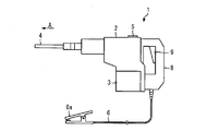
- FIG. 1 is a diagram showing an example of a power tool 1 according to the first embodiment.
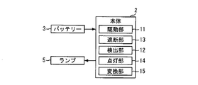
- FIG. 2 is a diagram for explaining the function of the power tool 1.
- the power tool 1 is used for scraping concrete, for example, in an elevator repair work.
- the power tool 1 includes a main body 2, a battery 3, a bit 4, a lamp 5, and a ground wire 6.
- the main body 2 is provided with a handle 8 for the person using the power tool 1 to grasp.
- the main body 2 includes a switch 9 for a person who grips the handle 8 to operate the main body 2.
- FIG. 1 shows an example in which the main body 2 includes a button-type switch 9. Further, the main body 2 includes a drive unit 11, a detection unit 12, a blocking unit 13, and a lighting unit 14.
- the battery 3 is supported by the main body 2.
- the battery 3 may be detachable from the main body 2.
- the electric power required for the power tool 1 is supplied from the battery 3.
- Bit 4 is a metal rod-shaped member for actually shaving concrete.
- the bit 4 is a metal concrete drill bit.
- the bit 4 is supported by the main body 2 so as to extend from the main body 2 in a specific direction.
- the direction in which the bit 4 extends from the main body 2 is also referred to as the A direction.
- the bit 4 is supported by the main body 2 so as to be displaceable along the A direction. Further, the bit 4 may be supported by the main body 2 so as to be rotatable around the A direction.
- the lamp 5 is provided on the main body 2.
- the lamp 5 is arranged at a position visible to the person holding the handle 8.
- the ground wire 6 is an example of means for being connected to a member that is grounded.
- the grounded member is also referred to as a grounded member.
- the ground wire 6 extends from the main body 2.
- the ground wire 6 has a ground terminal 6a at its tip.
- the ground terminal 6a is electrically connected to the bit 4.
- the drive unit 11 drives the bit 4 by being supplied with electric power from the battery 3. For example, when power is supplied from the battery 3, the drive unit 11 vibrates the bit 4 along the A direction. Further, the drive unit 11 rotates the bit 4 around the A direction when power is supplied from the battery 3. When a specific operation is performed on the switch 9, the electric power from the battery 3 is supplied to the drive unit 11. For example, if the main body 2 includes a button-type switch 9, the bit 4 vibrates and rotates when the switch 9 is pressed.
- the detection unit 12 detects that the bit 4 has been grounded. Inside the main body 2, the bit 4 is electrically connected to the battery 3. The ground terminal 6a is electrically connected to the battery 3. When a specific operation is performed on the switch 9, a potential difference is generated between the bit 4 and the ground terminal 6a according to the output voltage of the battery 3. For example, the detection unit 12 detects that the bit 4 is grounded when the resistance value between the bit 4 and the ground terminal 6a is smaller than the reference value.
- FIG. 3 is a diagram schematically showing an example in which the power tool 1 is used in the repair work of the elevator.
- FIG. 4 is a flowchart showing an operation example of the power tool 1 according to the first embodiment.
- the worker moves the power tool 1 onto the car 21 with the power tool 1.
- the ground terminal 6a of the ground wire 6 is connected to the grounded member in the hoistway 22.
- FIG. 3 shows an example in which the sill 23 is welded and fixed to the reinforcing bar 24 via the reinforcing brace 25.
- the threshold 23 and the brace 25 are made of metal.
- the threshold 23 and the brace 25 are examples of grounded members arranged in the hoistway 22.
- the worker may connect the ground terminal 6a to the threshold 23 before performing the chipping work with the power tool 1 on the car 21 in the repair work of the elevator.
- the threshold 23 is provided at each landing.
- the operator may connect the ground terminal 6a to the threshold 23 arranged at the height closest to the work place.
- FIG. 3 shows an example in which the ground wire 6 is connected to the sill 23 by sandwiching the sill 23 with the ground terminal 6a. In the example shown in FIG. 3, the operator can easily attach the ground terminal 6a to the grounded member even from above the car 21.
- the threshold 23 may be replaced. Even if the threshold 23 is removed, the reinforcing bars 24 or braces 25 to which the threshold 23 is fixed are left in the hoistway 22. If the sill 23 has already been removed, the operator may connect the ground terminal 6a to the reinforcing bar 24 or the brace 25 before performing the chipping work with the power tool 1.
- S101 determines Yes. If it is determined to be Yes in S101, power is supplied from the battery 3 to the drive unit 11. As a result, the drive unit 11 drives the bit 4 (S102). In the example shown in this embodiment, in S102, the bit 4 vibrates along the A direction and rotates about the A direction.
- the detection unit 12 determines whether or not the bit 4 is grounded (S103).
- FIG. 3 shows an example in which a metal pipe 26 for protecting an electric wire is buried inside concrete. The metal tube 26 is grounded. Further, as described above, the ground terminal 6a is connected to the grounded member. Therefore, when the bit 4 comes into contact with the metal tube 26 during the chipping operation, the detection unit 12 detects that the bit 4 is grounded (Yes in S103).
- the cutoff unit 13 cuts off the power supply from the battery 3 to the drive unit 11 (S104). Therefore, when the bit 4 comes into contact with the metal tube 26 during the chipping operation, the vibration and rotation of the bit 4 are immediately stopped. This makes it possible to prevent the metal tube 26 from being damaged and the bit 4 from being damaged.
- the lighting unit 14 lights the lamp 5 (S105). By looking at the lit lamp 5, the operator can know that the bit 4 has come into contact with a metal member such as the metal tube 26.
- the lamp 5 is an example of a notification device provided in the main body 2.
- the lighting unit 14 is an example of a notification unit that controls the notification device.
- the lighting unit 14 lighting the lamp 5 is an example of the notification unit operating the alarm.
- the main body 2 may be provided with a buzzer as a notification device. In such a case, the notification unit sounds the buzzer in S105.
- the main body 2 may be provided with both a lamp 5 and a buzzer as an alarm. In such a case, the notification unit turns on the lamp 5 and sounds the buzzer in S105.
- the power tool 1 can detect that the bit 4 comes into contact with a metal member such as a metal tube 26 during the chipping operation. Therefore, the operator does not need to carry the cord reel with the metal sensor onto the car 21 when performing the chipping work on the car 21. The operator does not need to perform the chipping work with the cord reel placed on the car 21, and the work can be performed efficiently.
- the power tool 1 may be adopted by combining a plurality of functions shown below.
- the main body 2 of the power tool 1 may further include a conversion unit 15 as shown in FIG.
- the conversion unit 15 converts the direct current from the battery 3 into alternating current.
- the alternating current from the conversion unit 15 is supplied to the drive unit 11.
- the bit 4 is electrically connected to the conversion unit 15.
- the ground terminal 6a is electrically connected to the conversion unit 15.
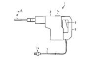
- FIG. 5 is a diagram showing another example of the power tool 1 according to the first embodiment.
- the power tool 1 includes a main body 2, a bit 4, a lamp 5, and a power cord 7.
- the power cord 7 extends from the main body 2.
- the power cord 7 has a plug 7a with a ground terminal.
- the ground terminal of the plug 7a is electrically connected to the bit 4.
- the main body 2 includes a handle 8 and a switch 9. Further, the main body 2 includes a drive unit 11, a detection unit 12, a blocking unit 13, and a lighting unit 14.
- a grounded outlet 27 is often provided on the car 21 for maintenance personnel who maintain the elevator.
- the operator may connect the plug 7a to the outlet 27 before starting the chipping work.
- the electric power required for the power tool 1 is supplied from a commercial power source via a plug 7a connected to the outlet 27.
- the drive unit 11 drives the bit 4 by supplying electric power from a commercial power source to which the plug 7a is connected. For example, when power is supplied from the commercial power source, the drive unit 11 vibrates the bit 4 along the A direction and rotates the bit 4 around the A direction.
- the electric power from the commercial power source is supplied to the drive unit 11 by performing a specific operation on the switch 9.
- the detection unit 12 detects that the bit 4 is grounded, for example, when the resistance value between the ground terminal of the bit 4 and the plug 7a is smaller than the reference value. Therefore, when the bit 4 comes into contact with the metal tube 26 during the chipping operation, the detection unit 12 detects that the bit 4 is grounded.
- the cutoff unit 13 cuts off the power supply from the commercial power supply to which the plug 7a is connected to the drive unit 11. Therefore, when the bit 4 comes into contact with the metal tube 26 during the chipping operation, the vibration and rotation of the bit 4 are immediately stopped. This makes it possible to prevent the metal tube 26 from being damaged and the bit 4 from being damaged.
- the lighting unit 14 lights the lamp 5. At this time, the buzzer provided on the main body 2 may sound. By looking at the lit lamp 5, the operator can know that the bit 4 has come into contact with a metal member such as the metal tube 26.
- the outlet 27 may be removed from the top of the car 21.
- the power tool 1 preferably includes a battery 3 and a ground wire 6.
- the power tool 1 may include both a power cord 7, a battery 3, and a ground wire 6.
- each part indicated by reference numerals 11 to 15 indicates a function possessed by the main body 2 of the power tool 1.
- the function of the main body 2 is realized by, for example, dedicated hardware. Some of the functions of the main body 2 may be realized by software.
- the main body 2 includes a processing circuit including a processor and a memory as hardware resources. The main body 2 realizes the above-mentioned part of the function by executing the program stored in the memory by the processor.
- the present invention can be applied to a power tool in which a bit can unintentionally come into contact with a metal member while the bit is being driven.
Landscapes
- Engineering & Computer Science (AREA)
- Mechanical Engineering (AREA)
- Mining & Mineral Resources (AREA)
- Lift-Guide Devices, And Elevator Ropes And Cables (AREA)
- Drilling And Boring (AREA)
Priority Applications (3)
| Application Number | Priority Date | Filing Date | Title |
|---|---|---|---|
| JP2021569668A JPWO2021140617A1 (https=) | 2020-01-09 | 2020-01-09 | |
| PCT/JP2020/000471 WO2021140617A1 (ja) | 2020-01-09 | 2020-01-09 | 電動工具 |
| CN202080091697.1A CN114901446A (zh) | 2020-01-09 | 2020-01-09 | 电动工具 |
Applications Claiming Priority (1)
| Application Number | Priority Date | Filing Date | Title |
|---|---|---|---|
| PCT/JP2020/000471 WO2021140617A1 (ja) | 2020-01-09 | 2020-01-09 | 電動工具 |
Publications (1)
| Publication Number | Publication Date |
|---|---|
| WO2021140617A1 true WO2021140617A1 (ja) | 2021-07-15 |
Family
ID=76787786
Family Applications (1)
| Application Number | Title | Priority Date | Filing Date |
|---|---|---|---|
| PCT/JP2020/000471 Ceased WO2021140617A1 (ja) | 2020-01-09 | 2020-01-09 | 電動工具 |
Country Status (3)
| Country | Link |
|---|---|
| JP (1) | JPWO2021140617A1 (https=) |
| CN (1) | CN114901446A (https=) |
| WO (1) | WO2021140617A1 (https=) |
Families Citing this family (1)
| Publication number | Priority date | Publication date | Assignee | Title |
|---|---|---|---|---|
| WO2021062392A1 (en) * | 2019-09-26 | 2021-04-01 | Huskie Tools, Inc. | Remotely controlled cutting tool and method |
Citations (5)
| Publication number | Priority date | Publication date | Assignee | Title |
|---|---|---|---|---|
| JPS56126129U (https=) * | 1980-02-25 | 1981-09-25 | ||
| JPS5950616U (ja) * | 1982-09-24 | 1984-04-03 | 明良工業株式会社 | 構造物加工用工具 |
| JPS6281326U (https=) * | 1985-11-11 | 1987-05-25 | ||
| JP2013000863A (ja) * | 2011-06-20 | 2013-01-07 | Hitachi Koki Co Ltd | 電動工具 |
| JP2018058189A (ja) * | 2016-10-07 | 2018-04-12 | 株式会社マキタ | 電動工具 |
Family Cites Families (8)
| Publication number | Priority date | Publication date | Assignee | Title |
|---|---|---|---|---|
| JPS5514211B2 (https=) * | 1973-05-09 | 1980-04-15 | ||
| JPS5030301A (https=) * | 1973-07-19 | 1975-03-26 | ||
| JPS6026944Y2 (ja) * | 1979-07-25 | 1985-08-14 | 日本精密電気株式会社 | コンクリ−ト破砕機器を制御できる埋設金属検出器 |
| DE3207747A1 (de) * | 1982-03-04 | 1983-09-08 | Schützeichel, Johannes, 5466 Neustadt | Einrichtung zur ueberwachung von bohr- und saegearbeiten in bauwerkskoerpern, insbesondere spannbeton-bauwerken |
| DE102005013120A1 (de) * | 2005-03-18 | 2006-09-21 | Fraunhofer-Gesellschaft zur Förderung der angewandten Forschung e.V. | Bohrmaschine mit Metalldetektor |
| DE102009054762A1 (de) * | 2009-12-16 | 2011-06-22 | Hilti Aktiengesellschaft | Steuerungsverfahren für eine handgeführte Werkzeugmaschine und Werkzeugmaschine |
| JP6508412B2 (ja) * | 2016-02-26 | 2019-05-08 | 工機ホールディングス株式会社 | 電動工具 |
| JP3219613U (ja) * | 2018-10-25 | 2019-01-10 | 株式会社畑屋製作所 | コードリール |
-
2020
- 2020-01-09 CN CN202080091697.1A patent/CN114901446A/zh active Pending
- 2020-01-09 JP JP2021569668A patent/JPWO2021140617A1/ja active Pending
- 2020-01-09 WO PCT/JP2020/000471 patent/WO2021140617A1/ja not_active Ceased
Patent Citations (5)
| Publication number | Priority date | Publication date | Assignee | Title |
|---|---|---|---|---|
| JPS56126129U (https=) * | 1980-02-25 | 1981-09-25 | ||
| JPS5950616U (ja) * | 1982-09-24 | 1984-04-03 | 明良工業株式会社 | 構造物加工用工具 |
| JPS6281326U (https=) * | 1985-11-11 | 1987-05-25 | ||
| JP2013000863A (ja) * | 2011-06-20 | 2013-01-07 | Hitachi Koki Co Ltd | 電動工具 |
| JP2018058189A (ja) * | 2016-10-07 | 2018-04-12 | 株式会社マキタ | 電動工具 |
Also Published As
| Publication number | Publication date |
|---|---|
| CN114901446A (zh) | 2022-08-12 |
| JPWO2021140617A1 (https=) | 2021-07-15 |
Similar Documents
| Publication | Publication Date | Title |
|---|---|---|
| CN102012472B (zh) | 建筑机械的漏电检测装置 | |
| CN101939145B (zh) | 机械手控制系统 | |
| JP6814032B2 (ja) | 電動作業機 | |
| EP2217406B1 (en) | A power tool and a method for use of the power tool | |
| EP2554307A1 (en) | Cordless magnetic base drill | |
| CN102012473B (zh) | 建筑机械的漏电检测装置 | |
| JP2009061749A (ja) | 被削材への孔穿け方法及び装置 | |
| CN110869170A (zh) | 电动工具 | |
| JP2008223311A (ja) | カッタビットの摩耗検出装置 | |
| CN112640248B (zh) | 充电控制装置、作业机械及充电控制方法 | |
| WO2021140617A1 (ja) | 電動工具 | |
| JP7265358B2 (ja) | 反力が制御された電気パルス工具 | |
| CN103341858A (zh) | 电缆巡检机器人及其控制系统 | |
| JP2010155302A (ja) | 集塵機 | |
| CN114555289A (zh) | 操作机床的方法和机床 | |
| JP4930430B2 (ja) | 冷凍装置用の電力供給装置 | |
| KR20200008333A (ko) | 활선감지니퍼 | |
| TWI586502B (zh) | 機器人控制系統 | |
| JP5414113B2 (ja) | 鉄筋を含む被切削物を切削する際の鉄筋感知方法及び鉄筋感知装置並びに切削装置 | |
| CN217123059U (zh) | 一种新型垂直钢筋套筒施拧装置 | |
| JP2007045615A (ja) | リフティングマグネットの制御装置及びこれを備えた作業機械 | |
| KR101114693B1 (ko) | 전주 전선 교체장치 및 그 전주 전선 교체장치를 이용한 무정전 배전공법 | |
| JPH0728329Y2 (ja) | 電柱カッター | |
| JPH04135144A (ja) | 切削加工機における工具状態検出装置 | |
| JP4786142B2 (ja) | 建設機械 |
Legal Events
| Date | Code | Title | Description |
|---|---|---|---|
| 121 | Ep: the epo has been informed by wipo that ep was designated in this application |
Ref document number: 20912684 Country of ref document: EP Kind code of ref document: A1 |
|
| ENP | Entry into the national phase |
Ref document number: 2021569668 Country of ref document: JP Kind code of ref document: A |
|
| NENP | Non-entry into the national phase |
Ref country code: DE |
|
| 122 | Ep: pct application non-entry in european phase |
Ref document number: 20912684 Country of ref document: EP Kind code of ref document: A1 |